

Page 1
FormNo.3392-160RevA
Verticutter
Reelmaster
ModelNo.03877—SerialNo.316000001andUp
®
6000-DSeriesCuttingUnit
Registeratwww.T oro.com.
OriginalInstructions(EN)
*3392-160*A
Page 2
WARNING
CALIFORNIA
Proposition65Warning
Thisproductcontainsachemicalorchemicals
knowntotheStateofCaliforniatocausecancer,
birthdefects,orreproductiveharm.
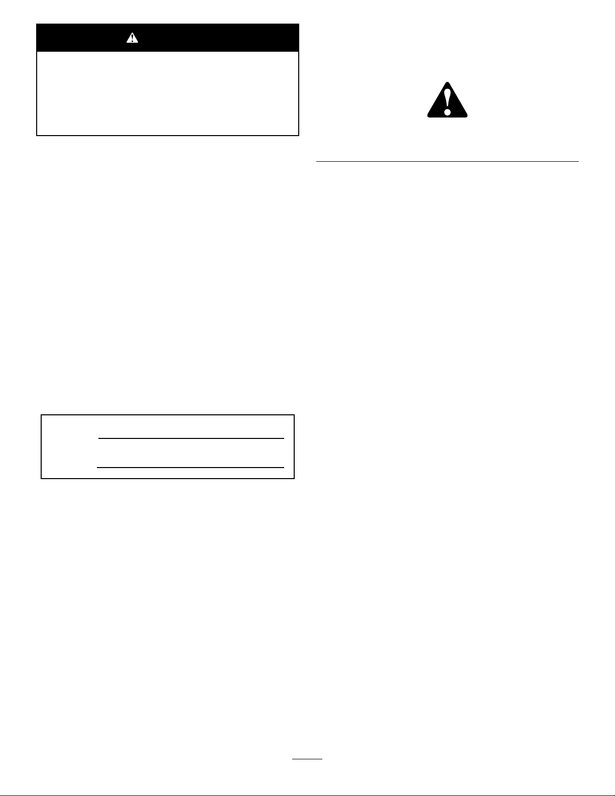
Thismanualidentiespotentialhazardsandhassafety
messagesidentiedbythesafety-alertsymbol(Figure1),
whichsignalsahazardthatmaycauseseriousinjuryordeath
ifyoudonotfollowtherecommendedprecautions.
Figure1
ThisproductcomplieswithallrelevantEuropeandirectives.
Fordetails,pleaseseetheDeclarationofIncorporation(DOI)
atthebackofthispublication.
Introduction
Readthisinformationcarefullytolearnhowtooperateand
maintainyourproductproperlyandtoavoidinjuryand
productdamage.Youareresponsibleforoperatingthe
productproperlyandsafely.
YoumaycontactTorodirectlyatwww .Toro.comforproduct
safetyandoperationtrainingmaterials,accessoryinformation,
helpndingadealer,ortoregisteryourproduct.
Wheneveryouneedservice,genuineT oroparts,oradditional
information,contactanAuthorizedServiceDealerorToro
CustomerServiceandhavethemodelandserialnumbersof
yourproductready .Writethenumbersinthespaceprovided.
ModelNo.
SerialNo.
1.Safety-alertsymbol
Thismanualuses2wordstohighlightinformation.
Importantcallsattentiontospecialmechanicalinformation
andNoteemphasizesgeneralinformationworthyofspecial
attention.
Contents
Safety...........................................................................3
SafetyandInstructionalDecals.................................3
Setup............................................................................4
1InspectingtheVerticutter.......................................5
2InstallingtheTransportRollers...............................5
3AdjustingtheBladeDepth.....................................5
4AdjustingtheRearGrassShield..............................6
5AdjustingtheRollerScrapers..................................6
6AdjustingtheTransportRollers...............................7
7MountingtheLiftBracketsandChains.....................7
8InstallingtheCounterweights.................................8
9InstallingtheVerticutterReels................................9
Operation....................................................................10
TrainingPeriod......................................................10
OperatingTips......................................................10
Maintenance.................................................................11
LubricatingtheV erticutter.......................................11
AdjustingtheReelBearings......................................11
ReplacingtheBlades...............................................12
©2016—TheToro®Company
8111LyndaleAvenueSouth
Bloomington,MN55420
Contactusatwww.Toro.com.
2
PrintedintheUSA
AllRightsReserved
Page 3
Safety
isadvisableandrequiredbysomelocalordinancesand
insuranceregulations.
ThismachinehasbeendesignedinaccordancewithENISO
5395:2013.
Improperuseormaintenanceofthisequipmentcan
resultininjuryordeath.T oreducethepotentialfor
injuryordeath,complywiththefollowingsafety
instructions.
•Read,understand,andfollowallinstructionsinthe
tractionunitOperator’ sManualbeforeoperatingthe
verticutters.
•Read,understand,andfollowallinstructionsinthis
Operator’sManualbeforeoperatingtheverticutters.
•Neverallowchildrentooperatethetractionunitorthe
verticutters.Donotallowadultstooperatethetraction
unitortheverticutterswithoutproperinstruction.Only
trainedoperatorswhohavereadthisOperator’sManual
shouldoperatetheverticutters.
•Neveroperatetheverticutterswhentired,ill,orunderthe
inuenceofdrugsoralcohol.
•Keepallshieldsandsafetydevicesinplace.Ifashield,a
safetydevice,oradecalisillegibleordamaged,repairor
replaceitbeforeresumingoperation.Also,tightenany
loosenuts,bolts,andscrewstoensurethattheverticutters
areinsafeoperatingcondition.
•Alwayswearsubstantial,slip-resistantfootwear.Always
wearlongpants.Wearingsafetyglassesandsafetyshoes
•Tiebacklonghair.Donotwearjewelry.
•Removealldebrisorotherobjectsthatmightbepicked
upandthrownbythereelbladesofthecuttingunit.Keep
allbystandersawayfromtheworkingarea.
•Iftheverticutterbladesstrikeasolidobjectortheunit
vibratesabnormally,stopandshuttheengineoff.Check
theverticutterfordamagedparts.Repairanydamage
beforestartingandoperatingtheverticutter.
•Lowertheverticutterstotheground,settheparking
brake,shutofftheengine,andremovethekeyfrom
theignitionswitchwheneveryouleavethemachine
unattended.
•Besurethattheverticuttersareinsafeoperating
conditionbykeepingnuts,bolts,andscrewstight.
•Removethekeyfromtheswitchtopreventaccidental
startingoftheenginewhenservicing,adjusting,orstoring
themachine.
•Performonlythosemaintenanceinstructionsdescribedin
thismanual.Ifmajorrepairsareeverneededorassistance
isdesired,contactanAuthorizedT oroDistributor.
•Toensureoptimumperformanceandcontinuedsafety
certicationofthemachine,useonlygenuineToro
replacementpartsandaccessories.Replacementparts
andaccessoriesmadebyothermanufacturerscouldbe
dangerous,andsuchusecouldvoidtheproductwarranty.
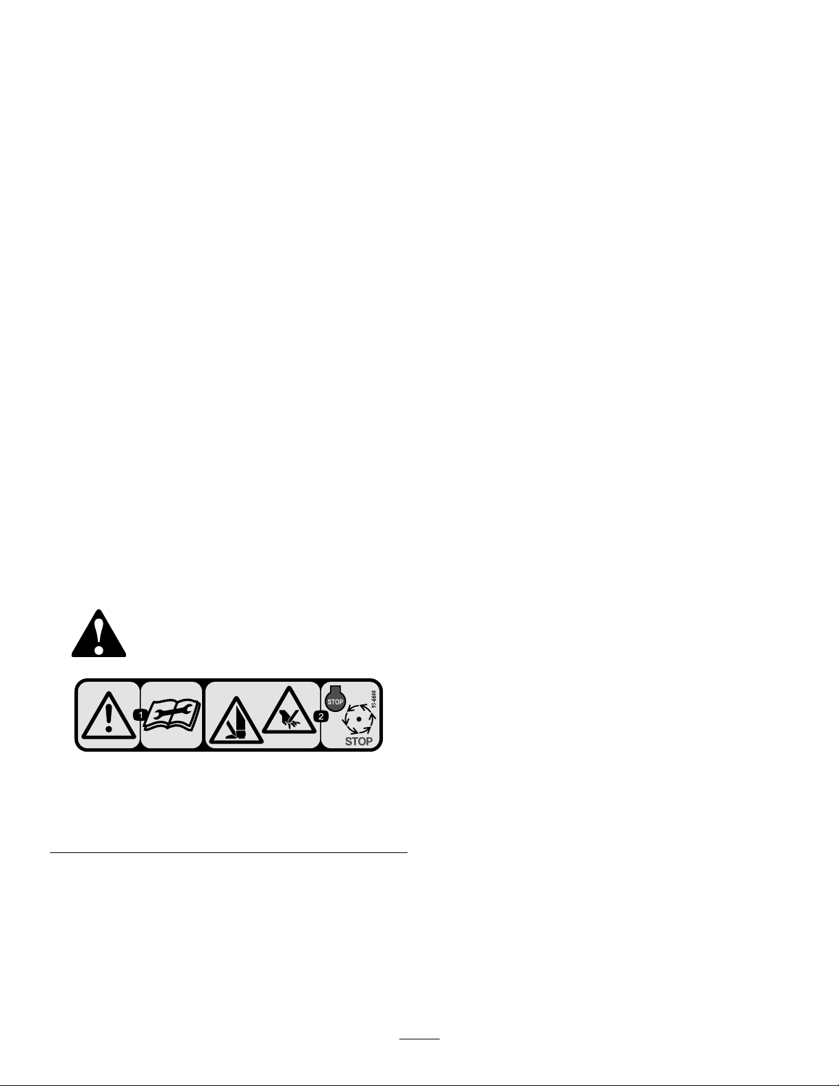
SafetyandInstructionalDecals
Safetydecalsandinstructionsareeasilyvisibletotheoperatorandarelocatednearanyareaofpotential
danger.Replaceanydecalthatisdamagedorlost.
93-6688
1.Warning—readthe
Operator’sManualbefore
performingmaintenance.
2.Cuttinghazardofhandor
foot—shutofftheengine
andwaitforallmoving
partstostop.
3
Page 4

Setup
LooseParts
Usethechartbelowtoverifythatallpartshavebeenshipped.
ProcedureDescription
1
2
3
4
5
6
7
8
9
Qty.
Nopartsrequired
Transportroller2Installthetransportrollers.
Nopartsrequired
Nopartsrequired
Nopartsrequired
Nopartsrequired
Liftchain
Chainbracket
U-bolt1
Nut3
Washer1
Screw
Nopartsrequired
Screw
O-ring
–
–
–
–
–
1
1
1
–
1
1
Inspecttheverticutter.
Adjustthebladedepth.
Adjustthereargrassshield.
Adjusttherollerscrapers.
Adjustthetransportrollers.
Mounttheliftbracketsandchains.
Installthecounterweights.
Installtheverticutterreels.
Use
MediaandAdditionalParts
Description
Operator’sManual
PartsCatalog
Important:Withouttheseparts,totalsetupcannotbecompleted.
Note:Determinetheleftandrightsidesofthemachinefromthenormaloperatingposition.
Qty.
1
1
Reviewthematerialandsaveitinanappropriateplace.
Use
4
Page 5
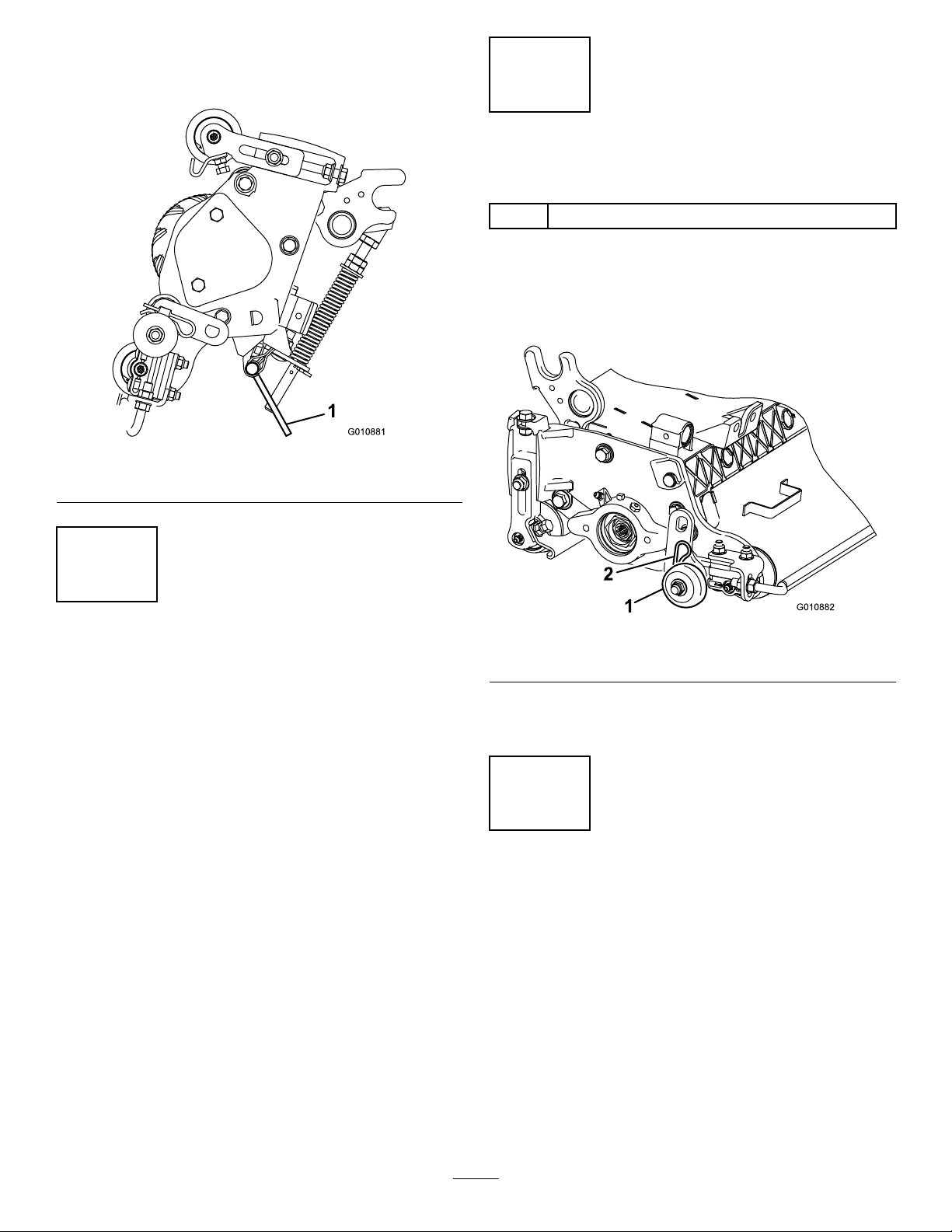
Note:Whenevertheverticutterhastobetippedtoexpose
theverticutterblades,usethekickstand(suppliedwith
tractionunit);refertoFigure2.
Figure2
1.Kickstand
2
InstallingtheTransportRollers
Partsneededforthisprocedure:
2Transportroller
Procedure
Secureatransport-rollerbrackettoeachside-platepinwith
acotterpin(Figure3).
1
InspectingtheVerticutter
NoPartsRequired
Procedure
1.Checkeachendofthereelforgrease.
Note:Greaseshouldbevisibleinthereelbearings
andtheinternalsplinesofthereelshaft.
2.Ensurethatallnutsandboltsaresecurelytightened.
3.Ensurethatthecarrier-framesuspensionoperates
freelyanddoesnotbindwhenmovedbackandforth.
Figure3
1.Transportroller
Note:Therollershouldbepositionedtotherearofthe
verticutter.
2.Cotterpin
3
AdjustingtheBladeDepth
NoPartsRequired
Procedure
Note:Themaximumrecommendedbladepenetrationdepth
is6mm(1/4inch).
1.Placetheverticutterreelonalevelsurface.
2.Place2gaugebars,whichhavethedesireddepthof
bladepenetrationbelowtheground,underthefront
andrearrollersoftheverticutterreel(oneachendof
thereel);refertoFigure4.
5
Page 6

1.Gaugebar(1/4inch)
Figure4
2.Adjustingbolt
Figure5
1.Reargrassshield2.Pivotcapscrew
2.Rotatethegrassshieldtothedesiredsetting,and
tightenthecapscrews(Figure5).
Note:Theverticutterbladesmustnottouchthe
gaugebars.
3.Turntheadjustingboltoneachheight-of-cutbracket
(Figure4)sothatthereelbladescomeincontactwith
thelevelsurfaceonbothends.
Note:Astheverticutterbladeswear,thediameterof
thereelwilldecreaseandthedepthsettingwillchange.
Checkthedepthsettingperiodicallytoensurethatthe
desiredsettingisachieved.
4
AdjustingtheRearGrass Shield
NoPartsRequired
Procedure
WARNING
Openingtherearshieldtoomuchcouldcause
personalinjuryduetothrowndebris.
Donotopentherearshieldsothatitishigherthan
leveltotheground.
5
AdjustingtheRollerScrapers
NoPartsRequired
Procedure
1.Loosentheangenutsthatsecuretherollerscrapers
(Figure6).
Note:Whenoperatinginturfconditionswheremuchdebris
orunusuallyheavythatchisencountered,opentherear
dischargeshieldtohelpallowthedebristodischargefrom
thereel.
1.Loosenthecapscrewsonthepivotofthegrassshield
(Figure5).
Figure6
1.Frontrollerscraper3.Transportroller
2.Rearrollerscraper
6
4.Cotterpin
Page 7

2.Movethescraperrodsinorouttoattain0.0to0.75
mm(0.0to0.03inch)clearancebetweenthescraper
andtheroller.
3.Ensurethatthescraperrodisparalleltotherollerand
tothelevelsurface.
4.Tightentheangenutstolocktheadjustment.
6
AdjustingtheTransport Rollers
NoPartsRequired
7
MountingtheLiftBracketsand Chains
Partsneededforthisprocedure:
1
Liftchain
1
Chainbracket
1U-bolt
3Nut
1Washer
1
Screw
Procedure
Beforeyoulowertheverticutterstotheshopoororremove
themfromthetractionunit,lowerthetransportrollers
(Figure6)toprotectthebladesfromhardsurfacecontact.
1.Removethecotterpinthatsecuresthetransportroller
brackettotheside-platepin.
2.Positionthetransportrollerasfollows:
•Lowertherollerbracketbeforetheverticutteris
loweredtotheshopoor.
•Raisetherollerbracketaftertheverticutterisraised
totheoperatingposition.
3.Securethetransportrollerbrackettotheside-platepin
withthecotterpin.
4.Repeattheprocedureontheoppositeendofthe
verticutter.
Procedure
MountachainbrackettoeachliftarmwithaU-boltand2
nuts.Positionthebracketsasfollows:
1.Onliftarms1,4,and5,positionthechainbracketsand
U-bolts38cm(15inches)behindthecenterlineofthe
pivotknuckle(Figure7).
Figure7
1.38cm(15inches)3.Liftarms1and5
2.Liftarm4
Note:Onliftarms1and5,thebracketsshouldbe
rotatedtotheright10°fromvertical(Figure7).
Note:Onliftarm4,thebracketshouldberotatedto
theleft10°fromvertical(Figure7).
7
Page 8

2.Onliftarms2and3,positionthebracketsandU-bolts
38cm(15inches)behindthecenterlineofthepivot
knuckle(Figure8).
Note:Rotatethebrackets10°totheoutboardside
ofthemachine.
4.TightenalltheU-boltnutsto52to65N∙m(38to48
ft-lb).
5.Mountaliftchaintoeachchainbracketwithascrew ,a
washer,andanut,positioningthemasshowninFigure
10.
Figure10
1.Liftchain2.Chainbracket
Figure8
1.38cm(15inches)2.Liftarm3
3.Onliftarms6and7,positionthebracketsandU-bolts
36.8cm(14-1/2inches)behindthecenterlineofthe
pivotknuckle(
8
InstallingtheCounterweights
NoPartsRequired
Procedure
Important:Whenloweringtheverticutterreels,take
caretopreventdamagetothereelbladesduetocontact
withaconcreteoororapavedsurface.Lowerthe
transportrollersbeforeloweringtheverticutterstoa
concreteoororapavedsurface.
Youcaninstalltheverticuttersatanyofthe7locationson
thetractionunit.Figure11showstheorientationofthe
hydraulicdrivemotorforeachofthelocations.Foranyof
thelocationsrequiringthemotortobemountedontheright
endoftheverticutters,installacounterweightontheleftend
oftheverticutters.Forthelocationsrequiringthemotorto
bemountedontheleftend,installacounterweightonthe
rightendoftheverticutters.
Figure9
1.36.8cm(14-1/2inches)2.Liftarm7
8
Page 9

Figure11
1.Cuttingunit16.Cuttingunit6
2.Cuttingunit27.Cuttingunit7
3.Cuttingunit3
4.Cuttingunit4
5.Cuttingunit5
Note:Thecounterweightsareshippedinstalledtotheleft
endoftheverticutters.The2capscrews,shippedintheloose
partsbag,aretobeusedforsecuringthehydraulicmotor.
8.Reelmotor
9.Weight
9
3.Securepivotknuckletocarrierframewithathrust
washer,aatwasher,andaange-headcapscrew
(Figure12).
4.Insertathrustwasherontotheverticalshaftofthe
pivotknuckle(Figure12).
5.Ifremoved,inserttheverticalshaftofthepivotknuckle
intothelift-armpivothub(Figure12).
Note:Guidethepivotknuckleinplacebetweenthe
2rubbercenteringbumpersintheundersideofthe
lift-armsteeringplate.
6.Insertthelynchpinintothecrossholeonthe
pivot-knuckleshaft(Figure12).
7.Securethelift-armchaintothecuttingunitchain
bracket(Figure13)withthesnapperpinasfollows:
InstallingtheVerticutterReels
Partsneededforthisprocedure:
1
Screw
1
O-ring
Procedure
1.Insertathrustwasherontohorizontalshaftofpivot
knuckleasshowninFigure12.
Figure13
•Oncuttingunits1,4,5,6,and7,useonly6ofthe
chainlinks.
•Oncuttingunits2and3,useall7ofthechainlinks.
8.Coatthesplinesofthereelmotorwithcleangrease.
9.OilthereelmotorO-ringandinstallitontothemotor
ange.
10.Installthemotorbyrotatingitclockwisesothatthe
motorangesclearthecapscrews(Figure14).
Figure12
1.Carrierframe
2.Pivotknuckle
3.Lift-armsteeringplate
2.Insertthehorizontalshaftofthepivotknuckleintothe
mountingtubeofthecarrierframe(Figure12).
4.Lynchpin
5.Steeringlockingpin
9
Page 10

Operation
TrainingPeriod
Beforeoperatingtheverticutterreels,evaluatethe
performanceofthereelatthedesiredsetting.Operatethem
inaclear,unusedareatodetermineiftheywillachievethe
desiredresults.Adjustthemasdesired.
OperatingTips
•Operatethetractionunitatfullthrottle,fullreelspeed
(setting11)andbetween5to8km/h(3to5mph).
•Themaximumrecommendedbladepenetrationdepth
is6mm(1/4inch).
Figure14
1.Reeldrivemotor
Note:Rotatethemotorcounterclockwiseuntilthe
angesencirclethecapscrews;then,tightenthecap
screws.
Important:Ensurethatthereelmotorhosesare
nottwisted,kinkedorintheriskofbeingpinched.
Note:Ifaxedcuttingunitpositionisrequired,
insertthesteeringlockingpinintothepivotknuckle
mountinghole.
11.Hookthespringwirearoundthebottomofthesteering
lockingpin(Figure12).
2.Capscrew
•Powerrequirementstooperatetheverticutterreelswill
varywithturfandsoilconditions.Travelspeedmayneed
tobereducedinsomeconditions.
•Whenoperatinginturfconditionswithmuchdebrisor
unusuallyheavythatch,openthereardischargeshieldto
helpallowthedebristodischargefromthereel.
WARNING
Openingtherearshieldtoomuchcouldcause
personalinjuryduetothrowndebris.
Donotopentherearshieldsothatitishigherthan
leveltotheground.
10
Page 11

Maintenance
LubricatingtheVerticutter
Eachcuttingunithas7greasettingsthatyoumustlubricate
weeklywithNo.2lithiumgrease.Thelubricationpointsare
thefrontroller(2),therearroller(2),thereelbearings(2),and
thebed-knifeadjuster.
Important:Lubricatingthecuttingunitsimmediately
afterwashinghelpspurgewateroutofthebearingsand
increasesbearinglife.
1.Wipeeachgreasettingwithacleanrag.
2.Applygreaseuntilcleangreasecomesoutoftheroller
sealsandthebearingreliefvalve(Figure15).
AdjustingtheReelBearings
Toensurelonglifeofthereelbearings,periodicallycheckfor
anyreelendplay.Checkandadjustthebearingsasfollows:
1.Holdontothereelshaftandtrytomovethereel
assemblysidetoside(Figure16).
Figure16
1.Reelshaft
Figure15
1.Reliefvalve
3.Wipeanyexcessgreaseaway .
2.Ifthereisanyendplay,proceededasfollows:
A.Loosentheexternalsetscrewthatsecuresthe
bearingadjustingnuttothebearinghousing
locatedontheleftsideofthecuttingunit(Figure
17).
B.Usea1-3/8inchsocketwrenchtoslowlytighten
thebearingadjustmentnutuntilthereisnoend
playinthereel.Ifadjustingthenutdoesnot
eliminatereelendplay,replacethereelbearings.
Important:Thereelbearingsdonotrequire
preload.Overtighteningthebearingadjuster
nutwilldamagethereelbearings.
Figure17
1.Setscrew
3.Tightenthesetscrewthatsecuresthebearingadjusting
nuttothebearinghousing.Torquethesetscrewto136
to169N∙cm(12to15in-lb).
11
2.Bearingadjustingnut
Page 12

ReplacingtheBlades
5.Continuetoinstallspacersandbladesinthismanner
untilthefullcomplementofbladeshavebeeninstalled.
RemovingtheBladesfromtheShaft
1.Securetheendoftheverticuttershaftthathasonly1
washerand1nutinavise.
2.Onotherendoftheshaft,rotatethenut
counterclockwiseandremovethenut.
WARNING
Thebladesareextremelysharpandmayhave
burrsthatwillcutyourhands.
Usecautionwhenremovingthebladesfrom
theshaft.
3.Removethesmallspacer,thewasher,theblades,and
thelargespacers.
Important:Donotinverttheverticutterreelblades
whendisassemblingorreversetheorderwhen
assemblingthem.Notetheverticutterbladesindex
hole.Theindexholeisprovidedforassemblyinorderto
obtaintheproperhelixfortheverticutterreel.
InstallingtheBlades
Note:Whenproperlyassembled,thebladesare
staggeredinsuchamannerastoappearlikeahelix.
6.Installthesmallspacertotheshaft.
7.ApplyblueLoctite242tothenut.
8.Installthenutontotheshaft,(machinedsideofthenut
towardthespacer)andtightenitto108to136N∙m
(80to100ft-lb).
1.Cleanandlubricatethesquareshaftwithalightcoating
ofgrease.
2.Installablade.
3.Installaspacer.
Important:Donotinvertthebladeswhen
installingthemontheshaft.Ifthebladesare
inverted,thebladesthatareinuse(rounded)will
bemixedwiththesharpendsofthebladesthat
werenotinuse.Thiswillcauseunsatisfactory
performanceintheverticutterreelunit.Pay
closeattentionwhenremovingandinstallingthe
verticutterblades.
4.Installthenextbladeclockwisesothattheindex
referencehole(Figure18)isnotalignedwiththerst
bladeholeby1atoftheshaft.
1.Indexreferencehole
Figure18
12
Page 13

Notes:
13
Page 14

DeclarationofIncorporation
TheT oroCompany,811 1LyndaleAve.South,Bloomington,MN,USAdeclaresthatthefollowingunit(s)
conform(s)tothedirectiveslisted,wheninstalledinaccordancewiththeaccompanyinginstructionsontocertain
ToromodelsasindicatedontherelevantDeclarationsofConformity.
ModelNo.
03877316000001andUpVerticutter
SerialNo.
ProductDescriptionInvoiceDescription
7"VERTICUTTER-RM6000
GeneralDescription
Verticutter
Directive
2006/42/EC
RelevanttechnicaldocumentationhasbeencompiledasrequiredperPartBofAnnexVIIof2006/42/EC.
Wewillundertaketotransmit,inresponsetorequestsbynationalauthorities,relevantinformationonthispartly
completedmachinery.Themethodoftransmissionshallbeelectronictransmittal.
ThismachineryshallnotbeputintoserviceuntilincorporatedintoapprovedToromodelsasindicatedonthe
associatedDeclarationofConformityandinaccordancewithallinstructions,wherebyitcanbedeclaredin
conformitywithallrelevantDirectives.
Certied:EUTechnicalContact:
MarcelDutrieux
ManagerEuropeanProductIntegrity
ToroEuropeNV
Nijverheidsstraat5
2260Oevel
DavidKlisBelgium
Sr.EngineeringManager
811 1LyndaleAve.South
Bloomington,MN55420,USA
January12,2016
Tel.+3216386659
14
Page 15

InternationalDistributorList
Distributor:
AgrolancKft
AsianAmericanIndustrial(AAI)
B-RayCorporation
BrisaGoodsLLC
CascoSalesCompany
CeresS.A.CostaRica
CSSCTurfEquipment(pvt)Ltd.SriLanka
CyrilJohnston&Co.
CyrilJohnston&Co.RepublicofIreland
FatDragon
FemcoS.A.Guatemala
FIVEMANSNew-T echCo.,LtdChina
ForGarderOU
G.Y .K.CompanyLtd.
GeomechanikiofAthensGreece
GolfinternationalTurizm
HakoGroundandGardenSweden
HakoGroundandGarden
HayterLimited(U.K.)
HydroturfInt.CoDubai
HydroturfEgyptLLC
IrrimacPortugal351212388260T oroEuropeNVBelgium3214562960
IrrigationProductsInt'lPvtLtd.India00914424494387ValtechMorocco212537663636
JeanHeybroekb.v.Netherlands31306394611VictusEmakPoland48618238369
Country:
Hungary3627539640
HongKong85224977804
Korea82325512076
Mexico12104952417
PuertoRico7877888383
NorthernIreland442890813121
China
Estonia3723846060
Japan81726325861Riversa
Turkey902163365993
Norway4722907760
UnitedKingdom441279723444
UnitedArabEmirates97143479479T-MarktLogisticsLtd.Hungary3626525500
Egypt2025194308ToroAustraliaAustralia61395807355
PhoneNumber:Distributor:
MaquiverS.A.Colombia
MaruyamaMfg.Co.Inc.
Mountelda.s.CzechRepublic
Mountelda.s.Slovakia
5062391138
94112746100
442890813121ParklandProductsLtd.NewZealand6433493760
8861080841322
5024423277
86-10-63816136
30109350054
4635100000
MunditolS.A.
NormaGarden
OslingerTurfEquipmentSA
OyHakoGroundandGardenAb
Perfetto
PratoverdeSRL.
Prochaska&Cie
RTCohen2004Ltd.
LelyTurfcare
Lely(U.K.)Limited
SolvertS.A.S.
SpyprosStavrinidesLimitedCyprus
SurgeSystemsIndiaLimited
Country:
Japan81332522285
Argentina541 148219999
Russia749541 16120
Ecuador59342396970
Finland35898700733
Poland48618208416
Italy390499128128
Austria4312785100
Israel97298617979
Spain
Denmark4566109200
UnitedKingdom441480226800
France33130817700
India911292299901
PhoneNumber:
5712364079
420255704220
420255704220
34952837500
35722434131
EuropeanPrivacyNotice
TheInformationToroCollects
ToroWarrantyCompany(Toro)respectsyourprivacy.Inordertoprocessyourwarrantyclaimandcontactyouintheeventofaproductrecall,weaskyou
tosharecertainpersonalinformationwithus,eitherdirectlyorthroughyourlocalT orocompanyordealer.
TheT orowarrantysystemishostedonserverslocatedwithintheUnitedStateswhereprivacylawmaynotprovidethesameprotectionasapplies
inyourcountry.
BYSHARINGYOURPERSONALINFORMATIONWITHUS,YOUARECONSENTINGTOTHEPROCESSINGOFYOURPERSONALINFORMATION
ASDESCRIBEDINTHISPRIV ACYNOTICE.
TheWayT oroUsesInformation
Toromayuseyourpersonalinformationtoprocesswarrantyclaims,tocontactyouintheeventofaproductrecallandforanyotherpurposewhichwetell
youabout.ToromayshareyourinformationwithT oro'safliates,dealersorotherbusinesspartnersinconnectionwithanyoftheseactivities.Wewillnot
sellyourpersonalinformationtoanyothercompany.Wereservetherighttodisclosepersonalinformationinordertocomplywithapplicablelawsand
withrequestsbytheappropriateauthorities,tooperateoursystemsproperlyorforourownprotectionorthatofotherusers.
RetentionofyourPersonalInformation
Wewillkeepyourpersonalinformationaslongasweneeditforthepurposesforwhichitwasoriginallycollectedorforotherlegitimatepurposes
(suchasregulatorycompliance),orasrequiredbyapplicablelaw .
Toro'sCommitmenttoSecurityofYourPersonalInformation
Wetakereasonableprecautionsinordertoprotectthesecurityofyourpersonalinformation.Wealsotakestepstomaintaintheaccuracyandcurrent
statusofpersonalinformation.
AccessandCorrectionofyourPersonalInformation
Ifyouwouldliketorevieworcorrectyourpersonalinformation,pleasecontactusbyemailatlegal@toro.com.
AustralianConsumerLaw
AustraliancustomerswillnddetailsrelatingtotheAustralianConsumerLaweitherinsidetheboxoratyourlocalToroDealer.
374-0269RevK
Page 16

TheT oroWarranty
ATwo-YearLimitedWarranty
ConditionsandProductsCovered
TheToroCompanyanditsafliate,T oroWarrantyCompany,pursuant
toanagreementbetweenthem,jointlywarrantyourT oroCommercial
product(“Product”)tobefreefromdefectsinmaterialsorworkmanship
fortwoyearsor1500operationalhours*,whicheveroccursrst.This
warrantyisapplicabletoallproductswiththeexceptionofAerators
(refertoseparatewarrantystatementsfortheseproducts).Wherea
warrantableconditionexists,wewillrepairtheProductatnocosttoyou
includingdiagnostics,labor,parts,andtransportation.Thiswarranty
beginsonthedatetheProductisdeliveredtotheoriginalretailpurchaser .
*Productequippedwithanhourmeter.
InstructionsforObtainingWarrantyService
YouareresponsiblefornotifyingtheCommercialProductsDistributoror
AuthorizedCommercialProductsDealerfromwhomyoupurchasedthe
Productassoonasyoubelieveawarrantableconditionexists.Ifyouneed
helplocatingaCommercialProductsDistributororAuthorizedDealer,or
ifyouhavequestionsregardingyourwarrantyrightsorresponsibilities,
youmaycontactusat:
ToroCommercialProductsServiceDepartment
ToroWarrantyCompany
811 1LyndaleAvenueSouth
Bloomington,MN55420-1196
952–888–8801or800–952–2740
E-mail:commercial.warranty@toro.com
OwnerResponsibilities
AstheProductowner,youareresponsibleforrequiredmaintenanceand
adjustmentsstatedinyourOperator'sManual.Failuretoperformrequired
maintenanceandadjustmentscanbegroundsfordisallowingawarranty
claim.
ItemsandConditionsNotCovered
Notallproductfailuresormalfunctionsthatoccurduringthewarranty
periodaredefectsinmaterialsorworkmanship.Thiswarrantydoesnot
coverthefollowing:
•Productfailureswhichresultfromtheuseofnon-T ororeplacement
parts,orfrominstallationanduseofadd-on,ormodiednon-Toro
brandedaccessoriesandproducts.Aseparatewarrantymaybe
providedbythemanufactureroftheseitems.
•Productfailureswhichresultfromfailuretoperformrecommended
maintenanceand/oradjustments.Failuretoproperlymaintainyour
ToroproductpertheRecommendedMaintenancelistedinthe
Operator’sManualcanresultinclaimsforwarrantybeingdenied.
•ProductfailureswhichresultfromoperatingtheProductinanabusive,
negligent,orrecklessmanner.
•Partssubjecttoconsumptionthroughuseunlessfoundtobedefective.
Examplesofpartswhichareconsumed,orusedup,duringnormal
Productoperationinclude,butarenotlimitedto,brakepadsand
linings,clutchlinings,blades,reels,rollersandbearings(sealedor
greasable),bedknives,sparkplugs,castorwheelsandbearings,tires,
lters,belts,andcertainsprayercomponentssuchasdiaphragms,
nozzles,andcheckvalves,etc.
•Failurescausedbyoutsideinuence.Conditionsconsideredtobe
outsideinuenceinclude,butarenotlimitedto,weather,storage
practices,contamination,useofunapprovedfuels,coolants,lubricants,
additives,fertilizers,water,orchemicals,etc.
•Failureorperformanceissuesduetotheuseoffuels(e.g.gasoline,
diesel,orbiodiesel)thatdonotconformtotheirrespectiveindustry
standards.
•Normalnoise,vibration,wearandtear ,anddeterioration.
•Normal“wearandtear”includes,butisnotlimitedto,damagetoseats
duetowearorabrasion,wornpaintedsurfaces,scratcheddecalsor
windows,etc.
Parts
Partsscheduledforreplacementasrequiredmaintenancearewarranted
fortheperiodoftimeuptothescheduledreplacementtimeforthatpart.
Partsreplacedunderthiswarrantyarecoveredforthedurationofthe
originalproductwarrantyandbecomethepropertyofT oro.T orowillmake
thenaldecisionwhethertorepairanyexistingpartorassemblyorreplace
it.T oromayuseremanufacturedpartsforwarrantyrepairs.
DeepCycleandLithium-IonBatteryWarranty:
DeepcycleandLithium-Ionbatterieshaveaspeciedtotalnumberof
kilowatt-hourstheycandeliverduringtheirlifetime.Operating,recharging,
andmaintenancetechniquescanextendorreducetotalbatterylife.Asthe
batteriesinthisproductareconsumed,theamountofusefulworkbetween
chargingintervalswillslowlydecreaseuntilthebatteryiscompletelyworn
out.Replacementofwornoutbatteries,duetonormalconsumption,
istheresponsibilityoftheproductowner.Batteryreplacementmaybe
requiredduringthenormalproductwarrantyperiodatowner’sexpense.
Note:(Lithium-Ionbatteryonly):ALithium-Ionbatteryhasapartonly
proratedwarrantybeginningyear3throughyear5basedonthetime
inserviceandkilowatthoursused.RefertotheOperator'sManualfor
additionalinformation.
MaintenanceisatOwner’sExpense
Enginetune-up,lubrication,cleaningandpolishing,replacementoflters,
coolant,andcompletingrecommendedmaintenancearesomeofthe
normalservicesT oroproductsrequirethatareattheowner’sexpense.
GeneralConditions
RepairbyanAuthorizedToroDistributororDealerisyoursoleremedy
underthiswarranty.
NeitherTheToroCompanynorToroWarrantyCompanyisliablefor
indirect,incidentalorconsequentialdamagesinconnectionwiththe
useoftheToroProductscoveredbythiswarranty,includingany
costorexpenseofprovidingsubstituteequipmentorserviceduring
reasonableperiodsofmalfunctionornon-usependingcompletion
ofrepairsunderthiswarranty.ExceptfortheEmissionswarranty
referencedbelow,ifapplicable,thereisnootherexpresswarranty.All
impliedwarrantiesofmerchantabilityandtnessforusearelimitedto
thedurationofthisexpresswarranty.
Somestatesdonotallowexclusionsofincidentalorconsequential
damages,orlimitationsonhowlonganimpliedwarrantylasts,sotheabove
exclusionsandlimitationsmaynotapplytoyou.Thiswarrantygivesyou
speciclegalrights,andyoumayalsohaveotherrightswhichvaryfrom
statetostate.
Noteregardingenginewarranty:
TheEmissionsControlSystemonyourProductmaybecoveredby
aseparatewarrantymeetingrequirementsestablishedbytheU.S.
EnvironmentalProtectionAgency(EP A)and/ortheCaliforniaAirResources
Board(CARB).Thehourlimitationssetforthabovedonotapplytothe
EmissionsControlSystemWarranty.RefertotheEngineEmissionControl
WarrantyStatementsuppliedwithyourproductorcontainedintheengine
manufacturer’sdocumentationfordetails
CountriesOtherthantheUnitedStatesorCanada
CustomerswhohavepurchasedT oroproductsexportedfromtheUnitedStatesorCanadashouldcontacttheirT oroDistributor(Dealer)toobtain
guaranteepoliciesforyourcountry ,province,orstate.IfforanyreasonyouaredissatisedwithyourDistributor'sserviceorhavedifcultyobtaining
guaranteeinformation,contacttheT oroimporter.
374-0253RevD
 Loading...