

Page 1
FormNo.3359-861RevA
8and11BladeDPACuttingUnits
with7inchReels
Reelmaster
ModelNo.03863—SerialNo.280000001andUp
ModelNo.03864—SerialNo.280000001andUp
®
6500&6700TractionUnits
Registeratwww.T oro.com.OriginalInstructions(EN)
Page 2
Introduction
Readthisinformationcarefullytolearnhowtooperate
andmaintainyourproductproperlyandtoavoidinjury
andproductdamage.Youareresponsibleforoperating
theproductproperlyandsafely .
YoumaycontactTorodirectlyatwww .Toro.comfor
productandaccessoryinformation,helpndinga
dealer,ortoregisteryourproduct.
Wheneveryouneedservice,genuineT oroparts,or
additionalinformation,contactanAuthorizedService
DealerorToroCustomerServiceandhavethemodel
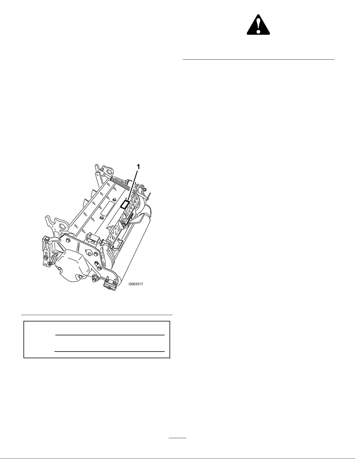
andserialnumbersofyourproductready .Figure1
identiesthelocationofthemodelandserialnumbers
ontheproduct.Writethenumbersinthespace
provided.
Figure1
1.Locationofthemodelandserialnumbers
Figure2
1.Safetyalertsymbol
Thismanualuses2otherwordstohighlightinformation.
Importantcallsattentiontospecialmechanical
informationandNoteemphasizesgeneralinformation
worthyofspecialattention.
Contents
Introduction.................................................................2
Safety...........................................................................3
SafetyandInstructionalDecals.............................3
Setup............................................................................4
1Inspection.........................................................5
2RemovingtheTipperAssemblies.......................5
3MounttheLiftBracketsandChains....................5
4CuttingUnitKickstand......................................6
5AdjustingtheRearShield...................................7
6MounttheCounterWeights...............................7
7InstallingtheCuttingUnits................................8
ProductOverview......................................................10
Specications.....................................................10
CuttingUnitAccessoriesandKits(seeparts
catalogforpartnumbers)................................11
Operation...................................................................12
Adjustments.......................................................12
HeightofCutChartTerms.................................13
HeightofCutChart............................................14
ServicingBedknife.............................................16
Maintenance...............................................................18
Lubrication.........................................................18
AdjustingtheReelBearings................................18
ServicingtheBedbar...........................................19
ServicingtheRoller............................................20
ModelNo.
SerialNo.
Thismanualidentiespotentialhazardsandhas
safetymessagesidentiedbythesafetyalertsymbol
(Figure2),whichsignalsahazardthatmaycauseserious
injuryordeathifyoudonotfollowtherecommended
precautions.
©2008—TheToro®Company
8111LyndaleAvenueSouth
Bloomington,MN55420
Contactusatwww.Toro.com.
2
PrintedintheUSA.
AllRightsReserved
Page 3
Safety
Hazardcontrolandaccidentpreventionare
dependentupontheawareness,concern,and
propertrainingofthepersonnelinvolvedinthe
operation,transport,maintenance,andstorageof
themachine.Improperuseormaintenanceofthe
machinecanresultininjuryordeath.Toreduce
thepotentialforinjuryordeath,complywiththe
followingsafetyinstructions.
•Read,understand,andfollowallinstructionsinthe
tractionunitoperatorsmanualbeforeoperatingthe
cuttingunit.
•Read,understand,andfollowallinstructionsinthis
operatorsmanualbeforeoperatingthecuttingunit.
•Neverallowchildrentooperatethetractionunitor
thecuttingunits.Donotallowadultstooperate
tractionunitorcuttingunitswithoutproper
instruction.Onlytrainedoperatorswhohaveread
thismanualshouldoperatethecuttingunits.
•Neveroperatethecuttingunitswhenunderthe
inuenceofdrugsoralcohol.
•Keepallshieldsandsafetydevicesinplace.Ifa
shield,safetydeviceordecalisillegibleordamaged,
repairorreplaceitbeforeoperationiscommenced.
Alsotightenanyloosenuts,bolts,andscrewsto
ensurecuttingunitisinsafeoperatingcondition.
•Alwayswearsubstantialshoes.Donotoperate
cuttingunitswhilewearingsandals,tennisshoes,
sneakersorshorts.Also,donotwearloosetting
clothingwhichcouldgetcaughtinmovingparts.
Alwayswearlongpantsandsubstantialshoes.
Wearingsafetyglasses,safetyshoesandahelmetis
advisableandrequiredbysomelocalordinancesand
insuranceregulations.
•Removealldebrisorotherobjectsthatmightbe
pickedupandthrownbythecuttingunitreelblades.
Keepallbystandersawayfromtheworkingarea.
•Ifthecuttingbladesstrikeasolidobjectortheunit
vibratesabnormally,stopandshuttheengineoff.
Checkcuttingunitfordamagedparts.Repairany
damagebeforerestartingandoperatingthecutting
unit.
•Lowerthecuttingunitstothegroundandremove
keyfromignitionswitchwhenevermachineisleft
unattended.
•Besurecuttingunitsareinsafeoperatingcondition
bykeepingnuts,boltsandscrewstight.
•Removekeyfromignitionswitchtoprevent
accidentalstartingoftheenginewhenservicing,
adjustingorstoringthemachine.
•Performonlythosemaintenanceinstructions
describedinthismanual.Ifmajorrepairsare
everneededorassistanceisdesired,contactan
AuthorizedT oroDistributor.
•Toensureoptimumperformanceandsafety,always
purchasegenuineTororeplacementpartsand
accessoriestokeeptheToroallTORO.Neveruse
"will-t"replacementpartsandaccessories
madebyothermanufacturers.Lookforthe
Torologotoassuregenuineness.Usingunapproved
replacementpartsandaccessoriescouldvoidthe
warrantyofTheToroCompany.
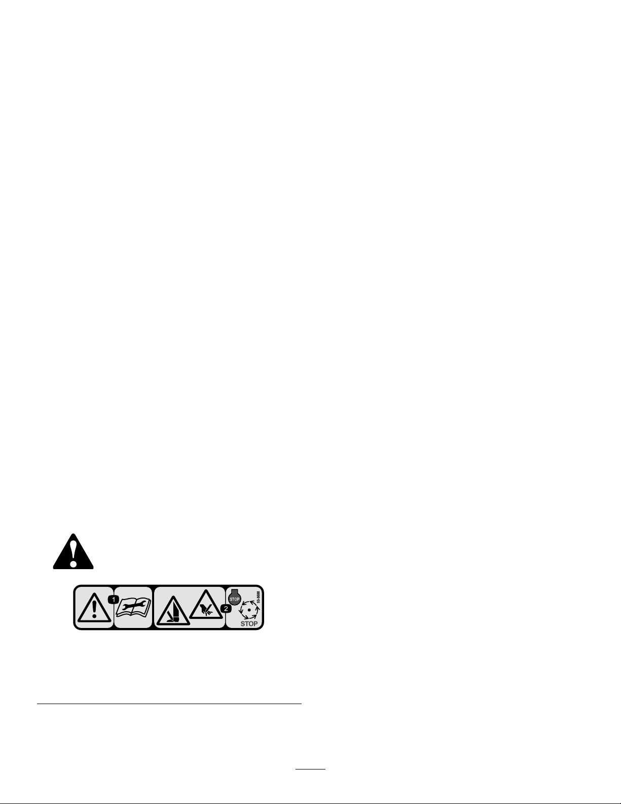
SafetyandInstructionalDecals
Safetydecalsandinstructionsareeasilyvisibletotheoperatorandarelocatednearanyareaof
potentialdanger.Replaceanydecalthatisdamagedorlost.
93-6688
1.Warning—readthe
instructionsbefore
servicingorperforming
maintenance.
2.Cuttinghazardofhandor
foot—stoptheengineand
waitformovingpartsto
stop.
3
Page 4

Setup
LooseParts
Usethechartbelowtoverifythatallpartshavebeenshipped.
ProcedureDescription
1
2
3
4
5
6
7
Cuttingunit
Nopartsrequired
Liftchain5/7
Chainbracket5/7
U-bolt
Nut
Screw5/7
Washer
Nut
Kickstand(suppliedwithtractionunit)
Nopartsrequired
Nopartsrequired
LargeO-ring5/7
Qty.
1Inspectthecuttingunit
–
5/7
10/14
5/7
5/7
1
–
–
Removethetipperassemblies
Mountliftbracketsandchains
Usethekickstandwhentippingthe
cuttingunit
Adjusttherearshield
Mountthecounterweights
Installthecuttingunits.
Use
MediaandAdditionalParts
Description
Partscatalog1
Operator’sManual
CerticateofCompliance
Note:Determinetheleftandrightsidesofthemachine
fromthenormaloperatingposition.
Qty.
Use
1
1
Reviewthematerialandsaveinanappropriateplace:
4
Page 5
1
Inspection
Partsneededforthisprocedure:
1
Cuttingunit
Procedure
Afterthecuttingunitisremovedfromthebox,inspect
thefollowing:
1.Checkeachendofthereelforgrease.Greaseshould
bevisiblyevidentinthereelbearingsandinternal
splinesofthereelshaft.
2.Ensurethatallnutsandboltsaresecurelytightened.
3.Makesurethecarrierframesuspensionoperates
freelyanddoesnotbindwhenmovedbackandforth.
2
RemovingtheTipper
Assemblies
NoPartsRequired
Procedure
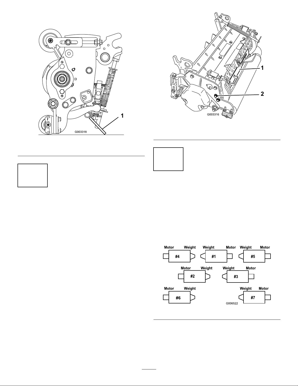
Thetipperassembliesmustberemovedfromthe#1,#2
and#3liftarmstoavoidinterferencewiththecutting
unitcarrierframes.
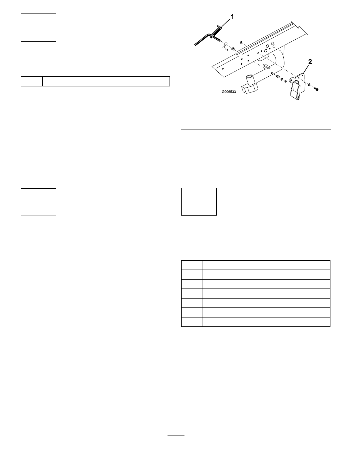
1.Removethelocknutandwashersecuringthepivot
rodtothe#2liftarm(Figure3).Removethe
pivotrodandspringfromtheliftarm.Repeatthe
procedureonthe#1and#3liftarms.
Figure3
1.Pivotrod2.Tippersupportbracket
Note:Thetipperbracketw/rollerandthetipper
supportbracketsarenotrequiredwhenoperating
theDPAcuttingunits(Figure3).Theymaybe
removedifdesired.
2.Disconnecttheliftchainsfromthecuttingunits,if
attached.
w/roller
3
MounttheLiftBracketsand
Chains
Partsneededforthisprocedure:
5/7Liftchain
5/7Chainbracket
U-bolt
5/7
10/14
Procedure
Nut
5/7Screw
Washer
5/7
Nut
5/7
MountachainbrackettoeachliftarmwithaU-boltand
2nuts.Positionthebracketsasfollows:
Note:RefertoFigure10todeterminetheliftarm
numberbeingdescribed.
1.Onliftarms#1,#4and#5,positionthechain
bracketsandU-bolts15inchesbehindthecenter
lineofthepivotknuckle(Figure4).Onliftarms#1
and#5thebracketsshouldberotatedtotheright
10degreesfromvertical(Figure4).Onliftarm#4
5
Page 6
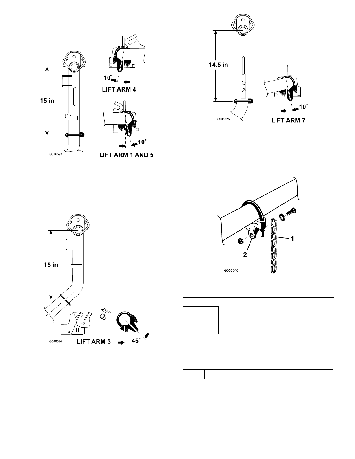
thebracketshouldberotatedtotheleft10degrees
fromvertical(Figure4).
Figure6
4.TightenalltheU-boltnutsto38–48ft-lbs.
Figure4
2.Onliftarms#2and#3,positionthebracketsand
U-bolts15inchesbehindthecenterlineofthepivot
knuckle(Figure5).Rotatethebrackets45degreesto
theoutboardsideofthemachine.
5.Mountaliftchaintoeachchainbracketwithascrew,
washerandnut,positioningasshowninFigure7
Figure7
1.Liftchain2.Chainbracket
Figure5
3.Onliftarms#6and#7,positionthebracketsand
U-bolts14.5inchesbehindthecenterlineofthe
pivotknuckle(Figure6).Rotatethebrackets10
degreestotheoutboardsideofthemachine.
4
CuttingUnitKickstand
Partsneededforthisprocedure:
1
Kickstand(suppliedwithtractionunit)
Procedure
Wheneverthecuttingunithastobetippedtoexposethe
bedknife/reel,propuptherearofthecuttingunitwith
thekickstand(suppliedwiththetractionunit)tomake
6
Page 7
surethenutsonthebackendofthebedbaradjusting
screwsarenotrestingontheworksurface(Figure8).
Figure8
1.Cuttingunitkickstand
1.Rearshield
Figure9
2.Capscrew
5
AdjustingtheRearShield
NoPartsRequired
Procedure
Undermostconditions,bestdispersionisattained
whentherearshieldisclosed(frontdischarge).When
conditionsareheavyorwet,rearshieldmaybeopened.
Toopentherearshield(Figure9),loosenthecapscrew
securingtheshieldtotheleftsideplate,rotatetheshield
totheopenpositionandtightenthecapscrew .
6
MounttheCounterWeights
NoPartsRequired
Procedure
Allcuttingunitsareshippedwiththecounterweight
mountedtotheleftendofthecuttingunit.Usethe
followingdiagramtodeterminethepositionofthe
counterweightsandreelmotors.
Figure10
1.Onthe#2,#4and#6cuttingunits,removethe2
capscrewssecuringthecounterweighttotheleft
endofthecuttingunit.Removethecounterweight
(Figure11).
7
Page 8
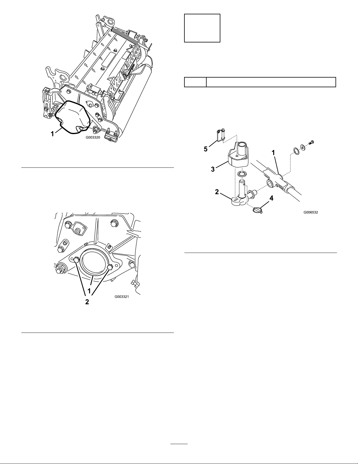
Figure11
1.Counterweight
2.Onrightendofcuttingunit,removetheplasticplug
fromthebearinghousing(Figure12).
3.Removethe2capscrewsfromtherightsideplate
(Figure12).
7
InstallingtheCuttingUnits
Partsneededforthisprocedure:
5/7LargeO-ring
Procedure
1.Insertathrustwasherontohorizontalshaftofpivot
knuckleasshowninFigure13.
Figure12
1.Plasticplug
4.Installthecounterweighttotherightendofthe
cuttingunitwiththe2screwspreviouslyremoved.
5.Looselyinstallthe2reelmotormountingcapscrews
totheleftsideplateofthecuttingunit(Figure12).
2.Capscrew(2)
Figure13
1.Carrierframe
2.Pivotknuckle
3.Liftarmsteeringplate
2.Insertthehorizontalshaftofthepivotknuckleinto
themountingtubeofthecarrierframe(Figure13).
3.Securepivotknuckletocarrierframewithathrust
washer,atwasherandaangeheadcapscrew
(Figure13).
4.Insertathrustwasherontoverticalshaftofpivot
knuckle(Figure13).
5.Ifremoved,inserttheverticalshaftofthepivot
knuckleintoliftarmpivothub(Figure13).Guide
thepivotknuckleinplacebetweenthetworubber
centeringbumpersintheundersideoftheliftarm
steeringplate.
6.Insertthelynchpinintothecrossholeonthepivot
knuckleshaft(Figure13).
7.Securetheliftarmchaintothecuttingunitchain
bracket(Figure14)withthesnapperpinasfollows:
4.Lynchpin
5.Steeringlockingpin
A.Oncuttingunits#1,4,5,6and7,onlyuse6of
thechainlinks.
B.Oncuttingunits#2and3,useall7ofthechain
links.
8
Page 9

Figure14
1.Liftchain2.Snapperpin
8.Coatthesplineofthereelmotorwithcleangrease.
9.OilthereelmotorO-ringandinstallitontothe
motorange.
10.Installthemotorbyrotatingitclockwisesothat
themotorangesclearthecapscrews(Figure15).
Rotatethemotorcounterclockwiseuntiltheanges
encirclethecapscrewsthentightenthecapscrews
Important:Makesurethereelmotorhoses
arenottwisted,kinkedorintheriskofbeing
pinched.
Figure15
1.Reeldrivemotor
2.Capscrew
Note:Ifxedcuttingunitpositionisrequired,
insertsteeringlockingpinintopivotknuckle
mountinghole(Figure13).
11.Hookspringwirearoundbottomofsteeringlocking
pin(Figure13).
9
Page 10

ProductOverview
Specications
Tractors
HeightofCutCuttingheightisadjustedonthefrontrollerbytwoverticalscrewsandheldbytwolocking
HeightOfCutRangeStandardbenchheightofcutrangeis.250inch(3mm)to1.00inch(25mm).Benchheight
ReelWeldment
ReelBearings
PowerAttachment
FrameDiecastaluminumcrossmemberwiththreebolt-ondie-castaluminumsideplates.
Rollers
BedknifeReplaceablesingleedged,highcarbonsteelbedknifeisfastenedtoamachinedcastiron
BedknifeAdjustmentDualscrewadjustmenttothereel;detentscorrespondingto.0009inch(.023mm)bedknife
GrassShieldAdjustablerearshieldwithoptionaladjustablecut-offbartoimprovegrassdischargefrom
Counterweight
MaximumReelSpeed
Weight
ThesecuttingunitswillmountontheReelmaster6500&6700TractionUnits.
capscrews
ofcutrangewiththeHighHeightofCutKitinstalledis1.00inch(25mm)to2.00inches
(51mm).EffectiveHOCmayvarydependingonturfconditions,typeofbedknife,rollers
andattachmentsinstalled.
Reelsare7inches(18cm.)indiameter,22inches(56cm.)inlength.Highstrengthlow
alloysteelbladesarethruhardenedandimpactresistant.
Twodoublerowself-aligningballbearings,presstontoreelshaft.
Thereelmotorsfeaturequickdisconnectforremovalorinstallationontocuttingunit.The
cuttingunitscanbedrivenfromeitherend.
Thefrontrollerisa3inch(76mm)diameterplasticWiehleroller .Therearrollerisa3.0inch
(76mm)diametersteelfullroller.
bedbarwith8screws.TheEdgeMaxt®bedknifeisstandard.
movementforeachindexedposition.
reelinwetconditions.
Acastironweightmountedoppositetothedrivemotorbalancesthecuttingunit.
1650RPM.
8Blade147lb.(67kg)11Blade151lb.(69kg)
10
Page 11

CuttingUnitAccessoriesandKits(see
partscatalogforpartnumbers)
Note:Allaccessoriesandkitsare1percuttingunit
unlessotherwisespecied.
GrassBasketKit:Aseriesofclippingcollection
basketsattachedtothefrontofthecuttingunitsto
collectgrassclippings.
RearLiftCylinderKit:Ahighspeed,highcontact
brushthatkeepstherearrollerfreeofgrassanddebris,
whichmaintainsaconsistentheightofcutandprevents
clumping.Thisleadstoabetteraftercutappearance.
RearRollerBrushKit:Ahighspeed,highcontact
brushthatkeepstherearrollerfreeofgrassanddebris,
whichmaintainsaconsistentheightofcutandprevents
clumping.Thisleadstoabetterafter-cutappearance.
GroomerKit:Rotatingbladesassembledbehindthe
frontrollerwhichprovidethebestmethodforreducing
grainandspongyturfbystandingupthegrassbefore
cutting.Thegroomeralsoknocksoffdewfordecreased
stickinessandclumping,opensupcanopyforbetter
grassclippingintegration,andliftsgrassforaclean
crispcut.Theoveralldesignimprovesthequalityofcut
forhealthierturfgrasswhileimprovingtheaftercut
appearance
BroomerKit:Multiplebrushstripswovenintothe
helicalgroomerbladesimprovetheeffectivenessofthe
groomerkit.Performanceofthegroomerisenhanced
byenablingafullwidth"Brooming"effectofturfwhile
openingupcanopyforbettergrassclippingintegration.
Thecombinationofgroomerandbroomersystems
optimizethequalityofcutandafter-cutappearancefor
moreconsistentplayingconditions.
Comb/ScraperKit:Axedcombinstalledbehindthe
frontrollerwhichhelpsreducegrainandspongyturfby
standingupthegrassbeforecutting.Ascraperforthe
frontWiehlerollerisincludedinthekit.
HighHOCKit:Newfrontrollerbracketsand
additionalspacersfortherearrollerallowsthecutting
unittoachieveheightsofcutabove1.00inch(25mm).
Thenewfrontrollerbracketsalsomovethefrontroller
outfarthertoimproveafter-cutappearance.
ShoulderRoller:Helpsreduceover-lapmarksfor
warmseasongrasses(Bermuda,Zoysia,Paspalum).
CollarKit(6perrollerrequired):Helpsreduceover
lapmarksforwarmseasongrasses(Bermuda,Zoysia,
Paspalum).ThiskitisinstalledontheexistingWiehle
roller,butisnotasaggressiveastheShoulderroller.
ShortRearRoller:Helpsreducedoublerollermarks
forcoolseasongrasses(Bent,Bluegrass,Rye).
FullFrontRoller:Helpsproducemorepronounced
striping(repeatedcuttinginthesamedirection/path),
however,effectiveheightofcutisraisedandqualityof
cutisreduced.
Scrapers(Wiehle,Shoulder,Rearroller,FullFront
Roller):Fixedscrapersforalloptionalrollersare
availableforreducinggrassbuilduponrollerswhich
canaffectheightofcutsettings.
RollerRebuildKit:Includesallthebearings,bearing
nuts,innersealsandoutersealsrequiredtorebuilda
roller.
RollerRebuildT oolKit:Includesallthetoolsand
installationinstructionsrequiredtorebuildarollerwith
therollerrebuildkit.
11
Page 12

Operation
Note:Determinetheleftandrightsidesofthe
machinefromthenormaloperatingposition.
Adjustments
AdjustingtheBedknifetotheReel
Bedknifetoreeladjustmentisaccomplishedby
looseningortighteningbedbaradjustingscrews,located
ontopofmower.
1.Positionmachineonaat,levelworksurface.Make
surereelcontactisremovedbyturningbedbar
adjustingscrewscounterclockwise(Figure16).
Figure16
1.Bedbaradjustingscrew
2.Tiltmoweronback,ontothecuttingunitkickstand,
toexposebedknifeandreel.
Important:Makesurenutsonbackendof
bedbaradjustingscrewsarenotrestingonthe
worksurface(Figure16).
Figure17
4.Checkforlightcontactatotherendofreelusing
paperandadjustasrequired.
5.Afteradjustmentisaccomplished,checktoseeif
reelcanpinchpaperwheninsertedfromthefront
andcutpaperwheninsertedatarightangletothe
bedknife(Figure17).Itshouldbepossibletocut
paperwithminimumcontactbetweenthebedknife
andthereelblades.Ifexcessivecontact/reeldrag
isevidentitwillbeeithernecessarytobacklapor
regrindthecuttingunittoachievethesharpedges
neededforprecisioncutting(RefertotheToro
manualforSharpeningReelandRotaryMowers,
FormNo.80-300PT).
AdjustingtheRearRoller
1.Adjusttherearrollerbrackets(Figure18)tothe
desiredheightofcutrangebypositioningthe
requiredamountofspacersbelowthesideplate
mountingange(Figure18)pertheHOCChart.
3.Atoneendofreel,insertastripofnewspaper
betweenreelandbedknife(Figure17).Whileslowly
rotatingreelforward,turnbedbaradjustingscrew
(Figure16)clockwiseonsameendofreel,one
clickatatime,untilpaperispinchedlightly,when
insertedfromthefront,paralleltothebedknife.A
slightdragwillbenotedasthepaperispulled.
Note:Eachtimeadjustingscrewisrotatedone
clickclockwise,bedknifemoves.0009in(.023mm).
closertoreel.Donotovertightentheadjusting
screws.
Figure18
1.Spacer3.Sideplatemountingange
2.Rollerbracket
2.Raiserearofcuttingunitandplaceablockunder
bedknife.
3.Remove(2)nutssecuringeachrollerbracketand
spacertoeachsideplatemountingange.
4.Lowerrollerandscrewsfromsideplatemounting
angesandspacers.
5.Placespacersontoscrewsonrollerbrackets.
12
Page 13

6.Re-securerollerbracketandspacerstounderside
ofsideplatemountingangeswithnutspreviously
removed.
7.Verifythatbedknifetoreelcontactiscorrect.Tip
mowertoexposefrontandrearrollersandbedknife.
Note:Thepositionoftherearrollertothe
reeliscontrolledbythemachiningtolerances
oftheassembledcomponentsandparallelingis
notrequired.Alimitedamountofadjustmentis
possiblebysettingthecuttingunitonasurface
plateandlooseningthesideplatemountingcap
screws(Figure19).Adjustandretightencapscrews.
Torquethecapscrewsto27-33ft-lb.
Paspalum,Zoysia)whilecoolseasongrasses(Bent,
Bluegrass,Rye)mayrequirenormaltomoreaggressive
setups.Moreaggressivesetupscutmoregrassoffby
allowingthespinningreeltopullmoregrassupinto
thebedknife.
Figure20
1.Rearspacers
2.Sideplatemountingange
3.Aggressivenessofcut
Figure19
1.Sideplatemountingcapscrews
HeightofCutChartTerms
HeightofCutSetting(HOC)
ThedesiredHeightofCut.
AggressivenessofCut
CuttingunitAggressivenessofCuthasasignicant
impactontheperformanceofthecuttingunit.
AggressivenessofCutreferstotheangleofthe
bedkniferelativetotheground(Figure20).
RearSpacers
Thenumberofrearspacersdeterminesthe
aggressivenessofcutforthecuttingunit.Foragiven
heightofcut,addingspacers,belowthesideplate
mountingange,increasestheaggressivenessofthe
cuttingunit.Allcuttingunitsonagivenmachinemust
besettothesameaggressivenessofcut(Numberof
rearspacers,partno.106-3925),otherwisetheafter-cut
appearancecouldbenegativelyaffected(Figure20).
Groomer
Thesearetherecommendedheightofcutsettings
whenagroomerkitisinstalledonthecuttingunit.
Thebestcuttingunitsetupisdependentonyour
turfconditionsanddesiredresults.Experiencewith
thecuttingunitonyourturfwilldeterminethebest
settingtouse.Aggressivenessofcutmaybeadjusted
throughoutthecuttingseasontoallowforvariousturf
conditions.
Ingeneral,lesstonormalaggressivesettingsare
moreappropriateforwarmseasongrasses(Bermuda,
13
Page 14

HeightofCutChart
HOCSettingAggressivenessofCutNo.ofRearSpacersWithGroomerkitsinstalled
0.250"Less
0.375"Less
0.500"Less
0.625"Less
0.750"Less
0.875"Less
1.000"Less
1.125"Less
1.250"*+
1.375"*+
1.500"*+
1.625"*+
1.750"*+
1.875"*+
2.000"*+
*HighHOCKit(PartNo.110-9600)mustbeinstalled.FrontHOCbracketmustbepositionedinthetopsideplatehole.
+WhentheHeightofCutisabove1inchandarearrollerbrushisused,theHighHeightofCutBrushisrequiredandtheoptional
SteeringCylinder,PartNo.105–9275shouldbeinstalledtopreventcontactbetweenthereartireandthebrushwhenmaking
extremeturns.
Normal
More
Normal
More
Normal
More
Normal
More
Normal
More
Normal
More
Normal
More
Normal
More
Less
Normal
More
Less
Normal
More
Less
Normal
More
Less
Normal
More
Less
Normal
More
Less
Normal
More
Less
Normal
More
0
0
1
0
1
2
0
1
2
1
2
3
2
3
4
2
3
4
3
4
5
4
5
6
4
5
6
4
5
6
5
6
7
6
7
8
6
7
8
7
8
9
7
8
9
Y
Y
-
Y
Y
-
Y
Y
Y
Y
Y
-
Y
Y
-
Y
Y
-
Y
Y
-
-
-
-
-
-
-
-
-
-
-
-
-
-
-
-
-
-
-
-
-
-
-
-
-
14
Page 15

AdjustingtheHeightofCut
Note:Forheightsofcutgreaterthan1.00"theHigh
HeightofCutKitmustbeinstalled.
1.Loosenlocknutssecuringheight-of-cutarmsto
cuttingunitsideplates(Figure21).
Figure23
Figure21
1.Height-of-cutarm
2.Locknut
3.Adjustingscrew
2.Loosennutongaugebar(Figure22)andset
adjustingscrewtodesiredheight-of-cut.Distance
betweenbottomofscrewheadandfaceofbaris
height-of-cut.
Figure22
1.Gaugebar4.Holesusedforsetting
2.Heightadjustingscrew5.Holenotused
3.Nut
GroomerHOG
Important:Whensetproperly,therearand
frontrollerswillcontactthegaugebarandthe
screwwillbesnugagainstthebedknife.This
ensuresthattheheight-of-cutisidenticalat
bothendsofthebedknife.
5.Tightennutstosecureadjustment.Donot
overtightennut.Tightenenoughtoremoveplay
fromwasher.
Usethefollowingcharttodeterminewhich
bedknifeisbestsuitedforthedesiredheightofcut.
Bedknife/HeightofCutChart
Bedknife
LowHOC
(Optional)
EdgeMaxt®
(Production)
Standard
(Optional)
HD(Optional)
PartNo.
110-4084.220”.250-.375"
108-9095.270”.375-1.50"
108-9096.270”.375-2.0"
110-4074.370”.500-2.0"
BedknifeLip
Height*
HeightofCut
3.Hookthescrewheadoncuttingedgeofbedknife
andrestrearendofbaronrearroller(Figure23).
4.Rotatetheadjustingscrewuntilthefrontroller
contactsthegaugebar(Figure23).Adjustbothends
ofrolleruntilentirerollerisparalleltothebedknife.
Figure24
1.BedknifeLipHeight*
15
Page 16

CuttingUnitCharacteristics
Thedualknobbedknife-to-reeladjustmentsystem
incorporatedinthiscuttingunitsimpliesthe
adjustmentprocedureneededtodeliveroptimum
mowingperformance.Thepreciseadjustment
possiblewiththedualknob/bedbardesigngivesthe
necessarycontroltoprovideacontinualself-sharpening
action-thusmaintainingsharpcuttingedges,ensuring
goodquality-of-cut,andgreatlyreducingtheneedfor
routinebacklapping.
DailyAdjustmentsofCuttingUnit
Priortomowingeachday,orasrequired,eachcutting
unitmustbecheckedtoverifyproperbedknife-to-reel
contact.Thismustbeperformedeventhough
qualityofcutisacceptable.
1.Lowerthecuttingunitsontoahardsurface,shutoff
theengine,andremovetheignitionkey.
2.Slowlyrotatethereelinareversedirection,
listeningforreel-to-bedknifecontact.Ifnocontact
isevident,turnthebedknifeadjustingknobs
clockwise,oneclickatatime,untillightcontactis
feltandheard.
Note:Theadjustmentknobshavedetents
correspondingto0.0009in.(0.023mm)bedknife
movementforeachindexedposition.
3.Ifexcessivecontactisfelt,turnthebedknife
adjustingknobscounterclockwise,oneclickat
atimeuntilnocontactisevident.Thenturn
thebedknifeadjustingknobsoneclickatatime
clockwise,untillightcontactisfeltandheard.
Important:Lightcontactispreferredatall
times.Iflightcontactisnotmaintained,
thebedknife/reeledgeswillnotsufciently
self-sharpenanddullcuttingedgeswillresult
afteraperiodofoperation.Ifexcessivecontact
ismaintained,bedknife/reelwearwillbe
accelerated,unevenwearcanresult,andquality
ofcutmaybeadverselyaffected.
Note:Overtime,thechamfer(Figure25)willneed
toberegroundasitisonlydesignedtolast40%
ofthebedknifelife.
Figure25
1.Lead-inchamferonrightendofbedknife
Note:Donotmakelead-inchamfertoolargeas
itmaycauseturftufting.
ServicingBedknife
Thebedknifeservicelimitsarelistedinthefollowing
charts.
Important:Operatingthecuttingunitwiththe
bedknifebelowthe“servicelimit”mayresultin
poorafter-cutappearanceandreducethestructural
integrityofthebedknifeforimpacts.
BedknifeServiceLimitChart
Bedknife
LowHOC
(Optional)
EdgeMax®
(Production)
Standard
(Optional)
HeavyDuty
(Optional)
PartNo.
110-4084.220.190"
108-9095.270.190"
108-9096.270.190"
110-4074.370.190"
BedknifeLip
Height*
ServiceLimit
*
Note:Asthereelbladescontinuetorunagainst
thebedknife,aslightburrwillappearonthefront
cuttingedgesurfacealongthefulllengthofthe
bedknife.Ifaleisoccasionallyrunacrossthe
frontedgetoremovethisburr,improvedcutting
canbeobtained.
Afterextendedrunning,aridgewilleventually
developatbothendsofthebedknife.Thesenotches
mustberoundedofforledushwiththecutting
edgeofthebedknifetoensuresmoothoperation.
16
Page 17

Note:Therecommendedtopandfrontbedknifegrind
angleis3to7degrees(Figure26).
Figure26
1.Bedknifeservicelimit*
Note:Allbedknifeservicelimitmeasurements
referencethebottomofthebedknife(Figure27)
Figure27
17
Page 18

Maintenance
Lubrication
Eachcuttingunithas(6)greasettings(Figure28)that
mustbelubricatedregularlywithNo.2GeneralPurpose
LithiumBaseGrease.
Thelubricationpointsarefrontroller(2),rearroller(2)
andreelbearing(2).
Note:Lubricatingcuttingunitsimmediatelyafter
washinghelpspurgewateroutofbearingsand
increasesbearinglife.
1.Wipeeachgreasettingwithacleanrag.
2.Applygreaseuntilcleangreaseisseencomingoutof
rollersealsandbearingreliefvalve.
3.Wipeexcessgreaseaway .
Figure29
1.Bedknifeadjustingknob
2.Usingaragorthicklypaddedglove,holdontothe
reelbladeandtrytomovethereelassemblysideto
side(Figure30).
Figure28
1.Reliefvalve
AdjustingtheReelBearings
Toensurelonglifeofthereelbearings,periodically
checkifreelendplayexists.Thereelbearingscanbe
checkedandadjustedasfollows:
1.Loosenreeltobedknifecontactbyturning
thebedknifeadjustingknobs(Figure29)
counterclockwiseuntilnocontactexists.
Figure30
3.Ifendplayexists,proceededasfollows:
A.Loosenexternalsetscrewsecuringbearing
adjustingnuttobearinghousinglocatedonthe
leftsideofthecuttingunit(Figure31).
Figure31
B.Usinga1-3/8"socketwrench,slowlytightenthe
reelbearingadjustmentnutuntilnoendplayof
thereelexists.Ifadjustingnutdoesnoteliminate
reelendplay,replacereelbearings.
18
Page 19

Note:Reelbearingsdonotrequirepreload.
Overtighteningreelbearingadjusternutwill
damagereelbearings.
4.Retightensetscrewsecuringbearingadjustingnutto
bearinghousing.Torqueto12-15in-lb.
ServicingtheBedbar
RemovingtheBedbar
1.Turnbedbaradjusterscrews,counterclockwise,to
backbedknifeawayfromreel(Figure32).
Figure32
1.Bedbaradjustingscrew3.Bedbar
2.Springtensionnut
2.Backoutthespringtensionnut,untilthewasheris
nolongertensionedagainstthebedbar(Figure32).
3.Oneachsideofthemachine,loosenthelocknut
securingthebedbarbolt(Figure33).
4.Washer
Figure34
1.Bedbarbolt
2.Nut4.Nylonwasher
3.Steelwasher
AssemblingtheBedbar
1.Installbedbar,positioningmountingearsbetween
washerandbedbaradjuster.
2.Securebedbartoeachsideplatewithbedbarbolts
(nutsonbolts)and6washers.Anylonwasheristo
bepositionedoneachsideofsideplateboss.Place
asteelwasheroutsideeachofthenylonwashers
(Figure34).Torquebedbarboltsto27-33ft.-lb.
Tightenlocknutsuntiltheoutsidesteelwasher
stopsrotatingandendplayisremovedbutdonot
overtightenordeectsideplates.W ashersoninside
mayhaveagap.
Figure33
1.Bedbarbolt2.Locknut
4.Removeeachbedbarboltallowingbedbartobe
pulleddownwardandremovedfrommachinebolt
(Figure33).Accountfor2nylonand1stampedsteel
washersoneachendofbedbar(Figure34).
3.Tightenspringtensionnutuntilspringiscollapsed,
thenbackoff1/2turn(Figure35).
Figure35
1.Springtensionnut2.Spring
19
Page 20

ServicingtheRoller
ARollerRebuildKit,PartNo.114–5430andaRoller
RebuildToolKit,PartNo.115–0803(Figure36)
areavailableforservicingtheroller.TheRoller
RebuildKitincludesallthebearings,bearingnuts,
innersealsandoutersealstorebuildaroller.
TheRollerRebuildT oolKitincludesallthetoolsand
theinstallationinstructionsrequiredtorebuildaroller
withtherollerrebuildkit.Refertoyourpartscatalogor
contactyourdistributorforassistance.
Figure36
1.Rebuildkit(PartNo.114–5430)
2.Rebuildtoolkit(PartNo.115–0803)
3.Innerseal8.Washer
4.Bearing
5.Outerseal
6.Bearingnut
7.Innersealtool
9.Bearing/outersealtool
20
Page 21

Notes:
21
Page 22

Notes:
22
Page 23

Notes:
23
Page 24

The Toro General Commercial Products Warranty
A Two-Year Limited Warranty
Conditions and Products Covered
The Toro Company and its affiliate, Toro Warranty Company,
pursuant to an agreement between them, jointly warrant your Toro
Commercial Product (“Product”) to be free from defects in
materials or workmanship for two years or 1500 operational
hours*, whichever occurs first. Where a warrantable condition
exists, we will repair the Product at no cost to you including
diagnosis, labor, parts, and transportation. This warranty begins
on the date the Product is delivered to the original retail purchaser.
* Product equipped with hour meter
Instructions for Obtaining Warranty Service
You are responsible for notifying the Commercial Products
Distributor or Authorized Commercial Products Dealer from whom
you purchased the Product as soon as you believe a warrantable
condition exists.
If you need help locating a Commercial Products Distributor or
Authorized Dealer, or if you have questions regarding your
warranty rights or responsibilities, you may contact us at:
Toro Commercial Products Service Department
Toro Warranty Company
8111 Lyndale Avenue South
Bloomington, MN 55420-1196
952-888-8801 or 800-982-2740
E-mail: commercial.service@toro.com
Owner Responsibilities
As the Product owner, you are responsible for required maintenance and adjustments stated in your operator’s manual. Failure
to perform required maintenance and adjustments can be grounds
for disallowing a warranty claim.
Items and Conditions Not Covered
Not all product failures or malfunctions that occur during the
warranty period are defects in materials or workmanship. This
express warranty does not cover the following:
• Product failures which result from the use of non-Toro
replacement parts, or from installation and use of add-on,
modified, or unapproved accessories
• Product failures which result from failure to perform required
maintenance and/or adjustments
• Product failures which result from operating the Product in an
abusive, negligent or reckless manner
• Parts subject to consumption through use unless found to be
defective. Examples of parts which are consumed, or used up,
during normal Product operation include, but are not limited to,
blades, reels, bedknives, tines, spark plugs, castor wheels,
tires, filters, belts, and certain sprayer components such as
diaphragms, nozzles, and check valves, etc.
• Failures caused by outside influence. Items considered to be
outside influence include, but are not limited to, weather,
storage practices, contamination, use of unapproved coolants,
lubricants, additives, or chemicals, etc.
• Normal “wear and tear” items. Normal “wear and tear” includes,
but is not limited to, damage to seats due to wear or abrasion,
worn painted surfaces, scratched decals or windows, etc.
Parts
Parts scheduled for replacement as required maintenance are
warranted for the period of time up to the scheduled replacement
time for that part.
Parts replaced under this warranty become the property of Toro.
Toro will make the final decision whether to repair any existing part
or assembly or replace it. Toro may use factory remanufactured
parts rather than new parts for some warranty repairs.
General Conditions
Repair by an Authorized Toro Distributor or Dealer is your sole
remedy under this warranty.
Neither The Toro Company nor Toro Warranty Company is
liable for indirect, incidental or consequential damages in
connection with the use of the Toro Products covered by this
warranty, including any cost or expense of providing substitute equipment or service during reasonable periods of
malfunction or non-use pending completion of repairs under
this warranty. Except for the Emissions warranty referenced
below, if applicable, there is no other express warranty. All
implied warranties of merchantability and fitness for use are
limited to the duration of this express warranty.
Some states do not allow exclusions of incidental or consequential
damages, or limitations on how long an implied warranty lasts, so
the above exclusions and limitations may not apply to you.
This warranty gives you specific legal rights, and you may also
have other rights which vary from state to state.
Note regarding engine warranty: The Emissions Control System
on your Product may be covered by a separate warranty meeting
requirements established by the U.S. Environmental Protection
Agency (EPA) and/or the California Air Resources Board (CARB).
The hour limitations set forth above do not apply to the Emissions
Control System Warranty. Refer to the Engine Emission Control
Warranty Statement printed in your operator’s manual or contained in the engine manufacturer’s documentation for details.
Countries Other than the United States or Canada
Customers who have purchased Toro products exported from the United States or Canada should contact their Toro Distributor (Dealer)
to obtain guarantee policies for your country, province, or state. If for any reason you are dissatisfied with your Distributor’s service or
have difficulty obtaining guarantee information, contact the Toro importer. If all other remedies fail, you may contact us at Toro Warranty
Company.
Part No. 374-0031 Rev. C
 Loading...