

Page 1
FormNo.3375-301RevC
Reelmaster
®
6500-Dand6700-D
TractionUnit
ModelNo.03806—SerialNo.313000001andUp
ModelNo.03807—SerialNo.313000001andUp
ModelNo.03808—SerialNo.313000001andUp
ModelNo.03812—SerialNo.313000001andUp
ModelNo.03813—SerialNo.313000001andUp
ToregisteryourproductordownloadanOperator'sManualorPartsCatalogatnocharge,gotowww.T oro.com.OriginalInstructions(EN)
Page 2

ThisproductcomplieswithallrelevantEuropean
directives,fordetailspleaseseetheseparateproduct
specicDeclarationofConformity(DOC)sheet.
WARNING
CALIFORNIA
Proposition65Warning
Dieselengineexhaustandsomeofits
constituentsareknowntotheStateof
Californiatocausecancer,birthdefects,
andotherreproductiveharm.
Figure1
Important:Thisengineisnotequippedwitha
sparkarrestermufer.ItisaviolationofCalifornia
PublicResourceCodeSection4442touseoroperate
theengineonanyforest-covered,brush-covered,or
grass-coveredland.Otherstatesorfederalareas
mayhavesimilarlaws.
Introduction
Thismachineisaride-on,reel-bladelawnmower
intendedtobeusedbyprofessional,hiredoperatorsin
commercialapplications.Itisprimarilydesignedfor
cuttinggrassonwell-maintainedlawnsinparks,golf
courses,sportselds,andoncommercialgrounds.Itis
notdesignedforcuttingbrush,mowinggrassandother
growthalongsidehighways,orforagriculturaluses.
Readthisinformationcarefullytolearnhowtooperate
andmaintainyourproductproperlyandtoavoidinjury
andproductdamage.Youareresponsibleforoperating
theproductproperlyandsafely.
YoumaycontactTorodirectlyatwww .Toro.comfor
productandaccessoryinformation,helpndingadealer,
ortoregisteryourproduct.
1.Locationofthemodelandserialnumbers
ModelNo.
SerialNo.
Thismanualidentiespotentialhazardsandhassafety
messagesidentiedbythesafetyalertsymbol(Figure2),
whichsignalsahazardthatmaycauseseriousinjury
ordeathifyoudonotfollowtherecommended
precautions.
Figure2
1.Safetyalertsymbol.
Thismanualusestwootherwordstohighlight
information.Importantcallsattentiontospecial
mechanicalinformationandNoteemphasizesgeneral
informationworthyofspecialattention.
Wheneveryouneedservice,genuineToroparts,
oradditionalinformation,contactanAuthorized
ServiceDealerorToroCustomerServiceandhave
themodelandserialnumbersofyourproductready.
Figure1identiesthelocationofthemodelandserial
numbersontheproduct.Writethenumbersinthe
spaceprovided.
©2013—TheT oro®Company
8111LyndaleAvenueSouth
Bloomington,MN55420
Contactusatwww.Toro.com.
2
PrintedintheUSA.
AllRightsReserved
Page 3

Contents
Introduction.................................................................2
Safety...........................................................................4
SafeOperatingPractices.......................................4
ToroMowerSafety...............................................5
SoundPowerLevel...............................................6
SoundPowerLevel...............................................6
SoundPressureLevel...........................................6
VibrationLevel....................................................6
SafetyandInstructionalDecals.............................7
Setup.........................................................................14
1CheckingFluidLevels......................................14
2InstallingCuttingUnitsModels03860,03861
and03862.......................................................14
3InstallingCuttingUnitsModels03863and
03864.............................................................16
4MakingAlternateCuttingUnit
Adjustments...................................................21
5AddingRearBallast..........................................21
6InstallingCEDecals........................................21
7ReadingtheManualsandStoringAdditional
Parts...............................................................21
ProductOverview......................................................22
Controls.............................................................22
Specications.....................................................25
Attachments/Accessories...................................25
Operation...................................................................26
CheckingtheEngineOil.....................................26
CheckingtheCoolingSystem..............................26
FillingtheFuelTank...........................................27
CheckingtheHydraulicFluid..............................29
CheckingtheTirePressure.................................30
CheckingtheReeltoBedknifeContact................30
StartingandStopping.........................................30
BleedingtheFuelSystem....................................30
PushingorTowingtheMachine..........................31
CheckingtheInterlockSwitches.........................31
FaultMemoryandRetrieval................................33
HydraulicSolenoidValveFunctions....................33
OperatingTips...................................................34
Maintenance...............................................................35
RecommendedMaintenanceSchedule(s)................35
ServiceIntervalChart.........................................36
DailyMaintenanceChecklist...............................37
Lubrication.............................................................38
GreasingtheBearingsandBushings....................38
EngineMaintenance...............................................40
ServicingtheAirCleaner....................................40
ServicingtheEngineOilandFilter......................41
AdjustingThrottle..............................................41
FuelSystemMaintenance.......................................42
FuelTank...........................................................42
FuelLinesandConnections................................42
FuelFilter/WaterSeparator................................42
BleedingAirFromInjectors...............................43
ElectricalSystemMaintenance................................43
BatteryCare.......................................................43
Fuses..................................................................44
OptionalLighting...............................................44
DriveSystemMaintenance.....................................46
CheckingtheTorqueoftheWheelNutsor
Bolts..............................................................46
CheckingthePlanetaryGearDrive
Oil..................................................................46
ChangingthePlanetaryGearDrive
Oil..................................................................46
CheckingtheRearAxleLubricant.......................47
ChangingtheRearAxleLubricant.......................47
RearWheelT oe-In.............................................48
AdjustingtheTractionDriveforNeutral.............48
CoolingSystemMaintenance..................................49
RemovingDebris...............................................49
MaintainingtheCoolingSystem..........................49
BrakeMaintenance.................................................50
AdjustingtheServiceBrakes...............................50
BeltMaintenance....................................................50
CheckingtheAlternatorBelt...............................50
HydraulicSystemMaintenance...............................51
ChangingtheHydraulicFluid.............................51
ReplacingtheHydraulicFilter.............................51
CheckingtheHydraulicLinesandHoses.............51
HydraulicSystemTestPorts...............................52
CuttingUnitMaintenance.......................................53
CuttingUnitKickstandModels03863and
03864.............................................................53
Backlapping........................................................53
AdjustingtheCuttingUnitLoweringRate
......................................................................54
LiftedHeightofOuterFrontCuttingUnits
(EnablePosition)............................................55
AdjustingtheTraveloftheFrontThree
CuttingUnits..................................................56
Storage.......................................................................57
TractionUnit......................................................57
Engine...............................................................57
Schematics.................................................................58
3
Page 4

Safety
ThismachinemeetsorexceedsCENstandard
EN836:1997,ISOstandard5395:1990,andANSI
B71.4-2004specicationsineffectatthetimeof
productionwhenballastisadded;refertoAdding
RearBallastinSetUpsection.
Note:Theadditionofattachmentsmadeby
othermanufacturersthatdonotmeetAmerican
NationalStandardsInstitutecerticationwillcause
noncomplianceofthismachine.
•Inspecttheareawheretheequipmentistobeused
andremoveallobjectssuchasrocks,toysandwire
whichcanbethrownbythemachine.
•Useextracarewhenhandlingdieselfuel.Itis
ammableandvaporsareexplosive.
Useonlyanapprovedcontainer.
•Neverremovegascaporaddfuelwithengine
running.Allowenginetocoolbeforerefueling.Do
notsmoke.
•Neverrefuelordrainthemachineindoors.
Improperuseormaintenancebytheoperatororowner
canresultininjury.Toreducethepotentialforinjury,
complywiththesesafetyinstructionsandalwayspay
attentiontothesafetyalert
CAUTION,WARNING,orDANGER-“personalsafety
instruction.”Failuretocomplywiththeinstructionmay
resultinpersonalinjuryordeath.
symbol,whichmeans
SafeOperatingPractices
ThefollowinginstructionsarefromtheCENstandard
EN836:1997,ISOstandard5395:1990,andANSI
B71.4-2004.
Training
•ReadtheOperator'sManualandothertraining
material.Iftheoperator(s)ormechanic(s)cannot
readEnglishitistheowner'sresponsibilitytoexplain
thismaterialtothem.
•Becomefamiliarwiththesafeoperationofthe
equipment,operatorcontrols,andsafetysigns.
•Alloperatorsandmechanicsshouldbetrained.The
ownerisresponsiblefortrainingtheusers.
•Neverletchildrenoruntrainedpeopleoperateor
servicetheequipment.Localregulationsmayrestrict
theageoftheoperator.
•Theowner/usercanpreventandisresponsiblefor
accidentsorinjuriesoccurringtohimselforherself,
otherpeopleorproperty.
•Checkthatoperator'spresencecontrols,safety
switchesandshieldsareattachedandfunctioning
properly.Donotoperateunlesstheyarefunctioning
properly.
Operation
•Neverrunanengineinanenclosedarea.
•Onlyoperateingoodlight,keepingawayfromholes
andhiddenhazards.
•Besurealldrivesareinneutralandparkingbrakeis
engagedbeforestartingengine.Onlystartengine
fromtheoperator'sposition.Alwaysuseseatbelts
whenROPSisprovided.
•Slowdownanduseextracareonhillsides.Besure
totravelintherecommendeddirectiononhillsides.
Turfconditionscanaffectthemachine'sstability.
Usecautionwhileoperatingneardrop-offs.
•Slowdownandusecautionwhenmakingturnsand
whenchangingdirectionsonslopes.
•Neveroperatewithguardsnotsecurelyinplace.Be
sureallinterlocksareattached,adjustedproperly,
andfunctioningproperty.
•Donotchangetheenginegovernorsettingor
overspeedtheengine.
•Stoponlevelground,raisethecuttingunits,
disengagedrives,engageparkingbrake(ifprovided),
shutoffenginebeforeleavingtheoperator'sposition
foranyreasonincludingemptyingthegrassbaskets.
Preparation
•Evaluatetheterraintodeterminewhataccessories
andattachmentsareneededtoproperlyand
safelyperformthejob.Onlyuseaccessoriesand
attachmentsapprovedbythemanufacturer.
•Wearappropriateclothingincludinghardhat,safety
glassesandearprotection.Longhair,looseclothing
orjewelrymaygettangledinmovingparts.
•Stopequipmentandinspectthemachineafter
strikingobjectsorifanabnormalvibrationoccurs.
Makenecessaryrepairsbeforeresumingoperations.
•Keephandsandfeetawayfromthecuttingunits.
•Lookbehindanddownbeforebackinguptobesure
ofaclearpath.
•Nevercarrypassengersandkeeppetsandbystanders
away.
4
Page 5

•Slowdownandusecautionwhenmakingturns
andcrossingroadsandsidewalks.Stopreelsifnot
mowing.
•Donotoperatethemowerundertheinuenceof
alcoholordrugs.
•Lightningcancausesevereinjuryordeath.If
lightningisseenorthunderisheardinthearea,do
notoperatethemachine;seekshelter.
•Usecarewhenloadingorunloadingthemachine
intoatrailerortruck.
ToroMowerSafety
Thefollowinglistcontainssafetyinformationspecicto
Toroproductsorothersafetyinformationthatyoumust
knowthatisnotincludedintheANSIstandards.
Thisproductiscapableofamputatinghandsand
feetandthrowingobjects.Alwaysfollowallsafety
instructionstoavoidseriousinjuryordeath.
Useofthisproductforpurposesotherthanitsintended
usecouldprovedangeroustouserandbystanders.
•Usecarewhenapproachingblindcorners,shrubs,
trees,orotherobjectsthatmayobscurevision.
MaintenanceandStorage
•Disengagedrives,raisethecuttingunits,setparking
brake,stopengineandremovekey.Waitforall
movementtostopbeforeadjusting,cleaningor
repairing.
•Cleangrassanddebrisfromcuttingunits,drives,
mufers,andenginetohelppreventres.Cleanup
oilorfuelspillage.
•Letenginecoolbeforestoringanddonotstorenear
ame.
•Shutofffuelwhilestoringortransporting.Donot
storefuelnearamesordrainindoors.
•Parkmachineonlevelground.Neverallowuntrained
personneltoservicemachine.
•Usejackstandstosupportcomponentswhen
required.
•Carefullyreleasepressurefromcomponentswith
storedenergy.
•Disconnectbatterybeforemakinganyrepairs.
Disconnectthenegativeterminalrstandthe
positivelast.Reconnectpositiverstandnegative
last.
•Usecarewhencheckingthereels.W earglovesand
usecautionwhenservicingthem.
•Keephandsandfeetawayfrommovingparts.If
possible,donotmakeadjustmentswiththeengine
running.
•Chargebatteriesinanopenwellventilatedarea,
awayfromsparkandames.Unplugchargerbefore
connectingordisconnectingfrombattery.W ear
protectiveclothinganduseinsulatedtools.
•Keepallpartsingoodworkingconditionandall
hardwareandhydraulicttingstightened.Replaceall
wornordamageddecals.
Operation
•Sitontheseatwhenstartingandoperatingthe
machine.
•Alwayswearsubstantialshoes.Donotoperatethe
machinewhilewearingsandals,tennisshoes,or
sneakers.
•Wearingsafetyshoesandlongpantsisadvisableand
requiredbysomelocalordinancesandinsurance
regulations.
•Handlefuelcarefully.Wipeupanyspills.
•Checkthesafetyinterlockswitchesdailyforproper
operation.Ifaswitchshouldfail,replacetheswitch
beforeoperatingthemachine.
•Usingthemachinedemandsattention.Toprevent
lossofcontrol:
–Donotdriveclosetosandtraps,ditches,creeks,
orotherhazards.
–Reducespeedwhenmakingsharpturns.Avoid
suddenstopsandstarts.
–Whennearorcrossingroads,alwaysyieldthe
right-of-way.
–Applytheservicebrakeswhengoingdownhillto
keepforwardspeedslowandtomaintaincontrol
ofthemachine.
•Donottouchtheengine,mufer,orexhaustpipe
whiletheengineisrunningorsoonafterithas
stoppedbecausetheseareascouldbehotenough
tocauseburns.
•Ifacuttingunitstrikesasolidobjectorvibrates
abnormally,stopimmediately ,turntheengineoff,
waitforallmotiontostop,andinspectthemachine
fordamage.Adamagedreelorbedknifemustbe
repairedorreplacedbeforeoperationiscontinued.
•Traverseslopescarefully.Donotstartorstop
suddenlywhentravelinguphillordownhill.
•Theoperatormustbeskilledandtrainedinhowto
driveonhillsides.Failuretousecautiononslopesor
hillsmaycauselossofcontrolandcausethevehicle
totiporroll,possiblyresultinginpersonalinjury
5
Page 6

ordeath.AlwaysusetheseatbeltandRollOver
ProtectionSystem(ROPS)together.
•Iftheenginestallsorlosesheadwayandcannotmake
ittothetopofaslope,donotturnthemachine
around.Alwaysbackslowly,straightdowntheslope.
SoundPowerLevel
Reelmaster6500
Thisunithasaguaranteedsoundpowerlevelof101
dBA,whichincludesanUncertaintyValue(K)of1dBA.
•Whenapersonorpetappearsunexpectedlyin
ornearthemowingarea,stopmowing.Careless
operation,combinedwithterrainangles,ricochets,
orimproperlypositionedguardscanleadtothrown
objectinjuries.Donotresumemowinguntilthe
areaiscleared.
•Donotparkonslopesunlessthewheelsarechocked
orblocked.
MaintenanceandStorage
•Makesureallhydrauliclineconnectorsaretightand
allhydraulichosesandlinesareingoodcondition
beforeapplyingpressuretothesystem.
•Keepyourbodyandhandsawayfrompinhole
leaksornozzlesthatejecthydraulicuidunderhigh
pressure.Usepaperorcardboard,notyourhands,
tosearchforleaks.Hydraulicuidescapingunder
pressurecanhavesufcientforcetopenetratethe
skinandcauseseriousinjury.
•Beforedisconnectingorperforminganyworkon
thehydraulicsystem,allpressureinthesystemmust
berelievedbystoppingtheengineandloweringthe
cuttingunitsandattachmentstotheground.
•Iftheenginemustberunningtoperforma
maintenanceadjustment,keephands,feet,clothing,
andanypartsofthebodyawayfromthecutting
units,attachmentsandanymovingparts.Keep
everyoneaway.
•Theenginemustbeshutoffbeforecheckingtheoil
oraddingoiltothecrankcase.
•Ifmajorrepairsareeverneededorifassistanceis
desired,contactanAuthorizedToroDistributor.
Soundpowerlevelwasdeterminedaccordingtothe
proceduresoutlinedinEN11094.
SoundPowerLevel
Reelmaster6700
Thisunithasaguaranteedsoundpowerlevelof103
dBA,whichincludesanUncertaintyValue(K)of1dBA.
Soundpowerlevelwasdeterminedaccordingtothe
proceduresoutlinedinEN11094.
SoundPressureLevel
Thisunithasasoundpressurelevelattheoperator’ s
earof90dBA,whichincludesanUncertaintyValue(K)
of1dBA.
Soundpressurelevelwasdeterminedaccordingtothe
proceduresoutlinedinEN836.
VibrationLevel
Hand-Arm
Measuredvibrationlevelforrighthand=0.69m/s
Measuredvibrationlevelforlefthand=1.04m/s
UncertaintyValue(K)=0.5m/s
Measuredvaluesweredeterminedaccordingtothe
proceduresoutlinedinEN836.
WholeBody
Measuredvibrationlevel=0.55m/s
2
2
2
2
•Tomakesureofoptimumperformanceand
continuedsafetycerticationofthemachine,use
onlygenuineTororeplacementpartsandaccessories.
Replacementpartsandaccessoriesmadebyother
manufacturerscouldbedangerous,andsuchuse
couldvoidtheproductwarranty.
UncertaintyValue(K)=0.5m/s
Measuredvaluesweredeterminedaccordingtothe
proceduresoutlinedinEN836.
6
2
Page 7
SafetyandInstructionalDecals
2
1
Safetydecalsandinstructionsareeasilyvisibletotheoperatorandarelocatednearanyareaof
potentialdanger.Replaceanydecalthatisdamagedorlost.
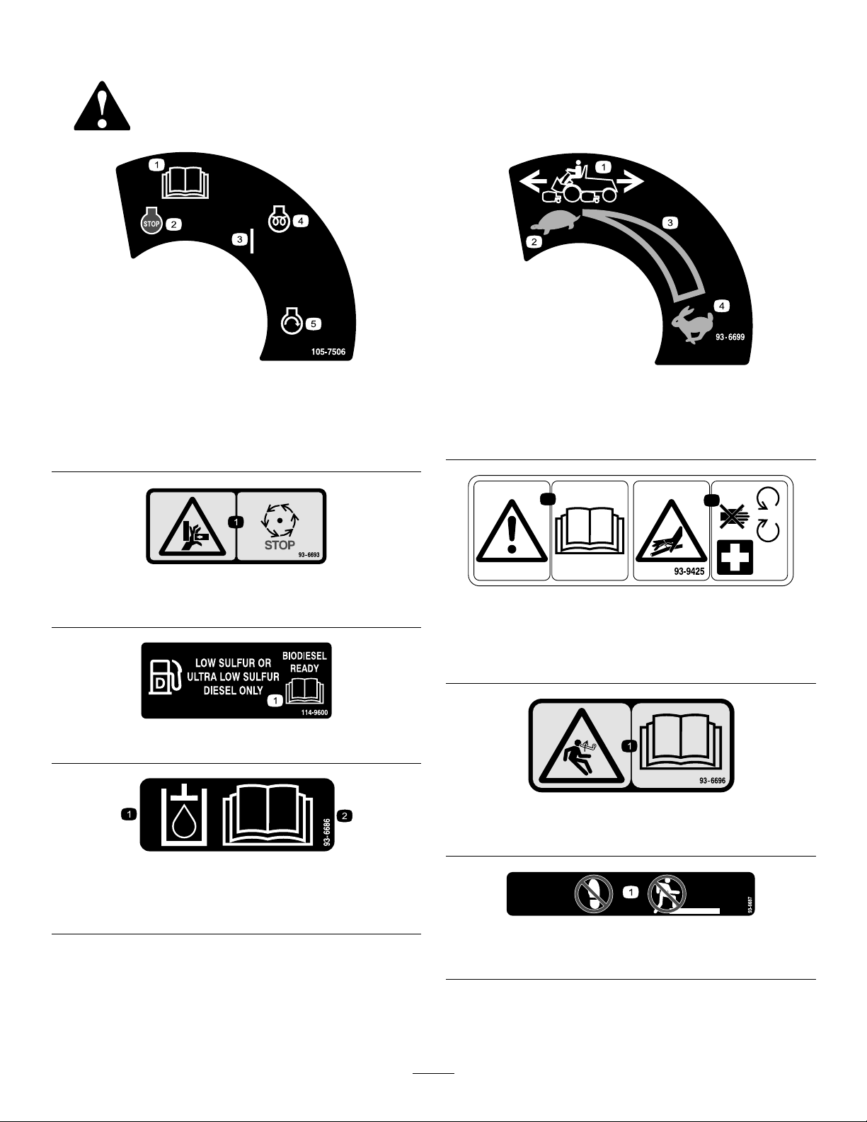
105-7506
1.ReadtheOperator's
Manual.
2.Engine—stop5.Engine—start
3.On
4.Engine—preheat
93-6693
1.Crushinghazardofhand—waitformovingpartstostop.
114–9600
93-6699
1.Machinespeed
2.Slow
3.Continuousvariable
setting
4.Fast
93-9425
1.ReadtheOperator'sManual.
2.Hydraulichosesareunderpressure—stayawayfrom
movingparts.
1.Hydraulicoil
2.ReadtheOperator'sManual.
93-6696
1.Storedenergyhazard—readtheOperator'sManual.
93-6686
93-6687
1.Donotstephere.
7
Page 8
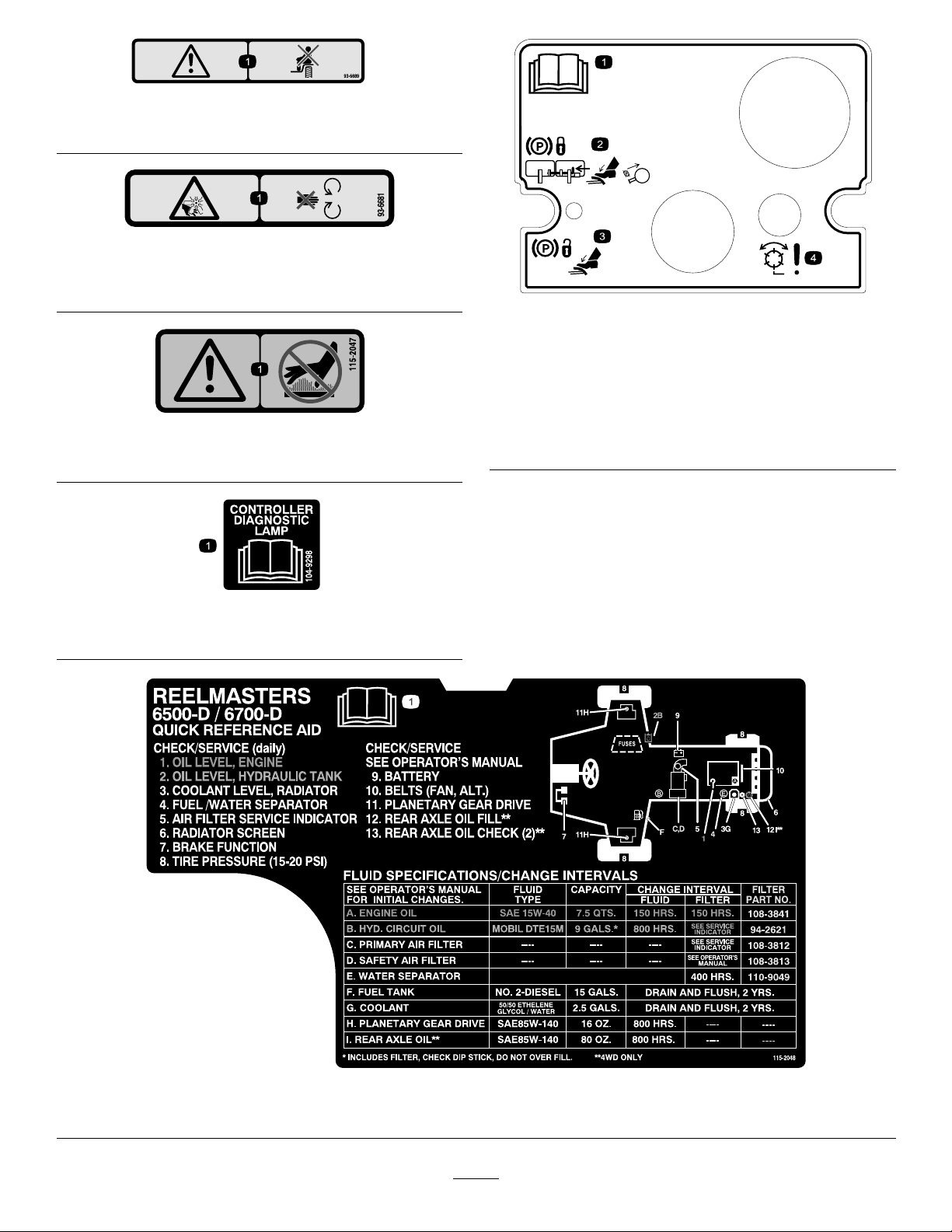
93–6689
93-1263
1.Danger—donotsitontheplasticshroud.
93–6681
1.Cutting/dismembermenthazard—stayawayfrommoving
parts.
115-2047
1.Warning—donottouchthehotsurface.
93-1263
1.ReadtheOperator'sManual.
2.Toengagetheparkingbrake,connectthebrakepedals
withthelockingpin,pushdownonbothpedals,andpullthe
brakelatchout.
3.Toreleasetheparkingbrake,pressbothpedalsuntilthe
parkingbrakelatchretracts.
4.Danger—reelsenabled.
104-9298
1.ReadtheOperator'sManual.
1.ReadtheOperator'sManual.
115-2048
8
Page 9
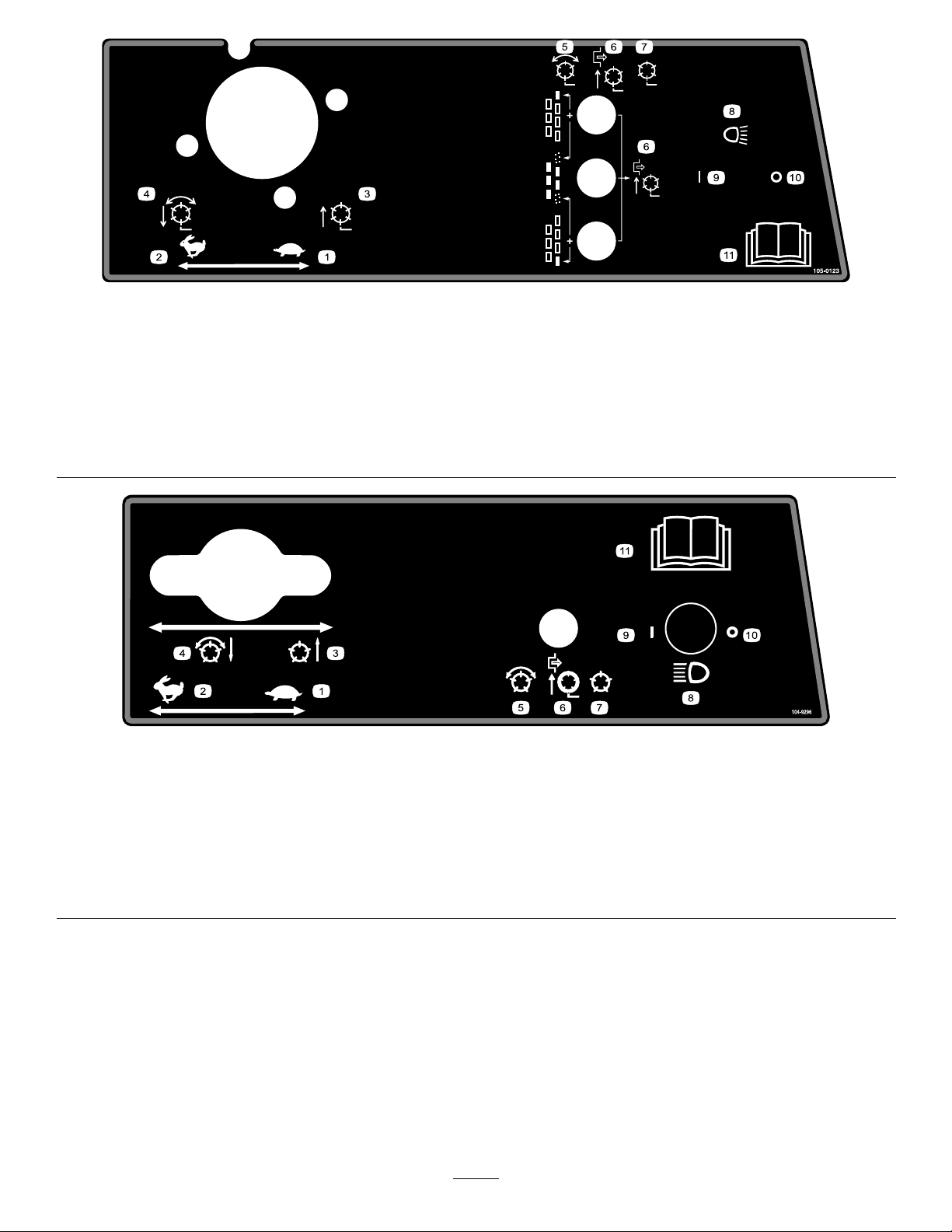
105-0123
Model03808and03813
1.Throttle—slow
2.Throttle—fast8.Headlights(optional)
3.Reelsraisedandoff9.Headlights—On
4.Reelsloweredandonwhenenabled—forwardandbacklap10.Headlights—Off
5.Reels—enabled
6.Reelsdisabled—liftonly
7.Reelsdisabled—liftandlower
11.ReadtheOperatorsManual.
104-9296
Models03806,03807and03812
1.Throttle—slow4.Reelsloweredandonwhen
2.Throttle—fast
3.Reelsraisedandoff6.Reelsdisabled—liftonly9.Headlights—On
enabled—forwardand
backlap
5.Reelsenabled
7.Reelsdisabled—liftand
lower
8.Headlights(optional)11.ReadtheOperator's
10.Headlights—Off
Manualforfurther
instructions.
9
Page 10
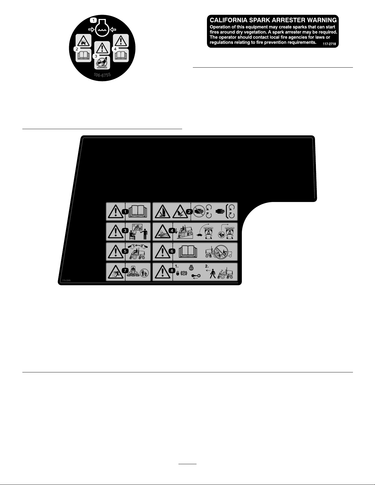
117–2718
106-6755
1.Enginecoolantunder
pressure.
2.Explosionhazard—read
theOperator'sManual.
3.Warning—donottouchthe
hotsurface.
4.Warning—readthe
Operator'sManual.
115-2045
1.Warning—readtheOperator'sManual.
2.Cuttinghazardofhandorfoot—stayawayfrommovingparts;keepallguardsinplace.
3.Warning—donotoperatethismachineunlessyouaretrained.
4.Tippinghazard—lowerthecuttingunitwhendrivingdownslopes;slowmachinebeforeturning,donotturnathighspeeds.
5.Warning—weartheseatbeltwhenseatedintheoperator'sposition.
6.Warning—readtheOperator'sManual;donottowthemachine.
7.Thrownobjecthazard—keepbystandersasafedistancefromthemachine.
8.Warning—locktheparkingbrake,stoptheengineandremovetheignitionkeybeforeleavingthemachine.
10
Page 11
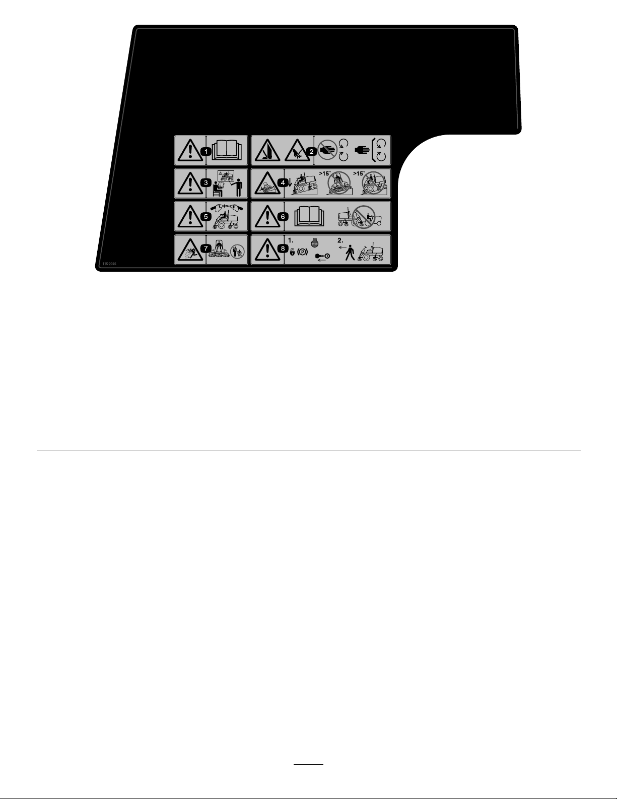
115-2046
(Afxoverpartno.115–2045forCE*)
*ThissafetydecalincludesaslopewarningrequiredonthemachineforcompliancetotheEuropeanLawnMowerSafetyStandardEN836:1997.Theconservativemaximum
slopeanglesindicatedforoperationofthismachineareprescribedbyandrequiredbythisstandard.
1.Warning—readtheOperator'sManual.
2.Cuttinghazardofhandorfoot—stayawayfrommovingparts;keepallguardsinplace.
3.Warning—donotoperatethismachineunlessyouaretrained.
4.Tippinghazard—lowerthecuttingunitwhendrivingdownslopes;donotmowonslopesgreaterthan15degrees.
5.Warning—weartheseatbeltwhenseatedintheoperator'sposition.
6.Warning—readtheOperator'sManual;donottowthemachine.
7.Thrownobjecthazard—keepbystandersasafedistancefromthemachine.
8.Warning—locktheparkingbrake,stoptheengineandremovetheignitionkeybeforeleavingthemachine.
11
Page 12
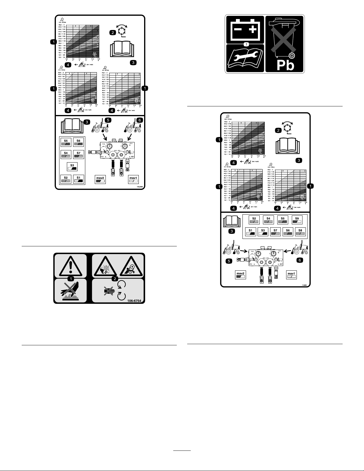
115-2049
Models03806,03807and03812
93-6668
1.ReadtheOperator'sManualforinformationonchargingthe
battery;containslead;donotdiscard.
1.Reel—heightofcut
2.Reel—mowandbacklap5.Rearreelscircuitcontrols
3.ReadtheOperator's
Manual.
4.Machinespeed
6.Frontreelscircuitcontrols
106-6754
1.Warning—donottouchthehotsurface.
2.Cutting/dismembermenthazard,fanandentanglement
hazard,belt—stayawayfrommovingparts.
115-8000
Model03808and03813
1.Reel—heightofcut
2.Reel—mowandbacklap5.Rearreelscircuitcontrols
3.ReadtheOperator's
Manual.
4.Machinespeed
6.Frontreelscircuitcontrols
12
Page 13

BatterySymbols
Someorallofthesesymbolsareonyourbattery
1.Explosionhazard
2.Nore,opename,or
smoking.
3.Causticliquid/chemical
burnhazard
4.Weareyeprotection9.Flusheyesimmediately
5.ReadtheOperator's
Manual.
6.Keepbystandersasafe
7.Weareyeprotection;
8.Batteryacidcancause
10.Containslead;donot
distancefromthebattery .
explosivegasescan
causeblindnessandother
injuries
blindnessorsevereburns.
withwaterandgetmedical
helpfast.
discard.
13
Page 14

Setup
LooseParts
Usethechartbelowtoverifythatallpartshavebeenshipped.
ProcedureDescription
1
2
3
4
5
6
7
Nopartsrequired
LargeO-ring14/10
Counterweight7/5
Steeringlockingpin7/5
Liftchain5/7
Chainbracket5/7
U-bolt
Nut
Screw5/7
Washer
Nut
LargeO-ring5/7
Nopartsrequired
Calciumchloride(obtainseparately)
Rearweightkit,partnumber104–1478
(obtainseparately)
CEdecals
CEcerticate
Operator'sManual
EngineOperator'sManual
PartsCatalog
OperatorTrainingMaterial
DiagnosticACEdisplayoverlay
Ignitionkeysonring1
Hoodlockkey1
Screw
Wingnut2
10/14
100lb
Qty.
5/7
5/7
5/7
Use
–
–
1
4
2
1
1
1
1
1
2
Checkuidlevels.
Installcuttingunits.
Installcuttingunits.
Makecuttingunitadjustmentsifneeded.
Addrearballast(ifrequired).
InstalltheCEdecals.
Readthemanualsandviewthetraining
materialbeforeoperatingthemachine.
1
CheckingFluidLevels
NoPartsRequired
Procedure
Beforestartingtheengineforthersttime,checkthe
followinguidlevels:
•Engineoil
RefertoCheckingtheEngineOil.
•Enginecoolant
RefertoCheckingtheCoolingSystem.
•Hydraulicoil
RefertoCheckingtheHydraulicOil.
•Rearaxlelubricant
RefertoCheckingtheRearAxleLubricant.
14
Page 15
2
InstallingCuttingUnits
Models03860,03861and
03862
Partsneededforthisprocedure:
14/10LargeO-ring
7/5Counterweight
7/5Steeringlockingpin
MounttheCuttingUnits
Cuttingunitmodels03860,03861,and03862canbe
installedatanyofthemountinglocationsonthetraction
unit.Figure3showstheorientationofthehydraulic
drivemotorforeachofthelocations.Foranyofthe
locationsrequiringthemotortobemountedontheright
endofthecuttingunit,installacounterweightonthe
leftendofthecuttingunit.Forthelocationsrequiring
themotortobemountedontheleftend,installa
counterweightontherightendofthecuttingunit.
Note:Counterweightmountingcapscrewsareshipped
installedontherightbearinghousingofthecutting
units.Thecapscrewsonleftbearinghousingaretobe
usedforsecuringthehydraulicmotor.
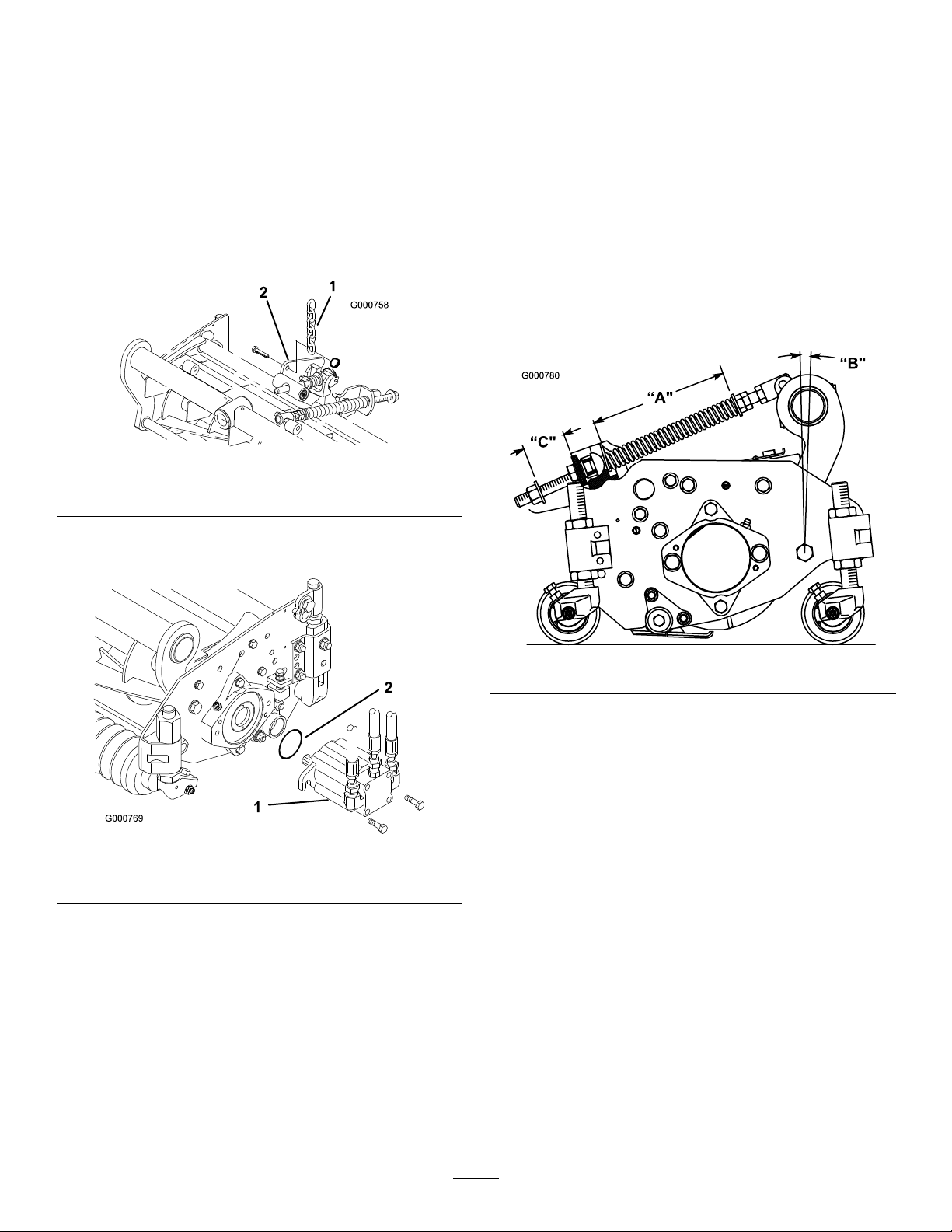
Figure4
1.Bearinghousing
2.Largeo-ring
Note:Beforeinstallingcuttingunitmotorsor
counterweights,lubricateinternalsplinesofcutting
unitreelshaftswithgrease.
4.Installacounterweightontoappropriateendofeach
cuttingunitwithcapscrewsprovided(
5.Thoroughlygreasethecuttingunitreelbearingsprior
toinstallationonthetractionunit.Greaseshould
beevidentattheinboardreelseals;refertoCutting
UnitOperator'sManualforgreasingprocedure.
6.Insertathrustwasherontohorizontalshaftofpivot
knuckleasshownin(
3.Counterweight
Figure4).
Figure5).
Figure3
1.Removecuttingunitsfromcartons.Assembleand
adjustperCuttingUnitOperator'sManual.
2.Removeprotectiveplugsfromeachendofcutting
unit.
3.LubricateandinstallalargeO-ringintobearing
housinggrooveoneachendofcuttingunit
Figure4&Figure7).
(
Figure5
1.Carrierframe
2.Pivotknuckle
3.Liftarmsteeringplate
7.Insertthehorizontalshaftofthepivotknuckleinto
themountingtubeofthecarrierframe(Figure5).
8.Securepivotknuckletocarrierframewithathrust
washer,atwasherandaangeheadcapscrew
(Figure5).
9.Insertathrustwasherontoverticalshaftofpivot
knuckle(Figure5).
15
4.Lynchpin
5.Steeringlockingpin
Page 16
10.Ifremoved,inserttheverticalshaftofthepivot
knuckleintoliftarmpivothub(Figure5).Guide
thepivotknuckleinplacebetweenthetworubber
centeringbumpersintheundersideoftheliftarm
steeringplate.
11.Insertthelynchpinintothecrossholeonthepivot
knuckleshaft(
Figure5).
12.Removenutsecuringturfcompensationspring
mountingbrackettocuttingunitstabilizerear
(Figure6).Inserttipperchainontocapscrewand
securewithnutremoved.
Figure6
1.Liftchain2.Cuttingunitstabilizerear
TheTurfCompensationSpring(Figure8),connecting
carrierframetocuttingunit,controlstheamountof
fore-aftrotationavailable,aswellastheamountof
groundclearanceintransportandturnaround.
TheTurfCompensationSpringalsotransfersweight
fromthefronttorearroller.Thishelpstoreduceawave
patternintheturf,alsoknownasbobbing.
Important:Makespringadjustmentswithcutting
unitmountedtotractionunitandloweredtoshop
oor.
1.Tightenlocknutonrearofspringroduntilthegap
(C)betweenrearofspringbracketandfrontof
washeris1in.(25mm)(
Figure8).
13.Mountthemotortothedriveendofthecuttingunit
andsecurewithtwocapscrewsprovided(
Figure7
1.Motor
2.O-ring
Figure7).
Note:Ifxedcuttingunitpositionisrequired,
insertsteeringlockingpinintopivotknuckle
mountinghole(Figure5).
14.Hookspringwirearoundbottomofsteeringlocking
pin(Figure5).
AdjustTurfCompensationSpring
Figure8
2.Tightenhexnutsonfrontendofspringroduntilthe
compressedlength(A)ofspringis8in.(203mm)
Figure8).
(
Note:Whencuttingroughorundulatingturf,
increasecompressedlength(A)ofspringto8-1/2in.
(216mm)andgap(C)betweenrearofspringbracket
andfrontofwasherto1-1/2in.(38mm)(
Figure8).
Note:Ascompressedspringlength(A)decreases,
weighttransferfromfrontrollertorearroller
increasesandcarrierframe/cuttingunitrotation
angle(B)decreases.
Note:Asgap(C)betweenspringbracketand
washerincreases,cuttingunitgroundclearance
decreasesandcarrierframe/cuttingunitrotation
angle(B)increases.
Tractorsaresetupatthefactoryappropriatelyformost
fairwaymowingapplications.Thefollowingadjustment
isforne-tuningthemachinetotheapplication:
16
Page 17
3
InstallingCuttingUnits
Models03863and03864
Partsneededforthisprocedure:
5/7Liftchain
5/7Chainbracket
U-bolt
5/7
5/7Screw
5/7
5/7
5/7LargeO-ring
Nut
Washer
Nut
10/14
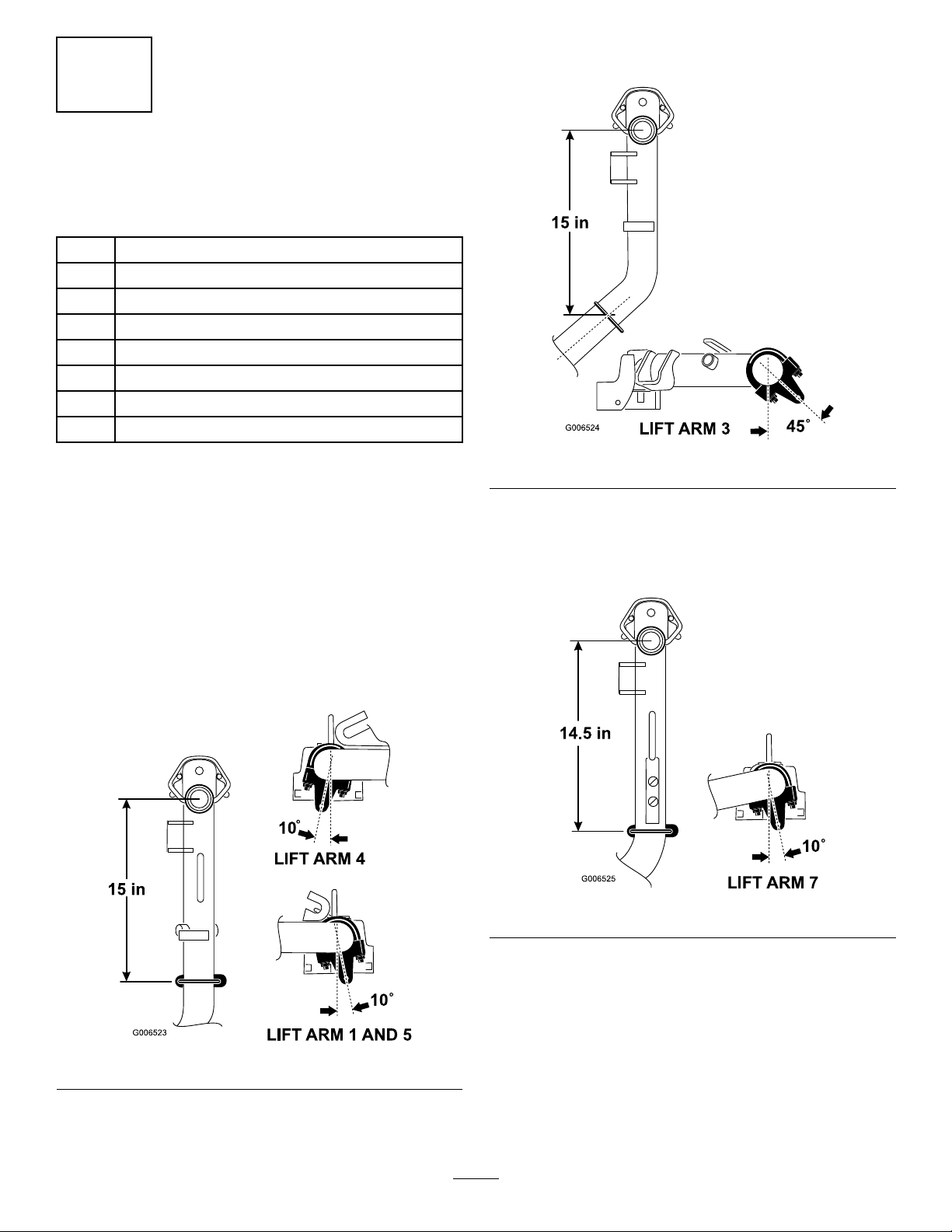
MounttheLiftBracketsandChains
knuckle(Figure10).Rotatethebrackets45degrees
totheoutboardsideofthemachine.
Figure10
MountachainbrackettoeachliftarmwithaU-boltand
2nuts.Positionthebracketsasfollows:
1.Onliftarms#1,#4and#5,positionthechain
bracketsandU-bolts15inchesbehindthecenter
lineofthepivotknuckle(
and#5thebracketsshouldberotatedtotheright
10degreesfromvertical(Figure9).Onliftarm#4
thebracketshouldberotatedtotheleft10degrees
fromvertical(Figure9).
Figure9).Onliftarms#1
3.Onliftarms#6and#7,positionthebracketsand
U-bolts14.5inchesbehindthecenterlineofthe
pivotknuckle(
degreestotheoutboardsideofthemachine.
4.TightenalltheU-boltnutsto38–48ft-lbs.
Figure11).Rotatethebrackets10
Figure11
Figure9
2.Onliftarms#2and#3,positionthebracketsand
U-bolts15inchesbehindthecenterlineofthepivot
5.Mountaliftchaintoeachchainbracketwithascrew ,
washerandnut,positioningasshowninFigure12
17
Page 18
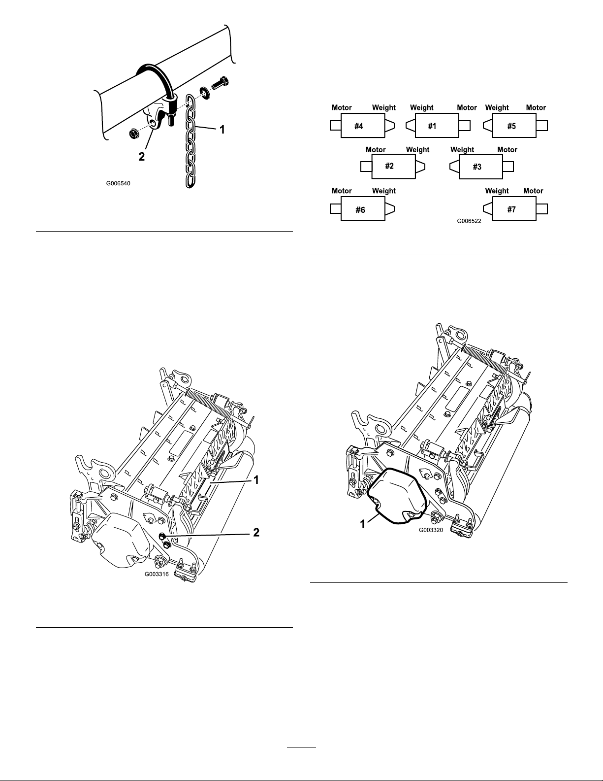
Figure12
1.Liftchain2.Chainbracket
AdjusttheRearShield
Undermostconditions,bestdispersionisattained
whentherearshieldisclosed(frontdischarge).When
conditionsareheavyorwet,rearshieldmaybeopened.
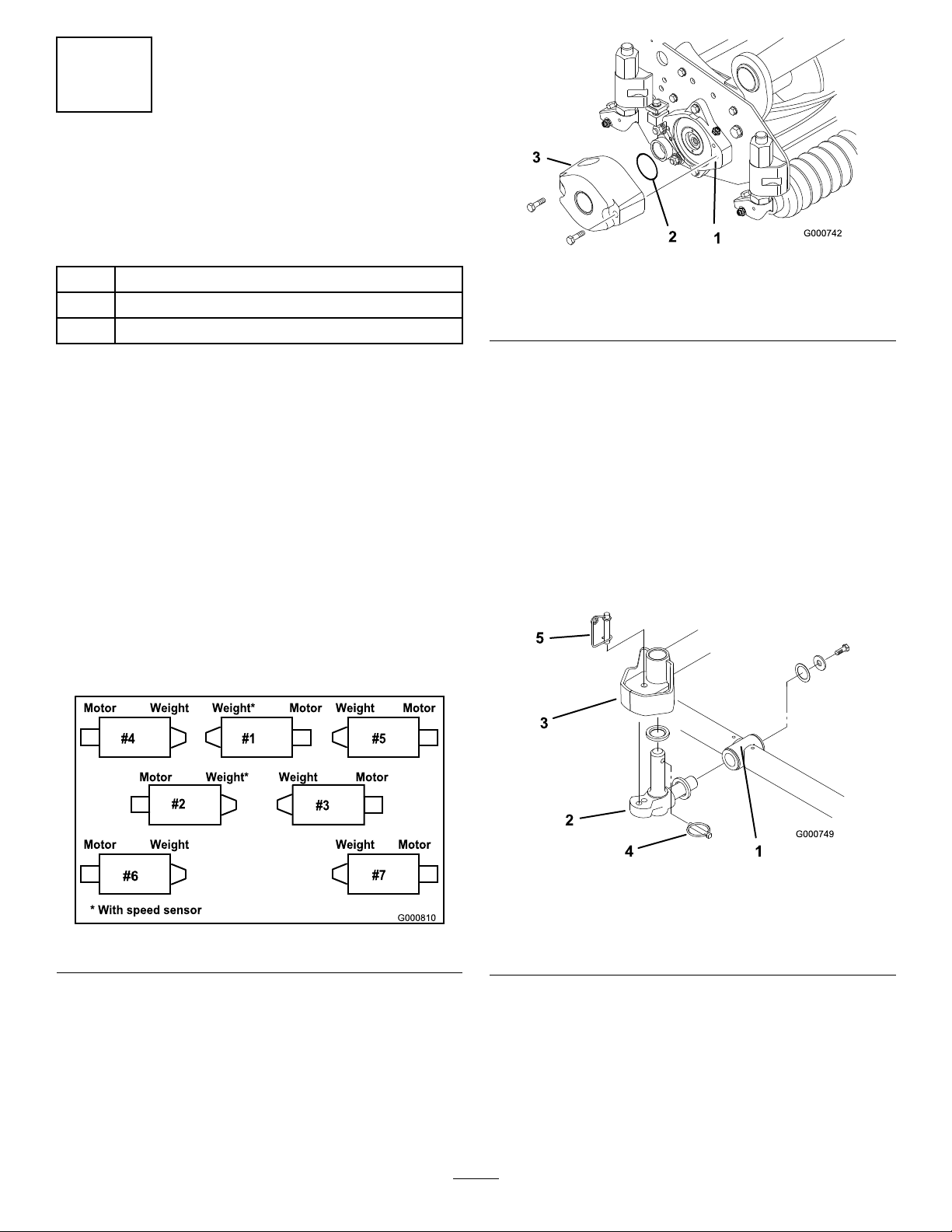
MounttheCounterWeights
Allcuttingunitsareshippedwiththecounterweight
mountedtotheleftendofthecuttingunit.Usethe
followingdiagramtodeterminethepositionofthe
counterweightsandreelmotors.
Figure14
1.Onthe#2,#4and#6cuttingunits,removethe2
capscrewssecuringthecounterweighttotheleft
endofthecuttingunit.Removethecounterweight
Figure15).
(
Toopentherearshield(
Figure13),loosenthecapscrew
securingtheshieldtotheleftsideplate,rotatetheshield
totheopenpositionandtightenthecapscrew .
Figure13
1.Rearshield
2.Capscrew
Figure15
1.Counterweight
2.Onrightendofcuttingunit,removetheplasticplug
fromthebearinghousing(Figure16).
3.Removethe2capscrewsfromtherightsideplate
(Figure16).
18
Page 19
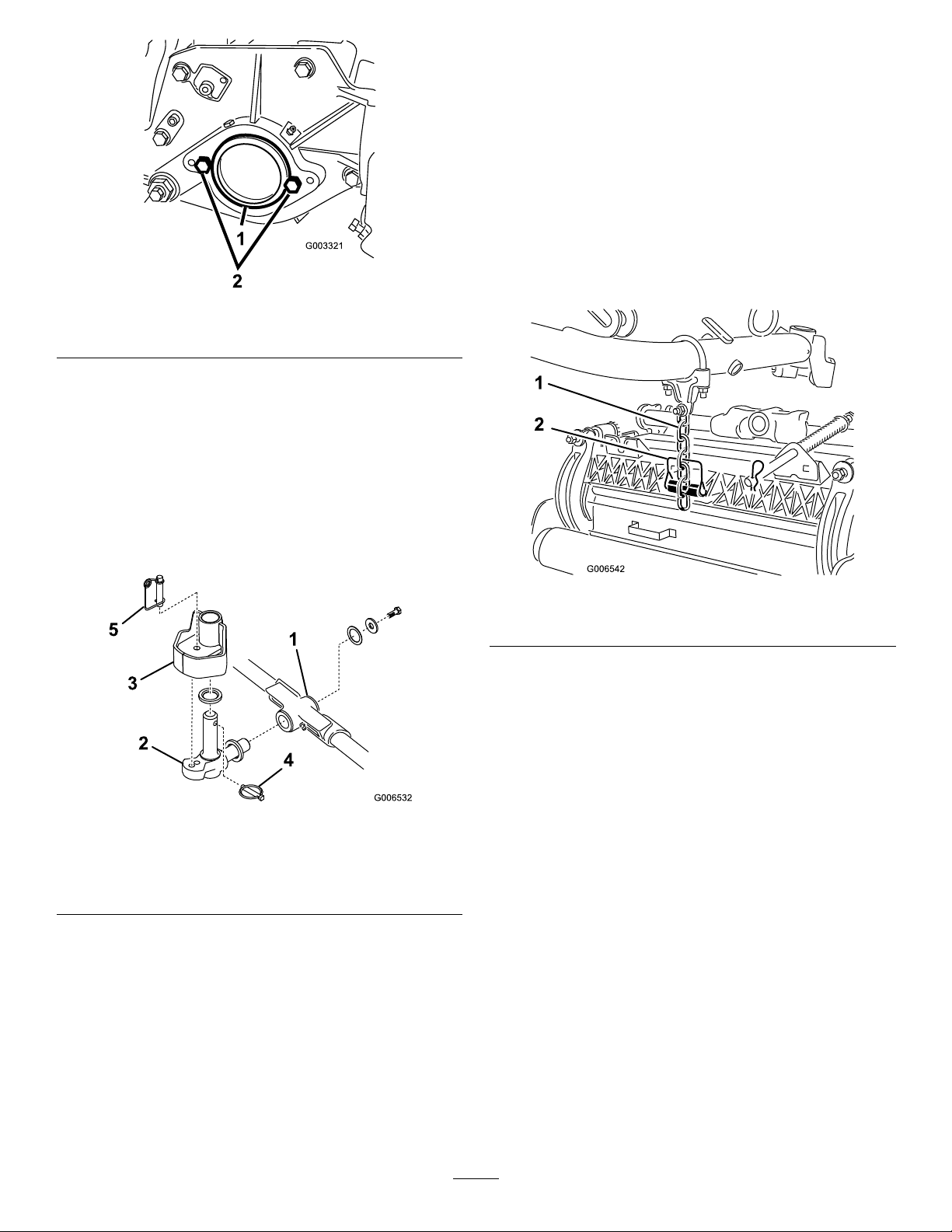
G003321
1
2
Figure16
thepivotknuckleinplacebetweenthetworubber
centeringbumpersintheundersideoftheliftarm
steeringplate.
6.Insertthelynchpinintothecrossholeonthepivot
knuckleshaft(Figure17).
7.Securetheliftarmchaintothecuttingunitchain
bracket(
Figure18)withthesnapperpinasfollows:
A.Oncuttingunits#1,4,5,6and7,onlyuse6of
thechainlinks.
B.Oncuttingunits#2and3,useall7ofthechain
links.
1.Plasticplug
2.Capscrew(2)
4.Installthecounterweighttotherightendofthe
cuttingunitwiththe2screwspreviouslyremoved.
5.Looselyinstallthe2reelmotormountingcapscrews
totheleftsideplateofthecuttingunit(Figure16).
MounttheCuttingUnits
1.Insertathrustwasherontohorizontalshaftofpivot
knuckleasshowninFigure17.
Figure17
Figure18
1.Liftchain2.Snapperpin
8.Coatthesplineofthereelmotorwithcleangrease.
9.OilthereelmotorO-ringandinstallitontothe
motorange.
10.Installthemotorbyrotatingitclockwisesothat
themotorangesclearthecapscrews(
Figure19).
Rotatethemotorcounterclockwiseuntiltheanges
encirclethecapscrewsthentightenthecapscrews
1.Carrierframe
2.Pivotknuckle
3.Liftarmsteeringplate
4.Lynchpin
5.Steeringlockingpin
2.Insertthehorizontalshaftofthepivotknuckleinto
themountingtubeofthecarrierframe(Figure17).
3.Securepivotknuckletocarrierframewithathrust
washer,atwasherandaangeheadcapscrew
(Figure17).
4.Insertathrustwasherontoverticalshaftofpivot
knuckle(
Figure17).
5.Ifremoved,inserttheverticalshaftofthepivot
knuckleintoliftarmpivothub(
Figure17).Guide
Important:Makesurethereelmotorhoses
arenottwisted,kinkedorintheriskofbeing
pinched.
19
Page 20
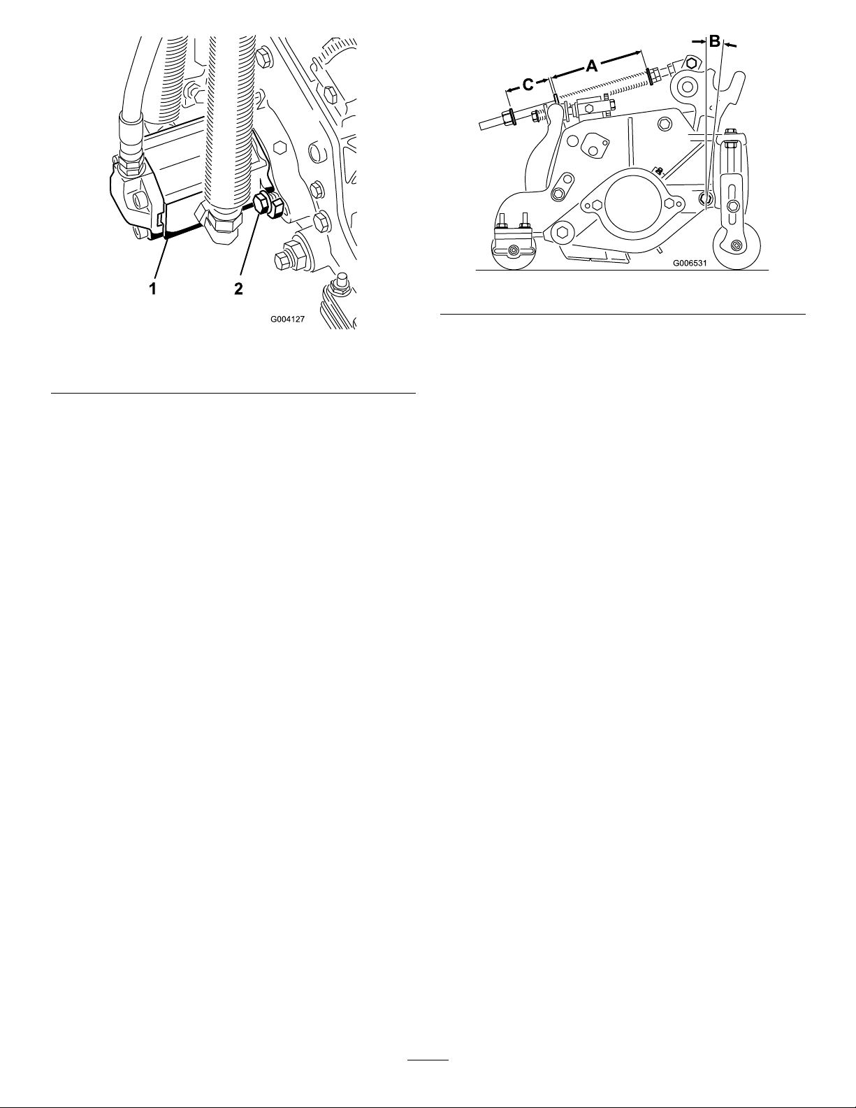
Figure20
Figure19
1.Reeldrivemotor
2.Capscrew
Note:Ifxedcuttingunitpositionisrequired,
insertsteeringlockingpinintopivotknuckle
mountinghole(
Figure17).
11.Hookspringwirearoundbottomofsteeringlocking
pin(Figure17).
AdjusttheTurfCompensationSpring
Tractorsaresetupatthefactoryappropriatelyformost
fairwaymowingapplications.
Thefollowingadjustmentsareavailableforne-tuning
ofthemachinetotheapplication:
TheTurfCompensationSpring(Figure20)transfers
weightfromthefronttorearroller.Thishelpstoreduce
awavepatternintheturf,alsoknownasbobbing.
Important:Makespringadjustmentswithcutting
unitmountedtotractionunitandloweredtoshop
oor.
2.Tightenhexnutsonfrontendofspringroduntil
thecompressedlength(A)ofspringis6.25in.(159
mm)(Figure20).
Note:Whenoperatingonroughterrain,decrease
thespringlengthby1/2inch.Groundfollowingwill
beslightlydecreased.
Note:Ascompressedspringlength(A)decreases,
weighttransferfromfrontrollertorearroller
increasesandcarrierframe/cuttingunitrotation
angle(B)decreases.
Note:Asgap(C)betweenspringbracketand
washerincreases,cuttingunitgroundclearance
decreasesandcarrierframe/cuttingunitrotation
angle(B)increases.
Note:Whencuttingundulatingturf,increasethe
compressedspringlength(A)andthegapwidth(C)
1/2inch(
Figure20).
1.Tightenlocknutonrearofspringroduntilthegap
(C)betweenrearofspringbracketandfrontof
washeris2in.(51mm)(
Figure20).
20
Page 21

4
6
MakingAlternateCuttingUnit
Adjustments
NoPartsRequired
Procedure
Thefactorysetsthetractorappropriatelyformost
fairwaymowingapplications.Severaladjustmentsfor
ne-tuningthemachineforparticularapplicationsare
includedintheCuttingUnitMaintenancesectionas
follows:
•Adjustingthecuttingunitloweringrate
Adjuststhespeedatwhichthecuttingunitslower.
•Adjustingtheliftedheightoftheouterfrontcutting
units
Adjuststheturnaroundheightoftheouterfront
cuttingunitstoprovidegreaterclearanceon
contouredfairways.
•Adjustingthetravelofthefrontthreecuttingunits
InstallingCEDecals
Partsneededforthisprocedure:
4
CEdecals
2
CEcerticate
Procedure
IfyouwillbeusingthemachineinaCEcountry,install
thesuppliedCEdecalsoverthecorrespondingANSI
decalsontheproduct.StoretheCEcerticatesinasafe
location.
7
ReadingtheManualsand
StoringAdditionalParts
Adjuststhedownwardtravelofthefrontthree
cuttingunitstoallowforhighlycontouredfairways.
5
AddingRearBallast
Partsneededforthisprocedure:
100lb
Procedure
TocomplywithCENstandardEN836:1997,ISO
standard5395:1990,andtheANSIB71.4-2004
Standard,add100lb(45kg)ofcalciumchloride
ballasttotherearwheelsandinstalltherearweightkit
(PartNumber104-1478).
Calciumchloride(obtainseparately)
Rearweightkit,partnumber104–1478(obtain
1
separately)
Partsneededforthisprocedure:
1
Operator'sManual
1
EngineOperator'sManual
1
PartsCatalog
1
OperatorTrainingMaterial
1
DiagnosticACEdisplayoverlay
1Ignitionkeysonring
1Hoodlockkey
2
Screw
2Wingnut
Procedure
1.Readthemanuals.
2.ViewtheOperatorTrainingMaterial.
3.ThediagnosticACEdisplayoverlayisfordiagnosing
machinemalfunctions.Storeitinasafelocation.
Important:Ifapunctureoccursinatirewith
calciumchloride,removeunitfromturfareaas
quicklyaspossible.Topreventpossibledamageto
turf,immediatelysoakaffectedareawithwater.
21
Page 22

ProductOverview
g019447
1
2
3
4
5
6
7
8
9
Controls
TractionPedal
Thetractionpedal(Figure21)controlsforwardand
reverseoperation.Depresstopofpedaltomoveforward
andbottomtomovebackward.Groundspeeddepends
onhowfarpedalisdepressed.Fornoload,maximum
groundspeed,fullydepresspedalwhilethrottleisin
FAST.
Tostop,reducefootpressureontractionpedaland
allowittoreturntocenterposition.
•Themachineisbeingoperatedfasterthanthe
maximumspeedvalueinitiallyprogrammedintothe
ECU.
•Anelectricalmalfunctionhasbeendetected(open
orshortedoutput.
•Ahydraulicleakhasbeendetected(Onlyif
Turfdefenderleakdetectorisinstalledonmachine)
•Acommunicationserrorhasbeendetected(Onlyif
Turfdefenderleakdetectorisinstalledonmachine)
KeySwitch
Thekeyswitch(Figure21)hasthreepositions:OFF ,
ON/PreheatandSTART.
Speedometer
Thespeedometer(Figure21)indicatesgroundspeedat
whichmachineistraveling.
BrakePedals
Twobrakepedals(Figure21)operateindividualwheel
brakesforturningassistance,parking,andtoaidin
obtainingbettersidehilltraction.Lockingpinconnects
thepedalsforparkingbrakeoperationandtransport.
Figure21
1.Tractionpedal6.Parkingbrakelatch
2.Forwardspeedlimiter7.Lockingpin
3.Reddiagnosticlight8.Reversespeedlimiter
4.Speedometer
5.Brakepedals
9.Keyswitch
ForwardSpeedLimiter
Presettheforwardspeedlimiter(Figure21)tolimit
theamountthetractionpedalcanbedepressedinthe
forwarddirectiontomaintainaconstantmowingspeed.
RedDiagnosticLight
Thereddiagnosticlight(Figure21),locatedonsteering
tower,isusedtoconveyseveraldifferentmessages.
Whilestartingthemachine,thelightwillilluminatewhen
theglowplugsareon.
Ifthelightblinksduringoperation,itmayindicateany
ofthefollowing:
ParkingBrakeLatch
Aknobontheleftsideofconsoleactuatesparkingbrake
lock(Figure21).Toengageparkingbrake,connect
pedalswithlockingpin,pushdownonbothpedalsand
pullparkingbrakelatchout.Toreleaseparkingbrake,
depressbothpedalsuntilparkingbrakelatchretracts.
ReverseSpeedLimiter
Adjustthescrew(Figure21)tolimittheamountthe
tractionpedalcanbedepressedintherearwarddirection
tolimitspeed.
LowerMow/RaiseControlLever
(Joystick)
Thelever(Figure22andFigure23)raisesandlowersthe
cuttingunitsandalsostartsandstopsthereels.
FuelGauge
Thefuelgauge(Figure22andFigure23)indicateslevel
offuelintank.
EngineOilPressureWarningLight
Thislight(Figure22andFigure23)indicatesdangerously
lowengineoilpressure.
22
Page 23

G019448
1
2
3
4
5
6
7
8
9
10
11
Figure22
G019449
1
2
3
4
5
6
7
8
9
Model03808and03813
1.Throttlecontrol
2.Lowermow/raisecontrol
lever
3.Fuelgauge
4.Chargeindicator10.Enable/disableswitch
5.Engineoilpressure
warninglight
6.Enginecoolant
temperaturewarning
light
7.Glowplugindicatorlight
8.Enginecoolant
temperaturegauge
9.Enable/disableswitch(#7)
rightrear
(Master)
11.Enable/disableswitch(#6)
leftrear
ThrottleControl
Movethecontrol(Figure22andFigure23)forwardto
increaseenginespeed,rearwardtodecreasespeed.
EngineCoolantTemperatureWarning
Light
Thelight(Figure22andFigure23)illuminatesand
theengineshutsdownwhenthecoolantreachesa
dangerouslyhightemperature.
GlowPlugIndicatorLight
Figure23
Models03806,03807and03812
1.Throttlecontrol6.Enginecoolant
2.Lowermow/raisecontrol
lever
3.Fuelgauge8.Enginecoolant
4.Chargeindicator9.Enable/disableswitch
5.Engineoilpressure
warninglight
temperaturewarning
light
7.Glowplugindicatorlight
temperaturegauge
(Master)
Enable/DisableSwitches
Theenable/disableswitches(Figure22andFigure23)
areusedinconjunctionwiththelowermow/raise
controllever(Joystick)tooperatereels.Reelscanbe
raisedbutnotloweredwheninmidposition.
HourMeter
Thehourmeter(Figure24)showstotalhoursthat
machinehasbeenoperated.
Whentheindicatorlight(Figure22andFigure23)islit,
indicatesglowplugsareon.
ChargeIndicator
Thechargeindicator(Figure22andFigure23)
illuminateswhensystemchargingcircuitmalfunctions.
23
Page 24

G019525
1
1.Hourmeter
G019451
1
2
adjustsseatforoperatorsweight.Toadjustseatfore
andaft,pullleveronleftsideofseatassemblyoutward.
Aftermovingseattodesiredlocation,releaseleverto
lockseatintoposition.Toadjustforoperatorsweight,
turnspringtensionknob;clockwisetoincreasetension,
counterclockwisetodecreasespringtension.
Figure24
BacklapKnobs
Thebacklapknobs(Figure25)areusedin
conjunctionwithlowermow/raisecontrollever
forbacklappingoperation.RefertoBacklappingin
CuttingUnitMaintenance(page53).
Figure25
Figure26
1.Seatadjustingknob2.Seatadjustinglever
GreenDiagnosticLight
Themachineisequippedwithadiagnosticlightwhich
indicatesiftheelectroniccontrollerisfunctioning
correctly.Thegreendiagnosticlight(Figure27)is
locatedunderthecontrolpanel,nexttothefuseblock.
Whentheelectroniccontrollerisfunctioningcorrectly
andthekeyswitchismovedtotheONposition,the
controllerdiagnosticlightwillbeilluminated.Thelight
willblinkifthecontrollerdetectsamalfunctionin
theelectricalsystem.Thelightwillstopblinkingand
automaticallyresetwhenthekeyswitchisturnedtothe
OFFposition.
1.Backlapknobs2.Reelcontrolknobs
ReelSpeedControls
ControlsRPMoffrontandrearcuttingunits(Figure25).
#1positionisforbacklapping.Remainingsettingsare
formowingoperations.Seedecalunderseatforproper
settings.
Seat
Theseatadjustinglever(Figure26)allows4inchfore
andaftadjustment.Theseatadjustingknob(Figure26)
24
Page 25

G019452
1
TheDiagnosticACEdisplayisatooltohelptheuser
verifycorrectelectricalfunctionsofthemachine.
Specications
Note:Specicationsanddesignaresubjecttochange
withoutnotice.
Figure27
1.Greendiagnosticlight
Whenthecontrollerdiagnosticlightblinks,oneofthe
followingproblemshasbeendetectedbythecontroller:
•Oneoftheoutputshasbeenshorted.
•Oneoftheoutputsisopencircuited.
Usingthediagnosticdisplay,determinewhichoutput
ismalfunctioning,refertoCheckingInterlock
Switches.
Ifthediagnosticlightisnotilluminatedwhenthe
keyswitchisintheOnposition,thisindicatesthat
theelectroniccontrollerisnotoperating.Possible
causesare:
•Loopbackisnotconnected.
•Thelightisburnedout.
Width-of-cut,model03806,
03807and03812
Width-of-cut,model03808and
03813
Overallwidth,Transport89inches(226cm)
Overallwidth,Operational110inches(279cm)
Overalllength120inches(305cm)
HeightWithROPSinstalled84inches(213cm)
Weight*,model038063200lb(1451kg)
Weight*,model03807and
03812
Weight*,model03808and
03813
*With5bladecuttingunitsandfulluidlevels.
96inches(244cm)
133inches(338cm)
3300lb(1496kg)
3950lb(1792kg)
Attachments/Accessories
AselectionofToroapprovedattachmentsand
accessoriesisavailableforusewiththemachineto
enhanceandexpanditscapabilities.Contactyour
AuthorizedServiceDealerorDistributororgoto
www.Toro.comforalistofallapprovedattachments
andaccessories.
•Fusesareblown.
•Nobatterypower.
Checkelectricalconnections,inputfusesand
diagnosticlightbulbtodeterminemalfunction.
Makesureloopbackconnectorissecuredtowire
harnessconnector.
DiagnosticACEDisplay(Optional)
Themachineisequippedwithanelectroniccontroller
whichcontrolsmostmachinefunctions.Thecontroller
determineswhatfunctionisrequiredforvariousinput
switches(i.e.seatswitch,keyswitch,etc.)andturns
ontheoutputstoactuatesolenoidsorrelaysforthe
requestedmachinefunction.
Fortheelectroniccontrollertocontrolthemachineas
desired,eachoftheinputswitches,outputsolenoidsand
relaysmustbeconnectedandfunctioningproperly .
25
Page 26

Operation
g019453
1
G019454
1
G019455
1
Note:Determinetheleftandrightsidesofthe
machinefromthenormaloperatingposition.
CheckingtheEngineOil
ServiceInterval:Beforeeachuseordaily
Theengineisshippedwithoilinthecrankcase;
however,theoillevelmustbecheckedbeforeandafter
theengineisrststarted.
Crankcasecapacityisapproximately7.5qt.(7l)with
thelter.
Usehigh-qualityengineoilthatmeetsthefollowing
specications:
Figure29
1.Dipstick
•APIClassicationLevelRequired:CH-4,CI-4or
higher.
•Preferredoil:SAE15W -40(above0°F)
•Alternateoil:SAE10W -30or5W-30(all
temperatures)
Note:ToroPremiumEngineoilisavailablefromyour
distributorineither15W-40or10W-30viscosity.See
thepartscatalogforpartnumbers.
Note:Thebesttimetochecktheengineoiliswhen
theengineiscoolbeforeithasbeenstartedforthe
day.Ifithasalreadybeenrun,allowtheoiltodrain
backdowntothesumpforatleast10minutesbefore
checking.Iftheoillevelisatorbelowthe“add”mark
onthedipstick,addoiltobringtheoilleveltothe“full”
mark.DONOTOVERFILL.Iftheoillevelisbetween
the“full”and“add”marks,nooiladditionisrequired.
1.Parkmachineonalevelsurface.Releasehoodlatch
andopenhood(
Figure28).
3.Ifoillevelislow,removellercap(Figure30)and
addoiluntillevelreachesFULLmarkondipstick.
Donotoverll.
Figure30
1.Fillercap
4.Installllercap.
5.Closehoodandsecurelatch.
Figure28
1.Hoodlatch
2.Removedipstick(Figure29),wipecleanandreinstall
dipstick.Pullitoutagainandcheckoillevelon
dipstick:OillevelshouldbeuptoFULLmarkon
dipstick.
CheckingtheCoolingSystem
ServiceInterval:Beforeeachuseordaily
Cleandebrisoffscreen,oilcoolerandfrontof
radiatordaily,moreoftenifconditionsareextremely
dustyanddirty;refertoRemovingDebrisin
CoolingSystemMaintenance(page49).
Thecoolingsystemislledwitha50/50solution
ofwaterandpermanentethyleneglycolantifreeze.
Checklevelofcoolantinradiatorandexpansiontank
26
Page 27

atthebeginningofeachdaybeforestartingtheengine.
1
G019456
Capacityofcoolingsystemis10quarts(9.4l).
CAUTION
Iftheenginehasbeenrunning,pressurizedhot
coolantcanescapeandcauseburnsiftheradiator
capisremoved.
Allowtheenginetocoolatleast15minutesoruntil
theradiatorcapiscoolenoughtotouchwithout
burninghands.
1.Carefullyremoveradiatorcapandexpansiontank
cap(Figure31).
2.Checklevelofcoolantinradiatorandinexpansion
Figure31).
tank(
Radiatorshouldbelledtothetopofthellerneck
andtheexpansiontanklledtotheFullmark.
Figure32
1.Ventplug
4.Installradiatorcapandexpansiontankcap.
5.Closehoodandsecurelatch.
FillingtheFuelTank
Figure31
1.Expansiontank
3.FillexpansiontanktotheFullmarkandradiator
tothetopofthellerneck.Donotoverllthe
expansiontank.
Note:Ifairistrappedissystem,removeventplug
Figure32),fromtopofradiatorsidetank,toallow
(
trappedairtoescape.Reinstallventplugusing
Teonthreadsealant.
DANGER
Undercertainconditions,dieselfuelandfuel
vaporsarehighlyammableandexplosive.Are
orexplosionfromfuelcanburnyouandothersand
cancausepropertydamage.
•Useafunnelandllthefueltankoutdoors,in
anopenarea,whentheengineisoffandiscold.
Wipeupanyfuelthatspills.
•Donotllthefueltankcompletelyfull.Add
fueltothefueltankuntilthelevelis1in.(25
mm)belowthebottomofthellerneck.This
emptyspaceinthetankallowsthefuelto
expand.
•Neversmokewhenhandlingfuel,andstay
awayfromanopenameorwherefuelfumes
maybeignitedbyaspark.
•Storefuelinaclean,safety-approvedcontainer
andkeepthecapinplace.
Useonlyclean,freshdieselfuelorbiodieselfuelswith
low(<500ppm)orultralow(<15ppm)sulfurcontent.
Theminimumcetaneratingshouldbe40.Purchase
fuelinquantitiesthatcanbeusedwithin180daysto
ensurefuelfreshness.
Fueltankcapacity:15USgallons(57l)
Usesummergradedieselfuel(No.2-D)attemperatures
above20°F(-7°C)andwintergrade(No.1-Dor
No.1-D/2-Dblend)belowthattemperature.Useof
wintergradefuelatlowertemperaturesprovideslower
27
Page 28

ashpointandcoldowcharacteristicswhichwillease
startingandreducefuellterplugging.
Useofsummergradefuelabove20°F(-7°C)will
contributetowardlongerfuelpumplifeandincreased
powercomparedtowintergradefuel.
Important:Donotusekeroseneorgasoline
insteadofdieselfuel.Failuretoobservethis
cautionwilldamagetheengine.
DANGER
Incertainconditions,fuelisextremelyammable
andhighlyexplosive.Areorexplosionfromfuel
canburnyouandothersandcandamageproperty.
•Fillthefueltankoutdoors,inanopenarea,
whentheengineiscold.Wipeupanyfuelthat
spills.
•Neverllthefueltankinsideanenclosedtrailer.
WARNING
Fuelisharmfulorfatalifswallowed.Long-term
exposuretovaporscancauseseriousinjuryand
illness.
•Avoidprolongedbreathingofvapors.
•Keepfaceawayfromnozzleandgastankor
conditioneropening .
•Keepfuelawayfromeyesandskin.
BiodieselReady
Thismachinecanalsouseabiodieselblendedfuel
ofuptoB20(20%biodiesel,80%petrodiesel).The
petrodieselportionshouldbeloworultralowsulfur.
Observethefollowingprecautions:
•Thebiodieselportionofthefuelmustmeet
specicationASTMD6751orEN14214.
•TheblendedfuelcompositionshouldmeetASTM
D975orEN590.
•Paintedsurfacesmaybedamagedbybiodiesel
blends.
•UseB5(biodieselcontentof5%)orlesserblends
incoldweather.
•Monitorseals,hoses,gasketsincontactwithfuelas
theymaybedegradedovertime.
•Fuellterpluggingmaybeexpectedforatimeafter
convertingtobiodieselblendsd.
•Contactyourdistributorifyouwishformore
informationonbiodiesel.
•Neversmokewhenhandlingfuel,andstay
awayfromanopenameorwherefuelfumes
maybeignitedbyaspark.
•Storefuelinanapprovedcontainerandkeepit
outofthereachofchildren.Neverbuymore
thana30-daysupplyoffuel.
•Donotoperatewithoutentireexhaustsystem
inplaceandinproperworkingcondition.
DANGER
Incertainconditionsduringfueling,static
electricitycanbereleasedcausingasparkwhich
canignitethefuelvapors.Areorexplosionfrom
fuelcanburnyouandothersandcandamage
property.
•Alwaysplacefuelcontainersontheground
awayfromyourvehiclebeforelling.
•Donotllfuelcontainersinsideavehicleoron
atruckortrailerbedbecauseinteriorcarpets
orplastictruckbedlinersmayinsulatethe
containerandslowthelossofanystaticcharge.
•Whenpractical,removeequipmentfromthe
truckortrailerandrefueltheequipmentwith
itswheelsontheground.
•Ifthisisnotpossible,thenrefuelsuch
equipmentonatruckortrailerfromaportable
container,ratherthanfromafueldispenser
nozzle.
•Ifafueldispensernozzlemustbeused,keep
thenozzleincontactwiththerimofthefuel
tankorcontaineropeningatalltimesuntil
fuelingiscomplete.
1.Parkthemachineonalevelsurface.
2.Usingacleanrag,cleanareaaroundfueltankcap.
3.Removecapfromthefueltank(Figure33).
28
Page 29

1
G019457
Note:Manyhydraulicuidsarealmostcolorless,
1
G019458
makingitdifculttospotleaks.Areddyeadditivefor
thehydraulicsystemoilisavailablein2/3oz.(20ml)
bottles.Onebottleissufcientfor4-6gal(15-221)
ofhydraulicoil.Orderpartno.44-2500fromyour
authorizedTorodistributor.
BiodegradableHydraulicFluid-Mobil224H
ToroBiodegradableHydraulicFluid(Availablein5gallon
pailsor55gallondrums.SeepartscatalogorT orodistributor
forpartnumbers.)
Alternateuid:MobilEAL224H
Figure33
1.Fueltankcap
4.Fillthetankuntilthelevelistothebottomofthe
llerneckwithdieselfuel.
5.Installfueltankcaptightlyafterllingtank.
Note:Ifpossible,llthefueltankaftereachuse.
Thiswillminimizepossiblebuildupofcondensation
insidethefueltank.
CheckingtheHydraulicFluid
ServiceInterval:Beforeeachuseordaily
Themachinesreservoirislledatthefactorywith
approximately8.5U.S.gallons(32l)ofhighquality
hydraulicuid.Checkthelevelofthehydraulicuid
beforetheengineisrststartedanddailythereafter.
Therecommendedreplacementuidisasfollows:
ToroPremiumAllSeasonHydraulicFluid(Availablein5
gallonpailsor55gallondrums.SeepartscatalogorT oro
distributorforpartnumbers.)
Note:Thisisvegetable-oilbasedbiodegradableoil
testedandapprovedbyToroforthismodel.Thisuid
isnotasresistanttohightemperaturesasstandard
uid,soinstallanoilcoolerifrequiredbytheoperator
manualandfollowrecommendeduidchangeintervals
withthisuid.Contaminationbymineral-based
hydraulicuidswillchangethebiodegradabilityand
toxicityofthisoil.Whenchangingfromstandarduid
tothebiodegradabletype,becertaintofollowthe
approvedushingprocedure.ContactyourlocalT oro
Distributorfordetails.
1.Positionmachineonalevelsurface,lowerthe
cuttingunitsandstoptheengine.
2.Cleanareaaroundllerneckandcapofhydraulic
Figure34).Removecapfromllerneck.
tank(
Alternateuids:IftheTorouidisnotavailable,other
uidsmaybeusedprovidedtheymeetallthefollowing
materialpropertiesandindustryspecications.Wedo
notrecommendtheuseofsyntheticuid.Consult
withyourlubricantdistributortoidentifyasatisfactory
productNote:Torowillnotassumeresponsibilityfor
damagecausedbyimpropersubstitutions,souseonly
productsfromreputablemanufacturerswhowillstand
behindtheirrecommendation.
HighViscosityIndex/LowPourPointAnti-wearHydraulic
Fluid,ISOVG46
MaterialProperties:
Viscosity,ASTMD445cSt@40°C44to48
ViscosityIndexASTM
D2270
PourPoint,ASTMD97-34°Fto-49°F
IndustrySpecications:
VickersI-286-S(QualityLevel),VickersM-2950-S
(QualityLevel),DenisonHF-0
cSt@100°C7.9to8.5
140to160
Figure34
1.Hydraulictankcap
3.Removedipstickfromllerneckandwipeitwith
acleanrag.Insertdipstickintollerneck;then
removeitandchecklevelofuid.Fluidlevelshould
bewithin1/4inchofmarkondipstick.
4.Iflevelislow ,addappropriateuidtoraiselevel
tofullmark.
5.Installdipstickandcapontollerneck.
29
Page 30

CheckingtheTirePressure
BleedingtheFuelSystem
ServiceInterval:Beforeeachuseordaily
Thetiresareover-inatedforshipping.Therefore,
releasesomeoftheairtoreducethepressure.Correct
airpressureinthefrontandreartiresis15-20psi.
Important:Maintainevenpressureinalltiresto
ensureagoodquality-of-cutandpropermachine
performance.Donotunderinate.
CheckingtheReeltoBedknife
Contact
ServiceInterval:Beforeeachuseordaily
Eachdaybeforeoperating,checkreeltobedknife
contact,regardlessifqualityofcuthadpreviouslybeen
acceptable.Theremustbelightcontactacrossthefull
lengthofthereelandbedknife(refertoAdjustingReel
toBedknifeinCuttingUnitOperator'sManual).
StartingandStopping
1.Sitontheseat,keepfootofftractionpedal.
Ensureparkingbrakeisengaged,tractionpedal
isinNeutral,throttleisinSlowpositionandthe
Enable/DisableswitchisintheDisableposition.
2.TurnignitionswitchtoOn/Preheatposition.
Anautomatictimerwillcontrolpreheatfor
approximately6seconds.Afterpreheat,turnkey
toStartposition.Cranktheenginefornolonger
than15seconds.Releasekeywhenenginestarts.
Ifadditionalpreheatisrequired,turnkeytoOff
positionthentoOn/Preheatposition.Repeat
processasrequired.
1.Parkthemachineonalevelsurface.Makesurefuel
tankisatleasthalffull.
2.Unlatchandraisehood.
DANGER
Undercertainconditions,dieselfuelandfuel
vaporsarehighlyammableandexplosive.A
reorexplosionfromfuelcanburnyouand
othersandcancausepropertydamage.
•Useafunnelandllthefueltankoutdoors,
inanopenarea,whentheengineisoffand
iscold.Wipeupanyfuelthatspills.
•Donotllthefueltankcompletelyfull.Add
fueltothefueltankuntilthelevelis1in.
(25mm)belowthebottomofthellerneck.
Thisemptyspaceinthetankallowsthefuel
toexpand.
•Neversmokewhenhandlingfuel,andstay
awayfromanopenameorwherefuel
fumesmaybeignitedbyaspark.
•Storefuelinaclean,safety-approved
containerandkeepthecapinplace.
3.Openventplugonthefuellter/waterseparator
(Figure35).
3.Runengineatidlespeedorpartialthrottleuntil
enginewarmsup.
4.Tostop,moveallcontrolstoNeutralandsetparking
brake.Returnthrottletotheidleposition,turnkey
toOFFandremoveitfromswitch.
Important:Allowenginetoidlefor5minutes
beforeshuttingitoffafterafullloadoperation.
Failuretodosomayleadtoturbo-charger
trouble.
Note:Werecommendthatanytimethemachineis
parked(shortorlongterm)thecuttingunitsshould
beloweredtotheground.Thisrelievespressure
fromtheliftcircuitandeliminatestheriskofthe
cuttingunitsaccidentallyloweringtotheground.
Figure35
1.Fuellter/waterseparator
4.TurnkeyinignitionswitchtotheOnposition.
Electricfuelpumpwillbeginoperation,thereby
forcingairoutaroundventplug.LeavekeyinOn
positionuntilasolidstreamoffuelowsoutaround
plug.TightenplugandturnkeytoOFF .
5.Opentheairbleedscrewonthefuelinjectionpump
(Figure36).
30
2.Ventplug
Page 31

g019459
Figure36
Figure37
1.Bypassvalve
1.Fuelinjectionpumpbleedscrew
6.TurnkeyinignitionswitchtotheOnposition.
Electricfuelpumpwillbeginoperation,thereby
forcingairoutaroundairbleedscrew .Leavekeyin
Onpositionuntilasolidstreamoffuelowsout
aroundscrew .TightenscrewandturnkeytoOff.
Note:Normally,engineshouldstartafterabove
bleedingproceduresarefollowed.However,if
enginedoesnotstart,airmaybetrappedbetween
injectionpumpandinjectors;refertoBleedingAir
FromInjectorsintheMaintenanceSection.
PushingorTowingthe
Machine
Inanemergency,themachinecanbemovedby
actuatingthebypassvalveinthevariabledisplacement
hydraulicpumpandpushingortowingthemachine.
Important:Donotpushortowthemachine
fasterthan2-3mph(3-4.8km/h)becauseinternal
transmissiondamagemayoccur.Thebypassvalve
mustbeopenwheneverthemachineispushedor
towed.
1.Thebypassvalveislocatedontopofvariable
displacementpump(
90°,ineitherdirection,toopenandallowoilto
bypassinternally.Becauseuidisbypassed,the
machinecanbemovedslowlywithoutdamaging
thetransmission.
Figure37).Rotatethevalve
2.Closethebypassvalvebeforestartingtheengine.
However,donotexceed5-8ft.-lb.(7-11N·m)
torquetoclosethevalve.
Important:Runningtheenginewiththe
bypassvalveopenwillcausethetransmission
tooverheat.
CheckingtheInterlock
Switches
CAUTION
Ifsafetyinterlockswitchesaredisconnectedor
damagedthemachinecouldoperateunexpectedly
causingpersonalinjury.
•Donottamperwiththeinterlockswitches.
•Checktheoperationoftheinterlockswitches
dailyandreplaceanydamagedswitchesbefore
operatingthemachine.
Thepurposeoftheinterlockswitchesaretoprevent
theenginefromcrankingorstartingunlessthetraction
pedalisinNeutral,theEnable/Disableswitchisin
DisableandtheLowerMow/Raisecontrolisinthe
neutralposition.Inaddition,theenginewillstopwhen
thetractionpedalisdepressedwitheithertheoperator
offtheseatortheparkingbrakeengaged.
Toverifyinterlockswitchfunction:
ServiceInterval:Beforeeachuseordaily
1.Parkmachineonalevelsurface,lowerthecutting
units,stoptheengineandengagetheparkingbrake.
2.Opencontrolpanelcover.Locatewireharnessand
loopbackconnector.Carefullyunplugloopback
connectorfromharnessconnector(
31
Figure38).
Page 32

correspondingswitchisclosed.Repeatoneach
switchthatispossibletobechangedbyhand.
7.IfswitchisclosedandappropriateLEDdoesnot
turnon,checkallwiringandconnectionstoswitch
and/orcheckswitcheswithanohmmeter.Replace
anydamagedswitchesandrepairanydamaged
wiring.
Figure38
1.Loop-backconnector
3.ConnecttheDiagnosticACEdisplayconnector
totheharnessconnector(
Figure39).Makesure
correctoverlaydecalispositionedonDiagnostic
ACEdisplay.
Figure39
1.DiagnosticACE
4.TurnthekeyswitchtotheOnposition,butdonot
startmachine.
Note:Theredtextontheoverlaydecalrefersto
inputswitchesandthegreentextreferstooutputs.
5.The“inputsdisplayed”LED,onlowerrightcolumn
oftheDiagnosticACE,shouldbeilluminated.If
“outputsdisplayed”LEDisilluminated,pressand
releasethetogglebutton,onDiagnosticACE,to
changeLEDto“inputsdisplayed”.Donothold
buttondown.
6.TheDiagnosticACEwillilluminatetheLED
associatedwitheachoftheinputswhenthatinput
switchisclosed.
Individually,changeeachoftheswitchesfrom
opentoclosed(i.e.,sitonseat,engagetraction
pedal,etc.),andnotethattheappropriateLED
onDiagnosticACEwillblinkonandoffwhen
TheDiagnosticACEalsohastheabilitytodetect
whichoutputsolenoidsorrelaysareturnedon.This
isaquickwaytodetermineifamachinemalfunction
iselectricalorhydraulic.
Toverifyoutputfunction:
1.Parkmachineonalevelsurface,lowerthecutting
units,stoptheengineandengagetheparkingbrake.
2.Opencontrolpanelcover.Locatewireharness
andconnectorsnearcontroller.Carefullyunplug
loopbackconnectorfromharnessconnector.
3.ConnecttheDiagnosticACEconnectortothe
harnessconnector.Makesurecorrectoverlaydecal
ispositionedonDiagnosticACE.
4.TurnthekeyswitchtotheOnposition,butdonot
startmachine.
Note:Theredtextontheoverlaydecalrefersto
inputswitchesandthegreentextreferstooutputs.
5.The“outputsdisplayed”LED ,onlowerright
columnofDiagnosticACE,shouldbeilluminated.
If“inputsdisplayed”;LEDisilluminated,pressthe
togglebutton,onDiagnosticACE,tochangeLED
to“outputsdisplayed.”
Note:Itmaybenecessarytotogglebetween
“inputsdisplayed”and“outputsdisplayed”several
timestodothefollowingstep.Totogglebackand
forth,presstogglebuttononce.Thismaybedone
asoftenasrequired.Donotholdthebutton.
6.Sitontheseatandattempttooperatethedesired
functionofthemachine.Theappropriateoutput
LED'sshouldilluminatetoindicatethattheECU
isturningonthatfunction.(RefertoHydraulic
SolenoidValveFunctionstobecertainofthe
speciedoutputLEDs.)
Note:IfanyoutputLEDisblinking,this
indicatesanelectricalproblemwiththatOUTPUT.
Repair/replacedefectiveelectricalpartsimmediately .
ToresetablinkingLED,turnthekeyswitch“Off”,
thenback“On”andclearthecontrollersfault
memory(RefertoClearingtheFaultMemoryin
FaultMemoryandRetrieval).
IfnooutputLEDsareblinking,butthecorrect
outputLED'sdonotilluminate,verifythatthe
32
Page 33

requiredinputswitchesareinthenecessary
positionstoallowthatfunctiontooccur.Verify
correctswitchfunction.
IftheoutputLEDsareonasspecied,butthe
machinedoesnotfunctionproperly,thisindicatesa
non-electricalproblem.Repairasnecessary.
TooldisplayonOutputstoseefault.The
Problemcircuitwillbeashing.Recordswill
repeatuntilkeyisturnedoff.Unitwillnotstart
inthismode.
ClearingtheFaultMemory(DiagnosticT ool
notrequired)
Note:Duetoelectricalsystemconstraints,
theoutputLED'sfor“Start”,“Preheat”and
“ETR/ALT”maynotblinkeventhoughan
electricalproblemmayexistforthosefunctions.If
themachineproblemappearstobewithoneof
thesefunctions,becertaintochecktheelectrical
circuitwithavolt/ohmmetertoverifythatno
electricalproblemexiststothesefunctions.
Ifeachinputswitchisinthecorrectposition
andfunctioningcorrectly,buttheoutputLEDs
arenotcorrectlyilluminated,thisindicatesan
ECUproblem.Ifthisoccurs,contactyourT oro
Distributorforassistance.
FaultMemoryandRetrieval
IftheControllersensesafaultononeoftheoutput
solenoids,itwillashthemachinesdiagnosticLamp
(ReelDiagnosticLamponconsoleorGreenDiagnostic
Lampunderconsole)andstorethefaultintothe
Controllers(ECU)memory.Thefaultcanthenbe
retrievedandviewedwiththeDiagnosticACEhand
heldtooloralaptop/PCatanytime.TheController
willstoreone(1)faultatatimeandwillnotstore
anotherdifferentfaultuntiltherstfaultiscleared.
7.RotateignitionkeytoOffposition.
8.TurnBacklapSwitchtotheFrontorRearBacklap
position.
9.TurntheReelControlSwitchtoEnableposition.
10.MovetheJoysticktotheRaisepositionandhold.
11.TurntheignitionkeytoOn,andcontinuetohold
theJoystickintheRaisepositionuntiltheReel
ControlLampstartstoash(approx.2seconds).
12.ReleasetheJoystickandturntheKeyOff.Memory
isnowcleared.
13.TurntheBacklapSwitchtoOffandEnableSwitch
toDisableposition.
Important:TheDiagnosticACEdisplaymust
notbeleftconnectedtothemachine.Itis
notdesignedtowithstandtheenvironment
ofthemachine'severydayuse.Whendone
usingDiagnosticACE,disconnectitfromthe
machineandreconnectloopbackconnectorto
harnessconnector.Machinewillnotoperate
withoutloopbackconnectorinstalledon
harness.StoreDiagnosticACEindry,secure
locationinshop,notonmachine.
RetrievingFaultInformation
RetrievingStoredFaults(Donotsitinseat)
1.RotateignitionkeytoOffposition.
2.ConnecttheHandheldDiagnosticTooltothe
desiredControllerLoopbackConnector(usethe
properoverlay).
3.MovetheJoysticktotheRaisepositionandhold.
4.RotateignitionkeytoOnposition,andcontinueto
holdtheJoystickinRaisepositionuntilthetopleft
DiagnosticToollightcomeson(approx.2seconds).
5.ReleasetheJoysticktothecenterposition.
6.HandheldToolwillnowplaybackthefaultretained
intheControllermemory.
Important:Thedisplaywillshoweight(8)
individualrecordswiththefaultdisplayedon
the8threcord.Eachrecordwillbedisplayed
for10seconds.BesuretohavetheDiagnostic
HydraulicSolenoidValve
Functions
Usethelistbelowtoidentifyanddescribethedifferent
functionsofthesolenoidsinthehydraulicmanifold.
Eachsolenoidmustbeenergizedtoallowfunctionto
occur.
Solenoid
MSV1
MSV2
SV4Liftfrontwingcuttingunits
SV3Liftfrontcentercuttingunit
SV5Liftrearcuttingunits
SV1Pressurizeraise/lower
SV2Direction:ON=Raise,
SV6Leftrearwingcuttingunit
Function
Frontreelcircuit
Rearreelcircuit
hydrauliccircuit
OFF=Lower
33
Page 34

Solenoid
SV7
SV8
Function
Rightrearwingcuttingunit
LoadHolding
On.Themachineshouldnotbestarteduntilthe
glowplugcycleiscomplete.
Mowing
OperatingTips
Familiarization
Beforemowinggrass,practiceoperatingmachinein
anopenarea.Startandstoptheengine.Operatein
forwardandreverse.Lowerandraisecuttingunitsand
engageanddisengagereels.Whenyoufeelfamiliarwith
themachine,practiceoperatingupanddownslopes
atdifferentspeeds.
Thebrakescanbeusedtoassistinturningthemachine.
However,usethemcarefully,especiallyonsoftor
wetgrassconditionsbecausetheturfmaybetorn
accidentally.Individualturningbrakesmayalsobeused
tohelpmaintaintraction.Forexample,insomeslope
conditions,theuphillwheelslipsandlosestraction.If
thissituationoccurs,depressuphillturnpedalgradually
andintermittentlyuntiltheuphillwheelstopsslipping,
thus,increasingtractiononthedownhillwheel.
Important:Beforemowinggrass,practice
operatingthemachineinturns.Turfdamagein
turnsmayoccurespeciallyundersoftorwetgrass
conditionsiftheturniscompletedatahighspeed
oratasmallturningradius.Maintainaspeed
below3mphduringaturnandaturningradius
greaterthan8feettominimizeturfdamagefrom
tiresorcuttingunits.Mountingthecuttingunits
withthesteeringpininthefrontmountingholewill
allowthecuttingunittosteeritselfasthetraction
unitturnsprovidingoptimummaneuverabilityand
cuttingperformanceinturns.Duringcross-cutting
offairways,ateardropshapeturnisrecommended
toincreasecuttingproductivityandminimizeturf
damage.
StartengineandmovethrottletoFASTso
engineisrunningatmaximumspeed.Movethe
Enable/DisableswitchtoENABLEandusethe
LOWERMOW/RAISElevertocontrolthecutting
units(frontcuttingunitsaretimedtolowerbefore
therearcuttingunits).Tomoveforwardandcut
grass,presstractionpedalforward.Maintainaspeed
whichdoesnotresultintheReelControlLightbeing
illuminated.Graduallyincreaseordecreasetraction
speedtoensureproperclipismaintained.
Transport
MovetheEnable/DisableswitchtoJoyStickDisable
(midposition),lockbrakepedalstogetherandraisethe
cuttingunitstothetransportposition.Becarefulwhen
drivingbetweenobjectssoyoudonotaccidentally
damagethemachineorcuttingunits.Useextracare
whenoperatingmachineonslopes.Driveslowlyand
avoidsharpturnsonslopestopreventrollovers.The
cuttingunitsshouldbeloweredwhengoingdownhill
forsteeringcontrol.
DANGER
Whenoperatingthemachine,alwaysusetheseat
beltandROPStogether.Donotuseaseatbelt
withoutaROPS.
WarningSystem
Ifawarninglightcomesonduringoperation,stopthe
machineimmediatelyandcorrecttheproblembefore
continuingoperation.Seriousdamagecouldoccurif
themachineisoperatedwithamalfunction.
Important:TheRedDiagnosticLight,onthe
steeringtower,indicateswhentheglowplugsare
34
Page 35

Maintenance
Note:Determinetheleftandrightsidesofthemachinefromthenormaloperatingposition.
RecommendedMaintenanceSchedule(s)
MaintenanceService
Interval
Aftertherst8hours
Aftertherst50hours
Aftertherst200hours
Beforeeachuseordaily
Every50hours
Every100hours
MaintenanceProcedure
•Checkthetorqueofthewheelnutsorbolts(aftertherst1–4hoursofoperation
andthenafter10hoursofoperation).
•Changetheengineoilandoillter.
•Changetheplanetarygeardriveoil.
•Changetherearaxlelubricant.
•Checktheengineoillevel.
•Checkandcleanthecoolingsystem.
•Checkthehydraulicuidlevel.
•Checkthetirepressure.
•Checkthereeltobedknifecontact.
•Checktheinterlockswitches.
•Drainthefuellter/waterseparator.
•Removedebrisfromtherearscreen,oilcooler,andradiator(morefrequentlyin
dirtyconditions).
•Inspectthehydrauliclinesandhosesforleaks,kinkedlines,loosemounting
supports,wear,loosettings,weatherdeterioration,andchemicaldeterioration.
•Greasethebearingsandbushings.
•Checktheconditionofthebattery.
•Inspectandtightenthecoolingsystemhosesandconnections.
•Checktheconditionandtensionofthealternatorbelt.
Every150hours
Every200hours
Every400hours
Every800hours
Every2years
Important:Refertoyourengine
•Changetheengineoilandoillter.
•Checkthetorqueofthewheelnutsorbolts.
•Servicetheaircleaner.(Servicetheaircleanerearlieriftheaircleanerindicator
showsred.Serviceitmorefrequentlyinextremelydirtyordustyconditions.)
•Checkthefuellinesandconnections.
•Replacethefuelltercanister.
•Checktheplanetarygeardriveoil(Also,checkifexternalleakageisobserved)
•Checktherearaxlelubricantlevel.
•Changetheplanetarygeardriveoil.(Oryearly,whichevercomesrst)
•Changetherearaxlelubricant.
•Checktherearwheeltoe-in.
•Changethehydraulicuid.
•Drainandcleanthefueltank.
•Drainandushthecoolingsystem.
•Replaceallmovinghoses.
•Drain/ushthehydraulictank.
Operator's Man ual
foradditionalmaintenanceprocedures.
CAUTION
Ifyouleavethekeyintheignitionswitch,someonecouldaccidentlystarttheengineandseriouslyinjure
youorotherbystanders.
Removethekeyfromtheignitionanddisconnectthewirefromthesparkplugbeforeyoudoany
maintenance.Setthewireasidesothatitdoesnotaccidentallycontactthesparkplug.
35
Page 36

ServiceIntervalChart
g023347
Figure40
36
Page 37

DailyMaintenanceChecklist
Duplicatethispageforroutineuse.
Checksafetyinterlockoperation.
Checkbrakeoperation.
Checkengineoilandfuellevel.
Checkcoolingsystemuidlevel.
Drainthewater/fuelseparator.
Checktheairlterrestrictionindicator.
Checktheradiatorandscreenfordebris.
Checkunusualenginenoises.
Checkunusualoperatingnoises.
Checkthetransmissionoillevel.
Checkthehydraulicsystemoillevel.
Checkthehydrauliclterindicator.
Checkthehydraulichosesfordamage.
Checkforuidleaks.
Checkthetirepressure.
Checkinstrumentoperation.
Checkthereel-to-bedknifeadjustment.
Checktheheight-of-cutadjustment.
Lubricateallgreasettings.
Touchupdamagedpaint.
1
2
3
Fortheweekof: MaintenanceCheckItem
Mon.Tues.Wed.Thurs.Fri.
Sat.Sun.
1.Checktheglowplugandinjectornozzlesifhardstarting,excesssmoke,orroughrunningisnoted.
2.Checkwiththeenginerunningandoilatoperatingtemperature.
3.Immediatelyaftereverywashing,regardlessoftheintervallisted
37
Page 38

Lubrication
g019485
g019486
g019487
g019495
GreasingtheBearingsand
Bushings
ServiceInterval:Every50hours
Themachinehasgreasettingsthatmustbelubricated
regularlywithNo.2GeneralPurposeLithiumBase
Grease.Ifmachineisoperatedundernormalconditions,
lubricateallbearingsandbushingsafterevery50hours
ofoperationorimmediatelyaftereverywashing.
Thegreasettinglocationsandquantitiesare:
•Cuttingunitcarrierframeandpivot(2ea.)
Figure41).
(
Figure42
1.Topttingonkingpin
Figure41
•Rearaxletierod(2)(Figure42).
•Steeringcylinderballjoints(2)(Figure42).
•Kingpinbushings(2)(
Figure42).Thetoptting
onthekingpinshouldonlybelubricated
annually(2pumps).
•Frontliftcylinders(3)(Figure43andFigure44).
Figure43
Figure44
38
Page 39

•Rearliftcylinderpivot(2)(Figure45).
g019489
G019490
G019494
g019492
G019493
•Rearliftarmpivots(2)(Figure48).
Figure45
•Liftarmpivot(3)(Figure46).
Figure46
•Rearaxlepivot(Figure47).
Figure48
•Brakepedalshaft(1)(Figure49).
Figure49
Figure47
39
Page 40

EngineMaintenance
Thiscleaningprocesspreventsdebrisfrommigrating
intotheintakewhentheprimarylterisremoved.
ServicingtheAirCleaner
ServiceInterval:Every400hours
Checktheaircleanerbodyfordamagewhichcould
causeanairleak.Replaceifdamaged.Checkthewhole
intakesystemforleaks,damageorloosehoseclamps.
Servicetheaircleanerlteronlywhentheservice
indicator(
beforeitisnecessaryonlyincreasesthechanceofdirt
enteringtheenginewhenthelterisremoved.
Figure50)requiresit.Changingtheairlter
Figure50
3.Removeandreplacetheprimarylter(
Figure52).
Cleaningoftheusedelementisnotrecommended
duetothepossibilityofdamagetotheltermedia.
Inspectthenewlterforshippingdamage,checking
thesealingendofthelterandthebody.Donot
useadamagedelement.Insertthenewlterby
applyingpressuretotheouterrimoftheelementto
seatitinthecanister.Donotapplypressuretothe
exiblecenterofthelter.
Figure52
1.Aircleanerprimarylter
1.Aircleanerindicator
Important:Besurethecoverisseatedcorrectly
andsealswiththeaircleanerbody.
1.Pullthelatchoutwardandrotatetheaircleaner
covercounterclockwise(Figure51).
Figure51
1.Aircleanerlatch2.Aircleanercover
2.Removethecoverfromtheaircleanerbody .Before
removingthelter,uselowpressureair(40psi,
cleananddry)tohelpremovelargeaccumulations
ofdebrispackedbetweenoutsideofprimarylter
andthecanister.Avoidusinghighpressureair
whichcouldforcedirtthroughthelterintothe
intaketract.
Important:Neverattempttocleanthesafety
lter(Figure53).Replacethesafetylterwitha
newoneaftereverythreeprimarylterservices.
Figure53
1.Aircleanersafetylter
4.Cleanthedirtejectionportlocatedintheremovable
cover.Removetherubberoutletvalvefromthe
cover,cleanthecavityandreplacetheoutletvalve.
5.Installthecoverorientingtherubberoutletvalvein
adownwardposition—betweenapproximately5:00
to7:00whenviewedfromtheend.
6.Resettheindicator(Figure50)ifitshowsred.
40
Page 41

ServicingtheEngineOiland
g019470
1
g019471
1
g019472
1
2
AdjustingThrottle
Filter
ServiceInterval:Aftertherst50hours
Every150hours
Changeoilandlterinitiallyaftertherst50hoursof
operation,thereafterchangeoilandlterevery150
hours.
1.Removedrainplug(
drainpan.Whenoilstops,installdrainplug.
1.Drainplugs
Figure54)andletoilowinto
Figure54
1.Positionthrottleleverforwardsoitstopsagainst
seatbaseslot.
2.Loosenthethrottlecableconnectorontheleverarm
attheinjectionpump(
1.Injectionpumpleverarm
Figure56).
Figure56
2.Connector
3.Holdtheinjectionpumpleverarmagainstthehigh
idlestopandtightenthecableconnector.
Note:Whentightened,thecableconnectormustbe
freetoswivel.
2.Removeoillter(Figure55).Applyalightcoatof
cleanoiltothenewltersealbeforescrewingiton.
Donotover-tighten.
Figure55
1.Oillter
3.Addoiltothecrankcase.Capacityis7.5qt.(7L)
withlter.
4.Torquethelocknut,usedtosetthefrictiondeviceon
thethrottlelever,to40-55in-lb.Themaximumforce
requiredtooperatethethrottlelevershouldbe20lb.
41
Page 42

FuelSystem
G019473
1
FuelLinesandConnections
Maintenance
FuelTank
ServiceInterval:Every2years
Drainandcleanfueltankevery2years.Also,drainand
cleantankiffuelsystembecomescontaminatedorif
machineistobestoredforanextendedperiod.Use
cleanfueltoushoutthetank.
Figure57
ServiceInterval:Every400hours
Checklinesandconnectionsevery400hoursoryearly,
whichevercomesrst.Inspectfordeterioration,
damage,orlooseconnections.
FuelFilter/WaterSeparator
ServiceInterval:Beforeeachuseordaily
Every400hours
Drainwaterorothercontaminantsfromfuellter/water
separator(Figure58)daily .
1.Locatefuellter,underhood,andplaceaclean
containerunderit.
2.Loosendrainplugonbottomofltercanister.
Tightenplugafterdraining.
1.Fueltankdrain
DANGER
Undercertainconditions,dieselfuelandfuel
vaporsarehighlyammableandexplosive.Are
orexplosionfromfuelcanburnyouandothersand
cancausepropertydamage.
•Useafunnelandllthefueltankoutdoors,in
anopenarea,whentheengineisoffandiscold.
Wipeupanyfuelthatspills.
•Donotllthefueltankcompletelyfull.Addfuel
tothefueltankuntilthelevelis1/4to1/2in.(6
to13mm)belowthebottomofthellerneck.
Thisemptyspaceinthetankallowsthefuelto
expand.
•Neversmokewhenhandlingfuel,andstayaway
fromanopenameorwherefuelfumesmaybe
ignitedbyaspark.
•Storefuelinaclean,safety-approvedcontainer
andkeepthecapinplace.
Figure58
1.Waterseparatorltercanister
Replaceltercanisterafterevery400hoursof
operation.
3.Cleanareawhereltercanistermounts.
4.Removeltercanisterandcleanmountingsurface.
5.Lubricategasketonltercanisterwithcleanoil.
6.Installltercanisterbyhanduntilgasketcontacts
mountingsurface,thenrotateanadditional1/2turn.
7.Tightenthedrainplugonthebottomofthelter
canister.
42
Page 43

BleedingAirFromInjectors
ElectricalSystem
Note:Thisprocedureshouldbeusedonlyiffuel
systemhasbeenpurgedofairthroughnormalpriming
proceduresandenginewillnotstart;refertoBleeding
theFuelSysteminOperationSection.
1.LoosenthepipeconnectiontotheNo.1nozzleand
holderassembly .
Figure59
1.Fuelinjectors(4)
2.MovethrottletoFastposition.
3.TurnkeyinkeyswitchtoRunpositionandwatch
fuelowaroundconnector.TurnkeytoOffposition
whensolidowisobserved.
4.Tightenpipeconnectorsecurely .
5.Repeatsteps1through4onremainingnozzles.
Note:Fanshroudmaybeeasilyunboltedfrom
machinetosimplifycleaning.
6.Installrearscreenandsecurelatches.
Note:Donotusewatertocleanengine,asdamage
mayoccur.
Maintenance
BatteryCare
ServiceInterval:Every50hours
WARNING
CALIFORNIA
Proposition65Warning
Batteryposts,terminals,andrelated
accessoriescontainleadandleadcompounds,
chemicalsknowntotheStateofCalifornia
tocausecancerandreproductiveharm.
Washhandsafterhandling.
Important:Beforeweldingonamachine,
disconnectbothcablesfromthebattery,disconnect
bothwireharnessplugsfromtheelectroniccontrol
unitandtheterminalconnectorfromthealternator
topreventdamagetotheelectricalsystem.
WARNING
Batteryterminalsormetaltoolscouldshortagainst
metaltractorcomponentscausingsparks.Sparks
cancausethebatterygassestoexplode,resulting
inpersonalinjury.
•Whenremovingorinstallingthebattery,donot
allowthebatteryterminalstotouchanymetal
partsofthemachine.
•Donotallowmetaltoolstoshortbetween
thebatteryterminalsandmetalpartsofthe
machine.
WARNING
Incorrectbatterycableroutingcoulddamagethe
tractorandcablescausingsparks.Sparkscancause
thebatterygassestoexplode,resultinginpersonal
injury.
•Alwaysdisconnectthenegative(black)battery
cablebeforedisconnectingthepositive(red)
cable.
•Alwaysconnectthepositive(red)batterycable
beforeconnectingthenegative(black)cable.
Note:Checkbatteryconditionweeklyorafterevery50
hoursofoperation.Keepterminalsandentirebattery
casecleanbecauseadirtybatterywilldischargeslowly.
Tocleanthebattery,washtheentirecasewithsolution
43
Page 44

ofbakingsodaandwater.Rinsewithclearwater.Coat
G019475
1
thebatterypostsandcableconnectorswithGrafo112X
(skin-over)grease(ToroPartNo.505-47)orpetroleum
jellytopreventcorrosion.
DANGER
Batteryelectrolytecontainssulfuricacidwhichisa
deadlypoisonandcausessevereburns.
•Donotdrinkelectrolyteandavoidcontactwith
skin,eyesorclothing.Wearsafetyglassesto
shieldyoureyesandrubberglovestoprotect
yourhands.
•Fillthebatterywherecleanwaterisalways
availableforushingtheskin.
Fuses
OptionalLighting
Important:Ifoptionallightingisbeaddedto
thetractionunit,usetheinstructions,schematic
(Figure62),andpartnumberslistedbelowto
preventdamagetothetractionunitselectrical
system.
InstallationInstructions
1.Installarelayintotheopenconnectorunderconsole.
2.Installlightswitch.
Note:Punchoutincontrolpanelprovidedfor
switchinstallation.
3.Crimparingorforkterminalontoeachofthe
orangewires(J24&J25)underconsole.Secure
themtolightswitchterminals#2.
Thereare7fusesinthemachineselectricalsystem.
Theyarelocatedbelowtheoperatorscontrolpanel
(Figure60andFigure61).
Figure60
1.Fuses
4.Splicepower(+)wiresfromlightstoredwireatJ23.
5.Securegroundwiresfromlightstotheengineblock
ground.
6.Installa10amp.fusetofuseblockatlocationshown
onfuseblockdecal.Donotexceedfuserating.
Figure61
44
Page 45

Figure62
Switch
ToroPartNo.75-1010ToroPartNo.70-1480
HoneywellPartNo.1TL1-2HellaPartNo.8741 1B
Relay
45
Page 46

DriveSystem
g019500
1
g019501
Maintenance
ChangingthePlanetaryGear
DriveOil
ServiceInterval:Aftertherst200hours
CheckingtheTorqueofthe
WheelNutsorBolts
ServiceInterval:Aftertherst8hours
Every200hours
WARNING
Failuretomaintainpropertorqueofthewheelnuts
couldresultinpersonalinjury.
Torquethefrontwheelnutsandrearwheelboltsto
85-100ft.-lb.after
after 10 hour s of operation.
thereafter.
1-4 hour s of operation and a gain
Torqueevery200hours
CheckingthePlanetaryGear
DriveOil
ServiceInterval:Every400hours(Also,checkif
externalleakageisobserved)
Checktheoillevelevery400hoursofoperation.
UsehighqualitySAE85W-140wt.gearlubeasa
replacement.
1.Withmachineonlevelsurface,positionthewheel
soonecheckplug(Figure63)isatthe12o'clock
positionandtheotherisat3o'clockposition.
Every800hours(Oryearly,whichever
comesrst)
Changetheoilinitiallyafter200hoursoperation.
Thereafter,changetheoilevery800hours.Usehigh
qualitySAE85W -140wt.gearlubeasreplacement.
1.Withmachineonlevelsurface,positionawheel
sooneofthecheck/drainplugsisatthelowest(6
o’clock)position(
1.Check/drainplug
2.Placeadrainpanundertheplanetaryhub,remove
plugandallowoiltodrain.
3.Placeadrainpanunderthebrakehousing,remove
thedrainplugandallowtheoiltodrain(
Figure64).
Figure64
Figure65).
Figure63
1.Checkplug(2)
2.Removetheplugatthe3o’clockposition(Figure63).
Oillevelshouldbeatthebottomofthecheckplug
hole.
3.Iftheoillevelislow ,removetheplugatthe12
o’clockpositionandaddoiluntilitbeginstoow
outoftheholeatthe3o’clockposition.
4.Re-installbothplugs.
5.Repeatsteps1through4ontheoppositeplanetary
gearassembly.
Figure65
1.Brakehousingdrainplug
4.Whenalloftheoilhasdrainedfrombothlocations,
re-installthepluginthebrakehousing.
5.Rotatethewheeluntiltheopenplugholeinthe
planetaryisatthetwelveo'clockposition.
6.Throughtheopenhole,slowlylltheplanetarywith
22ounces.(0.6liter)ofhighqualitySAE85W -140
wt.gearlube.
46
Page 47

Important:Iftheplanetaryllsbeforethe
22ounces(0.6liter)ofoilisadded,waitone
hourorinstalltheplugandmovethemachine
approximatelytenfeettodistributetheoil
throughthebrakesystem.Then,removethe
plugandaddtheremainingoil.
7.Re-installtheplug.
8.Repeattheprocedureontheopposite
planetary/brakeassembly .
CheckingtheRearAxle
Lubricant
ServiceInterval:Every400hours
TherearaxleisshippedfromthefactorylledwithSAE
85W-140wt.gearlube.Checklevelbeforeengineisrst
startedandevery400hoursthereafter.Capacityis80oz.
Visuallyinspectforleaksdaily.
1.Positionthemachineonalevelsurface.
2.Removeacheckplug(
axleandmakesurelubricantisuptobottomofhole.
Iflevelislow ,removethellplug(Figure66)and
addenoughlubricanttobringtheleveluptothe
bottomofthecheckplugholes.
Figure66)fromoneendof
Figure67
1.Drainpluglocation
3.Removethe(3)oillevelcheckplugsandmainaxle
ventcaptoeaseindrainingoftheoil.
4.Removethedrainplugsandallowtheoiltodrain
intothepans.
5.Installtheplugs.
6.Removeacheckplugandllaxlewithapproximately
80oz.of85W-140gearlubeoruntillubricantisup
tobottomofhole.
7.Installcheckplug.
Figure66
1.Checkplug
2.Fillplug
ChangingtheRearAxle
Lubricant
ServiceInterval:Aftertherst200hours
Every800hours
Changetheoilinitiallyaftertherst200hoursof
operationandevery800hoursofoperationthereafter.
1.Positionthemachineonalevelsurface.
2.Cleantheareaaroundthe3drainplugs,1oneach
endand1inthecenter(Figure67).
47
Page 48

RearWheelToe-In
G019499
1
2
2
1
ServiceInterval:Every800hours
Afterevery800operatinghoursorannually,checkthe
rearwheeltoe-in.
1.Measurethecenter-to-centerdistance(ataxleheight)
atthefrontandrearofthesteeringtires.Thefront
measurementmustbe1/8in.(3mm)lessthanthe
rearmeasurement.
2.Toadjust,removethecotterpinandnutfromeither
tierodballjoint.Removetierodballjointfromaxle
casesupport(Figure68).
3.Loosentheclampsatbothendsofthetierods
(Figure68).
Note:On4wheeldrivemodels,leftreartiremust
alsobeofftheshopoor.
3.Startengineandallowrunatlowidle.
4.Adjustjamnutsonpumprodendtomovepump
controltubeforwardtoeliminateforwardcreepor
rearwardtoeliminaterearwardcreep(Figure69).
Figure69
Figure68
1.Tierodclamp2.Tierodballjoint
4.Rotatethedetachedballjointinwardoroutward
one(1)completerevolution.Tightenclampatloose
endoftierod.
5.Rotatetheentiretierodassemblythesamedirection
(inwardoroutward)one(1)completerevolution.
Tightenclampatconnectedendoftierod.
6.Installtheballjointintheaxlecasesupportand
tightenthenutngertight.Measuretoe-in.
7.Repeatprocedureifnecessary.
8.Tightenthenutandinstallanewcotterpinwhen
theadjustmentiscorrect.
AdjustingtheTractionDrive
forNeutral
Themachinemustnotcreepwhentractionpedalis
released.Ifitdoescreep,anadjustmentisrequired.
1.Pumprod2.Pumpcontroltube
5.Afterwheelrotationceases,tightenjamnutsto
secureadjustment.
6.Stoptheengineandreleasetherightbrake.Remove
jackstandsandlowerthemachinetotheshopoor.
Testdrivethemachinetomakesureitdoesnotcreep.
1.Parkmachineonalevelsurface,shutengineoffand
lowercuttingunitstotheoor.Depressonlythe
rightbrakepedalandengagetheparkingbrake.
2.Jackupleftsideofmachineuntilfronttireisoffthe
shopoor.Supportmachinewithjackstandsto
preventitfromfallingaccidentally.
48
Page 49

CoolingSystem
g019478
g019479
1
2
Maintenance
RemovingDebris
ServiceInterval:Beforeeachuseordaily
Removedebrisfromrearscreen,oilcoolerandradiator
daily,cleanmorefrequentlyindirtyconditions.
Important:Neverspraywaterontoahotengineas
damagetoenginemayoccur.
1.Turnengineoff,releasehoodlatchandraisehood.
Cleanengineareathoroughlyofalldebris.Close
hood.
2.Unlatchandremoverearscreen(
screenthoroughly .
Figure70).Clean
Figure71
1.Oilcooler
2.Radiator
MaintainingtheCooling
System
ServiceInterval:Every100hours
Every2years
Capacityofthesystemis10qts.(9.4l).Alwaysprotect
coolingsystemwitha50/50solutionofwaterand
permanentethyleneglycolanti-freeze.Donotusewater
onlyinthecoolingsystem.
1.Afterevery100operatinghours,inspectandtighten
hoseconnections.Replaceanydeterioratedhoses.
2.Afterevery2years,drainandushthecooling
system.Addanti-freeze;refertoCheckingthe
CoolingSystemintheOperationSection.
Figure70
1.Rearscreen
3.Unscrewknobsandpivotoilcoolerrearward
(Figure71).Cleanbothsidesofoilcoolerand
radiatorareathoroughlywithcompressedair.Do
notusewater.Openhoodandblowdebrisout
towardbackofmachine.Pivotoilcoolerbackinto
positionandtightenknobs.
49
Page 50

BrakeMaintenance
1
G019480
1
2
G019481
BeltMaintenance
AdjustingtheServiceBrakes
Adjusttheservicebrakeswhenthereismorethan1inch
offreetravelofthebrakepedal,orwhenthebrakesdo
notworkeffectively .Freetravelisthedistancethebrake
pedalmovesbeforebrakingresistanceisfelt.
1.Disengagelockingpinfrombrakepedalssoboth
pedalsworkindependentlyofeachother.
2.Toreducefreetravelofbrakepedals,tightenthe
brakesbylooseningthefrontnutonthethreaded
endofthebrakecable(
nuttomovecablebackwarduntilbrakepedalshave
1/2to1inchoffreetravel.Tightenfrontnutsafter
brakesareadjustedcorrectly.
Figure72).Thentightenrear
CheckingtheAlternatorBelt
ServiceInterval:Every100hours
Checkconditionandtensionofalternatorbeltafter
every100hoursofoperation(Figure73).Replacebelt
asrequired.Checkthetensionasfollows:
1.Openhood.
2.Checktensionbydepressingbeltmidwaybetween
alternatorandcrankshaftpulleyswith22lb.offorce.
Beltshoulddeect7/16in.Ifdeectionisincorrect,
proceedtostep
3.Ifcorrect,continueoperation.
1.Brakecables
Figure72
1.Alternatorbelt2.Brace
3.Loosenboltsecuringbracetoengineandbolt
securingalternatortobrace.
4.Insertprybarbetweenalternatorandengineandpry
outonalternator.
5.Whenpropertensionisachieved,tightenalternator
andbraceboltstosecureadjustment.
6.Tightenlocknuttosecureadjustment.
Figure73
50
Page 51

HydraulicSystem
1
G019521
g019482
1
2
ReplacingtheHydraulicFilter
Maintenance
ChangingtheHydraulicFluid
ServiceInterval:Every800hours
Changehydraulicuidafterevery800operatinghours,
innormalconditions.Ifuidbecomescontaminated,
contactyourlocalTorodistributorbecausethesystem
mustbeushed.Contaminateduidlooksmilkyor
blackwhencomparedtocleanoil.
1.Turnengineoffandraisehood.
2.Removedrainplugfrombottomofreservoir
Figure74)andlethydraulicuidowintodrain
(
pan.Installandtightenplugwhenhydraulicuid
stopsdraining.
Thehydraulicsystemlterheadisequippedwitha
serviceintervalindicator.Withtheenginerunning,view
theindicator,itshouldbeintheGREENzone.When
theindicatorisintheREDzone,thelterelement
shouldbechanged.
UsetheT ororeplacementlter(PartNo.94-2621).
Important:Useofanyotherltermayvoidthe
warrantyonsomecomponents.
1.Positionmachineonalevelsurface,lowerthecutting
units,stoptheengine,engagetheparkingbrakesand
removekeyfromignitionswitch.
2.Cleanareaaroundltermountingarea.Placedrain
panunderlterandremovelter(
Figure75).
Figure74
1.Hydraulicreservoir
3.Fillreservoirwithapproximately8.5gallonsof
hydraulicuid;refertoCheckingtheHydraulicFluid.
Important:Useonlyhydraulicuidsspecied.
Otheruidscouldcausesystemdamage.
4.Installreservoircap.Startengineanduseallhydraulic
controlstodistributehydraulicuidthroughoutthe
system.Alsocheckforleaks.Thenstoptheengine.
5.Checklevelofuidandaddenoughtoraiselevelto
Fullmarkondipstick.Donotoverll.
Figure75
1.Hydrauliclter2.Serviceintervalindicator
3.Lubricatenewltergasketandllthelterwith
hydraulicuid.
4.Ensurethattheltermountingareaisclean.Screw
lteronuntilgasketcontactsmountingplate.Then
tightenlter1/2turn.
5.Startengineandletrunforabouttwominutesto
purgeairfromthesystem.Stoptheengineand
checkforleaks.
CheckingtheHydraulicLines
andHoses
ServiceInterval:Beforeeachuseordaily
Inspecthydrauliclinesandhosesdailyforleaks,kinked
lines,loosemountingsupports,wear,loosettings,
weatherdeteriorationandchemicaldeterioration.Make
allnecessaryrepairsbeforeoperating.
51
Page 52

WARNING
Hydraulicuidescapingunderpressurecan
penetrateskinandcauseinjury.
•Makesureallhydraulicuidhosesandlinesare
ingoodconditionandallhydraulicconnections
andttingsaretightbeforeapplyingpressureto
thehydraulicsystem.
•Keepyourbodyandhandsawayfrompin
holeleaksornozzlesthatejecthighpressure
hydraulicuid.
•Usecardboardorpapertondhydraulicleaks.
•Safelyrelieveallpressureinthehydraulicsystem
beforeperforminganyworkonthehydraulic
system.
•Getimmediatemedicalhelpifuidisinjected
intoskin.
HydraulicSystemTestPorts
Thetestportsareusedtotestpressureinthehydraulic
circuits.ContactyourlocalTorodistributorfor
assistance.
1.TestPortA(Figure76andFigure77)isusedto
assistintroubleshootingthehydrauliccircuitfor
theliftcylinders.
Figure77
Models03806,03807and03812
1.TestportA(Liftcylinders)
2.TestPortB(Figure78)isusedtoassistintrouble
shootingthehydrauliccircuitforthefrontcutting
units.
3.TestPortC(
Figure78)isusedtoassistintrouble
shootingthehydrauliccircuitfortherearcutting
units.
1.TestportA(Liftcylinders)
Figure76
Model03808and03813
Figure78
1.TestportB(Frontcutting
units)
2.TestportC(Rearcutting
units)
4.TestPortDislocatedonthebottomofthe
hydrostatictransmission(Figure79)andisusedto
measurethechargepressureofthetransmission.
5.TestPortEisusedtomeasuretractionforward
pressure(Figure79).
52
Page 53

6.TestPortFisusedtomeasuretractionreverse
pressure(Figure79).
CuttingUnitMaintenance
7.TestPortGisusedtomeasuresteeringcircuit
pressure(
1.TestportD(Charge
pressure)
2.TestportE(Traction
forwardpressure)
Figure79).
Figure79
3.TestportF(Traction
reversepressure)
4.TestportG(Steering
circuitpressure)
CuttingUnitKickstand
Models03863and03864
Wheneverthecuttingunithastobetippedtoexposethe
bedknife/reel,propuptherearofthecuttingunitwith
thekickstand(suppliedwiththetractionunit)tomake
surethenutsonthebackendofthebedbaradjusting
screwsarenotrestingontheworksurface(
Figure80).
Figure80
1.Cuttingunitkickstand
Backlapping
DANGER
Thereelsmaystallwhilebacklappingandcould
restartsuddenly.Contactwiththereelsduring
backlappingwillcausepersonalinjury.
•Neverplacehandsorfeetinthereelareawhile
theengineisrunning.
•Neverattempttoturnthereelsbyhandorfoot
ortouchthereelswhilebacklapping.
•Neverchangeenginespeedwhilebacklapping.
Onlybacklapatidlespeed.
•Stoptheengineandmovethedesiredreelspeed
selectorknob(s)onepositioncloserto“13.”
Note:Whenbacklapping,thefrontunitsalloperate
together,andtherearunitsoperatetogether.
1.Positionthemachineonalevelsurface,lowerthe
cuttingunits,stoptheengine,engagetheparking
53
Page 54

brake,andmovetheEnable/Disableswitchto
disableposition.
2.Unlockandraisetheseattoexposecontrols.
3.Locatethereelspeedselectorknobsandbacklap
knobs(Figure81).Rotatethedesiredbacklap
knob(s)tothebacklappositionandthedesiredreel
speedselectorknob(s)toposition1.
Figure81
9.Ifreelsstallorbecomeerraticwhilebacklapping,
stopbacklappingbymovingtheLowerMow/Lift
controlleverrearward.Oncethereelshavestopped,
movethedesiredreelspeedselectorknob(s)one
positioncloserto13.Resumebacklappingby
movingtheLowerMow/Liftcontrolleverforward.
10.Tomakeanadjustmenttothecuttingunits
whilebacklapping,turnreelsOffbymoving
theLowerMow/Raiseleverrearward;movethe
Enable/DisableswitchtoDisableandturnthe
engineOff.Afteradjustmentshavebeencompleted,
repeatsteps
5through9.
11.Whenthecuttingunitisadequatelysharpened,a
burrwillformonthefrontedgeoftheknife.Using
ale,carefullyremovetheburrwithoutdullingthe
cuttingedge.
12.Repeatprocedureforallcuttingunitstobe
backlapped.
Whenbacklapoperationhasbeencompleted,return
thebacklapknobstotheforwardowposition,
lowerseatandwashalllappingcompoundoffcutting
units.Adjustcuttingunitreeltobedknifeasneeded.
1.Backlapknobs2.Reelspeedselectorknobs
Note:Backlappingspeedmaybeincreasedby
movingthereelspeedselectorknobtoward13.
Eachpositionwillincreasespeedapproximately100
rpm.Afterchangingselector,wait30secondsfor
thesystemtostabilizeatthenewspeed.
4.Makeinitialreeltobedknifeadjustmentsappropriate
forbacklappingonallcuttingunitswhicharetobe
backlapped.
5.Startengineandrunatidlespeed.
CAUTION
Contactwiththereelsorothermovingpartscan
resultinpersonalinjury.
•Keepnger,hands,andclothingawayfrom
thereelsandothermovingparts.
•Neveruseashorthandlesbrushtoapply
lappingcompound.
6.Selecteitherfront,rear,orbothbacklapknobsto
determinewhichreelswillbebacklapped.
7.MoveEnable/DisableswitchtoEnableposition.
MoveLowerMow/Liftcontrolforwardtostart
backlappingoperationondesignatedreels.
8.Applylappingcompoundwithalonghandlebrush
(ToroPartNo.29-9100).Neveruseashorthandled
brush.
Note:Ifthebacklapknobsarenotreturnedtothe
forwardowpositionafterbacklapping,thecutting
unitswillnotraiseorfunctionproperly.
AdjustingtheCuttingUnit
LoweringRate
Tractorsaresetupatthefactoryappropriatelyformost
fairwaymowingapplications.
Thefollowingadjustmentsareavailableforne-tuning
ofthemachinetotheapplication:
Thecuttingunitliftcircuitsareequippedwithadjustable
valvestoensurethecuttingunitsloweratthedesired
rate.Adjustasfollows:
Runtractionunituntiloperatingtemperatureisreached.
1.Locatethevalves,ontheliftmanifold,for
adjustingthedesiredcuttingunit(s)(Seechartand
Figure82andFigure83).
Valve
FC1#1(FrontCenter)
FC4#4(FrontWings)
FC5#2(Rear)
FC6#6(RearLeft)
FC7#7(RearRight)
CuttingUnitAffected
54
Page 55

Figure82
g019483
1
2
3
Model03808and03813
1.Adjustmentvalvefor#1(FrontCenter)cuttingunit
2.Adjustmentvalvefor#4(FrontWings)cuttingunits
3.Adjustmentvalvesfor#2(Rear)cuttingunits
LiftedHeightofOuterFront
CuttingUnits(EnablePosition)
Theturnaroundheightofthefrontoutercuttingunits
(#4)andrear(#6)cuttingunitsmaybe
increasedtoprovideadditionalgroundclearanceon
contouredfairways.
Note:TheRMCONFIGtimedelayshouldnotbe
changedfromtheoriginalsettingof0whenusingthis
methodtoadjustturnaroundheight.
Toincrease/adjusttheturnaroundheightofthecutting
unitsproceedasfollows:
•Positionmachineonalevelsurface,lowerthecutting
unitsandstoptheengine.
•Loosenthecarriageboltnutsecuringtheliftarm
switchbrackettothe#4,6or7liftarms(
Figure84).
Figure83
Models03806,03807and03812
1.Adjustmentvalvefor#1(FrontCenter)cuttingunit
2.Adjustmentvalvefor#4(FrontWings)cuttingunits
3.Adjustmentvalvesfor#2(Rear)cuttingunits
4.Adjustmentvalvefor#6(RearLeft)cuttingunit
5.Adjustmentvalvefor#7(RearRight)cuttingunit
2.Loosenthelockingnutsonthevalves.
3.UsingaAllenHeadwrench,rotatetheappropriate
valveclockwisetoslowdowndroprateofcutting
units.
4.Verifytheliftrateadjustmentbyraisingandlowering
cuttingunitsseveraltimes.Readjustasrequired.
5.Tightenthelockingnuttosecuretheadjustment.
Figure84
#4shown
1.Liftarmswitch3.Liftarmag
2.Carriageboltnut
•Movetheliftswitchbracketupintheslottothe
desiredposition.
•Setthedistancebetweentheliftarmswitchandthe
agontheliftarmtoapproximately.062inches.
•Tightencarriageboltnut.
55
Page 56

AdjustingtheTravelofthe
g019484
1
FrontThreeCuttingUnits
Additionaldownwardtravelofthefrontthreecutting
unitsmaybedesirableinhighlycontouredlocations.If
anyofthefrontthreecuttingunitsliftofftheground
whencrestingahill,thefrontcarrierframemaybe
loweredbyremovingmountingboltsandrepositioning
frameinthebottomsetofholesinthemainframe
Figure85).Contactyourdistributorforassistance.
(
Note:Movingthecarrierframedownwilldecreasethe
amountofclearancebetweenthecuttingunitsandthe
groundinturnaroundandtransportpositionsandmay
requireadjustingtheliftchainlengthonthecuttingunit.
1.Carrierframemountingbolts
Figure85
56
Page 57

Storage
TractionUnit
1.Thoroughlycleanthetractionunit,cuttingunitsand
theengine.
2.Checkthetirepressure.Inatealltiresto15-20psi.
3.Checkallfastenersforlooseness;tightenas
necessary.
4.Greaseoroilallgreasettingsandpivotpoints.
Wipeupanyexcesslubricant.
5.Lightlysandandusetouch-uppaintonpaintedareas
thatarescratched,chipped,orrusted.Repairany
dentsinthemetalbody .
6.Servicethebatteryandcablesasfollows:
A.Removethebatteryterminalsfromthebattery
posts.
B.Cleanthebattery,terminals,andpostswithawire
brushandbakingsodasolution.
C.Coatthecableterminalsandbatterypostswith
Grafo112Xskin-overgrease(ToroPartNo.
505-47)orpetroleumjellytopreventcorrosion.
Engine
1.Draintheengineoilfromtheoilpanandreplace
thedrainplug.
2.Removeanddiscardtheoillter.Installanewoil
lter.
3.Relloilpanwith7.5qts.(7l)ofSAE15W -40CD ,
CE,CF,CF-4,orCG-4motoroil.
4.Starttheengineandrunatidlespeedfor
approximatelytwominutes.
5.Stoptheengine.
6.Flushthefueltankwithfresh,cleandieselfuel.
7.Secureallfuelsystemttings.
8.Thoroughlycleanandservicetheaircleaner
assembly.
9.Sealtheaircleanerinletandtheexhaustoutletwith
weatherprooftape.
10.Checkantifreezeprotectionandadda50/50
solutionofwaterandantifreezeasneededfor
expectedminimumtemperatureinyourarea.
D.Slowlyrechargethebatteryevery60daysfor24
hourstopreventleadsulfationofthebattery.
WARNING
Chargingthebatteryproducesgassesthat
canexplode.
Neversmokenearthebatteryandkeep
sparksandamesawayfrombattery.
57
Page 58

Schematics
ElectricalSchematic,Allmodels(Rev .A)
58
Page 59

ElectricalSchematic,Model03808and03813only(Rev.A)
59
Page 60

HydraulicSchematic,Model03806(Rev .-)
60
Page 61

HydraulicSchematic,Model03807and03812(Rev .-)
61
Page 62

HydraulicSchematic,Model03808and03813(Rev.A)
62
Page 63

Notes:
63
Page 64

TheToroT otalCoverageGuarantee
ALimitedWarranty
ConditionsandProductsCovered
TheT oroCompanyanditsafliate,T oroWarrantyCompany ,pursuant
toanagreementbetweenthem,jointlywarrantyourT oroCommercial
product(“Product”)tobefreefromdefectsinmaterialsorworkmanship
fortwoyearsor1500operationalhours*,whicheveroccursrst.This
warrantyisapplicabletoallproductswiththeexceptionofAerators
(refertoseparatewarrantystatementsfortheseproducts).Wherea
warrantableconditionexists,wewillrepairtheProductatnocosttoyou
includingdiagnostics,labor,parts,andtransportation.Thiswarranty
beginsonthedatetheProductisdeliveredtotheoriginalretailpurchaser.
*Productequippedwithanhourmeter.
InstructionsforObtainingWarrantyService
YouareresponsiblefornotifyingtheCommercialProductsDistributoror
AuthorizedCommercialProductsDealerfromwhomyoupurchasedthe
Productassoonasyoubelieveawarrantableconditionexists.Ifyouneed
helplocatingaCommercialProductsDistributororAuthorizedDealer,or
ifyouhavequestionsregardingyourwarrantyrightsorresponsibilities,
youmaycontactusat:
ToroCommercialProductsServiceDepartment
ToroWarrantyCompany
811 1LyndaleAvenueSouth
Bloomington,MN55420-1196
952–888–8801or800–952–2740
E-mail:commercial.warranty@toro.com
OwnerResponsibilities
AstheProductowner,youareresponsibleforrequiredmaintenance
andadjustmentsstatedinyourOperator'sManual.Failuretoperform
requiredmaintenanceandadjustmentscanbegroundsfordisallowinga
warrantyclaim.
ItemsandConditionsNotCovered
Notallproductfailuresormalfunctionsthatoccurduringthewarranty
periodaredefectsinmaterialsorworkmanship.Thiswarrantydoesnot
coverthefollowing:
•Productfailureswhichresultfromtheuseofnon-T ororeplacement
parts,orfrominstallationanduseofadd-on,ormodiednon-T oro
brandedaccessoriesandproducts.Aseparatewarrantymaybe
providedbythemanufactureroftheseitems.
•Productfailureswhichresultfromfailuretoperformrecommended
maintenanceand/oradjustments.Failuretoproperlymaintainyour
ToroproductpertheRecommendedMaintenancelistedinthe
Operator’sManualcanresultinclaimsforwarrantybeingdenied.
•ProductfailureswhichresultfromoperatingtheProductinan
abusive,negligent,orrecklessmanner.
•Partssubjecttoconsumptionthroughuseunlessfoundtobe
defective.Examplesofpartswhichareconsumed,orusedup,
duringnormalProductoperationinclude,butarenotlimitedto,brake
padsandlinings,clutchlinings,blades,reels,rollersandbearings
(sealedorgreasable),bedknives,sparkplugs,castorwheelsand
bearings,tires,lters,belts,andcertainsprayercomponentssuchas
diaphragms,nozzles,andcheckvalves,etc.
•Failurescausedbyoutsideinuence.Conditionsconsideredtobe
outsideinuenceinclude,butarenotlimitedto,weather,storage
practices,contamination,useofunapprovedfuels,coolants,
lubricants,additives,fertilizers,water,orchemicals,etc.
•Failureorperformanceissuesduetotheuseoffuels(e.g.gasoline,
diesel,orbiodiesel)thatdonotconformtotheirrespectiveindustry
standards.
•Normalnoise,vibration,wearandtear,anddeterioration.
•Normal“wearandtear”includes,butisnotlimitedto,damageto
seatsduetowearorabrasion,wornpaintedsurfaces,scratched
decalsorwindows,etc.
Parts
Partsscheduledforreplacementasrequiredmaintenancearewarranted
fortheperiodoftimeuptothescheduledreplacementtimeforthatpart.
Partsreplacedunderthiswarrantyarecoveredforthedurationofthe
originalproductwarrantyandbecomethepropertyofT oro.T orowill
makethenaldecisionwhethertorepairanyexistingpartorassemblyor
replaceit.T oromayuseremanufacturedpartsforwarrantyrepairs.
DeepCycleandLithium-IonBatteryWarranty:
DeepcycleandLithium-Ionbatterieshaveaspeciedtotalnumberof
kilowatt-hourstheycandeliverduringtheirlifetime.Operating,recharging,
andmaintenancetechniquescanextendorreducetotalbatterylife.Asthe
batteriesinthisproductareconsumed,theamountofusefulworkbetween
chargingintervalswillslowlydecreaseuntilthebatteryiscompletelyworn
out.Replacementofwornoutbatteries,duetonormalconsumption,
istheresponsibilityoftheproductowner .Batteryreplacementmaybe
requiredduringthenormalproductwarrantyperiodatowner’sexpense.
Note:(Lithium-Ionbatteryonly):ALithium-Ionbatteryhasapartonly
proratedwarrantybeginningyear3throughyear5basedonthetime
inserviceandkilowatthoursused.RefertotheOperator'sManualfor
additionalinformation.
MaintenanceisatOwner’sExpense
Enginetune-up,lubrication,cleaningandpolishing,replacementoflters,
coolant,andcompletingrecommendedmaintenancearesomeofthe
normalservicesToroproductsrequirethatareattheowner’sexpense.
GeneralConditions
RepairbyanAuthorizedT oroDistributororDealerisyoursoleremedy
underthiswarranty.
NeitherTheToroCompanynorToroWarrantyCompanyisliablefor
indirect,incidentalorconsequentialdamagesinconnectionwiththe
useoftheT oroProductscoveredbythiswarranty,includingany
costorexpenseofprovidingsubstituteequipmentorserviceduring
reasonableperiodsofmalfunctionornon-usependingcompletion
ofrepairsunderthiswarranty.ExceptfortheEmissionswarranty
referencedbelow,ifapplicable,thereisnootherexpresswarranty .
Allimpliedwarrantiesofmerchantabilityandtnessforuseare
limitedtothedurationofthisexpresswarranty .
Somestatesdonotallowexclusionsofincidentalorconsequential
damages,orlimitationsonhowlonganimpliedwarrantylasts,sothe
aboveexclusionsandlimitationsmaynotapplytoyou.Thiswarranty
givesyouspeciclegalrights,andyoumayalsohaveotherrightswhich
varyfromstatetostate.
Noteregardingenginewarranty:
TheEmissionsControlSystemonyourProductmaybecoveredby
aseparatewarrantymeetingrequirementsestablishedbytheU.S.
EnvironmentalProtectionAgency(EP A)and/ortheCaliforniaAir
ResourcesBoard(CARB).Thehourlimitationssetforthabovedonot
applytotheEmissionsControlSystemWarranty .RefertotheEngine
EmissionControlWarrantyStatementsuppliedwithyourproductor
containedintheenginemanufacturer’sdocumentationfordetails
CountriesOtherthantheUnitedStatesorCanada
CustomerswhohavepurchasedT oroproductsexportedfromtheUnitedStatesorCanadashouldcontacttheirToroDistributor(Dealer)toobtain
guaranteepoliciesforyourcountry ,province,orstate.IfforanyreasonyouaredissatisedwithyourDistributor'sserviceorhavedifcultyobtaining
guaranteeinformation,contacttheT oroimporter.
374-0253RevB
 Loading...