

Page 1
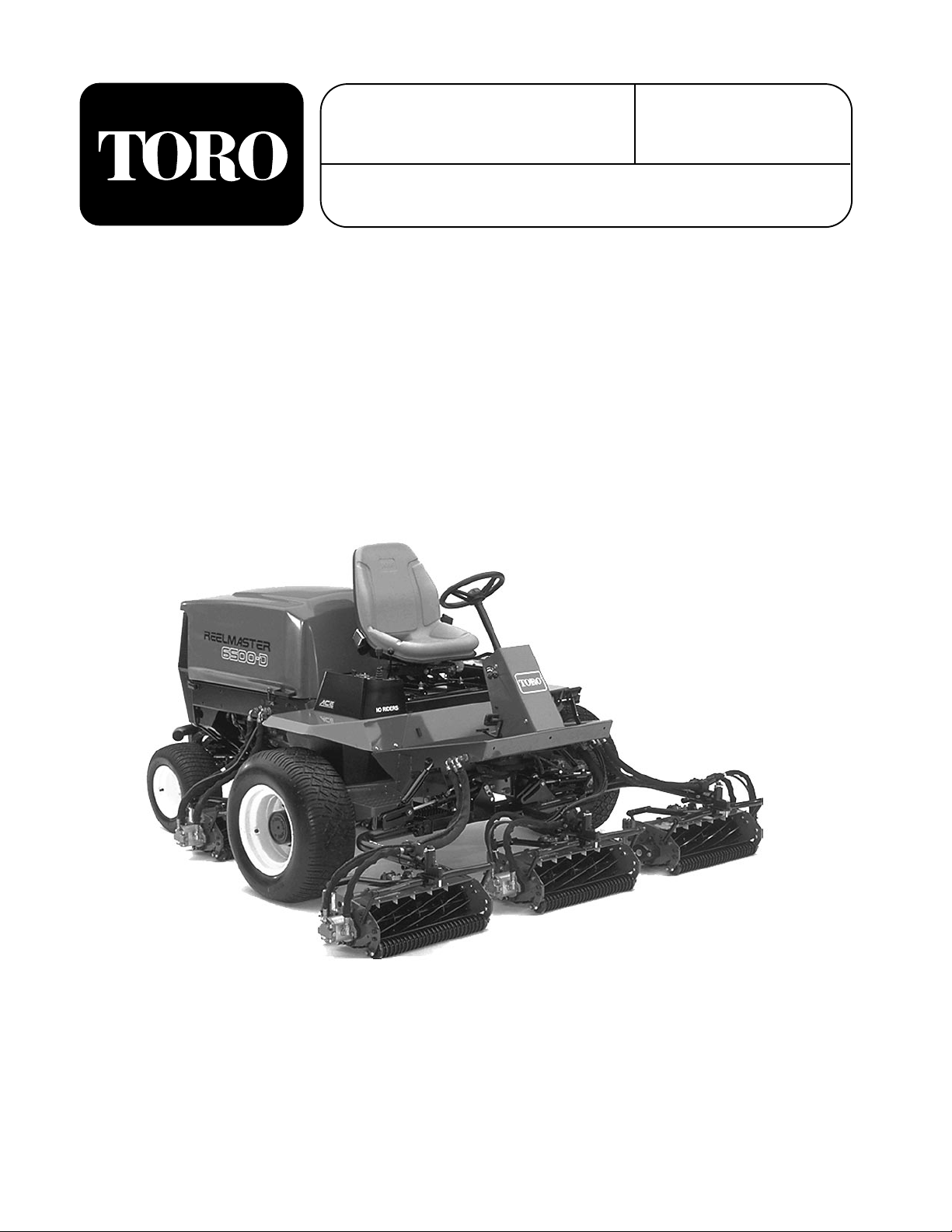
FORM NO. 3318-286 GB Rev A
®
MODEL NO. 03800TE—60001 & UP
MODEL NO. 03801TE—6
0001
& UP
REELMASTER
2- & 4-WHEEL DRIVE TRACTION UNITS
OPERATOR’S
MANUAL
®
6500-D
© The TORO Company 1995
Page 2

Table of Contents
IDENTIFICATION & ORDERING 2
SAFETY INSTRUCTIONS 4
SYMBOL GLOSSARY 7
SPECIFICATIONS 10
BEFORE OPERATING 11
Check the Engine Oil 11
Check the Cooling System 11
Fill the Fuel Tank 12
Check the Hydraulic Fluid 12
Check the Planetary Gear Drive Oil 14
Check the Rear Axle Lubricant (Model 03801) 14
Check the Tire Pressure 14
Check Reel-To-Bedknife Contact 15
Check the Torque Of the Wheel Nuts 15
KNOW YOUR CONTROLS 16
OPERATING INSTRUCTIONS 18
Starting And Stopping 18
Priming Fuel System 19
Automatic Clip Control 19
Selecting Clip Rate (Reel Speed) 20
Clip Rate Selection Chart 21
Reel Control Light 22
Pushing or Towing Machine 22
Diagnostic Light 23
Diagnostic ACE Display 23
Checking Interlock Switches 24
Hydraulic Solenoid Valve Functions 26
Height-of-Cut Selection Potentiometer
Replacement 26
Operating Characteristics 27
MAINTENANCE 28
Greasing Bearings And Bushings 28
Service Interval Chart 29
Air Cleaner Maintenance 30
Engine Oil And Filter 31
Fuel System 32
Engine Cooling System 32
Engine Fan Belt 32
Changing Hydraulic Fluid 33
Replacing Hydraulic Filter 33
Checking Hydraulic Lines And Hoses 34
Adjusting Traction Drive For Neutral 34
Adjusting Cutting Unit Lift Rate 35
Adjusting Service Brakes 35
Changing Planetary Gear Drive Oil 35
Rear Wheel Toe-in 36
Fuses 37
Backlapping 37
PREPARATION FOR SEASONAL STORAGE 48
2
Page 3

Safety
Training
1. Read the instructions carefully. Be familiar with the
controls and the proper use of the equipment.
2. Never allow children or people unfamiliar with these
instructions to use the lawn mower. Local regulations may restrict the age of the operator.
3. Never mow while people, especially children, or
pets are nearby.
4. Keep in mind that the operator or user is responsible
for accidents or hazards occurring to other people or
their property.
5. Do not carry passengers.
6. All drivers should seek and obtain professional and
practical instruction. Such instruction should emphasize:
• the need for care and concentration when working with ride-on machines;
• control of a ride-on machine sliding on a slope
will not be regained by the application of the
brake. The main reasons for loss of control are:
– insufficient wheel grip;
– being driven too fast;
to be used and remove all objects which may be
thrown by the machine.
3. WARNING—Petrol is highly flammable.
• Store fuel in containers specifically designed
for this purpose.
• Refuel outdoors only and do not smoke while
refueling.
• Add fuel before starting the engine. Never
remove the cap of the fuel tank or add petrol
while the engine is running or when the engine
is hot.
• If petrol is spilled, do not attempt to start the
engine but move the machine away from the
are of spillage and avoid creating any source of
ignition until petrol vapors have dissipated.
• Replace all fuel tanks and container caps
securely.
4. Replace faulty silencers.
Operation
1. Do not operate the engine in a confined space where
dangerous carbon monoxide fumes can collect.
2. Mow only in daylight or in good artificial light.
– inadequate braking;
– the type of machine is unsuitable for its
task;
– lack of awareness of the effects of ground
conditions, especially slopes;
– ##incorrect hitching and load distribution.
Preparation
1. While mowing, always wear substantial footwear
and long trousers. Do not operate the equipment
when barefoot or wearing open sandals.
2. Thoroughly inspect the area where the equipment is
3. Before attempting to start the engine, disengage all
blade attachment clutches and shift into neutral.
4. Do not use on slopes of more than:
• Never mow side hills over 5°
• Never mow uphill over 10°
• Never mow downhill over 15°
5. Remember there is no such thing as a “safe” slope.
Travel on grass slopes requires particular care. To
guard against overturning:
• do not stop or start suddenly when going up or
downhill;
3
Page 4

• engage the clutch slowly, and always keep the
machine in gear, especially when travailing
downhill;
• machine speeds should be kept low on slopes
and during tight turns;
• stay alert for bumps and hollows and other hidden hazards;
• never mow across the face of the slope, unless
the lawn mower is designed for this purpose.
6. Use care when pulling loads or using heavy equip-
ment.
• Use only approved drawbar hitch points.
• Limit loads to those you can safely control.
14. Stop the engine and disengage the drive to the
attachment
• before refueling;
• before removing the grass catcher;
• before making height adjustments unless the
adjustment can be made from the operator’s
position.
• before clearing blockages;
• before checking, cleaning or working on the
lawnmower;
• after striking a foreign object. Inspect the
lawnmower for damage and make repairs
before restarting and operating the equipment.
• Do not turn sharply. Use care when reversing.
• Use counterweight(s) or wheel weights when
suggested in the instruction handbook.
7. Watch out for traffic when crossing or near road-
ways.
8. Stop the blades rotating before crossing surfaces
other than grass.
9. When using any attachments, never direct discharge
of material toward bystanders nor allow anyone near
the machine while in operation .
10. Never operate the lawn mower with defective
guards, shields or without safety protective devices
in place.
11. Do not change the engine governor settings or over-
speed the engine. Operating the engine at excessive
speeds may increase the hazard of personal injury.
15. Reduce the throttle setting during engine runout and,
if the engine is provided with a shutoff valve, turn
the fuel off at the conclusion of mowing.
Maintenance and Storage
1. Keep all nuts, bolts and screws tight to be sure the
equipment is in safe working condition.
2. Never store the equipment with petrol in the tank
inside a building where fumes may reach an open
flame or spark.
3. Allow the engine to cool before storing in any enclo-
sure.
4. To reduce the fire hazard, keep the engine, silencer,
battery compartment and petrol storage area free of
grass, leaves, or excessive grease.
5. Check the grass catcher frequently for wear or dete-
rioration.
12. Before leaving the operator’s position:
• disengage the power take-off and lower the
attachments;
• change into neutral and set the parking brake;
• stop the engine and remove the key.
13. Disengage the drive to attachments when transport-
ing or not in use.
4
6. Replace worn or damaged parts for safety.
7. If the fuel tank has to be drained, this should be
done outdoors.
8. Be careful during adjustment of the machine to pre-
vent entrapment of the fingers between moving
blades and fixed parts of the machine.
9. On multi-bladed machines, take care as rotating one
Page 5

blade can cause other blades to rotate.
Sound & Vibration Levels
10. When the machine is to be parked, stored or left
unattended, lower the cutting means unless a positive mechanical lock is used.
Sound Levels
This unit has an equivalent continuous A-weighted
sound pressure at the operator ear of: 82 dB(A), based
on measurements of identical machines per 84/538/EEC.
Vibration Levels
This unit has a vibration level of 2.5 m/s2at the posterior, based on measurements of identical machines per
ISO 2631 procedures.
2
This unit does not exceed a vibration level of 0.5 m/s
the posterior based on measurements of identical
machines per ISO 2631 procedures.
at
5
Page 6
Symbol Glossary
Caustic liquids,
chemical burns to
fingers or hand
Crushing of
whole body,
applied from
above
Cutting or
entanglement of
foot, rotating auger
Poisonous
fumes or toxic
gases, asphyxiation
Crushing of
torso, force
applied from side
Severing of
foot, rotating
knives
Electrical shock,
electrocution
Crushing of fingers
or hand/, force
applied from side
Severing of
fingers or hand,
impeller blade
High pressure
fluid, injection
into body
force applied
from side
Wait until all
machine
components have
completely stopped
before touching them
High pressure
spray, erosion of
flesh
Crushing of
whole body
Severing of
fingers or hand,
engine fan
High pressure
spray, erosion of
flesh
Crushing of
head, torso and
arms
Whole body entanglement,
implement input drive line
Crushing of
fingers
or hand,
force
applied from
above
Cutting of
fingers or hand
Crushing of
toes or foot, force
applied from above
Cutting of footCrushing of leg,
Fingers or
hand entangle-
ment, chain drive
Hand & arm
entanglement,
belt drive
Explosion Fire or open
Shut off engine
& remove key before
performing mainten-
ance or repair work
Thrown or fly-
ing objects, whole
body exposure
flame
Riding on this
machine is allowed
only on a passen-
ger seat & only if the
driver’s view is not
hindered
Thrown or
flying objects,
face exposure
Secure lifting
cylinder with locking
device before getting
in hazardous area
Consult
technical manual
for proper service
procedures
Runover/back-
over, (relevant
machine to appear
in dashed box)
Stay a safe
distance from
the machine
Fasten seat belts Safety alert
Machine tipping,
riding mower
Stay clear of
articulation area
while engine is
running
Machine rollover,
ROPS (relevant
machine to appear
in dashed box)
Stored energy
hazard, kickback
or upward motion
Do not open
or remove safety
shields while
engine is
running
triangle
Do not step on
loading platform if
PTO is connected to tractor
& engine is running
outline safety
alert symbol
Hot surfaces,
burns to fingers
or hands
Do not step
Read operator’s
manual
6
Page 7
Eye protection
must be worn
Head protection
must be worn
Hearing
protection must
be worn
Caution, toxic
risk
First aid
Flush with water Engine Transmission
Fire, open light
& smoking
prohibited
Level
indicator
Engage Disengage
Horn Battery charging
Hydraulic
system
Liquid level Filter Temperature Failure/
Attachment
lower
condition
Hourmeter/elapsed
operating hours
Brake system
Oil Coolant (water) Intake air Exhaust gas Pressure
Malfunction
Attachment
raise
Fast Slow Continuous
Spacing distance Snow thrower,
Start switch/
mechanism
collector auger
variable, linear
On/start Off/stop
Plus/increase/
positive polarity
Volume empty Volume full
Minus/decrease/
negative polarity
Machine travel
direction,
forward/rearward
Jack or
support point
Draining/
emptying
Control lever
operating
direction, dual
direction
Control lever
operating
direction, multiple
direction
Engine lubricating oil
Clockwise
rotation
Engine lubricating
oil pressure
Counter-clockwise rotation
Engine lubricating
oil level
Grease
lubrication
point
Engine lubricating
oil filter
Oil lubrication
point
Engine
lubricating oil
temperature
Lift point
Engine coolant
7
Page 8
Engine coolant
pressure
Engine coolant f
ilter
n/min
Engine failure/
malfunction
Transmission
failure/malfunction
Engine rotational
speed/frequency
Clutch Neutral High Low Forward Reverse Park
231
First gear Second gear
Engine
lubricating oil
pressure
Choke Primer (start aid) Electrical preheat
Engine intake/
combustion air
Engine intake/
combustion air
pressure
(low temperature
start aid)
Engine intake/
air filter
Transmission oil Transmission oil
Engine start Engine stop
pressure
Transmission oil
temperature
NHLFRP
Third gear (other #'s
may be used until
the maximum # of forward gears is reached.)
Hydraulic oil Hydraulic oil
Hydraulic oil
pressure
Hydraulic oil level Hydraulic oil filter
temperature
Hydraulic oil
failure/malfunction
Headlights Lock Unlock Differential lock 4-Wheel drive Power Take-Off Power Take-Off,
Reel cutting
element, height
adjustment
Parking brake Fuel Fuel level Fuel filter Fuel system
Traction Above working
temperature range
Drilling Manual metal arc
0430 weight Do not dispose
welding
in the garbage
failure/malfunction
Manual 0356 Water pump
CE logo
Diesel fuel Unleaded fuel
rotational speed
Reel cutting
element
0626 Keep dry
8
Page 9

Specifications
Engine: Peugeot, 4-cylinder, 4-cycle, overhead cam, 116
cu. in (1.9 liter) displacement liquid-cooled diesel engine.
38 hp (28 kW); governed to 2500 rpm high idle; 23.5:1
compression ratio, 3.27" (83 mm) bore x 3.46" (88 mm)
stroke. Automatic glow plug/starter interlock system.
Heavy-duty, 2-stage, remote air cleaner.
Main Frame: All-welded formed steel frame, includes
tie-down loops.
Cooling System: Rear-mounted, cross-flow agricultural
type radiator; 7 fins per inch. 7.1 liter capacity. Air to
oil cooler mounted to the rear of the radiator tips outward
for cleaning. Removable oil cooler/radiator screen.
Fuel System: Rotary fuel injection pump with energizedto-run (ETR) fuel flow solenoid. Replaceable spin-on
fuel filter/water separator with water sensor. Fuel capacity: 64 liter.
Traction System: Servo-controlled hydrostatic system
driving double-planetary, gear-reduction, front-wheel drives. Foot pedal control of forward/reverse ground speed.
Toro 4-MaticR 4-Wheel Drive System only: Rear drive
axle coupled to hydrostatic transmission via an overrunning clutch for full-time, on-demand 4-wheel drive. A
Roll Over Protective Structure and seat belt are standard.
Ground Speed: 0–10 mph forward; 0–4 mph reverse.
Cutting Unit Drive System: Reel motors feature quick
disconnect for removal or installation onto the cutting
unit. Cutting units can be driven from either end.
Seat: Deluxe high-back suspension seat with adjustable
fore and aft travel, weight and height. Tool box at the left
side of the seat.
Steering System: Power steering with dedicated power
source.
Tires: Two rear steering tires: 20 x 10.00–10, tubeless, 6ply rating. Two front traction drive tires: 29 x 12.00–15
tubeless, 6-ply rating. Recommended tire pressure for
front and rear tires is 15–20 psi.
Brakes: Individual totally enclosed, multi-disc, wet brakes
and parking brakes on front traction wheels. Hydrostatic
braking through traction drive.
Electrical Features: 12-volt, 530 cold-cranking amperes
at 0° F (–18° C), 85-minute reserve capacity at 80° F (27°
C), maintenance-free battery. 55-amp alternator with l° C
regulator/rectifier. Automotive-type electrical system. Seat
switch, reel and traction interlock switches.
Controls: Foot-operated traction and brake pedals. Hand
operated throttle, speed control lever, parking brake lock,
ignition switch with automatic preheat cycle, single joy
stick control for cutting unit on/off and lift lower. Cutting
unit backlap switch under the operator's seat. Height-of-cut
selector knob located under the control panel.
Gauges: Hour meter, speedometer, fuel gauge, temperature
gauge, 4-bank warning lamp: oil pressure, water temperature, amps, and glow plug. 2-bank warning lamp: water in
fuel, water level.
Diagnostics; The Automatic Control Electronics, ACET
system allows precise timing and control of machine functions for maximum reliability. Toro standard diagnostic
display connects to an electronic control unit to pinpoint
any electrical problems quickly and easily. Available
DATA LOGT system allows mechanic to find intermittent
problems.
General Specifications (approx.):
Width-of-Cut: 244 cm
Overall Width:
Transport 213 cm
Operational 279 cm
Overall Length: 305 cm
Height:
Without roll-over protection system installed:152 cm
With roll-over protection system installed: 213 cm
Weight:
Model 03800 1,194 kg*
Model 03801 1,232 kg*
*With 5-Blade Cutting Units & full fluid levels
9
Page 10
Before Operating
CAUTION
Before servicing or making adjustments to the machine,
stop the engine and remove the key from the switch.
CHECK THE ENGINE OIL (Fig. 2 & 3)
Crankcase capacity is 5 l with filter.
➀
1. Park the machine on a level surface. Release the hood latch
and open the hood.
2. Remove the dipstick from the tube cap, wipe clean and rein-
stall the dipstick into the tube cap. Pull it out again and check
the oil level on the dipstick: The oil level must always be in the
notch area on the dipstick.
3. If the oil level is low, remove the tube cap and add SAE 15W-
40 CD oil until the level reaches top of notch on the dipstick.
DO NOT OVERFILL.
4. Install the oil tube cap.
5. Close the hood and secure the latch.
CHECK THE COOLING SYSTEM (Fig. 4)
CAUTION
If the engine has been running, pressurized hot coolant
can escape and cause burns if the degasser cap is
removed. Allow the engine to cool at least 15 minutes or
until the degasser cap is cool enough to touch without
burning your hand.
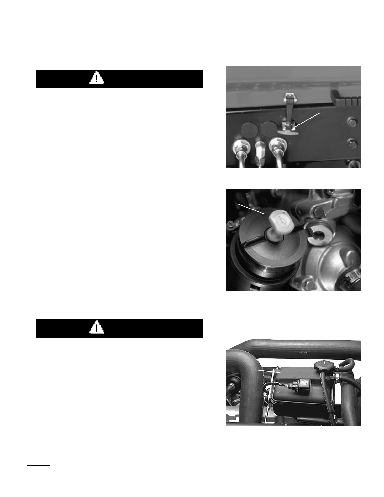
1. Hood latch
Figure 2
➀
Figure 3
1. Dipstick/tube cap
➀
Capacity of the system is 13 l.
Check the cooling system if the low water level light illuminates.
1. Park the machine on a level surface. Release the hood latch
and open the hood.
10
1. Degasser tank
Figure 4
Page 11

2. Remove the degasser tank cap and check the coolant level. The
level should be up to or above the tabs in the degasser tank,
when the engine is cold.
3. If coolant is low, remove the degasser tank cap and add a 50/50
mixture of water and Peugeot-recommended anti-freeze (Toro
Part No. 93-7213). DO NOT USE WATER ONLY OR ALCOHOL/METHANOL BASE COOLANTS.
4. Install the degasser tank cap.
5. Close the hood and secure the latch.
FILL THE FUEL T ANK (Fig. 5)
Fuel tank capacity is 56 liters.
1. Remove the fuel tank cap.
2. Fill the tank to about one inch below the top of the tank (not
the filler neck) with No. 2 diesel fuel. Then install the cap.
➀
Figure 5
1. Fuel tank cap
DANGER
Because diesel fuel is flammable, use caution when storing or handling it. Do not smoke while filling the fuel
tank. Do not fill the fuel tank while the engine is running, hot, or when the machine is in an enclosed area.
Always fill the fuel tank outside and wipe up any spilled
diesel fuel before starting the engine. Store fuel in a
clean, safety-approved container and keep the cap in
place. Use diesel fuel for the engine only; not for any
other purpose.
CHECK HYDRAULIC FLUID (Fig. 6)
The hydraulic system is designed to operate on anti-wear hydraulic
fluid. The machine’s reservoir is filled at the factory with approximately 32 liters of Mobil 424 hydraulic fluid. Check the level of
hydraulic fluid before the engine is first started and daily thereafter.
Group 1 Hydraulic Fluid (Recommended for ambient temperatures
consistently below 38° C.):
➀
ISO type 46/68 anti-wear hydraulic fluid
Mobil Mobil Fluid 424
Amoco Amoco 1000
1. Hydraulic tank cap
Figure 6
11
Page 12

International Harvester Hy-Tran
Texaco TDH
Shell Donax TD
Union OIl Hydraulic/Tractor Fluid
Chevron Tractor Hydraulic Fluid
BP Oil BP HYD TF
Boron OIl Eldoran UTH
Exxon Torque Fluid
Conoco Power-Tran 3
Kendall Hyken 052
Phillips HG Fluid
Note: The fluids within this group are interchangeable.
Group 2 Hydraulic Fluid (Biodegradable):
ISO VG 32/46 anti-wear hydraulic fluid
Mobil EAL 224 H
Note: The fluid in this group is not compatible with the fluids
in group 1.
IMPORTANT: These hydraulic fluids are specified to allow
optimal operation of the machine in a wide range of temperatures encountered. The group 1 fluids are a multi-viscosity
hydraulic fluids which allows operation at lower temperatures
without the increased viscosity, which is associated with straight
viscosity fluids.
Note: When changing from one type of hydraulic fluid to the other,
be certain to remove all the old fluid from the system, because
some brands of one type are not completely compatible with
some brands of the other type of hydraulic fluid.
IMPORTANT: Use only types of hydraulic fluids specified.
Other fluids could cause system damage.
Note: A red dye additive for the hydraulic system fluid is available
in 20 ml bottles. One bottle is sufficient for 15–23 l. of
hydraulic fluid. Order Part No. 44-2500 from your Authorized
Toro Distributor
1. Position the machine on a level surface, lower the cutting units
and stop the engine.
2. Clean the area around the filler neck and the cap of the
hydraulic tank. Remove the cap from the filler neck.
3. Remove the dipstick from the filler neck and wipe it with a
clean cloth. Insert the dipstick into the filler neck; then remove
it and check the level of fluid. Fluid level should be within 0.6
cm of the mark on the dipstick.
12
Page 13

4. If the level is low, add fluid to raise the level to the full mark.
5. Install the dipstick and cap onto the filler neck.
CHECK THE PLANETARY GEAR DRIVE
OIL (Fig. 7)
Check the oil if external leakage is noted. Use high-quality SAE
85W-140 wt. gear lubrication as replacement.
System capacity is 47.3 cl.
1. With the machine on a level surface, position the wheel so the
check/drain plug is at either three or nine o'clock position.
2. Remove plug. Oil should be to bottom of the hole.
3. Add gear oil, if necessary, to bring fluid up to the correct level
and install the plug.
4. Repeat steps 1–3 on the opposite gear assembly.
CHECK REAR AXLE LUBRICANT
(Model 03801 Only) (Fig. 8)
The rear axle is shipped from the factory filled with SAE 85W-140
wt. gear lubrication. Check the level before the engine is first started and every 400 hours thereafter. Capacity is 2.3 l. Visually inspect
for leaks daily.
➀
Figure 7
1. Check/Drain plug
➀
➁
Figure 8
1. check plug
2. Fill plug
1. Position the machine on a level surface.
2. Remove a check plug from one end of the axle and make sure
lubricant is up to bottom of hole. If the level is low, remove the
fill plug and add enough lubricant to bring the level up to the
bottom of the check plug holes.
CHECK TIRE PRESSURE
The tires are over-inflated for shipping. Therefore, release some of
the air to reduce the pressure. Correct air pressure in the front and
rear tires is 103–138 kPa.
IMPORTANT: Maintain even pressure in all tires to assure a
good quality-of-cut and proper machine performance. DO NOT
UNDER INFLATE.
13
Page 14

CHECK REEL-TO-BEDKNIFE CONTACT
Each day before operating, check reel-to-bedknife contact, regardless of whether the quality of cut had previously been acceptable.
There must be light contact across the full length of the reel and
bedknife (refer to Adjusting Reel to Bedknife in Cutting Unit
Operator's Manual).
CHECK THE TORQUE OF WHEEL NUTS
OR BOLTS
CAUTION
Torque the front wheel nuts to 61–74 kPa and the rear
wheel nuts to 115–135 kPa after 1–4 hours of operation
and again after 10 hours of operation and every 200 hours
thereafter. Failure to maintain proper torque could result
in failure or loss of the wheel and may result in personal
injury.
14
Page 15

Controls
Traction Pedal (Fig. 9)—Controls forward and reverse operation.
Depress the top of the pedal to move forward and bottom to move
backward. Ground speed depends on how far the pedal is depressed.
For no-load, maximum ground speed, fully depress the pedal while
the throttle is in FAST.
➃
➂
To stop, reduce foot pressure on traction pedal and allow it to return
to center position.
Traction Speed Limiter (Fig. 9)—Preset this lever to limit the
amount the traction pedal can be depressed in the forward direction
to maintain a constant mowing speed.
Reel Control Light (Fig. 9)—When lit, indicates the machine is
being operated in a way in which the automatic reel speed control
cannot obtain the desired clip.
Speedometer (Fig. 9)—Indicates ground speed at which the
machine is traveling.
Lower Mow/Raise Control Lever (Fig. 10)—The lever raises and
lowers the cutting units and also starts and stops the reels.
Fuel Gauge (Fig. 10)—Indicates the level of fuel in the tank.
Engine Oil Pressure Warning Light (Fig. 10)—Indicates danger-
ously low engine oil pressure.
Key Switch (Fig. 10)—Three positions: OFF, ON / Preheat and
START.
WARNING
The engine will not crank over until the glow plug lamp
goes out. Glow plugs must complete their cycle before
the controller will allow the engine to crank.
Throttle Control (Fig. 10)—Move the control forward to increase
engine speed, rearward to decrease speed.
➂
1. Traction pedal
2. Traction speed limiter
3. Reel control light
4. Speedometer
2
12
Figure 9
11
4
5
7
6
1
9
Figure 10
1. Lower mow/raise control lever
2. Fuel gauge
3. Engine coolant temperature gauge
4. Engine oil pressure warning light
5. Engine coolant temperature warning light
6. Glow plug indicator light
7. Charge indicator
8. Key switch
9. Throttle control
10. Enable/disable switch
11. Water-in-fuel light
12. Low-water level light
10
➀
3
8
Engine Coolant Temperature Warning Light (Fig.10 )—The light
illuminates and the engine shuts down when coolant reaches a dangerously high temperature.
Glow Plug Indicator Light (Fig. 10)—When lit, indicates the glow
plugs are on.
Charge Indicator (Fig. 10)—Illuminates when the system charging
circuit malfunctions.
15
Page 16

Enable/Disable Switch (Fig. 10)—Used with lower mow / raise
control lever to operate the reels.
Water-in-the-fuel Light (Fig. 10)—Warns of water in the fuel system.
Low Water Level Light (Fig. 10)—Warns that the coolant water
level is low.
Height-of-Cut Selector Knob (Fig. 11)—Turning the knob to the
appropriate setting informs the electronic controller at what heightof-cut the machine is being operated so desired clip may be
obtained. See section in manual for operating instructions. The knob
is located under the control panel.
Hour Meter (Fig. 11)—Shows total hours the machine has been
operated.
Backlap Switch (Fig. 12)—Used with the lower mow / raise control lever for backlapping operation. This switch is located under
seat plate. Refer to Cutting Unit Maintenance, Backlapping.
Brake Pedals (Fig. 13)—Two foot pedals operate individual wheel
brakes for turning assistance, parking and to aid better sidehill traction. Alocking pin connects the pedals for parking brake operation
and transport.
➁
➀
Figure 11
1. HOC selector knob
2. Hour meter
➀
Parking Brake Latch (Fig. 13)—A knob on the left side of the
console actuates the parking brake lock. To engage the parking
brake, connect the pedals with the locking pin, push down on both
pedals and pull the parking brake latch out. To release the parking
brake, depress both pedals until the parking brake latch retracts.
Seat (Fig. 14)—Seat adjusting lever allows 10 cm fore and aft
adjustment. Seat adjusting knob adjusts seat for operator’s weight.
To adjust the seat fore and aft, pull the lever on the left side of the
seat assembly outward. After moving the seat, release the lever to
lock the seat into position. To adjust for operator’s weight, turn the
spring tension knob: clockwise to increase tension, counterclockwise to decrease spring tension
1. Backlap switch
➁
1. Brake pedals
2. Parking brake latch
3. Locking pin
Figure 12
➂
➀
Figure 13
16
Page 17

①
①
Operating Instructions
CAUTION
Before servicing or making adjustments to the machine,
stop the engine and remove the key from the switch.
STARTING AND STOPPING
1. Sit on the seat; keep your foot off the traction pedal. Assure
the parking brake is engaged, the traction pedal is in NEUTRAL, the throttle is in the SLOW position and the ENABLE/
DISABLE switch is in the DISABLE position.
1. Seat adjusting lever
Figure 14
2. Seat adjusting knob
WARNING
The engine will not crank over until the glow plug lamp
goes out. Glow plugs must complete their cycle before
the controller will allow the engine to crank.
2. Turn the ignition switch to ON/Preheat position. An automatic
timer will control preheat for approximately 6 seconds. The
engine will not crank until preheat light goes off. After preheat,
turn the key to START position. CRANK THE ENGINE FOR
NO LONGER THAN 15 SECONDS. Release the key when
the engine starts. If additional preheat is required, turn the key
to the OFF position, then to ON/preheat position. Repeat this
process as required.
17
Page 18

3. Run the engine at idle speed or partial throttle until the engine
warms up.
4. To stop, move all controls to NEUTRAL and set the parking
brake. Return the throttle to the idle position, turn the key to
OFF and remove it from the switch.
PRIMING THE FUEL SYSTEM
(Fig. 15 & 16)
IMPORTANT: The fuel system may need to be primed when a
new engine is started for the first time, if it runs out of fuel or if
maintenance is performed on the fuel system.
1. Unlatch and raise the hood.
2. Insert a 3/16" hose over the bleed screw and run the other end
into a container to catch the fuel.
3. Loosen the fuel filter/water separator bleed screw (Fig. ) a few
turns. Pump the priming plunger until a steady stream of fuel
comes out of the hole in the bleed screw. When the fuel stops
foaming, tighten the bleed screw during the downstroke of the
priming plunger. Wipe up any spilled fuel.
4. Pump the priming plunger until you feel resistance. Try to start
the engine. If the engine does not start, repeat step 3.
➁
➀
Note: It may be necessary to bleed the air out of the fuel line
between the fuel filter/water separator and the injection pump. To
do this, loosen the fitting on the injection pump (Fig. 16) and repeat
the bleeding procedure.
AUTOMATIC CLIP CONTROL
The RM 6500-D is equipped with an electronic controller which is
programmed to achieve automatic clip control. The machine will
automatically adjust the reel speed to attain the desired clip as the
traction speed changes. For the controller to know what clip is
desired, the software must have been properly set, by your distributor or dealer, to either 5 or 11 blade and the height-of-cut selector
knob must be properly set.
The range of possible reel speeds is a minimum of about 500 RPM
and a maximum of about 1400 RPM. As long as the desired clip
requires a reel speed within this range, the machine will maintain
the desired clip. If the traction speed is too slow or too fast to allow
the desired clip, the Reel Control light (on the front control panel)
1. Primer plunger
Figure 15
2. Bleed screw
➀
Figure 16
1. Injection pump fitting
18
Page 19

will illuminate, warning that the desired clip is not being maintained. For example, if the traction speed is zero, the reels will still
run at the minimum speed of about 500 RPM, which will result in a
clip smaller than desired and cause the Reel Control light to illuminate. The approximate ranges of traction speed which will result in
the desired clip are as follows for several of the possible heights of
cut:
SAMPLES OF TRACTION SPEED RANGES FOR VARIOUS HEIGHTS OF CUT
No. of Blades
per C.U.
11
11
5
5
* Procedure for maintaining proper clip rate:
1. Set HOC selector knob to correct letter setting (Per chart located under seat plate).
2. Maintain ground speed which prevents reel control light from illuminating
Height of Cut
.97 cm
1.27 cm
1.60 cm
2.24 cm
Minimum T raction
SELECTING CLIP RATE (REEL SPEED)
To achieve a consistent, high quality of cut, and a uniform after-cut
appearance, the reel speed be matched to the height of cut. The
machine controller is programmed to automatically control the reel
speed to give the correct clip, even as traction speed changes. To
control the reel speed, the controller must know the height of cut of
the machine, and whether the machine is equipped with 5- or 11blade reels.
1. Height-of-cut selector knob
Figure 17
Speed
3 kmh
4.2 kmh
2.4 kmh
3.4 kmh
Maximum T raction
Speed
9.6 kmh
12.2 kmh
7.2 kmh
5.5 kmh
Adjust the height-of-cut selector knob as follows:
1. Insure the configuration screen, set by the distributor, is on the
correct setting. (5 or 11 blade.)
2. Verify the height-of-cut setting on the cutting units. Using the
column of the chart above or the chart under the seat plate, listing either 5- or 11-blade reels, find the height of cut listing
nearest the actual height-of-cut setting. Look across the chart
to find the letter corresponding to that height of cut.
3. Turn the height-of-cut selector knob to the letter setting deter-
mined in step 2.
4. Operate the machine for several days, then examine the cut to
➀
19
Page 20

ensure satisfaction with the quality of cut. The height-of-cut
knob may be set one position on either side of the position on
the chart to account for differences in grass condition, grass
length removed, and personal preference of the superintendent.
For a cut with more grass removed but slightly more clip visibility, move the height-of-cut selector knob one position higher
than specified. For a cut with less grass removed and slightly
less clip visibility, move the height-of-cut selector one position
lower than specified.
Full Speed—There may be times when it is desirable for the reels
to run at full speed regardless of the machine’s traction speed.
Examples of this are vertical cutting or heavy scalping. In such
cases, the height-of-cut selector knob may be set to position "A"
which will command the machine controller to run the reels at full
speed at all times.
CLIP RATE (REEL SPEED) SELECTION CHART
11-Blade Cutting Unit 8-Blade Cutting Unit
Height-of-Cut Knob
Selection
A
B
C
D
E
F
G
H
I
J
K
L
M
N
O
P
FULL SPEED—Cutting units will always run at full speed in this position
Height of Cut
FULL SPEED
9.6 mm
10.7 mm
11.7 mm
12.7 mm
13.7 mm
14.7 mm
15.7 mm
16.8 mm
17.8 mm
18.8 mm
19.8 mm
20.8 mm
21.8 mm
22.9 mm
23.9 mm
Height-of-Cut Knob
Selection
A
B
C
D
E
F
G
H
I
J
K
L
M
N
O
P
Height of Cut
FULL SPEED
16.0 mm
17.3 mm
18.5 mm
19.6 mm
20.8 mm
21.8 mm
22.9 mm
23.9 mm
24.9 mm
25.9 mm
26.9 mm
27.9 mm
29.0 mm
30.1 mm
31.0 mm
20
Page 21

REEL CONTROL LIGHT
The Reel Control light, located on the front control panel, is used to
give feedback to the operator whether the machine controller can
achieve the desired clip. If the machine is operated at a traction
speed that is too low or too high, the machine controller may not be
able to set the reel speed at the required value for the desired clip.
If this occurs, the Reel Control light will illuminate.
If the Reel Control light illuminates, it means one of the following
things:
1. The machine is being operated at a traction speed too slow to
allow desired clip.
or
2. The machine is being operated at a traction speed too fast to
allow desired clip. To correct the situation, change the traction
speed until the light goes out.
or
3. A foreign object, such as a stick, piece of turf, etc. is restricting
reel rotation.
If changing the traction speed or removing the foreign object does
not cause the light to go out, and the Reel Control light remains
illuminated regardless of traction speed, then a service issue is indicated. In this case, refer to the Diagnostic Display section of this
manual, check the service manual or contact your local authorized
Toro Distributor.
PUSHING OR TOWING THE MACHINE
In an emergency, the Reelmaster 6500-D can be moved by actuating
the by-pass valve in the variable displacement hydraulic pump and
pushing or towing the machine.
IMPORTANT: Do not push or tow the machine faster than 2–3
mph (3-4.8 km/hr) because internal transmission damage may
occur. The by-pass valve must be open whenever the machine is
pushed or towed.
1. The by-pass valve is located on the top of variable displace-
ment pump (Fig. 18). Rotate the valve 90° in either direction,
to open and allow oil to by-pass internally. Because fluid is
by-passed, the machine can be moved—slowly—without damaging the transmission.
2. Close the by-pass valve before starting the engine. However,
do not exceed 7–11 Nm torque to close the valve.
➀
Fig. 18
21
Page 22

IMPORTANT: Running the engine with the by-pass valve open
will cause the transmission to overheat.
DIAGNOSTIC LIGHT (Fig. 19)
The RM 6500-D is equipped with a diagnostic light which indicates
whether or not the electronic controller is functioning correctly. The
diagnostic light is located on the steering tower panel. When the
electronic controller is functioning correctly and the key switch is
moved to the ON position, the controller diagnostic light will be
illuminated for approximately 6 seconds. The light will not illuminate if the controller detects a malfunction in the electrical system.
If the diagnostic light is not illuminated when the key switch is in
the ON position, this indicates that the electronic controller is not
operating. Possible causes are:
1. Loopback connector (under control panel cover) is not con-
nected.
2. The electronic controller light is burned out.
➀
Figure 19
1. Electronic controller light
3. Fuses are blown.
4. The light is not functioning correctly.
Check electrical connections, input fuses and the diagnostic light
bulb to determine malfunction. Make sure the loopback connector is
secured to the wire harness connector.
DIAGNOSTIC ACE DISPLAY
The RM 6500-D is equipped with an electronic controller which
controls most machine functions. The controller determines what
function is required for various input switches (i.e. seat switch, key
switch, etc.) and turns on the outputs to actuate solenoids or relays
for the requested machine function.
For the electronic controller to control the machine as desired, each
of the input switches, output solenoids and relays must be connected and functioning properly.
The Diagnostic ACE display is a tool to help the user verify correct
electrical functions of the machine.
22
Page 23

CHECKING THE INTERLOCK SWITCHES
The purpose of the interlock switches is to prevent the engine from
cranking or starting unless the traction pedal is in NEUTRAL, the
Enable/Disable switch is in DISABLE and the Lower Mow/Raise
control is in the neutral position. In addition, the engine will stop
when the traction pedal is depressed with the operator off the seat.
To verify interlock switch function:
CAUTION
THE INTERLOCK SWITCHES ARE FOR THE
PROTECTION OF THE OPERATOR AND
BYSTANDERS, AND TO ENSURE CORRECT
OPERATION OF THE MACHINE, SO DO NOT
BYPASS OR DISCONNECT THEM. CHECK
THEIR OPERATION DAILY TO INSURE THEY
ARE OPERATING CORRECTLY. IF A SWITCH
IS DEFECTIVE, REPLACE IT BEFORE OPERATING THE MACHINE. HOWEVER, DO NOT
RELY ENTIRELY ON SAFETY SWITCHES,
ALSO USE COMMON SENSE!
1. Park the machine on a level surface, lower the cutting units,
stop the engine and engage the parking brake.
2. Open the control panel cover. Locate the wire harness and con-
nector. Carefully unplug the loopback connector from the harness connector.
3. Connect the Diagnostic ACE display connector to the harness
connector. Make sure the correct overlay decal is positioned on
Diagnostic ACE display.
➀
Figure 20
1. Wire harness and connectors
➀
Figure 21
1. Diagnostic ACE
4. Turn the key switch to the ON position, but do not start the
machine.
Note: The red text on the overlay decal refers to input switches
and the green text refers to outputs.
5. The “inputs displayed” LED, on lower right column of the
Diagnostic ACE, should be illuminated. If the “outputs displayed” LED is illuminated, press and release the toggle button
on the Diagnostic ACE to change the LED to “inputs displayed". Do not hold the button down.
23
Page 24

6. The Diagnostic ACE will illuminate the LED asso-
ciated with each of the inputs when that input
switch is closed.
Individually, change each of the switches from open
to closed (i.e., sit on seat, engage the traction pedal,
etc.), and note that the appropriate LED on
Diagnostic ACE will blink on and off when corresponding switch is closed. Repeat on each switch
that is possible to be changed by hand.
7. If switch is closed and appropriate LED does not
turn on, check all wiring and connections to switch
and/or check switches with an ohm meter. Replace
any defective switches and repair any defective
wiring.
The Diagnostic ACE also has the ability to detect which
output solenoids or relays are turned on. This is a quick
way to determine if a machine malfunction is electrical
or hydraulic.
To verify output function:
Note: It may be necessary to toggle between
“inputs displayed” and “outputs displayed” several
times to do the following step. To toggle back and
forth, press the toggle button once. This may be
done as often as required. DO NOT HOLD THE
BUTTON.
6. Sit on the seat and attempt to operate the desired
function of the machine. The appropriate output
LEDs should illuminate to indicate that the ECU is
turning on that function. (Refer to the list below to
be certain of the specified output LEDs.
Note: If any output LED is blinking, this indicates an
electrical problem with that OUTPUT. Repair or replace
defective electrical parts immediately. To reset a blinking LED, turn the key switch to “OFF”, then back to
“ON”.
If no output LEDs are blinking, but the correct output
LEDs do not illuminate, verify that the required input
switches are in the correct positions for the function to
occur.
1. Park the machine on a level surface, lower the cut-
ting units, stop the engine and engage the parking
brake.
2. Open the control panel cover. Locate the wire har-
ness and connectors near the controller. Carefully
unplug the loopback connector from the harness
connector. Set the height-of-cut selector knob to
position "A".
3. Connect the Diagnostic ACE connector to the har-
ness connector. Make sure the correct overlay decal
is positioned on Diagnostic ACE.
4. Turn the key switch to the ON position, but do not
start the machine.
Note: The red text on the overlay decal refers to
input switches and the green text refers to outputs.
5. The “outputs displayed” LED, on lower right col-
umn of the Diagnostic ACE, should be illuminated.
If the “inputs displayed’ LED is illuminated, press
the toggle button on Diagnostic ACE to change
LED to “outputs displayed”.
If the output LEDs are on as specified, but the machine
does not function properly, this indicates a non-electrical
problem. Repair as necessary.
Note: Due to electrical system constraints, the output
LEDs for “START”, “PREHEAT” and “ETR/ALT”
may not blink even though an electrical problem may
exist for those functions. If the machine problem appears
to be with one of these functions, check the electrical
circuit with a volt/ohm meter to verify that no electrical
problem exists to these functions.
If each input switch is in the correct position and functioning correctly, but the output LEDs are not correctly
illuminated, this indicates an ECU problem. If this
occurs, contact your Toro Distributor for assistance.
IMPORTANT: The Diagnostic ACE display must not
be left connected to the machine. It is not designed to
withstand the environment of the machine's every
day use. When finished using the Diagnostic ACE,
disconnect it from the machine and reconnect the
loopback connector to the harness connector. The
machine will not operate without the loopback connector installed on the harness. Store the Diagnostic
24
Page 25

ACE in dry, secure location in the shop, not on the
machine.
HYDRAULIC SOLENOID VALVE
FUNCTIONS
Use the list below to identify and describe the different
functions of the solenoids in the hydraulic manifold.
Each solenoid must be energized to allow function to
occur.
Solenoid Function
VS1A,S1A,S2A Front reel circuit
VS1B,S1B,S2B Rear reel circuit
VS1A,S1A,S4A,S6A Lift front wing cutting units
VS1A,S1A,S4A,S7A Lift center cutting unit
VS1A,S1A,S4A,S4B Lift rear cutting unit
S5A,S7A Lower center cutting unit
S5A,S4B lower rear cutting unit
S54,S6A Lower front wing cutting units
VS1A,S3A Backlap front cutting units
VSIB,S3B Backlap rear cutting units
the uphill wheel slips and loses traction. If this situation
occurs, depress uphill turn pedal gradually and intermittently until the uphill wheel stops slipping, thus, increasing traction on the downhill wheel.
WARNING: When operating the machine, always use
the seat belt and roll-over protection system together.
Warning System—If a warning light comes on during
operation, stop the machine immediately and correct the
problem before continuing. Serious damage could occur
if the machine is operated with a malfunction.
Mowing —Start the engine and move throttle to FAST
so the engine is running at maximum speed. Move the
ENABLE/DISABLE switch to ENABLE and use the
LOWER MOW/RAISE lever to control the cutting units
(front cutting units are timed to lower before the rear
cutting units). To move forward and cut grass, press the
traction pedal forward. Maintain a speed which does not
result in the Reel Control Light being illuminated.
Gradually increase or decrease the traction speed to
ensure proper clip is maintained.
HEIGHT-OF-CUT SELECTION
POTENTIOMETER REPLACEMENT
The height-of-cut selection potentiometer is factory calibrated. If the height-of-cut selection potentiometer must
be replaced for any reason, the new potentiometer must
be calibrated to assure the correct clip. (If the potentiometer is not calibrated correctly, the delivered clip
may be as much as 2 or 3 settings different from the
desired setting.) This calibration must be done by your
Toro distributor.
OPERATING CHARACTERISTICS
Familiarization—Before mowing grass, practice operating the machine in an open area. Start and stop the
engine. Operate in forward and reverse. Lower and raise
the cutting units and engage and disengage the reels.
When you feel familiar with the machine, practice operating up and down slopes at different speeds.
The brakes can be used to assist in turning the machine.
However, use them carefully, especially on soft or wet
grass conditions because the turf may be torn accidentally. Individual turning brakes may also be used to help
Transport—Move the ENABLE/DISABLE switch to
DISABLE, lock the brake pedals together and raise the
cutting units to the transport position. Be careful when
driving between objects so you do not accidentally damage the machine or cutting units. Use extra care when
operating the machine on slopes. Drive slowly and avoid
sharp turns on slopes to prevent roll overs. The cutting
units should be lowered when going downhill for steering control.
Selecting Clip Rate (Reel Speed)—The automatic clip
control programmed in the machine controller requires
that it be told at what height of cut the machine is being
operated and whether the machine is equipped with 5- or
11-blade reels. Refer to Selecting Clip Rate (Reel Speed.
When the machine is being operated in such a way that
it achieves the desired clip, the Reel Control light will
not light. If it does light, this indicates that the traction
speed is too low or too high for the machine to achieve
the desired clip.
25
Page 26

Maintenance
GREASING BEARINGS AND
BUSHINGS (Fig. 22–30)
The machine has grease fittings that must be lubricated
regularly with No. 2 General Purpose Lithium Base
Grease. If the machine is operated under normal conditions, lubricate all bearings and bushings after every 50
hours of operation or immediately after every washing.
1. The grease fitting locations and quantities are:
Cutting unit carrier frame and pivot (2 ea.)
(Fig. 22); Rear axle tie rod (2), Steering cylinder
ball joints (2), (Fig. 23); Front lift cylinders (2),
(Fig. 24); Front lift cylinder (1), (Fig. 25); Rear lift
cylinder pivot (2), (Fig. 26); Lift arm pivot (3),
(Fig. 27); Rear axle pivot (Fig. 28) Rear lift arm
pivots (2) (Fig. 29) and Brake pedal shaft (1)
(Fig. 30).
Figure 24
Figure 25
26
Figure 22
Figure 26
Figure 23
Figure 27
Page 27

Figure 28
Figure 30
Reelmaster 6500-D, 2-Wheel Drive Quick Reference Aid
Check/Service (daily)
1. Oil level, engine
2. Oil level, hydraulic tank
3. Coolant level, radiator
4. Fuel/Water separator
5. Air filter service indicator
6. Radiator screen
7. Brake function
8. Tire pressure
Check/Service (See
Operator’s Manual)
9. Battery
10. Belts (fan, alternator)
11. Planetary gear drive
Figure 29
Fluid
Type
Engine Oil
Hydraulic
Circuit Oil
Primary Air
Filter
Safety Air
Filter
Fuel Filter 400 hours 76-5220
Fuel Tank No. 2 Diesel 56 l Drain and flush every 2 years
Coolant 93-7213 13.25 l Drain and flush every 2 years
Planetary
Gear Drive
SAE 15W-
40CD
Mobil 424 32 l 800 hours
SAE85W140 .44 l
Capacity
5 l 100 hours 100 hours 74-7970
Fluid Filter
See service
indicator
See service
indicator
800 hours
Filter
Part No.
94-2621
93-9162
93-9163
27
Page 28

CAUTION
Before servicing or making adjustments to the machine,
stop the engine and remove the key from the switch.
GENERAL AIR CLEANER MAINTENANCE
1. Check the air cleaner body for damage which could possibly
cause an air leak. Replace a damaged air cleaner body.
2. Service the air cleaner filters whenever the air cleaner indicator
(Fig. 31) shows red or every 400 hours (more frequently in
extreme dusty or dirty conditions). Do not overservice the air
filter.
2. Be sure the cover is sealing around the air cleaner body.
SERVICING THE AIR CLEANER
1. Release the latches securing the air cleaner cover to the air
cleaner body. Separate the cover from the body. Clean inside
of the air cleaner cover.
2. Gently slide the primary filter (Fig. 33) out of the air cleaner
body to reduce the amount of dust dislodged. Avoid knocking
the filter against the air cleaner body. Do not remove the safety
filter.
1. Air cleaner indicator
➀
➁
➀
Figure 31
➀
3. Inspect the primary filter and discard it if damaged. Do not
wash or reuse a damaged filter.
IMPORTANT: Never attempt to clean a safety filter. Replace
the safety filter with a new one after every three primary filter
services.
Washing Method
A. Prepare a solution of filter cleaner and water and soak the
filter element about 15 minutes. Refer to directions on the
filter cleaner carton for complete information.
B. After soaking the filter for 15 minutes, rinse it with clear
water. Maximum water pressure must not exceed 40 psi to
prevent damage to the filter element. Rinse the filter from
clean side to dirty to side.
28
1. Air cleaner latches
Figure 32
2. Dust cup
➀
Figure 33
1. Air cleaner primary filter
Page 29

C. Dry the filter element using warm, flowing air (71° C)
max), or allow element to air-dry. Do not use a light bulb
to dry the filter element because damage could result.
Compressed Air Method
A. Blow compressed air from the inside to the outside of the
dry filter element. Do not exceed 689 kPa to prevent damage to the element.
B. Keep the air hose nozzle at least 5 cm from the filter and
move the nozzle up and down while rotating the filter element. Inspect for holes and tears by looking through the
filter toward a bright light.
5. Inspect the new filter for shipping damage. Check the sealing
end of the filter. Do not install a damaged filter.
6. Insert new filter into the air cleaner body. Make sure the filter
is sealed properly by applying pressure to the outer rim of the
filter when installing it. Do not press on the flexible center of
the filter.
7. Reinstall the cover and secure the latches. Make sure the cover
is positioned with THE TOPside up.
➀
Figure 34
1. Air cleaner safety filter
8. Reset the indicator (Fig. 31) if it still shows red.
ENGINE OIL AND FILTER (Fig. 35–36)
CAUTION
Before servicing or making adjustments to the machine,
stop the engine and remove the key from the switch.
Change the oil and filter initially after the first 50 hours of operation; thereafter change the oil and filter every 100 hours.
1. Remove the drain plug (Fig. 35) and let the oil flow into the
drain pan. When the oil stops, install the drain plug and the
new plug seal, Part No. 74-7850.
2. Remove the oil filter (Fig. 36). Apply a light coat of clean oil
to the new filter seal before screwing it on. DO NOT OVERTIGHTEN.
3. Add 15W–40 CD oil to the crankcase. Capacity is 5 l with the
filter.
➀
Figure 35
1. Drain plug
➀
Figure 36
1. Oil filter
29
Page 30

FUEL SYSTEM (Fig. 37 & 38)
Fuel T ank
Drain and clean the fuel tank every 800 hours of operation or yearly, whichever comes first. Also, drain and clean the tank if the fuel
system becomes contaminated or if the machine is to be stored for
an extended period. Use clean fuel to flush out the tank.
DANGER
Because diesel fuel is flammable, use caution when storing or handling it. Do not smoke while filling the fuel
tank. Do not fill the fuel tank while the engine is running, hot, or when the machine is in an enclosed area.
Always fill the fuel tank outside and wipe up any spilled
diesel fuel before starting the engine. Store fuel in a
clean, safety-approved container and keep the cap in
place. Use diesel fuel for the engine only; not for any
other purpose.
Fuel Lines and Connections
Check lines and connections every 400 hours or yearly, whichever
comes first. Inspect for deterioration, damage, or loose connections.
Draining The Fuel Filter/Water Separator
Drain water or other contaminants from the fuel filter/water separator daily.
1. Place a clean container under the fuel filter.
2. Loosen the drain screw on bottom of the fuel filter and press
the primer plunger until only fuel is evident draining into container.
➀
Figure 37
1. Fuel tank drain
➂
➀
➁
Figure 38
1. Fuel filter/water separator
2. Drain screw
3. Primer plunger
3. Tighten the drain screw.
Changing The Fuel Filter
Replace the fuel filter if the fuel flow becomes restricted, after
every 400 hours of operation or annually, whichever comes first.
1. Loosen the bolt and unscrew the bottom filter cap from the fil-
ter assembly. Remove the cap, gaskets, o-ring and filter from
the assembly.
30
Page 31

Note the position of the gaskets and o-ring when disassembling
from the filter.
2. Install a new filter, gaskets, o-ring with the filter assembly cap.
3. Prime the fuel system, refer to Priming The Fuel System.
ENGINE COOLING SYSTEM (Fig. 39–40)
1. Removing Debris—Remove debris from the rear screen, oil
cooler and radiator daily. Clean more frequently in dirty conditions.
IMPORTANT: Never spray water onto a hot engine as
damage to the engine may occur.
A. Turn the engine off, release the hood latch and raise the
hood. Clean the engine area thoroughly of all debris.
Close the hood.
B. Unlatch and remove rear screen (Fig. 39). Clean screen
thoroughly.
C. Unscrew knobs and pivot the oil cooler rearward. Clean
both sides of the oil cooler and radiator area thoroughly
with compressed air. Do not use water. Open the hood and
blow debris out toward back of the machine. Pivot the oil
cooler back into position and tighten knobs.
Note: Fan shroud may be easily unbolted from the
machine to simplify cleaning.
D. Install rear screen and secure the latches.
➀
Figure 39
1. Rear screen
➁
➀
Note: Do not use water to clean the engine, as damage may
occur.
2. Maintaining the Cooling System—Capacity of the system is
13.25 l. Always protect the cooling system with a 50/50 solution of water and Peugeot-recommended anti-freeze (Part No.
93-7213). DO NOT USE WATER ONLY IN THE COOLING
SYSTEM.
A. After every 100 operating hours, inspect and tighten hose
connections. Replace any deteriorated hoses.
B. After every 2 years, drain and flush the cooling system.
Add anti-freeze (refer to Check The Cooling System).
ENGINE FAN BELT (Fig. 41)
Check condition and tension of fan belt after every 100 hours of
1. Oil cooler
Figure 40
2. Radiator
31
Page 32

operation. Replace belt as required.
1. Proper tension will allow 0.64 cm deflection on the belt mid-
way between the pulleys, when pressed firmly with thumb.
2. If deflection exceeds 0.64, loosen the alternator mounting
bolts. Adjust the alternator belt’s tension by adjusting the tension screw. Check the deflection of belt again to assure its tension is correct.
CHANGING HYDRAULIC FLUID (Fig. 42)
➁
➀
Change hydraulic fluid after every 800 operating hours, in normal
conditions. If the fluid becomes contaminated, contact your local
TORO distributor because the system must be flushed.
Contaminated fluid looks milky or black when compared to clean
the oil.
1. Turn the engine off and raise the hood.
2. Remove the drain plug from bottom of the reservoir and let
hydraulic fluid flow into the drain pan. Reinstall and tighten
the plug when hydraulic fluid stops draining.
3. Fill the reservoir with approximately 32 l of hydraulic fluid.
Refer to Checking Hydraulic Fluid.
IMPORTANT: Use only hydraulic fluids specified. Other
fluids could cause system damage.
4. Install the reservoir cap. Start the engine and use all hydraulic
controls to distribute hydraulic fluid throughout the system.
Also check for leaks. Then stop the engine.
5. Check the level of fluid and add enough to raise the level to
the FULL mark on the dipstick. DO NOT OVER FILL.
1. Fan belt
Figure 41
2. Adjusting screw
➀
Figure 42
1. Hydraulic reservoir
➁
REPLACING THE HYDRAULIC FIL TER
(Fig. 43)
The hydraulic system filter head is equipped with a service interval
indicator. With the engine running, view the indicator. It should be
in the GREEN zone. When the indicator is in the RED zone, the filter element should be changed.
Use the Toro replacement filter (Part No. 94-2621).
IMPORTANT: Use of any other filter may void the warranty on
32
➀
Figure 43
1. Hydraulic filter
2. Service interval indicator
Page 33

some components.
1. Position the machine on a level surface, lower the cutting units,
stop the engine, engage the parking brakes and remove the key
from the ignition switch.
2. Clean the area around the filter mounting area. Place the drain
pan under the filter and remove the filter.
3. Lubricate the new filter gasket and fill the filter with hydraulic
fluid.
4. Assure the filter mounting area is clean. Screw the filter on
until gasket contacts mounting plate. Then tighten the filter
one-half turn.
5. Start the engine and let it run for about two minutes to purge
air from the system. Stop the engine and check for leaks.
CHECKING HYDRAULIC LINES AND
HOSES
Inspect hydraulic lines and hoses daily for leaks, kinked lines, loose
mounting supports, wear, loose fittings, weather deterioration and
chemical deterioration. Make all necessary repairs before operating.
ADJUSTING THE TRACTION DRIVE FOR
NEUTRAL (Fig. 44)
The machine must not creep when the traction pedal is released. If
it does creep, an adjustment is required.
1. Park the machine on a level surface, shut the engine off and
lower cutting units to the floor. Depress only the right brake
pedal and engage the parking brake.
2. Jack up the left side of the machine until front tire is off the
shop floor. Support the machine with the jack stands to prevent
it from falling accidentally.
Note: On 4-wheel drive models, the left rear tire must also be
off the shop floor.
3. Start the engine and allow it to run at low idle.
➀
➁
Figure 44
1. Pump rod
2. Pump control tube
4. Adjust the jam nuts on the pump rod end to move the pump
control tube forward to eliminate forward creep or rearward to
eliminate rearward creep.
33
Page 34

5. After wheel rotation ceases, tighten the jam nuts to secure
adjustment.
6. Stop the engine and release the right brake. Remove the jack
stands and lower the machine to the shop floor. Test drive the
machine to make sure it does not creep.
ADJUSTING THE CUTTING UNIT LIFT
RATE (Fig. 45)
The cutting unit lift circuit is equipped with an adjustable valve to
ensure the front cutting units raise and lower evenly. Adjust the
cutting units as follows:
1. Locate the valve under the seat.
➀
2. Loosen the setscrew on the valve. Rotate the valve clockwise
to slow down drop rate of the front outside cutting units.
3. Verify lift rate adjustment by raising and lowering the cutting
units several times. Readjust as required.
4. After desired lift rate is attained, tighten the set screw to lock
adjustment.
ADJUSTING THE SERVICE BRAKES
(Fig. 46)
Adjust the service brakes when there is more than 2.5 cm of “free
travel" of the brake pedal, or when the brakes do not work effectively. Free travel is the distance the brake pedal moves before braking resistance is felt.
1. Disengage the locking pin from the brake pedals so both pedals
work independently of each other.
2. To reduce free travel of brake pedals, tighten the brakes—
loosen the front nut on the threaded end of the brake cable.
Then tighten the rear nut to move the cable backward until the
brake pedals have 1.2–2.5 cm of free travel. Tighten the front
nuts after the brakes are adjusted correctly.
1. Cutting unit adjustment valve
Figure 45
➀
Figure 46
1. Brake cables
CHANGING PLANETARY GEAR DRIVE
OIL (Fig. 47)
Change the oil initially after 200 hours operation and every 800
hours, or yearly. Use high-quality SAE 85W-140 wt. gear lubrica-
34
Page 35

tion as replacement.
1. With the machine on a level surface, position the wheel so the
check/drain plug is at its lowest position.
2. Place the drain pan under the hub, remove the plug and allow
the oil to drain.
3. When all oil has been drained, position the wheel so the plug
hole is at three or nine o'clock position.
4. Place the drain pan under the brake hub on other side of the
wheel.
5. Remove the plug from the bottom of the hub and allow the oil
to drain.
6. When all oil has drained, re-install the plug in the hub.
7. Add high-quality SAE 85W-140 wt. gear lubrication to bring
the level up to the bottom of the hole and install the plug.
8. Repeat this procedure on the opposite gear assembly.
➀
Figure 47
1. Drain/Check plug
REAR WHEEL T OE-IN (Fig. 50)
After every 800 operating hours or annually, check rear wheel toein.
1. Measure center-to-center distance (at axle height) at front and
rear of steering tires. Front measurement must be 1/4 in. less
than rear measurement.
2. To adjust, loosen clamps at both ends of tie rods.
3. Rotate tie rod to move front of tire inward or outward.
4. Tighten tie rod clamps when adjustment is correct.
BACKLAPPING
CAUTION
Reels may stall while backlapping. do not attempt to
restart the reels by hand or touch the reels while backlapping. Stop the engine and turn the Height-of-Cut knob
one position toward “A”.
➀
Figure 48
1. Drain plug location
Figure 49
➀
(Model 03801 only)
1. Drain plugs (3)
35
Page 36

Note: When backlapping, the front units all operate together, and
the rear units operate together.
1. Position the machine on a level surface, lower the cutting units,
stop the engine, engage the parking brake, and move the
Enable/Disable switch to the Disable position.
2. Unlock and raise the seat to expose the controls.
3. Open the control cover and turn the height-of-cut selection
knob to position “P”.
➀
Note: Backlapping speed may be increased by moving the
height-of-cut selection knob toward to “A”. Each position will
increase speed 60 rpm. After changing selector, wait 30 seconds for the system to respond to the new speed target.
4. Make initial reel-to-bedknife adjustments appropriate for back-
lapping on all cutting units that are to be backlapped.
5. Start the engine and run it at idle speed.
DANGER: To avoid personal injury, never place your
hands or feet in the reel area while the engine is running.
Changing engine speed while backlapping may cause the
reels to stall. Never change engine speed while backlapping. Only backlap at idle engine speed. Never attempt to
turn reels with your hand or foot while the engine is running.
6. Select either the front or rear on the backlap switch to deter-
mine whether front or rear reels will be backlapped.
DANGER: To avoid personal injury, be certain that you
are clear of the cutting units before proceeding.
7. Move the Enable/Disable switch to the Enable position. Move
the Lower Mow/Lift control forward to start back-lapping
operation on designated reels.
8. Apply lapping compound with the long-handle brush supplied
with the machine. Never use a short-handle brush.
9. If the reels stall or become erratic while backlapping, the reel
control light will begin to blink and the reels will turn off. If
this occurs, turn the height-of-cut. selection knob one position
closer to “A”. Then, toggle the Enable/Disable switch to the
Disable position followed by the Enable position. To resume
backlapping, move the Lower Mow/Lift control lever forward.
1. Tie rod clamps
1. Fuses
IMPORTANT
USE CORRECT FUSES.
WRONG FUSES CAN CAUSE
DAMAGE TO CONTROLLER AND
VOID W ARRANTY.
OPTIONAL
CONTROLLER
POWER (2)
DETECTOR
Figure 50
➀
Figure 51
CONTROLLER
LIGHTS
10A 10A
LEAK
5A
OPEN
POWER (1)
IGNITION
SWITCH
5A15A
CONTROLLER
POWER
10A
CONTROLLER
POWER
10A
93-7596
36
Page 37

10. To make an adjustment to the cutting units while
backlapping, turn the reels OFF by moving the
Lower Mow/Raise lever rearward; move the
Enable/Disable switch to Disable and turn the
engine OFF. After adjustments have been completed, repeat steps 5–9.
11. Repeat this procedure for all cutting units to be
backlapped.
12. When you’ve completed the backlap operation,
return the backlap switch to OFF, lower the seat and
wash all lapping compound off the cutting units.
Adjust the cutting unit reel to the bedknife as needed.
IMPORTANT: If the backlap switch is not
returned to the OFF position after backlapping,
the cutting units will not raise or function properly.
Preparation for Seasonal Stora ge
Traction Unit
1. Thoroughly clean the traction unit, cutting units
and the engine.
2. Check the tire pressure. Inflate all tires to 103–138
kPa.
3. Check all fasteners for looseness; tighten as neces-
sary.
4. Grease or oil all grease fittings and pivot points.
Wipe up any excess lubricant.
5. Lightly sand and use touch-up paint on painted
areas that are scratched, chipped, or rusted. Repair
any dents in the metal body.
6. Service the battery and cables as follows:
a. Remove the battery terminals from the battery
posts.
Engine
1. Drain the engine oil from the oil pan and replace the
drain plug.
2. Remove and discard the oil filter. Install a new oil
filter.
3. Refill the oil pan with 5 l of SAE 15W-40 CD motor
oil.
4. Start the engine and run at idle speed for two min-
utes.
5. Stop the engine.
6. Flush the fuel tank with fresh, clean diesel fuel.
7. Secure all fuel system fittings.
8. Thoroughly clean and service the air cleaner assem-
bly.
b. Clean the battery, terminals, and posts with a
wire brush and baking soda solution.
c. Coat the cable terminals and battery posts with
Grafo 112X skin-over grease (Toro Part No.
505-47) or petroleum jelly to prevent corrosion.
d. Slowly recharge the battery every 60 days for
24 hours to prevent lead sulfation of the battery.
9. Seal the air cleaner inlet and the exhaust outlet with
weatherproof tape.
10. Check anti freeze protection and add a 50/50 solution
of water and Peugeot recommended anti freeze, Part
No. 93-7213, as needed for the expected minimum
temperature in your area.
37
Page 38

Page 39

Page 40

 Loading...