

Page 1
FormNo.3386-664RevA
Reelmaster
®
7000-D4-Wheel
DriveTractionUnit
ModelNo.03780—SerialNo.315000001andUp
ModelNo.03780A—SerialNo.315000001andUp
Registeratwww.T oro.com.
OriginalInstructions(EN)
*3386-664*A
Page 2
ThisproductcomplieswithallrelevantEuropeandirectives,
fordetailspleaseseetheseparateproductspecicDeclaration
ofConformity(DOC)sheet.
YoumaycontactTorodirectlyatwww .Toro.comforproduct
andaccessoryinformation,helpndingadealer,ortoregister
yourproduct.
WARNING
CALIFORNIA
Proposition65Warning
Thisproductcontainsachemicalorchemicals
knowntotheStateofCaliforniatocausecancer,
birthdefects,orreproductiveharm.
Dieselengineexhaustandsomeofits
constituentsareknowntotheStateof
Californiatocausecancer,birthdefects,
andotherreproductiveharm.
Becauseinsomeareastherearelocal,state,orfederal
regulationsrequiringthatasparkarresterbeusedonthe
engineofthismachine,asparkarresterisincorporatedwith
themuferassembly.
GenuineT orosparkarrestersareapprovedbytheUSDA
ForestryService.
Important:Thisengineisequippedwithaspark
arrestermufer.ItisaviolationofCaliforniaPublic
ResourceCodeSection4442touseoroperatetheengine
onanyforest-covered,brush-covered,orgrass-covered
landwithoutasparkarrestermufermaintainedin
workingorder,ortheengineconstricted,equipped,and
maintainedforthepreventionofre.Otherstatesor
federalareasmayhavesimilarlaws.
Theenclosed
informationregardingtheUSEnvironmentalProtection
Agency(EPA)andtheCaliforniaEmissionControl
Regulationofemissionsystems,maintenance,and
warranty.Replacementsmaybeorderedthroughthe
enginemanufacturer.
Engine Owner's Man ual
issuppliedfor
Wheneveryouneedservice,genuineT oroparts,oradditional
information,contactanAuthorizedServiceDealerorToro
CustomerServiceandhavethemodelandserialnumbersof
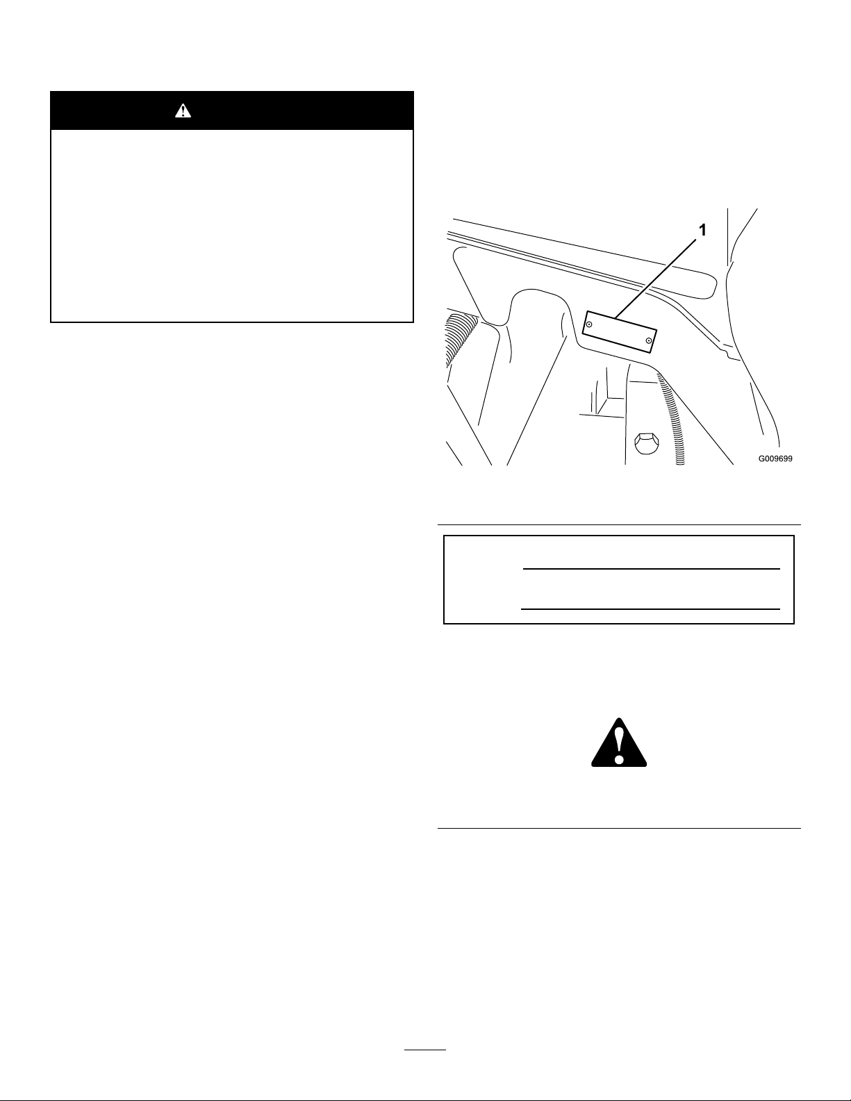
yourproductready.Figure1identiesthelocationofthe
modelandserialnumbersontherightfrontframemember
oftheproduct.Writethenumbersinthespaceprovided.
Figure1
1.Modelandserialnumberlocation
ModelNo.
SerialNo.
Thismanualidentiespotentialhazardsandhassafety
messagesidentiedbythesafetyalertsymbol(Figure2),
whichsignalsahazardthatmaycauseseriousinjuryordeath
ifyoudonotfollowtherecommendedprecautions.
Introduction
Thismachineisaride-on,reel-bladelawnmowerintended
tobeusedbyprofessional,hiredoperatorsincommercial
applications.Itisprimarilydesignedforcuttinggrasson
well-maintainedlawnsingolfcourses,parks,sportselds,
andoncommercialgrounds.Itisnotdesignedforcutting
brush,mowinggrassandothergrowthalongsidehighways,
orforagriculturaluses.
Readthisinformationcarefullytolearnhowtooperateand
maintainyourproductproperlyandtoavoidinjuryand
productdamage.Youareresponsibleforoperatingthe
productproperlyandsafely.
©2014—TheToro®Company
8111LyndaleAvenueSouth
Bloomington,MN55420
Figure2
1.Safetyalertsymbol.
Thismanualusestwootherwordstohighlightinformation.
Importantcallsattentiontospecialmechanicalinformation
andNoteemphasizesgeneralinformationworthyofspecial
attention.
Contactusatwww.Toro.com.
2
PrintedintheUSA.
AllRightsReserved
Page 3

Contents
Safety...........................................................................4
SafeOperatingPractices...........................................4
ToroRidingMowerSafety........................................6
SoundPowerLevel..................................................7
SoundPressureLevel...............................................7
VibrationLevel......................................................7
SafetyandInstructionalDecals.................................7
Setup...........................................................................13
1AdjustingtheSupportRollers................................14
2ReplacingtheWarningDecalforCE
Compliance........................................................14
3InstallingtheHoodLockforCE
Compliance........................................................14
4InstallingtheCuttingUnits....................................15
5AdjustingtheTurfCompensationSpring.................19
6UsingtheCuttingUnitKickstand...........................19
7GreasingtheMachine...........................................20
8CheckingFluidLevels...........................................21
9UsingtheGaugeBar............................................21
ProductOverview.........................................................22
Controls...............................................................22
Specications........................................................28
TractionUnitSpecications.....................................28
Attachments/Accessories........................................28
Operation....................................................................29
CheckingtheEngineOilLevel.................................29
CheckingtheCoolingSystem...................................29
FillingtheFuelTank...............................................30
CheckingtheHydraulicFluidLevel...........................31
CheckingtheTirePressure......................................32
StartingandStoppingtheEngine..............................32
EngineSpeedSwitch...............................................32
CheckingtheInterlockSwitches...............................32
AdjustingtheLiftArmCounterbalance.....................33
AdjustingtheLiftArmTurnAroundPosition.............33
PushingorTowingtheMachine................................34
JackingPoints........................................................34
TieDowns............................................................34
OperatingCharacteristics........................................34
OperatingTips......................................................35
Maintenance.................................................................36
RecommendedMaintenanceSchedule(s)......................36
DailyMaintenanceChecklist....................................37
ServiceIntervalChart.............................................38
PremaintenanceProcedures........................................39
RemovingtheHood...............................................39
Lubrication...............................................................39
GreasingtheBearingsandBushings..........................39
EngineMaintenance..................................................41
ServicingtheAirCleaner.........................................41
ServicingtheEngineOilandFilter............................42
ServicingtheDieselParticulateFilter(DPF)...............42
ServicingtheDieselOxidationCatalyst
(DOC)..............................................................42
FuelSystemMaintenance...........................................43
FuelTank..............................................................43
FuelLinesandConnections.....................................43
ServicingtheWaterSeparator..................................43
ServicingtheFuelFilter...........................................43
FuelPickupTubeScreen.........................................44
ElectricalSystemMaintenance....................................44
ChargingandConnectingtheBattery........................44
BatteryCare...........................................................45
Fuses....................................................................46
DriveSystemMaintenance.........................................47
CheckingtheTorqueoftheWheelNuts.....................47
CheckingthePlanetaryGearDriveOil......................47
ChangingthePlanetaryGearDriveOil......................47
CheckingtheRearAxleLubricant.............................48
ChangingtheRearAxleLubricant.............................48
AdjustingtheTractionDriveforNeutral....................48
CheckingtheRearWheelToe-In..............................49
CoolingSystemMaintenance......................................50
ServicingtheEngineCoolingSystem........................50
BrakeMaintenance....................................................51
AdjustingtheServiceBrakes....................................51
BeltMaintenance......................................................51
ServicingtheAlternatorBelt....................................51
HydraulicSystemMaintenance....................................52
ChangingtheHydraulicFluid...................................52
ReplacingtheHydraulicFilters.................................52
CheckingtheHydraulicLinesandHoses....................52
CuttingUnitMaintenance...........................................53
BacklappingtheCuttingUnits..................................53
Storage........................................................................54
Engine..................................................................54
TractionUnit.........................................................54
3
Page 4

Safety
ThismachinemeetsorexceedsENISO5395:2013
(whenappropriatedecalsapplied),andANSIB71.4-2012
specicationsineffectatthetimeofproduction.
Improperuseormaintenancebytheoperatororownercan
resultininjury.Toreducethepotentialforinjury,comply
withthesesafetyinstructionsandalwayspayattentiontothe
safetyalertsymbol,whichmeansCAUTION,WARNING,or
DANGER-"personalsafetyinstruction."Failuretocomply
withtheinstructionmayresultinpersonalinjuryordeath.
SafeOperatingPractices
ThefollowinginstructionsarefromtheENISO5395:2013
andANSIB71.4-2012.
hair,looseclothing,orjewelrymaygettangledinmoving
parts.Donotoperatetheequipmentwhenbarefootor
wearingopensandals.
•Thoroughlyinspecttheareawheretheequipmentisto
beusedandremoveallobjectswhichmaybethrownby
themachine.
•Replacefaultysilencers/mufers.
•Evaluatetheterraintodeterminewhataccessoriesand
attachmentsareneededtoproperlyandsafelyperform
thejob.Onlyuseaccessoriesandattachmentsapproved
bythemanufacturer.
•Checkthattheoperator'spresencecontrols,safety
switchesandshieldsareattachedandfunctioning
properly.Donotoperateunlesstheyarefunctioning
properly.
Training
•Readtheoperator'smanualandothertrainingmaterial
carefully.Befamiliarwiththecontrols,safetysigns,and
theproperuseoftheequipment.
•Neverallowchildrenorpeopleunfamiliarwiththese
instructionstouseorservicethemower.Local
regulationsmayrestricttheageoftheoperator.
•Nevermowwhilepeople,especiallychildren,orpetsare
nearby.
•Keepinmindthattheoperatororuserisresponsiblefor
accidentsorhazardsoccurringtootherpeopleortheir
property.
•Donotcarrypassengers.
•Alldriversandmechanicsshouldseekandobtain
professionalandpracticalinstruction.Theowneris
responsiblefortrainingtheusers.Suchinstructionshould
emphasize:
–theneedforcareandconcentrationwhenworking
withride-onmachines;
–controlofaride-onmachineslidingonaslopewill
notberegainedbytheapplicationofthebrake.The
mainreasonsforlossofcontrolare:
◊insufcientwheelgrip;
◊beingdriventoofast;
◊inadequatebraking;
◊thetypeofmachineisunsuitableforitstask;
◊lackofawarenessoftheeffectofground
conditions,especiallyslopes;
◊incorrecthitchingandloaddistribution.
•Theowner/usercanpreventandisresponsiblefor
accidentsorinjuriesoccurringtohimselforherself,other
people,orproperty.
Preparation
•Whilemowing,alwayswearsubstantialfootwear,long
trousers,hardhat,safetyglasses,andearprotection.Long
SafeHandlingofFuels
•Toavoidpersonalinjuryorpropertydamage,use
extremecareinhandlinggasoline.Gasolineisextremely
ammableandthevaporsareexplosive.
•Extinguishallcigarettes,cigars,pipes,andothersources
ofignition.
•Useonlyanapprovedfuelcontainer.
•Neverremovefuelcaporaddfuelwiththeengine
running.
•Allowenginetocoolbeforerefueling.
•Neverrefuelthemachineindoors.
•Neverstorethemachineorfuelcontainerwherethereis
anopename,spark,orpilotlightsuchasonawater
heateroronotherappliances.
•Neverllcontainersinsideavehicleoronatruckor
trailerbedwithaplasticliner.Alwaysplacecontainerson
thegroundawayfromyourvehiclebeforelling.
•Removeequipmentfromthetruckortrailerandrefuelit
ontheground.Ifthisisnotpossible,thenrefuelsuch
equipmentwithaportablecontainer,ratherthanfroma
fueldispensernozzle.
•Keepthenozzleincontactwiththerimofthefueltank
orcontaineropeningatalltimesuntilfuelingiscomplete.
Donotuseanozzlelockopendevice.
•Iffuelisspilledonclothing,changeclothingimmediately.
•Neveroverllfueltank.Replacefuelcapandtighten
securely.
Operation
•Donotoperatetheengineinaconnedspacewhere
dangerouscarbonmonoxidefumescancollect.
•Mowonlyindaylightoringoodarticiallight.
•Beforeattemptingtostarttheengine,disengageallblade
attachmentclutches,shiftintoneutral,andengagethe
parkingbrake.
4
Page 5

•Rememberthereisnosuchthingasasafeslope.Travel
ongrassslopesrequiresparticularcare.T oguardagainst
overturning:
–donotstoporstartsuddenlywhengoingupor
downhill;
–machinespeedsshouldbekeptlowonslopesand
duringtightturns;
–stayalertforhumpsandhollowsandotherhidden
hazards;
–Donotturnsharply.Usecarewhenreversing.
–Usecounterweight(s)orwheelweightswhen
suggestedintheoperator'smanual.
•Stayalertforholesintheterrainandotherhiddenhazards.
•Watchoutfortrafcwhencrossingornearroadways.
•Stopthebladesrotatingbeforecrossingsurfacesother
thangrass.
•Whenusinganyattachments,neverdirectdischargeof
materialtowardbystandersnorallowanyonenearthe
machinewhileinoperation.
•Neveroperatethemachinewithdamagedguards,shields,
orwithoutsafetyprotectivedevicesinplace.Besureall
interlocksareattached,adjustedproperly ,andfunctioning
properly.
•Donotchangetheenginegovernorsettingsorover-speed
theengine.Operatingtheengineatexcessivespeedmay
increasethehazardofpersonalinjury.
•Beforeleavingtheoperator'sposition:
–stoponlevelground;
–disengagethepowertake-offandlowerthe
attachments;
–changeintoneutralandsettheparkingbrake;
–stoptheengineandremovethekey.
•Disengagedrivetoattachmentswhentransportingornot
inuse.
•Stoptheengineanddisengagedrivetoattachment:
–beforerefuelling;
–beforemakingheightadjustmentunlessadjustment
canbemadefromtheoperator'sposition.
–beforeclearingblockages;
–beforechecking,cleaningorworkingonthemower;
–afterstrikingaforeignobjectorifanabnormal
vibrationoccurs.Inspectthemowerfordamage
andmakerepairsbeforerestartingandoperatingthe
equipment.
•Reducethethrottlesettingduringenginerun-outand,if
theengineisprovidedwithashut-offvalve,turnthefuel
offattheconclusionofmowing.
•Keephandsandfeetawayfromthecuttingunits.
•Lookbehindanddownbeforebackinguptobesureof
aclearpath.
•Slowdownandusecautionwhenmakingturnsand
crossingroadsandsidewalks.Stopcylinders/reelsifnot
mowing.
•Donotoperatethemowerundertheinuenceofalcohol
ordrugs.
•Lightningcancausesevereinjuryordeath.Iflightning
isseenorthunderisheardinthearea,donotoperate
themachine;seekshelter.
•Usecarewhenloadingorunloadingthemachineintoa
trailerortruck.
•Usecarewhenapproachingblindcorners,shrubs,trees,
orotherobjectsthatmayobscurevision.
MaintenanceandStorage
•Keepallnuts,boltsandscrewstighttobesurethe
equipmentisinsafeworkingcondition.
•Neverstoretheequipmentwithfuelinthetankinsidea
buildingwherefumesmayreachanopenameorspark.
•Allowtheenginetocoolbeforestoringinanyenclosure.
•Toreducetherehazard,keeptheengine,
silencer/mufer,batterycompartmentandfuelstorage
areafreeofgrass,leaves,orexcessivegrease.
•Keepallpartsingoodworkingconditionandallhardware
andhydraulicttingstightened.Replaceallwornor
damagedpartsanddecals.
•Ifthefueltankhastobedrained,dothisoutdoors.
•Becarefulduringadjustmentofthemachinetoprevent
entrapmentofthengersbetweenmovingbladesand
xedpartsofthemachine.
•Onmulti-cylinder/multi-reelmachines,takecareas
rotatingonecylinder/reelcancauseothercylinders/reels
torotate.
•Disengagedrives,lowerthecuttingunits,setparking
brake,stopengineandremovekeyfromignition.Wait
forallmovementtostopbeforeadjusting,cleaningor
repairing.
•Cleangrassanddebrisfromcuttingunits,drives,
silencers/mufers,andenginetohelppreventres.Clean
upoilorfuelspillage.
•Usejackstandstosupportcomponentswhenrequired.
•Carefullyreleasepressurefromcomponentswithstored
energy.
•Disconnectbatterybeforemakinganyrepairs.Disconnect
thenegativeterminalrstandthepositivelast.Reconnect
positiverstandnegativelast.
•Usecarewhencheckingthecylinders/reels.Weargloves
andusecautionwhenservicingthem.
•Keephandsandfeetawayfrommovingparts.Ifpossible,
donotmakeadjustmentswiththeenginerunning.
•Chargebatteriesinanopenwellventilatedarea,away
fromsparkandames.Unplugchargerbeforeconnecting
5
Page 6

ordisconnectingfrombattery.W earprotectiveclothing
anduseinsulatedtools.
Hauling
•Usecarewhenloadingorunloadingthemachineintoa
trailerortruck.
•Usefullwidthrampsforloadingmachineintotraileror
truck.
•Tiethemachinedownsecurelyusingstraps,chains,cable,
orropes.Bothfrontandrearstrapsshouldbedirected
downandoutwardfromthemachine
ToroRidingMowerSafety
ThefollowinglistcontainssafetyinformationspecictoToro
productsorothersafetyinformationthatyoumustknowthat
isnotincludedintheCEN,ISO,orANSIstandard.
Thisproductiscapableofamputatinghandsandfeetand
throwingobjects.Alwaysfollowallsafetyinstructionsto
avoidseriousinjuryordeath.
Useofthisproductforpurposesotherthanitsintendeduse
couldprovedangeroustouserandbystanders.
WARNING
Engineexhaustcontainscarbonmonoxide,which
isanodorless,deadlypoisonthatcankillyou.
Donotrunengineindoorsorinanenclosedarea.
•Knowhowtostoptheenginequickly.
•Donotoperatethemachinewhilewearingtennisshoes
orsneakers.
•Wearingsafetyshoesandlongpantsisadvisableand
requiredbysomelocalordinancesandinsurance
regulations.
•Handlefuelcarefully.Wipeupanyspills.
•Checkthesafetyinterlockswitchesdailyforproper
operation.Ifaswitchshouldfail,replacetheswitch
beforeoperatingthemachine.
•Beforestartingtheengine,sitontheseat.
•Usingthemachinedemandsattention.Topreventloss
ofcontrol:
–Donotdriveclosetosandtraps,ditches,creeks,
embankments,orotherhazards.
–Reducespeedwhenmakingsharpturns.Avoid
suddenstopsandstarts.
–Whennearorcrossingroads,alwaysyieldthe
right-of-way.
–Applytheservicebrakeswhengoingdownhillto
keepforwardspeedslowandtomaintaincontrolof
themachine.
•WhenoperatingamachinewithROPS(roll-over
protectionsystem)neverremovetheROPSandalways
usetheseatbelt.
•Raisethecuttingunitswhendrivingfromoneworkarea
toanother.
•Donottouchtheengine,silencer/mufer,orexhaust
pipewhiletheengineisrunningorsoonafterithas
stoppedbecausetheseareascouldbehotenoughtocause
burns.
•Onanyhill,thereisthepossibilityoftippingorrolling
over,buttheriskincreasesastheslopeangleincreases.
Steephillsshouldbeavoided.
Cuttingunitsmustbeloweredwhengoingdownslopes
tomaintainsteeringcontrol
•Engagetractiondriveslowly,alwayskeepfootontraction
pedal,especiallywhentravelingdownhill.
Usereverseontractionpedalforbraking.
•Ifthemachinestallswhenclimbingaslope,donotturn
themachinearound.Alwaysbackslowly,straightdown
theslope.
•Whenapersonorpetappearsunexpectedlyinornearthe
mowingarea,stopmowing.Carelessoperation,combined
withterrainangles,ricochets,orimproperlypositioned
guardscanleadtothrownobjectinjuries.Donotresume
mowinguntiltheareaiscleared.
MaintenanceandStorage
•Makesureallhydrauliclineconnectorsaretightandall
hydraulichosesandlinesareingoodconditionbefore
applyingpressuretothesystem.
•Keepyourbodyandhandsawayfrompinholeleaksor
nozzlesthatejecthydraulicuidunderhighpressure.
Usepaperorcardboard,notyourhands,tosearchfor
leaks.Hydraulicuidescapingunderpressurecanhave
sufcientforcetopenetratetheskinandcauseserious
injury.Seekimmediatemedicalattentionifuidis
injectedintoskin.
•Beforedisconnectingorperforminganyworkonthe
hydraulicsystem,allpressureinthesystemmustbe
relievedbystoppingtheengineandloweringthecutting
unitsandattachmentstotheground.
•Checkallfuellinesfortightnessandwearonaregular
basis.Tightenorrepairthemasneeded.
•Iftheenginemustberunningtoperformamaintenance
adjustment,keephands,feet,clothing,andanypartsof
thebodyawayfromthecuttingunits,attachments,and
anymovingparts.
•Toensuresafetyandaccuracy,haveanAuthorizedToro
Distributorcheckthemaximumenginespeedwitha
tachometer.
•Ifmajorrepairsareeverneededorifassistanceisdesired,
contactanAuthorizedToroDistributor.
•UseonlyToro-approvedattachmentsandreplacement
parts.Thewarrantymaybevoidedifusedwith
unapprovedattachments.
6
Page 7
SoundPowerLevel
VibrationLevel
Thisunithasaguaranteedsoundpowerlevelof101dBA,
whichincludesanUncertaintyValue(K)of1dBA.
Soundpowerlevelwasdeterminedaccordingtothe
proceduresoutlinedinISO11094.
SoundPressureLevel
Thisunithasasoundpressurelevelattheoperator’searof83
dBA,whichincludesanUncertaintyValue(K)of1dBA.
Soundpressurelevelwasdeterminedaccordingtothe
proceduresoutlinedinENISO5395:2013.
SafetyandInstructionalDecals
Safetydecalsandinstructionsareeasilyvisibletotheoperatorandarelocatednearanyareaofpotential
danger.Replaceanydecalthatisdamagedorlost.
Hand-Arm
Measuredvibrationlevelforrighthand=0.3m/s
Measuredvibrationlevelforlefthand=0.3m/s
UncertaintyValue(K)=0.16m/s
2
Measuredvaluesweredeterminedaccordingtotheprocedures
outlinedinENISO5395:2013.
WholeBody
Measuredvibrationlevel=0.2m/s
UncertaintyValue(K)=0.1m/s
2
2
Measuredvaluesweredeterminedaccordingtotheprocedures
outlinedinENISO5395:2013.
2
2
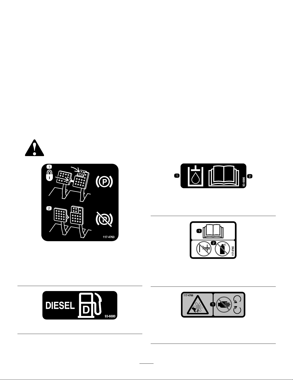
1.Toengagetheparking
brake,securethebrake
pedalswiththelockingpin,
presstheparkingbrake
pedalsandengagethetoe
pedal.
117-4763
93-6680
2.Todisengagetheparking
brake,disengagethe
lockingpinandreleasethe
pedals.
93-6686
1.Hydraulicoil
2.ReadtheOperator'sManual.
117-4765
1.ReadtheOperator'sManual.
2.Donotusestartingaids.
117-4766
1.Cutting/dismembermenthazard;fan—stayawayfrom
movingparts.
7
Page 8
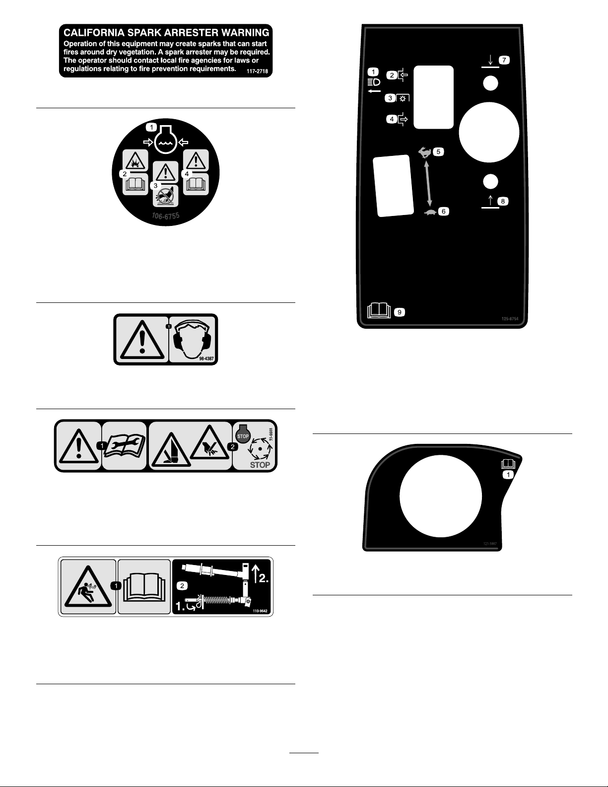
117–2718
106-6755
1.Enginecoolantunder
pressure.
2.Explosionhazard—read
theOperator'sManual.
1.Warning—wearhearingprotection.
1.Warning—readthe
instructionsbefore
servicingorperforming
maintenance.
3.Warning—donottouchthe
hotsurface.
4.Warning—readthe
Operator'sManual.
98-4387
93-6688
2.Cuttinghazardofhandor
foot—stoptheengineand
waitformovingpartsto
stop.
125–8754
1.Headlights
2.Engage7.Lowerthecuttingunits
3.Powertake-off(PTO)
4.Disengage
5.Fast
6.Slow
8.Raisethecuttingunits
9.ReadtheOperator’s
Manual.
110-9642
1.Storedenergyhazard—readtheOperator'sManual.
2.Movethecotterpintotheholeclosesttotherodbracket
andthenremovetheliftarmandpivotyoke.
121–3887
1.ReadtheOperator’sManual.
8
Page 9
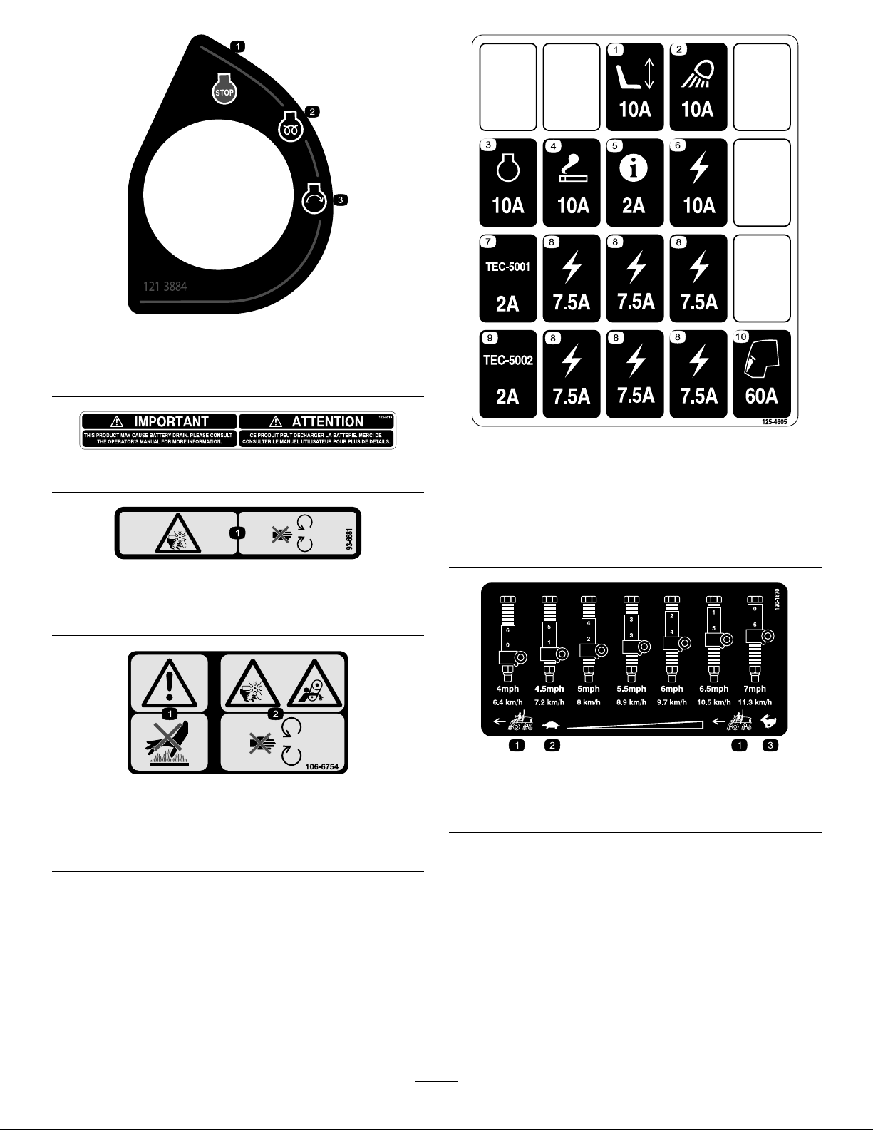
121–3884
1.Engine—stop3.Engine—start
2.Engine—preheat
112-5019
93–6681
1.Cutting/dismembermenthazard—stayawayfrommoving
parts.
125–4605
1.Powerseat,10A6.Powersupplied,10A
2.Worklight,10A
3.Engine,10A8.Powersupplied,7.5A
4.Cigarettelighter,10A9.Controller,2A
5.Infocenter,2A
7.Controller,2A
10.Enginepreheat,60A
106-6754
1.Warning—donottouchthehotsurface.
2.Cutting/dismembermenthazard,fanandentanglement
hazard,belt—stayawayfrommovingparts.
120-1670
1.Tractionunitspeed3.Fast
2.Slow
9
Page 10
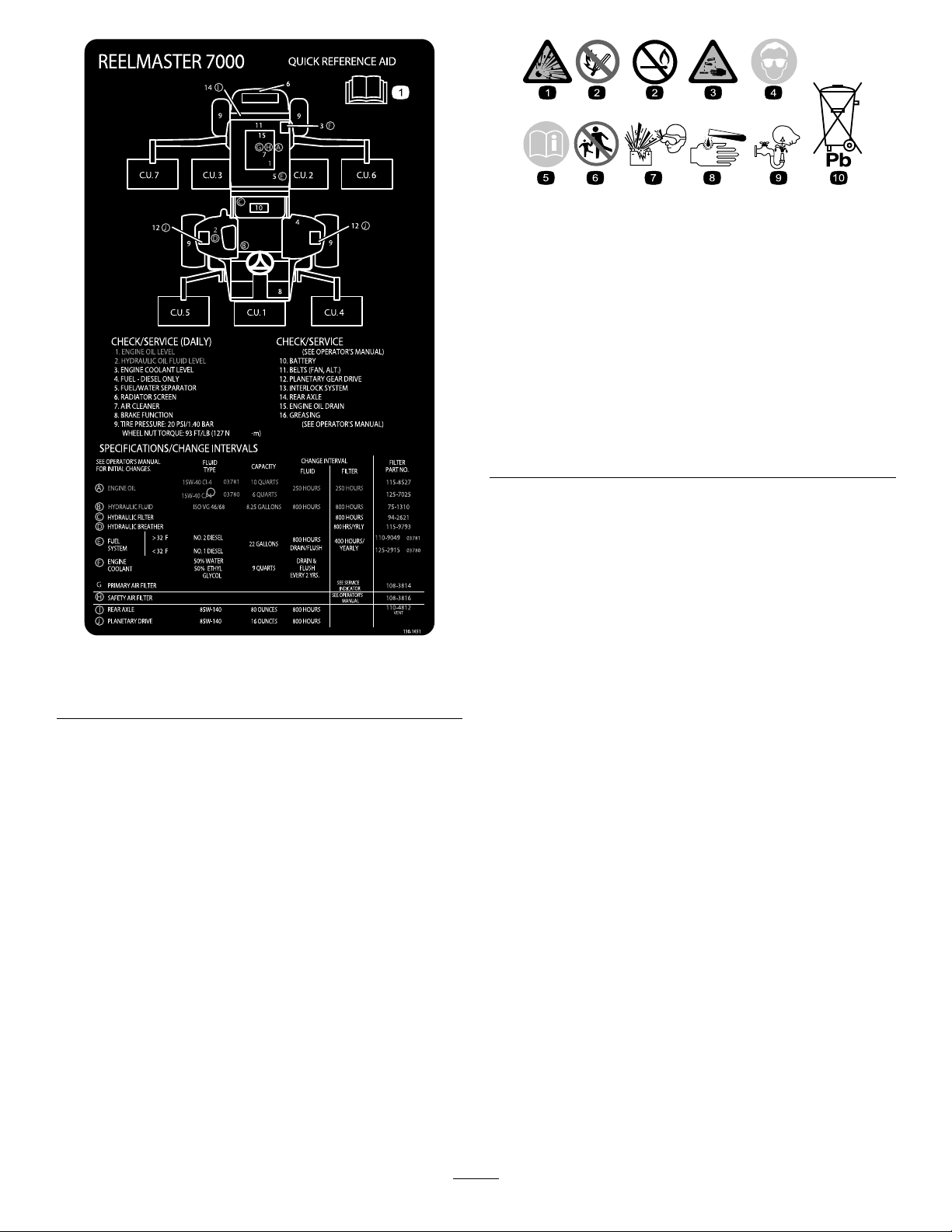
BatterySymbols
Someorallofthesesymbolsareonyourbattery
130-1651
1.ReadtheOperator'sManualformoreinformationof
servicingthemachine.
1.Explosionhazard
2.Nore,opename,or
smoking.
3.Causticliquid/chemical
burnhazard
4.Weareyeprotection9.Flusheyesimmediately
5.ReadtheOperator's
Manual.
6.Keepbystandersasafe
7.Weareyeprotection;
8.Batteryacidcancause
10.Containslead;donot
distancefromthebattery.
explosivegasescan
causeblindnessandother
injuries
blindnessorsevereburns.
withwaterandgetmedical
helpfast.
discard.
10
Page 11
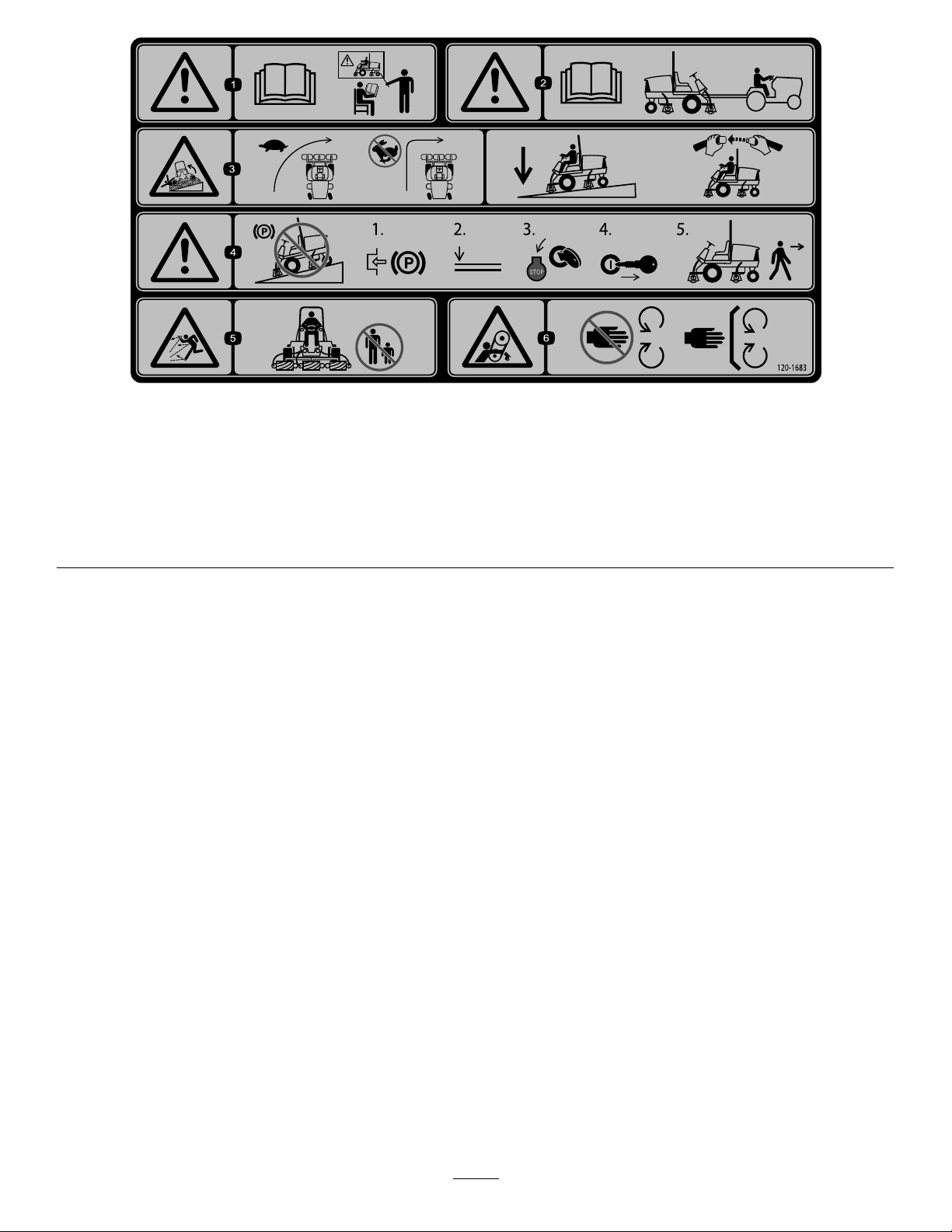
120-1683
1.Warning—readtheOperator'sManual,donotoperatethis
machineunlessyouaretrained.
2.Warning—readtheOperator'sManualbeforetowingthe
machine.
3.Tippinghazard—slowmachinebeforeturning,donotturnat
highspeeds;lowerthecuttingunitwhendrivingdownslopes;
usearolloverprotectionsystemandweartheseatbelt
4.Warning—donotparkthemachineonslopes;engagethe
parkingbrake,lowerthecuttingunits,stoptheengineand
removetheignitionkeybeforeleavingthemachine.
5.Thrownobjecthazard—keepbystandersasafedistancefrom
themachine.
6.Entanglementhazard,belt—stayawayfrommovingparts,
keepallguardsandshieldsinplace.
11
Page 12
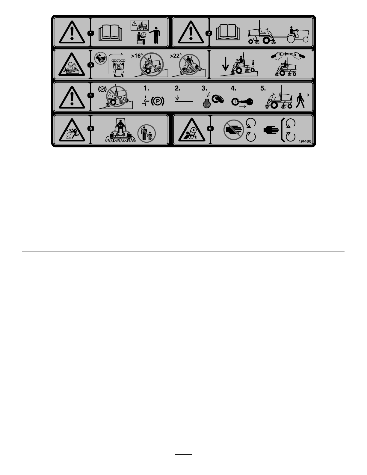
120-1686
Afxoverpartno.120–1683forCE*
*ThissafetydecalincludesaslopewarningrequiredonthemachinefrocompliancetotheEuropeanLawnMowerStandardENISO5395:2013.Theconservativemaximumslope
anglesindicatedforoperationofthismachineareprescribedbyandrequiredbythisstandard.
1.Warning—readtheOperator'sManual,donotoperatethis
machineunlessyouaretrained.
2.Warning—readtheOperator'sManualbeforetowingthe
machine.
3.Tippinghazard—donotturnathighspeeds,donotupand
downslopesgreaterthan16degrees,donotmowacross
slopesgreaterthan22degrees;lowerthecuttingunitwhen
drivingdownslopes;usearolloverprotectionsystemand
weartheseatbelt
4.Warning—donotparkthemachineonslopes;engagethe
parkingbrake,lowerthecuttingunits,stoptheengineand
removetheignitionkeybeforeleavingthemachine.
5.Thrownobjecthazard—keepbystandersasafedistancefrom
themachine.
6.Entanglementhazard,belt—stayawayfrommovingparts,
keepallguardsandshieldsinplace.
12
Page 13

Setup
LooseParts
Usethechartbelowtoverifythatallpartshavebeenshipped.
ProcedureDescription
1
2
3
4
5
6
7
8
9
Nopartsrequired
Warningdecal1
Hoodlockbracket1
Rivet2
Screw,1/4x2inch
Flatwasher,1/4inch
Locknut,1/4inch
Fronthoseguide-R.H.1
Fronthoseguide-L.H.1
Nopartsrequired
Cuttingunitkickstand
Nopartsrequired
Nopartsrequired
Gaugebar
Qty.
Use
–
1
2
1
–
1
–
–
1
Adjustthesupportrollers
UsedonlyonmachinesrequiringCE
Compliance.
Usedonlyonmachinesrequiring
EuropeanCECompliance.
Installthecuttingunits
Adjusttheturfcompensationspring.
InstalltheCuttingUnitKickstand.
Greasethemachine.
Checktherearaxlelubricant,hydraulic
uid,andengineoillevels
Usethegaugebartoadjustthecutting
unit.
MediaandAdditionalParts
Description
Operator'sManual
EngineOperator'sManual
PartsCatalog
OperatorTrainingMaterial
DeclarationofConformity
Note:Determinetheleftandrightsidesofthemachinefromthenormaloperatingposition.
Qty.
1
1
1
1
1
Readbeforeoperatingmachine
Readbeforeoperatingengine
Usetoreferencepartnumbers
Viewbeforeoperatingmachine
UseforCECompliance
Use
13
Page 14
1
g019541
1
2
3
2
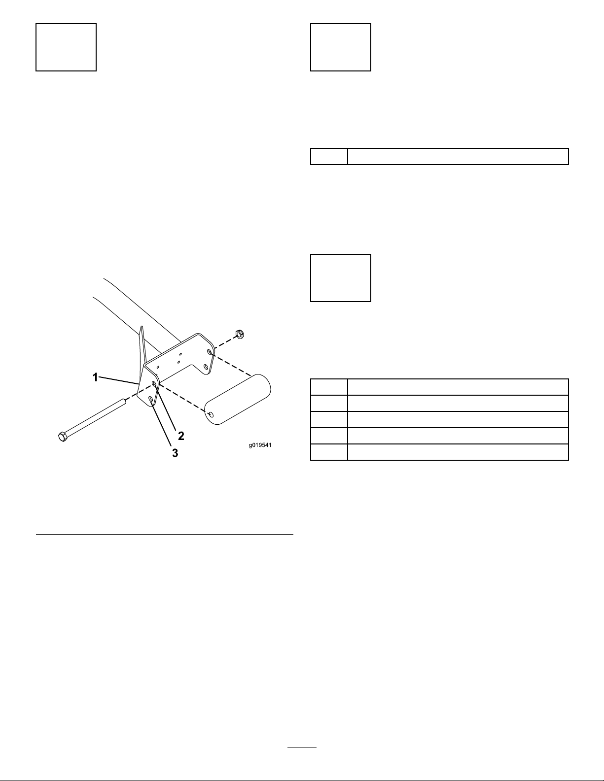
AdjustingtheSupportRollers
NoPartsRequired
Procedure
Dependingonwhatwidthcuttingunitsaretobeinstalledon
thetraction,adjustthesupportrollersasfollows:
•Ifusing27inchcuttingunits,therollersaretobeinstalled
intheuppermountingholesofsupportassembly
channels(Figure3).
•Ifusing32inchcuttingunits,therollersaretobe
installedinthelowermountingholesofsupportassembly
channels(Figure3).
ReplacingtheWarningDecal forCECompliance
Partsneededforthisprocedure:
1Warningdecal
Procedure
OnmachinesrequiringCECompliance,afxthewarning
decal,partno.120–1683overthewarningdecalpartno.
120–1686.
3
InstallingtheHoodLockfor CECompliance
Partsneededforthisprocedure:
Figure3
1.Supportassemblychannel3.Usethisholefor32inch
cuttingunits
2.Usethisholefor27inch
cuttingunits
1Hoodlockbracket
2Rivet
1
Screw,1/4x2inch
2
Flatwasher,1/4inch
1
Locknut,1/4inch
Procedure
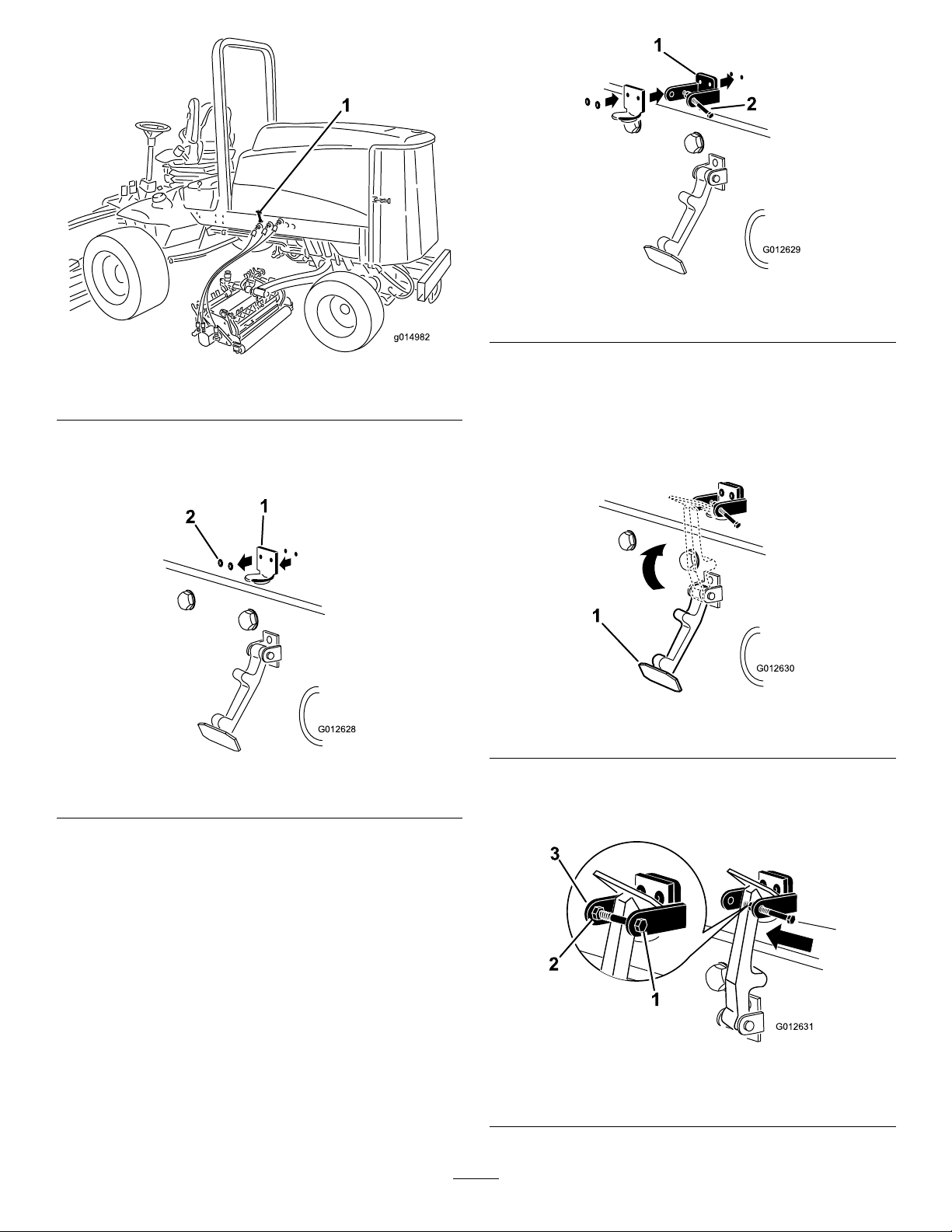
1.Unhookthehoodlatchfromthehoodlatchbracket
(Figure4).
14
Page 15
G012628
1
2
G012629
1
2
Figure6
G012630
1
G012631
1
2
3
Figure4
1.Hoodlatch
2.Removethe(2)rivetssecuringthehoodlatchbracket
tothehood(Figure5).Removethehoodlatchbracket
fromthehood.
Figure5
1.Hoodlatchbracket2.Rivets
3.Whilealigningthemountingholes,positiontheCE
lockbracketandthehoodlatchbracketontothehood.
Thelockbracketmustbeagainstthehood(Figure5).
Donotremoveboltandnutassemblyfromthelock
bracketarm.
1.CElockbracket
2.Boltandnutassembly
4.Alignthewasherswiththeholesontheinsideofthe
hood.
5.Rivetthebracketsandthewasherstothehood(Figure
6).
6.Hookthelatchontothehoodlatchbracket(Figure7).
Figure7
1.Hoodlatch
7.Screwtheboltintotheotherarmofhoodlockbracket
tolockthelatchinposition(Figure8).Tightenbolt
securelybutdonottightennut.
1.Bolt
2.Nut
15
Figure8
3.Armofhoodlockbracket
Page 16
4
InstallingtheCuttingUnits
Partsneededforthisprocedure:
1Fronthoseguide-R.H.
1Fronthoseguide-L.H.
Procedure
1.Removethereelmotorsfromtheshippingbrackets.
2.Removetheshippingbracketsanddiscard.
3.Removethecuttingunitsfromthecartons.Assemble
andadjustasdescribedinthecuttingunitOperator's
Manual.
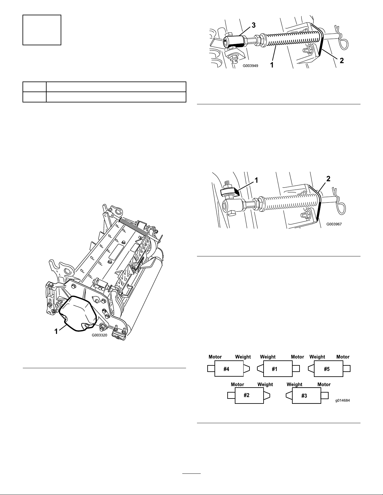
4.Makesurethecounterweight(Figure9)isinstalledto
theproperendofthecuttingunitasdescribedinthe
cuttingunitOperator'sManual.
Figure10
1.Turfcompensationspring3.Springtube
2.Rodbracket
B.Removetheangenutsecuringthespringtube
bolttothecarrierframetab(Figure10)Remove
theassembly.
C.Mountthespringtubebolttotheoppositetabon
thecarrierframeandsecurewiththeangenut.
Theboltheadistobepositionedtotheouterside
ofthetabasshowninFigure11.
Figure11
1.Oppositecarrierframetab
2.Rodbracket
Figure9
1.Counterweight
5.Allthecuttingunitsareshippedwiththeturf
compensationspringmountedtotherightsideofthe
cuttingunit.Theturfcompensationspringmustbe
mountedtothesamesideofthecuttingunitasthe
reeldrivemotor.Repositiontheturfcompensation
asfollows:
A.Removethe2carriageboltsandnutssecuringthe
rodbrackettothecuttingunittabs(Figure10).
D.Mounttherodbrackettothecuttingunittabs
withthecarriageboltsandnuts(Figure11).Also,
onthecuttingunit,mountthelefthandhose
guidetothefrontofthecuttingunittabswhen
reinstallingtherodbracket(Figure13).
Important:Onthe#4(leftfront)and#5
(rightfront)cuttingunits,usetherodbracket
mountingnutstoinstallthehoseguidesto
thefrontofthecuttingunittabs.Thehose
guidesshouldleantowardthecentercutting
unit(Figure12throughFigure14).
Figure12
16
Page 17
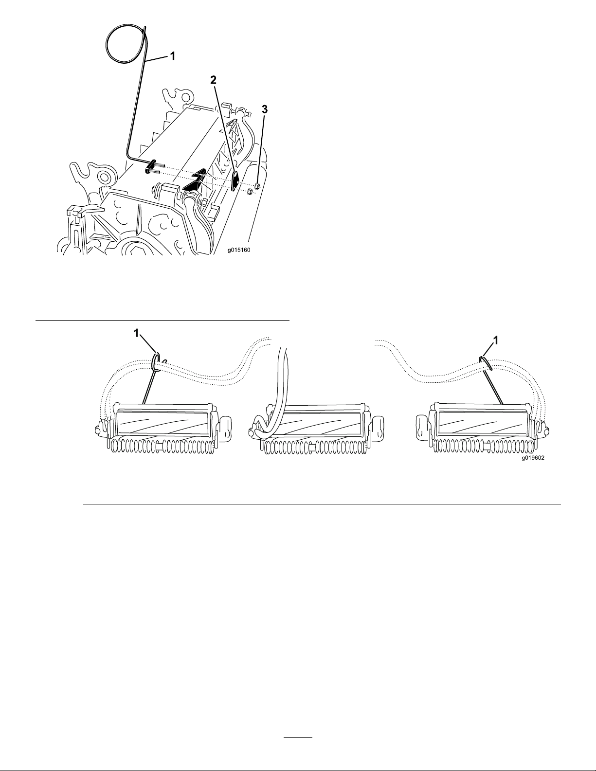
Figure13
g019602
1
1
1.Hoseguide(Lefthand
shown)
2.Rodbracket
1.Hoseguides(eachmustleantowardthecentercuttingunit)
3.Nuts
Note:Wheninstallingorremovingthecutting
units,makesurethehairpincotterisinstalled
inthespringrodholenexttotherodbracket.
Otherwise,thehairpincottermustbeinstalledin
theholeintheendoftherod.
Figure14
6.Increasethesteeringontherearcuttingunitsby
removingthe(2)pivotspacers,hexsocketscrewsand
angelocknuts(Figure15)fromtherear(#2and#3)
cuttingunitcarrierframes(Figure12).
17
Page 18

1
2
3
4
G015978
Figure15
G015976
1
2
3
4
5
1
G015977
9.Forthefrontcuttingunits,slideacuttingunitunder
theliftarmwhileinsertingthecarrierframeshaftup
intotheliftarmpivotyoke(Figure16).Makesurethe
thrustwasherisinpositiononthecarrierframeshaft.
10.Securethecarrierframeshafttotheliftarmyokewith
theKlikpin(Figure16).
11.Tolock(x)thesteeringonthecuttingunits,secure
thepivotyoketothecarrierframewiththesnapper
pin(Figure17).
1.Hexsocketscrew
2.Pivotspacer4.Flangelocknut
3.Carrierframe
7.Loweralltheliftarmscompletely.
8.Coatthecarrierframeshaftwithcleangrease(Figure
16).
Figure17
1.Snapperpin
Note:Fixedsteeringisrecommendedwhen
cuttingsidehills.
12.Usethefollowingprocedureontherearcuttingunits
whentheheightofcutisabove3/4inch.
A.Removethelynchpinandwashersecuringthelift
armpivotshafttotheliftarmandslidethelift
armpivotshaftoutoftheliftarm(Figure18).
1.Liftarmpivotshaftlynchpinandwasher
Figure18
B.Inserttheliftarmyokeontothecarrierframe
Figure16
1.Liftarmpivotyoke4.Carrierframeshaft
2.Liftarm
3.Klikpin
5.Thrustwasher
13.Securetheliftarmchaintothechainbracketwiththe
shaft(Figure16).
C.Inserttheliftarmshaftintotheliftarmandsecure
itwiththewasherandlynchpin(Figure18).
snapperpin(Figure19).Usethenumberofchainlinks
describedinthecuttingunitOperator'sManual.
18
Page 19

Figure19
1.Liftarmchain3.Snapperpin
2.Chainbracket
14.Coatthesplineshaftofthereelmotorwithclean
grease.
15.OilthereelmotorO-ringandinstallitontothemotor
ange.
16.Installthemotorbyrotatingitclockwisesothatthe
motorangesclearthebolts(Figure20).Rotatethe
motorcounterclockwiseuntiltheangesencirclethe
boltsthentightenthebolts.
Important:Makesurethereelmotorhosesare
nottwisted,kinkedorintheriskofbeingpinched.
5
AdjustingtheTurf CompensationSpring
NoPartsRequired
Procedure
Theturfcompensationspring(Figure21)transfersweight
fromthefronttotherearroller.(Thishelpstoreduceawave
patternintheturf,alsoknownasmarcellingorbobbing.)
Important:Makespringadjustmentswiththecutting
unitmountedtothetractionunit,pointingstraight
aheadandloweredtotheshopoor.
1.Makesurethehairpincotterisinstalledintherearhole
inthespringrod(Figure21).
Note:Whenservicingthecuttingunit,movethe
hairpincottertothespringrodholenexttotheturf
compensationspring.
Figure20
1.Reeldrivemotor2.Mountingbolts
Figure21
1.Turfcompensationspring3.Springrod
2.Hairpincotter4.Hexnuts
2.Tightenthehexnutsonthefrontendofthespringrod
untilthecompressedlengthofthespringis6.25inches
(15.9cm)(Figure21).
Note:Whenoperatingonroughterraindecreasethe
springlengthby1/2inch.Groundfollowingwillbe
slightlydecreased.
Note:Theturfcompensationsettingwillneedtobe
resetiftheHOCsettingortheAggressivenessofCut
settingischanged.
19
Page 20

6
UsingtheCuttingUnit
Kickstand
Partsneededforthisprocedure:
1
Cuttingunitkickstand
Procedure
Wheneverthecuttingunithastobetippedtoexposethe
bedknife/reel,propuptherearofthecuttingunitwiththe
kickstandtomakesurethenutsonthebackendofthe
bedbaradjustingscrewsarenotrestingontheworksurface
(Figure22).
Figure23
1.Chainbracket3.Cuttingunitkickstand
2.Snapperpin
Figure22
1.Cuttingunitkickstand
Securethekickstandtothechainbracketwiththesnapper
pin(Figure23).
7
GreasingtheMachine
NoPartsRequired
Procedure
Beforethemachineisoperated,itmustbegreasedtoensure
properlubrication.RefertoLubricationsection.Failureto
properlygreasethemachinewillresultinprematurefailureof
criticalparts.
20
Page 21

8
CheckingFluidLevels
NoPartsRequired
Procedure
1.Checktherearaxlelubricantlevelbeforetheengineis
rststarted,refertoCheckingtheRearAxleLubricant
inDriveSystemMaintenance.
2.Checkthehydraulicuidlevelbeforetheengineisrst
started,refertoCheckingtheHydraulicFluidLevelin
Operation.
3.Checktheengineoillevelbeforeandaftertheengineis
rststarted,refertoCheckingtheEngineOilLevelin
Operation.
9
Figure24
1.Gaugebar4.Holesusedforsetting
GroomerHOG
2.Heightadjustingscrew5.Holenotused
3.Nut
UsingtheGaugeBar
Partsneededforthisprocedure:
1
Gaugebar
Procedure
Usethegaugebartoadjustthecuttingunit.Referto
theCuttingUnitOperator'sManualfortheadjustment
procedures(Figure24).
21
Page 22

ProductOverview
Controls
BrakePedals
Twofootpedals(Figure25)operateindividualwheelbrakes
forturningassistanceandtoaidinobtainingbettersidehill
traction.
PedalLockingLatch
Thepedallockinglatch(Figure25)connectsthepedals
togethertoengagetheparkingbrake.
ParkingBrakePedal
Toengagetheparkingbrake,(Figure25)connectthepedals
togetherwiththepedallockinglatch,pushdownontheright
brakepedalwhileengagingthetoepedal.Toreleasethe
parkingbrake,pressoneofthebrakepedalsuntiltheparking
brakelatchretracts.
MowSpeedLimiter
Whenthemowspeedlimiter(Figure26)isippedupitwill
controlthemowspeedandallowthecuttingunitstobe
engaged.Eachspaceradjuststhemowingspeedby½mile
perhour.Themorespacersyouhave,onthetopofthebolt
thesloweryouwillgo.Fortransport,ipbackthemowspeed
limiterandyouwillhavemaximumtransportspeed.
SpeedLimiterScrews
Adjustthescrew(s)(Figure26)tolimittheamountthe
tractionpedalcanbedepressedintheforwardorreverse
directiontolimitspeed.
Important:Thespeedlimiterscrewmuststopthe
tractionpedalbeforethepumpreachesfullstrokeor
damagetothepumpmayoccur.
Figure25
1.Brakepedal4.Tractionpedal
2.Pedallockinglatch5.Tiltsteeringpedal
3.Parkingbrakepedal
TractionPedal
Thetractionpedal(Figure25)controlsforwardandreverse
operation.Depressthetopofthepedaltomoveforwardand
thebottomtomovebackward.Groundspeeddependson
howfarthepedalisdepressed.Fornoload,maximumground
speed,fullydepressthepedalwhilethethrottleisinFast.
Tostop,reduceyourfootpressureonthetractionpedaland
allowittoreturntothecenterposition.
TiltSteeringPedal
Totiltthesteeringwheeltowardsyou,pressthefootpedal
(Figure25)down,andpullthesteeringtowertowardyouto
themostcomfortablepositionandthenreleasethepedal.
Figure26
1.Reversespeedlimiter
screw
2.Forwardspeedlimiter
screw
3.Spacers
4.Mowspeedlimiter
LowerMow/RaiseControlLever
Thislever(Figure27)raisesandlowersthecuttingunitsand
alsostartsandstopsthecutterheadswhenthecutterheads
areenabledinthemowmode.Thecutterheadscannotbe
loweredwhenthemow/transportleverisinthetransport
position.
KeySwitch
Thekeyswitch(Figure27)hasthreepositions:Off,
On/Preheat,andStart.
InfoCenter
TheInfoCenterLCDdisplayshowsinformationaboutyour
machinesuchastheoperatingstatus,variousdiagnosticsand
otherinformationaboutthemachine(Figure27).
PTOSwitch
ThePTOswitch(Figure27)hastwopositions:Out(start)
andIn(stop).PullthePTObuttonouttoengagethecutting
22
Page 23

unitblades.Pushinthebuttontodisengagethecuttingunit
1
2
3
4
5
6
G021208
blades.
Figure27
1.Lowermow/raisecontrol
lever
2.Keyswitch5.Enginespeedswitch
3.InfoCenter
4.PTOswitch
6.Headlightswitch
EngineSpeedSwitch
Theenginespeedswitch(Figure27)hastwomodesto
changetheenginespeed.Bymomentarilytappingtheswitch,
theenginespeedcanbeincreasedordecreasedin100rpm
increments.Byholdingtheswitchdowntheenginewill
automaticallymovetoHighorLowidle,dependingonwhich
endoftheswitchisdepressed.
HeadlightSwitch
Pivottheswitchdownwardtoturnontheheadlights(Figure
27).
PowerPoint
Thepowerpoint(Figure28)isusedtopoweroptional12
voltelectricalaccessories.
Figure28
1.Powerpoint2.Bagholder
BagHolder
Usethebagholder(Figure28)forstorage.
BacklapLevers
Usethebacklapleversforbacklappingthereels(Figure29).
Figure29
1.Frontbacklaplever2.Rearbacklaplever
23
Page 24

SeatAdjustments
1
g020650
2
3
4
TORO
UsingtheInfoCenterLCDDisplay
ForeandAftAdjustingLever
Pulloutonthelevertoslidetheseatforeoraft(Figure30).
SeatArmRestAdjustingKnob
Rotatetheknobtoadjusttheseatarmrestangle(Figure30).
SeatBackAdjustingLever
Movethelevertoadjusttheseatbackangle(Figure30).
Weightgauge
Indicateswhentheseatisadjustedtotheweightofthe
operator(Figure30).Heightadjustmentismadeby
positioningthesuspensionwithintherangeofthegreen
region.
TheInfoCenterLCDdisplayshowsinformationaboutyour
machinesuchastheoperatingstatus,variousdiagnostics
andotherinformationaboutthemachine(Figure31)There
isasplashscreenandmaininformationscreenofthe
InfoCenter.Youcanswitchbetweenthesplashscreenand
maininformationscreen,atanytime,bypressinganyof
theInfoCenterbuttonsandthenselectingtheappropriate
directionalarrow .
Figure31
1.Indicatorlight3.Middlebutton
2.Rightbutton
4.Leftbutton
•LeftButton,MenuAccess/BackButton—pressthis
buttontoaccesstheInfoCentermenus.Youcanuseitto
backoutofanymenuyouarecurrentlyusing.
•MiddleButton—usethisbuttontoscrolldownmenus.
•RightButton—usethisbuttontoopenamenuwherea
rightarrowindicatesadditionalcontent.
Figure30
1.Weightgauge
2.Weightadjustinglever5.Armrestadjustingknob
3.ForeandAftadjusting
lever
WeightAdjustingLever
4.Seatbackadjustinglever
Adjustforoperatorweight(Figure30).Pulluponthelever
toincreasetheairpressureandpushdowntodecreasetheair
pressure.Theproperadjustmentisattainedwhentheweight
gaugeisinthegreenregion.
•ManualFanReversal—activatedbypressingtheleftand
rightbuttonssimultaneously.
•Beeper—activatedwhenloweringthedecksorfor
advisoriesandfaults.
Note:Thepurposeofeachbuttonmaychange
dependingonwhatisrequiredatthetime.Eachbutton
willbelabeledwithanicondisplayingitscurrentfunction.
24
Page 25

InfoCenterIconDescription
InfoCenterIconDescription(cont'd.)
SERVICEDUE
Indicateswhenscheduledservice
shouldbeperformed
EngineRPM/status—indicatesthe
engineRPM
Infoicon
Fast
Slow
FanReversal—indicateswhenthe
fanisreversed
Stationaryregenerationrequired
Airintakeheaterisactive
Stoporshutdown
Engine
Keyswitch
Indicateswhenthecuttingunitsare
beinglowered
Indicateswhenthecuttingunitsare
beingraised
PINpasscode
HydraulicOilT emperature-indicates
thehydraulicoiltemperature
CANbus
InfoCenter
Badorfailed
Raisecuttingunits
Lowercuttingunits
Operatormustsitinseat
ParkingBrakeIndicator—indicates
whentheparkingbrakeisOn
IdentiestherangeasHigh
Neutral
IdentiestherangeasLow
CoolantTemperature-indicatesthe
enginecoolanttemperatureineither
°Cor°F
Temperature(hot)
Deniedornotallowed
Bulb
OutputofTECcontrollerorcontrol
wireinharness
High:overallowedrange
Low:underallowedrange
Outofrange
/
Switch
Operatormustreleaseswitch
Operatorshouldchangetoindicated
state
Symbolsareoften
combinedtoform
sentences.Some
examplesareshown
below
Operatorshouldputmachinein
neutral
PTOisengaged
EngineStart
Enginestartdenied
Engineshutdown
Enginecoolanttoohot
25
Page 26

InfoCenterIconDescription(cont'd.)
Hydraulicoiltoohot
DPFashaccumulationnotication.
RefertoServicingtheDiesel
ParticulateFilter(DPF)inthe
maintenancesectionfordetails.
Sitdownorsetparkingbrake
UsingtheMenus
ToaccesstheInfoCentermenusystem,pressthemenuaccess
buttonwhileatthemainscreen.Thiswillbringyoutothe
mainmenu.Refertothefollowingtablesforasynopsisof
theoptionsavailablefromthemenus:
MainMenu
MenuItemDescription
FaultsTheFaultsmenucontains
alistoftherecentmachine
faults.RefertotheService
ManualoryourAuthorized
ToroDistributorformore
informationontheFaults
menuandtheinformation
containedthere.
ServiceTheServicemenucontains
informationonthemachine
suchashoursofusecounters
andothersimilarnumbers.
DiagnosticsTheDiagnosticsmenu
displaysthestateofeach
machineswitch,sensorand
controloutput.Y oucanuse
thistotroubleshootcertain
issuesasitwillquicklytellyou
whichmachinecontrolsareon
andwhichareoff.
SettingsTheSettingsmenuallows
youtocustomizeandmodify
congurationvariablesonthe
InfoCenterdisplay.
AboutTheAboutmenuliststhe
modelnumber,serialnumber,
andsoftwareversionofyour
machine.
Service
MenuItemDescription
Hours
Counts
Diagnostics
MenuItemDescription
CuttingUnitsIndicatestheinputs,qualiers
Hi/LowRangeIndicatestheinputs,qualiers
PTOIndicatestheinputs,qualiers
EngineRun
Backlap
Settings
MenuItemDescription
Units
Language
LCDBacklightControlsthebrightnessofthe
LCDContrastControlsthecontrastofthe
FrontBacklapReelSpeedControlsthespeedofthefront
RearBacklapReelSpeedControlsthespeedoftherear
ProtectedMenusAllowsthe
AutoIdle
BladeCountControlsthenumberofblades
MowSpeedControlsthegroundspeedfor
Heightofcut(HOC)Controlstheheightofcut
Liststhetotalnumberofhours
thatthemachine,engineand
PTOhavebeenon,aswell
asthenumberofhoursthe
machinehasbeentransported
andservicedue.
Listsnumerouscountsthe
machinehasexperienced.
andoutputsforraisingand
loweringthecuttingunits.
andoutputsfordrivingin
transportmode.
andoutputsforenablingthe
PTOcircuit.
Indicatestheinputs,qualiers
andoutputsforstartingthe
engine.
Indicatestheinputs,qualiers
andoutputsforoperatingthe
backlapfunction.
Controlstheunitsusedonthe
InfoCenter.Themenuchoices
areEnglishorMetric
Controlsthelanguageused
ontheInfoCenter*.
LCDdisplay.
LCDdisplay.
reelsinbacklapmode.
reelsinbacklapmode.
superintendant/mechanic
toaccessprotectedmenusby
inputtingapasscode.
Controlstheamountoftime
allowedbeforereturningthe
enginetolowidlewhenthe
machineisstationary.
onthereelforreelspeed.
determiningthereelspeed.
(HOC)fordeterminingthereel
speed.
26
Page 27

FReelRPMDisplaysthecalculatedreel
RReelRPMDisplaysthecalculatedreel
speedpositionforthefront
reels.Thereelscanalsobe
manuallyadjusted.
speedpositionfortherear
reels.Thereelscanalsobe
manuallyadjusted.
*Only"operator-faced"textistranslated.Faults,Service,and
Diagnosticsscreensare"service-faced".Titleswillbeinthe
selectedlanguage,butmenuitemsareinEnglish.
About
MenuItemDescription
Model
SNListstheserialnumberofthe
MachineControllerRevisionListsthesoftwarerevisionof
InfoCenterRevisionListsthesoftwarerevisionof
CANBus
Liststhemodelnumberofthe
machine.
machine.
themastercontroller .
theInfoCenter.
Liststhemachine
communicationbusstatus.
TheabilitytoviewandchangethesettingsintheProtected
Menucanbechanged.OncetheProtectedMenuhasbeen
accessed,scrolldowntoProtectSettings.Usingtheright
button,changingProtectSettingstoOFFwillallowthe
abilitytoviewandchangethesettingsintheProtectedMenu
withoutenteringthepasscode.ChangingProtectSettingsto
ONwillhidetheprotectedoptionsandwillrequireenteringa
passcodetochangethesettingintheProtectedMenu.After
thepasscodehasbeenset,thekeyswitchmustbeturnedoff
andbackontoenableandsavethisfeature.
Note:Ifthepasscodehasbeenforgottenormisplaced,
pleasecontactyourdistributorforassistance.
ToSettheAutoIdle
•IntheSettingsMenu,scrolldowntoAutoIdle.
•Presstherightbuttontochangetheautoidletime
betweenOFF,8S,10S,15S,20S,&30S.
ToSettheBladeCount
•IntheSettingsMenu,scrolldowntoBladeCount
•Presstherightbuttontochangethebladecountbetween
5,8or11bladereels.
ProtectedMenus
Thereare8operatingcongurationsettingsthatareadjustable
withintheSettingsMenuoftheInfoCenter:autoidletime
delay,BladeCount,MowSpeed,HeightofCut(HOC),F
ReelRPMandRReelRPM.Thesesettingscanbelocked
byusingtheProtectedMenu.
Note:Atthetimeofdelivery,theinitialpasswordcodeis
programmedbyyourdistributor.
AccessingtheProtectedMenuSettings
ToaccesstheProtectedMenuSettings
•FromtheMainMenu,scrolldowntotheSettingsMenu
andpresstherightbutton.
•IntheSettingsMenu,scrolldowntotheProtectedMenu
andpresstherightbutton.
•Toenterthepasscode,usethecenterbuttontosetthe
rstdigitthenpresstherightbuttontomoveontothe
nextdigit.
•Usethecenterbuttontosettheseconddigitthenpress
therightbuttontomoveontothenextdigit.
•Usethecenterbuttontosetthethirddigitthenpressthe
rightbuttontomoveontothenextdigit.
•Usethecenterbuttontosetthefourthdigitthenpress
therightbutton.
•Pressthemiddlebuttontoenterthecode.
•Ifthecodehasbeenacceptedandtheprotectedmenuhas
been“Unlocked”,“PIN”willbedisplayedintheupper
rightcornerofthedisplayscreen.
ToSettheMowSpeed
•IntheSettingsMenu,scrolldowntoMowSpeed.
•Presstherightbuttontoselectmowspeed.
•Usethecenterandrightbuttontoselecttheappropriate
mowspeedsetonthemechanicalmowspeedlimiteron
thetractionpedal.
•Presstheleftbuttontoexitmowspeedandsavethe
setting.
ToSettheHeightofCut(HOC)
•IntheSettingsMenu,scrolldowntoHOC.
•PresstherightbuttontoselectHOC.
•Usethecenterandrightbuttontoselecttheappropriate
HOCsetting.(Iftheexactsettingisnotdisplayed,select
thenearestHOCsettingfromthelistdisplayed).
•PresstheleftbuttontoexitHOCandsavethesetting.
27
Page 28

ToSettheFrontandRearReelSpeeds
Specications
Althoughthefrontandrearreelspeedsarecalculatedby
inputtingthenumberofblades,mowspeedandHOCinto
theInfoCenter,thesettingcanbemanuallychangedto
accommodatefordifferentmowingconditions.
•TochangetheReelSpeedSettings,scrolldowntotheF
ReelRPM,RReelRPMorboth.
•Presstherightbuttontochangethereelspeedvalue.As
thespeedsettingischanged,thedisplaywillcontinueto
showthecalculatedreelspeedbasedonbladecount,
mowspeedandHOCwhichwaspreviouslyentered,but
thenewvaluewillalsobedisplayed.
StationaryRegeneration
IftheStationaryRegenerationiconappearsontheInfoCenter,
refertotheServiceManualorcontactyourToroDistributor
forthemaintenanceprocedure.
DPFAshLevel
TheDPFashlevelmaybecheckedbyenteringthePINas
describedinAccessingtheProtectedMenuSettingsand
navigatingtotheservicesection.
Note:Specicationsanddesignaresubjecttochange
withoutnotice.
TractionUnitSpecications
Widthofcut,27inchcutting
units
Widthofcut,32inchcutting
units
Overallwidth,27inchcutting
unitsdown
Overallwidth,32inchcutting
unitsdown
Overallwidth,cuttingunitsup
(transport)
Overalllength370cm(145.8inches)
HeightwithROPS220cm(87inches)
TrackWidth,front229cm(90inches)
TrackWidth,rear
Wheelbase
NetWeight(withnocutting
unitsandnouids)
307cm(121inches)
320cm(126inches)
345cm(136inches)
358cm(141inches)
239cm(94inches)
141cm(55.5inches)
171cm(67-1/2inches)
1574kg(3470lb)
Attachments/Accessories
AselectionofToroapprovedattachmentsandaccessoriesis
availableforusewiththemachinetoenhanceandexpand
itscapabilities.ContactyourAuthorizedServiceDealeror
Distributororgotowww .Toro.comforalistofallapproved
attachmentsandaccessories.
28
Page 29

Operation
3.Removethedipstick,wipeitclean,installthedipstick
intothetube,andpullitoutagain.
Note:Determinetheleftandrightsidesofthemachine
fromthenormaloperatingposition.
CAUTION
Thismachineproducessoundlevelsinexcessof
85dBAattheoperator'searandcancausehearing
lossthroughextendedperiodsofexposure.
Wearhearingprotectionwhenoperatingthis
machine.
CAUTION
Ifyouleavethekeyintheignitionswitch,someone
couldaccidentlystarttheengineandseriously
injureyouorotherbystanders.
Removethekeyfromtheignitionbeforeyoudoany
maintenance.
CheckingtheEngineOilLevel
ServiceInterval:Beforeeachuseordaily
Theengineisshippedwithoilinthecrankcase;however,the
oillevelmustbecheckedbeforeandaftertheengineisrst
started.
Thecrankcasecapacityisapproximately5.7liters(6quarts)
withthelter.
Usehigh-qualityengineoilthatmeetsthefollowing
specications:
•APIClassicationLevelRequired:CJ-4orhigher.
•Preferredoil:SAE15W -40(above0°F)
•Alternateoil:SAE10W-30or5W-30(alltemperatures)
Important:UsingnonCJ-4orhigheroilwillcause
DPFplugginganddamagetheengine.
Theoillevelshouldbeinthesaferange(Figure32).
Figure32
1.Dipstick
4.Iftheoilisbelowthesaferange,removethellcap
(Figure32)andaddoiluntilthelevelreachestheFULL
mark.Donotoverll.
Note:Whenusingdifferentoil,drainalloldoilfrom
thecrankcasebeforeaddingnewoil.
5.Installtheoilllcapanddipstick.
6.Closetheenginecoverandsecureitwiththelatches.
2.Oilllcap
CheckingtheCoolingSystem
ServiceInterval:Beforeeachuseordaily
Checklevelofcoolantatthebeginningofeachday.Capacity
ofsystemis12.3liters(13quarts).
1.Carefullyremovetheradiatorcap.
CAUTION
Note:ToroPremiumEngineoilisavailablefromyour
distributorineither15W-40or10W-30viscosity .Seethe
partscatalogforpartnumbers.
Note:Thebesttimetochecktheengineoiliswhenthe
engineiscoolbeforeithasbeenstartedfortheday.Ifit
hasalreadybeenrun,allowtheoiltodrainbackdownto
thesumpforatleast10minutesbeforechecking.Ifthe
oillevelisatorbelowthe‘add’markonthedipstick,add
oiltobringtheoilleveltothe‘full’mark.Donotoverll.
Iftheoillevelisbetweenthe‘full’and‘add’marks,nooil
additionisrequired.
1.Parkthemachineonalevelsurface.
2.Unlocktheenginecoverlatchesandopentheengine
cover.
Iftheenginehasbeenrunning,the
pressurized,hotcoolantcanescapeandcause
burns.
•Donotopentheradiatorcapwhenthe
engineisrunning.
•Usearagwhenopeningtheradiatorcap,
andopenthecapslowlytoallowsteamto
escape.
29
Page 30

WARNING
Fuelisharmfulorfatalifswallowed.Long-term
exposuretovaporscancauseseriousinjuryand
illness.
•Avoidprolongedbreathingofvapors.
•Keepfaceawayfromnozzleandfueltankor
conditioneropening.
•Keepfuelawayfromeyesandskin.
BiodieselReady
Thismachinecanalsouseabiodieselblendedfuelofupto
B7(7%biodiesel,93%petrodiesel).Thepetrodieselportion
mustbeultralowsulfur.Observethefollowingprecautions:
•Thebiodieselportionofthefuelmustmeetspecication
ASTMD6751orEN14214.
Figure33
1.Expansiontank
2.Checkthecoolantlevelintheradiator.Theradiator
shouldbelledtothetopofthellerneckandthe
expansiontanklledtotheFULLmark(Figure33).
3.Ifthecoolantislow ,adda50/50mixtureofwaterand
ethyleneglycolantifreeze.Donotusewateronlyor
alcohol/methanolbasecoolants.
4.Installtheradiatorcapandexpansiontankcap.
FillingtheFuelTank
Fueltankcapacity:83liters(22gallons).
Useonlyclean,freshdieselfuelwithultralow(<15
ppm)sulfurcontentmeetingASTMD975orEN590
specications.Theminimumcetaneratingshouldbe40.
Purchasefuelinquantitiesthatcanbeusedwithin180days
toensurefuelfreshness.
Important:Useofnon-ultralowsulfurfuelwillcause
damagetotheengineemissionsystem.
•TheblendedfuelcompositionshouldmeetASTMD975
orEN590.
•Paintedsurfacesmaybedamagedbybiodieselblends.
•Monitorseals,hoses,gasketsincontactwithfuelasthey
maybedegradedovertime.
•Fuellterpluggingmaybeexpectedforatimeafter
convertingtobiodieselblends.
•Contactyourdistributorifyouwishmoreinformation
onbiodiesel.
DANGER
Incertainconditions,fuelisextremelyammable
andhighlyexplosive.Areorexplosionfromfuel
canburnyouandothersandcandamageproperty.
•Fillthefueltankoutdoors,inanopenarea,when
theengineiscold.Wipeupanyfuelthatspills.
•Neverllthefueltankinsideanenclosedtrailer.
•Neversmokewhenhandlingfuel,andstayaway
fromanopenameorwherefuelfumesmaybe
ignitedbyaspark.
Usesummergradedieselfuel(No.2-D)attemperatures
above-7°C(20°F)andwintergrade(No.1-DorNo.
1-D/2-Dblend)belowthattemperature.Useofwintergrade
fuelatlowertemperaturesprovideslowerashpointand
coldowcharacteristicswhichwilleasestartingandreduce
fuellterplugging.
Useofsummergradefuelabove-7°C(20°F)willcontribute
towardlongerfuelpumplifeandincreasedpowercompared
towintergradefuel.
Important:Donotusekeroseneorgasolineinsteadof
dieselfuel.Failuretoobservethiscautionwilldamage
theengine.
•Storefuelinanapprovedcontainerandkeepit
outofthereachofchildren.Neverbuymore
thana180-daysupplyoffuel.
•Donotoperatemachinewithoutentireexhaust
systeminplaceandinproperworkingcondition.
30
Page 31

DANGER
CheckingtheHydraulicFluid
Incertainconditionsduringfueling,static
electricitycanbereleasedcausingasparkwhich
canignitethefuelvapors.Areorexplosionfrom
fuelcanburnyouandothersandcandamage
property.
•Alwaysplacefuelcontainersonthegroundaway
fromyourvehiclebeforelling.
•Donotllfuelcontainersinsideavehicleoron
atruckortrailerbedbecauseinteriorcarpets
orplastictruckbedlinersmayinsulatethe
containerandslowthelossofanystaticcharge.
•Whenpractical,removeequipmentfromthe
truckortrailerandrefueltheequipmentwithits
wheelsontheground.
•Ifthisisnotpossible,thenrefuelsuchequipment
onatruckortrailerfromaportablecontainer,
ratherthanfromafueldispensernozzle.
•Ifafueldispensernozzlemustbeused,keepthe
nozzleincontactwiththerimofthefueltank
orcontaineropeningatalltimesuntilfuelingis
complete.
1.Parkthemachineonalevelsurface.
2.Usingacleanrag,cleanareaaroundfueltankcap.
3.Removecapfromthefueltank(Figure34).
Level
ServiceInterval:Beforeeachuseordaily
Themachinesreservoirislledatthefactorywith
approximately28.4liters(7.5U.S.gallons)ofhighquality
hydraulicuid.Checkthelevelofthehydraulicuid
beforetheengineisrststartedanddailythereafter.The
recommendedreplacementuidisasfollows:
ToroPremiumAllSeasonHydraulicFluid(Availablein
5gallonpailsor55gallondrums.SeepartscatalogorToro
distributorforpartnumbers.)
Alternateuids:IftheT orouidisnotavailable,other
uidsmaybeusedprovidedtheymeetallthefollowing
materialpropertiesandindustryspecications.W edonot
recommendtheuseofsyntheticuid.Consultwithyour
lubricantdistributortoidentifyasatisfactoryproductNote:
Torowillnotassumeresponsibilityfordamagecausedby
impropersubstitutions,souseonlyproductsfromreputable
manufacturerswhowillstandbehindtheirrecommendation.
HighViscosityIndex/LowPourPointAnti-wear
HydraulicFluid,ISOVG46
MaterialProperties:
Viscosity,ASTMD445cSt@40°C44to48
ViscosityIndexASTM
D2270
PourPoint,ASTMD97-34°Fto-49°F
IndustrySpecications:
VickersI-286-S(QualityLevel),VickersM-2950-S
(QualityLevel),DenisonHF-0
cSt@100°C7.9to8.5
140to160
Figure34
1.Fueltankcap
4.Fillthetankuntilthelevelistothebottomoftheller
neckwithdieselfuel.
5.Installfueltankcaptightlyafterllingtank.
Note:Ifpossible,llthefueltankaftereachuse.This
willminimizepossiblebuildupofcondensationinside
thefueltank.
PremiumBiodegradableHydraulicFluid-MobilEAL
EnviroSyn46H
Important:MobilEALEnviroSyn46Histheonly
syntheticbiodegradableuidapprovedbyT oro.This
uidiscompatiblewiththeelastomersusedinToro
hydraulicsystemsandissuitableforawide-range
oftemperatureconditions.Thisuidiscompatible
withconventionalmineraloils,butformaximum
biodegradabilityandperformancethehydraulicsystem
shouldbethoroughlyushedofconventionaluid.The
oilisavailablein19liter(5gallon)containersor55gallon
drumsfromyourMobilDistributor.
Note:Manyhydraulicuidsarealmostcolorless,makingit
difculttospotleaks.Areddyeadditiveforthehydraulic
systemoilisavailablein20mlm(2/3ounce)bottles.One
bottleissufcientfor15-221iters(4-6gallons)ofhydraulic
oil.Orderpartno.44-2500fromyourauthorizedToro
distributor.
1.Positionthemachineonalevelsurface,lowerthe
cuttingunits,stoptheengine,andremovethekey.
2.Cleantheareaaroundthellerneckandcapofthe
hydraulictank(Figure35).Removethecapfromthe
llerneck.
31
Page 32

g020704
2.Movetheenginespeedswitchtothelowidleposition.
3.TurntheignitionkeytotheRunposition.Theglow
indicatorwilllight.
4.Whentheglowindicatordims,turntheignitionkeyto
theStartposition.Releasethekeyimmediatelywhen
theenginestartsandallowittoreturntotheRun
position.Adjusttheenginespeed.
Important:Donotrunthestartermotormore
than15secondsatatimeorprematurestarter
failuremayresult.Iftheenginefailstostartafter15
seconds,turnthekeytotheOffposition,recheck
thecontrolsandprocedures,wait15additional
seconds,andrepeatthestartingprocedure.
Whenthetemperatureislessthan-7°C(20°F),the
startermotorcanberunfor30secondsonthen60
secondsofffor2attempts.
Figure35
1.Hydraulictankcap
3.Removethedipstickfromthellerneckandwipeit
withacleanrag.Insertthedipstickintothellerneck;
thenremoveitandchecktheuidlevel.Theuidlevel
shouldbebetweenthetwomarksonthedipstick.
4.Ifthelevelislow ,addtheappropriateuidtoraisethe
leveltotheuppermark.
5.Installthedipstickandcapontothellerneck.
CheckingtheTirePressure
ServiceInterval:Beforeeachuseordaily
Thetiresareover-inatedforshipping.Therefore,release
someoftheairtoreducethepressure.Thecorrectair
pressureinthetiresis83-103kPa(12–15psi).Checkthe
tirepressuredaily.
Important:Maintaintherecommendedpressureinall
tirestoensureagoodquality-of-cutandpropermachine
performance.Donotunder-inate.
CAUTION
Shuttheengineoffandwaitforallmoving
partstostopbeforecheckingforoilleaks,
looseparts,andothermalfunctions.
StoppingtheEngine
Important:Allowenginetoidlefor5minutesbefore
shuttingitoffafterafullloadoperation.Thisallowsthe
turbochargertocooldownbeforeshuttingtheengine
off.Failuretodosomayleadtoturbo-chargertrouble.
Note:Lowercuttingunitstothegroundwhenevermachine
isparked.Thisrelievesthehydraulicloadfromthesystem,
preventswearonsystempartsandalsopreventsaccidental
loweringofthecuttingunits.
1.Returntheenginespeedtolowidle.
2.MovethePTOswitchtotheOffposition.
3.Settheparkingbrake.
4.RotatetheignitionkeytoOff.
5.Removethekeyfromtheswitchtopreventaccidental
starting.
StartingandStoppingthe Engine
StartingtheEngine
Important:Thefuelsystemmustbebledifanyofthe
followingsituationshaveoccurred:
•Theenginehasceasedrunningduetolackoffuel.
•Maintenancehasbeenperformeduponthefuelsystem
components.
1.Removeyourfootfromthetractionpedalandensure
thatitisinneutral.Ensurethattheparkingbrakeisset.
EngineSpeedSwitch
Theenginespeedswitchhastwomodestochangetheengine
speed.Bymomentarilytappingtheswitch,theenginespeed
canbeincreasedordecreasedin100rpmincrements.By
holdingtheswitchdowntheenginewillautomaticallymove
toHighorLowidle,dependingonwhichoftheswitchis
depressed.
CheckingtheInterlock Switches
ServiceInterval:Beforeeachuseordaily
32
Page 33

CAUTION
Ifsafetyinterlockswitchesaredisconnectedor
damagedthemachinecouldoperateunexpectedly
causingpersonalinjury.
•Donottamperwiththeinterlockswitches.
•Checktheoperationoftheinterlockswitches
dailyandreplaceanydamagedswitchesbefore
operatingthemachine.
Themachinehasinterlockswitchesintheelectricalsystem.
Theseswitchesaredesignedtostoptheenginewhenoperator
getsoffoftheseatwhenthetractionpedalisdepressed.
However,theoperatormaygetoffoftheseatwhiletheengine
isrunningandthetractionpedalisinneutral.Althoughthe
enginewillcontinuetorunifthePTOswitchisdisengaged
andthetractionpedalisreleased,itisstronglyrecommended
thattheenginebestoppedbeforerisingfromtheseat.
Tochecktheoperationoftheinterlockswitches,perform
thefollowingprocedure:
1.Drivethemachineslowlytoalarge,relativelyopen
area.Lowerthecuttingunit,stoptheengine,andapply
theparkingbrake.
2.Sitontheseatanddepressthetractionpedal.Tryto
starttheengine.Theengineshouldnotcrank.Ifthe
enginecranks,thereisamalfunctionintheinterlock
systemthatshouldbecorrectedbeforebeginning
operation.
3.Sitontheseatandstarttheengine.Risefromtheseat
andmovethePTOswitchtoOn.ThePTOshould
notengage.IfthePTOengages,thereisamalfunction
intheinterlocksystemthatshouldbecorrectedbefore
beginningoperation.
4.Sitontheseat,engagetheparkingbrakeandstartthe
engine.Movethetractionpedaloutoftheneutral
position.Theengineshouldkill.Iftheenginedoesnot
kill,thereisamalfunctionintheinterlocksystemthat
shouldbecorrectedbeforebeginningoperation.
AdjustingtheLiftArm Counterbalance
Youcanadjustthecounterbalanceontherearcuttingunit
liftarmstocompensatefordifferentturfconditionsandto
maintainauniformheight-of-cutintheroughconditionsor
inareasofthatchbuildup.
2.Insertatubeorsimilarobjectontothelongspring
endtorelievethespringtensionduringtheadjustment
(Figure36).
CAUTION
Thespringsareundertension.
Usecautionwhenadjustingthem.
3.Whilerelievingthespringtension,removethebolt
andlocknutsecuringthespringactuatortothebracket
(Figure36).
Figure36
1.Spring2.Springactuator
4.Movethespringactuatortothedesiredholelocation
andsecurewithlocknut.
5.Repeattheprocedureontheremainingspring.
AdjustingtheLiftArmTurn AroundPosition
1.Positionthemachineonalevelsurface,lowerthe
cuttingunits,stoptheengine,engagetheparking
brakes,andremovethekeyfromignitionswitch.
2.Theliftarmswitchislocatedbehindthefrontright
liftarm(Figure37).
Youcanadjusteachcounterbalancespringtooneof
foursettings.Eachincrementincreasesordecreases
counterbalanceonthecuttingunitby2.3kg(5lb).The
springscanbepositionedonthebacksideofthespring
actuatortoremoveallcounterbalance(forthposition).
1.Positionthemachineonalevelsurface,lowerthe
cuttingunits,stoptheengine,engagetheparking
brakes,andremovethekeyfromignitionswitch.
33
Page 34

Figure37
1.Switch
3.Loosentheswitchmountingscrews(Figure37)and
movetheswitchuptoincreasetheliftarmturnaround
heightormovetheswitchdowntodecreasethelift
armturnaroundheight.Tightenthemountingscrews.
Figure38
1.Bypassvalve
3.Rotatethebypassvalve90°(1/4turn)backbefore
startingtheengine.Donotexceed7-11N·m
(5-8ft.-lb.)torquetoclosethevalve.
JackingPoints
•Onthefrontofthemachineontheframeontheinside
ofeachdrivetire
•Ontherearofthemachineatthecenteroftheaxle
PushingorTowingthe Machine
Inanemergency,themachinecanbemovedforwardby
actuatingthebypassvalveinthevariabledisplacement
hydraulicpumpandpushingortowingthemachine.Donot
pushortowthemachineformorethan1/4mile(0.4km).
Important:Donotpushortowthemachinefasterthan
3-4.8km/h(2-3MPH)becauseinternaltransmission
damagemayoccur.Thebypassvalvemustbeopen
wheneverthemachineispushedortowed.
Important:Ifthemachinemusttobepushedor
towedinreverse,thecheckvalveinthefour-wheel
drivemanifoldmustalsobebypassed.T obypassthe
checkvalve,connectahoseassembly(HosePartNo.
95-8843,CouplerFittingNo.95-0985[Qty.2],and
HydraulicFittingNo.340-77[Qty.2])tothereverse
tractionpressuretestportandthereversefour-wheel
drivepressureport.
1.Openhoodandremovethecentershroud
2.Rotatethebypassvalve90°(1/4turn)ineither
directiontoopenandallowoiltobypassinternally
(Figure38).Becauseuidisbypassed,themachinecan
beslowlymovedwithoutdamagingthetransmission.
Notethepositionofthevalvewhenopeningorclosing.
TieDowns
•Oneachsideoftheframeunderthefrontsteps
•Therearbumper
OperatingCharacteristics
Practicedrivingthemachinebecauseithasahydrostatic
transmissionanditscharacteristicsaredifferentthanmany
turfmaintenancemachines.Somepointstoconsider
whenoperatingthetractionunitandcuttingunitsarethe
transmission,enginespeed,loadonthecuttingbladesand
theimportanceofthebrakes.
Tomaintainenoughpowerforthetractionunitwhile
operating,regulatethetractionpedaltokeeptheengineRPM
highandsomewhatconstant.Agoodruletofollowisto
decreasethegroundspeedastheloadonthecuttingunits
increases,andincreasethegroundspeedastheloaddecreases.
Therefore,allowthetractionpedaltomovebackwardasthe
engineRPMdecreases,anddepressthepedalslowlyasthe
RPMincreases.Bycomparison,whendrivingfromonework
areatoanother,withnoloadandcuttingunitraised,havethe
throttleintheFastpositionanddepressthetractionpedal
slowlybutfullytoattainmaximumgroundspeed.
Anothercharacteristictoconsideristheoperationofthe
pedalsthatareconnectedtothebrakes.Thebrakescanbe
usedtoassistinturningthemachine.However,usethem
carefully,especiallyonsoftorwetgrassbecausetheturf
maybetornaccidentally.Anotherbenetofthebrakesisto
34
Page 35

maintaintraction.Forexample,insomeslopeconditions,the
uphillwheelslipsandlosestraction.Ifthissituationoccurs,
depresstheuphillturnpedalgraduallyandintermittentlyuntil
theuphillwheelstopsslipping,thus,increasingtractionon
thedownhillwheel.
Useextracarewhenoperatingthemachineonslopes.Make
surethattheseatlatchisproperlysecuredandtheseatbelt
isbuckled.Driveslowlyandavoidsharpturnsonslopesto
preventrollovers.Forsteeringcontrol,thecuttingunitmust
beloweredwhengoingdownhill.
Important:Allowenginetoidlefor5minutesbefore
shuttingitoffafterafullloadoperation.Thisallowsthe
turbochargertocooldownbeforeshuttingtheengine
off.Failuretodosomayleadtoturbo-chargertrouble.
Beforestoppingtheengine,disengageallcontrolsandmove
thethrottletoSlow .MovingthethrottletoSlowreduceshigh
engineRPM,noise,andvibration.TurnthekeytoOffto
stoptheengine.
OperatingTips
Familiarization
Beforemowinggrass,practiceoperatingthemachineinan
openarea.Startandstoptheengine.Operateinforwardand
reverse.Lowerandraisethecuttingunitsandengageand
disengagethereels.Whenyoufeelfamiliarwiththemachine,
practiceoperatingupanddownslopesatdifferentspeeds.
WarningSystem
Ifawarninglightcomesonduringoperation,stopthe
machineimmediatelyandcorrecttheproblembefore
continuingoperation.Seriousdamagecouldoccurifyou
operatethemachinewithamalfunction.
Mowing
StarttheengineandmovetheenginespeedswitchtotheFast
position.MovetheMowSpeedLimitertothemowposition.
MovethePTOswitchtotheONpositionandusetheLift
Switchtocontrolthecuttingunits(thefrontcuttingunits
aretimedtolowerbeforetherearcuttingunits).Tomove
forwardandcutgrass,pressthetractionpedalforward.
Transport
MovethePTOswitchtotheOFFpositionandraisethe
cuttingunitstothetransportposition.MovetheMowSpeed
Limitertothetransportposition.Becarefulwhendriving
betweenobjectssoyoudonotaccidentallydamagethe
machineorcuttingunits.Useextracarewhenoperatingthe
machineonslopes.Driveslowlyandavoidsharpturnson
slopestopreventrollovers.Lowerthecuttingunitswhen
goingdownhillforsteeringcontrol.
35
Page 36

Maintenance
Note:Determinetheleftandrightsidesofthemachinefromthenormaloperatingposition.
RecommendedMaintenanceSchedule(s)
MaintenanceService
Interval
Aftertherst8hours
Aftertherst200hours
Beforeeachuseordaily
Every50hours
Every100hours
Every200hours
Every250hours
MaintenanceProcedure
•Torquethewheelnuts.
•Changetheplanetarygeardriveoil.
•Changetherearaxlelubricant.
•Changethehydrauliclters.
•Checktheengineoillevel.
•Checkthecoolingsystem.
•Checkthehydraulicuidlevel.
•Checkthetirepressure.
•Checktheinterlockswitches.
•Drainwaterorothercontaminantsfromthewaterseparator.
•Drainwaterorothercontaminantsfromfuellter/waterseparator.
•Removedebrisfromtheenginearea,oilcooler,andradiator.
•Inspectthehydrauliclinesandhosesforleaks,kinkedlines,loosemounting
supports,wear,loosettings,weatherdeterioration,andchemicaldeterioration.
•Greasethebearingsandbushings.
•Checkthebatterycondition.
•Checktheconditionandtensionofthealternatorbelt.
•Torquethewheelnuts.
•Changetheengineoilandlter.
Every400hours
Every800hours
Every6,000hours
Beforestorage
Yearly
Important:Refertoyourengine
procedures.
•Servicetheaircleaner.(Servicetheaircleanerearlieriftheaircleanerindicator
showsred.Serviceitmorefrequentlyinextremelydirtyordustyconditions.)
•Checkthefuellinesandconnections.
•Replacethefuelltercanister.
•Replacetheenginefuellter.
•Checktheplanetarygeardriveoillevel(Also,checkifexternalleakageisobserved).
•Checktherearaxlelubricantlevel.
•Drainandcleanthefueltank.
•Changetheplanetarygeardriveoil.(Oryearly,whichevercomesrst)
•Changetherearaxlelubricant.
•Checktherearwheeltoe-in.
•Changethehydraulicuid.
•Changethehydrauliclters.
•Servicethedieseloxidationcatalyst(DOC)(orasrequired)
•Drainandcleanthefueltank.
•Checkthetirepressure.
•Checkallfasteners.
•Greaseoroilallgreasettingsandpivotpoints.
•Paintchippedsurfaces.
•Checkthefuellinesandconnections.
Operator's Man ual
andcuttingunit
Operator's Man ual
foradditionalmaintenance
36
Page 37

DailyMaintenanceChecklist
Duplicatethispageforroutineuse.
Maintenance
CheckItem
Checkthe
safetyinterlock
operation
Checkthebrake
operation
Checktheengine
oilandfuellevel
Checkthe
coolingsystem
uidlevel
Drainthe
water/fuel
separator
Checktheair
lterrestriction
indicator
Checkthe
radiator,oil
cooler,and
screenfordebris
Checkunusual
enginenoises
Checkunusual
operatingnoises
Checkthe
hydraulicsystem
oillevel
Checkhydraulic
hosesfor
damage
Checkforuid
leaks
Checkthetire
pressure
Checkthe
instrument
operation
Checkthe
reel-to-bedknife
adjustment
Checkthe
height-of-cut
adjustment
Lubricateall
greasettings
2
1
Fortheweekof:
Mon.Tues.Wed.Thurs.Fri.
Sat.Sun.
Touch-up
damagedpaint.
1.Checktheglowplugandinjectornozzlesifhardstarting,excesssmoke,orroughrunningisnoted.
2.Immediatelyaftereverywashing,regardlessoftheintervallisted.
37
Page 38

ServiceIntervalChart
Figure39
CAUTION
Ifyouleavethekeyintheignitionswitch,someonecouldaccidentlystarttheengineandseriouslyinjure
youorotherbystanders.
Removethekeyfromtheignitionbeforeyoudoanymaintenance.
38
Page 39

Premaintenance
Lubrication
Procedures
GreasingtheBearingsand
RemovingtheHood
1.Releasehoodlatches(Figure40)andpivotopenthe
hood.
Figure40
1.Hoodlatch(2)
Bushings
ServiceInterval:Every50hours
Themachinehasgreasettingsthatmustbelubricated
regularlywithNo.2GeneralPurposeLithiumBaseGrease.
Ifthemachineisoperatedundernormalconditions,lubricate
allbearingsandbushingsafterevery50hoursofoperationor
immediatelyaftereverywashing.
Thegreasettinglocationsandquantitiesareasfollows:
•Brakeshaftpivotbearings(5)(Figure41)
Figure41
2.Removethecotterpinssecuringtherearhoodbrackets
totheframepinsandliftoffthehood.
•Rearaxlepivotbushings(2)(Figure42)
Figure42
39
Page 40

•Steeringcylinderballjoints(2)(Figure43)
Figure45
Figure43
1.T opttingonkingpin
•Tierodballjoints(2)(Figure43)
•Kingpinbushings(2)(Figure43).Thetopttingon
thekingpinshouldonlybelubricatedannually
(2pumps).
•Liftarmbushings(1percuttingunit)(Figure44)
Figure44
•Liftcylinderbushings(2percuttingunit)(Figure44)
•Liftarmpivotbushings(1percuttingunit)(Figure45)
•Cuttingunitcarrierframe(2percuttingunit)(Figure45)
•Cuttingunitliftarmpivot(1percuttingunit)(Figure45)
40
Page 41

EngineMaintenance
Thiscleaningprocesspreventsdebrisfrommigrating
intotheintakewhentheprimarylterisremoved.
ServicingtheAirCleaner
ServiceInterval:Every400hours
Checktheaircleanerbodyfordamagewhichcouldcausean
airleak.Replaceifdamaged.Checkthewholeintakesystem
forleaks,damageorloosehoseclamps.
Servicetheaircleanerlteronlywhentheserviceindicator
(Figure46)requiresit.Changingtheairlterbeforeitis
necessaryonlyincreasesthechanceofdirtenteringtheengine
whenthelterisremoved.
Figure46
3.Removeandreplacetheprimarylter(Figure48).
Cleaningoftheusedelementisnotrecommendeddue
tothepossibilityofdamagetotheltermedia.Inspect
thenewlterforshippingdamage,checkingthesealing
endofthelterandthebody .Donotuseadamaged
element.Insertthenewlterbyapplyingpressureto
theouterrimoftheelementtoseatitinthecanister.
Donotapplypressuretotheexiblecenterofthe
lter.
Figure48
1.Aircleanerprimarylter
1.Aircleanerindicator
Important:Besurethecoverisseatedcorrectlyand
sealswiththeaircleanerbody .
1.Pullthelatchoutwardandrotatetheaircleanercover
counterclockwise(Figure47).
Figure47
1.Aircleanerindicator3.Aircleanercover
2.Aircleanerlatch
2.Removethecoverfromtheaircleanerbody.Before
removingthelter,uselowpressureair(40psi,clean
anddry)tohelpremovelargeaccumulationsofdebris
packedbetweenoutsideofprimarylterandthe
canister.Avoidusinghighpressureairwhichcould
forcedirtthroughthelterintotheintaketract.
Important:Neverattempttocleanthesafetylter
(Figure49).Replacethesafetylterwithanew
oneaftereverythreeprimarylterservices.
Figure49
1.Aircleanersafetylter
4.Cleanthedirtejectionportlocatedintheremovable
cover.Removetherubberoutletvalvefromthecover,
cleanthecavityandreplacetheoutletvalve.
5.Installthecoverorientingtherubberoutletvalveina
downwardposition—betweenapproximately5:00to
7:00whenviewedfromtheend.
6.Resettheindicator(Figure46)ifitshowsred.
41
Page 42

ServicingtheEngineOiland
ServicingtheDiesel
Filter
ServiceInterval:Every250hours
Changetheoilandlterevery250hours.
1.Removethedrainplug(Figure50)andlettheoilow
intoadrainpan.Whentheoilstops,installthedrain
plug.
Figure50
1.Engineoildrainplug
ParticulateFilter(DPF)
ServiceInterval:WheninstructedbytheInfocenter.
TheDPFrequiresremovalandprofessionalcleaningafter
ithasaccumulatedover50g/Lofash.TheInfocenterwill
warntheoperatorinphaseswhenthisDPFmaintenanceis
due.Therstwarningwilloccurwhentheashaccumulation
reaches48g/Landwillshowanadvisory(number179)on
theInfocenter.Thisadvisoryismeanttogiveyourservice
departmentnoticethatyourmachinewillsoonneedDPF
cleaningmaintenance.Ifyouwouldliketoknowthecurrent
levelofashinanyofyourToroTier4products,youcan
nditbygoingtotheServicemenuoftheInfocenterafter
enteringthePIN.Reference“UsingtheInfoCenterLCD
Display”formoreinformationonaccessingprotectedmenus.
Whentheashaccumulationreaches50g/L,youwillseea
enginefaultcomeupontheinfocenter(SPN3720,FMI16)
toalerttheoperatorthattheDPFneedscleaning.Alsoatthe
50g/Llevel,theenginewillde-rateitspowerto85%.Atthis
time,theDPFneedstoberemovedandreplacedwithaclean
DPF.AYanmardiagnostictoolwillneedtobeusedtoreset
theengineECUafteracleanDPFisinstalled.Talkwithyour
Torodistributorandseeyourservicemanualformoredetails
ontheremovalandinstallationoftheDPF .
2.Removetheoillter(Figure51).Applyalightcoatof
cleanoiltothenewltersealbeforescrewingiton.
Donotovertighten.
Figure51
1.Engineoillter
IftheDPFisnotcleanedatthe50g/Llevel,theenginewill
continuetorunatthede-rated85%powerleveluntiltheash
accumulationreaches60g/L.Whentheashlevelreaches60
g/L,theenginewillsendoutafault(SPN3720,FMI0)and
theenginewillde-rateto50%power.Atthistime,theDPF
isfullypluggedandneedstoberemovedandreplacedwitha
cleanDPF.AYanmardiagnostictoolwillneedtobeusedto
resettheengineECUafteracleanDPFisinstalled.
ForinformationonservicingtheDieselParticulateFilter
(DPF),refertotheservicemanualorcontactyourToro
distributor.
ServicingtheDieselOxidation Catalyst(DOC)
ServiceInterval:Every6,000hours(orasrequired)
ForinformationonservicingtheDieselParticulateFilter
(DPF),refertotheservicemanualorcontactyourToro
distributor.
3.Addoiltothecrankcase;refertoCheckingtheEngine
OilinOperation.
42
Page 43

FuelSystem
ServicingtheWaterSeparator
Maintenance
DANGER
Undercertainconditions,dieselfuelandfuel
vaporsarehighlyammableandexplosive.Are
orexplosionfromfuelcanburnyouandothersand
cancausepropertydamage.
•Fillthefueltankoutdoors,inanopenarea,
whentheengineisoffandiscold.Wipeupany
fuelthatspills.
•Donotllthefueltankcompletelyfull.Addfuel
tothefueltankuntilthelevelis25mm(1inch)
belowthetopofthetank,notthellerneck.
Thisemptyspaceinthetankallowsthefuelto
expand.
•Neversmokewhenhandlingfuel,andstayaway
fromanopenameorwherefuelfumesmaybe
ignitedbyaspark.
•Storefuelinaclean,safety-approvedcontainer
andkeepthecapinplace.
ServiceInterval:Beforeeachuseordaily—Drainwateror
othercontaminantsfromfuellter/water
separator.
Every400hours—Replacethefuelltercanister.
Drainwaterorothercontaminantsfromwaterseparatordaily.
Replaceltercanisterafterevery400hoursofoperation.
1.Placeacleancontainerunderthefuellter(Figure52).
2.Loosenthedrainplugonthebottomofthelter
canister.
Figure52
FuelTank
Every800hours—Drainandcleanthefueltank.
Beforestorage—Drainandcleanthefueltank.
Drainandcleanthefueltankevery800hours.Also,drainand
cleanthetankiffuelsystembecomescontaminatedorifthe
machinewillbestoredforanextendedperiodoftime.Use
cleanfueltoushoutthetank.
FuelLinesandConnections
ServiceInterval:Every400hours—Checkthefuellinesand
connections.
Yearly—Checkthefuellinesandconnections.
Checkthefuellinesandconnectionsevery400hoursor
yearly,whichevercomesrst.Inspectthemfordeterioration,
damage,orlooseconnections.
1.Waterseparatorltercanister
3.Cleantheareawheretheltercanistermounts.
4.Removetheltercanisterandcleanthemounting
surface.
5.Lubricatethegasketontheltercanisterwithcleanoil.
6.Installtheltercanisterbyhanduntilthegasket
contactsmountingsurface,thenrotateitanadditional
1/2turn.
7.Tightenthedrainplugonthebottomofthelter
canister.
ServicingtheFuelFilter
ServiceInterval:Every400hours
Theenginefuelltershouldbereplacedafterevery400
hoursofoperation.
1.Cleantheareaaroundthefuellterhead(Figure53).
43
Page 44

Figure53
g026705
1.FuelFilterhead2.FuelFilter
2.Removethelterandcleanthelterheadmounting
surface(Figure53).
3.Lubricatetheltergasketwithcleanlubricatingengine
oil.RefertotheEngineOperator'sManual,included
withthemachine,foradditionalinformation.
ElectricalSystem
Maintenance
ChargingandConnectingthe Battery
WARNING
CALIFORNIA
Proposition65Warning
Batteryposts,terminals,andrelated
accessoriescontainleadandleadcompounds,
chemicalsknowntotheStateofCalifornia
tocausecancerandreproductiveharm.
Washhandsafterhandling.
1.Unlatchandraisetheoperator'sconsolepanel(Figure
54).
4.Installthedryltercanister,byhand,untilthegasket
contactsthelterhead,thenrotateitanadditional
1/2turn.
5.Starttheengineandcheckforfuelleaksaroundthe
lterhead.
FuelPickupTubeScreen
Thefuelpickuptube,locatedinsidethefueltank,isequipped
withascreentohelppreventdebrisfromenteringthefuel
system.Removefuelpickuptubeandcleanscreenas
required.
1.Operator'sconsolepanel
Figure54
2.Latch
44
Page 45

DANGER
Batteryelectrolytecontainssulfuricacid
whichisadeadlypoisonandcausessevere
burns.
•Donotdrinkelectrolyteandavoidcontact
withskin,eyesorclothing.Wearsafety
glassestoshieldyoureyesandrubber
glovestoprotectyourhands.
•Fillthebatterywherecleanwaterisalways
availableforushingtheskin.
2.Connecta3to4amp.batterychargertothebattery
posts.Chargethebatteryatarateof3to4amperes
for4to8hours.
3.Whenthebatteryischarged,disconnectthecharger
fromtheelectricaloutletandbatteryposts.
WARNING
CALIFORNIA
Proposition65Warning
Batteryposts,terminals,andrelated
accessoriescontainleadandleadcompounds,
chemicalsknowntotheStateofCalifornia
tocausecancerandreproductiveharm.
Washhandsafterhandling.
5.CoatbothbatteryconnectionswithGrafo112X
(skin-over)grease,ToroPartNo.505-47,petroleum
jelly,orlightgreasetopreventcorrosion.Slidethe
rubberbootoverthepositiveterminal.
6.Closetheconsolepanelandsecurethelatch.
WARNING
WARNING
Chargingthebatteryproducesgassesthatcan
explode.
Neversmokenearthebatteryandkeepsparks
andamesawayfrombattery.
4.Installthepositivecable(red)tothepositive(+)
terminalandthenegativecable(black)tothenegative
(-)terminalofthebattery(Figure55).Securecables
topostswithcapscrewsandnuts.Makesurethatthe
positive(+)terminalisallofthewayontothepostand
thecableispositionedsnugtothebattery.Thecable
mustnotcontactthebatterycover.Slidetherubber
bootoverthepositiveterminaltopreventapossible
shortfromoccurring.
Batteryterminalsormetaltoolscouldshort
againstmetalcomponentscausingsparks.
Sparkscancausethebatterygassesto
explode,resultinginpersonalinjury.
•Whenremovingorinstallingthebattery,
donotallowthebatteryterminalstotouch
anymetalpartsofthemachine.
•Donotallowmetaltoolstoshortbetween
thebatteryterminalsandmetalpartsof
themachine.
WARNING
Incorrectbatterycableroutingcoulddamage
themachineandcablescausingsparks.
Sparkscancausethebatterygassesto
explode,resultinginpersonalinjury.
•Alwaysdisconnectthenegative(black)
batterycablebeforedisconnectingthe
positive(red)cable.
•Alwaysconnectthepositive(red)battery
cablebeforeconnectingthenegative
(black)cable.
Figure55
1.Positivebatterycable2.Negativebatterycable
BatteryCare
ServiceInterval:Every50hours
Important:Beforeweldingonthemachine,disconnect
thenegativecablefromthebatterytopreventdamageto
theelectricalsystem.
Note:Checkthebatteryconditionweeklyorafterevery50
hoursofoperation.Keeptheterminalsandtheentirebattery
casecleanbecauseadirtybatterywilldischargeslowly .To
cleanthebattery,removeitfromthemachine,washtheentire
casewithasolutionofbakingsodaandwater.Rinsewith
45
Page 46

clearwater.Coatthebatterypostsandcableconnectorswith
g026705
Grafo112X(skin-over)grease(ToroPartNo.505-47)or
petroleumjellytopreventcorrosion.
Fuses
Thefusesarelocatedundertheoperatorscontrolpanel.
Figure58
1.Fuses
Figure56
Unhookthelatchandraisetheoperator'sconsolepanel
(Figure57)toexposethefuses(Figure58).
1.Operator'sconsolepanel
Figure57
2.Latch
46
Page 47

DriveSystem
g019500
g019743
Maintenance
CheckingtheTorqueofthe WheelNuts
ServiceInterval:Aftertherst8hours
Every200hours
WARNING
Failuretomaintainpropertorqueofthewheelnuts
couldresultinfailureorlossofwheelandmay
resultinpersonalinjury.
Torquethefrontandrearwheelnutsto85-100ft.-lb.
(115-136N·m)after1-4hoursofoperationandagain
after8hoursofoperation.Torqueevery200hours
thereafter.
Note:Frontwheelnutsare1/2-20UNF.Rearwheelnuts
areM12x1.6-6H(Metric).
5.Repeatsteps1through4ontheoppositeplanetary
gearassembly.
ChangingthePlanetaryGear DriveOil
ServiceInterval:Aftertherst200hours
Every800hours(Oryearly,whichevercomesrst)
Changetheoilinitiallyafterrst200hoursofoperation.
Thereafter,changetheoilevery800hours,oryearly ,
whicheveroccursrst.UseahighqualitySAE85W-140wt.
gearlubeasreplacement.
1.Withthemachineonalevelsurface,positionawheel
sothatoneofthecheckplugsisatthelowest(6
o'clock)position(Figure60).
CheckingthePlanetaryGear DriveOil
ServiceInterval:Every400hours
Checktheoillevelafterevery400hoursofoperation.Use
highqualitySAE85W-140wt.gearlubeasareplacement.
1.Withmachineonlevelsurface,positionthewheelso
onecheckplug(Figure59)isatthe12o'clockposition
andtheotherisat3o'clockposition.
Figure59
1.Check/drainplug(2)
Figure60
1.Check/drainplug
2.Placeadrainpanundertheplanetaryhub,removeplug
andallowoiltodrain.
3.Placeadrainpanunderthebrakehousing,removethe
drainplugandallowtheoiltodrain(Figure61).
2.Removetheplugatthe3o’clockposition(Figure59).
Oillevelshouldbeatthebottomofthecheckplug
hole.
3.Iftheoillevelislow,removetheplugatthe12o’clock
positionandaddoiluntilitbeginstoowoutofthe
holeatthe3o’clockposition.
4.Re-installbothplugs.
Figure61
1.Brakehousing2.Drainplug
4.Whenalloftheoilhasdrainedfrombothlocations,
re-installthepluginthebrakehousing.
47
Page 48

5.Rotatethewheeluntiltheopenplugholeinthe
planetaryisatthetwelveo'clockposition.
6.Throughtheopenhole,slowlylltheplanetarywith
0.65liter(22ounces)ofhighqualitySAE85W -140wt.
gearlube.
Important:Iftheplanetaryllsbeforethe
0.65liter(22ounces)ofoilisadded,waitone
hourorinstalltheplugandmovethemachine
approximatelytenfeettodistributetheoilthrough
thebrakesystem.Then,removetheplugandadd
theremainingoil.
7.Re-installtheplug.
8.Repeattheprocedureontheoppositeplanetary/brake
assembly.
CheckingtheRearAxle Lubricant
ServiceInterval:Every400hours
TherearaxleisshippedfromthefactorylledwithSAE
85W-140wt.gearlube.Checktheoillevelbeforetheengine
isrststartedandevery400hoursthereafter.Thecapacityis
80oz.(2.4l).Visuallyinspectforleaksdaily.
1.Positionthemachineonalevelsurface.
2.Removeacheckplugfromoneendoftheaxle(Figure
62)andmakesurethatthelubricantisuptothebottom
ofthehole.Ifthelevelislow ,removethellplug
(Figure62)andaddenoughlubricanttobringthelevel
uptothebottomofthecheckplugholes.
ChangingtheRearAxle Lubricant
ServiceInterval:Aftertherst200hours
Every800hours
1.Positionthemachineonalevelsurface.
2.Cleantheareaaroundthe3drainplugs,1oneachend
and1inthecenter(Figure63).
Figure63
1.Drainpluglocation
3.Removethe(3)oillevelcheckplugsandmainaxlevent
captoeaseindrainingoftheoil.
4.Removethedrainplugsandallowtheoiltodraininto
thepans.
5.Installtheplugs.
6.Removeacheckplugandllaxlewithapproximately
80oz.of85W-140gearlubeoruntillubricantisupto
bottomofhole.
1.Checkplug
Figure62
2.Fillplug
7.Installcheckplug.
AdjustingtheTractionDrive forNeutral
Themachinemustnotcreepwhentractionpedalisreleased.
Ifitdoescreep,anadjustmentisrequired.
1.Parkmachineonalevelsurface,shutengineoff,
positionspeedcontrolintoLOWrangeandlower
cuttingunitstotheoor.Depressonlytherightbrake
pedalandengagetheparkingbrake.
2.Jackupleftsideofmachineuntilleftfronttireisoff
theshopoor.Supportmachinewithjackstandsto
preventitfromfallingaccidentally.
3.Startengineandallowrunatlowidle.
4.Adjustjamnutsonpumprodendtomovepump
controltubeforwardtoeliminateforwardcreepor
rearwardtoeliminaterearwardcreep(Figure64).
48
Page 49

Figure64
Figure66
1.Pumprodjamnuts2.Pumpcontroltube
5.Afterwheelrotationceases,tightenjamnutstosecure
adjustment.
6.Stoptheengineandreleasetherightbrake.Remove
jackstandsandlowerthemachinetotheshopoor.
Testdrivethemachinetomakesureitdoesnotcreep.
CheckingtheRearWheel Toe-In
ServiceInterval:Every800hours/Yearly(whichevercomes
rst)
1.Measurethecenter-to-centerdistance(ataxleheight)
atthefrontandrearofthesteeringtires.Thefront
measurementmustbe3mm(1/8inch)lessthanthe
rearmeasurement(Figure65).
1.Tierodclamp2.Tierodballjoint
3.Loosentheclampsatbothendsofthetierods(Figure
66).
4.Rotatethedetachedballjointinwardoroutwardone
(1)completerevolution.Tightenclampatlooseend
oftierod.
5.Rotatetheentiretierodassemblythesamedirection
(inwardoroutward)one(1)completerevolution.
Tightenclampatconnectedendoftierod.
6.Installtheballjointintheaxlecasesupportandtighten
thenutngertight.Measuretoe-in.
7.Repeatprocedureifnecessary.
8.Tightenthenutandinstallanewcotterpinwhenthe
adjustmentiscorrect.
Figure65
1.Frontoftractionunit3.Centertocenterdistance
2.1/8inchlessthanrearof
tire
2.Toadjust,removethecotterpinandnutfromeither
tierodballjoint(Figure66).Removetierodballjoint
fromaxlecasesupport.
49
Page 50

CoolingSystem
Maintenance
ServicingtheEngineCooling System
ServiceInterval:Beforeeachuseordaily
Removedebrisfromtheenginearea,oilcoolerandradiator
daily.Cleanthemmorefrequentlyindirtyconditions.
1.Unlatchandswingopenrearscreen(Figure67).Clean
thescreenthoroughlyofalldebris.
Note:Toremovethescreen,liftoffthehingepins.
Figure68
1.Oilcooler/radiator
Important:Cleaningtheoilcooler/radiatorwith
waterwillpromoteprematurecorrosiondamage
tocomponentsandcompactdebris.
Figure67
1.Rearscreenlatch
2.Cleanbothsidesoftheoilcooler/radiatorarea(Figure
68)thoroughlywithcompressedair.Startfromthe
frontandblowthedebrisouttowardstheback.Then
cleanfromthebacksideandblowtowardsthefront.
Repeatprocedureseveraltimesuntilallchaffand
debrisisremoved.
3.Closetherearscreenandsecureitwiththelatch.
50
Page 51

BrakeMaintenance
BeltMaintenance
AdjustingtheServiceBrakes
Adjusttheservicebrakeswhenthereismorethan13mm
(1/2inch)of“freetravel"ofthebrakepedal,orwhenthe
brakesdonotworkeffectively.Freetravelisthedistancethe
brakepedalmovesbeforebrakingresistanceisfelt.
1.Disengagethelockinglatchfromthebrakepedalsso
thatbothpedalsworkindependentlyofeachother.
2.Toreducefreetravelofthebrakepedals,tightenthe
brakes:
A.Loosenthefrontnutonthethreadedendofthe
brakecable(Figure69).
ServicingtheAlternatorBelt
ServiceInterval:Every100hours
Checktheconditionandtensionofthebelts(Figure70)after
every100operatinghours.
1.Propertensionwillallow10mm(3/8inch)deection
whenaforceof10lb.isappliedonthebeltmidway
betweenthepulleys.
2.Ifthedeectionisnot10mm(3/8inch),loosenthe
alternatormountingbolts(Figure70).Increaseor
decreasethealternatorbelttensionandtightenthe
bolts.Checkthedeectionofthebeltagaintoensure
thatthetensioniscorrect.
Figure69
1.Brakecable
B.Tightentherearnuttomovethecablebackward
untilthebrakepedalshave0to13mm(0to1/2
inch)offreetravel.
Note:Makesurethereisnobraketensionwhen
thepedalisreleased.
C.Tightenthefrontnutsafterthebrakesareadjusted
correctly.
Figure70
1.Alternator2.Mountingbolt
51
Page 52

HydraulicSystem
Maintenance
ChangingtheHydraulicFluid
ServiceInterval:Every800hours
Changethehydraulicuidafterevery800operatinghours,
innormalconditions.Iftheuidbecomescontaminated,
contactyourlocalTorodistributorbecausethesystemmust
beushed.Contaminateduidlooksmilkyorblackwhen
comparedtocleanoil.
1.Turntheengineoffandraisethehood.
2.Disconnectthecasereturnlinefromthebottomofthe
reservoirandletthehydraulicuidowintoalarge
drainpan.Connectthelinewhenthehydraulicuid
stopsdraining.
3.Fillthereservoirwithapproximately28.4liters
(7.5gallons)ofhydraulicuid;refertoCheckingthe
HydraulicFluid.
Important:Useonlythehydraulicuids
specied.Otheruidscouldcausesystem
damage.
4.Installthereservoircap.Starttheengineanduseall
ofthehydrauliccontrolstodistributehydraulicuid
throughoutthesystem.Alsocheckforleaks;thenstop
theengine.
5.Checktheuidlevelandaddenoughtoraisethelevel
totheFULLmarkonthedipstick.Donotoverll.
ReplacingtheHydraulicFilters
ServiceInterval:Aftertherst200hours
Every800hours
Changethe2hydraulicltersinitiallyaftertherst200
operatinghours.Thereafter,changetheltersafterevery800
operatinghours,innormalconditions.
Figure71
1.Hydrauliclter
Figure72
1.Hydrauliclter
UseT ororeplacementltersPartNo.94-2621fortherear
(cuttingunit)ofthemachineand75-1310forthefront
(charge)ofthemachine.
Important:Useofanyotherltermayvoidthewarranty
onsomecomponents.
1.Positionthemachineonalevelsurface,lowerthe
cuttingunits,stoptheengine,engagetheparking
brakes,andremovetheignitionkey.
2.Cleantheareaaroundtheltermountingarea.Placea
drainpanunderthelterandremovethelter(Figure
71andFigure72).
3.Lubricatethenewltergasketandllthelterwith
hydraulicuid.
4.Ensurethattheltermountingareaisclean.Screwthe
lteronuntilthegasketcontactsthemountingplate;
thentightenthelteranadditional1/2turn.
5.Starttheengineandletitrunforabouttwominutesto
purgeairfromthesystem.Stoptheengineandcheck
forleaks.
CheckingtheHydraulicLines andHoses
ServiceInterval:Beforeeachuseordaily
Inspectthehydrauliclinesandhosesdailyforleaks,kinked
lines,loosemountingsupports,wear,loosettings,weather
52
Page 53

deterioration,andchemicaldeterioration.Makeallnecessary
repairsbeforeoperating.
CuttingUnitMaintenance
WARNING
Hydraulicuidescapingunderpressurecan
penetrateskinandcauseinjury.
•Makesureallhydraulicuidhosesandlinesare
ingoodconditionandallhydraulicconnections
andttingsaretightbeforeapplyingpressureto
thehydraulicsystem.
•Keepyourbodyandhandsawayfrompin
holeleaksornozzlesthatejecthighpressure
hydraulicuid.
•Usecardboardorpapertondhydraulicleaks.
•Safelyrelieveallpressureinthehydraulicsystem
beforeperforminganyworkonthehydraulic
system.
•Seekimmediatemedicalattentionifuidis
injectedintoskin.
BacklappingtheCuttingUnits
WARNING
Contactwiththereelsorothermovingpartscan
resultinpersonalinjury.
•Keepngers,hands,andclothingawayfromthe
reelsorothermovingparts.
•Neverattempttoturnthereelsbyhandorfoot
whiletheengineisrunning.
Note:Whenbacklapping,thefrontunitsalloperatetogether,
andtherearunitsoperatetogether.
1.Positionthemachineonalevelsurface,lowerthe
cuttingunits,stoptheengine,engagetheparkingbrake,
andmovethePTOswitchtoOFFposition.
2.Unlockandraisethehoodtoexposethecontrols.
3.Makeinitialreeltobedknifeadjustmentsappropriate
forbacklappingonallcuttingunitswhicharetobe
backlapped;refertothecuttingunitOperator'sManual.
4.Selecteitherfront,rearorbothbacklapleversto
determinewhichunitstobacklap(Figure73).
5.Starttheengineandrunatlowidlespeed.
DANGER
Changingtheenginespeedwhilebacklapping
maycausethereelstostall.
•Neverchangetheenginespeedwhile
backlapping.
•Onlybacklapatlowidleenginespeed.
DANGER
Toavoidpersonalinjury,becertainthat
youareclearofthecuttingunitsbefore
proceeding.
6.WiththeMowSpeedLimiterinthemowposition,
movethePTOswitchtotheONposition.Pressthe
LiftSwitchtostartthebacklappingoperationonthe
designatedreels.
7.Applylappingcompoundwithalonghandlebrush.
Neveruseashorthandledbrush.
53
Page 54

Storage
Engine
1.Draintheengineoilfromtheoilpanandinstallthe
drainplug.
2.Removeanddiscardtheoillter.Installanewoillter.
3.Relltheoilpanwithspeciedmotoroil.
4.Starttheengineandrunitatidlespeedfor
approximatelytwominutes.
5.Stoptheengine.
6.Flushthefueltankwithfresh,cleandieselfuel.
7.Secureallofthefuelsystemttings.
8.Thoroughlycleanandservicetheaircleanerassembly.
Figure73
1.Frontbacklaplever2.Rearbacklaplever
8.Ifthereelsstallorbecomeerraticwhilebacklapping,
increasethethrottlespeeduntilthereelstabilizes.
9.Tomakeanadjustmenttothecuttingunitswhile
backlapping,turnthereelsoffbypressingtherear
oftheliftswitch;movethePTOswitchtotheOFF
position,andstoptheengine.Aftercompleting
adjustments,repeatstepsthrough8.
10.Repeattheprocedureforallcuttingunitsyouwantto
backlap.
11.Whennished,returnthebacklapleverstothe
Mowposition,lowerthehood,andwashalllapping
compoundoffofthecuttingunits.Adjustcuttingunit
reeltobedknifeasneeded.Movethecuttingunitreel
speedcontrolstothedesiredmowingposition.
Important:Ifthebacklapswitchisnotreturned
totheOffpositionafterbacklapping,thecutting
unitswillnotraiseorfunctionproperly.
Note:Additionalinstructionsandprocedureson
backlappingareavailableintheTOROSharpening
Reel&RotaryMowersManualFormNo.80–300SL.
Note:Forabettercuttingedge,runaleacross
thefrontfaceofthebedknifeafterlapping.Thiswill
removeanyburrsorroughedgesthatmayhavebuilt
uponthecuttingedge.
9.Sealtheaircleanerinletandtheexhaustoutletwith
weatherprooftape.
10.Checktheantifreezeprotectionandadda50/50
solutionofwaterandethyleneglycolanti-freezeas
neededfortheexpectedminimumtemperatureinyour
area.
TractionUnit
1.Thoroughlycleanthetractionunit,cuttingunits,and
theengine.
2.Checkthetirepressure;refertoCheckingtheTire
Pressure.
3.Checkallfastenersforlooseness;tightenasnecessary.
4.Greaseoroilallgreasettingsandpivotpoints.Wipe
upanyexcesslubricant.
5.Lightlysandandusetouch-uppaintonpaintedareas
thatarescratched,chipped,orrusted.Repairanydents
inthemetalbody.
6.Servicethebatteryandcablesasfollows:
A.Removethebatteryterminalsfromthebattery
posts.
B.Cleanthebattery,terminals,andpostswithawire
brushandbakingsodasolution.
C.Coatthecableterminalsandbatterypostswith
Grafo112Xskin-overgrease(ToroPartNo.
505-47)orpetroleumjellytopreventcorrosion.
D.Slowlyrechargethebatteryevery60daysfor24
hourstopreventleadsulfationofthebattery.
54
Page 55

Notes:
55
Page 56

TheToroTotalCoverageGuarantee
ALimitedWarranty
ConditionsandProductsCovered
TheToroCompanyanditsafliate,T oroWarrantyCompany,pursuant
toanagreementbetweenthem,jointlywarrantyourT oroCommercial
product(“Product”)tobefreefromdefectsinmaterialsorworkmanship
fortwoyearsor1500operationalhours*,whicheveroccursrst.This
warrantyisapplicabletoallproductswiththeexceptionofAerators
(refertoseparatewarrantystatementsfortheseproducts).Wherea
warrantableconditionexists,wewillrepairtheProductatnocosttoyou
includingdiagnostics,labor,parts,andtransportation.Thiswarranty
beginsonthedatetheProductisdeliveredtotheoriginalretailpurchaser.
*Productequippedwithanhourmeter.
InstructionsforObtainingWarrantyService
YouareresponsiblefornotifyingtheCommercialProductsDistributoror
AuthorizedCommercialProductsDealerfromwhomyoupurchasedthe
Productassoonasyoubelieveawarrantableconditionexists.Ifyouneed
helplocatingaCommercialProductsDistributororAuthorizedDealer,or
ifyouhavequestionsregardingyourwarrantyrightsorresponsibilities,
youmaycontactusat:
ToroCommercialProductsServiceDepartment
ToroWarrantyCompany
811 1LyndaleAvenueSouth
Bloomington,MN55420-1196
952–888–8801or800–952–2740
E-mail:commercial.warranty@toro.com
OwnerResponsibilities
AstheProductowner,youareresponsibleforrequiredmaintenanceand
adjustmentsstatedinyourOperator'sManual.Failuretoperformrequired
maintenanceandadjustmentscanbegroundsfordisallowingawarranty
claim.
ItemsandConditionsNotCovered
Notallproductfailuresormalfunctionsthatoccurduringthewarranty
periodaredefectsinmaterialsorworkmanship.Thiswarrantydoesnot
coverthefollowing:
•Productfailureswhichresultfromtheuseofnon-T ororeplacement
parts,orfrominstallationanduseofadd-on,ormodiednon-Toro
brandedaccessoriesandproducts.Aseparatewarrantymaybe
providedbythemanufactureroftheseitems.
•Productfailureswhichresultfromfailuretoperformrecommended
maintenanceand/oradjustments.Failuretoproperlymaintainyour
ToroproductpertheRecommendedMaintenancelistedinthe
Operator’sManualcanresultinclaimsforwarrantybeingdenied.
•ProductfailureswhichresultfromoperatingtheProductinanabusive,
negligent,orrecklessmanner.
•Partssubjecttoconsumptionthroughuseunlessfoundtobedefective.
Examplesofpartswhichareconsumed,orusedup,duringnormal
Productoperationinclude,butarenotlimitedto,brakepadsand
linings,clutchlinings,blades,reels,rollersandbearings(sealedor
greasable),bedknives,sparkplugs,castorwheelsandbearings,tires,
lters,belts,andcertainsprayercomponentssuchasdiaphragms,
nozzles,andcheckvalves,etc.
•Failurescausedbyoutsideinuence.Conditionsconsideredtobe
outsideinuenceinclude,butarenotlimitedto,weather,storage
practices,contamination,useofunapprovedfuels,coolants,lubricants,
additives,fertilizers,water,orchemicals,etc.
•Failureorperformanceissuesduetotheuseoffuels(e.g.gasoline,
diesel,orbiodiesel)thatdonotconformtotheirrespectiveindustry
standards.
•Normalnoise,vibration,wearandtear ,anddeterioration.
•Normal“wearandtear”includes,butisnotlimitedto,damagetoseats
duetowearorabrasion,wornpaintedsurfaces,scratcheddecalsor
windows,etc.
Parts
Partsscheduledforreplacementasrequiredmaintenancearewarranted
fortheperiodoftimeuptothescheduledreplacementtimeforthatpart.
Partsreplacedunderthiswarrantyarecoveredforthedurationofthe
originalproductwarrantyandbecomethepropertyofT oro.T orowillmake
thenaldecisionwhethertorepairanyexistingpartorassemblyorreplace
it.T oromayuseremanufacturedpartsforwarrantyrepairs.
DeepCycleandLithium-IonBatteryWarranty:
DeepcycleandLithium-Ionbatterieshaveaspeciedtotalnumberof
kilowatt-hourstheycandeliverduringtheirlifetime.Operating,recharging,
andmaintenancetechniquescanextendorreducetotalbatterylife.Asthe
batteriesinthisproductareconsumed,theamountofusefulworkbetween
chargingintervalswillslowlydecreaseuntilthebatteryiscompletelyworn
out.Replacementofwornoutbatteries,duetonormalconsumption,
istheresponsibilityoftheproductowner.Batteryreplacementmaybe
requiredduringthenormalproductwarrantyperiodatowner’sexpense.
Note:(Lithium-Ionbatteryonly):ALithium-Ionbatteryhasapartonly
proratedwarrantybeginningyear3throughyear5basedonthetime
inserviceandkilowatthoursused.RefertotheOperator'sManualfor
additionalinformation.
MaintenanceisatOwner’sExpense
Enginetune-up,lubrication,cleaningandpolishing,replacementoflters,
coolant,andcompletingrecommendedmaintenancearesomeofthe
normalservicesT oroproductsrequirethatareattheowner’sexpense.
GeneralConditions
RepairbyanAuthorizedToroDistributororDealerisyoursoleremedy
underthiswarranty.
NeitherTheToroCompanynorToroWarrantyCompanyisliablefor
indirect,incidentalorconsequentialdamagesinconnectionwiththe
useoftheToroProductscoveredbythiswarranty,includingany
costorexpenseofprovidingsubstituteequipmentorserviceduring
reasonableperiodsofmalfunctionornon-usependingcompletion
ofrepairsunderthiswarranty.ExceptfortheEmissionswarranty
referencedbelow,ifapplicable,thereisnootherexpresswarranty .All
impliedwarrantiesofmerchantabilityandtnessforusearelimitedto
thedurationofthisexpresswarranty.
Somestatesdonotallowexclusionsofincidentalorconsequential
damages,orlimitationsonhowlonganimpliedwarrantylasts,sotheabove
exclusionsandlimitationsmaynotapplytoyou.Thiswarrantygivesyou
speciclegalrights,andyoumayalsohaveotherrightswhichvaryfrom
statetostate.
Noteregardingenginewarranty:
TheEmissionsControlSystemonyourProductmaybecoveredby
aseparatewarrantymeetingrequirementsestablishedbytheU.S.
EnvironmentalProtectionAgency(EPA)and/ortheCaliforniaAirResources
Board(CARB).Thehourlimitationssetforthabovedonotapplytothe
EmissionsControlSystemWarranty.RefertotheEngineEmissionControl
WarrantyStatementsuppliedwithyourproductorcontainedintheengine
manufacturer’sdocumentationfordetails
CountriesOtherthantheUnitedStatesorCanada
CustomerswhohavepurchasedT oroproductsexportedfromtheUnitedStatesorCanadashouldcontacttheirT oroDistributor(Dealer)toobtain
guaranteepoliciesforyourcountry ,province,orstate.IfforanyreasonyouaredissatisedwithyourDistributor'sserviceorhavedifcultyobtaining
guaranteeinformation,contacttheT oroimporter.
374-0253RevB
 Loading...