


FormNo.3386-664RevB
Reelmaster
®
7000-D4-Wheel
DriveTractionUnit
ModelNo.03780—SerialNo.315000001andUp
ModelNo.03780A—SerialNo.315000001andUp
Registeratwww.T oro.com.
OriginalInstructions(EN)
*3386-664*B
ThisproductcomplieswithallrelevantEuropean
directives,fordetailspleaseseetheseparateproduct
specicDeclarationofConformity(DOC)sheet.
WARNING
CALIFORNIA
Proposition65Warning
Thisproductcontainsachemical
orchemicalsknowntotheStateof
Californiatocausecancer,birthdefects,
orreproductiveharm.
Dieselengineexhaustandsomeofits
constituentsareknowntotheStateof
Californiatocausecancer,birthdefects,
andotherreproductiveharm.
Becauseinsomeareastherearelocal,state,or
federalregulationsrequiringthatasparkarresterbe
usedontheengineofthismachine,asparkarrester
isincorporatedwiththemuferassembly.
GenuineT orosparkarrestersareapprovedbythe
USDAForestryService.
Readthisinformationcarefullytolearnhowtooperate
andmaintainyourproductproperlyandtoavoid
injuryandproductdamage.Youareresponsiblefor
operatingtheproductproperlyandsafely .
YoumaycontactT orodirectlyatwww.Toro.comfor
productandaccessoryinformation,helpndinga
dealer,ortoregisteryourproduct.
Wheneveryouneedservice,genuineToroparts,or
additionalinformation,contactanAuthorizedService
DealerorToroCustomerServiceandhavethemodel
andserialnumbersofyourproductready.Figure1
identiesthelocationofthemodelandserialnumbers
ontherightfrontframememberoftheproduct.Write
thenumbersinthespaceprovided.
Important:Thisengineisequippedwithaspark
arrestermufer.ItisaviolationofCalifornia
PublicResourceCodeSection4442touse
oroperatetheengineonanyforest-covered,
brush-covered,orgrass-coveredlandwithout
asparkarrestermufermaintainedinworking
order,ortheengineconstricted,equipped,and
maintainedforthepreventionofre.Otherstates
orfederalareasmayhavesimilarlaws.
TheenclosedEngineOwner'sManualis
suppliedforinformationregardingtheUS
EnvironmentalProtectionAgency(EPA)and
theCaliforniaEmissionControlRegulationof
emissionsystems,maintenance,andwarranty.
Replacementsmaybeorderedthroughtheengine
manufacturer.
Introduction
Thismachineisaride-on,reel-bladelawnmower
intendedtobeusedbyprofessional,hiredoperators
incommercialapplications.Itisprimarilydesigned
forcuttinggrassonwell-maintainedlawnsingolf
courses,parks,sportselds,andoncommercial
grounds.Itisnotdesignedforcuttingbrush,mowing
grassandothergrowthalongsidehighways,orfor
agriculturaluses.
g009699
Figure1
1.Modelandserialnumberlocation
ModelNo.
SerialNo.
Thismanualidentiespotentialhazardsandhas
safetymessagesidentiedbythesafetyalertsymbol
(Figure2),whichsignalsahazardthatmaycause
seriousinjuryordeathifyoudonotfollowthe
recommendedprecautions.
g000502
Figure2
1.Safetyalertsymbol.
Thismanualusestwootherwordstohighlight
information.Importantcallsattentiontospecial
mechanicalinformationandNoteemphasizesgeneral
informationworthyofspecialattention.
©2017—TheToro®Company
8111LyndaleAvenueSouth
Bloomington,MN55420
Contactusatwww.Toro.com.
2
PrintedintheUSA.
AllRightsReserved

Contents
Safety.......................................................................4
SafeOperatingPractices....................................4
ToroRidingMowerSafety...................................6
SoundPowerLevel............................................7
SoundPressureLevel........................................7
VibrationLevel...................................................7
SafetyandInstructionalDecals..........................8
Setup......................................................................14
1AdjustingtheSupportRollers.........................15
2ReplacingtheWarningDecalforCE
Compliance...................................................15
3InstallingtheHoodLockforCE
Compliance...................................................15
4InstallingtheCuttingUnits..............................17
5AdjustingtheTurfCompensation
Spring...........................................................20
6UsingtheCuttingUnitKickstand....................20
7GreasingtheMachine....................................21
8CheckingFluidLevels....................................22
9UsingtheGaugeBar......................................22
ProductOverview...................................................23
Controls...........................................................23
Specications..................................................29
TractionUnitSpecications..............................29
Attachments/Accessories.................................29
Operation................................................................30
CheckingtheEngine-OilLevel..........................30
CheckingtheCoolingSystem...........................30
FillingtheFuelTank..........................................31
CheckingtheLeveloftheHydraulic
Fluid..............................................................32
CheckingtheTirePressure...............................33
StartingandStoppingtheEngine......................34
EngineSpeedSwitch........................................34
CheckingtheInterlockSwitches.......................34
CuttingGrasswiththeMachine........................35
DieselParticulateFilterRegeneration...............35
AdjustingtheLiftArmCounterbalance..............44
AdjustingtheLiftArmTurnAround
Position.........................................................44
PushingorT owingtheMachine........................45
JackingPoints..................................................45
TieDowns.........................................................45
OperatingCharacteristics.................................45
OperatingTips.................................................46
Maintenance...........................................................47
RecommendedMaintenanceSchedule(s)...........47
DailyMaintenanceChecklist.............................48
ServiceIntervalChart.......................................49
Pre-MaintenanceProcedures..............................50
RemovingtheHood..........................................50
Lubrication..........................................................50
GreasingtheBearingsandBushings................50
EngineMaintenance...........................................52
ServicingtheAirCleaner..................................52
ServicingtheEngineOil....................................53
ServicingtheDiesel-OxidationCatalyst
(DOC)andtheSootFilter..............................54
FuelSystemMaintenance...................................55
FuelTank..........................................................55
FuelLinesandConnections.............................55
ServicingtheWaterSeparator.........................55
ServicingtheFuelFilter....................................56
FuelPickupTubeScreen.................................56
ElectricalSystemMaintenance...........................56
ChargingandConnectingtheBattery...............56
BatteryCare.....................................................58
Fuses................................................................58
DriveSystemMaintenance..................................59
CheckingtheTorqueoftheWheel
Nuts..............................................................59
CheckingthePlanetaryGearDrive
Oil.................................................................59
ChangingthePlanetaryGearDrive
Oil.................................................................59
CheckingtheRearAxleLubricant.....................60
ChangingtheRearAxleLubricant....................60
AdjustingtheTractionDriveforNeutral.............61
CheckingtheRearWheelT oe-In......................61
CoolingSystemMaintenance..............................62
ServicingtheEngineCoolingSystem...............62
BrakeMaintenance.............................................63
AdjustingtheServiceBrakes............................63
BeltMaintenance................................................63
ServicingtheAlternatorBelt.............................63
HydraulicSystemMaintenance...........................64
ChangingtheHydraulicFluid............................64
ReplacingtheHydraulicFilters.........................64
CheckingtheHydraulicLinesand
Hoses............................................................65
CuttingUnitMaintenance.....................................65
BacklappingtheCuttingUnits...........................65
Storage...................................................................66
Engine..............................................................66
TractionUnit.....................................................66
3

Safety
ThismachinemeetsorexceedsENISO5395:2013
(whenappropriatedecalsapplied),andANSI
B71.4-2012specicationsineffectatthetimeof
production.
Improperuseormaintenancebytheoperatoror
ownercanresultininjury.T oreducethepotential
forinjury,complywiththesesafetyinstructionsand
alwayspayattentiontothesafetyalertsymbol,
whichmeansCAUTION,WARNING,orDANGER"personalsafetyinstruction."Failuretocomplywith
theinstructionmayresultinpersonalinjuryordeath.
SafeOperatingPractices
ThefollowinginstructionsarefromtheENISO
5395:2013andANSIB71.4-2012.
Training
•Readtheoperator'smanualandothertraining
materialcarefully.Befamiliarwiththecontrols,
safetysigns,andtheproperuseoftheequipment.
•Neverallowchildrenorpeopleunfamiliarwith
theseinstructionstouseorservicethemower.
Localregulationsmayrestricttheageofthe
operator.
•Nevermowwhilepeople,especiallychildren,or
petsarenearby.
•Keepinmindthattheoperatororuseris
responsibleforaccidentsorhazardsoccurringto
otherpeopleortheirproperty.
•Donotcarrypassengers.
•Alldriversandmechanicsshouldseekandobtain
professionalandpracticalinstruction.Theowneris
responsiblefortrainingtheusers.Suchinstruction
shouldemphasize:
–theneedforcareandconcentrationwhen
workingwithride-onmachines;
–controlofaride-onmachineslidingonaslope
willnotberegainedbytheapplicationofthe
brake.Themainreasonsforlossofcontrolare:
◊insufcientwheelgrip;
◊beingdriventoofast;
◊inadequatebraking;
◊thetypeofmachineisunsuitableforits
task;
◊lackofawarenessoftheeffectofground
conditions,especiallyslopes;
◊incorrecthitchingandloaddistribution.
•Theowner/usercanpreventandisresponsible
foraccidentsorinjuriesoccurringtohimselfor
herself,otherpeople,orproperty.
Preparation
•Whilemowing,alwayswearsubstantialfootwear,
longtrousers,hardhat,safetyglasses,andear
protection.Longhair,looseclothing,orjewelry
maygettangledinmovingparts.Donotoperate
theequipmentwhenbarefootorwearingopen
sandals.
•Thoroughlyinspecttheareawheretheequipment
istobeusedandremoveallobjectswhichmaybe
thrownbythemachine.
•Replacefaultysilencers/mufers.
•Evaluatetheterraintodeterminewhataccessories
andattachmentsareneededtoproperlyand
safelyperformthejob.Onlyuseaccessoriesand
attachmentsapprovedbythemanufacturer.
•Checkthattheoperator'spresencecontrols,
safetyswitchesandshieldsareattachedand
functioningproperly.Donotoperateunlessthey
arefunctioningproperly.
SafeHandlingofFuels
•Toavoidpersonalinjuryorpropertydamage,use
extremecareinhandlinggasoline.Gasolineis
extremelyammableandthevaporsareexplosive.
•Extinguishallcigarettes,cigars,pipes,andother
sourcesofignition.
•Useonlyanapprovedfuelcontainer.
•Neverremovefuelcaporaddfuelwiththeengine
running.
•Allowenginetocoolbeforerefueling.
•Neverrefuelthemachineindoors.
•Neverstorethemachineorfuelcontainerwhere
thereisanopename,spark,orpilotlightsuchas
onawaterheateroronotherappliances.
•Neverllcontainersinsideavehicleoronatruck
ortrailerbedwithaplasticliner.Alwaysplace
containersonthegroundawayfromyourvehicle
beforelling.
•Removeequipmentfromthetruckortrailerand
refuelitontheground.Ifthisisnotpossible,then
refuelsuchequipmentwithaportablecontainer,
ratherthanfromafueldispensernozzle.
•Keepthenozzleincontactwiththerimofthefuel
tankorcontaineropeningatalltimesuntilfueling
iscomplete.Donotuseanozzlelockopendevice.
•Iffuelisspilledonclothing,changeclothing
immediately.
•Neveroverllfueltank.Replacefuelcapand
tightensecurely.
4

Operation
•Donotoperatetheengineinaconnedspace
wheredangerouscarbonmonoxidefumescan
collect.
•Mowonlyindaylightoringoodarticiallight.
•Beforeattemptingtostarttheengine,disengage
allbladeattachmentclutches,shiftintoneutral,
andengagetheparkingbrake.
•Rememberthereisnosuchthingasasafeslope.
Travelongrassslopesrequiresparticularcare.T o
guardagainstoverturning:
–donotstoporstartsuddenlywhengoingup
ordownhill;
–machinespeedsshouldbekeptlowonslopes
andduringtightturns;
–stayalertforhumpsandhollowsandother
hiddenhazards;
–Donotturnsharply.Usecarewhenreversing.
–Usecounterweight(s)orwheelweightswhen
suggestedintheoperator'smanual.
•Stayalertforholesintheterrainandotherhidden
hazards.
•Watchoutfortrafcwhencrossingornear
roadways.
•Stopthebladesrotatingbeforecrossingsurfaces
otherthangrass.
•Whenusinganyattachments,neverdirect
dischargeofmaterialtowardbystandersnorallow
anyonenearthemachinewhileinoperation.
•Neveroperatethemachinewithdamagedguards,
shields,orwithoutsafetyprotectivedevicesin
place.Besureallinterlocksareattached,adjusted
properly,andfunctioningproperly.
•Donotchangetheenginegovernorsettingsor
over-speedtheengine.Operatingtheengine
atexcessivespeedmayincreasethehazardof
personalinjury.
•Beforeleavingtheoperator'sposition:
–stoponlevelground;
–disengagethepowertake-offandlowerthe
attachments;
–changeintoneutralandsettheparkingbrake;
–stoptheengineandremovethekey.
•Disengagedrivetoattachmentswhentransporting
ornotinuse.
•Stoptheengineanddisengagedriveto
attachment:
–beforerefuelling;
–beforemakingheightadjustmentunless
adjustmentcanbemadefromtheoperator's
position.
–beforeclearingblockages;
–beforechecking,cleaningorworkingonthe
mower;
–afterstrikingaforeignobjectorifanabnormal
vibrationoccurs.Inspectthemowerfor
damageandmakerepairsbeforerestarting
andoperatingtheequipment.
•Reducethethrottlesettingduringenginerun-out
and,iftheengineisprovidedwithashut-offvalve,
turnthefueloffattheconclusionofmowing.
•Keephandsandfeetawayfromthecuttingunits.
•Lookbehindanddownbeforebackinguptobe
sureofaclearpath.
•Slowdownandusecautionwhenmaking
turnsandcrossingroadsandsidewalks.Stop
cylinders/reelsifnotmowing.
•Donotoperatethemowerundertheinuenceof
alcoholordrugs.
•Lightningcancausesevereinjuryordeath.If
lightningisseenorthunderisheardinthearea,do
notoperatethemachine;seekshelter.
•Usecarewhenloadingorunloadingthemachine
intoatrailerortruck.
•Usecarewhenapproachingblindcorners,shrubs,
trees,orotherobjectsthatmayobscurevision.
MaintenanceandStorage
•Keepallnuts,boltsandscrewstighttobesurethe
equipmentisinsafeworkingcondition.
•Neverstoretheequipmentwithfuelinthetank
insideabuildingwherefumesmayreachanopen
ameorspark.
•Allowtheenginetocoolbeforestoringinany
enclosure.
•Toreducetherehazard,keeptheengine,
silencer/mufer,batterycompartmentandfuel
storageareafreeofgrass,leaves,orexcessive
grease.
•Keepallpartsingoodworkingconditionandall
hardwareandhydraulicttingstightened.Replace
allwornordamagedpartsanddecals.
•Ifthefueltankhastobedrained,dothisoutdoors.
•Becarefulduringadjustmentofthemachineto
prevententrapmentofthengersbetweenmoving
bladesandxedpartsofthemachine.
•Onmulti-cylinder/multi-reelmachines,takecare
asrotatingonecylinder/reelcancauseother
cylinders/reelstorotate.
•Disengagedrives,lowerthecuttingunits,set
parkingbrake,stopengineandremovekeyfrom
ignition.Waitforallmovementtostopbefore
adjusting,cleaningorrepairing.
5

•Cleangrassanddebrisfromcuttingunits,drives,
silencers/mufers,andenginetohelpprevent
res.Cleanupoilorfuelspillage.
•Usejackstandstosupportcomponentswhen
required.
•Carefullyreleasepressurefromcomponentswith
storedenergy.
•Disconnectbatterybeforemakinganyrepairs.
Disconnectthenegativeterminalrstandthe
positivelast.Reconnectpositiverstandnegative
last.
•Usecarewhencheckingthecylinders/reels.Wear
glovesandusecautionwhenservicingthem.
•Keephandsandfeetawayfrommovingparts.If
possible,donotmakeadjustmentswiththeengine
running.
•Chargebatteriesinanopenwellventilatedarea,
awayfromsparkandames.Unplugcharger
beforeconnectingordisconnectingfrombattery.
Wearprotectiveclothinganduseinsulatedtools.
Hauling
•Usecarewhenloadingorunloadingthemachine
intoatrailerortruck.
•Usefullwidthrampsforloadingmachineinto
trailerortruck.
•Tiethemachinedownsecurelyusingstraps,
chains,cable,orropes.Bothfrontandrearstraps
shouldbedirecteddownandoutwardfromthe
machine
ToroRidingMowerSafety
Thefollowinglistcontainssafetyinformationspecic
toT oroproductsorothersafetyinformationthatyou
mustknowthatisnotincludedintheCEN,ISO,or
ANSIstandard.
Thisproductiscapableofamputatinghandsand
feetandthrowingobjects.Alwaysfollowallsafety
instructionstoavoidseriousinjuryordeath.
Useofthisproductforpurposesotherthanitsintended
usecouldprovedangeroustouserandbystanders.
WARNING
Engineexhaustcontainscarbonmonoxide,
whichisanodorless,deadlypoisonthatcan
killyou.
Donotrunengineindoorsorinanenclosed
area.
•Knowhowtostoptheenginequickly.
•Donotoperatethemachinewhilewearingtennis
shoesorsneakers.
•Wearingsafetyshoesandlongpantsisadvisable
andrequiredbysomelocalordinancesand
insuranceregulations.
•Handlefuelcarefully.Wipeupanyspills.
•Checkthesafetyinterlockswitchesdailyforproper
operation.Ifaswitchshouldfail,replacethe
switchbeforeoperatingthemachine.
•Beforestartingtheengine,sitontheseat.
•Usingthemachinedemandsattention.T oprevent
lossofcontrol:
–Donotdriveclosetosandtraps,ditches,
creeks,embankments,orotherhazards.
–Reducespeedwhenmakingsharpturns.
Avoidsuddenstopsandstarts.
–Whennearorcrossingroads,alwaysyieldthe
right-of-way.
–Applytheservicebrakeswhengoingdownhill
tokeepforwardspeedslowandtomaintain
controlofthemachine.
•WhenoperatingamachinewithROPS(roll-over
protectionsystem)neverremovetheROPSand
alwaysusetheseatbelt.
•Raisethecuttingunitswhendrivingfromonework
areatoanother.
•Donottouchtheengine,silencer/mufer,or
exhaustpipewhiletheengineisrunningorsoon
afterithasstoppedbecausetheseareascouldbe
hotenoughtocauseburns.
•Onanyhill,thereisthepossibilityoftippingor
rollingover,buttheriskincreasesastheslope
angleincreases.Steephillsshouldbeavoided.
Cuttingunitsmustbeloweredwhengoingdown
slopestomaintainsteeringcontrol
•Engagetractiondriveslowly ,alwayskeepfooton
tractionpedal,especiallywhentravelingdownhill.
Usereverseontractionpedalforbraking.
•Ifthemachinestallswhenclimbingaslope,do
notturnthemachinearound.Alwaysbackslowly,
straightdowntheslope.
•Whenapersonorpetappearsunexpectedlyin
ornearthemowingarea,stopmowing.Careless
operation,combinedwithterrainangles,ricochets,
orimproperlypositionedguardscanleadtothrown
objectinjuries.Donotresumemowinguntilthe
areaiscleared.
MaintenanceandStorage
•Makesureallhydrauliclineconnectorsaretight
andallhydraulichosesandlinesareingood
conditionbeforeapplyingpressuretothesystem.
•Keepyourbodyandhandsawayfrompinhole
leaksornozzlesthatejecthydraulicuidunder
6

highpressure.Usepaperorcardboard,not
yourhands,tosearchforleaks.Hydraulicuid
escapingunderpressurecanhavesufcient
forcetopenetratetheskinandcauseserious
injury.Seekimmediatemedicalattentionifuidis
injectedintoskin.
•Beforedisconnectingorperforminganyworkon
thehydraulicsystem,allpressureinthesystem
mustberelievedbystoppingtheengineand
loweringthecuttingunitsandattachmentstothe
ground.
•Checkallfuellinesfortightnessandwearona
regularbasis.Tightenorrepairthemasneeded.
VibrationLevel
Hand-Arm
Measuredvibrationlevelforrighthand=0.3m/s
Measuredvibrationlevelforlefthand=0.3m/s
UncertaintyValue(K)=0.16m/s
Measuredvaluesweredeterminedaccordingtothe
proceduresoutlinedinENISO5395:2013.
WholeBody
Measuredvibrationlevel=0.2m/s
2
2
2
2
•Iftheenginemustberunningtoperforma
maintenanceadjustment,keephands,feet,
clothing,andanypartsofthebodyawayfromthe
cuttingunits,attachments,andanymovingparts.
•Toensuresafetyandaccuracy ,haveanAuthorized
ToroDistributorcheckthemaximumenginespeed
withatachometer.
•Ifmajorrepairsareeverneededorifassistanceis
desired,contactanAuthorizedToroDistributor.
•UseonlyToro-approvedattachmentsand
replacementparts.Thewarrantymaybevoidedif
usedwithunapprovedattachments.
SoundPowerLevel
Thisunithasaguaranteedsoundpowerlevelof101
dBA,whichincludesanUncertaintyValue(K)of1
dBA.
Soundpowerlevelwasdeterminedaccordingtothe
proceduresoutlinedinISO11094.
UncertaintyValue(K)=0.1m/s
Measuredvaluesweredeterminedaccordingtothe
proceduresoutlinedinENISO5395:2013.
2
SoundPressureLevel
Thisunithasasoundpressurelevelattheoperator’s
earof83dBA,whichincludesanUncertaintyV alue
(K)of1dBA.
Soundpressurelevelwasdeterminedaccordingto
theproceduresoutlinedinENISO5395:2013.
7
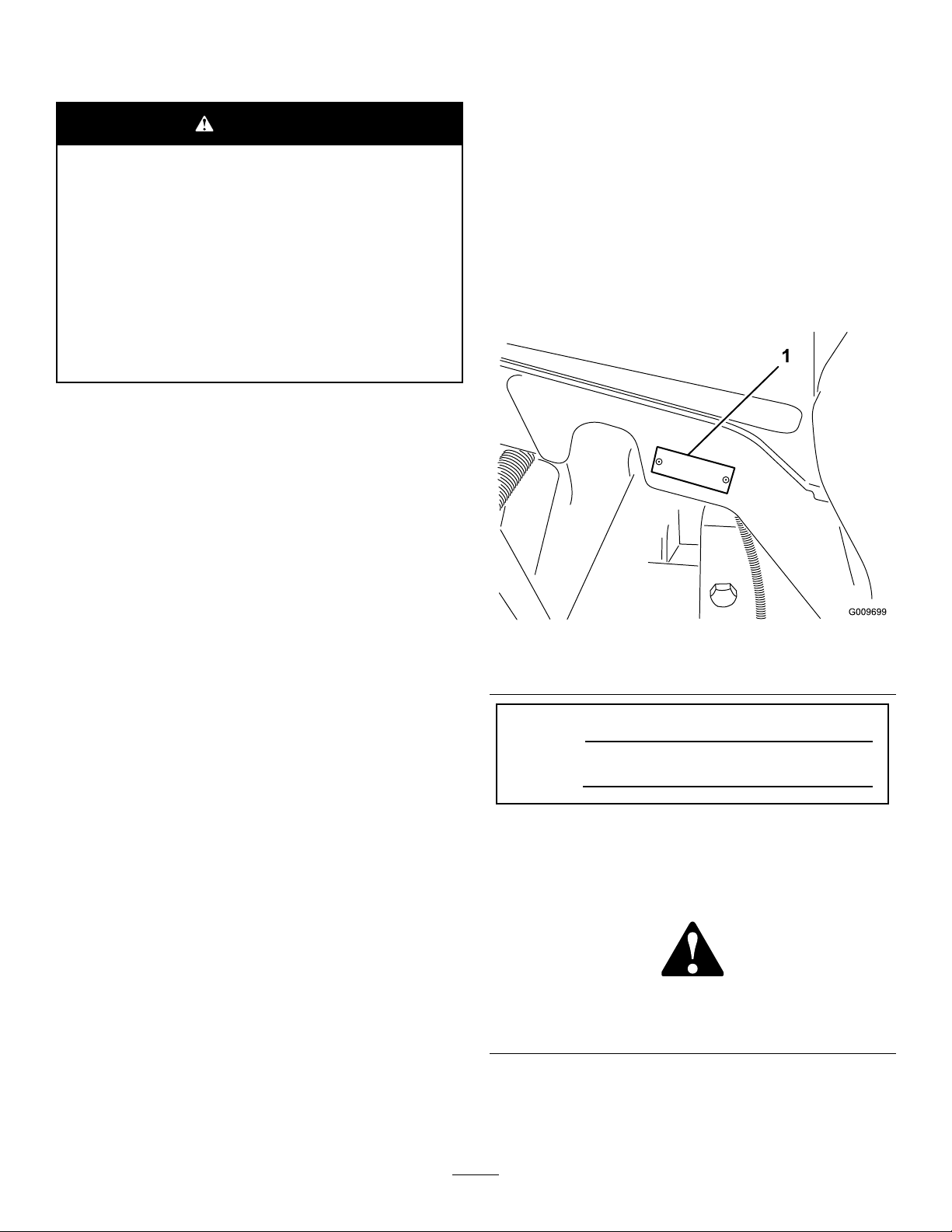
SafetyandInstructionalDecals
Safetydecalsandinstructionsareeasilyvisibletotheoperatorandarelocatednearanyarea
ofpotentialdanger.Replaceanydecalthatisdamagedorlost.
117-4763
decal117-4765
117-4765
1.ReadtheOperator'sManual.
2.Donotusestartingaids.
decal117-4763
1.Toengagetheparking
brake,securethebrake
pedalswiththelockingpin,
presstheparkingbrake
pedalsandengagethetoe
pedal.
1.Hydraulicoil
2.ReadtheOperator'sManual.
2.Todisengagetheparking
93-6680
93-6686
brake,disengagethe
lockingpinandreleasethe
pedals.
decal117-4766
117-4766
1.Cutting/dismembermenthazard;fan—stayawayfrom
movingparts.
decal93-6680
decal117-2718
117–2718
decal93-6686
decal106-6755
106-6755
1.Enginecoolantunder
2.Explosionhazard—read
8
pressure.
theOperator'sManual.
3.Warning—donottouchthe
hotsurface.
4.Warning—readthe
Operator'sManual.

1.Warning—wearhearingprotection.
decal98-4387
98-4387
decal93-6688
93-6688
1.Warning—readthe
instructionsbefore
servicingorperforming
maintenance.
2.Cuttinghazardofhandor
foot—stoptheengineand
waitformovingpartsto
stop.
110-9642
1.Storedenergyhazard—readtheOperator'sManual.
2.Movethecotterpintotheholeclosesttotherodbracket
andthenremovetheliftarmandpivotyoke.
decal125-8754
decal110-9642
1.Headlights
125–8754
6.Slow
2.Engage7.Lowerthecuttingunits
3.Powertake-off(PTO)
4.Disengage
8.Raisethecuttingunits
9.ReadtheOperator’s
Manual.
5.Fast
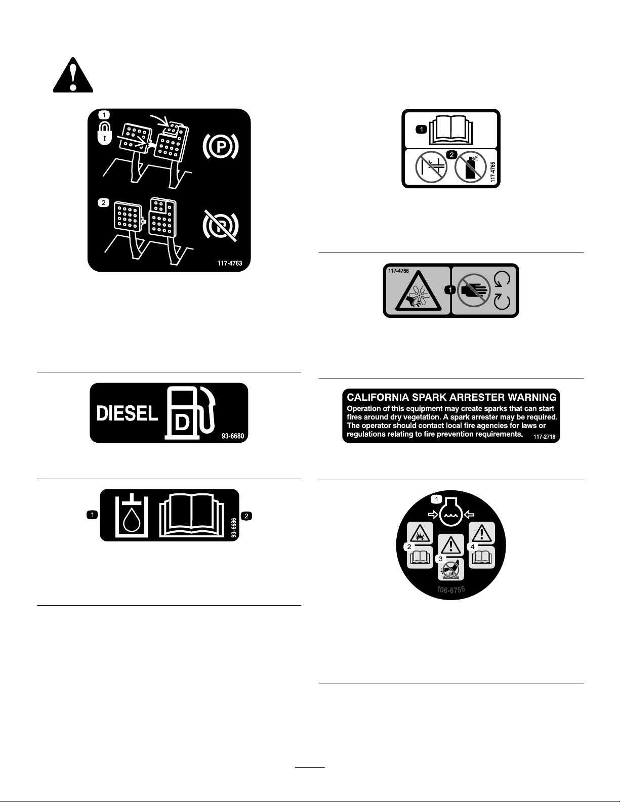
1.ReadtheOperator’sManual.
9
decal121-3887
121–3887
121–3884
1.Engine—stop3.Engine—start
2.Engine—preheat
112-5019
93–6681
1.Cutting/dismembermenthazard—stayawayfrommoving
parts.
decal121-3884
decal125-4605
125–4605
decal112-5019
decal93-6681
1.Powerseat,10A6.Powersupplied,10A
2.Worklight,10A
7.Controller,2A
3.Engine,10A8.Powersupplied,7.5A
4.Cigarettelighter,10A9.Controller,2A
5.Infocenter,2A
10.Enginepreheat,60A
106-6754
1.Warning—donottouchthehotsurface.
2.Cutting/dismembermenthazard,fanandentanglement
hazard,belt—stayawayfrommovingparts.
decal120-1670
120-1670
decal106-6754
1.Tractionunitspeed3.Fast
2.Slow
10

BatterySymbols
Someorallofthesesymbolsareonyourbattery
decalbatterysymbols
130-1651
1.ReadtheOperator'sManualformoreinformationof
servicingthemachine.
1.Explosionhazard
6.Keepbystandersasafe
distancefromthebattery.
2.Nore,opename,or
smoking.
7.Weareyeprotection;
explosivegasescan
causeblindnessandother
injuries
3.Causticliquid/chemical
burnhazard
8.Batteryacidcancause
blindnessorsevereburns.
4.Weareyeprotection9.Flusheyesimmediately
withwaterandgetmedical
helpfast.
5.ReadtheOperator's
Manual.
decal130-1651
10.Containslead;donot
discard.
11
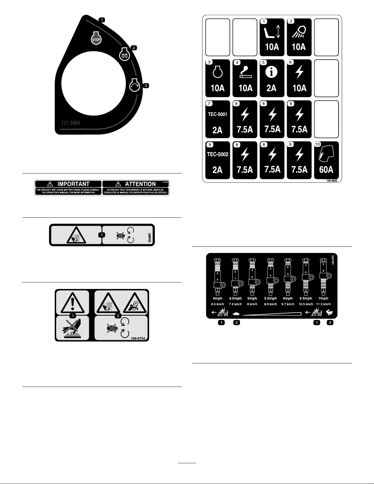
decal120-1683
120-1683
1.Warning—readtheOperator'sManual,donotoperatethis
machineunlessyouaretrained.
2.Warning—readtheOperator'sManualbeforetowingthe
machine.
3.Tippinghazard—slowmachinebeforeturning,donotturnat
highspeeds;lowerthecuttingunitwhendrivingdownslopes;
usearolloverprotectionsystemandweartheseatbelt
4.Warning—donotparkthemachineonslopes;engagethe
parkingbrake,lowerthecuttingunits,stoptheengineand
removetheignitionkeybeforeleavingthemachine.
5.Thrownobjecthazard—keepbystandersasafedistancefrom
themachine.
6.Entanglementhazard,belt—stayawayfrommovingparts,
keepallguardsandshieldsinplace.
12
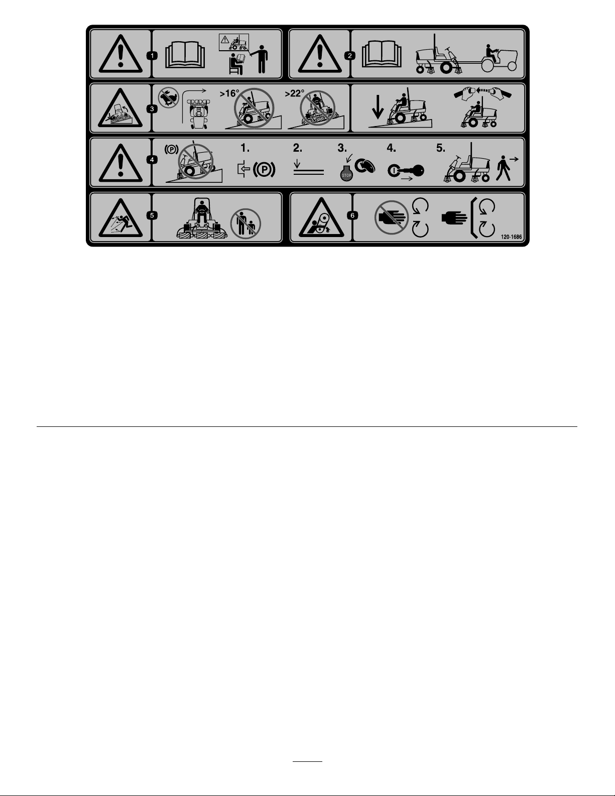
decal120-1686
120-1686
Afxoverpartno.120–1683forCE*
*ThissafetydecalincludesaslopewarningrequiredonthemachinefrocompliancetotheEuropeanLawnMowerStandardENISO5395:2013.Theconservativemaximumslope
anglesindicatedforoperationofthismachineareprescribedbyandrequiredbythisstandard.
1.Warning—readtheOperator'sManual,donotoperatethis
machineunlessyouaretrained.
2.Warning—readtheOperator'sManualbeforetowingthe
machine.
3.Tippinghazard—donotturnathighspeeds,donotupand
downslopesgreaterthan16degrees,donotmowacross
slopesgreaterthan22degrees;lowerthecuttingunitwhen
drivingdownslopes;usearolloverprotectionsystemand
weartheseatbelt
4.Warning—donotparkthemachineonslopes;engagethe
parkingbrake,lowerthecuttingunits,stoptheengineand
removetheignitionkeybeforeleavingthemachine.
5.Thrownobjecthazard—keepbystandersasafedistancefrom
themachine.
6.Entanglementhazard,belt—stayawayfrommovingparts,
keepallguardsandshieldsinplace.
13

Setup
LooseParts
Usethechartbelowtoverifythatallpartshavebeenshipped.
ProcedureDescription
1
2
3
4
5
6
7
8
9
Nopartsrequired
Warningdecal1
Hoodlockbracket1
Rivet2
Screw,1/4x2inch
Flatwasher,1/4inch
Locknut,1/4inch
Fronthoseguide-R.H.1
Fronthoseguide-L.H.1
Nopartsrequired
Cuttingunitkickstand
Nopartsrequired
Nopartsrequired
Gaugebar
Qty.
Use
–
1
2
1
–
1
–
–
1
Adjustthesupportrollers
UsedonlyonmachinesrequiringCE
Compliance.
Usedonlyonmachinesrequiring
EuropeanCECompliance.
Installthecuttingunits
Adjusttheturfcompensationspring.
InstalltheCuttingUnitKickstand.
Greasethemachine.
Checktherearaxlelubricant,hydraulic
uid,andengineoillevels
Usethegaugebartoadjustthecutting
unit.
MediaandAdditionalParts
Description
Operator'sManual
EngineOperator'sManual
PartsCatalog
OperatorTrainingMaterial
DeclarationofConformity
Note:Determinetheleftandrightsidesofthemachinefromthenormaloperatingposition.
Qty.
1
1
1
1
1
Readbeforeoperatingmachine
Readbeforeoperatingengine
Usetoreferencepartnumbers
Viewbeforeoperatingmachine
UseforCECompliance
Use
14

1
2
AdjustingtheSupport Rollers
NoPartsRequired
Procedure
Dependingonwhatwidthcuttingunitsaretobe
installedonthetraction,adjustthesupportrollersas
follows:
•Ifusing27inchcuttingunits,therollersaretobe
installedintheuppermountingholesofsupport
assemblychannels(Figure3).
•Ifusing32inchcuttingunits,therollersaretobe
installedinthelowermountingholesofsupport
assemblychannels(Figure3).
ReplacingtheWarning DecalforCECompliance
Partsneededforthisprocedure:
1Warningdecal
Procedure
OnmachinesrequiringCECompliance,afxthe
warningdecal,partno.120–1683overthewarning
decalpartno.120–1686.
3
InstallingtheHoodLockfor CECompliance
Figure3
1.Supportassemblychannel3.Usethisholefor32inch
cuttingunits
2.Usethisholefor27inch
cuttingunits
Partsneededforthisprocedure:
1Hoodlockbracket
2Rivet
1
Screw,1/4x2inch
2
Flatwasher,1/4inch
1
Locknut,1/4inch
g019541
Procedure
1.Unhookthehoodlatchfromthehoodlatch
bracket(Figure4).
15

Figure6
g012629
Figure4
1.Hoodlatch
2.Removethe(2)rivetssecuringthehoodlatch
brackettothehood(Figure5).Removethe
hoodlatchbracketfromthehood.
Figure5
1.CElockbracket
g014982
2.Boltandnutassembly
4.Alignthewasherswiththeholesontheinsideof
thehood.
5.Rivetthebracketsandthewasherstothehood
(Figure6).
6.Hookthelatchontothehoodlatchbracket
(Figure7).
g012630
Figure7
g012628
1.Hoodlatch
1.Hoodlatchbracket2.Rivets
3.Whilealigningthemountingholes,positionthe
CElockbracketandthehoodlatchbracketonto
thehood.Thelockbracketmustbeagainstthe
hood(Figure5).Donotremoveboltandnut
assemblyfromthelockbracketarm.
7.Screwtheboltintotheotherarmofhoodlock
brackettolockthelatchinposition(Figure8).
Tightenboltsecurelybutdonottightennut.
16

Figure8
g012631
1.Bolt
2.Nut
3.Armofhoodlockbracket
4
InstallingtheCuttingUnits
Partsneededforthisprocedure:
1Fronthoseguide-R.H.
1Fronthoseguide-L.H.
Procedure
1.Removethereelmotorsfromtheshipping
brackets.
2.Removetheshippingbracketsanddiscard.
3.Removethecuttingunitsfromthecartons.
Assembleandadjustasdescribedinthecutting
unitOperator'sManual.
g003320
Figure9
1.Counterweight
5.Allthecuttingunitsareshippedwiththeturf
compensationspringmountedtotherightside
ofthecuttingunit.Theturfcompensationspring
mustbemountedtothesamesideofthecutting
unitasthereeldrivemotor.Repositiontheturf
compensationasfollows:
A.Removethe2carriageboltsandnuts
securingtherodbrackettothecuttingunit
tabs(Figure10).
4.Makesurethecounterweight(Figure9)is
installedtotheproperendofthecuttingunitas
describedinthecuttingunitOperator'sManual.
g003949
Figure10
1.Turfcompensationspring3.Springtube
2.Rodbracket
B.Removetheangenutsecuringthespring
tubebolttothecarrierframetab(Figure10)
Removetheassembly.
C.Mountthespringtubebolttotheopposite
tabonthecarrierframeandsecurewiththe
angenut.Theboltheadistobepositioned
totheoutersideofthetabasshownin
Figure11.
17

Figure11
g003967
1.Oppositecarrierframetab
2.Rodbracket
D.Mounttherodbrackettothecuttingunit
tabswiththecarriageboltsandnuts(Figure
11).Also,onthecuttingunit,mounttheleft
handhoseguidetothefrontofthecutting
unittabswhenreinstallingtherodbracket
(Figure13).
Important:Onthe#4(leftfront)and
#5(rightfront)cuttingunits,usethe
rodbracketmountingnutstoinstallthe
hoseguidestothefrontofthecutting
unittabs.Thehoseguidesshouldlean
towardthecentercuttingunit(Figure12
throughFigure14).
Figure12
g015160
Figure13
1.Hoseguide(Lefthand
shown)
2.Rodbracket
g014684
3.Nuts
1.Hoseguides(eachmustleantowardthecentercuttingunit)
Note:Wheninstallingorremovingthe
cuttingunits,makesurethehairpincotteris
installedinthespringrodholenexttothe
rodbracket.Otherwise,thehairpincotter
mustbeinstalledintheholeintheendof
therod.
g019602
Figure14
6.Increasethesteeringontherearcuttingunits
byremovingthe(2)pivotspacers,hexsocket
screwsandangelocknuts(Figure15)from
therear(#2and#3)cuttingunitcarrierframes
(Figure12).
18

Figure15
9.Forthefrontcuttingunits,slideacuttingunit
undertheliftarmwhileinsertingthecarrier
frameshaftupintotheliftarmpivotyoke(Figure
16).Makesurethethrustwasherisinposition
onthecarrierframeshaft.
10.Securethecarrierframeshafttotheliftarm
yokewiththeKlikpin(Figure16).
11.Tolock(x)thesteeringonthecuttingunits,
securethepivotyoketothecarrierframewith
thesnapperpin(Figure17).
g015978
1.Hexsocketscrew
2.Pivotspacer4.Flangelocknut
3.Carrierframe
7.Loweralltheliftarmscompletely .
8.Coatthecarrierframeshaftwithcleangrease
(Figure16).
g015977
Figure17
1.Snapperpin
Note:Fixedsteeringisrecommendedwhen
cuttingsidehills.
12.Usethefollowingprocedureontherearcutting
unitswhentheheightofcutisabove3/4inch.
A.Removethelynchpinandwashersecuring
theliftarmpivotshafttotheliftarmand
slidetheliftarmpivotshaftoutoftheliftarm
(Figure18).
Figure16
1.Liftarmpivotyoke4.Carrierframeshaft
2.Liftarm
3.Klikpin
5.Thrustwasher
g003979
Figure18
1.Liftarmpivotshaftlynchpinandwasher
B.Inserttheliftarmyokeontothecarrier
g015976
frameshaft(Figure16).
C.Inserttheliftarmshaftintotheliftarmand
secureitwiththewasherandlynchpin
(Figure18).
13.Securetheliftarmchaintothechainbracket
withthesnapperpin(Figure19).Usethe
19

numberofchainlinksdescribedinthecutting
unitOperator'sManual.
5
AdjustingtheTurf CompensationSpring
NoPartsRequired
Figure19
1.Liftarmchain3.Snapperpin
2.Chainbracket
14.Coatthesplineshaftofthereelmotorwithclean
grease.
15.OilthereelmotorO-ringandinstallitontothe
motorange.
16.Installthemotorbyrotatingitclockwisesothat
themotorangesclearthebolts(Figure20).
Rotatethemotorcounterclockwiseuntilthe
angesencircletheboltsthentightenthebolts.
Important:Makesurethereelmotorhoses
arenottwisted,kinkedorintheriskofbeing
pinched.
g003948
Procedure
Theturfcompensationspring(Figure21)transfers
weightfromthefronttotherearroller.(Thishelps
toreduceawavepatternintheturf,alsoknownas
marcellingorbobbing.)
Important:Makespringadjustmentswiththe
cuttingunitmountedtothetractionunit,pointing
straightaheadandloweredtotheshopoor.
1.Makesurethehairpincotterisinstalledinthe
rearholeinthespringrod(Figure21).
Note:Whenservicingthecuttingunit,movethe
hairpincottertothespringrodholenexttothe
turfcompensationspring.
Figure20
1.Reeldrivemotor2.Mountingbolts
g003863
Figure21
1.Turfcompensationspring3.Springrod
2.Hairpincotter4.Hexnuts
2.Tightenthehexnutsonthefrontendofthe
springroduntilthecompressedlengthofthe
g004127
springis6.25inches(15.9cm)(Figure21).
Note:Whenoperatingonroughterrain
decreasethespringlengthby1/2inch.Ground
followingwillbeslightlydecreased.
Note:Theturfcompensationsettingwill
needtoberesetiftheHOCsettingorthe
AggressivenessofCutsettingischanged.
20

6
UsingtheCuttingUnit
Kickstand
Partsneededforthisprocedure:
1
Cuttingunitkickstand
Procedure
Wheneverthecuttingunithastobetippedtoexpose
thebedknife/reel,propuptherearofthecuttingunit
withthekickstandtomakesurethenutsontheback
endofthebedbaradjustingscrewsarenotrestingon
theworksurface(Figure22).
g004144
Figure23
1.Chainbracket3.Cuttingunitkickstand
2.Snapperpin
Figure22
1.Cuttingunitkickstand
Securethekickstandtothechainbracketwiththe
snapperpin(Figure23).
7
GreasingtheMachine
NoPartsRequired
Procedure
Beforethemachineisoperated,itmustbegreased
g003985
toensureproperlubrication.RefertoLubrication
section.Failuretoproperlygreasethemachinewill
resultinprematurefailureofcriticalparts.
21

8
CheckingFluidLevels
NoPartsRequired
Procedure
1.Checktherearaxlelubricantlevelbeforethe
engineisrststarted,refertoCheckingtheRear
AxleLubricantinDriveSystemMaintenance.
2.Checkthehydraulicuidlevelbeforetheengine
isrststarted,refertoCheckingtheHydraulic
FluidLevelinOperation.
3.Checktheengineoillevelbeforeandafterthe
engineisrststarted,refertoCheckingthe
EngineOilLevelinOperation.
9
UsingtheGaugeBar
Partsneededforthisprocedure:
1
Gaugebar
Procedure
Usethegaugebartoadjustthecuttingunit.Referto
theCuttingUnitOperator'sManualfortheadjustment
procedures(Figure24).
g004552
Figure24
1.Gaugebar4.Holesusedforsetting
GroomerHOG
2.Heightadjustingscrew5.Holenotused
3.Nut
22

ProductOverview
Controls
BrakePedals
Twofootpedals(Figure25)operateindividualwheel
brakesforturningassistanceandtoaidinobtaining
bettersidehilltraction.
PedalLockingLatch
Thepedallockinglatch(Figure25)connectsthe
pedalstogethertoengagetheparkingbrake.
TiltSteeringPedal
Totiltthesteeringwheeltowardsyou,pressthefoot
pedal(Figure25)down,andpullthesteeringtower
towardyoutothemostcomfortablepositionandthen
releasethepedal.
MowSpeedLimiter
Whenthemowspeedlimiter(Figure26)isippedup
itwillcontrolthemowspeedandallowthecutting
unitstobeengaged.Eachspaceradjuststhemowing
speedby½mileperhour.Themorespacersyou
have,onthetopoftheboltthesloweryouwillgo.For
transport,ipbackthemowspeedlimiterandyouwill
havemaximumtransportspeed.
ParkingBrakePedal
Toengagetheparkingbrake,(Figure25)connectthe
pedalstogetherwiththepedallockinglatch,push
downontherightbrakepedalwhileengagingthetoe
pedal.Toreleasetheparkingbrake,pressoneofthe
brakepedalsuntiltheparkingbrakelatchretracts.
Figure25
1.Brakepedal4.Tractionpedal
2.Pedallockinglatch5.Tiltsteeringpedal
3.Parkingbrakepedal
SpeedLimiterScrews
Adjustthescrew(s)(Figure26)tolimittheamount
thetractionpedalcanbedepressedintheforwardor
reversedirectiontolimitspeed.
Important:Thespeedlimiterscrewmuststopthe
tractionpedalbeforethepumpreachesfullstroke
ordamagetothepumpmayoccur.
g015074
g015075
Figure26
1.Reversespeedlimiter
screw
2.Forwardspeedlimiter
screw
3.Spacers
4.Mowspeedlimiter
TractionPedal
Thetractionpedal(Figure25)controlsforwardand
reverseoperation.Depressthetopofthepedalto
moveforwardandthebottomtomovebackward.
Groundspeeddependsonhowfarthepedalis
depressed.Fornoload,maximumgroundspeed,fully
depressthepedalwhilethethrottleisinFast.
Tostop,reduceyourfootpressureonthetraction
pedalandallowittoreturntothecenterposition.
LowerMow/RaiseControlLever
Thislever(Figure27)raisesandlowersthecutting
unitsandalsostartsandstopsthecutterheads
whenthecutterheadsareenabledinthemowmode.
Thecutterheadscannotbeloweredwhenthe
mow/transportleverisinthetransportposition.
KeySwitch
Thekeyswitch(Figure27)hasthreepositions:Off,
On/Preheat,andStart.
23

InfoCenter
TheInfoCenterLCDdisplayshowsinformationabout
yourmachinesuchastheoperatingstatus,various
diagnosticsandotherinformationaboutthemachine
(Figure27).
PTOSwitch
ThePTOswitch(Figure27)hastwopositions:Out
(start)andIn(stop).PullthePTObuttonoutto
engagethecuttingunitblades.Pushinthebuttonto
disengagethecuttingunitblades.
g010239
Figure28
1.Powerpoint2.Bagholder
BagHolder
Figure27
1.Lowermow/raisecontrol
lever
2.Keyswitch5.Enginespeedswitch
3.InfoCenter
4.PTOswitch
6.Headlightswitch
EngineSpeedSwitch
Theenginespeedswitch(Figure27)hastwomodes
tochangetheenginespeed.Bymomentarilytapping
theswitch,theenginespeedcanbeincreasedor
decreasedin100rpmincrements.Byholdingthe
switchdowntheenginewillautomaticallymoveto
HighorLowidle,dependingonwhichendofthe
switchisdepressed.
HeadlightSwitch
Pivottheswitchdownwardtoturnontheheadlights
(Figure27).
g021208
Usethebagholder(Figure28)forstorage.
BacklapLevers
Usethebacklapleversforbacklappingthereels
(Figure29).
PowerPoint
Thepowerpoint(Figure28)isusedtopoweroptional
12voltelectricalaccessories.
g015076
Figure29
1.Frontbacklaplever2.Rearbacklaplever
24

SeatAdjustments
UsingtheInfoCenterLCDDisplay
ForeandAftAdjustingLever
Pulloutonthelevertoslidetheseatforeoraft(Figure
30).
SeatArmRestAdjustingKnob
Rotatetheknobtoadjusttheseatarmrestangle
(Figure30).
SeatBackAdjustingLever
Movethelevertoadjusttheseatbackangle(Figure
30).
Weightgauge
Indicateswhentheseatisadjustedtotheweightof
theoperator(Figure30).Heightadjustmentismade
bypositioningthesuspensionwithintherangeofthe
greenregion.
TheInfoCenterLCDdisplayshowsinformationabout
yourmachinesuchastheoperatingstatus,various
diagnostics,andotherinformationaboutthemachine
(Figure31)Thereisasplashscreenandmain
informationscreenoftheInfoCenter.Youcanswitch
betweenthesplashscreenandmaininformation
screen,atanytime,bypressinganyoftheInfoCenter
buttonsandthenselectingtheappropriatedirectional
arrow.
g020650
Figure31
Figure30
1.Weightgauge
2.Weightadjustinglever5.Armrestadjustingknob
3.ForeandAftadjusting
lever
WeightAdjustingLever
4.Seatbackadjustinglever
Adjustforoperatorweight(Figure30).Pulluponthe
levertoincreasetheairpressureandpushdownto
decreasetheairpressure.Theproperadjustmentis
attainedwhentheweightgaugeisinthegreenregion.
1.Indicatorlight3.Middlebutton
2.Rightbutton
4.Leftbutton
•LeftButton,MenuAccess/BackButton—pressthis
buttontoaccesstheInfoCentermenus.Youcan
useittobackoutofanymenuyouarecurrently
using.
•MiddleButton—usethisbuttontoscrolldown
menus.
•RightButton—usethisbuttontoopenamenu
wherearightarrowindicatesadditionalcontent.
g008837
•ManualFanReversal—activatedbypressingthe
leftandrightbuttonssimultaneously.
•Beeper—activatedwhenloweringthedecksorfor
advisoriesandfaults.
Note:Thepurposeofeachbuttonmaychange
dependingonwhatisrequiredatthetime.Each
buttonwillbelabeledwithanicondisplayingits
currentfunction.
25

InfoCenterIconDescription
SERVICEDUE
Indicateswhenscheduledservice
shouldbeperformed
Enginerpm/status—indicatesthe
enginespeed
Infoicon
InfoCenterIconDescription(cont'd.)
Stoporshutdown
Engine
Hourmeter
Fast
Slow
Fanreversal—indicateswhenthefan
isreversed
Stationaryregenerationrequired
Airintakeheaterisactive
Raisecuttingunits
Lowercuttingunits
Operatormustsitinseat
Keyswitch
Indicateswhenthecuttingunitsare
beinglowered
Indicateswhenthecuttingunitsare
beingraised
PINcode
Hydraulicuid
temperature—indicatesthe
temperatureofthehydraulicuid
CANbus
InfoCenter
Badorfailed
Bulb
OutputofTECcontrollerorcontrol
wireinharness
High:overallowedrange
Parkingbrakeindicator—indicates
whentheparkingbrakeisOn
IdentiestherangeasHigh
Neutral
IdentiestherangeasLow
Coolanttemperature—indicatesthe
enginecoolanttemperatureineither
°Cor°F
Temperature(hot)
Deniedornotallowed
PTOisengaged
EngineStart
Low:underallowedrange
Outofrange
/
Switch
Operatormustreleaseswitch
Operatorshouldchangetoindicated
state
Symbolsareoften
combinedtoform
sentences.Some
examplesareshown
below
Operatorshouldputmachinein
neutral
Enginestartdenied
Engineshutdown
26

InfoCenterIconDescription(cont'd.)
Enginecoolanttoohot
Hydraulicuidtoohot
Hours
Counts
Liststhetotalnumberofhours
thatthemachine,engineand
PTOhavebeenon,aswell
asthenumberofhoursthe
machinehasbeentransported
andservicedue.
Listsnumerouscountsthe
machinehasexperienced.
DPFashaccumulation
notication.RefertoServicing
theDiesel-OxidationCatalyst(DOC)
andtheSootFilter(page54)inthe
maintenancesectionfordetails.
Sitdownorsetparkingbrake
UsingtheMenus
ToaccesstheInfoCentermenusystem,pressthe
menuaccessbuttonwhileatthemainscreen.This
willbringyoutothemainmenu.Refertothefollowing
tablesforasynopsisoftheoptionsavailablefrom
themenus:
MainMenu
MenuItemDescription
FaultsTheFaultsmenucontains
alistoftherecentmachine
faults.RefertotheService
ManualoryourAuthorized
ToroDistributorformore
informationontheFaults
menuandtheinformation
containedthere.
ServiceTheServicemenucontains
informationonthemachine
suchashoursofusecounters
andothersimilarnumbers.
DiagnosticsTheDiagnosticsmenu
displaysthestateofeach
machineswitch,sensorand
controloutput.Y oucanuse
thistotroubleshootcertain
issuesasitwillquicklytellyou
whichmachinecontrolsareon
andwhichareoff.
SettingsTheSettingsmenuallows
youtocustomizeandmodify
congurationvariablesonthe
InfoCenterdisplay.
AboutTheAboutmenuliststhe
modelnumber,serialnumber,
andsoftwareversionofyour
machine.
Service
MenuItemDescription
Diagnostics
MenuItemDescription
CuttingUnitsIndicatestheinputs,qualiers,
Hi/LowRangeIndicatestheinputs,qualiers,
PTOIndicatestheinputs,qualiers,
EngineRun
Backlap
Settings
MenuItemDescription
Units
Language
LCDBacklightControlsthebrightnessofthe
LCDContrastControlsthecontrastofthe
FrontBacklapReelSpeedControlsthespeedofthefront
RearBacklapReelSpeedControlsthespeedoftherear
ProtectedMenusAllowsapersonauthorized
AutoIdle
BladeCountControlsthenumberofblades
MowSpeedControlsthegroundspeedfor
Heightofcut(HOC)Controlstheheightofcut
andoutputsforraisingand
loweringthecuttingunits.
andoutputsfordrivingin
transportmode.
andoutputsforenablingthe
PTOcircuit.
Indicatestheinputs,qualiers,
andoutputsforstartingthe
engine.
Indicatestheinputs,qualiers,
andoutputsforoperatingthe
backlapfunction.
Controlstheunitsusedonthe
InfoCenter.Themenuchoices
areEnglishorMetric
Controlsthelanguageused
ontheInfoCenter*.
LCDdisplay.
LCDdisplay.
reelsinbacklapmode.
reelsinbacklapmode.
byyourcompanywiththe
PINcodetoaccessprotected
menus.
Controlstheamountoftime
allowedbeforereturningthe
enginetolowidlewhenthe
machineisstationary.
onthereelforreelspeed.
determiningthereelspeed.
(HOC)fordeterminingthereel
speed.
27

FReelRPMDisplaysthecalculatedreel
speedpositionforthefront
reels.Thereelscanalsobe
manuallyadjusted.
RReelRPMDisplaysthecalculatedreel
speedpositionfortherear
reels.Thereelscanalsobe
manuallyadjusted.
*Only"operator-faced"textistranslated.Faults,
Service,andDiagnosticsscreensare"service-faced".
Titleswillbeintheselectedlanguage,butmenuitems
areinEnglish.
g028523
Figure32
About
MenuItemDescription
Model
SNListstheserialnumberofthe
MachineControllerRevisionListsthesoftwarerevisionof
InfoCenterRevisionListsthesoftwarerevisionof
CANBus
Liststhemodelnumberofthe
machine.
machine.
themastercontroller .
theInfoCenter.
Liststhemachine
communicationbusstatus.
ProtectedMenus
Thereare8operatingcongurationsettingsthatare
adjustablewithintheSettingsMenuoftheInfoCenter:
autoidletimedelay ,BladeCount,MowSpeed,Height
ofCut(HOC),FReelRPMandRReelRPM.These
settingscanbelockedbyusingtheProtectedMenu.
Note:Atthetimeofdelivery,theinitialpassword
codeisprogrammedbyyourdistributor.
AccessingProtectedMenus
2.IntheSETTINGSMENU,usethecenterbuttonto
scrolldowntothePROTECTEDMENUandpress
therightbutton(Figure33A).
g028522
Figure33
Note:ThefactorydefaultPINcodeforyoumachine
iseither0000or1234.
IfyouchangedthePINcodeandforgotthe
code,contactyourAuthorizedToroDistributorfor
assistance.
1.FromtheMAINMENU,usethecenterbuttonto
scrolldowntotheSETTINGSMENUandpressthe
rightbutton(Figure32).
3.T oenterthePINcode,pressthecenterbutton
untilthecorrectrstdigitappears,thenpress
therightbuttontomoveontothenextdigit
(Figure33BandFigure33C).Repeatthisstep
untilthelastdigitisenteredandpresstheright
buttononcemore.
4.PressthemiddlebuttontoenterthePINcode
(Figure33D).
WaituntiltheredindicatorlightoftheInfoCenter
illuminates.
Note:IftheInfoCenteracceptsthePINcode
andtheprotectedmenuisunlocked,theword
“PIN”displaysintheupperrightcornerofthe
screen.
28

Note:RotatethekeyswitchtotheOFFpositionand
thentotheONpositionlockstheprotectedmenu.
Youhavetheabilitytoviewandchangethesettingsin
theProtectedMenu.OnceyouaccesstheProtected
Menu,scrolldowntoProtectSettingsoption.Usethe
rightbuttontochangethesetting.SettingtheProtect
SettingstoOFFallowsyoutoviewandchangethe
settingsintheProtectedMenuwithoutenteringthe
PINcode.SettingtheProtectSettingstoONhidesthe
protectedoptionsandrequiresyoutoenterthePIN
codetochangethesettingintheProtectedMenu.
AfteryousetthePINcode,rotatethekeyswitchOFF
andbacktotheONpositiontoenableandsavethis
feature.
ToSettheAutoIdle
•IntheSettingsMenu,scrolldowntoAutoIdle.
ToSettheFrontandRearReel
Speeds
Althoughthefrontandrearreelspeedsarecalculated
byinputtingthenumberofblades,mowspeedand
HOCintotheInfoCenter,thesettingcanbemanually
changedtoaccommodatefordifferentmowing
conditions.
•TochangetheReelSpeedSettings,scrolldownto
theFReelRPM,RReelRPMorboth.
•Presstherightbuttontochangethereelspeed
value.Asthespeedsettingischanged,thedisplay
willcontinuetoshowthecalculatedreelspeed
basedonbladecount,mowspeedandHOCwhich
waspreviouslyentered,butthenewvaluewillalso
bedisplayed.
•Presstherightbuttontochangetheautoidletime
betweenOFF ,8S,10S,15S,20S,&30S.
ToSettheBladeCount
•IntheSettingsMenu,scrolldowntoBladeCount
•Presstherightbuttontochangethebladecount
between5,8or11bladereels.
ToSettheMowSpeed
•IntheSettingsMenu,scrolldowntoMowSpeed.
•Presstherightbuttontoselectmowspeed.
•Usethecenterandrightbuttontoselectthe
appropriatemowspeedsetonthemechanical
mowspeedlimiteronthetractionpedal.
•Presstheleftbuttontoexitmowspeedandsave
thesetting.
ToSettheHeightofCut(HOC)
•IntheSettingsMenu,scrolldowntoHOC.
•PresstherightbuttontoselectHOC.
•Usethecenterandrightbuttontoselectthe
appropriateHOCsetting.(Iftheexactsettingis
notdisplayed,selectthenearestHOCsettingfrom
thelistdisplayed).
•PresstheleftbuttontoexitHOCandsavethe
setting.
Specications
Note:Specicationsanddesignaresubjectto
changewithoutnotice.
TractionUnitSpecications
Widthofcut,27inchcutting
units
Widthofcut,32inchcutting
units
Overallwidth,27inchcutting
unitsdown
Overallwidth,32inchcutting
unitsdown
Overallwidth,cuttingunitsup
(transport)
Overalllength370cm(145.8inches)
HeightwithROPS220cm(87inches)
TrackWidth,front229cm(90inches)
TrackWidth,rear
Wheelbase
NetWeight(withnocutting
unitsandnouids)
Attachments/Accessories
AselectionofToroapprovedattachmentsand
accessoriesisavailableforusewiththemachineto
enhanceandexpanditscapabilities.Contactyour
AuthorizedServiceDealerorDistributororgoto
www.T oro.comforalistofallapprovedattachments
andaccessories.
307cm(121inches)
320cm(126inches)
345cm(136inches)
358cm(141inches)
239cm(94inches)
141cm(55.5inches)
171cm(67-1/2inches)
1574kg(3470lb)
29

Operation
Note:Determinetheleftandrightsidesofthe
machinefromthenormaloperatingposition.
CAUTION
Thismachineproducessoundlevelsin
excessof85dBAattheoperator'searand
cancausehearinglossthroughextended
periodsofexposure.
Wearhearingprotectionwhenoperatingthis
machine.
CAUTION
Ifyouleavethekeyintheignitionswitch,
someonecouldaccidentlystarttheengine
andseriouslyinjureyouorotherbystanders.
Removethekeyfromtheignitionbeforeyou
doanymaintenance.
CheckingtheEngine-Oil Level
Beforeyoustarttheengineandusethemachine,
checktheoillevelintheenginecrankcase;referto
CheckingtheEngine-OilLevel(page53).
CheckingtheCooling System
ServiceInterval:Beforeeachuseordaily
Checklevelofcoolantatthebeginningofeachday.
Capacityofsystemis12.3liters(13quarts).
g009702
Figure34
1.Expansiontank
2.Checkthecoolantlevelintheradiator.The
radiatorshouldbelledtothetopoftheller
neckandtheexpansiontanklledtotheFULL
mark(Figure34).
3.Ifthecoolantislow,adda50/50mixtureofwater
andethyleneglycolantifreeze.Donotuse
wateronlyoralcohol/methanolbasecoolants.
4.Installtheradiatorcapandexpansiontankcap.
1.Carefullyremovetheradiatorcap.
CAUTION
Iftheenginehasbeenrunning,the
pressurized,hotcoolantcanescapeand
causeburns.
•Donotopentheradiatorcapwhenthe
engineisrunning.
•Usearagwhenopeningtheradiator
cap,andopenthecapslowlytoallow
steamtoescape.
30

FillingtheFuelTank
DANGER
Incertainconditions,fuelisextremely
ammableandhighlyexplosive.Areor
explosionfromfuelcanburnyouandothers
andcandamageproperty.
WARNING
Fuelisharmfulorfatalifswallowed.
Long-termexposuretovaporscancause
seriousinjuryandillness.
•Avoidprolongedbreathingofvapors.
•Keepyourfaceawayfromthenozzleand
fueltankopening.
•Fillthefueltanksoutdoors,inanopen
area,whentheengineiscold.Wipeupany
fuelthatspills.
•Neverllthefueltanksinsideanenclosed
trailer.
•Neversmokewhenhandlingfuelandstay
awayfromanopenameorwherefuel
fumesmaybeignitedbyaspark.
•Storefuelinanapprovedcontainerand
keepitoutofthereachofchildren.Never
buymorethana30-daysupplyoffuel.
•Donotoperatewithoutentireexhaust
systeminplaceandinproperworking
condition.
DANGER
Incertainconditionsduringfueling,static
electricitycanbereleased,causingaspark
thatcanignitethefuelvapors.Areor
explosionfromfuelcanburnyouandothers
andcandamageproperty.
•Alwaysplacefuelcontainersontheground
awayfromyourvehiclebeforelling.
•Donotllfuelcontainersinsideavehicle
oronatruckortrailerbed,becauseinterior
carpetsorplastictruckbedlinersmay
insulatethecontainerandslowthelossof
anystaticcharge.
•Whenpractical,removeequipmentfrom
thetruckortrailerandrefueltheequipment
withitswheelsontheground.
•Ifthisisnotpossible,thenrefuelsuch
equipmentonatruckortrailerfroma
portablecontainerratherthanfroma
fuel-dispensernozzle.
•Ifyoumustuseafuel-dispensernozzle,
keepthenozzleincontactwiththerimof
thefueltankorcontaineropeningatall
timesuntilfuelingiscomplete.
•Keepfuelawayfromyoureyesandskin.
FuelSpecication
Important:Useonlyultra-lowsulphurdiesel
fuel.Fuelwithhigherratesofsulfurdegrades
thedieseloxidationcatalyst(DOC),whichcauses
operationalproblemsandshortenstheservicelife
ofenginecomponents.
Failuretoobservethefollowingcautionsmay
damagetheengine.
•Neverusekeroseneorgasolineinsteadofdiesel
fuel.
•Nevermixkeroseneorusedengineoilwiththe
dieselfuel.
•Neverkeepfuelincontainerswithzincplatingon
theinside.
•Donotusefueladditives.
PetroleumDiesel
Cetanerating:45orhigher
Sulfurcontent:Ultra-lowsulfur(<15ppm)
FuelTable
Dieselfuelspecication
ASTMD975
No.1-DS15
No.2-DS15
EN590EuropeanUnion
ISO8217DMX
JISK2204GradeNo.2
KSM-2610
•Useonlyclean,freshdieselfuelorbiodieselfuels.
•Purchasefuelinquantitiesthatcanbeusedwithin
180daystoensurefuelfreshness.
Usesummer-gradedieselfuel(No.2-D)at
temperaturesabove-7°C(20°F)andwinter-grade
fuel(No.1-DorNo.1-D/2-Dblend)belowthat
temperature.
Note:Useofwinter-gradefuelatlowertemperatures
provideslowerashpointandcoldowcharacteristics
whicheasesstartingandreducesfuellterplugging.
Location
USA
International
Japan
Korea
31

Usingsummer-gradefuelabove-7°C(20°F)
contributestowardlongerfuelpumplifeandincreased
powercomparedtowinter-gradefuel.
Biodiesel
Thismachinecanalsouseabiodieselblendedfuelof
uptoB20(20%biodiesel,80%petroleumdiesel).
Sulfurcontent:Ultra-lowsulfur(<15ppm)
Biodieselfuelspecication:ASTMD6751or
EN14214
Blendedfuelspecication:ASTMD975,EN590,
orJISK2204
Important:Thepetroleumdieselportionmust
beultra-lowsulfur.
Observethefollowingprecautions:
•Biodieselblendsmaydamagepaintedsurfaces.
g014984
Figure35
1.Fuel-tankcap
•UseB5(biodieselcontentof5%)orlesserblends
incoldweather.
•Monitorseals,hoses,gasketsincontactwithfuel
astheymaybedegradedovertime.
•Fuellterpluggingmaybeexpectedforatime
afterconvertingtobiodieselblends.
•ContactyourAuthorizedT oroDistributorifyou
wishformoreinformationonbiodiesel.
FuelTankCapacity
83L(22USgallons)
AddingFuel
1.Positionthemachineonalevelsurface,lower
thecuttingunits,stoptheengine,andremove
thekey.
2.Usingacleanrag,cleantheareaaroundthe
fuel-tankcap.
3.Removethecapfromthefueltank(Figure35).
4.Fillthetankuntilthelevelistothebottomofthe
llerneckwithfuel.
5.Installthefuel-tankcaptightlyafterllingthe
tank.
Note:Ifpossible,llthefueltankaftereach
use.Thiswillminimizepossiblebuildupof
condensationinsidethefueltank.
CheckingtheLevelofthe HydraulicFluid
ServiceInterval:Beforeeachuseordaily
Thereservoirislledatthefactorywithapproximately
28.4L(7.5USgallons)ofhigh-qualityhydraulicuid.
Checkthelevelofthehydraulicuidbeforetheengine
isrststartedanddailythereafter.
TherecommendedreplacementuidisToro
PremiumAllSeasonHydraulicFluid(availablein
5-gallonpailsor55-gallondrums.Seepartscatalog
orT orodistributorforpartnumbers).
Alternativeuids:IftheT orouidisnotavailable,
otherconventional,petroleum-baseduidsmaybe
used,providedthattheymeetallofthefollowing
materialpropertiesandindustryspecications.Check
withyouroilsuppliertoseewhethertheuidmeets
thesespecications.
Note:T orowillnotassumeresponsibilityfordamage
causedbyimpropersubstitutions,souseonly
productsfromreputablemanufacturerswhowillstand
behindtheirrecommendation.
HighViscosityIndex/LowPourPointAntiwearHydraulic
Fluid,ISOVG46Multigrade
MaterialProperties:
32

Viscosity,ASTMD445cSt@40°C(104°F)
Viscosityindex,ASTM
D2270
Pourpoint,ASTMD97-37°Cto-45°C(-34°Fto
FZG,failstage
Watercontent(newuid)500ppm(maximum)
IndustrySpecications:
VickersI-286-S,VickersM-2950-S,DenisonHF-0,
Vickers35VQ25(EatonATS373-C)
44to50
cSt@100°C(212°F)
7.9to9.1
140orhigher(high
viscosityindexindicatesa
multiweightuid)
-49°F)
11orbetter
Theproperhydraulicuidsmustbespeciedfor
mobilemachinery(asopposedtoindustrialplant
usage),multiweight-type,withZnDTPorZDDP
anti-wearadditivepackage(notanashless-typeuid).
Important:TheISOVG46Multigradeuidhas
beenfoundtoofferoptimalperformanceinawide
rangeoftemperatureconditions.Foroperation
inconsistentlyhighambienttemperatures,18°C
(65°F)to49°C(120°F),ISOVG68hydraulicuid
mayofferimprovedperformance.
g026704
Figure36
1.Hydraulic-tankcap
PremiumBiodegradableHydraulicFluid-Mobil
EALEnviroSyn46H
Important:MobilEALEnviroSyn46Histheonly
syntheticbiodegradableuidapprovedbyToro.
Thisuidiscompatiblewiththeelastomersused
inTorohydraulicsystemsandissuitablefora
widerangeoftemperatureconditions.Thisuid
iscompatiblewithconventionaluids,butfor
maximumbiodegradabilityandperformancethe
hydraulicsystemshouldbethoroughlyushed
ofconventionaluid.Theuidisavailablein19
L(5USgallon)containersor208L(55USgallon)
drumsfromyourMobilDistributor.
Important:Manyhydraulicuidsarealmost
colorless,makingitdifculttospotleaks.Ared
dyeadditiveforthehydraulicuidisavailablein
20ml(2/3oz)bottles.Abottleissufcientfor
15to22L(4to6USgallons)ofhydraulicuid.
Orderpart44-2500fromyourAuthorizedToro
Distributor.
1.Positionthemachineonalevelsurface,lower
thecuttingunits,stoptheengine,andremove
thekey.
2.Cleantheareaaroundthellerneckandcapof
thehydraulictank(Figure36).
3.Removethecapfromthellerneck.
4.Removethedipstickfromthellerneckand
wipeitwithacleanrag.
5.Insertthedipstickintothellerneck;then
removeitandchecktheuidlevel.
Theuidlevelshouldbebetweenthe2marks
onthedipstick.
6.Ifthelevelislow,addtheappropriateuidto
raisetheleveltotheuppermark.
7.Installthedipstickandcapontothellerneck.
CheckingtheTirePressure
ServiceInterval:Beforeeachuseordaily
Thetiresareover-inatedforshipping.Therefore,
releasesomeoftheairtoreducethepressure.The
correctairpressureinthetiresis83-103kPa(12–15
psi).Checkthetirepressuredaily.
Important:Maintaintherecommendedpressure
inalltirestoensureagoodquality-of-cut
andpropermachineperformance.Donot
under-inate.
33

StartingandStoppingthe Engine
StartingtheEngine
Important:Thefuelsystemmustbebledifanyof
thefollowingsituationshaveoccurred:
•Theenginehasceasedrunningduetolackoffuel.
•Maintenancehasbeenperformeduponthefuel
systemcomponents.
1.Removeyourfootfromthetractionpedaland
ensurethatitisinneutral.Ensurethatthe
parkingbrakeisset.
2.Movetheenginespeedswitchtothelowidle
position.
3.TurntheignitionkeytotheRunposition.The
glowindicatorwilllight.
4.Whentheglowindicatordims,turntheignition
keytotheStartposition.Releasethekey
immediatelywhentheenginestartsandallowit
toreturntotheRunposition.Adjusttheengine
speed.
Important:Donotrunthestartermotor
morethan15secondsatatimeorpremature
starterfailuremayresult.Iftheenginefails
tostartafter15seconds,turnthekeyto
theOffposition,recheckthecontrolsand
procedures,wait15additionalseconds,and
repeatthestartingprocedure.
Whenthetemperatureislessthan-7°C(20°F),
thestartermotorcanberunfor30secondson
then60secondsofffor2attempts.
CAUTION
Shuttheengineoffandwaitforall
movingpartstostopbeforechecking
foroilleaks,looseparts,andother
malfunctions.
StoppingtheEngine
Important:Allowenginetoidlefor5minutes
beforeshuttingitoffafterafullloadoperation.
Thisallowstheturbochargertocooldownbefore
shuttingtheengineoff.Failuretodosomaylead
toturbo-chargertrouble.
Note:Lowercuttingunitstothegroundwhenever
machineisparked.Thisrelievesthehydraulicload
fromthesystem,preventswearonsystempartsand
alsopreventsaccidentalloweringofthecuttingunits.
1.Returntheenginespeedtolowidle.
2.MovethePTOswitchtotheOffposition.
3.Settheparkingbrake.
4.RotatetheignitionkeytoOff.
5.Removethekeyfromtheswitchtoprevent
accidentalstarting.
EngineSpeedSwitch
Theenginespeedswitchhastwomodestochange
theenginespeed.Bymomentarilytappingtheswitch,
theenginespeedcanbeincreasedordecreasedin
100rpmincrements.Byholdingtheswitchdownthe
enginewillautomaticallymovetoHighorLowidle,
dependingonwhichoftheswitchisdepressed.
CheckingtheInterlock Switches
ServiceInterval:Beforeeachuseordaily
CAUTION
Ifsafetyinterlockswitchesaredisconnected
ordamagedthemachinecouldoperate
unexpectedlycausingpersonalinjury.
•Donottamperwiththeinterlockswitches.
•Checktheoperationoftheinterlock
switchesdailyandreplaceanydamaged
switchesbeforeoperatingthemachine.
Themachinehasinterlockswitchesintheelectrical
system.Theseswitchesaredesignedtostopthe
enginewhenoperatorgetsoffoftheseatwhenthe
tractionpedalisdepressed.However,theoperator
maygetoffoftheseatwhiletheengineisrunningand
thetractionpedalisinneutral.Althoughtheengine
willcontinuetorunifthePTOswitchisdisengaged
andthetractionpedalisreleased,itisstrongly
recommendedthattheenginebestoppedbefore
risingfromtheseat.
Tochecktheoperationoftheinterlockswitches,
performthefollowingprocedure:
1.Drivethemachineslowlytoalarge,relatively
openarea.Lowerthecuttingunit,stopthe
engine,andapplytheparkingbrake.
2.Sitontheseatanddepressthetractionpedal.
Trytostarttheengine.Theengineshould
notcrank.Iftheenginecranks,thereisa
malfunctionintheinterlocksystemthatshould
becorrectedbeforebeginningoperation.
3.Sitontheseatandstarttheengine.Risefrom
theseatandmovethePTOswitchtoOn.The
PTOshouldnotengage.IfthePTOengages,
thereisamalfunctionintheinterlocksystemthat
shouldbecorrectedbeforebeginningoperation.
34

4.Sitontheseat,engagetheparkingbrakeand
starttheengine.Movethetractionpedaloutof
theneutralposition.Theengineshouldkill.If
theenginedoesnotkill,thereisamalfunction
intheinterlocksystemthatshouldbecorrected
beforebeginningoperation.
CuttingGrasswiththe Machine
Note:Cuttinggrassataratethatloadstheengine
promotesDPFregeneration.
DieselParticulateFilter Regeneration
Thedieselparticulatelter(DPF)ispartoftheexhaust
system.Thediesel-oxidationcatalystoftheDPF
reducesharmfulgassesandthesootlterremoves
sootfromtheengineexhaust.
TheDPFregenerationprocessusesheatfromthe
engineexhausttoincineratethesootaccumulatedon
thesootlter,convertingthesoottoash,andclears
thechannelsofthesootltersothatlteredengine
exhaustowsouttheDPF .
1.Movethemachinetothejobsiteandalignthe
machineoutsidethecuttingareafortherst
cuttingpass.
2.EnsurethatthePTOswitchissettotheDISABLE
position.
3.Movetheleverforthemow-speedlimiter
forward.
4.Pressthethrottle-speedswitchtosettheengine
speedtoHIGHIDLE.
5.Usethejoysticktolowerthecuttingunitstothe
ground.
6.PressthePTOswitchtopreparecuttingunits
foroperation.
7.Usethejoysticktoraisethecuttingunitsoffthe
ground.
8.Beginmovingthemachinetowardthecutting
areaandlowerthecuttingunits.
Note:Cuttinggrassataratethatloadsthe
enginepromotesDPFregeneration.
9.Whenyoucompletethemowingpass,usethe
joysticktoliftthecuttingunits.
10.Performatear-shapedturntoquicklylineupfor
yournextpass.
Theenginecomputermonitorstheaccumulationof
sootbymeasuringthebackpressureintheDPF .If
thebackpressureistoohigh,sootisnotincinerating
inthesootlterthroughnormalengineoperation.T o
keeptheDPFclearofsoot,rememberthefollowing:
•Passiveregenerationoccurscontinuouslywhile
theengineisrunning—runtheengineatfull
enginespeedwhenpossibletopromoteDPF
regeneration.
•Ifthebackpressureistoohigh,theengine
computersignalsyouthroughtheInfoCenter
whenadditionalprocesses(assistandreset
regeneration)arerunning.
•Allowtheassistandresetregenerationprocessto
completebeforeshuttingofftheengine.
Operateandmaintainyourmachinewiththefunction
oftheDPFinmind.Engineloadathighidle
enginespeedgenerallyproduceadequateexhaust
temperatureforDPFregeneration.
Important:Minimizetheamountoftimethatyou
idletheengineoroperatetheengineatlow-engine
speedtohelpreducetheaccumulationofsootin
thesootlter.
CAUTION
Theexhausttemperatureishot(approximately
600°C(1112°F)duringDPFparked
regenerationorrecoveryregeneration.Hot
exhaustgascanharmyouorotherpeople.
•Neveroperatetheengineinanenclosed
area.
•Makesurethattherearenoammable
materialsaroundtheexhaustsystem.
•Nevertouchahotexhaustsystem
component.
•Neverstandnearoraroundtheexhaust
pipeofthemachine.
35

DPFSootAccumulation
•Overtime,theDPFaccumulatessootinthesoot
lter.Thecomputerfortheenginemonitorsthe
sootlevelintheDPF .
•Whenenoughsootaccumulates,thecomputer
informsyouthatitistimetoregeneratethediesel
particulatelter.
EngineWarningMessages—SootAccumulation
•DPFregenerationisaprocessthatheatstheDPF
toconvertthesoottoash.
•Inadditiontothewarningmessages,thecomputer
reducesthepowerproducedbytheengineat
differentsoot-accumulationlevels.
IndicationLevel
Level1:Engine
Level2:Engine
FaultCode
Warning
g213866
EnginePowerRatingRecommendedAction
Thecomputerde-ratesthe
enginepowerto85%
Performaparkedregeneration
assoonaspossible;referto
ParkedRegeneration(page40).
Figure37
CheckEngine
SPN3719,FMI16
Thecomputerde-ratesthe
Warning
g213867
enginepowerto50%
Figure38
Performarecoveryregeneration
assoonaspossible;referto
RecoveryRegeneration
(page43).
CheckEngine
SPN3719,FMI0
36

DPFAshAccumulation
•Thelighterashisdischargedthroughtheexhaust
system;theheavierashcollectsinthesootlter.
•Ashisaresidueoftheregenerationprocess.Over
time,thedieselparticulatelteraccumulatesash
thatdoesnotdischargewiththeengineexhaust.
•Thecomputerfortheenginecalculatestheamount
ofashaccumulatedintheDPF.
InfoCenterAdvisoryandEngineWarningMessages—AshAccumulation
•Whenenoughashaccumulates,theengine
computersendsinformationtotheInfoCenterin
theformofasystemadvisoryoranenginefaultto
indicatetheaccumulationofashintheDPF .
•Theadvisoryandfaultsareindicationsthatitis
timetoservicetheDPF .
•Inadditiontothewarnings,thecomputerreduces
thepowerproducedbytheengineatdifferent
ash-accumulationlevels.
Indication
Level1:
System
Advisory
Level2:
Engine
Warning
Level3:
Engine
Warning
Level
AdvisoryorFaultCode
g213865
EngineSpeed
Reduction
None
EnginePowerRatingRecommendedAction
Notifyyourservice
100%
departmentthatadvisory
#179displaysinthe
InfoCenter.
Figure39
Advisory#179
ServicetheDPF;
refertoServicingthe
Diesel-OxidationCatalyst
(DOC)andtheSoot
Filter(page54)
g213863
Figure40
None
Thecomputer
de-ratestheengine
powerto85%
CheckEngine
SPN3720,FMI16
ServicetheDPF;
refertoServicingthe
Diesel-OxidationCatalyst
(DOC)andtheSoot
Filter(page54)
g213864
Figure41
None
Thecomputer
de-ratestheengine
powerto50%
CheckEngine
SPN3720,FMI0
Level4:
Engine
Warning
g214715
Figure42
CheckEngine
SPN3251,FMI0
Enginespeedatmax
torque+200rpm
37
Thecomputer
de-ratestheengine
powerto50%
ServicetheDPF;
refertoServicingthe
Diesel-OxidationCatalyst
(DOC)andtheSoot
Filter(page54)

TypesofDieselParticulateFilterRegeneration
Typesofdieselparticulatelterregenerationthatareperformedwhilethemachineisoperating:
TypeofRegenerationConditionsforDPFregenerationDPFdescriptionofoperation
Passive
Assist
Reset
Occursduringnormaloperationofthemachineat
high-enginespeedorhigh-engineload
Occursasaresultoflow-enginespeed,low-engine
load,orafterthecomputerdetectsbackpressure
intheDPF
Occursafterassistregenerationonlyifthe
computerdetectsthatassistregenerationdidnot
sufcientlyreducethesootlevel
Alsooccursevery100hourstoresetbaseline
sensorreadings
TheInfoCenterdoesnotdisplayaniconindicating
passiveregeneration.
Duringpassiveregeneration,theDPFprocesses
high-heatexhaustgasses;oxidizingharmful
emissionsandburningsoottoash.
RefertoPassiveDPFRegeneration(page39).
Whentheassist/reset-regenerationicon
isdisplayedintheInfoCenter,anassist
regenerationisinprogress.
Duringassistregeneration,thecomputercontrols
theintakethrottletoincreasetheexhaust
temperature,enablingassistregenerationtooccur.
RefertoAssistDPFRegeneration(page39).
Whentheassist/reset-regenerationicon
isdisplayedintheInfoCenter,aregenerationisin
progress.
Duringresetregeneration,thecomputercontrols
theintakethrottleandfuelinjectorstoincreasethe
exhausttemperatureduringregeneration.
RefertoResetRegeneration(page40).
Typesofdieselparticulatelterregenerationthatrequireyoutoparkthemachine:
TypeofRegenerationConditionsforDPFregenerationDPFdescriptionofoperation
Parked
Sootbuildupoccursasaresultofprolonged
operationatlow-enginespeedorlow-engineload.
Mayalsooccurasaresultofusingincorrectfuel
oroil
Thecomputerdetectsbackpressureduetosoot
buildupandrequestsaparkedregeneration
Whentheparked-regenerationicon
isdisplayedintheInfoCenter ,aregenerationis
requested.
•Performtheparkedregenerationassoonas
possibletoavoidneedingarecoveryregeneration.
•Aparkedregenerationrequires30to60minutes
tocomplete.
•Youmusthaveatleasta1/4tankoffuelinthe
tank.
•Youmustparkthemachinetoperformarecovery
regeneration.
RefertoParkedRegeneration(page40).
38

Typesofdieselparticulatelterregenerationthatrequireyoutoparkthemachine:(cont'd.)
TypeofRegenerationConditionsforDPFregenerationDPFdescriptionofoperation
Recovery
Occursasaresultofignoringparkedregeneration
requestsandcontinuingoperation,addingmore
sootwhentheDPFisalreadyinneedofaparked
regeneration
Whentherecovery-regenerationiconis
displayedintheInfoCenter ,arecoveryregeneration
isrequested.
ContactyourAuthorizedToroDistributorto
haveaservicetechnicianperformtherecovery
regeneration.
•Arecoveryregenerationrequiresupto4hours
tocomplete.
•Youmusthaveatleasta1/2tankoffuelinthe
machine.
•Youmustparkthemachinetoperformarecovery
regeneration.
RefertoRecoveryRegeneration(page43).
PassiveDPFRegeneration
•Passiveregenerationoccursaspartofnormal
engineoperation.
•Whileoperatingthemachine,runtheengineat
full-enginespeedwhenpossibletopromoteDPF
regeneration.
AssistDPFRegeneration
•Whileoperatingthemachine,runtheengineat
fullenginespeedwhenpossibletopromoteDPF
regeneration.
•The
icondisplaysintheInfoCenterwhile
theassistregenerationisprocessing.
•Wheneverpossible,donotshutofftheengineor
reduceenginespeedwhiletheassistregeneration
isprocessing.
Important:Allowthemachinetocompletethe
assistregenerationprocessbeforeshutting
offtheengine.
Note:Theassistregenerationisnished
processingwhenthe
theInfoCenter.
icondisappearsfrom
Figure43
Assist/reset-regenerationicon
•Theassist/reset-regenerationicondisplaysinthe
InfoCenter(Figure43).
•Thecomputertakescontroloftheintakethrottleto
increasethetemperatureoftheengineexhaust.
g214711
39

ResetRegeneration
ParkedRegeneration
Figure44
Assist/reset-regenerationicon
•Theassist/reset-regenerationicondisplaysinthe
InfoCenter(Figure44).
•Thecomputertakescontroloftheintakethrottle
andchangesthefuelinjectionoperationto
increasethetemperatureoftheengineexhaust.
Important:Theassist/reset-regeneration
iconindicatesthattheexhausttemperature
dischargedfromofyourmachinemaybe
hotterthanduringregularoperation.
•Whileoperatingthemachine,runtheengineat
fullenginespeedwhenpossibletopromoteDPF
regeneration.
•The
theresetregenerationisprocessing.
icondisplaysintheInfoCenterwhile
•Wheneverpossible,donotshutofftheengineor
reduceenginespeedwhiletheresetregeneration
isprocessing.
Important:Allowthemachinetocompletethe
resetregenerationprocessbeforeshuttingoff
theengine.
Note:Theresetregenerationisnished
processingwhenthe
theInfoCenter.
icondisappearsfrom
g214711
g214713
Figure45
Parked-regenerationrequesticon
•Theparked-regenerationrequestedicondisplays
intheInfoCenter(Figure45).
•Ifaparkedregenerationisneeded,theInfoCenter
displaysenginewarningSPN3719,FMI16
(Figure46)andtheenginecomputerderates
enginepowerto85%.
g213866
Figure46
Important:Ifyoudonotcompleteaparked
regenerationwithin2hours,theengine
computerderatesenginepowerto50%.
•Aparkedregenerationrequires30to60minutes
tocomplete.
•Ifyouareauthorizedbyyourcompany,youneed
thePINcodetoperformtheparked-regeneration
process.
PreparingtoPerformaParkedorRecovery
Regeneration
1.Ensurethatthemachinehasatleast1/4tank
offuel.
2.Movethemachineoutsidetoanareaawayfrom
combustiblematerials.
3.Parkthemachineonalevelsurface.
4.Ensurethatthetractioncontrolormotion-control
leversareintheNEUTRALposition.
5.Ifapplicable,lowerthecuttingunitsandshut
themoff.
40

6.Engagetheparkingbrake.
7.SetthethrottletothelowIDLEposition.
PerformingaParkedRegeneration
Note:Forinstructionsonunlockingprotectedmenus,
refertoAccessingProtectedMenus(page28).
1.Accesstheprotectedmenuandunlockthe
protectedsettingssubmenu(Figure47);referto
AccessingProtectedMenus(page28).
Figure47
g212138
Figure49
4.Whenthe“InitiateDPFRegen.Areyousure?”
messagedisplays,pressthecenterbutton
(Figure50).
g028523
2.NavigatetotheMAINMENU,pressthecenter
buttontoscrolldowntotheSERVICEMENU,and
presstherightbuttontoselecttheSERVICE
option(Figure48).
Note:TheInfoCentershoulddisplaythePIN
indicatorintheupperrightcornerofthedisplay .
Figure48
3.IntheSERVICEMENU,pressthemiddlebutton
untiltheDPFREGENERA TIONoptionsdisplays,
andpresstherightbuttontoselecttheDPF
REGENERATIONoption(Figure49).
g212125
Figure50
5.Ifthecoolanttemperatureisbelow60°C(140°F)
the“Insure
isrunningandabove60C/140F”
messagedisplays.(Figure51).
Observethetemperatureinthedisplay,andrun
themachineatfullthrottleuntilthetemperature
reaches60°C(140°F),thenpressthecenter
g212371
button.
Note:Ifthecoolanttemperatureisabove60°C
(140°F)thisscreenisskipped.
41

Figure51
g211986
g212405
Figure53
6.MovethethrottlecontroltoLOWIDLEandpress
thecenterbutton(Figure52).
Figure52
7.Thefollowingmessagesdisplayastheparked
regenerationprocessbegins:
A.The“InitiatingDPFRegen.”message
displays(Figure53).
B.The“Waitingon”messagedisplays
(Figure54).
g212372
Figure54
g212406
C.Thecomputerdetermineswhetherthe
regenerationruns.Oneofthefollowing
messagesdisplaysintheInfoCenter:
•Iftheregenerationisallowed,the
“RegenInitiated.Allowupto30minutes
forcompletion”messagedisplaysin
theInfoCenter,waitforthemachine
tocompletetheparkedregeneration
process(Figure55).
42

Figure55
•Iftheregenerationprocessisnot
allowedbytheenginecomputer,the
“DPFRegenNotAllowed”message
displaysintheInfoCenter(Figure56).
Presstheleftbuttontoexittothehome
screen
Important:Ifyoudidnotmeetallthe
requirementsforregenerationorif
lessthan50hourshavepassedsince
thelastregeneration,the“DPFRegen
NotAllowed”messageappears.
Theengineiscold—wait.
Theengineiswarm—wait.
Theenginehot—regenerationinprogress
(percentcomplete).
9.Theparkedregenerationiscompletewhenthe
“RegenComplete”messagedisplaysinthe
InfoCenter.Presstheleftbuttontoexittothe
g213424
homescreen(Figure57).
Figure56
8.Whiletheregenerationisrunning,theInfoCenter
returnstothehomescreenandshowsthe
followingicons:
g212404
Figure57
RecoveryRegeneration
•Ifyouignoretherequestforaparkedregeneration
(displayedintheInfoCenter)andcontinueto
operatethemachine,acriticalamountofsoot
buildsupintheDPF .
•Ifarecoveryregenerationisneeded,the
InfoCenterdisplaysenginewarningSPN3719,
FMI16(Figure58)andtheenginecomputer
g212410
deratesenginepowerto85%.
g213867
Figure58
Important:Ifyoudonotcompletearecovery
regenerationwithin15minutes,theengine
computerderatesenginepowerto50%.
43

•Performarecovery-regenerationwhenever
thereisalossofenginepowerandaparked
regenerationcannoteffectivelycleantheDPFof
soot.
•Arecoveryregenerationrequiresupto4hours
tocomplete.
•Youneedadistributortechniciantoperformthe
recoveryregenerationprocess;contactyour
AuthorizedT oroDistributor.
AdjustingtheLiftArm Counterbalance
Youcanadjustthecounterbalanceontherearcutting
unitliftarmstocompensatefordifferentturfconditions
andtomaintainauniformheight-of-cutintherough
conditionsorinareasofthatchbuildup.
Youcanadjusteachcounterbalancespringtooneof
foursettings.Eachincrementincreasesordecreases
counterbalanceonthecuttingunitby2.3kg(5lb).
Thespringscanbepositionedonthebacksideofthe
springactuatortoremoveallcounterbalance(forth
position).
1.Positionthemachineonalevelsurface,lower
thecuttingunits,stoptheengine,engagethe
parkingbrakes,andremovethekeyfromignition
switch.
2.Insertatubeorsimilarobjectontothelong
springendtorelievethespringtensionduring
theadjustment(Figure59).
CAUTION
Thespringsareundertension.
g015078
Figure59
1.Spring2.Springactuator
4.Movethespringactuatortothedesiredhole
locationandsecurewithlocknut.
5.Repeattheprocedureontheremainingspring.
AdjustingtheLiftArmTurn AroundPosition
1.Positionthemachineonalevelsurface,lower
thecuttingunits,stoptheengine,engagethe
parkingbrakes,andremovethekeyfromignition
switch.
2.Theliftarmswitchislocatedbehindthefront
rightliftarm(Figure60).
Usecautionwhenadjustingthem.
3.Whilerelievingthespringtension,removethe
boltandlocknutsecuringthespringactuatorto
thebracket(Figure59).
g015079
Figure60
1.Switch
44

3.Loosentheswitchmountingscrews(Figure60)
andmovetheswitchuptoincreasetheliftarm
turnaroundheightormovetheswitchdownto
decreasetheliftarmturnaroundheight.Tighten
themountingscrews.
JackingPoints
•Onthefrontofthemachineontheframeonthe
insideofeachdrivetire
•Ontherearofthemachineatthecenteroftheaxle
PushingorTowingthe Machine
Inanemergency,themachinecanbemoved
forwardbyactuatingthebypassvalveinthevariable
displacementhydraulicpumpandpushingortowing
themachine.Donotpushortowthemachinefor
morethan1/4mile(0.4km).
Important:Donotpushortowthemachine
fasterthan3-4.8km/h(2-3MPH)becauseinternal
transmissiondamagemayoccur.Thebypass
valvemustbeopenwheneverthemachineis
pushedortowed.
Important:Ifthemachinemusttobepushedor
towedinreverse,thecheckvalveinthefour-wheel
drivemanifoldmustalsobebypassed.Tobypass
thecheckvalve,connectahoseassembly(Hose
PartNo.95-8843,CouplerFittingNo.95-0985
[Qty.2],andHydraulicFittingNo.340-77[Qty.2])
tothereversetractionpressuretestportandthe
reversefour-wheeldrivepressureport.
1.Openhoodandremovethecentershroud
2.Rotatethebypassvalve90°(1/4turn)in
eitherdirectiontoopenandallowoiltobypass
internally(Figure61).Becauseuidisbypassed,
themachinecanbeslowlymovedwithout
damagingthetransmission.Notethepositionof
thevalvewhenopeningorclosing.
TieDowns
•Oneachsideoftheframeunderthefrontsteps
•Therearbumper
OperatingCharacteristics
Practicedrivingthemachinebecauseithasa
hydrostatictransmissionanditscharacteristicsare
differentthanmanyturfmaintenancemachines.
Somepointstoconsiderwhenoperatingthetraction
unitandcuttingunitsarethetransmission,engine
speed,loadonthecuttingbladesandtheimportance
ofthebrakes.
Tomaintainenoughpowerforthetractionunitwhile
operating,regulatethetractionpedaltokeepthe
engineRPMhighandsomewhatconstant.Agood
ruletofollowistodecreasethegroundspeedasthe
loadonthecuttingunitsincreases,andincreasethe
groundspeedastheloaddecreases.
Therefore,allowthetractionpedaltomovebackward
astheengineRPMdecreases,anddepressthepedal
slowlyastheRPMincreases.Bycomparison,when
drivingfromoneworkareatoanother,withnoload
andcuttingunitraised,havethethrottleintheFast
positionanddepressthetractionpedalslowlybutfully
toattainmaximumgroundspeed.
Anothercharacteristictoconsideristheoperation
ofthepedalsthatareconnectedtothebrakes.The
brakescanbeusedtoassistinturningthemachine.
However,usethemcarefully ,especiallyonsoftor
wetgrassbecausetheturfmaybetornaccidentally.
Anotherbenetofthebrakesistomaintaintraction.
Forexample,insomeslopeconditions,theuphill
wheelslipsandlosestraction.Ifthissituation
occurs,depresstheuphillturnpedalgraduallyand
intermittentlyuntiltheuphillwheelstopsslipping,thus,
increasingtractiononthedownhillwheel.
Figure61
1.Bypassvalve
3.Rotatethebypassvalve90°(1/4turn)back
beforestartingtheengine.Donotexceed
7-11N·m(5-8ft.-lb.)torquetoclosethevalve.
Useextracarewhenoperatingthemachineonslopes.
Makesurethattheseatlatchisproperlysecuredand
g009703
theseatbeltisbuckled.Driveslowlyandavoidsharp
turnsonslopestopreventrollovers.Forsteering
control,thecuttingunitmustbeloweredwhengoing
downhill.
Important:Allowenginetoidlefor5minutes
beforeshuttingitoffafterafullloadoperation.
Thisallowstheturbochargertocooldownbefore
45

shuttingtheengineoff.Failuretodosomaylead
toturbo-chargertrouble.
Beforestoppingtheengine,disengageallcontrols
andmovethethrottletoSlow.Movingthethrottleto
SlowreduceshighengineRPM,noise,andvibration.
TurnthekeytoOfftostoptheengine.
OperatingTips
Familiarization
Beforemowinggrass,practiceoperatingthemachine
inanopenarea.Startandstoptheengine.Operate
inforwardandreverse.Lowerandraisethecutting
unitsandengageanddisengagethereels.Whenyou
feelfamiliarwiththemachine,practiceoperatingup
anddownslopesatdifferentspeeds.
WarningSystem
Ifawarninglightcomesonduringoperation,stopthe
machineimmediatelyandcorrecttheproblembefore
continuingoperation.Seriousdamagecouldoccurif
youoperatethemachinewithamalfunction.
Mowing
Starttheengineandmovetheenginespeedswitch
totheFastposition.MovetheMowSpeedLimiterto
themowposition.MovethePTOswitchtotheON
positionandusetheLiftSwitchtocontrolthecutting
units(thefrontcuttingunitsaretimedtolowerbefore
therearcuttingunits).T omoveforwardandcutgrass,
pressthetractionpedalforward.
Transport
MovethePTOswitchtotheOFFpositionandraise
thecuttingunitstothetransportposition.Movethe
MowSpeedLimitertothetransportposition.Be
carefulwhendrivingbetweenobjectssoyoudonot
accidentallydamagethemachineorcuttingunits.
Useextracarewhenoperatingthemachineon
slopes.Driveslowlyandavoidsharpturnsonslopes
topreventrollovers.Lowerthecuttingunitswhen
goingdownhillforsteeringcontrol.
46

Maintenance
Note:Determinetheleftandrightsidesofthemachinefromthenormaloperatingposition.
RecommendedMaintenanceSchedule(s)
MaintenanceService
Interval
Aftertherst8hours
Aftertherst200hours
Beforeeachuseordaily
Every50hours
Every100hours
Every200hours
Every250hours
MaintenanceProcedure
•Torquethewheelnuts.
•Changetheplanetarygeardriveoil.
•Changetherearaxlelubricant.
•Changethehydrauliclters.
•Checkthecoolingsystem.
•Checkthelevelofthehydraulicuid.
•Checkthetirepressure.
•Checktheinterlockswitches.
•Checktheengine-oillevel.
•Drainwaterorothercontaminantsfromthewaterseparator.
•Drainwaterorothercontaminantsfromfuellter/waterseparator.
•Removedebrisfromtheenginearea,oilcooler ,andradiator.
•Inspectthehydrauliclinesandhosesforleaks,kinkedlines,loosemounting
supports,wear,loosettings,weatherdeterioration,andchemicaldeterioration.
•Greasethebearingsandbushings.
•Checkthebatterycondition.
•Checktheconditionandtensionofthealternatorbelt.
•Torquethewheelnuts.
•Changetheengineoilandlter.
•Servicetheaircleaner.(Servicetheaircleanerearlieriftheaircleanerindicator
showsred.Serviceitmorefrequentlyinextremelydirtyordustyconditions.)
•Checkthefuellinesandconnections.
Every400hours
Every800hours
Every6,000hours
Beforestorage
Yearly
•Replacethefuelltercanister.
•Replacetheenginefuellter.
•Checktheplanetarygeardriveoillevel(Also,checkifexternalleakageisobserved).
•Checktherearaxlelubricantlevel.
•Drainandcleanthefueltank.
•Changetheplanetarygeardriveoil.(Oryearly,whichevercomesrst)
•Changetherearaxlelubricant.
•Checktherearwheeltoe-in.
•Changethehydraulicuid.
•Changethehydrauliclters.
•Disassemble,clean,andassemblethesootlteroftheDPF.orcleanthesoot
lterifenginefaultsSPN3720FMI16,SPN3720FMI0,orSPN3720FMI16display
intheInfoCenter.
•Drainandcleanthefueltank.
•Checkthetirepressure.
•Checkallfasteners.
•Greaseoroilallgreasettingsandpivotpoints.
•Paintchippedsurfaces.
•Checkthefuellinesandconnections.
Important:RefertoyourengineOperator'sManualandcuttingunitOperator'sManualforadditional
maintenanceprocedures.
47

DailyMaintenanceChecklist
Duplicatethispageforroutineuse.
Maintenance
CheckItem
Checkthe
safetyinterlock
operation
Checkthebrake
operation
Checktheengine
oilandfuellevel
Checkthe
coolingsystem
uidlevel
Drainthe
water/fuel
separator
Checktheair
lterrestriction
indicator
Checkthe
radiator,oil
cooler,and
screenfordebris
Checkunusual
enginenoises
Checkunusual
operatingnoises
Checkthe
hydraulicsystem
oillevel
Checkhydraulic
hosesfor
damage
Checkforuid
leaks
Checkthetire
pressure
Checkthe
instrument
operation
Checkthe
reel-to-bedknife
adjustment
Checkthe
height-of-cut
adjustment
Lubricateall
greasettings
2
1
Fortheweekof:
Mon.Tues.Wed.Thurs.Fri.
Sat.Sun.
Touch-up
damagedpaint.
1.Checktheglowplugandinjectornozzlesifhardstarting,excesssmoke,orroughrunningisnoted.
2.Immediatelyaftereverywashing,regardlessoftheintervallisted.
48

ServiceIntervalChart
Figure62
CAUTION
Ifyouleavethekeyintheignitionswitch,someonecouldaccidentlystarttheengineand
seriouslyinjureyouorotherbystanders.
Removethekeyfromtheignitionbeforeyoudoanymaintenance.
decal130-1651
49

Pre-Maintenance
Lubrication
Procedures
GreasingtheBearingsand
RemovingtheHood
1.Releasehoodlatches(Figure63)andpivot
openthehood.
Figure63
1.Hoodlatch(2)
2.Removethecotterpinssecuringtherearhood
bracketstotheframepinsandliftoffthehood.
Bushings
ServiceInterval:Every50hours
Themachinehasgreasettingsthatmustbe
lubricatedregularlywithNo.2GeneralPurpose
LithiumBaseGrease.Ifthemachineisoperated
undernormalconditions,lubricateallbearings
andbushingsafterevery50hoursofoperationor
immediatelyaftereverywashing.
Thegreasettinglocationsandquantitiesareas
follows:
•Brakeshaftpivotbearings(5)(Figure64)
g014982
g009704
Figure64
•Rearaxlepivotbushings(2)(Figure65)
g009705
Figure65
50

•Steeringcylinderballjoints(2)(Figure66)
Figure66
•Cuttingunitcarrierframe(2percuttingunit)
(Figure68)
•Cuttingunitliftarmpivot(1percuttingunit)(Figure
68)
g015158
g009706
Figure68
1.T opttingonkingpin
•Tierodballjoints(2)(Figure66)
•Kingpinbushings(2)(Figure66).Thetoptting
onthekingpinshouldonlybelubricated
annually(2pumps).
•Liftarmbushings(1percuttingunit)(Figure67)
Figure67
•Liftcylinderbushings(2percuttingunit)(Figure
67)
•Liftarmpivotbushings(1percuttingunit)(Figure
68)
g015159
51

EngineMaintenance
outsideofprimarylterandthecanister.Avoid
usinghighpressureairwhichcouldforce
dirtthroughthelterintotheintaketract.
ServicingtheAirCleaner
ServiceInterval:Every400hours
Checktheaircleanerbodyfordamagewhichcould
causeanairleak.Replaceifdamaged.Checkthe
wholeintakesystemforleaks,damageorloosehose
clamps.
Servicetheaircleanerlteronlywhentheservice
indicator(Figure69)requiresit.Changingtheairlter
beforeitisnecessaryonlyincreasesthechanceof
dirtenteringtheenginewhenthelterisremoved.
Figure69
Thiscleaningprocesspreventsdebrisfrom
migratingintotheintakewhentheprimarylter
isremoved.
3.Removeandreplacetheprimarylter(Figure
71).
Cleaningoftheusedelementisnot
recommendedduetothepossibilityofdamage
totheltermedia.Inspectthenewlterfor
shippingdamage,checkingthesealingendof
thelterandthebody.Donotuseadamaged
element.Insertthenewlterbyapplying
pressuretotheouterrimoftheelementtoseat
itinthecanister.Donotapplypressuretothe
exiblecenterofthelter.
g009709
1.Aircleanerindicator
Important:Besurethecoverisseatedcorrectly
andsealswiththeaircleanerbody .
1.Pullthelatchoutwardandrotatetheaircleaner
covercounterclockwise(Figure70).
Figure70
1.Aircleanerindicator3.Aircleanercover
2.Aircleanerlatch
g011504
Figure71
1.Aircleanerprimarylter
Important:Neverattempttocleanthesafety
lter(Figure72).Replacethesafetylter
withanewoneaftereverythreeprimarylter
services.
g011503
Figure72
1.Aircleanersafetylter
g011505
2.Removethecoverfromtheaircleanerbody .
Beforeremovingthelter,uselowpressure
air(40psi,cleananddry)tohelpremove
largeaccumulationsofdebrispackedbetween
4.Cleanthedirtejectionportlocatedinthe
removablecover.Removetherubberoutlet
valvefromthecover,cleanthecavityand
replacetheoutletvalve.
52

5.Installthecoverorientingtherubberoutletvalve
inadownwardposition—betweenapproximately
5:00to7:00whenviewedfromtheend.
6.Resettheindicator(Figure69)ifitshowsred.
ServicingtheEngineOil
OilSpecication
Usehigh-quality,low-ashengineoilthatmeetsor
exceedsthefollowingspecications:
•APIservicecategoryCJ-4orhigher
•ACEAservicecategoryE6
•JASOservicecategoryDH-2
Important:UsingengineoilotherthanAPICJ-4
orhigher,ACEAE6,orJASODH-2maycausethe
dieselparticulateltertoplugorcauseengine
damage.
Usethefollowingengineoilviscositygrade:
•Preferredoil:SAE15W-40(above0°F)
2.Unlockthehoodlatchesandopenthehood.
3.Removethedipstick,wipeitclean,installthe
dipstickintothetube,andpullitoutagain.
Theoillevelshouldbeinthesaferange(Figure
73).
Figure73
1.Dipstick
2.Oil-llcap
g020435
•Alternateoil:SAE10W-30or5W-30(all
temperatures)
ToroPremiumEngineOilisavailablefromyour
AuthorizedT oroDistributorineither15W-40or
10W-30viscositygrades.Seethepartscatalogfor
partnumbers.
CheckingtheEngine-OilLevel
ServiceInterval:Beforeeachuseordaily
Theengineisshippedwithoilinthecrankcase;
however,theoillevelmustbecheckedbeforeand
aftertheengineisrststarted.
Important:Checktheengineoildaily.Ifthe
engine-oillevelisabovetheFullmarkonthe
dipstick,theengineoilmaybedilutedwithfuel;
IftheengineoillevelisabovetheFullmark,
changetheengineoil.
Thebesttimetochecktheengineoiliswhenthe
engineiscoolbeforeithasbeenstartedfortheday.
Ifithasalreadybeenrun,allowtheoiltodrainback
downtothesumpforatleast10minutesbefore
checking.IftheoillevelisatorbelowtheAddmark
onthedipstick,addoiltobringtheoilleveltotheFull
mark.Donotoverlltheenginewithoil.
4.Iftheoilisbelowthesaferange,removethe
llcap(Figure73)andaddoiluntilthelevel
reachestheFullmark.
Important:Donotoverlltheenginewith
oil.
Note:Whenusingdifferentoil,drainalloldoil
fromthecrankcasebeforeaddingnewoil.
5.Installtheoil-llcapanddipstick.
6.Closethehoodandsecureitwiththelatches.
CrankcaseOilCapacity
5.7L(6.0USqt)withthelter.
ChangingtheEngineOilandFilter
ServiceInterval:Every250hours
1.Parkthemachineonalevelsurface,lowerthe
cuttingunits,engagetheparkingbrake,shutoff
theengine,andremovethekey.
2.Removethedrainplug(Figure74)andletthe
oilowintoadrainpan.
Important:Keeptheengineoillevelbetweenthe
upperandlowerlimitsonthedipstick;theengine
mayfailifyourunitwithtoomuchortoolittleoil.
1.Parkthemachineonalevelsurface.
53

Figure74
1.Drainplug
3.Installthedrainplugwhentheoilstops.
4.Removetheoillter(Figure75).
Servicingthe Diesel-OxidationCatalyst (DOC)andtheSootFilter
ServiceInterval:Every6,000hoursorcleanthesoot
lterifenginefaultsSPN3720FMI
16,SPN3720FMI0,orSPN3720FMI
16displayintheInfoCenter.
•IfadvisorymessageADVISORY179displaysinthe
InfoCenter,theDPFisnearingtherecommended
g009713
pointforservicingthediesel-oxidationcatalystand
thesootlter.
g213865
Figure76
•IfenginefaultsCHECKENGINESPN3251FMI0,
CHECKENGINESPN3720FMI0,orCHECKENGINE
SPN3720FMI16intheInfoCenter(Figure77)
displayintheInfoCenter,cleanthesootlterusing
thestepsthatfollow:
Figure75
1.Oillter
5.Applyalightcoatofcleanoiltothenewlter
sealbeforeinstallingit.
Note:Donotovertightenthelter.
6.Addoiltothecrankcase;refertoCheckingthe
Engine-OilLevel(page53).
g214715
g008807
g213864
g213863
Figure77
1.RefertotheEnginesectionintheService
Manualforinformationondisassemblingand
assemblingthediesel-oxidationcatalystand
thesootlteroftheDPF.
2.RefertoyourAuthorizedToroDistributorfor
diesel-oxidationcatalystandthesootlter
replacementpartsorservice.
3.ContactyourAuthorizedT oroDistributorto
havethemresettheengineECUafteryou
installacleanDPF .
54

FuelSystem
ServicingtheWater
Maintenance
DANGER
Undercertainconditions,dieselfuelandfuel
vaporsarehighlyammableandexplosive.A
reorexplosionfromfuelcanburnyouand
othersandcancausepropertydamage.
•Fillthefueltankoutdoors,inanopenarea,
whentheengineisoffandiscold.Wipeup
anyfuelthatspills.
•Donotllthefueltankcompletelyfull.Add
fueltothefueltankuntilthelevelis25mm
(1inch)belowthetopofthetank,notthe
llerneck.Thisemptyspaceinthetank
allowsthefueltoexpand.
•Neversmokewhenhandlingfuel,andstay
awayfromanopenameorwherefuel
fumesmaybeignitedbyaspark.
•Storefuelinaclean,safety-approved
containerandkeepthecapinplace.
Separator
ServiceInterval:Beforeeachuseordaily—Drain
waterorothercontaminantsfrom
fuellter/waterseparator.
Every400hours—Replacethefuellter
canister.
Drainwaterorothercontaminantsfromwater
separatordaily.Replaceltercanisterafterevery400
hoursofoperation.
1.Placeacleancontainerunderthefuel
lter(Figure78).
2.Loosenthedrainplugonthebottomofthelter
canister.
FuelTank
Every800hours—Drainandcleanthefueltank.
Beforestorage—Drainandcleanthefueltank.
Drainandcleanthefueltankevery800hours.Also,
drainandcleanthetankiffuelsystembecomes
contaminatedorifthemachinewillbestoredforan
extendedperiodoftime.Usecleanfueltoushout
thetank.
FuelLinesandConnections
ServiceInterval:Every400hours—Checkthefuel
linesandconnections.
Yearly—Checkthefuellinesandconnections.
Checkthefuellinesandconnectionsevery400hours
oryearly,whichevercomesrst.Inspectthemfor
deterioration,damage,orlooseconnections.
g007367
Figure78
1.Waterseparatorltercanister
3.Cleantheareawheretheltercanistermounts.
4.Removetheltercanisterandcleanthe
mountingsurface.
5.Lubricatethegasketontheltercanisterwith
cleanoil.
6.Installtheltercanisterbyhanduntilthegasket
contactsmountingsurface,thenrotateitan
additional1/2turn.
7.Tightenthedrainplugonthebottomofthelter
canister.
55

ServicingtheFuelFilter
ElectricalSystem
ServiceInterval:Every400hours
Theenginefuelltershouldbereplacedafterevery
400hoursofoperation.
1.Cleantheareaaroundthefuellterhead(Figure
79).
Figure79
Maintenance
ChargingandConnecting theBattery
WARNING
CALIFORNIA
Proposition65Warning
Batteryposts,terminals,andrelated
accessoriescontainleadandlead
compounds,chemicalsknownto
theStateofCaliforniatocause
cancerandreproductiveharm.Wash
handsafterhandling.
1.Unlatchandraisetheoperator'sconsolepanel
g021291
(Figure80).
1.FuelFilterhead2.FuelFilter
2.Removethelterandcleanthelterhead
mountingsurface(Figure79).
3.Lubricatetheltergasketwithcleanlubricating
engineoil.RefertotheEngineOperator's
Manual,includedwiththemachine,foradditional
information.
4.Installthedryltercanister,byhand,untilthe
gasketcontactsthelterhead,thenrotateitan
additional1/2turn.
5.Starttheengineandcheckforfuelleaksaround
thelterhead.
FuelPickupTubeScreen
Thefuelpickuptube,locatedinsidethefueltank,is
equippedwithascreentohelppreventdebrisfrom
enteringthefuelsystem.Removefuelpickuptube
andcleanscreenasrequired.
1.Operator'sconsolepanel
g026705
Figure80
2.Latch
56

DANGER
Batteryelectrolytecontainssulfuricacid
whichisadeadlypoisonandcauses
severeburns.
•Donotdrinkelectrolyteandavoid
contactwithskin,eyesorclothing.
Wearsafetyglassestoshieldyour
eyesandrubberglovestoprotect
yourhands.
•Fillthebatterywherecleanwateris
alwaysavailableforushingtheskin.
2.Connecta3to4amp.batterychargertothe
batteryposts.Chargethebatteryatarateof3
to4amperesfor4to8hours.
3.Whenthebatteryischarged,disconnectthe
chargerfromtheelectricaloutletandbattery
posts.
WARNING
Chargingthebatteryproducesgasses
thatcanexplode.
Neversmokenearthebatteryandkeep
sparksandamesawayfrombattery.
4.Installthepositivecable(red)tothepositive
(+)terminalandthenegativecable(black)to
thenegative(-)terminalofthebattery(Figure
81).Securecablestopostswithcapscrewsand
nuts.Makesurethatthepositive(+)terminal
isallofthewayontothepostandthecableis
positionedsnugtothebattery.Thecablemust
notcontactthebatterycover.Slidetherubber
bootoverthepositiveterminaltopreventa
possibleshortfromoccurring.
WARNING
CALIFORNIA
Proposition65Warning
Batteryposts,terminals,andrelated
accessoriescontainleadandlead
compounds,chemicalsknownto
theStateofCaliforniatocause
cancerandreproductiveharm.Wash
handsafterhandling.
5.CoatbothbatteryconnectionswithGrafo112X
(skin-over)grease,T oroPartNo.505-47,
petroleumjelly,orlightgreasetoprevent
corrosion.Slidetherubberbootoverthepositive
terminal.
6.Closetheconsolepanelandsecurethelatch.
WARNING
Batteryterminalsormetaltoolscould
shortagainstmetalcomponentscausing
sparks.Sparkscancausethebattery
gassestoexplode,resultinginpersonal
injury.
•Whenremovingorinstallingthe
battery,donotallowthebattery
terminalstotouchanymetalpartsof
themachine.
•Donotallowmetaltoolstoshort
betweenthebatteryterminalsand
metalpartsofthemachine.
WARNING
Figure81
1.Positivebatterycable2.Negativebatterycable
Incorrectbatterycableroutingcould
damagethemachineandcablescausing
sparks.Sparkscancausethebattery
gassestoexplode,resultinginpersonal
injury.
•Alwaysdisconnectthenegative
(black)batterycablebefore
disconnectingthepositive(red)
cable.
•Alwaysconnectthepositive(red)
batterycablebeforeconnectingthe
g016643
57
negative(black)cable.

BatteryCare
ServiceInterval:Every50hours
Important:Beforeweldingonthemachine,
disconnectthenegativecablefromthebatteryto
preventdamagetotheelectricalsystem.
Note:Checkthebatteryconditionweeklyorafter
every50hoursofoperation.Keeptheterminalsand
theentirebatterycasecleanbecauseadirtybattery
willdischargeslowly .T ocleanthebattery,removeit
fromthemachine,washtheentirecasewithasolution
ofbakingsodaandwater.Rinsewithclearwater.
Coatthebatterypostsandcableconnectorswith
Grafo112X(skin-over)grease(T oroPartNo.505-47)
orpetroleumjellytopreventcorrosion.
Fuses
Thefusesarelocatedundertheoperatorscontrol
panel.
Figure82
g026705
Figure83
1.Operator'sconsolepanel
decal125-4605
2.Latch
g016642
Figure84
Unhookthelatchandraisetheoperator'sconsole
panel(Figure83)toexposethefuses(Figure84).
1.Fuses
58

DriveSystem
Maintenance
3.Iftheoillevelislow,removetheplugatthe12
o’clockpositionandaddoiluntilitbeginstoow
outoftheholeatthe3o’clockposition.
4.Re-installbothplugs.
CheckingtheTorqueofthe WheelNuts
ServiceInterval:Aftertherst8hours
Every200hours
WARNING
Failuretomaintainpropertorqueofthewheel
nutscouldresultinfailureorlossofwheel
andmayresultinpersonalinjury.
Torquethefrontandrearwheelnutsto
85-100ft.-lb.(115-136N·m)after1-4hoursof
operationandagainafter8hoursofoperation.
Torqueevery200hoursthereafter.
Note:Frontwheelnutsare1/2-20UNF.Rearwheel
nutsareM12x1.6-6H(Metric).
CheckingthePlanetary
5.Repeatsteps1through4ontheopposite
planetarygearassembly.
ChangingthePlanetary GearDriveOil
ServiceInterval:Aftertherst200hours
Every800hours(Oryearly,whichevercomes
rst)
Changetheoilinitiallyafterrst200hoursof
operation.Thereafter,changetheoilevery800hours,
oryearly,whicheveroccursrst.Useahighquality
SAE85W-140wt.gearlubeasreplacement.
1.Withthemachineonalevelsurface,positiona
wheelsothatoneofthecheckplugsisatthe
lowest(6o'clock)position(Figure86).
GearDriveOil
ServiceInterval:Every400hours
Checktheoillevelafterevery400hoursofoperation.
UsehighqualitySAE85W-140wt.gearlubeasa
replacement.
1.Withmachineonlevelsurface,positionthe
wheelsoonecheckplug(Figure85)isatthe
12o'clockpositionandtheotherisat3o'clock
position.
Figure85
1.Check/drainplug(2)
g008862
Figure86
1.Check/drainplug
2.Placeadrainpanundertheplanetaryhub,
removeplugandallowoiltodrain.
3.Placeadrainpanunderthebrakehousing,
removethedrainplugandallowtheoiltodrain
(Figure87).
g019500
2.Removetheplugatthe3o’clockposition(Figure
85).Oillevelshouldbeatthebottomofthe
checkplughole.
59

Figure88
g009716
Figure87
1.Brakehousing2.Drainplug
4.Whenalloftheoilhasdrainedfromboth
locations,re-installthepluginthebrake
housing.
5.Rotatethewheeluntiltheopenplugholeinthe
planetaryisatthetwelveo'clockposition.
6.Throughtheopenhole,slowlylltheplanetary
with0.65liter(22ounces)ofhighqualitySAE
85W-140wt.gearlube.
Important:Iftheplanetaryllsbeforethe
0.65liter(22ounces)ofoilisadded,wait
onehourorinstalltheplugandmovethe
machineapproximatelytenfeettodistribute
theoilthroughthebrakesystem.Then,
removetheplugandaddtheremainingoil.
7.Re-installtheplug.
8.Repeattheprocedureontheopposite
planetary/brakeassembly.
CheckingtheRearAxle
g019743
1.Checkplug
2.Fillplug
ChangingtheRearAxle Lubricant
ServiceInterval:Aftertherst200hours
Every800hours
1.Positionthemachineonalevelsurface.
2.Cleantheareaaroundthe3drainplugs,1on
eachendand1inthecenter(Figure89).
g009717
Figure89
1.Drainpluglocation
Lubricant
ServiceInterval:Every400hours
Therearaxleisshippedfromthefactorylledwith
SAE85W-140wt.gearlube.Checktheoillevel
beforetheengineisrststartedandevery400hours
thereafter.Thecapacityis80oz.(2.4l).Visually
inspectforleaksdaily.
1.Positionthemachineonalevelsurface.
2.Removeacheckplugfromoneendoftheaxle
(Figure88)andmakesurethatthelubricantis
uptothebottomofthehole.Ifthelevelislow,
removethellplug(Figure88)andaddenough
lubricanttobringtheleveluptothebottomof
thecheckplugholes.
3.Removethe(3)oillevelcheckplugsandmain
axleventcaptoeaseindrainingoftheoil.
4.Removethedrainplugsandallowtheoiltodrain
intothepans.
5.Installtheplugs.
6.Removeacheckplugandllaxlewith
approximately80oz.of85W-140gearlubeor
untillubricantisuptobottomofhole.
7.Installcheckplug.
60

AdjustingtheTraction DriveforNeutral
Themachinemustnotcreepwhentractionpedalis
released.Ifitdoescreep,anadjustmentisrequired.
1.Parkmachineonalevelsurface,shutengine
off,positionspeedcontrolintoLOWrangeand
lowercuttingunitstotheoor.Depressonlythe
rightbrakepedalandengagetheparkingbrake.
2.Jackupleftsideofmachineuntilleftfronttire
isofftheshopoor.Supportmachinewithjack
standstopreventitfromfallingaccidentally.
3.Startengineandallowrunatlowidle.
4.Adjustjamnutsonpumprodendtomovepump
controltubeforwardtoeliminateforwardcreep
orrearwardtoeliminaterearwardcreep(Figure
90).
g009169
Figure91
1.Frontoftractionunit3.Centertocenterdistance
2.1/8inchlessthanrearof
tire
2.T oadjust,removethecotterpinandnutfrom
eithertierodballjoint(Figure92).Removetie
rodballjointfromaxlecasesupport.
Figure90
1.Pumprodjamnuts2.Pumpcontroltube
5.Afterwheelrotationceases,tightenjamnutsto
secureadjustment.
6.Stoptheengineandreleasetherightbrake.
Removejackstandsandlowerthemachineto
theshopoor.T estdrivethemachinetomake
sureitdoesnotcreep.
CheckingtheRearWheel Toe-In
ServiceInterval:Every800hours/Yearly(whichever
comesrst)
1.Measurethecenter-to-centerdistance(ataxle
height)atthefrontandrearofthesteeringtires.
Thefrontmeasurementmustbe3mm(1/8inch)
lessthantherearmeasurement(Figure91).
g009987
Figure92
1.Tierodclamp2.Tierodballjoint
3.Loosentheclampsatbothendsofthetierods
(Figure92).
4.Rotatethedetachedballjointinwardoroutward
one(1)completerevolution.Tightenclampat
looseendoftierod.
5.Rotatetheentiretierodassemblythesame
direction(inwardoroutward)one(1)complete
revolution.Tightenclampatconnectedendof
tierod.
6.Installtheballjointintheaxlecasesupportand
tightenthenutngertight.Measuretoe-in.
7.Repeatprocedureifnecessary.
8.Tightenthenutandinstallanewcotterpinwhen
theadjustmentiscorrect.
g009718
61

CoolingSystem
Maintenance
ServicingtheEngine CoolingSystem
ServiceInterval:Beforeeachuseordaily
Removedebrisfromtheenginearea,oilcoolerand
radiatordaily.Cleanthemmorefrequentlyindirty
conditions.
1.Unlatchandswingopenrearscreen(Figure93).
Cleanthescreenthoroughlyofalldebris.
Note:Toremovethescreen,liftoffthehinge
pins.
g020509
Figure94
1.Oilcooler/radiator
Figure93
1.Rearscreenlatch
2.Cleanbothsidesoftheoilcooler/radiator
area(Figure94)thoroughlywithcompressed
air.Startfromthefrontandblowthedebris
outtowardstheback.Thencleanfromthe
backsideandblowtowardsthefront.Repeat
procedureseveraltimesuntilallchaffanddebris
isremoved.
Important:Cleaningtheoilcooler/radiator
withwaterwillpromoteprematurecorrosion
damagetocomponentsandcompactdebris.
3.Closetherearscreenandsecureitwiththe
latch.
g014987
62

BrakeMaintenance
BeltMaintenance
AdjustingtheService Brakes
Adjusttheservicebrakeswhenthereismorethan
13mm(1/2inch)of“freetravel"ofthebrakepedal,or
whenthebrakesdonotworkeffectively.Freetravel
isthedistancethebrakepedalmovesbeforebraking
resistanceisfelt.
1.Disengagethelockinglatchfromthebrake
pedalssothatbothpedalsworkindependently
ofeachother.
2.T oreducefreetravelofthebrakepedals,tighten
thebrakes:
A.Loosenthefrontnutonthethreadedendof
thebrakecable(Figure95).
ServicingtheAlternator Belt
ServiceInterval:Every100hours
Checktheconditionandtensionofthebelts(Figure
96)afterevery100operatinghours.
1.Propertensionwillallow10mm(3/8inch)
deectionwhenaforceof10lb.isappliedon
thebeltmidwaybetweenthepulleys.
2.Ifthedeectionisnot10mm(3/8inch),loosen
thealternatormountingbolts(Figure96).
Increaseordecreasethealternatorbelttension
andtightenthebolts.Checkthedeectionofthe
beltagaintoensurethatthetensioniscorrect.
Figure95
1.Brakecable
B.Tightentherearnuttomovethecable
backwarduntilthebrakepedalshave0to
13mm(0to1/2inch)offreetravel.
Note:Makesurethereisnobraketension
whenthepedalisreleased.
C.Tightenthefrontnutsafterthebrakesare
adjustedcorrectly.
g009721
g008932
Figure96
1.Alternator2.Mountingbolt
63

HydraulicSystem
Maintenance
ChangingtheHydraulic Fluid
ServiceInterval:Every800hours
Changethehydraulicuidafterevery800operating
hours,innormalconditions.Iftheuidbecomes
contaminated,contactyourlocalT orodistributor
becausethesystemmustbeushed.Contaminated
uidlooksmilkyorblackwhencomparedtocleanoil.
1.Turntheengineoffandraisethehood.
2.Disconnectthecasereturnlinefromthebottom
ofthereservoirandletthehydraulicuidow
intoalargedrainpan.Connectthelinewhen
thehydraulicuidstopsdraining.
3.Fillthereservoirwithapproximately28.4liters
(7.5gallons)ofhydraulicuid;refertoChecking
theHydraulicFluid.
3.Lubricatethenewltergasketandllthelter
withhydraulicuid.
g009723
Figure97
1.Hydrauliclter
Important:Useonlythehydraulicuids
specied.Otheruidscouldcausesystem
damage.
4.Installthereservoircap.Starttheengineand
useallofthehydrauliccontrolstodistribute
hydraulicuidthroughoutthesystem.Also
checkforleaks;thenstoptheengine.
5.Checktheuidlevelandaddenoughtoraise
theleveltotheFULLmarkonthedipstick.Do
notoverll.
ReplacingtheHydraulic Filters
ServiceInterval:Aftertherst200hours
Every800hours
Changethe2hydraulicltersinitiallyaftertherst200
operatinghours.Thereafter,changetheltersafter
every800operatinghours,innormalconditions.
UseT ororeplacementltersPartNo.94-2621forthe
rear(cuttingunit)ofthemachineand75-1310forthe
front(charge)ofthemachine.
Important:Useofanyotherltermayvoidthe
warrantyonsomecomponents.
1.Positionthemachineonalevelsurface,lower
thecuttingunits,stoptheengine,engagethe
parkingbrakes,andremovetheignitionkey.
2.Cleantheareaaroundtheltermountingarea.
Placeadrainpanunderthelterandremove
thelter(Figure97andFigure98).
g026706
Figure98
1.Hydrauliclter
4.Ensurethattheltermountingareaisclean.
Screwthelteronuntilthegasketcontacts
themountingplate;thentightenthelteran
additional1/2turn.
5.Starttheengineandletitrunforabouttwo
minutestopurgeairfromthesystem.Stopthe
engineandcheckforleaks.
64

CheckingtheHydraulic LinesandHoses
CuttingUnitMaintenance
ServiceInterval:Beforeeachuseordaily
Inspectthehydrauliclinesandhosesdailyfor
leaks,kinkedlines,loosemountingsupports,wear,
loosettings,weatherdeterioration,andchemical
deterioration.Makeallnecessaryrepairsbefore
operating.
WARNING
Hydraulicuidescapingunderpressurecan
penetrateskinandcauseinjury.
•Makesureallhydraulicuidhosesand
linesareingoodconditionandallhydraulic
connectionsandttingsaretightbefore
applyingpressuretothehydraulicsystem.
•Keepyourbodyandhandsawayfrom
pinholeleaksornozzlesthatejecthigh
pressurehydraulicuid.
•Usecardboardorpapertondhydraulic
leaks.
•Safelyrelieveallpressureinthehydraulic
systembeforeperforminganyworkonthe
hydraulicsystem.
•Seekimmediatemedicalattentionifuid
isinjectedintoskin.
BacklappingtheCutting Units
WARNING
Contactwiththereelsorothermovingparts
canresultinpersonalinjury .
•Keepngers,hands,andclothingaway
fromthereelsorothermovingparts.
•Neverattempttoturnthereelsbyhandor
footwhiletheengineisrunning.
Note:Whenbacklapping,thefrontunitsalloperate
together,andtherearunitsoperatetogether.
1.Positionthemachineonalevelsurface,lower
thecuttingunits,stoptheengine,engagethe
parkingbrake,andmovethePTOswitchtoOFF
position.
2.Unlockandraisethehoodtoexposethe
controls.
3.Makeinitialreeltobedknifeadjustments
appropriateforbacklappingonallcuttingunits
whicharetobebacklapped;refertothecutting
unitOperator'sManual.
4.Selecteitherfront,rearorbothbacklapleversto
determinewhichunitstobacklap(Figure99).
5.Starttheengineandrunatlowidlespeed.
DANGER
Changingtheenginespeedwhile
backlappingmaycausethereelstostall.
•Neverchangetheenginespeedwhile
backlapping.
•Onlybacklapatlowidleenginespeed.
DANGER
Toavoidpersonalinjury,becertainthat
youareclearofthecuttingunitsbefore
proceeding.
6.WiththeMowSpeedLimiterinthemowposition,
movethePTOswitchtotheONposition.Press
theLiftSwitchtostartthebacklappingoperation
onthedesignatedreels.
7.Applylappingcompoundwithalonghandle
brush.Neveruseashorthandledbrush.
65

Storage
Engine
1.Draintheengineoilfromtheoilpanandinstall
thedrainplug.
2.Removeanddiscardtheoillter.Installanew
oillter.
3.Relltheoilpanwithspeciedmotoroil.
4.Starttheengineandrunitatidlespeedfor
approximatelytwominutes.
5.Stoptheengine.
6.Flushthefueltankwithfresh,cleandieselfuel.
7.Secureallofthefuelsystemttings.
Figure99
1.Frontbacklaplever2.Rearbacklaplever
8.Ifthereelsstallorbecomeerraticwhile
backlapping,increasethethrottlespeeduntil
thereelstabilizes.
9.T omakeanadjustmenttothecuttingunitswhile
backlapping,turnthereelsoffbypressingthe
rearoftheliftswitch;movethePTOswitchto
theOFFposition,andstoptheengine.After
completingadjustments,repeatstepsthrough8.
10.Repeattheprocedureforallcuttingunitsyou
wanttobacklap.
11.Whennished,returnthebacklapleverstothe
Mowposition,lowerthehood,andwashall
lappingcompoundoffofthecuttingunits.Adjust
cuttingunitreeltobedknifeasneeded.Move
thecuttingunitreelspeedcontrolstothedesired
mowingposition.
Important:Ifthebacklapswitchisnot
returnedtotheOffpositionafterbacklapping,
thecuttingunitswillnotraiseorfunction
properly.
Note:Additionalinstructionsandprocedures
onbacklappingareavailableintheTORO
SharpeningReel&RotaryMowersManual
FormNo.80–300SL.
Note:Forabettercuttingedge,runaleacross
thefrontfaceofthebedknifeafterlapping.This
willremoveanyburrsorroughedgesthatmay
havebuiltuponthecuttingedge.
g015076
8.Thoroughlycleanandservicetheaircleaner
assembly.
9.Sealtheaircleanerinletandtheexhaustoutlet
withweatherprooftape.
10.Checktheantifreezeprotectionandadda
50/50solutionofwaterandethyleneglycol
anti-freezeasneededfortheexpectedminimum
temperatureinyourarea.
TractionUnit
1.Thoroughlycleanthetractionunit,cuttingunits,
andtheengine.
2.Checkthetirepressure;refertoCheckingthe
TirePressure.
3.Checkallfastenersforlooseness;tightenas
necessary.
4.Greaseoroilallgreasettingsandpivotpoints.
Wipeupanyexcesslubricant.
5.Lightlysandandusetouch-uppaintonpainted
areasthatarescratched,chipped,orrusted.
Repairanydentsinthemetalbody.
6.Servicethebatteryandcablesasfollows:
A.Removethebatteryterminalsfromthe
batteryposts.
B.Cleanthebattery,terminals,andpostswith
awirebrushandbakingsodasolution.
C.Coatthecableterminalsandbatteryposts
withGrafo112Xskin-overgrease(T oroPart
No.505-47)orpetroleumjellytoprevent
corrosion.
D.Slowlyrechargethebatteryevery60days
for24hourstopreventleadsulfationofthe
battery.
66

Notes:

TheToroT otalCoverageGuarantee
ALimitedWarranty
ConditionsandProductsCovered
TheToroCompanyanditsafliate,T oroWarrantyCompany,pursuant
toanagreementbetweenthem,jointlywarrantyourT oroCommercial
product(“Product”)tobefreefromdefectsinmaterialsorworkmanship
fortwoyearsor1500operationalhours*,whicheveroccursrst.This
warrantyisapplicabletoallproductswiththeexceptionofAerators
(refertoseparatewarrantystatementsfortheseproducts).Wherea
warrantableconditionexists,wewillrepairtheProductatnocosttoyou
includingdiagnostics,labor,parts,andtransportation.Thiswarranty
beginsonthedatetheProductisdeliveredtotheoriginalretailpurchaser .
*Productequippedwithanhourmeter.
InstructionsforObtainingWarrantyService
YouareresponsiblefornotifyingtheCommercialProductsDistributoror
AuthorizedCommercialProductsDealerfromwhomyoupurchasedthe
Productassoonasyoubelieveawarrantableconditionexists.Ifyouneed
helplocatingaCommercialProductsDistributororAuthorizedDealer,or
ifyouhavequestionsregardingyourwarrantyrightsorresponsibilities,
youmaycontactusat:
ToroCommercialProductsServiceDepartment
ToroWarrantyCompany
811 1LyndaleAvenueSouth
Bloomington,MN55420-1196
952–888–8801or800–952–2740
E-mail:commercial.warranty@toro.com
OwnerResponsibilities
AstheProductowner,youareresponsibleforrequiredmaintenanceand
adjustmentsstatedinyourOperator'sManual.Failuretoperformrequired
maintenanceandadjustmentscanbegroundsfordisallowingawarranty
claim.
ItemsandConditionsNotCovered
Notallproductfailuresormalfunctionsthatoccurduringthewarranty
periodaredefectsinmaterialsorworkmanship.Thiswarrantydoesnot
coverthefollowing:
•Productfailureswhichresultfromtheuseofnon-Tororeplacement
parts,orfrominstallationanduseofadd-on,ormodiednon-Toro
brandedaccessoriesandproducts.Aseparatewarrantymaybe
providedbythemanufactureroftheseitems.
•Productfailureswhichresultfromfailuretoperformrecommended
maintenanceand/oradjustments.Failuretoproperlymaintainyour
ToroproductpertheRecommendedMaintenancelistedinthe
Operator’sManualcanresultinclaimsforwarrantybeingdenied.
•ProductfailureswhichresultfromoperatingtheProductinanabusive,
negligent,orrecklessmanner.
•Partssubjecttoconsumptionthroughuseunlessfoundtobedefective.
Examplesofpartswhichareconsumed,orusedup,duringnormal
Productoperationinclude,butarenotlimitedto,brakepadsand
linings,clutchlinings,blades,reels,rollersandbearings(sealedor
greasable),bedknives,sparkplugs,castorwheelsandbearings,tires,
lters,belts,andcertainsprayercomponentssuchasdiaphragms,
nozzles,andcheckvalves,etc.
•Failurescausedbyoutsideinuence.Conditionsconsideredtobe
outsideinuenceinclude,butarenotlimitedto,weather,storage
practices,contamination,useofunapprovedfuels,coolants,lubricants,
additives,fertilizers,water,orchemicals,etc.
•Failureorperformanceissuesduetotheuseoffuels(e.g.gasoline,
diesel,orbiodiesel)thatdonotconformtotheirrespectiveindustry
standards.
•Normalnoise,vibration,wearandtear,anddeterioration.
•Normal“wearandtear”includes,butisnotlimitedto,damagetoseats
duetowearorabrasion,wornpaintedsurfaces,scratcheddecalsor
windows,etc.
Parts
Partsscheduledforreplacementasrequiredmaintenancearewarranted
fortheperiodoftimeuptothescheduledreplacementtimeforthatpart.
Partsreplacedunderthiswarrantyarecoveredforthedurationofthe
originalproductwarrantyandbecomethepropertyofT oro.T orowillmake
thenaldecisionwhethertorepairanyexistingpartorassemblyorreplace
it.T oromayuseremanufacturedpartsforwarrantyrepairs.
DeepCycleandLithium-IonBatteryWarranty:
DeepcycleandLithium-Ionbatterieshaveaspeciedtotalnumberof
kilowatt-hourstheycandeliverduringtheirlifetime.Operating,recharging,
andmaintenancetechniquescanextendorreducetotalbatterylife.Asthe
batteriesinthisproductareconsumed,theamountofusefulworkbetween
chargingintervalswillslowlydecreaseuntilthebatteryiscompletelyworn
out.Replacementofwornoutbatteries,duetonormalconsumption,
istheresponsibilityoftheproductowner.Batteryreplacementmaybe
requiredduringthenormalproductwarrantyperiodatowner’sexpense.
Note:(Lithium-Ionbatteryonly):ALithium-Ionbatteryhasapartonly
proratedwarrantybeginningyear3throughyear5basedonthetime
inserviceandkilowatthoursused.RefertotheOperator'sManualfor
additionalinformation.
MaintenanceisatOwner’sExpense
Enginetune-up,lubrication,cleaningandpolishing,replacementoflters,
coolant,andcompletingrecommendedmaintenancearesomeofthe
normalservicesT oroproductsrequirethatareattheowner’sexpense.
GeneralConditions
RepairbyanAuthorizedToroDistributororDealerisyoursoleremedy
underthiswarranty.
NeitherTheToroCompanynorToroWarrantyCompanyisliablefor
indirect,incidentalorconsequentialdamagesinconnectionwiththe
useoftheToroProductscoveredbythiswarranty,includingany
costorexpenseofprovidingsubstituteequipmentorserviceduring
reasonableperiodsofmalfunctionornon-usependingcompletion
ofrepairsunderthiswarranty.ExceptfortheEmissionswarranty
referencedbelow,ifapplicable,thereisnootherexpresswarranty.All
impliedwarrantiesofmerchantabilityandtnessforusearelimitedto
thedurationofthisexpresswarranty.
Somestatesdonotallowexclusionsofincidentalorconsequential
damages,orlimitationsonhowlonganimpliedwarrantylasts,sotheabove
exclusionsandlimitationsmaynotapplytoyou.Thiswarrantygivesyou
speciclegalrights,andyoumayalsohaveotherrightswhichvaryfrom
statetostate.
Noteregardingenginewarranty:
TheEmissionsControlSystemonyourProductmaybecoveredby
aseparatewarrantymeetingrequirementsestablishedbytheU.S.
EnvironmentalProtectionAgency(EP A)and/ortheCaliforniaAirResources
Board(CARB).Thehourlimitationssetforthabovedonotapplytothe
EmissionsControlSystemWarranty.RefertotheEngineEmissionControl
WarrantyStatementsuppliedwithyourproductorcontainedintheengine
manufacturer’sdocumentationfordetails
CountriesOtherthantheUnitedStatesorCanada
CustomerswhohavepurchasedT oroproductsexportedfromtheUnitedStatesorCanadashouldcontacttheirT oroDistributor(Dealer)toobtain
guaranteepoliciesforyourcountry ,province,orstate.IfforanyreasonyouaredissatisedwithyourDistributor'sserviceorhavedifcultyobtaining
guaranteeinformation,contacttheT oroimporter.
374-0253RevB
 Loading...