

Page 1

Form No. 3350–280
5, 7, and 11 Blade Cutting Units
Reelmaster 4000-D Series
Model No. 03752—230000001 and Up
Model No. 03753—230000001 and Up
Model No. 03723—230000001 and Up
Model No. 03724—230000001 and Up
Model No. 03725—230000001 and Up
Model No. 03726—230000001 and Up
Operator ’s Manual
Eenglish (EN, GB)
Page 2

Contents
Introduction
Introduction 2. . . . . . . . . . . . . . . . . . . . . . . . . . . . . . . .
Safety 3. . . . . . . . . . . . . . . . . . . . . . . . . . . . . . . . . . . . .
Safety and Instruction Decals 3. . . . . . . . . . . . . . .
Specifications 3. . . . . . . . . . . . . . . . . . . . . . . . . . . . . . .
General Specifications 3. . . . . . . . . . . . . . . . . . . .
Optional Accessories 4. . . . . . . . . . . . . . . . . . . . . .
Assembly 4. . . . . . . . . . . . . . . . . . . . . . . . . . . . . . . . . .
Loose Parts 4. . . . . . . . . . . . . . . . . . . . . . . . . . . . . .
Installing the Tipper Plates and Weights to the Cutting
Units 5. . . . . . . . . . . . . . . . . . . . . . . . . . . . . . . . .
Installing the Floatation Kit 6. . . . . . . . . . . . . . . . .
Installing the Fixed Head Kit 6. . . . . . . . . . . . . . . .
Securing the Cutting Units to the Lift Arms 6. . . .
Mounting the #4 and #5 Tipper Brackets 7. . . . . .
Mount the Roller Bumpers (Floatation Kit Only) 7
Mounting the Hydraulic Motors to the Cutting
Units 8. . . . . . . . . . . . . . . . . . . . . . . . . . . . . . . . .
Adjusting the Reel to Bedknife Contact 9. . . . . . .
Adjusting the Height-of-Cut for a Floating Cutting
Unit 9. . . . . . . . . . . . . . . . . . . . . . . . . . . . . . . . . .
Quick Method for Changing Height-of-Cut after Initial
Setup of a Floating Cutting Unit 11. . . . . . . . . . . .
Checking/Adjusting the Cutting Unit Attitude 12. .
Height-of-Cut Adjustment for a Fixed Cutting
Unit 13. . . . . . . . . . . . . . . . . . . . . . . . . . . . . . . . . .
Adjusting the Skids and Front Roller
(Fixed Head Kit) 13. . . . . . . . . . . . . . . . . . . . . . . .
Maintenance 13. . . . . . . . . . . . . . . . . . . . . . . . . . . . . . . .
Lubrication 13. . . . . . . . . . . . . . . . . . . . . . . . . . . . . .
Backlapping 14. . . . . . . . . . . . . . . . . . . . . . . . . . . . .
Servicing the Bedknife/Bedbar 15. . . . . . . . . . . . . .
Servicing the Reel Assembly 16. . . . . . . . . . . . . . . .
Removing the Roller 18. . . . . . . . . . . . . . . . . . . . . .
Installing the Roller 19. . . . . . . . . . . . . . . . . . . . . . .
The Toro General Commercial Products Warranty 20. .
Page
Read this manual carefully to learn how to operate and
maintain your product properly. The information in this
manual can help you and others avoid injury and product
damage. Although Toro designs and produces safe
products, you are responsible for operating the product
properly and safely.
Whenever you need service, genuine Toro parts, or
additional information, contact an Authorized Service
Dealer or Toro Customer Service and have the model and
serial numbers of your product ready. They are located on
the reel sideplate opposite the drive housing.
Write the product model and serial numbers in the space
below:
Model No.
Serial No.
This manual identifies potential hazards and has special
safety messages that help you and others avoid personal
injury and even death. Danger, Warning, and Caution are
signal words used to identify the level of hazard.
However, regardless of the hazard, be extremely careful.
Danger signals an extreme hazard that will cause serious
injury or death if you do not follow the recommended
precautions.
Warning signals a hazard that may cause serious injury or
death if you do not follow the recommended precautions.
Caution signals a hazard that may cause minor or
moderate injury if you do not follow the recommended
precautions.
This manual uses two other words to highlight
information. Important calls attention to special
mechanical information and Note: emphasizes general
information worthy of special attention.
2004 by The Toro Company
8111 Lyndale Avenue South
Bloomington, MN 55420-1196
All Rights Reserved
Printed in the USA
2
Page 3
Safety
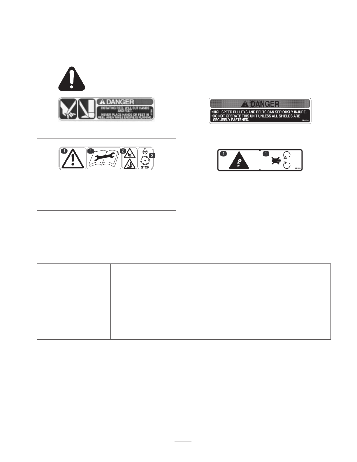
Safety and Instruction Decals
Safety decals and instructions are easily visible to the operator and are located near any
area of potential danger. Replace any decal that is damaged or lost.
Part No. 67-7960
Part No. 93-6688 (for CE)
1. Danger—read the
operator’s manual before
performing maintenance.
2. Cutting hazard to hands,
fingers, and feet—stop the
engine before going near
rotating reels.
Specifications
General Specifications
5 Blade—1 to 3 in. (25 to 76 mm)
Height-of-cut
Height-of-cut adjustment
7 Blade—1/2 to 1-3/4 in. (9.5 to 45 mm)
11 Blade—3/8 to 3/4 in. (9.5 to 19 mm)
Quick adjustment and positive locking is provided by locking type cone nuts.
Gauge marks of 1/4 in. (6.3 mm) are provided as a reference for easy changes of
height-of-cut.
Part No. 85-6410
Part No. 93-7814 (for CE)
1. Entanglement hazard—stay away from moving parts.
Clip (variable to match
cutting conditions)
5 Blade Cutting Unit: .176 in. per mph (.352 in. at 2 MPH-1.32 in. at 7.5 mph)
7 Blade Cutting Unit : .126 in. per mph (.252 in. at 2 MPH-.945 in. at 7.5 mph)
11 Blade Cutting Unit: .080 in. per mph (.16 in. at 2 MPH-.600 in. at 7.5mph)
3
Page 4

Optional Accessories
Floatation Kit (1 per machine) Model No. 03760
Fixed Head Kit (1 per machine) Model No. 03762
Wiehle Roller Kit (1 per machine) Model No. 03740
Side Skid Kit (1 per machine) Model No. 03744
Full Roller Kit (1 per machine) Model No. 03742
Dethatching Unit, RH
(3 per machine)
Dethatching Unit, LH
(2 per machine)
Rear Roller Scraper Kit
(1 per cutting unit)
Front Full Roller Scraper Kit
(1 per cutting unit)
Note: The front roller or other optional accessories for the
front of the cutting unit are shipped separately. Use the
instructions and parts supplied with the selected options
for installation on the cutting unit.
Model No. 03732
Model No. 03730
Part No. 59-6090
Part No. 62-6220
Assembly
Note: Determine the left and right sides of the machine from the normal operating position.
Loose Parts
Note: Use this chart as a checklist to ensure that all parts have been received. Without these parts, total setup cannot be
completed.
Description Qty. Use
Decals 2 Affix to cutting unit for CE.
Operator’s manual 1 Read before operating.
Parts catalog 1
Registration card 1 Fill out and return to Toro.
The following parts are required to mount the cutting
units:
• 3 Right-Hand Cutting Units
• 2 Left-Hand Cutting Units
• 1 Front Roller or Skid Kit
• 1 Floatation Kit (includes 3 Weights, 1 Backlapping
Brush, and 1 Gauge Bar) or
Important Thoroughly read both Cutting Unit and
Traction Unit Operator Manuals. Failure to do so may
result in damage to the cutting unit and/or poor
performance.
• 1 Fixed Head Kit (includes 3 Weights and 1
Backlapping Brush)
4
Page 5
Caution
If you leave the key in the ignition switch, someone could accidently start the engine and
seriously injure you or other bystanders.
Remove the key from the ignition before installing, servicing, or making adjustments to the
cutting units.
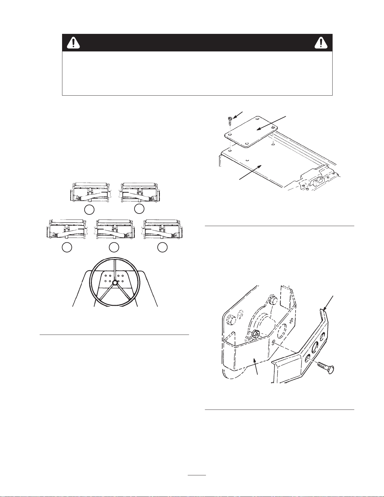
Installing the Tipper Plates and
Weights to the Cutting Units
1. Refer to Figure 1 and layout all five cutting units on
the floor in front of the machine. Position 3 right-hand
cutting units (all three are alike) as #1, #3 and #5.
Position the left-hand #2 and #4 cutting units also
(both are alike).
FRONT
2
1
3
54
3
1
Figure 2
1. Inboard cutting unit cover
2. Tipper plate
Note: Do not install a tipper plate on the #1 cutting unit.
4. Mount one weight to each cutting unit guard (Fig. 3)
on the #1, #2 and #3 cuttings. Weights are located at
the opposite end of each cutting unit drive housing.
Use 1/2 in. carriage bolts provided with weights
(Fig. 3).
2
3. Flathead socket capscrew
Figure 1
Cutting Unit Layout
2. Install a front roller or skid kit to each cutting unit.
Installation instructions and cutting unit guards are
included with each kit.
3. On the #2 and #3 cutting units, remove 4 cover
capscrews located at the outside end of the cutting unit
drive housing. Discard cover screws. Mount a tipper
plate to front left-hand (#2) cutting unit and the front
right-hand (#3) cutting unit using flathead socket
screws and locknuts supplied with tipper plates
(Fig. 2).
1
2
Figure 3
1. Weight 2. Guard
5. On the #4 and #5 cutting units, remove 4 cover
capscrews located at the outside end of the cutting unit
drive housing. Discard cover screws. Tipper brackets
will be mounted at these locations after the #4 and #5
cutting units are mounted on lift arms (Fig. 2).
5
Page 6
Installing the Floatation Kit
Mount a Flotation Kit Assembly (Fig. 4) to each cutting
unit with U-bolts, lock washers and nuts supplied with
kits. Male end of floatation assembly to be positioned
forward. Tighten U-bolts evenly.
Caution
2
1
Fingers can be pinched in the floatation u-joint.
Keep hands and fingers away from the u-joint.
Note: When installing floating head assembly to cutting
unit, make sure flap on bottom of assembly is positioned
to the inside of the cutting frame tubes (Fig. 4, inset).
1
2
6
5
3
1. Floatation kit assembly
2. U-bolts
3. Lift arm bolts
Figure 4
4. Flap
5. Capscrew and jam nut
6. Capscrew
4
5
4
Figure 5
1. Fixed head assembly
2. Thrust washer
(as required)
3. Cover plate
4. Attitude adjustment plate
5. Lift arm
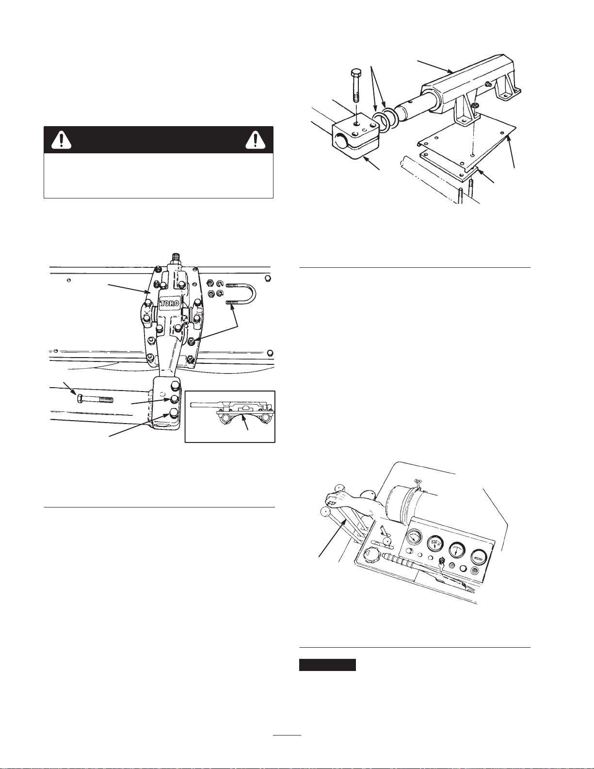
Securing the Cutting Units to
the Lift Arms
1. Remove three metric bolts from each of the lift arms
(Fig. 5).
Note: The smaller diameter bolt goes through both the
pivot arm and the lift arm. Keep these bolts separate.
2. With the parking brake on, start the traction unit and
adjust the engine to half throttle. Be sure to release the
lift arm lock lever for the #1, #2 and #3 cutting units
and put the reel lift control for the #1, #2 and #3
cutting units in the lower position (Fig. 6). Release the
lever and let it return to the neutral position.
3
Installing the Fixed Head Kit
Note: Before mounting each fixed head assembly to
cutting unit, insert the pivot arm of assembly into the
appropriate lift arm block, align mounting holes and
determine how many thrust washers (if any) are required
to fill gap between assembly body and lift arm block. Add
required amount of washers to pivot arm before installing
fixed head assembly to lift arm.
Mount a Fixed Head Kit Assembly (Fig. 5) to each cutting
unit with a cover plate, attitude adjustment plate, U-bolts,
lockwashers and nuts supplied with kits. Male end of
floatation assembly to be positioned forward. Tighten
U-bolts evenly.
1
Figure 6
1. Reel lift control
Important Do not allow lever to snap back into the
neutral position or the lift arms may not go into float.
6
Page 7

3. Stop the traction unit and remove the key. Manually
pull the lift arms, one at a time, to floor level. Repeat
this procedure for the #4 and #5 cutting units.
Caution
Without the cutting units installed, restarting the
engine will result in the lift arms raising.
Mount the Roller Bumpers
(Floatation Kit Only)
Note: Roller bumpers are required only when operating
cutting units in the float position and front rollers are
installed.
1. Locate mounting position of roller bumpers (Fig. 8) on
each side of frame tube in front of #1 cutting unit.
4. Roll the appropriate cutting unit to lift arm and match
the male end of pivot arm with hole in lift arm.
Note: It may be necessary to spread slotted block on lift
arm slightly to slide pivot arm fully into hole.
5. Reinstall 3 lift arm bolts but do not tighten (Fig. 5).
Mounting the #4 and #5 Tipper
Brackets
1. Loosely secure the hydraulic hoses to the underside of
each tipper bracket with hose clamps, spacers, clamp
plate, lock washers, and capscrew as shown in
Figure 7.
1
2
2. Loosely secure a roller bumper to each side of frame
tube, as shown in Figure 8, with U-bolts and locknuts.
3. Align the center of each bumper with the respective
end of the roller on the #1 cutting unit and tighten the
locknuts.
2
1
1
Figure 8
1. Roller bumpers 2. Frame tube
3
4
Figure 7
1. Tipper bracket
2. Hose clamp
2. Mount tipper brackets to cutting units with capscrews
and locknuts.
Important Raise and lower each cutting unit to ensure
that there is no binding of hoses during operation.
3. Tighten capscrews securing hose clamps to tipper
brackets.
3. Spacer
4. Clamp plate
7
Page 8

Mounting the Hydraulic Motors
to the Cutting Units
3. Insert the reel drive motor pulley through the housing
and slip the cutting unit drive belt over the pulley
(Fig. 11).
1. Remove locknuts, bolts, shipping cover, and drive
plate shield (Fig. 9) from the cutting unit.
2
1
Figure 9
1. Shipping cover 2. Drive plate shield
1
2
3
Figure 11
1. Hydraulic motor
2. Motor pulley
4. Insert the 2 reel drive motor mounting bolts (heads on
inside of the drive housing—flat washer on top bolt)
through the reel motor flange holes. Thread the
locknuts onto the bolts. Rotate reel motor upward in
the slotted hole in the housing to tension the drive belt
and tighten the fasteners (Fig. 12) to approx. 25 ft. lb.
(34 Nm).
Note: Proper belt tension is achieved when belt deflects
approximately 1/8 in. (3 mm) at mid-point when 7 lb. of
force is applied. (Fig. 12).
3. Drive belt
2. Discard shipping cover and install the drive plate
shield onto the reel drive motor flange (Fig. 10). Be
sure the widest portion of the shield is at the top.
2
1
Figure 10
1. Drive plate shield 2. Reel drive motor flange
Note: Check to see that motor pulley set screws are tight
on motor shaft before installing motor onto cutting unit
(Fig. 11).
1
Figure 12
1. Reel motor fasteners
Important Rotate motors by hand only. Never place a
bar between hose fittings on hydraulic motors—motor
damage may result.
5. Install the gasket and drive housing cover after making
sure the ends of the gasket are at the bottom of the
housing to allow for drainage.
Important When hydraulic motors have been mounted
to the cutting units, make sure hydraulic hoses lay flat and
do not contact the frame of the machine when the cutting
units are in the raised position. There should also be
sufficient slack so hoses are above and not in contact with
the floatation kit. If hoses appear twisted once the
8
Page 9

hydraulic motors have been mounted and the belts
tightened, loosen swivel nuts at the motor and reposition
hoses. This can greatly increase the life of the hoses. With
cutting units down, all cutting unit hoses should have a
flat natural lay and be free from twist.
6. Tighten tipper bracket clamps on #4 and #5 cutting
units (Fig. 7).
Note: Refer to the Traction Unit Operator ’s Manual for
instructions on setting the adjustable hydraulic
counterbalance, if so equipped.
3. If there is excessive contact, turn the adjusting knobs
counterclockwise until no contact is noticed. Then
equally turn both adjusting knobs clockwise, until light
contact is felt and heard between the reel and
bedknife. Final adjustment should always be in the
tightening (clockwise) direction.
4. Tighten adjuster locking nuts when completed making
adjustments.
Caution
Caution
Before adjusting reel to bedknife, raise and fully
latch cutting units. Remove key from the ignition
switch. Keep others off machine while adjusting
cutting units.
Adjusting the Reel to Bedknife
Contact
Before adjusting height-of-cut and each day before
operating, check reel to bedknife contact, regardless if
quality of cut had previously been acceptable.
Note: A 3/4 in. wrench is required for making the reel to
bedknife adjustment.
1. Slowly and carefully rotate the reel, listening for light
contact across the full length of the reel and bedknife.
2. If there is no contact, loosen the adjuster locking nut
on each adjuster (Fig. 13). Then, equally turn each
adjuster knob clockwise until light contact is felt and
heard.
2
Sharp edges on the cutting units can cut or pinch
hands or fingers.
• When adjusting the cutting units, wear heavy
gloves.
• Use care when turning the reels by hand.
Important Adjusted correctly, the reel will cut paper
(approx. .03 in. thick) across its entire length.
The cutting units will provide optimum mowing
performance when adjusted and maintained correctly.
Keeping a precise reel to bedknife adjustment (light
contact), at each end of the cutting unit will produce a
continual self-sharpening action. Therefore, sharp cutting
edges are maintained, good quality of cut ensured, and the
need for corrective re-sharpening reduced.
Important Cutting units with excessive contact
between the reel and bedknife are noisy, consume
excessive power, shorten component life and result in
overall poor performance. Light contact between the reel
and bedknife, once the cutting unit is warmed up, provides
optimum mowing performance and component life.
Adjusting the Height-of-Cut for
a Floating Cutting Unit
1
Figure 13
1. Adjuster locking nut 2. Adjustment knob
Adjusting the Reel to Bedknife Contact
Adjust reel to bedknife contact on all cutting units. Refer
to Adjusting the Reel to Bedknife Contact, page 9.
Leveling the Rear Roller to the Reel
1. Start engine and lower the cutting units onto a flat
surface such as a piece of 3/4 in. or 1 in. plywood (at
least 20 in. x 30 in. in size). Stop engine and remove
key from switch. Lock cutting units in the fixed
position, by loosening the jam nut on lockout pin
(Fig. 14) and screwing pin into hole in pivot arm
(Fig. 15). Tighten nut to secure lockout. Raise the
front rollers up so they do not contact the flat surface.
9
Page 10

1
2
Figure 14
Cutting Unit Float Position
1. Lockout pin 2. Jam nut
2. Insert a piece of bar stock 25–28 in. (70 cm) long
(Fig. 16), and approximately 3/8 in. (9.5 mm) thicker
than the desired height-of-cut, under the reel and up
against the bedknife cutting edge (Fig. 16). The reel
(not bedknife) must contact the bar stock along its full
length.
Note: Using a bar 3/8 in. (9.5 mm) thicker than
height-of-cut provides proper bedknife attitude (heeled
“up” in back) required for excellent low height-of-cut
performance.
contact after the jam nuts have been tightened. Check
roller contact by trying to slide paper between the
roller and the flat surface.
3/8
Figure 16
Leveling the Rear Roller to the Reel
4. Rear roller is now leveled to the reel.
Adjusting the Final Height-of-Cut Using
the Gauge Bar
1 2
Figure 15
Cutting Unit Fixed Position
1. Lockout pin 2. Jam nut
3. Loosen rear roller jam nuts and adjusting knobs and
push roller down against flat surface. At this point the
reel should be contacting the bar stock and the rear
roller contacting the flat surface. Contact should exist
along the entire length of the reel and rear roller.
Tighten rear roller adjustment knobs and jam nuts.
Recheck to be sure roller and reel are both still making
1. Raise cutting units and lock in the transport position.
Shut off the engine and remove the key.
2. Use gauge bar (Toro Part No. 98-1852) to set final
height-of-cut by adjusting front roller only.
Note: Position long cone nut (Fig. 17) on bottom for
heights of 1-1/4 in. or higher. Position short cone nut on
bottom for heights of below 1-1/4 in.
10
Page 11

2
1
Figure 17
1. Long cone nut 2. Short cone nut
3. Loosen the gauge bar jam nut and adjust the first
screw to set dimension between underside of screw
head and gauge bar for desired height-of-cut. (Fig. 18).
Tighten the jam nut to secure the adjustment. Hook
screw head over cutting edge of bedknife and position
bar against bottom of front roller (Fig. 19).
4. Loosen front roller nuts and adjust both ends of the
front roller until it contacts gauge bar at both ends.
With the gauge bar held firmly against the bottom of
the rollers, adjust the front roller so the screw head just
slips over the lip of the bedknife (Fig. 19). Tighten the
front roller nuts.
98-1852
Figure 19
Final Height-of-Cut Adjustment Using Gauge Bar
Important When set properly, the front and rear
rollers will contact the gauge bar and the screw head will
be snug over the bedknife cutting edge when checked at
both ends of the reel.
98-1852
Figure 18
Gauge Bar Assembly
5. Loosen lockout pin so cutting unit can float freely
(Fig. 14).
Quick Method for Changing
Height-of-Cut after Initial Setup
of a Floating Cutting Unit
If the reel to bedknife adjustment has been set and the rear
roller leveled to the reel, the cutting unit may be quickly
changed from one height-of-cut to another by using the
gauge bar (Part No. 98-1852) and adjusting the front roller
only. In many cases, an entire machine can be done
quickly by using the gauge bar to set the front roller of
one cutting unit. The remaining cutting units can then be
set by loosening their front roller jam nuts and turning
each front roller adjustment knob the same number of
turns and in the same direction as the first unit.
11
Page 12

Checking/Adjusting the
Cutting Unit Attitude
1. Place an angle indicator, Toro Part No. 99-3503, on the
bedknife and record the bedknife angle (Fig. 20).
1
3
1
2
1. First screw
2. Second screw
4
Figure 21
3. Gauge bar angle
4. Front roller
Figure 20
1. Bedknife angle
2. Using a two-screw gauge bar, Toro Part No. 98-1852,
set the first screw to the desired height-of-cut.
3. Place the gauge bar across the front and rear rollers.
The first screw head needs to fit snugly over the edge
of the bedknife while the gauge bar contacts the rollers
(Fig. 21).
4. Adjust the second screw to contact the bedknife.
5. Place an angle indicator on the gauge bar and record
the gauge bar angle (Fig. 21).
6. Bedknife Angle (step 1) – Gauge Bar Angle (step 5) =
Cutting Unit Attitude (degrees)
7. For adjusting the cutting unit attitude, adjust the
second screw for the desired attitude, then repeat the
height-of-cut adjustment for a floating cutting unit;
refer to Leveling the Rear Roller to the Reel, page 9.
Change the bar stock thickness for leveling the rear
roller in order to accommodate your desired cutting
unit attitude.
12
Page 13

Height-of-Cut Adjustment for a
Fixed Cutting Unit
1. Adjust reel to bedknife contact.
2. Loosen nuts securing skids or front roller and raise to
highest position.
3. Loosen jam nuts securing rear roller. Lower roller
beyond desired height-of-cut (ensures proper bedknife
attitude).
4. Lower cutting unit onto a flat surface, such as a 1 in. x
20 in. x 30 in. piece of plywood. Shut off engine and
remove the key.
5. Insert piece of bar stock (Fig. 16) 25–28 in. (70 cm)
long with thickness equal to desired height-of-cut,
under entire length of the reel, next to bedknife.
6. Adjust rear roller adjustment knobs and jam nuts until
full length of the rear roller contacts the flat surface
and the full length of the reel (not bedknife) contacts
the bar stock. Tighten rear roller knobs and jam nuts.
Adjusting the Skids and Front
Maintenance
Note: Determine the left and right sides of the machine
from the normal operating position.
Lubrication
Before and after greasing, wipe each grease fitting with a
clean rag. Use a hand-operated grease gun and #2 general
purpose grease to lubricate the eight grease fittings.
Applying too much pressure will ruin the seals and
leaking grease could cause damage to grass.
Important Before washing the machine, shut off the
engine and remove the key. Lubricate the reels and rollers
immediately after washing the machine. This helps to
minimize water entering the reel and roller bearings.
Roller (Fixed Head Kit)
After skid kit or front rollers are installed (installation
instructions are included with each option) make the
following adjustments to prevent them from pushing down
uncut grass or scalping on undulating terrain:
1. Lock each cutting unit in the fixed position (Refer to
Cutting Unit Orientation, Fig. 15). Set the reel to
bedknife adjustment and height-of-cut adjustment.
2. Position the cutting units on a flat, level surface (1 in.
(25 mm) thick piece of plywood).
3. Skids and front rollers used to prevent scalping should
not ride on the ground. Adjust each skid or front roller
so it is 1/8–1/4 in. (3–6 mm) or higher above the level
surface. Allow greater clearance at the higher
height-of-cut settings.
4. Proper adjustment is achieved when the cutting unit
does not scalp the grass in normal mowing conditions
and yet is set high enough not to mar the turf and
create undue wear on the skids or rollers.
Note: Skids are used only with the cutting unit in the
fixed position. Front rollers may be used with the cutting
unit in either the fixed or floating position.
Figure 22
Important If the cutting units are washed in the raised
position, be sure to lower them to the ground after
washing. This allows water to drain from the ends of the
rollers and reel bearing housings.
1. Lubricate the reel shaft and roller bearings with 3 or 4
pumps of grease. Daily lubrication of these fittings
purges water and other contaminants, increasing
service life and maintaining excellent quality-of-cut.
Note: When greasing roller bearings, grease forced from
bearings will not be visible around the roller shaft.
13
Page 14

Figure 23
starting the engine raise the grass deflector on the #1
cutting unit (center) and tighten fasteners to retain the
deflector in the raised position.
Operator Duties
1. Sit on the seat and engage parking brake.
2. Turn reel speed knob counterclockwise to slowest (#1)
position.
3. Start the engine and run at minimum throttle. Lower
either:
• The center 3 cutting units (#1, 2 & 3 ) or
2. Lubricate the floatation kit pivots and fixed head kit
pivots with one pump of grease weekly.
Figure 24
Backlapping
Danger
During the backlap operation the reels are under
power. Contact with rotating reels can result in
personal injury.
• Do not adjust the cutting units while the engine
and reels are operating.
• Instruct the operator to stop the reels and shut
the engine off when an adjustment is necessary.
• Left-hand (#4) cutting unit or
• Right-hand (#5) cutting unit
The center 3 cutting units run and shut off together.
With the #4 & #5 cutting units up and latched
(automatically shut off) and the #1, #2 & #3 cutting
units down, backlap the center (#1) cutting unit from
the rear of the machine with the long handled brush.
Backlap the #2 and #3 cutting units from the front of
the machine.
4. Wait for second person’s instruction to engage reels in
backlap mode. Pull up on control lever and turn the
reel speed knob counterclockwise to the backlap
position.
5. Follow the second person’s instructions. Be prepared
to stop reels and engine quickly in case of an
emergency.
Duties for Second Person
1. Instruct operator when to start and stop reels.
Danger
Contact with the reel or other moving parts can
result in personal injury.
• Stay away from the reel while backlapping.
• Never use a short handled paint brush to apply
backlapping compound.
Use a good grade of medium grit (80 courseness) lapping
compound with a water soluble carrier so the compound
will be easily washed away after completion of the
operation. Dry lapping compound should be mixed with
liquid detergent until it has a free-flowing consistency.
Two people are required to perform backlapping. Good
communication between one another is necessary and
caution should be used when making each move. With one
person on the seat to operate the controls (operator) the
other performs the backlapping operation. Note: Before
2. Dip 3 in. (76 mm) paint brush attached to Toro Part
No. 29-9200 Handle Assembly into lapping
compound. Stand clear and instruct operator to engage
reel into backlap mode.
3. Apply lapping compound evenly over full length of the
reel, ensuring that all reel blades are covered.
Whenever noise of reel against the bedknife begins to
disappear or, an uneven concentration of material
appears on the reel, redistribute the compound with the
brush.
14
Page 15

4. When it becomes necessary to adjust the reel to the
bedknife, instruct the operator to disengage the reel,
stop the engine and remove the key from the ignition
switch. Then proceed with the adjustment only after
the reels have stopped rotating.
5. Backlap each reel until the cutting edges are sharp,
even, and consistent on all blades. Achieve a minimum
of 1/32 in. (0.79 mm) land area on newly sharpened
reel assemblies. Normally, a reel need only be
backlapped for approximately 3 minutes.
3
2
6. Upon completion, stop the reel and turn off the engine.
Remove the key from the ignition switch. Wash the
unit thoroughly with a low pressure stream of water to
remove all lapping material. Allow the reel to dry and
lubricate the grease fittings.
7. Check sharpness of the reel and bedknife with strips of
newspaper. With light reel to bedknife contact, the
paper should be cleanly sheared across the entire width
of the reel. If the paper is not sheared acceptably,
continue backlapping.
8. After backlapping the #1, #2 and #3 cutting units, raise
and latch these units and proceed with the #4 and #5
cutting units.
Note: See the Toro Sharpening Manual (Part No. 80-300)
for additional backlapping/sharpening information.
Servicing the Bedknife/Bedbar
Note: The bedbar on each cutting unit has a precision
ground mounting surface to provide an excellent fit with a
bedknife. Backlapping of replacement bedknives is often
sufficient to achieve an excellent cutting edge with
minimum material removed.
1
Figure 25
1. Shoulder bolts (2 each
side)
2. Bushing
3. Spacer
2. Remove the mounting screws for the bedknife and
separate the bedknife from the bar (Fig. 26). Discard
the screws.
1
Removing the Bedknife/Bedbar
1. Remove the shoulder bolts, bushings, and spacers from
each end of the unit and remove the bedbar/bedknife
assembly (Fig. 25).
3
1. Bedbar
2. Bedknife
3. Bedknife mounting screws
15
2
Figure 26
4. Bedknife mounting
4
components
Page 16

Installing the Bedknife/Bedbar
1. Thoroughly clean the bedknife mounting face on the
bedbar of all rust and scale. Remove any material on
the mounting face of the bedbar that will affect a good
match-up with the bedknife.
2. Before installation, apply a coating of Never Seez, or
any material that will ease future disassembly of the
bedknife mounting screws to the threads before
installation.
3. Use a torque wrench and Part No. 51-0880 special tool
to finish tightening the screws (Fig. 27). Torque the
screws to 250 in.-lb. (28 Kgm) beginning with the
center screw and tightening alternate screws toward
each end to ensure that the bedknife will be flat
against the bedbar.
4
3
1
4. Install the bedbar/bedknife assembly to the cutting
unit.
1
2
3
Figure 27
1. Torque wrench
2. Tool—Toro Part No.
51-0880
3. T orque from center out
1
2
Figure 28
1. Guard
2. Mounting fasteners
3. Bedbar mounting
assembly
4. Adjusting assembly
5. Dust cap
2. Remove the shoulder bolts, bushings, and spacers from
each end of the unit and remove the bedbar/bedknife
assembly (Fig. 29).
3. Remove the inboard locknut from the adjuster pin, the
fasteners for the bracket, and the adjusting handle
assembly from the sideplate (Fig. 29).
5
6
Servicing the Reel Assembly
Removing the Reel Assembly
1. Remove the guards from each end of the cutting unit
and the front and rear roller assemblies (Fig. 28).
1. Locknut
2. Belleville washer
3. Shoulder bolt
16
2
4
1
3
Figure 29
4. Bearing housing
5. Reel shaft
6. Flange bushings
Page 17

4. Disassemble the cone nut from the shoulder bolt
securing the bearing housing to the sideplate, remove
the Belleville washer and bolt, and slide the bearing
housing off of the reel shaft (Fig. 30).
5. Remove the cover from the drive housing and remove
the drive belt from the housing (Fig. 30).
1
6
5
4
2
2
Figure 30
1. Drive housing (cover
removed)
2. Drive Belt
6. Remove the reel capscrew, toothed washer, and pulley
washer from the reel shaft (Fig. 31).
Note: The capscrew is assembled with a thread locking
compound.
7
1
3
Figure 31
1. Reel capscrew
2. Pulley washer
3. Driven pulley
4. Drive housing
5. Adjusting handle
assembly
6. Woodruff key
7. Drive housing fasteners
7. Using a puller, remove the driven pulley from the reel
shaft (Fig. 31). Remove the woodruff key from the reel
shaft.
8. Remove the adjustment assembly and cone nut,
Belleville washer, and shoulder bolt securing the
housing to the sideplate (Fig. 31). Remove the
housing.
9. Slide the reel assembly out of the slots in the
sideplates.
10.To remove the bearing and seals from the drive
housing, remove the retaining ring from the inside of
the housing. Pry the outer seal out of the belt drive
case side. Press the bearing and rear seal out from the
outer side of the housing.
11. To remove the bearing and seal from the bearing
housing, remove the dust cap (Fig. 28) and press the
bearing and seal out of the housing.
17
Page 18

Installing the Reel Assembly
1. Inspect the flange bushings in the mounting holes for
the drive housing and bearing housing for wear
(Fig. 29). Replace, if necessary.
2. Assemble the outer seal (lip facing in to retain grease)
into the drive housing using Loctite 242 retaining
compound on the outer diameter. Apply a light coat of
oil to the seal lips and insert the bearing assembly
through the seal from the opposite side (Fig. 32).
Figure 32
3. Apply a light coating of oil to the inner seal lips and
install (lip facing away from the bearing and toward
the reel) in the housing. Install the retaining ring to
secure the assembly in the housing (Fig. 32).
10.Ensure the slot in the pulley washer is aligned with the
roll pin in the pulley and install the washer, toothed
washer, and reel capscrew (Fig. 31). Apply a medium
strength thread locking compound to the reel capscrew
during assembly. Torque the capscrew to 45–55 ft.-lb.
11. Install the reel adjustment assemblies to each
sideplate. Install roll pins before tightening fasteners.
12.Install the bedbar/bedknife assembly.
13.Install the front and rear roller assemblies or skids.
14.Adjust the reel to the bedknife; refer to Adjusting the
Reel to the Bedknife, page 9. Adjust the
height-of-cut; refer to Adjusting the Height-of-Cut,
page 9.
Removing the Roller
The roller assemblies can be removed by the following
methods:
1. Remove the fasteners securing the guard and roller
adjustment housing to the side plate (Fig. 33) or
unscrew the upper cone nut and drop the threaded rod
out of the adjustment housing (Fig. 34).
4. Apply a light coat of oil to the seal lips of the seal for
the bearing housing and install (lip facing away from
the bearing) over the bearing assembly (Fig. 32).
5. Insert the bearing and seal in the housing and install
the dust cap into the housing.
6. Assemble the reel assembly to the frame. Ensure the
shield washer is installed on the drive housing end of
the reel shaft. Align the drive pin on reel shaft with the
slot in the bearing and slide the drive housing onto the
shaft.
7. Insert the shoulder bolt through the Belleville washer
and rear housing mounting hole. Slide the bolt through
the sideplate mounting hole (Fig. 29). Install the cone
nut locknut onto the bolt. Tighten the cone nut to
45–55 ft.-lb.
8. Align the drive pin on the reel shaft with the notch in
the bearing inner race and slide the bearing housing
over the opposite end of the reel shaft. Insert the
shoulder bolt and Belleville washer through the rear
bearing housing mounting hole. Slide the bolt through
the sideplate mounting hole. Install the cone onto the
bolt. Tighten the cone nut to 45–55 ft.-lb.
9. Install the woodruff key in the drive housing end of the
reel shaft and install the driven pulley onto the shaft.
2
1
1. Guard
2. Roller adjusting housing
3
4
Figure 33
3. Sideplate
4. Mounting fasteners
18
Page 19

2
3
1
Figure 34
1. Cone nut
2. Rod and collar assembly
2. The threaded rod and collar assembly can be removed
from the roller by sliding it off the shaft at both ends
(Fig. 34).
3. Flex locknut
Installing the Roller
Important When assembling a new roller to the
cutting unit, mount the roller so that the roller shaft
locknut is on the right side of the cutting unit (Fig. 34) (as
viewed by the operator sitting on the seat of the machine).
This prevents the locknut from loosening during
operation.
19
Page 20

The Toro General Commercial Products Warranty
A Two-Year Limited Warranty
Conditions and Products Covered
The Toro Company and its affiliate, Toro Warranty Company,
pursuant to an agreement between them, jointly warrant your Toro
Commercial Product (“Product”) to be free from defects in
materials or workmanship for two years or 1500 operational
hours*, whichever occurs first. Where a warrantable condition
exists, we will repair the Product at no cost to you including
diagnosis, labor, parts, and transportation. This warranty begins
on the date the Product is delivered to the original retail purchaser.
* Product equipped with hour meter
Instructions for Obtaining Warranty Service
You are responsible for notifying the Commercial Products
Distributor or Authorized Commercial Products Dealer from whom
you purchased the Product as soon as you believe a warrantable
condition exists.
If you need help locating a Commercial Products Distributor or
Authorized Dealer, or if you have questions regarding your
warranty rights or responsibilities, you may contact us at:
Toro Commercial Products Service Department
Toro Warranty Company
8111 Lyndale Avenue South
Bloomington, MN 55420-1196
952-888-8801 or 800-982-2740
E-mail: commercial.service@toro.com
Owner Responsibilities
As the Product owner, you are responsible for required maintenance and adjustments stated in your operator’s manual. Failure
to perform required maintenance and adjustments can be grounds
for disallowing a warranty claim.
Items and Conditions Not Covered
Not all product failures or malfunctions that occur during the
warranty period are defects in materials or workmanship. This
express warranty does not cover the following:
• Product failures which result from the use of non-Toro
replacement parts, or from installation and use of add-on,
modified, or unapproved accessories
• Product failures which result from failure to perform required
maintenance and/or adjustments
• Product failures which result from operating the Product in an
abusive, negligent or reckless manner
• Parts subject to consumption through use unless found to be
defective. Examples of parts which are consumed, or used up,
during normal Product operation include, but are not limited to,
blades, reels, bedknives, tines, spark plugs, castor wheels,
tires, filters, belts, etc.
• Failures caused by outside influence. Items considered to be
outside influence include, but are not limited to, weather,
storage practices, contamination, use of unapproved coolants,
lubricants, additives, or chemicals, etc.
• Normal “wear and tear” items. Normal “wear and tear”
includes, but is not limited to, damage to seats due to wear or
abrasion, worn painted surfaces, scratched decals or windows, etc.
Parts
Parts scheduled for replacement as required maintenance are
warranted for the period of time up to the scheduled replacement
time for that part.
Parts replaced under this warranty become the property of Toro.
Toro will make the final decision whether to repair any existing part
or assembly or replace it. Toro may use factory remanufactured
parts rather than new parts for some warranty repairs.
General Conditions
Repair by an Authorized Toro Distributor or Dealer is your sole
remedy under this warranty.
Neither The Toro Company nor Toro Warranty Company is
liable for indirect, incidental or consequential damages in
connection with the use of the Toro Products covered by this
warranty, including any cost or expense of providing substitute equipment or service during reasonable periods of
malfunction or non-use pending completion of repairs under
this warranty . Except for the Emissions warranty referenced
below, if applicable, there is no other express warranty. All
implied warranties of merchantability and fitness for use are
limited to the duration of this express warranty.
Some states d o n o t a l l o w exclusions of incidental or consequential
damages, or limitations on how long an implied warranty lasts, so
the above exclusions and limitations may not apply to you.
This warranty gives you specific legal rights, and you may also
have other rights which vary from state to state.
Note regarding engine warranty: The Emissions Control
System on your Product may be covered by a separate warranty
meeting requirements established by the U.S. Environmental
Protection Agency (EPA) and/or the California Air Resources
Board (CARB). The hour limitations set forth above do not apply to
the Emissions Control System Warranty. Refer to the Engine
Emission Control Warranty Statement printed in your operator’s
manual or contained in the engine manufacturer’s documentation
for details.
Countries Other than the United States or Canada
Customers who have purchased Toro products exported from the United States or Canada should contact their Toro Distributor (Dealer)
to obtain guarantee policies for your country , province, or state. If for any reason you are dissatisfied with your Distributor’s service or
have difficulty obtaining guarantee information, contact the Toro importer. If all other remedies fail, you may contact us at Toro Warranty
Company.
Part No. 374-0031 Rev. a
 Loading...