

Page 1

FormNo.3374-295RevC
Reelmaster
®
7000-D4-Wheel
DriveTractionUnit
ModelNo.03708N—SerialNo.313000001andUp
ToregisteryourproductordownloadanOperator'sManualorPartsCatalogatnocharge,gotowww.T oro.com.OriginalInstructions(EN)
Page 2
WARNING
CALIFORNIA
Proposition65Warning
Dieselengineexhaustandsomeofits
constituentsareknowntotheStateof
Californiatocausecancer,birthdefects,
andotherreproductiveharm.
Becauseinsomeareastherearelocal,state,orfederal
regulationsrequiringthatasparkarresterbeusedonthe
engineofthismachine,asparkarresterisincorporated
withthemuferassembly.
GenuineTorosparkarrestersareapprovedbytheUSDA
ForestryService.
Important:Thisengineisequippedwithaspark
arrestermufer.ItisaviolationofCaliforniaPublic
ResourceCodeSection4442touseoroperate
theengineonanyforest-covered,brush-covered,
orgrass-coveredlandwithoutasparkarrester
mufermaintainedinworkingorder,ortheengine
constricted,equipped,andmaintainedforthe
preventionofre.Otherstatesorfederalareasmay
havesimilarlaws.
Wheneveryouneedservice,genuineToroparts,
oradditionalinformation,contactanAuthorized
ServiceDealerorToroCustomerServiceandhave
themodelandserialnumbersofyourproductready.
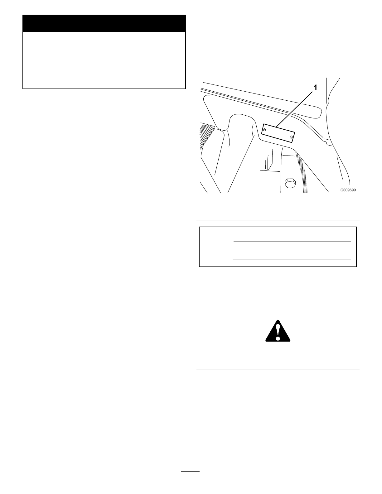
Figure1identiesthelocationofthemodelandserial
numbersontherightfrontframememberofthe
product.Writethenumbersinthespaceprovided.
Figure1
1.Modelandserialnumberlocation
Theenclosed
Engine Owner's Man ual
issupplied
forinformationregardingtheUSEnvironmental
ProtectionAgency(EPA)andtheCalifornia
EmissionControlRegulationofemissionsystems,
maintenance,andwarranty.Replacementsmaybe
orderedthroughtheenginemanufacturer.
Introduction
Thismachineisaride-on,reel-bladelawnmower
intendedtobeusedbyprofessional,hiredoperatorsin
commercialapplications.Itisprimarilydesignedfor
cuttinggrassonwell-maintainedlawnsingolfcourses,
parks,sportselds,andoncommercialgrounds.Itis
notdesignedforcuttingbrush,mowinggrassandother
growthalongsidehighways,orforagriculturaluses.
Readthisinformationcarefullytolearnhowtooperate
andmaintainyourproductproperlyandtoavoidinjury
andproductdamage.Youareresponsibleforoperating
theproductproperlyandsafely.
ModelNo.
SerialNo.
Thismanualidentiespotentialhazardsandhassafety
messagesidentiedbythesafetyalertsymbol(
Figure2),
whichsignalsahazardthatmaycauseseriousinjury
ordeathifyoudonotfollowtherecommended
precautions.
Figure2
1.Safetyalertsymbol.
Thismanualusestwootherwordstohighlight
information.Importantcallsattentiontospecial
mechanicalinformationandNoteemphasizesgeneral
informationworthyofspecialattention.
YoumaycontactTorodirectlyatwww .Toro.comfor
productandaccessoryinformation,helpndingadealer,
ortoregisteryourproduct.
©2013—TheT oro®Company
8111LyndaleAvenueSouth
Bloomington,MN55420
Contactusatwww.Toro.com.
2
PrintedintheUSA.
AllRightsReserved
Page 3

Contents
Introduction.................................................................2
Safety...........................................................................4
SafeOperatingPractices.......................................4
ToroRidingMowerSafety....................................6
SafetyandInstructionalDecals.............................7
Setup.........................................................................11
1AdjustingtheSupportRollers...........................12
2InstallingtheCuttingUnits..............................12
3AdjustingtheTurfCompensation
Spring............................................................15
4UsingtheCuttingUnitKickstand.....................16
5GreasingtheMachine......................................16
6CheckingFluidLevels......................................17
ProductOverview......................................................17
Controls.............................................................17
Specications.....................................................21
TractionUnitSpecications................................21
Attachments/Accessories...................................21
Operation...................................................................22
CheckingtheEngineOilLevel............................22
CheckingtheCoolingSystem..............................23
FillingtheFuelTank...........................................23
CheckingtheHydraulicFluidLevel.....................25
CheckingtheTirePressure.................................26
StartingandStoppingtheEngine........................26
CheckingtheInterlockSwitches.........................26
SettingtheReelSpeed.........................................27
AdjustingtheLiftArmCounterbalance...............28
AdjustingtheLiftArmTurnAround
Position..........................................................28
PushingorTowingtheMachine..........................29
JackingPoints.....................................................29
TieDowns.........................................................29
UnderstandingtheDiagnosticLight....................29
DiagnosticAceDisplay.......................................30
CheckingtheInterlockSwitches.........................30
OperatingCharacteristics...................................31
EngineCoolingFanOperation...........................32
OperatingTips...................................................32
Maintenance...............................................................33
RecommendedMaintenanceSchedule(s)................33
DailyMaintenanceChecklist...............................34
ServiceIntervalChart.........................................35
PremaintenanceProcedures....................................36
RemovingtheHood...........................................36
Lubrication.............................................................36
GreasingtheBearingsandBushings....................36
EngineMaintenance...............................................38
ServicingtheAirCleaner....................................38
ServicingtheEngineOilandFilter......................39
AdjustingtheThrottle........................................39
FuelSystemMaintenance.......................................40
FuelTank...........................................................40
FuelLinesandConnections................................40
ServicingtheWaterSeparator.............................40
FuelPickupTubeScreen....................................40
BleedingAirfromtheInjectors...........................41
ElectricalSystemMaintenance................................41
ChargingandConnectingtheBattery..................41
BatteryCare.......................................................42
Fuses..................................................................43
DriveSystemMaintenance.....................................44
CheckingtheTorqueoftheWheel
Nuts...............................................................44
CheckingthePlanetaryGearDrive
Oil..................................................................44
ChangingthePlanetaryGearDrive
Oil..................................................................44
CheckingtheRearAxleLubricant.......................45
ChangingtheRearAxleLubricant.......................45
AdjustingtheTractionDriveforNeutral.............46
CheckingtheRearWheelT oe-In.........................46
CoolingSystemMaintenance..................................47
ServicingtheEngineCoolingSystem..................47
BrakeMaintenance.................................................48
AdjustingtheServiceBrakes...............................48
BeltMaintenance....................................................48
ServicingtheAlternatorBelt...............................48
HydraulicSystemMaintenance...............................49
ChangingtheHydraulicFluid.............................49
ReplacingtheHydraulicFilters...........................49
CheckingtheHydraulicLinesandHoses.............50
CuttingUnitMaintenance.......................................50
BacklappingtheCuttingUnits............................50
Cleaning.................................................................51
ServicingtheSparkArrestorMufer...................51
Storage.......................................................................52
Engine...............................................................52
TractionUnit......................................................52
Schematics.................................................................53
3
Page 4

Safety
ThismachinemeetsorexceedsANSIB71.4-2004
specicationsineffectatthetimeofproduction.
Improperuseormaintenancebytheoperatoror
ownercanresultininjury.T oreducethepotential
forinjury,complywiththesesafetyinstructions
andalwayspayattentiontothesafetyalertsymbol,
whichmeansCAUTION,WARNING,orDANGER"personalsafetyinstruction."Failuretocomplywiththe
instructionmayresultinpersonalinjuryordeath.
SafeOperatingPractices
ThefollowinginstructionsarefromtheCENstandard
EN836:1997,ISOstandard5395:1990,andANSI
B71.4-2004.
Training
•Readtheoperator'smanualandothertraining
materialcarefully .Befamiliarwiththecontrols,
safetysigns,andtheproperuseoftheequipment.
•Neverallowchildrenorpeopleunfamiliarwiththese
instructionstouseorservicethemower.Local
regulationsmayrestricttheageoftheoperator.
•Nevermowwhilepeople,especiallychildren,orpets
arenearby .
•Keepinmindthattheoperatororuserisresponsible
foraccidentsorhazardsoccurringtootherpeopleor
theirproperty.
•Donotcarrypassengers.
•Alldriversandmechanicsshouldseekandobtain
professionalandpracticalinstruction.Theowneris
responsiblefortrainingtheusers.Suchinstruction
shouldemphasize:
–theneedforcareandconcentrationwhen
workingwithride-onmachines;
–controlofaride-onmachineslidingonaslope
willnotberegainedbytheapplicationofthe
brake.Themainreasonsforlossofcontrolare:
◊insufcientwheelgrip;
◊beingdriventoofast;
◊inadequatebraking;
◊thetypeofmachineisunsuitableforitstask;
◊lackofawarenessoftheeffectofground
conditions,especiallyslopes;
◊incorrecthitchingandloaddistribution.
•Theowner/usercanpreventandisresponsiblefor
accidentsorinjuriesoccurringtohimselforherself,
otherpeople,orproperty.
Preparation
•Whilemowing,alwayswearsubstantialfootwear,
longtrousers,hardhat,safetyglasses,andear
protection.Longhair,looseclothing,orjewelrymay
gettangledinmovingparts.Donotoperatethe
equipmentwhenbarefootorwearingopensandals.
•Thoroughlyinspecttheareawheretheequipment
istobeusedandremoveallobjectswhichmaybe
thrownbythemachine.
•Warning—Fuelishighlyammable.Takethe
followingprecautions:
–Storefuelincontainersspecicallydesignedfor
thispurpose.
–Refueloutdoorsonlyanddonotsmokewhile
refuelling.
–Addfuelbeforestartingtheengine.Never
removethecapofthefueltankoraddfuelwhile
theengineisrunningorwhentheengineishot.
–Iffuelisspilled,donotattempttostartthe
enginebutmovethemachineawayfromthe
areaofspillageandavoidcreatinganysourceof
ignitionuntilfuelvaporshavedissipated.
–Replaceallfueltanksandcontainercapssecurely.
•Replacefaultysilencers/mufers.
•Evaluatetheterraintodeterminewhataccessories
andattachmentsareneededtoproperlyand
safelyperformthejob.Onlyuseaccessoriesand
attachmentsapprovedbythemanufacturer.
•Checkthattheoperator'spresencecontrols,safety
switchesandshieldsareattachedandfunctioning
properly.Donotoperateunlesstheyarefunctioning
properly.
Operation
•Donotoperatetheengineinaconnedspacewhere
dangerouscarbonmonoxidefumescancollect.
•Mowonlyindaylightoringoodarticiallight.
•Beforeattemptingtostarttheengine,disengageall
bladeattachmentclutches,shiftintoneutral,and
engagetheparkingbrake.
•Rememberthereisnosuchthingasasafeslope.
Travelongrassslopesrequiresparticularcare.To
guardagainstoverturning:
–donotstoporstartsuddenlywhengoingupor
downhill;
–machinespeedsshouldbekeptlowonslopes
andduringtightturns;
–stayalertforhumpsandhollowsandother
hiddenhazards;
4
Page 5

–Donotturnsharply.Usecarewhenreversing.
–Usecounterweight(s)orwheelweightswhen
suggestedintheoperator'smanual.
•Stayalertforholesintheterrainandotherhidden
hazards.
•Watchoutfortrafcwhencrossingornearroadways.
•Stopthebladesrotatingbeforecrossingsurfaces
otherthangrass.
•Whenusinganyattachments,neverdirectdischarge
ofmaterialtowardbystandersnorallowanyonenear
themachinewhileinoperation.
•Neveroperatethemachinewithdamagedguards,
shields,orwithoutsafetyprotectivedevicesinplace.
Besureallinterlocksareattached,adjustedproperly,
andfunctioningproperly .
•Donotchangetheenginegovernorsettingsor
over-speedtheengine.Operatingtheengineat
excessivespeedmayincreasethehazardofpersonal
injury.
•Beforeleavingtheoperator'sposition:
–stoponlevelground;
–disengagethepowertake-offandlowerthe
attachments;
–changeintoneutralandsettheparkingbrake;
–stoptheengineandremovethekey.
•Disengagedrivetoattachmentswhentransporting
ornotinuse.
•Stoptheengineanddisengagedrivetoattachment:
–beforerefuelling;
–beforemakingheightadjustmentunless
adjustmentcanbemadefromtheoperator's
position.
–beforeclearingblockages;
–beforechecking,cleaningorworkingonthe
mower;
–afterstrikingaforeignobjectorifanabnormal
vibrationoccurs.Inspectthemowerfordamage
andmakerepairsbeforerestartingandoperating
theequipment.
•Reducethethrottlesettingduringenginerun-out
and,iftheengineisprovidedwithashut-offvalve,
turnthefueloffattheconclusionofmowing.
•Keephandsandfeetawayfromthecuttingunits.
•Lookbehindanddownbeforebackinguptobesure
ofaclearpath.
•Slowdownandusecautionwhenmakingturnsand
crossingroadsandsidewalks.Stopcylinders/reels
ifnotmowing.
•Donotoperatethemowerundertheinuenceof
alcoholordrugs.
•Lightningcancausesevereinjuryordeath.If
lightningisseenorthunderisheardinthearea,do
notoperatethemachine;seekshelter.
•Usecarewhenloadingorunloadingthemachine
intoatrailerortruck.
•Usecarewhenapproachingblindcorners,shrubs,
trees,orotherobjectsthatmayobscurevision.
MaintenanceandStorage
•Keepallnuts,boltsandscrewstighttobesurethe
equipmentisinsafeworkingcondition.
•Neverstoretheequipmentwithfuelinthetank
insideabuildingwherefumesmayreachanopen
ameorspark.
•Allowtheenginetocoolbeforestoringinany
enclosure.
•Toreducetherehazard,keeptheengine,
silencer/mufer,batterycompartmentandfuel
storageareafreeofgrass,leaves,orexcessivegrease.
•Keepallpartsingoodworkingconditionandall
hardwareandhydraulicttingstightened.Replaceall
wornordamagedpartsanddecals.
•Ifthefueltankhastobedrained,dothisoutdoors.
•Becarefulduringadjustmentofthemachineto
prevententrapmentofthengersbetweenmoving
bladesandxedpartsofthemachine.
•Onmulti-cylinder/multi-reelmachines,takecare
asrotatingonecylinder/reelcancauseother
cylinders/reelstorotate.
•Disengagedrives,lowerthecuttingunits,setparking
brake,stopengineandremovekeyfromignition.
Waitforallmovementtostopbeforeadjusting,
cleaningorrepairing.
•Cleangrassanddebrisfromcuttingunits,drives,
silencers/mufers,andenginetohelppreventres.
Cleanupoilorfuelspillage.
•Usejackstandstosupportcomponentswhen
required.
•Carefullyreleasepressurefromcomponentswith
storedenergy.
•Disconnectbatterybeforemakinganyrepairs.
Disconnectthenegativeterminalrstandthe
positivelast.Reconnectpositiverstandnegative
last.
•Usecarewhencheckingthecylinders/reels.Wear
glovesandusecautionwhenservicingthem.
5
Page 6

•Keephandsandfeetawayfrommovingparts.If
possible,donotmakeadjustmentswiththeengine
running.
•Chargebatteriesinanopenwellventilatedarea,
awayfromsparkandames.Unplugchargerbefore
connectingordisconnectingfrombattery.Wear
protectiveclothinganduseinsulatedtools.
ToroRidingMowerSafety
Thefollowinglistcontainssafetyinformationspecic
toToroproductsorothersafetyinformationthatyou
mustknowthatisnotincludedintheCEN,ISO,or
ANSIstandard.
Thisproductiscapableofamputatinghandsand
feetandthrowingobjects.Alwaysfollowallsafety
instructionstoavoidseriousinjuryordeath.
Useofthisproductforpurposesotherthanitsintended
usecouldprovedangeroustouserandbystanders.
WARNING
Engineexhaustcontainscarbonmonoxide,which
isanodorless,deadlypoisonthatcankillyou.
Donotrunengineindoorsorinanenclosedarea.
•Raisethecuttingunitswhendrivingfromonework
areatoanother.
•Donottouchtheengine,silencer/mufer,or
exhaustpipewhiletheengineisrunningorsoon
afterithasstoppedbecausetheseareascouldbehot
enoughtocauseburns.
•Onanyhill,thereisthepossibilityoftippingor
rollingover,buttheriskincreasesastheslopeangle
increases.Steephillsshouldbeavoided.
Cuttingunitsmustbeloweredwhengoingdown
slopestomaintainsteeringcontrol
•Engagetractiondriveslowly,alwayskeepfooton
tractionpedal,especiallywhentravelingdownhill.
Usereverseontractionpedalforbraking.
•Ifthemachinestallswhenclimbingaslope,do
notturnthemachinearound.Alwaysbackslowly,
straightdowntheslope.
•Whenapersonorpetappearsunexpectedlyin
ornearthemowingarea,stopmowing.Careless
operation,combinedwithterrainangles,ricochets,
orimproperlypositionedguardscanleadtothrown
objectinjuries.Donotresumemowinguntilthe
areaiscleared.
•Knowhowtostoptheenginequickly.
•Donotoperatethemachinewhilewearingtennis
shoesorsneakers.
•Wearingsafetyshoesandlongpantsisadvisableand
requiredbysomelocalordinancesandinsurance
regulations.
•Handlefuelcarefully.Wipeupanyspills.
•Checkthesafetyinterlockswitchesdailyforproper
operation.Ifaswitchshouldfail,replacetheswitch
beforeoperatingthemachine.
•Beforestartingtheengine,sitontheseat.
•Usingthemachinedemandsattention.Toprevent
lossofcontrol:
–Donotdriveclosetosandtraps,ditches,creeks,
embankments,orotherhazards.
–Reducespeedwhenmakingsharpturns.Avoid
suddenstopsandstarts.
–Whennearorcrossingroads,alwaysyieldthe
right-of-way.
–Applytheservicebrakeswhengoingdownhillto
keepforwardspeedslowandtomaintaincontrol
ofthemachine.
•WhenoperatingamachinewithROPS(roll-over
protectionsystem)neverremovetheROPSand
alwaysusetheseatbelt.
MaintenanceandStorage
•Makesureallhydrauliclineconnectorsaretightand
allhydraulichosesandlinesareingoodcondition
beforeapplyingpressuretothesystem.
•Keepyourbodyandhandsawayfrompinhole
leaksornozzlesthatejecthydraulicuidunder
highpressure.Usepaperorcardboard,notyour
hands,tosearchforleaks.Hydraulicuidescaping
underpressurecanhavesufcientforcetopenetrate
theskinandcauseseriousinjury.Seekimmediate
medicalattentionifuidisinjectedintoskin.
•Beforedisconnectingorperforminganyworkon
thehydraulicsystem,allpressureinthesystemmust
berelievedbystoppingtheengineandloweringthe
cuttingunitsandattachmentstotheground.
•Checkallfuellinesfortightnessandwearona
regularbasis.Tightenorrepairthemasneeded.
•Iftheenginemustberunningtoperforma
maintenanceadjustment,keephands,feet,clothing,
andanypartsofthebodyawayfromthecutting
units,attachments,andanymovingparts.
•Toensuresafetyandaccuracy ,haveanAuthorized
ToroDistributorcheckthemaximumenginespeed
withatachometer.
6
Page 7
•Ifmajorrepairsareeverneededorifassistanceis
desired,contactanAuthorizedToroDistributor.
•UseonlyToro-approvedattachmentsand
replacementparts.Thewarrantymaybevoidedif
usedwithunapprovedattachments.
SafetyandInstructionalDecals
Safetydecalsandinstructionsareeasilyvisibletotheoperatorandarelocatednearanyareaof
potentialdanger.Replaceanydecalthatisdamagedorlost.
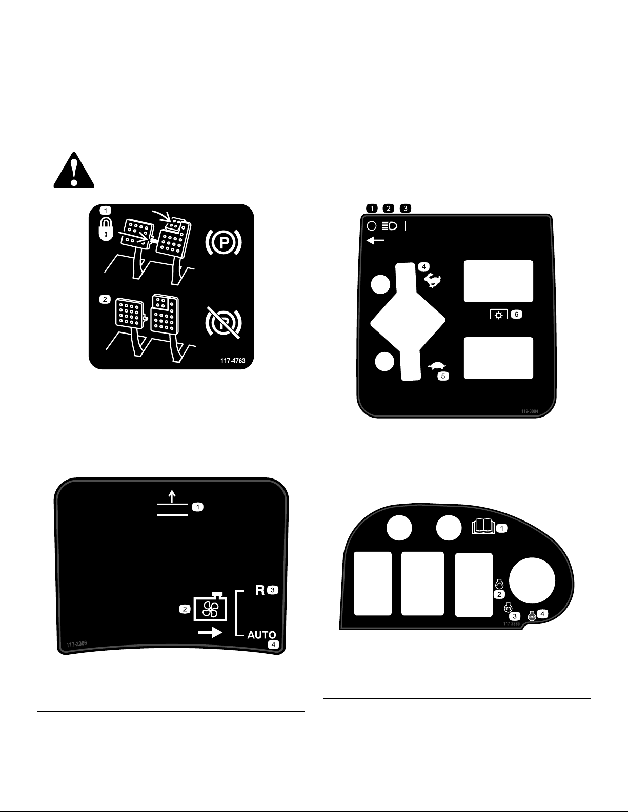
117-4763
1.Toengagetheparking
brake,securethebrake
pedalswiththelockingpin,
presstheparkingbrake
pedalsandengagethetoe
pedal.
117-2386
1.Raisedeck3.Reverse
2.Blowofffan
2.Todisengagetheparking
brake,disengagethe
lockingpinandreleasethe
pedals.
4.Automatic
119-3884
1.Off
2.Headlights
3.On6.PowerT ake-off(PTO)
1.ReadtheOperators
Manual.
2.Engine—start4.Engine—stop
4.Fast,throttle
5.Slow,throttle
117–2385
3.Engine—preheat
7
Page 8
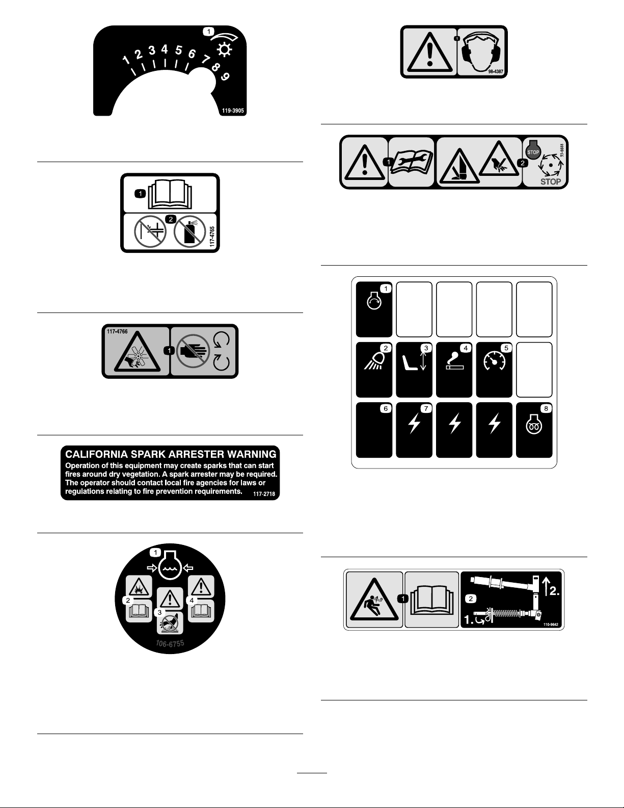
1.Reelspeed
120-1672
10A
20A
10A
10A
10A
2A
7.5A
7.5A
7.5A
TEC-5002
60A
98-4387
1.Warning—wearhearingprotection.
119-3905
93-6688
117-4765
1.ReadtheOperator'sManual.
2.Donotusestartingaids.
117-4766
1.Cutting/dismembermenthazard;fan—stayawayfrom
movingparts.
117–2718
1.Warning—readthe
instructionsbefore
servicingorperforming
maintenance.
2.Cuttinghazardofhandor
foot—stoptheengineand
waitformovingpartsto
stop.
120-1672
1.Starter,20A5.Gauges,10A
2.Worklight,10A
3.Seat,10A
4.Powerpoint,10A8.Enginepreheat,60A
6.GM4500controller,2A
7.Powersupplied,7.5A
1.Enginecoolantunder
pressure.
2.Explosionhazard—read
theOperator'sManual.
106-6755
3.Warning—donottouchthe
hotsurface.
4.Warning—readthe
Operator'sManual.
110-9642
1.Storedenergyhazard—readtheOperator'sManual.
2.Movethecotterpintotheholeclosesttotherodbracket
andthenremovetheliftarmandpivotyoke.
8
Page 9

120-1683
1.Warning—readtheOperator'sManual,donotoperatethis
machineunlessyouaretrained.
2.Warning—readtheOperator'sManualbeforetowingthe
machine.
3.Tippinghazard—slowmachinebeforeturning,donotturnat
highspeeds;lowerthecuttingunitwhendrivingdownslopes;
usearolloverprotectionsystemandweartheseatbelt
4.Warning—donotparkthemachineonslopes;engagethe
parkingbrake,lowerthecuttingunits,stoptheengineand
removetheignitionkeybeforeleavingthemachine.
5.Thrownobjecthazard—keepbystandersasafedistancefrom
themachine.
6.Entanglementhazard,belt—stayawayfrommovingparts,
keepallguardsandshieldsinplace.
120-1681
1.5Bladecuttingunit3.11Bladecuttingunit
2.8Bladecuttingunit4.Mowandbacklap6.Machinespeed
5.ReadtheOperator'sManual.
9
Page 10
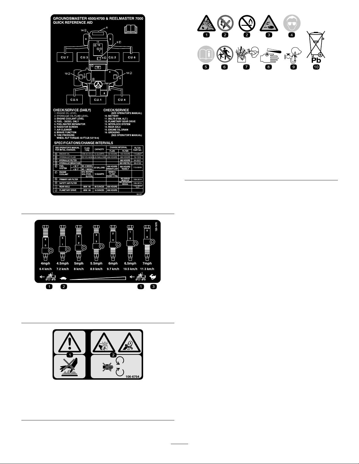
BatterySymbols
Someorallofthesesymbolsareonyourbattery
1.Explosionhazard
2.Nore,opename,or
smoking.
3.Causticliquid/chemical
burnhazard
4.Weareyeprotection9.Flusheyesimmediately
5.ReadtheOperator's
Manual.
6.Keepbystandersasafe
distancefromthebattery .
7.Weareyeprotection;
explosivegasescan
causeblindnessandother
injuries
8.Batteryacidcancause
blindnessorsevereburns.
withwaterandgetmedical
helpfast.
10.Containslead;donot
discard.
120-1671
120-1670
1.Tractionunitspeed3.Fast
2.Slow
106-6754
1.Warning—donottouchthehotsurface.
2.Cutting/dismembermenthazard,fanandentanglement
hazard,belt—stayawayfrommovingparts.
10
Page 11

Setup
LooseParts
Usethechartbelowtoverifythatallpartshavebeenshipped.
ProcedureDescription
1
2
3
4
5
6
MediaandAdditionalParts
Description
Operator'sManual
EngineOperator'sManual
PartsCatalog
Nopartsrequired
Fronthoseguide-R.H.1
Fronthoseguide-L.H.1
Nopartsrequired
Cuttingunitkickstand
Nopartsrequired
Nopartsrequired
Qty.
1
1
1
Readbeforeoperatingmachine
Readbeforeoperatingengine
Usetoreferencepartnumbers
Qty.
Use
–
–
1
–
–
Adjustthesupportrollers
Installthecuttingunits
Adjusttheturfcompensationspring.
InstalltheCuttingUnitKickstand.
Greasethemachine.
Checktherearaxlelubricant,hydraulic
uid,andengineoillevels
Use
OperatorTrainingMaterial
1
Viewbeforeoperatingmachine
Note:Determinetheleftandrightsidesofthemachinefromthenormaloperatingposition.
11
Page 12
1
g019541
1
2
3
AdjustingtheSupportRollers
NoPartsRequired
Procedure
Dependingonwhatwidthcuttingunitsaretobeinstalled
onthetraction,adjustthesupportrollersasfollows:
•Ifusing27inchcuttingunits,therollersaretobe
installedintheuppermountingholesofsupport
assemblychannels(
•Ifusing32inchcuttingunits,therollersaretobe
installedinthelowermountingholesofsupport
assemblychannels(Figure3).
Figure3).
2.Removetheshippingbracketsanddiscard.
3.Removethecuttingunitsfromthecartons.Assemble
andadjustasdescribedinthecuttingunitOperator's
Manual.
4.Makesurethecounterweight(
totheproperendofthecuttingunitasdescribedin
thecuttingunitOperator'sManual.
Figure4)isinstalled
Figure3
1.Supportassemblychannel3.Usethisholefor32inch
cuttingunits
2.Usethisholefor27inch
cuttingunits
2
InstallingtheCuttingUnits
Partsneededforthisprocedure:
Figure4
1.Counterweight
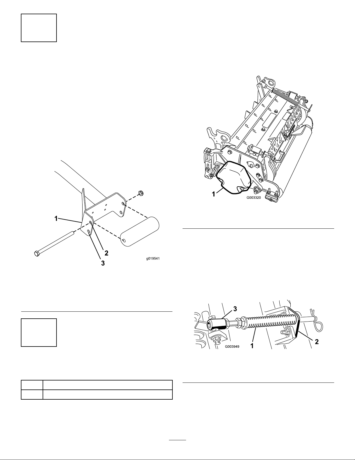
5.Allthecuttingunitsareshippedwiththeturf
compensationspringmountedtotherightsideofthe
cuttingunit.Theturfcompensationspringmustbe
mountedtothesamesideofthecuttingunitasthe
reeldrivemotor.Repositiontheturfcompensation
asfollows:
A.Removethe2carriageboltsandnutssecuring
therodbrackettothecuttingunittabs(
Figure5
1.Turfcompensationspring3.Springtube
2.Rodbracket
Figure5).
1Fronthoseguide-R.H.
1Fronthoseguide-L.H.
Procedure
1.Removethereelmotorsfromtheshippingbrackets.
B.Removetheangenutsecuringthespringtube
bolttothecarrierframetab(Figure5)Remove
theassembly .
C.Mountthespringtubebolttotheoppositetab
onthecarrierframeandsecurewiththeange
12
Page 13
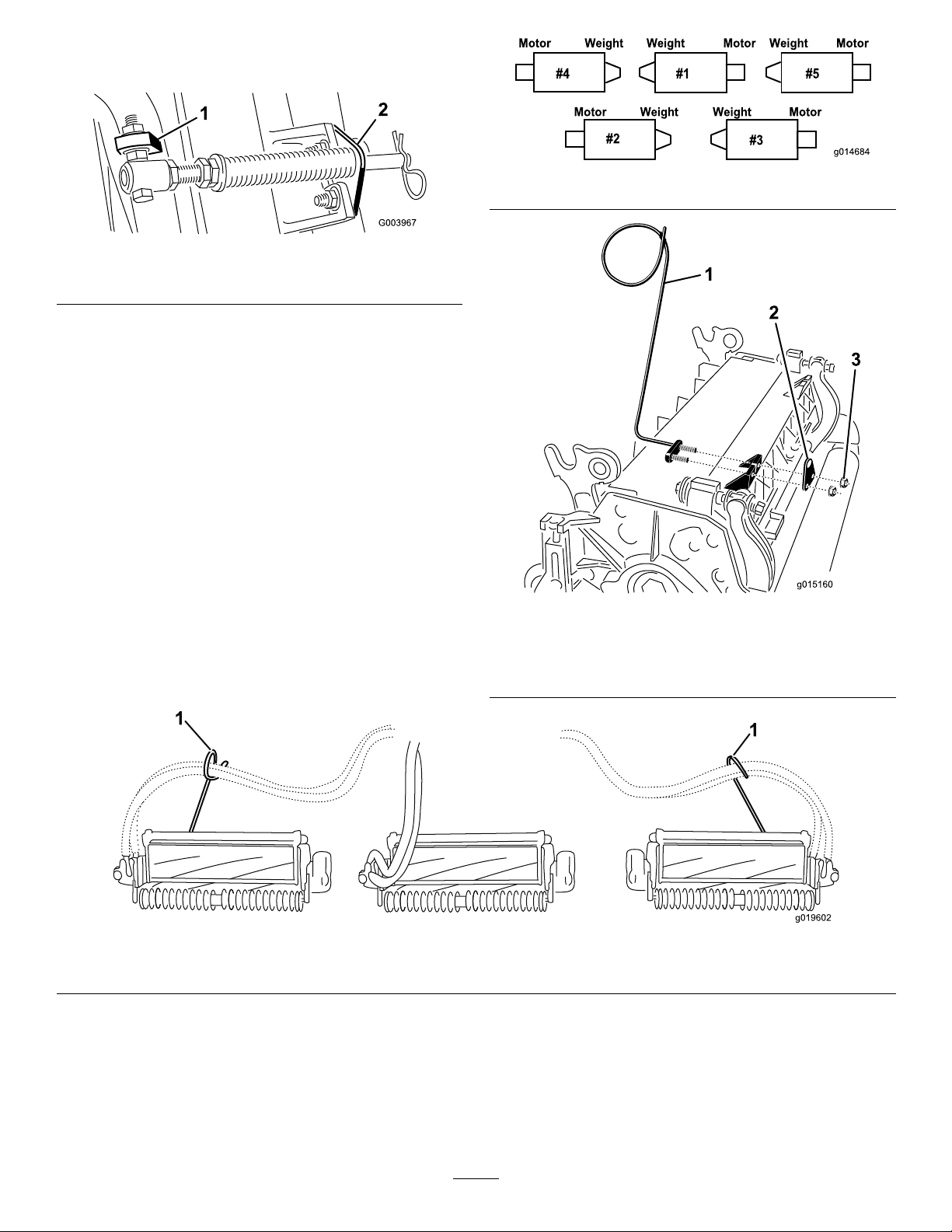
nut.Theboltheadistobepositionedtothe
g019602
1
1
outersideofthetabasshowninFigure6.
Figure6
Figure7
1.Oppositecarrierframetab
2.Rodbracket
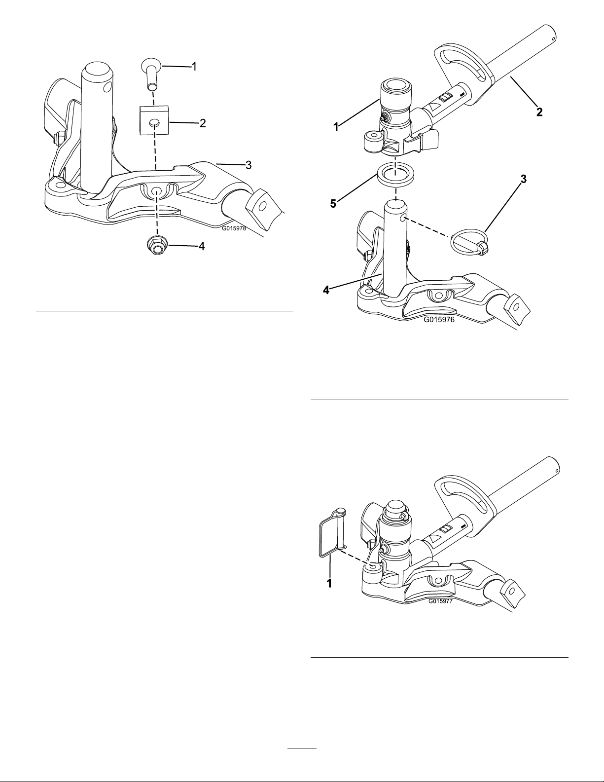
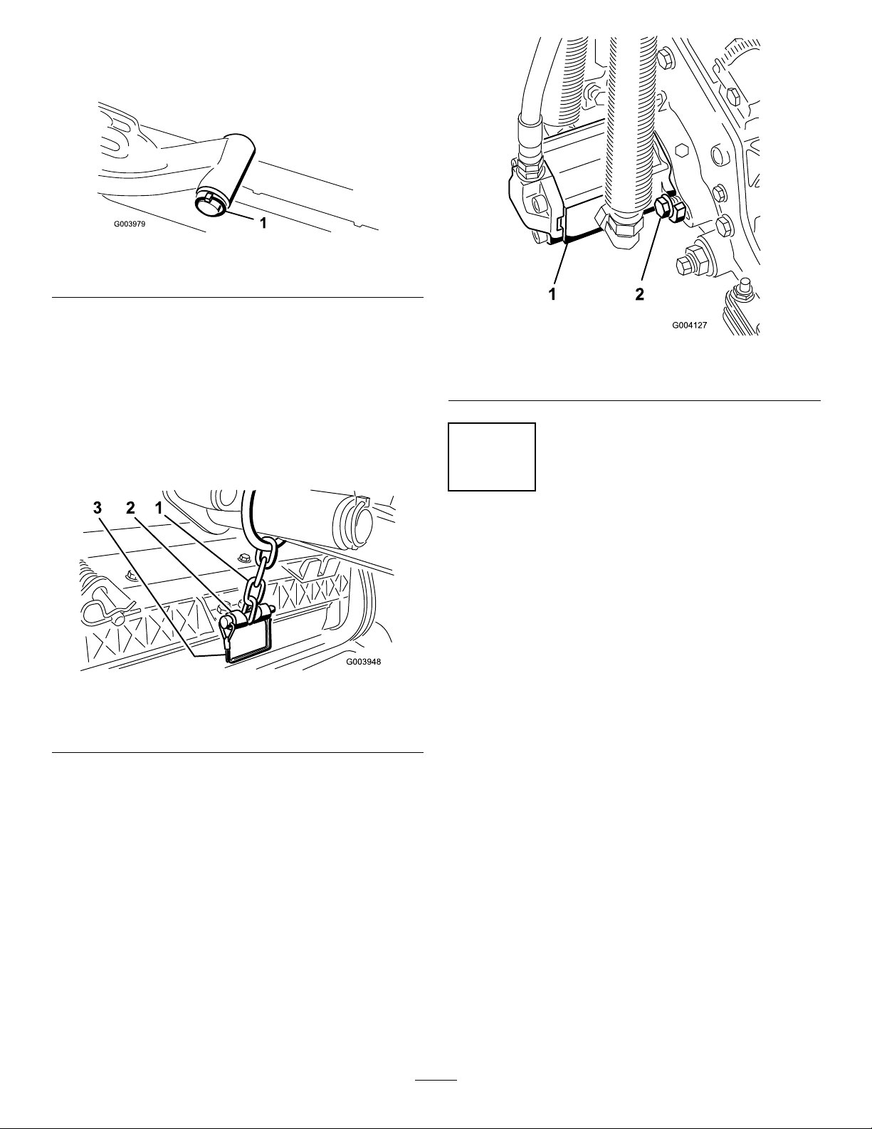
D.Mounttherodbrackettothecuttingunittabs
withthecarriageboltsandnuts(Figure6).Also,
onthecuttingunit,mountthelefthandhose
guidetothefrontofthecuttingunittabswhen
reinstallingtherodbracket(
Figure8).
Important:Onthe#4(leftfront)and#5
(rightfront)cuttingunits,usetherodbracket
mountingnutstoinstallthehoseguidesto
thefrontofthecuttingunittabs.Thehose
guidesshouldleantowardthecentercutting
unit(Figure7throughFigure9).
1.Hoseguide(Lefthand
shown)
2.Rodbracket
Figure8
3.Nuts
1.Hoseguides(eachmustleantowardthecentercuttingunit)
Note:Wheninstallingorremovingthecutting
units,makesurethehairpincotterisinstalled
inthespringrodholenexttotherodbracket.
Otherwise,thehairpincottermustbeinstalledin
theholeintheendoftherod.
Figure9
6.On27inchcuttingunitsonly ,increasethesteering
ontherearcuttingunitsbyremovingthe(2)pivot
spacers,hexsocketscrewsandangelocknuts
(Figure10)fromtherear(#2and#3)cuttingunit
carrierframes(Figure7).
13
Page 14
Note:32inchcuttingunitsarenotequippedwith
1
2
3
4
G015978
G015976
1
2
3
4
5
1
G015977
pivotspacers.
Figure10
1.Hexsocketscrew
2.Pivotspacer4.Flangelocknut
3.Carrierframe
7.Loweralltheliftarmscompletely.
8.Coatthecarrierframeshaftwithcleangrease
Figure11).
(
9.Forthefrontcuttingunits,slideacuttingunitunder
theliftarmwhileinsertingthecarrierframeshaftup
intotheliftarmpivotyoke(
Figure11).Makesure
thethrustwasherisinpositiononthecarrierframe
shaft.
10.Securethecarrierframeshafttotheliftarmyoke
withtheKlikpin(Figure11).
Figure11
1.Liftarmpivotyoke4.Carrierframeshaft
2.Liftarm
3.Klikpin
5.Thrustwasher
11.Tolock(x)thesteeringonthecuttingunits,secure
thepivotyoketothecarrierframewiththesnapper
pin(Figure12).
Figure12
1.Snapperpin
Note:Fixedsteeringisrecommendedwhen
cuttingsidehills.
12.Usethefollowingprocedureontherearcuttingunits
whentheheightofcutisabove3/4inch.
14
Page 15
A.Removethelynchpinandwashersecuringthe
liftarmpivotshafttotheliftarmandslidethe
liftarmpivotshaftoutoftheliftarm(Figure13).
Figure13
1.Liftarmpivotshaftlynchpinandwasher
B.Inserttheliftarmyokeontothecarrierframe
shaft(Figure11).
C.Inserttheliftarmshaftintotheliftarm
andsecureitwiththewasherandlynchpin
Figure13).
(
13.Securetheliftarmchaintothechainbracketwith
thesnapperpin(Figure14).Usethenumberofchain
linksdescribedinthecuttingunitOperator'sManual.
Figure15
1.Reeldrivemotor2.Mountingbolts
3
Figure14
1.Liftarmchain3.Snapperpin
2.Chainbracket
14.Coatthesplineshaftofthereelmotorwithclean
grease.
15.OilthereelmotorO-ringandinstallitontothe
motorange.
16.Installthemotorbyrotatingitclockwisesothatthe
motorangesclearthebolts(Figure15).Rotatethe
motorcounterclockwiseuntiltheangesencirclethe
boltsthentightenthebolts.
AdjustingtheTurf
CompensationSpring
NoPartsRequired
Procedure
Theturfcompensationspring(Figure16)transfers
weightfromthefronttotherearroller.(Thishelps
toreduceawavepatternintheturf,alsoknownas
marcellingorbobbing.)
Important:Makespringadjustmentswiththe
cuttingunitmountedtothetractionunit,pointing
straightaheadandloweredtotheshopoor.
1.Makesurethehairpincotterisinstalledintherear
holeinthespringrod(
Note:Whenservicingthecuttingunit,movethe
hairpincottertothespringrodholenexttotheturf
compensationspring.
Figure16).
Important:Makesurethereelmotorhoses
arenottwisted,kinkedorintheriskofbeing
pinched.
15
Page 16
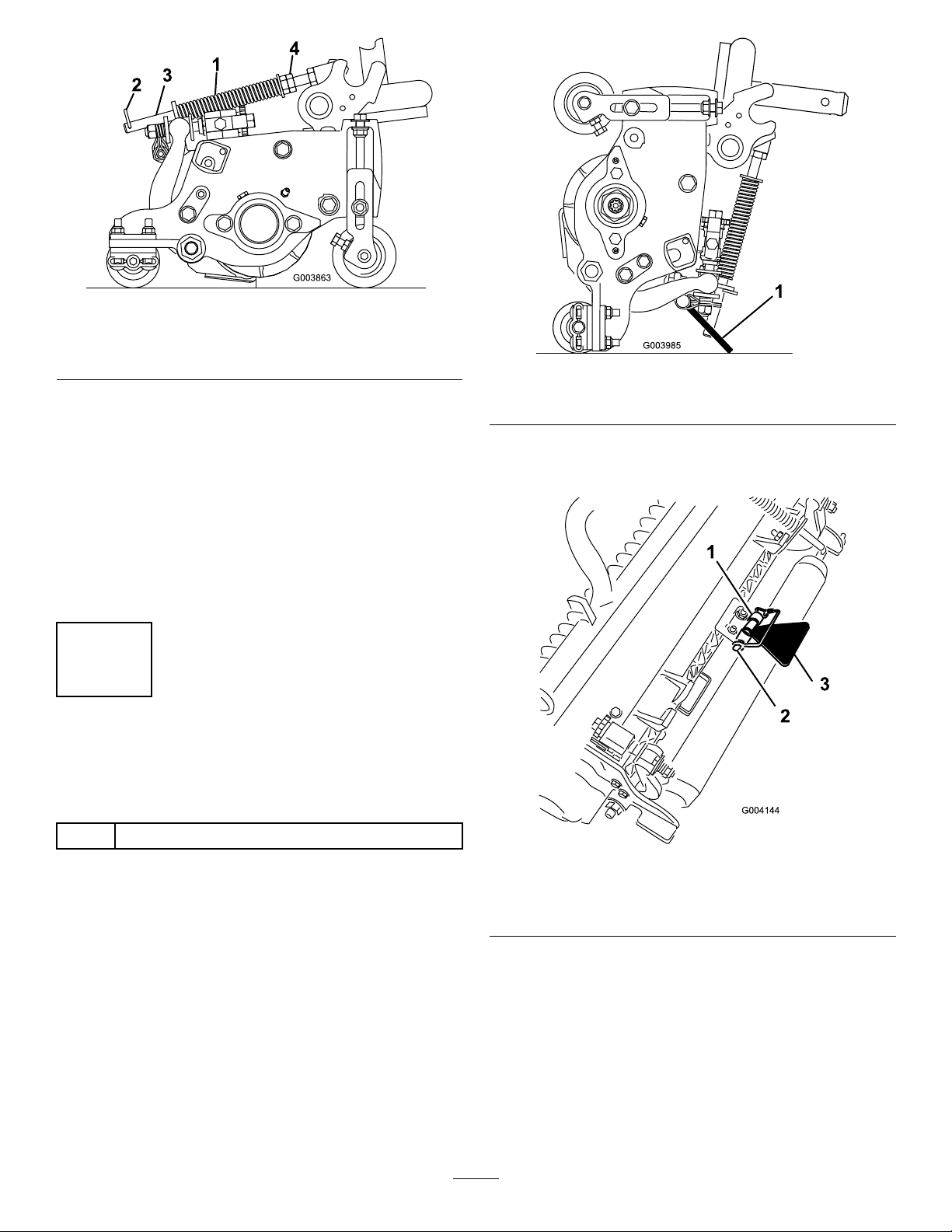
Figure16
1.Turfcompensationspring3.Springrod
2.Hairpincotter4.Hexnuts
Figure17
2.Tightenthehexnutsonthefrontendofthespring
roduntilthecompressedlengthofthespringis6.25
inches(15.9cm)(Figure16).
Note:Whenoperatingonroughterraindecrease
thespringlengthby1/2inch.Groundfollowingwill
beslightlydecreased.
Note:Theturfcompensationsettingwillneedto
beresetiftheHOCsettingortheAggressiveness
ofCutsettingischanged.
4
UsingtheCuttingUnit
Kickstand
Partsneededforthisprocedure:
1
Cuttingunitkickstand
1.Cuttingunitkickstand
Securethekickstandtothechainbracketwiththe
snapperpin(Figure18).
Figure18
Procedure
Wheneverthecuttingunithastobetippedtoexpose
thebedknife/reel,propuptherearofthecuttingunit
withthekickstandtomakesurethenutsontheback
endofthebedbaradjustingscrewsarenotrestingonthe
worksurface(Figure17).
1.Chainbracket3.Cuttingunitkickstand
2.Snapperpin
16
Page 17
ProductOverview
5
GreasingtheMachine
NoPartsRequired
Procedure
Beforethemachineisoperated,itmustbegreasedto
ensureproperlubrication.RefertoLubricationsection.
Failuretoproperlygreasethemachinewillresultin
prematurefailureofcriticalparts.
6
CheckingFluidLevels
NoPartsRequired
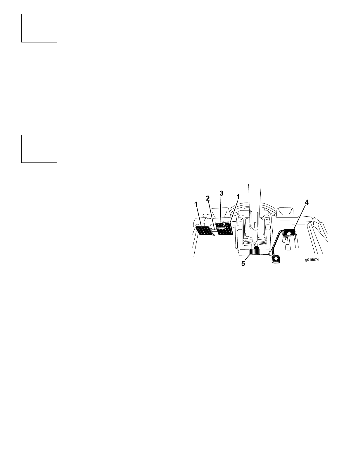
Controls
BrakePedals
Twofootpedals(Figure19)operateindividualwheel
brakesforturningassistanceandtoaidinobtaining
bettersidehilltraction.
PedalLockingLatch
Thepedallockinglatch(Figure19)connectsthepedals
togethertoengagetheparkingbrake.
ParkingBrakePedal
Toengagetheparkingbrake,(Figure19)connectthe
pedalstogetherwiththepedallockinglatch,pushdown
ontherightbrakepedalwhileengagingthetoepedal.To
releasetheparkingbrake,pressoneofthebrakepedals
untiltheparkingbrakelatchretracts.
Procedure
1.Checktherearaxlelubricantlevelbeforetheengine
isrststarted,refertoCheckingtheRearAxle
LubricantinDriveSystemMaintenance.
2.Checkthehydraulicuidlevelbeforetheengineis
rststarted,refertoCheckingtheHydraulicFluid
LevelinOperation.
3.Checktheengineoillevelbeforeandaftertheengine
isrststarted,refertoCheckingtheEngineOil
LevelinOperation.
Figure19
1.Brakepedal4.Tractionpedal
2.Pedallockinglatch5.Tiltsteeringpedal
3.Parkingbrakepedal
TractionPedal
Thetractionpedal(Figure19)controlsforwardand
reverseoperation.Depressthetopofthepedaltomove
forwardandthebottomtomovebackward.Ground
speeddependsonhowfarthepedalisdepressed.For
noload,maximumgroundspeed,fullydepressthepedal
whilethethrottleisinFast.
Tostop,reduceyourfootpressureonthetractionpedal
andallowittoreturntothecenterposition.
TiltSteeringPedal
Totiltthesteeringwheeltowardsyou,pressthefoot
pedal(Figure19)down,andpullthesteeringtower
17
Page 18

towardyoutothemostcomfortablepositionandthen
releasethepedal.
MowSpeedLimiter
ChargeIndicator
Thechargeindicator(Figure21)illuminateswhenthe
systemchargingcircuitmalfunctions.
Whenthemowspeedlimiter(Figure20)isippedupit
willcontrolthemowspeedandallowthecuttingunits
tobeengaged.Eachspaceradjuststhemowingspeed
by½mileperhour.Themorespacersyouhave,onthe
topoftheboltthesloweryouwillgo.Fortransport,ip
backthemowspeedlimiterandyouwillhavemaximum
transportspeed.
SpeedLimiterScrews
Adjustthescrew(s)(Figure20)tolimittheamountthe
tractionpedalcanbedepressedintheforwardorreverse
directiontolimitspeed.
Important:Thespeedlimiterscrewmuststopthe
tractionpedalbeforethepumpreachesfullstroke
ordamagetothepumpmayoccur.
KeySwitch
Thekeyswitch(Figure21)hasthreepositions:Off,
On/Preheat,andStart.
PTOSwitch
ThePTOswitch(Figure21)hastwopositions:Out
(start)andIn(stop).PullthePTObuttonouttoengage
thecuttingunitblades.Pushinthebuttontodisengage
thecuttingunitblades.
Figure20
1.Reversespeedlimiter
screw
2.Forwardspeedlimiter
screw
3.Spacers
4.Mowspeedlimiter
DiagnosticLight
Thediagnosticlight(Figure21)willilluminateshoulda
systemfaultberecognized.
EngineCoolantTemperatureGauge
Duringnormaloperatingconditionsthegauge
(Figure21)shouldbeinthegreenrange.Checkthe
coolingsystemifthegaugegoestotheyelloworred
range.
EngineOilPressureWarningLight
Thelight(Figure21)illuminateswhentheengineoil
pressureisdangerouslylow .
Figure21
1.Diagnosticlight
2.Enginecoolant
temperaturegauge
3.Engineoilpressure
warninglight
4.Chargeindicator10.Glowplugindicatorlight
5.Keyswitch11.Enginecoolant
6.PTOswitch
7.Liftswitch
8.Throttlecontrol
9.Lightswitch
temperaturewarning
light
LiftSwitch
Theliftswitch(Figure21)raisesandlowersthecutting
units.Presstheswitchforwardtolowerthecuttingunits
andbackwardtoraisethecuttingunits.Whenstarting
18
Page 19

themachine,withthecuttingunitsinthedownposition,
presstheliftswitchdowntoallowthecuttingunitsto
oatandmow .
hastwopositionsR(manualreverse)andAuto(normal).
RefertoEngineCoolingFanOperationintheOperation
Sectionofmanual.
ThrottleControl
Movethecontrol(Figure21)forwardtoincreasethe
enginespeedandrearwardtodecreasethespeed.
LightSwitch
Presstheloweredgeoftheswitch(Figure21)toturnon
thelights.Presstheupperedgeoftheswitchtoturn
offthelights.
GlowPlugIndicatorLight
Whenlit,theglowplugindicatorlight(Figure21)
indicatesthattheglowplugsareon.
EngineCoolantTemperatureWarning
Light
Thelight(Figure21)illuminatesandthecuttingunits
shutdown(PTOdisengages).Ifthetemperature
continuestorisetheenginewillshutdown.
PowerPoint
BagHolder
Usethebagholder(Figure22)forstorage.
HourMeter
Thehourmeter(Figure22)showsthetotalhoursthat
themachinehasbeenoperated.
BacklapLevers
Usethebacklapleversforbacklappingthereels
Figure23).
(
Thepowerpoint(Figure22)isusedtopoweroptional
12voltelectricalaccessories.
Figure22
1.Powerpoint3.Bagholder
2.Enginecoolingfanswitch
4.Hourmeter
Figure23
1.Frontbacklaplever2.Rearbacklaplever
ReelSpeedControl
Thereelspeedcontrolregulatesthespeedofthefront
andrearcuttingunits(Figure24).Thereelspeed
increasesastheknobisturnedclockwise.
EngineCoolingFanSwitch
Themachineisequippedwithahydraulicallydrivenauto
reversingenginecoolingfan.Thefanswitch(Figure22)
19
Page 20

1.Reelspeedcontrols
Weightgauge
Indicateswhentheseatisadjustedtotheweightofthe
operator(Figure26).Heightadjustmentismadeby
positioningthesuspensionwithintherangeofthegreen
region.
Figure24
FuelGauge
Thefuelgauge(Figure25)indicatestheleveloffuelin
thetank.
Figure25
1.Fuelgauge
SeatAdjustments
ForeandAftAdjustingLever
Pulloutonthelevertoslidetheseatforeoraft
(Figure26).
Figure26
1.Weightgauge
2.Weightadjustinglever5.Armrestadjustingknob
3.ForeandAftadjusting
lever
4.Seatbackadjustinglever
WeightAdjustingLever
Adjustforoperatorweight(Figure26).Pulluponthe
levertoincreasetheairpressureandpushdownto
decreasetheairpressure.Theproperadjustmentis
attainedwhentheweightgaugeisinthegreenregion.
SeatArmRestAdjustingKnob
Rotatetheknobtoadjusttheseatarmrestangle
(Figure26).
SeatBackAdjustingLever
Movethelevertoadjusttheseatbackangle(Figure26).
20
Page 21

Specications
Note:Specicationsanddesignaresubjecttochange
withoutnotice.
TractionUnitSpecications
Widthofcut121inches(307cm)
Overallwidth,cuttingunits
down
Overallwidth,cuttingunitsup
(transport)
Overalllength145.8inches(370cm)
HeightwithROPS87inches(220cm)
TrackWidth,front90inches(229cm)
TrackWidth,rear
Wheelbase
NetWeight(withnocutting
unitsandnouids)
Attachments/Accessories
136inches(345cm)
94inches(239cm)
55.5inches(141cm)
67-1/2inches(171cm)
3470lb(1574kg)
AselectionofToroapprovedattachmentsand
accessoriesisavailableforusewiththemachineto
enhanceandexpanditscapabilities.Contactyour
AuthorizedServiceDealerorDistributororgoto
www.Toro.comforalistofallapprovedattachments
andaccessories.
21
Page 22

Operation
Note:Determinetheleftandrightsidesofthe
machinefromthenormaloperatingposition.
CAUTION
Thismachineproducessoundlevelsinexcessof
85dBAattheoperator'searandcancausehearing
lossthroughextendedperiodsofexposure.
Wearhearingprotectionwhenoperatingthis
machine.
CAUTION
Ifyouleavethekeyintheignitionswitch,someone
couldaccidentlystarttheengineandseriously
injureyouorotherbystanders.
1.Parkthemachineonalevelsurface.
2.Unlockthehoodlatchesandopenthehood
Figure27).
(
Removethekeyfromtheignitionbeforeyoudo
anymaintenance.
CheckingtheEngineOilLevel
ServiceInterval:Beforeeachuseordaily
Theengineisshippedwithoilinthecrankcase;
however,theoillevelmustbecheckedbeforeandafter
theengineisrststarted.
Thecrankcasecapacityisapproximately10qt.(9.5l)
withthelter.
Usehigh-qualityengineoilthatmeetsthefollowing
specications:
•APIClassicationLevelRequired:CH-4,CI-4or
higher.
•Preferredoil:SAE15W -40(above0°F)
•Alternateoil:SAE10W -30or5W -30(all
temperatures)
Note:ToroPremiumEngineoilisavailable
fromyourdistributorineither15W-40or10W-30
viscosity.Seethepartscatalogforpartnumbers.
Figure27
1.Hoodlatch
3.Removethedipstick,wipeitclean,installthe
dipstickintothetube,andpullitoutagain.
Theoillevelshouldbeinthesaferange(
Figure28
1.Dipstick
Figure28).
Note:Thebesttimetochecktheengineoilis
whentheengineiscoolbeforeithasbeenstarted
fortheday .Ifithasalreadybeenrun,allowthe
oiltodrainbackdowntothesumpforatleast10
minutesbeforechecking.Iftheoillevelisator
belowthe‘add’markonthedipstick,addoilto
bringtheoilleveltothe‘full’mark.Donotoverll.
Iftheoillevelisbetweenthe‘full’and‘add’marks,
nooiladditionisrequired.
4.Iftheoilisbelowthesaferange,removethellcap
(Figure29)andaddoiluntilthelevelreachesthe
FULLmark.Donotoverll.
22
Page 23

Figure29
1.Oilllcap
Note:Whenusingdifferentoil,drainalloldoil
fromthecrankcasebeforeaddingnewoil.
Figure30
5.Installtheoilllcapanddipstick.
6.Closethehoodandsecureitwiththelatches.
CheckingtheCoolingSystem
ServiceInterval:Beforeeachuseordaily
Checklevelofcoolantatthebeginningofeachday.
Capacityofsystemis13qt.(12.3l).
1.Carefullyremovetheradiatorcap.
CAUTION
Iftheenginehasbeenrunning,thepressurized,
hotcoolantcanescapeandcauseburns.
•Donotopentheradiatorcapwhenthe
engineisrunning.
•Usearagwhenopeningtheradiatorcap,
andopenthecapslowlytoallowsteamto
escape.
1.Expansiontank
2.Checkthecoolantlevelintheradiator.Theradiator
shouldbelledtothetopofthellerneckandthe
expansiontanklledtotheFULLmark(Figure30).
3.Ifthecoolantislow ,adda50/50mixtureofwater
andethyleneglycolantifreeze.Donotusewater
onlyoralcohol/methanolbasecoolants.
4.Installtheradiatorcapandexpansiontankcap.
FillingtheFuelTank
Useonlyclean,freshdieselfuelorbiodieselfuelswith
low(<500ppm)orultralow(<15ppm)sulfurcontent.
Theminimumcetaneratingshouldbe40.Purchase
fuelinquantitiesthatcanbeusedwithin180daysto
ensurefuelfreshness.
Fueltankcapacity:22gallons(83l).
Usesummergradedieselfuel(No.2-D)attemperatures
above20°F(-7°C)andwintergrade(No.1-Dor
No.1-D/2-Dblend)belowthattemperature.Useof
wintergradefuelatlowertemperaturesprovideslower
ashpointandcoldowcharacteristicswhichwillease
startingandreducefuellterplugging.
Useofsummergradefuelabove20°F(-7°C)will
contributetowardlongerfuelpumplifeandincreased
powercomparedtowintergradefuel.
Important:Donotusekeroseneorgasoline
insteadofdieselfuel.Failuretoobservethis
cautionwilldamagetheengine.
23
Page 24

WARNING
DANGER
Fuelisharmfulorfatalifswallowed.Long-term
exposuretovaporscancauseseriousinjuryand
illness.
•Avoidprolongedbreathingofvapors.
•Keepfaceawayfromnozzleandgastankor
conditioneropening .
•Keepfuelawayfromeyesandskin.
BiodieselReady
Thismachinecanalsouseabiodieselblendedfuel
ofuptoB20(20%biodiesel,80%petrodiesel).The
petrodieselportionshouldbeloworultralowsulfur.
Observethefollowingprecautions:
•Thebiodieselportionofthefuelmustmeet
specicationASTMD6751orEN14214.
•TheblendedfuelcompositionshouldmeetASTM
D975orEN590.
•Paintedsurfacesmaybedamagedbybiodiesel
blends.
•UseB5(biodieselcontentof5%)orlesserblends
incoldweather.
Incertainconditions,fuelisextremelyammable
andhighlyexplosive.Areorexplosionfromfuel
canburnyouandothersandcandamageproperty.
•Useafunnelandllthefueltankoutdoors,in
anopenarea,whentheengineiscold.Wipe
upanyfuelthatspills.
•Neverllthefueltankinsideanenclosedtrailer.
•Donotllthefueltankcompletelyfull.Add
fueltothefueltankuntilthelevelis1in.(25
mm)belowthetopofthetank,nottheller
neck.Thisemptyspaceinthetankallowsthe
fueltoexpand.
•Neversmokewhenhandlingfuel,andstay
awayfromanopenameorwherefuelfumes
maybeignitedbyaspark.
•Storefuelinanapprovedcontainerandkeepit
outofthereachofchildren.Neverbuymore
thana180-daysupplyoffuel.
•Donotoperatewithoutentireexhaustsystem
inplaceandinproperworkingcondition.
1.Removethefueltankcap(Figure31).
•Monitorseals,hoses,gasketsincontactwithfuelas
theymaybedegradedovertime.
•Fuellterpluggingmaybeexpectedforatimeafter
convertingtobiodieselblends.
•Contactyourdistributorifyouwishformore
informationonbiodiesel.
Figure31
1.Fueltankcap
2.Fillthetanktoabout1inch(25mm)belowthetop
ofthetank,notthellerneck,withNo.2diesel
fuel.Theninstallthecap.
Note:Ifpossible,llthefueltankaftereachuse.
Thiswillminimizepossiblebuildupofcondensation
insidethefueltank.
24
Page 25

DANGER
Incertainconditionsduringfueling,static
electricitycanbereleasedcausingasparkwhich
canignitethefuelvapors.Areorexplosionfrom
fuelcanburnyouandothersandcandamage
property.
•Alwaysplacefuelcontainersontheground
awayfromyourvehiclebeforelling.
•Donotllfuelcontainersinsideavehicleoron
atruckortrailerbedbecauseinteriorcarpets
orplastictruckbedlinersmayinsulatethe
containerandslowthelossofanystaticcharge.
•Whenpractical,removeequipmentfromthe
truckortrailerandrefueltheequipmentwith
itswheelsontheground.
•Ifthisisnotpossible,thenrefuelsuch
equipmentonatruckortrailerfromaportable
container,ratherthanfromafueldispenser
nozzle.
•Ifafueldispensernozzlemustbeused,keep
thenozzleincontactwiththerimofthefuel
tankorcontaineropeningatalltimesuntil
fuelingiscomplete.
ViscosityIndexASTM
D2270
PourPoint,ASTMD97-34°Fto-49°F
IndustrySpecications:
VickersI-286-S(QualityLevel),VickersM-2950-S
(QualityLevel),DenisonHF-0
140to160
PremiumBiodegradableHydraulicFluid-Mobil
EALEnviroSyn46H
Important:MobilEALEnviroSyn46Histheonly
syntheticbiodegradableuidapprovedbyT oro.
Thisuidiscompatiblewiththeelastomersused
inT orohydraulicsystemsandissuitablefora
wide-rangeoftemperatureconditions.Thisuidis
compatiblewithconventionalmineraloils,butfor
maximumbiodegradabilityandperformancethe
hydraulicsystemshouldbethoroughlyushedof
conventionaluid.Theoilisavailablein5gallon
(19l)containersor55gallondrumsfromyour
MobilDistributor.
Note:Manyhydraulicuidsarealmostcolorless,
makingitdifculttospotleaks.Areddyeadditivefor
thehydraulicsystemoilisavailablein2/3oz.(20ml)
bottles.Onebottleissufcientfor4-6gal(15-221)
ofhydraulicoil.Orderpartno.44-2500fromyour
authorizedTorodistributor.
CheckingtheHydraulicFluid
Level
ServiceInterval:Beforeeachuseordaily
Themachinesreservoirislledatthefactorywith
approximately7.5U .S.gallons(28.4l)ofhighquality
hydraulicuid.Checkthelevelofthehydraulicuid
beforetheengineisrststartedanddailythereafter.
Therecommendedreplacementuidisasfollows:
ToroPremiumAllSeasonHydraulicFluid
(Availablein5gallonpailsor55gallondrums.Seeparts
catalogorTorodistributorforpartnumbers.)
Alternateuids:IftheTorouidisnotavailable,other
uidsmaybeusedprovidedtheymeetallthefollowing
materialpropertiesandindustryspecications.Wedo
notrecommendtheuseofsyntheticuid.Consult
withyourlubricantdistributortoidentifyasatisfactory
productNote:Torowillnotassumeresponsibilityfor
damagecausedbyimpropersubstitutions,souseonly
productsfromreputablemanufacturerswhowillstand
behindtheirrecommendation.
1.Positionthemachineonalevelsurface,lowerthe
cuttingunits,stoptheengine,andremovethekey.
2.Cleantheareaaroundthellerneckandcapofthe
hydraulictank(
Figure32).Removethecapfrom
thellerneck.
HighViscosityIndex/LowPourPointAnti-wear
HydraulicFluid,ISOVG46
MaterialProperties:
Viscosity,ASTMD445cSt@40°C44to48
cSt@100°C7.9to8.5
Figure32
1.Hydraulictankcap
25
Page 26

3.Removethedipstickfromthellerneckandwipe
itwithacleanrag.Insertthedipstickintotheller
neck;thenremoveitandchecktheuidlevel.The
uidlevelshouldbebetweenthetwomarksonthe
dipstick.
4.Ifthelevelislow ,addtheappropriateuidtoraise
theleveltotheuppermark.
5.Installthedipstickandcapontothellerneck.
Whenthetemperatureislessthan20°F(-7°C),the
startermotorcanberunfor30secondsonthen60
secondsofffor2attempts.
CAUTION
Shuttheengineoffandwaitforallmoving
partstostopbeforecheckingforoilleaks,loose
parts,andothermalfunctions.
CheckingtheTirePressure
ServiceInterval:Beforeeachuseordaily
Thetiresareover-inatedforshipping.Therefore,
releasesomeoftheairtoreducethepressure.The
correctairpressureinthetiresis12–15psi(83-103
kPa).Checkthetirepressuredaily.
Important:Maintaintherecommendedpressure
inalltirestoensureagoodquality-of-cut
andpropermachineperformance.Donot
under-inate.
StartingandStoppingthe
Engine
StartingtheEngine
Important:Thefuelsystemmustbebledifanyof
thefollowingsituationshaveoccurred:
•Theenginehasceasedrunningduetolackoffuel.
•Maintenancehasbeenperformeduponthefuel
systemcomponents.
StoppingtheEngine
Important:Allowenginetoidlefor5minutes
beforeshuttingitoffafterafullloadoperation.
Thisallowstheturbochargertocooldownbefore
shuttingtheengineoff.Failuretodosomaylead
toturbo-chargertrouble.
Note:Lowercuttingunitstothegroundwhenever
machineisparked.Thisrelievesthehydraulicloadfrom
thesystem,preventswearonsystempartsandalso
preventsaccidentalloweringofthecuttingunits.
1.MovethethrottlecontrolbackwardtotheSlow
position.
2.MovethePTOswitchtotheOffposition.
3.Settheparkingbrake.
4.RotatetheignitionkeytoOff.
5.Removethekeyfromtheswitchtoprevent
accidentalstarting.
CheckingtheInterlock
Switches
1.Removeyourfootfromthetractionpedaland
ensurethatitisinneutral.Ensurethattheparking
brakeisset.
2.Movethethrottlecontroltothelowidleposition.
3.TurntheignitionkeytotheRunposition.Theglow
indicatorwilllight.
4.Whentheglowindicatordims,turntheignitionkey
totheStartposition.Releasethekeyimmediately
whentheenginestartsandallowittoreturnto
theRunposition.Movethethrottlecontroltothe
desiredposition.
Important:Donotrunthestartermotor
morethan15secondsatatimeorpremature
starterfailuremayresult.Iftheenginefailsto
startafter15seconds,turnthekeytotheOff
position,recheckthecontrolsandprocedures,
wait15additionalseconds,andrepeatthe
startingprocedure.
ServiceInterval:Beforeeachuseordaily
CAUTION
Ifsafetyinterlockswitchesaredisconnectedor
damagedthemachinecouldoperateunexpectedly
causingpersonalinjury.
•Donottamperwiththeinterlockswitches.
•Checktheoperationoftheinterlockswitches
dailyandreplaceanydamagedswitchesbefore
operatingthemachine.
Themachinehasinterlockswitchesintheelectrical
system.Theseswitchesaredesignedtostoptheengine
whenoperatorgetsoffoftheseatwhenthetraction
pedalisdepressed.However,theoperatormaygetoff
oftheseatwhiletheengineisrunningandthetraction
pedalisinneutral.Althoughtheenginewillcontinue
torunifthePTOswitchisdisengagedandthetraction
26
Page 27

pedalisreleased,itisstronglyrecommendedthatthe
enginebestoppedbeforerisingfromtheseat.
Tochecktheoperationoftheinterlockswitches,
performthefollowingprocedure:
neutralposition.Theengineshouldkill.Ifthe
enginedoesnotkill,thereisamalfunctioninthe
interlocksystemthatshouldbecorrectedbefore
beginningoperation.
1.Drivethemachineslowlytoalarge,relativelyopen
area.Lowerthecuttingunit,stoptheengine,and
applytheparkingbrake.
2.Sitontheseatanddepressthetractionpedal.Try
tostarttheengine.Theengineshouldnotcrank.
Iftheenginecranks,thereisamalfunctioninthe
interlocksystemthatshouldbecorrectedbefore
beginningoperation.
3.Sitontheseatandstarttheengine.Risefromthe
seatandmovethePTOswitchtoOn.ThePTO
shouldnotengage.IfthePTOengages,thereisa
malfunctionintheinterlocksystemthatshouldbe
correctedbeforebeginningoperation.
4.Sitontheseat,engagetheparkingbrakeandstart
theengine.Movethetractionpedaloutofthe
SettingtheReelSpeed
Toachieveaconsistent,highquality-of-cutanda
uniformaftercutappearance,itisimportantthatyou
setthereelspeedcontrols(locatedundertheseat)
correctly.Adjustthereelspeedcontrolsasfollows:
1.Selecttheheight-of-cutatwhichthecuttingunits
areset.
2.Choosethedesiredgroundspeedbestsuitedfor
conditions.
3.Usingtheappropriategraphonthedecal(
determinetheproperreelspeedsetting.
Figure33)
Figure33
1.5bladecuttingunit3.1 1bladecuttingunit
2.8bladecuttingunit4.Mowandbacklap6.Machinespeed
5.ReadtheOperator'sManual.
Tosetthereelspeed,rotateknobs(Figure34)until
theindicatorarrowsareinlinewiththenumber
designatingthedesiredsetting.
Note:Thereelspeedcanbeincreasedordecreased
tocompensateforturfconditions.
27
Page 28

Figure35
1.Spring2.Springactuator
Figure34
1.Reelspeedcontrolknob
AdjustingtheLiftArm
Counterbalance
Youcanadjustthecounterbalanceontherear
cuttingunitliftarmstocompensatefordifferentturf
conditionsandtomaintainauniformheight-of-cutin
theroughconditionsorinareasofthatchbuildup.
Youcanadjusteachcounterbalancespringtooneof
foursettings.Eachincrementincreasesordecreases
counterbalanceonthecuttingunitby5lb(2.3kg).The
springscanbepositionedonthebacksideofthespring
actuatortoremoveallcounterbalance(forthposition).
1.Positionthemachineonalevelsurface,lowerthe
cuttingunits,stoptheengine,engagetheparking
brakes,andremovethekeyfromignitionswitch.
4.Movethespringactuatortothedesiredhole
locationandsecurewithlocknut.
5.Repeattheprocedureontheremainingspring.
AdjustingtheLiftArmTurn
AroundPosition
1.Positionthemachineonalevelsurface,lowerthe
cuttingunits,stoptheengine,engagetheparking
brakes,andremovethekeyfromignitionswitch.
2.Theliftarmswitchislocatedbehindthefrontright
liftarm(Figure36).
2.Insertatubeorsimilarobjectontothelong
springendtorelievethespringtensionduringthe
adjustment(
Figure35).
CAUTION
Thespringsareundertension.
Usecautionwhenadjustingthem.
3.Whilerelievingthespringtension,removethebolt
andlocknutsecuringthespringactuatortothe
bracket(Figure35).
Figure36
1.Switch
3.Loosentheswitchmountingscrews(Figure36)
andmovetheswitchuptoincreasetheliftarm
28
Page 29

turnaroundheightormovetheswitchdownto
decreasetheliftarmturnaroundheight.Tighten
themountingscrews.
JackingPoints
•Onthefrontofthemachineontheframeonthe
insideofeachdrivetire
PushingorTowingthe
Machine
Inanemergency,themachinecanbemovedforwardby
actuatingthebypassvalveinthevariabledisplacement
hydraulicpumpandpushingortowingthemachine.
Donotpushortowthemachineformorethan1/4
mile(0.4km).
Important:Donotpushortowthemachine
fasterthan2-3MPH(3-4.8km/h)becauseinternal
transmissiondamagemayoccur.Thebypassvalve
mustbeopenwheneverthemachineispushedor
towed.
Important:Ifthemachinemusttobepushedor
towedinreverse,thecheckvalveinthefour-wheel
drivemanifoldmustalsobebypassed.T obypass
thecheckvalve,connectahoseassembly(Hose
PartNo.95-8843,CouplerFittingNo.95-0985
[Qty.2],andHydraulicFittingNo.340-77[Qty.2])
tothereversetractionpressuretestportandthe
reversefour-wheeldrivepressureport.
1.Openhoodandremovethecentershroud
•Ontherearofthemachineatthecenteroftheaxle
TieDowns
•Oneachsideoftheframeunderthefrontsteps
•Therearbumper
UnderstandingtheDiagnostic
Light
Themachineisequippedwithadiagnosticlightwhich
indicatesiftheelectroniccontrollersensesanelectronic
malfunction.Thediagnosticlightislocatedonthe
controlarm(
isfunctioningcorrectlyandthekeyswitchismovedto
theOnposition,thecontrollerdiagnosticlightwillturn
ONfor3secondsandturnOFFtoindicatethelight
isworkingproperly .Ifthemachinekillsthelightwill
turnonsteadyuntilthekeypositionischanged.The
lightwillblinkifthecontrollerdetectsamalfunctionin
theelectricalsystem.Thelightwillstopblinkingand
automaticallyresetwhenthekeyswitchisturnedtothe
Offpositiononcethefaulthasbeenresolved.
Figure38).Whentheelectroniccontroller
2.Rotatethebypassvalve90°(1/4turn)ineither
directiontoopenandallowoiltobypassinternally
Figure37).Becauseuidisbypassed,themachine
(
canbeslowlymovedwithoutdamagingthe
transmission.Notethepositionofthevalvewhen
openingorclosing.
Figure37
1.Bypassvalve
Figure38
1.Diagnosticlight
Whenthecontrollerdiagnosticlightblinks,oneofthe
followingproblemshasbeendetectedbythecontroller:
•Oneoftheoutputshasbeenshorted.
•Oneoftheoutputsisopencircuited.
3.Rotatethebypassvalve90°(1/4turn)backbefore
startingtheengine.Donotexceed5-8ft.-lb.
(7-11N·m)torquetoclosethevalve.
Usingthediagnosticdisplay,determinewhichoutput
ismalfunctioning;refertoCheckingtheInterlock
Switches.
29
Page 30

Ifthediagnosticlightisnotilluminatedwhenthekey
switchisintheOnposition,thisindicatesthatthe
electroniccontrollerisnotoperating.Possiblecauses
areasfollows:
•Loop-backisnotconnected.
•Thelightisburnedout.
•Fusesareblown.
•Itisnotfunctioningcorrectly.
Checktheelectricalconnections,inputfuses,and
diagnosticlightbulbtodeterminethemalfunction.
Ensurethattheloop-backconnectorissecuredtothe
wireharnessconnector.
DiagnosticAceDisplay
Themachineisequippedwithanelectroniccontroller
whichcontrolsmostmachinefunctions.Thecontroller
determineswhatfunctionisrequiredforvariousinput
switches(i.e.seatswitch,keyswitch,etc.)andturns
ontheoutputstoactuatesolenoidsorrelaysforthe
requestedmachinefunction.
VerifyingtheInterlockSwitchFunction
1.Parkthemachineonalevelsurface,lowerthe
cuttingunits,stoptheengine,andengagethe
parkingbrake.
2.Removetheaccesspanellocatedbeneaththefront
oftheseat(
3.Locatethewireharnessandconnectorsnearthe
controller(Figure39).
1.Wireharnessandconnectors
Figure39).
Figure39
Fortheelectroniccontrollertocontrolthemachineas
desired,eachoftheinputswitches,outputsolenoids,
andrelaysmustbeconnectedandfunctioningproperly .
UsetheDiagnosticACEdisplaytohelpverifyand
correctelectricalfunctionsofthemachine.
CheckingtheInterlock
Switches
Thepurposeoftheinterlockswitchesistopreventthe
enginefromcrankingorstartingunlessthetraction
pedalisintheNeutralposition,thePTOswitchisin
theOFFposition,andtheliftswitchisintheNeutral
position.Inaddition,theengineshouldstopwhenthe
tractionpedalispressedwithoperatoroffoftheseator
iftheparkingbrakeisleftengaged.
CAUTION
Ifsafetyinterlockswitchesaredisconnectedor
damagedthemachinecouldoperateunexpectedly
causingpersonalinjury.
•Donottamperwiththeinterlockswitches.
4.Carefullyunplugloopbackconnectorfromharness
connector.
5.ConnecttheDiagnosticACEdisplayconnectorto
theharnessconnector(
Note:Makesurecorrectoverlaydecalispositioned
onDiagnosticACEdisplay.
1.DiagnosticACE
Figure40).
Figure40
•Checktheoperationoftheinterlockswitches
dailyandreplaceanydamagedswitchesbefore
operatingthemachine.
6.TurnthekeyswitchtotheOnposition,butdonot
startthemachine.
Note:Theredtextontheoverlaydecalrefersto
inputswitchesandthegreentextreferstooutputs.
30
Page 31

7.The“inputsdisplayed”LED ,onthelower
rightcolumnoftheDiagnosticACE,shouldbe
illuminated.Ifthe“outputsdisplayed”LEDis
illuminated,pressthetogglebutton,onDiagnostic
ACE,tochangeLEDto“inputsdisplayed”.
TheDiagnosticACEwillilluminatetheLED
associatedwitheachoftheinputswhenthatinput
switchisclosed.
8.Individually,changeeachoftheswitchesfrom
opentoclosed(i.e.,sitonseat,engagetraction
pedal,etc.),andnotethattheappropriateLED
onDiagnosticACEwillblinkonandoffwhen
correspondingswitchisclosed.Repeatthisforall
switchesthatyoucanchangebyhand.
9.IfaswitchisclosedandtheappropriateLEDdoes
notturnon,checkallwiringandconnectionsto
theswitchand/orchecktheswitcheswithanohm
meter.Replaceanydefectiveswitchesandrepair
anydefectivewiring.
Note:TheDiagnosticACEalsohastheabilityto
detectwhichoutputsolenoidsorrelaysareturned
on.Thisisaquickwaytodetermineifamachine
malfunctioniselectricalorhydraulic.
VerifyingOutputFunction
1.Parkthemachineonalevelsurface,lowerthe
cuttingunits,stoptheengine,andengagethe
parkingbrake.
2.Removetheaccesspanellocatedbeneaththefront
oftheseat.
3.Locatewireharnessandconnectorsnearcontroller.
4.Carefullyunplugloopbackconnectorfromharness
connector.
5.ConnecttheDiagnosticACEconnectortothe
harnessconnector.
Note:Makesurecorrectoverlaydecalispositioned
onDiagnosticACE.
6.TurnthekeyswitchtotheONposition,butdonot
startmachine.
Note:Theredtextontheoverlaydecalrefersto
inputswitchesandthegreentextreferstooutputs.
7.The“outputsdisplayed”LED,onlowerright
columnofDiagnosticACE,shouldbeilluminated.
Ifthe“inputsdisplayed”LEDisilluminated,press
thetogglebutton,ontheDiagnosticACE,to
changetheLEDto“outputsdisplayed”.
Note:Itmaybenecessarytotogglebetween
“inputsdisplayed”and“outputsdisplayed”several
timestodothefollowingstep.Totogglebackand
forth,pressthetogglebuttononce.Thismaybe
doneasoftenasrequired.Donotholdthebutton.
8.Sitontheseatandattempttooperatethedesired
functionofthemachine.Theappropriateoutput
LEDsshouldilluminatetoindicatethattheECMis
turningonthatfunction.
Note:IfthecorrectoutputLEDsdonotilluminate,
verifythattherequiredinputswitchesareinthe
necessarypositionstoallowthatfunctiontooccur.
Verifycorrectswitchfunction.
IftheoutputLEDsareonasspecied,butthe
machinedoesnotfunctionproperly,thisindicatesa
non-electricalproblem.Repairasnecessary.
Note:Ifeachoutputswitchisinthecorrectposition
andfunctioningcorrectly,buttheoutputLEDsarenot
correctlyilluminated,thisindicatesanECMproblem.If
thisoccurs,contactyourToroDistributorforassistance.
Important:TheDiagnosticACEdisplaymust
notbeleftconnectedtothemachine.Itisnot
designedtowithstandtheenvironmentofthe
machine'severydayuse.Whendoneusingthe
DiagnosticACE,disconnectitfromthemachine
andconnectloop-backconnectortoharness
connector.Themachinewillnotoperatewithout
loopbackconnectorinstalledontheharness.Store
theDiagnosticACEindry,securelocationinthe
shop,notonthemachine.
OperatingCharacteristics
Practicedrivingthemachinebecauseithasahydrostatic
transmissionanditscharacteristicsaredifferentthan
manyturfmaintenancemachines.Somepointsto
considerwhenoperatingthetractionunitandcutting
unitsarethetransmission,enginespeed,loadonthe
cuttingbladesandtheimportanceofthebrakes.
Tomaintainenoughpowerforthetractionunitwhile
operating,regulatethetractionpedaltokeeptheengine
RPMhighandsomewhatconstant.Agoodruleto
followistodecreasethegroundspeedastheloadon
thecuttingunitsincreases,andincreasetheground
speedastheloaddecreases.
Therefore,allowthetractionpedaltomovebackward
astheengineRPMdecreases,anddepressthepedal
slowlyastheRPMincreases.Bycomparison,when
drivingfromoneworkareatoanother,withnoload
andcuttingunitraised,havethethrottleintheFast
positionanddepressthetractionpedalslowlybutfully
toattainmaximumgroundspeed.
Anothercharacteristictoconsideristheoperation
ofthepedalsthatareconnectedtothebrakes.The
31
Page 32

brakescanbeusedtoassistinturningthemachine.
However,usethemcarefully,especiallyonsoftor
wetgrassbecausetheturfmaybetornaccidentally .
Anotherbenetofthebrakesistomaintaintraction.
Forexample,insomeslopeconditions,theuphillwheel
slipsandlosestraction.Ifthissituationoccurs,depress
theuphillturnpedalgraduallyandintermittentlyuntil
theuphillwheelstopsslipping,thus,increasingtraction
onthedownhillwheel.
Useextracarewhenoperatingthemachineonslopes.
Makesurethattheseatlatchisproperlysecuredandthe
seatbeltisbuckled.Driveslowlyandavoidsharpturns
onslopestopreventrollovers.Forsteeringcontrol,the
cuttingunitmustbeloweredwhengoingdownhill.
Important:Allowenginetoidlefor5minutes
beforeshuttingitoffafterafullloadoperation.
Thisallowstheturbochargertocooldownbefore
shuttingtheengineoff.Failuretodosomaylead
toturbo-chargertrouble.
Beforestoppingtheengine,disengageallcontrolsand
movethethrottletoSlow .MovingthethrottletoSlow
reduceshighengineRPM,noise,andvibration.Turn
thekeytoOfftostoptheengine.
EngineCoolingFanOperation
Theenginecoolingfanswitchhastwopositionsfor
controllingtheoperationofthefan.Thetwopositions
areRandAuto.Thefanhastheabilitytoreverse
toblowdebrisoffoftherearscreen.Undernormal
operatingconditions,theswitchshouldbeintheAuto
position.InAuto,thefanspeedwillbecontrolled
bythecoolantorhydraulicoiltemperatureandwill
automaticallyreversetoblowdebrisoffoftherear
screen.Areversecycleisautomaticallyinitiatedwhen
eitherthecoolantorhydraulictemperaturereaches
acertainpoint.Bypressingthefanswitchforward
intotheRposition,thefanwillcompleteamanually
initiatedreversecycle.Itisrecommendedtoreversethe
fanwhentherearscreeniscloggedorpriortoentering
theshoporthestoragearea.
WarningSystem
Ifawarninglightcomesonduringoperation,stopthe
machineimmediatelyandcorrecttheproblembefore
continuingoperation.Seriousdamagecouldoccurif
youoperatethemachinewithamalfunction.
Mowing
StarttheengineandmovethethrottletotheFast
position.MovetheMowSpeedLimitertothemow
position.MovethePTOswitchtotheONposition
andusetheLiftSwitchtocontrolthecuttingunits(the
frontcuttingunitsaretimedtolowerbeforetherear
cuttingunits).Tomoveforwardandcutgrass,press
thetractionpedalforward.
Transport
MovethePTOswitchtotheOFFpositionandraise
thecuttingunitstothetransportposition.Movethe
MowSpeedLimitertothetransportposition.Be
carefulwhendrivingbetweenobjectssoyoudonot
accidentallydamagethemachineorcuttingunits.Use
extracarewhenoperatingthemachineonslopes.Drive
slowlyandavoidsharpturnsonslopestopreventroll
overs.Lowerthecuttingunitswhengoingdownhill
forsteeringcontrol.
OperatingTips
Familiarization
Beforemowinggrass,practiceoperatingthemachine
inanopenarea.Startandstoptheengine.Operatein
forwardandreverse.Lowerandraisethecuttingunits
andengageanddisengagethereels.Whenyoufeel
familiarwiththemachine,practiceoperatingupand
downslopesatdifferentspeeds.
32
Page 33

Maintenance
Note:Determinetheleftandrightsidesofthemachinefromthenormaloperatingposition.
RecommendedMaintenanceSchedule(s)
MaintenanceService
Interval
Aftertherst8hours
Aftertherst50hours
Aftertherst200hours
Beforeeachuseordaily
Every50hours
Every100hours
Every200hours
MaintenanceProcedure
•Torquethewheelnuts.
•Changetheengineoilandlter.
•Changetheplanetarygeardriveoil.
•Changetherearaxlelubricant.
•Changethehydrauliclters.
•Checktheengineoillevel.
•Checkthecoolingsystem.
•Checkthehydraulicuidlevel.
•Checkthetirepressure.
•Checktheinterlockswitches.
•Checktheoperationoftheinterlockswitches.
•Drainwaterorothercontaminantsfromthewaterseparator.
•Drainwaterorothercontaminantsfromfuellter/waterseparator .
•Removedebrisfromtheenginearea,oilcooler,andradiator.
•Inspectthehydrauliclinesandhosesforleaks,kinkedlines,loosemounting
supports,wear,loosettings,weatherdeterioration,andchemicaldeterioration.
•Greasethebearingsandbushings.
•Checkthebatterycondition.
•Checktheconditionandtensionofthealternatorbelt.
•Torquethewheelnuts.
•Cleanthesparkarrestormufer.
Every400hours
Every800hours
Beforestorage
Yearly
Important:Refertoyourengine
maintenanceprocedures.
•Servicetheaircleaner.(Servicetheaircleanerearlieriftheaircleanerindicator
showsred.Serviceitmorefrequentlyinextremelydirtyordustyconditions.)
•Changetheengineoilandlter.
•Checkthefuellinesandconnections.
•Replacethefuelltercanister.
•Checktheplanetarygeardriveoillevel(Also,checkifexternalleakageisobserved)
•Checktherearaxlelubricantlevel.
•Drainandcleanthefueltank.
•Changetheplanetarygeardriveoil.(Oryearly,whichevercomesrst)
•Changetherearaxlelubricant.
•Checktherearwheeltoe-in.
•Changethehydraulicuid.
•Changethehydrauliclters.
•Drainandcleanthefueltank.
•Checkthetirepressure.
•Checkallfasteners.
•Greaseoroilallgreasettingsandpivotpoints.
•Paintchippedsurfaces.
•Checkthefuellinesandconnections.
Operator's Man ual
andcuttingunit
Operator's Man ual
foradditional
33
Page 34

DailyMaintenanceChecklist
Duplicatethispageforroutineuse.
Maintenance
CheckItem
Checkthe
safetyinterlock
operation
Checkthebrake
operation
Checktheengine
oilandfuellevel
Checkthecooling
systemuidlevel
Drainthe
water/fuel
separator
Checktheair
lterrestriction
indicator
Checkthe
radiator,oilcooler,
andscreenfor
debris
Checkunusual
enginenoises
Checkunusual
operatingnoises
Checkthe
hydraulicsystem
oillevel
Checkhydraulic
hosesfordamage
Checkforuid
leaks
Checkthetire
pressure
Checkthe
instrument
operation
Checkthe
reel-to-bedknife
adjustment
Checkthe
height-of-cut
adjustment
Lubricateall
greasettings
2
1
Fortheweekof:
Mon.Tues.Wed.Thurs.Fri.
Sat.Sun.
Touch-up
damagedpaint.
1.Checktheglowplugandinjectornozzlesifhardstarting,excesssmoke,orroughrunningisnoted.
2.Immediatelyaftereverywashing,regardlessoftheintervallisted.
34
Page 35

ServiceIntervalChart
Figure41
CAUTION
Ifyouleavethekeyintheignitionswitch,someonecouldaccidentlystarttheengineandseriouslyinjure
youorotherbystanders.
Removethekeyfromtheignitionbeforeyoudoanymaintenance.
35
Page 36

Premaintenance
Lubrication
Procedures
GreasingtheBearingsand
RemovingtheHood
1.Releasehoodlatches(Figure42)andpivotopenthe
hood.
Figure42
1.Hoodlatch(2)
Bushings
ServiceInterval:Every50hours
Themachinehasgreasettingsthatmustbelubricated
regularlywithNo.2GeneralPurposeLithiumBase
Grease.Ifthemachineisoperatedundernormal
conditions,lubricateallbearingsandbushingsafter
every50hoursofoperationorimmediatelyafterevery
washing.
Thegreasettinglocationsandquantitiesareasfollows:
•Brakeshaftpivotbearings(5)(
Figure43)
2.Removethecotterpinssecuringtherearhood
bracketstotheframepinsandliftoffthehood.
Figure43
•Rearaxlepivotbushings(2)(Figure44)
Figure44
36
Page 37

•Steeringcylinderballjoints(2)(Figure45)
Figure45
•Cuttingunitcarrierframe(2percuttingunit)
(Figure47)
•Cuttingunitliftarmpivot(1percuttingunit)
Figure47)
(
Figure47
1.T opttingonkingpin
•Tierodballjoints(2)(Figure45)
•Kingpinbushings(2)(Figure45).Thetoptting
onthekingpinshouldonlybelubricated
annually(2pumps).
•Liftarmbushings(1percuttingunit)(
Figure46)
Figure46
•Liftcylinderbushings(2percuttingunit)(Figure46)
•Liftarmpivotbushings(1percuttingunit)
(Figure47)
37
Page 38

EngineMaintenance
whichcouldforcedirtthroughthelterintothe
intaketract.
ServicingtheAirCleaner
ServiceInterval:Every400hours
Checktheaircleanerbodyfordamagewhichcould
causeanairleak.Replaceifdamaged.Checkthewhole
intakesystemforleaks,damageorloosehoseclamps.
Servicetheaircleanerlteronlywhentheservice
indicator(
beforeitisnecessaryonlyincreasesthechanceofdirt
enteringtheenginewhenthelterisremoved.
1.Aircleanerindicator
Figure48)requiresit.Changingtheairlter
Figure48
Thiscleaningprocesspreventsdebrisfrommigrating
intotheintakewhentheprimarylterisremoved.
3.Removeandreplacetheprimarylter(Figure50).
Cleaningoftheusedelementisnotrecommended
duetothepossibilityofdamagetotheltermedia.
Inspectthenewlterforshippingdamage,checking
thesealingendofthelterandthebody.Donot
useadamagedelement.Insertthenewlterby
applyingpressuretotheouterrimoftheelementto
seatitinthecanister.Donotapplypressuretothe
exiblecenterofthelter.
Figure50
1.Aircleanerprimarylter
Important:Besurethecoverisseatedcorrectly
andsealswiththeaircleanerbody.
1.Pullthelatchoutwardandrotatetheaircleaner
covercounterclockwise(
1.Aircleanerindicator3.Aircleanercover
2.Aircleanerlatch
Figure49).
Figure49
2.Removethecoverfromtheaircleanerbody .Before
removingthelter,uselowpressureair(40psi,
cleananddry)tohelpremovelargeaccumulations
ofdebrispackedbetweenoutsideofprimarylter
andthecanister.Avoidusinghighpressureair
Important:Neverattempttocleanthesafety
lter(Figure51).Replacethesafetylterwitha
newoneaftereverythreeprimarylterservices.
Figure51
1.Aircleanersafetylter
4.Cleanthedirtejectionportlocatedintheremovable
cover.Removetherubberoutletvalvefromthe
cover,cleanthecavityandreplacetheoutletvalve.
5.Installthecoverorientingtherubberoutletvalvein
adownwardposition—betweenapproximately5:00
to7:00whenviewedfromtheend.
6.Resettheindicator(
Figure48)ifitshowsred.
38
Page 39

ServicingtheEngineOiland
AdjustingtheThrottle
Filter
ServiceInterval:Aftertherst50hours
Every400hours
Changetheoilandlterinitiallyaftertherst50hours
ofoperation;thereafterchangetheoilandlterevery
400hours.
1.Removethereardrainplug(Figure52)andletthe
oilowintoadrainpan.Whentheoilstops,install
thedrainplug.
Adjustthethrottlecable(Figure54)sothatthegovernor
leverontheenginecontactsthehighspeedsetboltat
thesamepointthatthethrottlecablecontactstheendof
theslotinthecontrolarm.
Figure54
1.Throttlecable
Figure52
1.Engineoildrainplug
2.Removetheoillter(Figure53).Applyalightcoat
ofcleanoiltothenewltersealbeforescrewingit
on.Donotovertighten.
Figure53
1.Engineoillter
3.Addoiltothecrankcase;refertoCheckingthe
EngineOilinOperation.
39
Page 40

FuelSystem
ServicingtheWaterSeparator
Maintenance
DANGER
Undercertainconditions,dieselfuelandfuel
vaporsarehighlyammableandexplosive.Are
orexplosionfromfuelcanburnyouandothersand
cancausepropertydamage.
•Fillthefueltankoutdoors,inanopenarea,
whentheengineisoffandiscold.Wipeupany
fuelthatspills.
•Donotllthefueltankcompletelyfull.Addfuel
tothefueltankuntilthelevelis1in.(25mm)
belowthetopofthetank,notthellerneck.
Thisemptyspaceinthetankallowsthefuelto
expand.
•Neversmokewhenhandlingfuel,andstayaway
fromanopenameorwherefuelfumesmaybe
ignitedbyaspark.
•Storefuelinaclean,safety-approvedcontainer
andkeepthecapinplace.
ServiceInterval:Beforeeachuseordaily—Drain
waterorothercontaminantsfrom
fuellter/waterseparator.
Every400hours—Replacethefuel
ltercanister.
Drainwaterorothercontaminantsfromwaterseparator
daily.Replaceltercanisterafterevery400hoursof
operation.
1.Placeacleancontainerunderthefuellter(
2.Loosenthedrainplugonthebottomofthelter
canister.
Figure55).
FuelTank
Every800hours—Drainandclean
thefueltank.
Beforestorage—Drainandcleanthe
fueltank.
Drainandcleanthefueltankevery800hours.Also,
drainandcleanthetankiffuelsystembecomes
contaminatedorifthemachinewillbestoredforan
extendedperiodoftime.Usecleanfueltoushout
thetank.
FuelLinesandConnections
ServiceInterval:Every400hours—Checkthefuel
linesandconnections.
Yearly—Checkthefuellinesand
connections.
Checkthefuellinesandconnectionsevery400hours
oryearly,whichevercomesrst.Inspectthemfor
deterioration,damage,orlooseconnections.
Figure55
1.Waterseparatorltercanister
3.Cleantheareawheretheltercanistermounts.
4.Removetheltercanisterandcleanthemounting
surface.
5.Lubricatethegasketontheltercanisterwithclean
oil.
6.Installtheltercanisterbyhanduntilthegasket
contactsmountingsurface,thenrotateitan
additional1/2turn.
7.Tightenthedrainplugonthebottomofthelter
canister.
FuelPickupTubeScreen
Thefuelpickuptube,locatedinsidethefueltank,is
equippedwithascreentohelppreventdebrisfrom
enteringthefuelsystem.Removefuelpickuptubeand
cleanscreenasrequired.
40
Page 41

BleedingAirfromtheInjectors
ElectricalSystem
Note:Thisprocedureshouldbeusedonlyifthefuel
systemhasbeenpurgedofairthroughnormalpriming
proceduresandtheenginewillnotstart.
1.LoosenthepipeconnectiontotheNo.1injector
nozzleandholderassemblyattheinjectionpump
Figure56).
(
Figure56
Maintenance
ChargingandConnectingthe
Battery
WARNING
CALIFORNIA
Proposition65Warning
Batteryposts,terminals,andrelated
accessoriescontainleadandleadcompounds,
chemicalsknowntotheStateofCalifornia
tocausecancerandreproductiveharm.
Washhandsafterhandling.
1.Unlatchandraisetheoperator'sconsolepanel
(Figure57).
1.No.1injectornozzle
2.MovethethrottletotheFastposition.
3.TurnthekeyintheignitionswitchtotheStart
positionandwatchthefuelowaroundthe
connector.TurnthekeytotheOffpositionwhen
solidowisobserved.
4.Tightenthepipeconnectorsecurely.
5.Repeattheprocedureontheremainingnozzles.
Figure57
1.Operator'sconsolepanel
2.Latch
DANGER
Batteryelectrolytecontainssulfuricacidwhich
isadeadlypoisonandcausessevereburns.
•Donotdrinkelectrolyteandavoidcontact
withskin,eyesorclothing.Wearsafety
glassestoshieldyoureyesandrubbergloves
toprotectyourhands.
•Fillthebatterywherecleanwaterisalways
availableforushingtheskin.
41
Page 42

2.Connecta3to4amp.batterychargertothebattery
posts.Chargethebatteryatarateof3to4amperes
for4to8hours.
3.Whenthebatteryischarged,disconnectthecharger
fromtheelectricaloutletandbatteryposts.
jelly,orlightgreasetopreventcorrosion.Slidethe
rubberbootoverthepositiveterminal.
6.Closetheconsolepanelandsecurethelatch.
WARNING
WARNING
Chargingthebatteryproducesgassesthatcan
explode.
Neversmokenearthebatteryandkeepsparks
andamesawayfrombattery.
4.Installthepositivecable(red)tothepositive(+)
terminalandthenegativecable(black)tothenegative
(-)terminalofthebattery(Figure58).Securecables
topostswithcapscrewsandnuts.Makesurethatthe
positive(+)terminalisallofthewayontothepost
andthecableispositionedsnugtothebattery.The
cablemustnotcontactthebatterycover.Slidethe
rubberbootoverthepositiveterminaltopreventa
possibleshortfromoccurring.
Batteryterminalsormetaltoolscouldshort
againstmetalcomponentscausingsparks.
Sparkscancausethebatterygassestoexplode,
resultinginpersonalinjury.
•Whenremovingorinstallingthebattery,do
notallowthebatteryterminalstotouchany
metalpartsofthemachine.
•Donotallowmetaltoolstoshortbetween
thebatteryterminalsandmetalpartsofthe
machine.
WARNING
Incorrectbatterycableroutingcoulddamage
themachineandcablescausingsparks.Sparks
cancausethebatterygassestoexplode,
resultinginpersonalinjury.
•Alwaysdisconnectthenegative(black)
batterycablebeforedisconnectingthe
positive(red)cable.
Figure58
1.Positivebatterycable2.Negativebatterycable
WARNING
CALIFORNIA
Proposition65Warning
Batteryposts,terminals,andrelated
accessoriescontainleadandleadcompounds,
chemicalsknowntotheStateofCalifornia
tocausecancerandreproductiveharm.
Washhandsafterhandling.
•Alwaysconnectthepositive(red)battery
cablebeforeconnectingthenegative(black)
cable.
BatteryCare
ServiceInterval:Every50hours
Important:Beforeweldingonthemachine,
disconnectthenegativecablefromthebatteryto
preventdamagetotheelectricalsystem.
Note:Checkthebatteryconditionweeklyorafterevery
50hoursofoperation.Keeptheterminalsandtheentire
batterycasecleanbecauseadirtybatterywilldischarge
slowly.T ocleanthebattery,removeitfromthemachine,
washtheentirecasewithasolutionofbakingsodaand
water.Rinsewithclearwater.Coatthebatterypostsand
cableconnectorswithGrafo112X(skin-over)grease
(ToroPartNo.505-47)orpetroleumjellytoprevent
corrosion.
5.CoatbothbatteryconnectionswithGrafo112X
(skin-over)grease,ToroPartNo.505-47,petroleum
42
Page 43

Fuses
120-1672
10A
20A
10A
10A
10A
2A
7.5A
7.5A
7.5A
TEC-5002
60A
Thefusesarelocatedundertheoperatorscontrolpanel.
Figure59
Figure61
Unhookthelatchandraisetheoperator'sconsolepanel
(Figure60)toexposethefuses(Figure61).
Figure60
1.Fuses
1.Operator'sconsolepanel
2.Latch
43
Page 44

DriveSystem
g019500
Maintenance
3.Iftheoillevelislow ,removetheplugatthe12
o’clockpositionandaddoiluntilitbeginstoow
outoftheholeatthe3o’clockposition.
4.Re-installbothplugs.
CheckingtheTorqueofthe
WheelNuts
ServiceInterval:Aftertherst8hours
Every200hours
WARNING
Failuretomaintainpropertorqueofthewheelnuts
couldresultinfailureorlossofwheelandmay
resultinpersonalinjury.
Torquethefrontandrearwheelnutsto85-100ft.-lb.
(115-136N·m)after1-4hoursofoperationandagain
after8hoursofoperation.T orqueevery200hours
thereafter.
Note:Frontwheelnutsare1/2-20UNF.Rearwheel
nutsareM12x1.6-6H(Metric).
CheckingthePlanetaryGear
DriveOil
5.Repeatsteps1through4ontheoppositeplanetary
gearassembly.
ChangingthePlanetaryGear
DriveOil
ServiceInterval:Aftertherst200hours
Every800hours(Oryearly,whichever
comesrst)
Changetheoilinitiallyafter200hoursoperation.
Thereafter,changetheoilevery800hours.Usehigh
qualitySAE85W -140wt.gearlubeasreplacement.
1.Withmachineonlevelsurface,positionawheel
sooneofthecheck/drainplugsisatthelowest(6
o’clock)position(
Figure63).
ServiceInterval:Every400hours(Also,checkif
externalleakageisobserved)
Checktheoillevelevery400hoursofoperation.
UsehighqualitySAE85W-140wt.gearlubeasa
replacement.
1.Withmachineonlevelsurface,positionthewheel
soonecheckplug(
positionandtheotherisat3o'clockposition.
1.Checkplug(2)
Figure62)isatthe12o'clock
Figure62
Figure63
1.Check/drainplug
2.Placeadrainpanundertheplanetaryhub,remove
plugandallowoiltodrain.
3.Placeadrainpanunderthebrakehousing,remove
thedrainplugandallowtheoiltodrain(
Figure64).
2.Removetheplugatthe3o’clockposition(Figure62).
Oillevelshouldbeatthebottomofthecheckplug
hole.
44
Page 45

g019743
Figure65
Figure64
1.Brakehousing2.Drainplug
4.Whenalloftheoilhasdrainedfrombothlocations,
re-installthepluginthebrakehousing.
5.Rotatethewheeluntiltheopenplugholeinthe
planetaryisatthetwelveo'clockposition.
6.Throughtheopenhole,slowlylltheplanetarywith
22ounces.(0.6liter)ofhighqualitySAE85W -140
wt.gearlube.
Important:Iftheplanetaryllsbeforethe
22ounces(0.6liter)ofoilisadded,waitone
hourorinstalltheplugandmovethemachine
approximatelytenfeettodistributetheoil
throughthebrakesystem.Then,removethe
plugandaddtheremainingoil.
7.Re-installtheplug.
8.Repeattheprocedureontheopposite
planetary/brakeassembly .
1.Checkplug
2.Fillplug
ChangingtheRearAxle
Lubricant
ServiceInterval:Aftertherst200hours
Every800hours
1.Positionthemachineonalevelsurface.
2.Cleantheareaaroundthe3drainplugs,1oneach
endand1inthecenter(
Figure66).
Figure66
CheckingtheRearAxle
Lubricant
ServiceInterval:Every400hours
TherearaxleisshippedfromthefactorylledwithSAE
85W-140wt.gearlube.Checktheoillevelbeforethe
engineisrststartedandevery400hoursthereafter.The
capacityis80oz.(2.4l).Visuallyinspectforleaksdaily .
1.Positionthemachineonalevelsurface.
2.Removeacheckplugfromoneendoftheaxle
(Figure65)andmakesurethatthelubricantisupto
thebottomofthehole.Ifthelevelislow ,remove
thellplug(Figure65)andaddenoughlubricantto
bringtheleveluptothebottomofthecheckplug
holes.
1.Drainpluglocation
3.Removethe(3)oillevelcheckplugsandmainaxle
ventcaptoeaseindrainingoftheoil.
4.Removethedrainplugsandallowtheoiltodrain
intothepans.
5.Installtheplugs.
6.Removeacheckplugandllaxlewithapproximately
80oz.of85W-140gearlubeoruntillubricantisup
tobottomofhole.
7.Installcheckplug.
45
Page 46

AdjustingtheTractionDrive
forNeutral
Themachinemustnotcreepwhentractionpedalis
released.Ifitdoescreep,anadjustmentisrequired.
1.Parkmachineonalevelsurface,shutengineoff,
positionspeedcontrolintoLOWrangeandlower
cuttingunitstotheoor.Depressonlytheright
brakepedalandengagetheparkingbrake.
2.Jackupleftsideofmachineuntilleftfronttireisoff
theshopoor.Supportmachinewithjackstandsto
preventitfromfallingaccidentally.
3.Startengineandallowrunatlowidle.
Figure68
1.Frontoftractionunit3.Centertocenterdistance
2.1/8inchlessthanrearof
tire
4.Adjustjamnutsonpumprodendtomovepump
controltubeforwardtoeliminateforwardcreepor
rearwardtoeliminaterearwardcreep(
Figure67
1.Pumprodjamnuts2.Pumpcontroltube
5.Afterwheelrotationceases,tightenjamnutsto
secureadjustment.
6.Stoptheengineandreleasetherightbrake.Remove
jackstandsandlowerthemachinetotheshopoor.
Testdrivethemachinetomakesureitdoesnotcreep.
Figure67).
2.Toadjust,removethecotterpinandnutfromeither
tierodballjoint(Figure69).Removetierodball
jointfromaxlecasesupport.
Figure69
1.Tierodclamp2.Tierodballjoint
3.Loosentheclampsatbothendsofthetierods
(Figure69).
4.Rotatethedetachedballjointinwardoroutward
one(1)completerevolution.Tightenclampatloose
endoftierod.
CheckingtheRearWheel
Toe-In
ServiceInterval:Every800hours/Yearly(whichever
comesrst)
1.Measurethecenter-to-centerdistance(ataxleheight)
atthefrontandrearofthesteeringtires.Thefront
measurementmustbe1/8in.(3mm)lessthanthe
rearmeasurement(Figure68).
5.Rotatetheentiretierodassemblythesamedirection
(inwardoroutward)one(1)completerevolution.
Tightenclampatconnectedendoftierod.
6.Installtheballjointintheaxlecasesupportand
tightenthenutngertight.Measuretoe-in.
7.Repeatprocedureifnecessary.
8.Tightenthenutandinstallanewcotterpinwhen
theadjustmentiscorrect.
46
Page 47

CoolingSystem
Maintenance
ServicingtheEngineCooling
System
ServiceInterval:Beforeeachuseordaily
Removedebrisfromtheenginearea,oilcoolerand
radiatordaily.Cleanthemmorefrequentlyindirty
conditions.
1.Unlatchandswingopenrearscreen(
Cleanthescreenthoroughlyofalldebris.
Note:Toremovethescreen,liftoffthehingepins.
Figure70
1.Rearscreenlatch
Figure70).
Figure71
1.Oilcoolerlatches
3.Pivottheoilcoolerrearward.Cleanbothsidesofthe
oilcoolerandradiatorarea(Figure72)thoroughly
withcompressedair.Startfromthefrontandblow
thedebrisouttowardstheback.Thencleanfrom
thebacksideandblowtowardsthefront.Repeat
procedureseveraltimesuntilallchaffanddebrisis
removed.
2.Rotatethelatches(Figure71)securingtheoilcooler
totheframe.
Figure72
1.Oilcooler
Important:Cleaningtheradiatororoilcooler
withwaterwillpromoteprematurecorrosion
damagetocomponentsandcompactdebris.
4.Pivottheoilcoolerbackintoposition.Secureitto
theframewiththelatches,closethescreen.
47
2.Radiator
Page 48

BrakeMaintenance
BeltMaintenance
AdjustingtheServiceBrakes
Adjusttheservicebrakeswhenthereismorethan1in.
(25mm)of“freetravel"ofthebrakepedal,orwhenthe
brakesdonotworkeffectively .Freetravelisthedistance
thebrakepedalmovesbeforebrakingresistanceisfelt.
1.Disengagethelockinglatchfromthebrakepedalsso
thatbothpedalsworkindependentlyofeachother.
2.Toreducefreetravelofthebrakepedals,tighten
thebrakes:
A.Loosenthefrontnutonthethreadedendofthe
brakecable(
Figure73).
ServicingtheAlternatorBelt
ServiceInterval:Every100hours
Checktheconditionandtensionofthebelts(Figure74)
afterevery100operatinghours.
1.Propertensionwillallow3/8in.(10mm)deection
whenaforceof10lb.isappliedonthebeltmidway
betweenthepulleys.
2.Ifthedeectionisnot3/8in.(10mm),loosen
thealternatormountingbolts(
ordecreasethealternatorbelttensionandtighten
thebolts.Checkthedeectionofthebeltagainto
ensurethatthetensioniscorrect.
Figure74).Increase
Figure73
1.Brakecable
B.Tightentherearnuttomovethecablebackward
untilthebrakepedalshave1/2to1in.(13to
25mm)offreetravel.
C.Tightenthefrontnutsafterthebrakesare
adjustedcorrectly.
Figure74
1.Alternator2.Mountingbolt
48
Page 49

HydraulicSystem
Maintenance
ChangingtheHydraulicFluid
ServiceInterval:Every800hours
Changethehydraulicuidafterevery800operating
hours,innormalconditions.Iftheuidbecomes
contaminated,contactyourlocalT orodistributor
becausethesystemmustbeushed.Contaminateduid
looksmilkyorblackwhencomparedtocleanoil.
1.Turntheengineoffandraisethehood.
2.Disconnectthecasereturnlinefromthebottomof
thereservoirandletthehydraulicuidowintoa
largedrainpan.Connectthelinewhenthehydraulic
uidstopsdraining.
3.Fillthereservoirwithapproximately7.5gallons
(28.4l)ofhydraulicuid;refertoCheckingthe
HydraulicFluid.
3.Lubricatethenewltergasketandllthelterwith
hydraulicuid.
Figure75
1.Hydrauliclter
Important:Useonlythehydraulicuids
specied.Otheruidscouldcausesystem
damage.
4.Installthereservoircap.Starttheengineanduseall
ofthehydrauliccontrolstodistributehydraulicuid
throughoutthesystem.Alsocheckforleaks;then
stoptheengine.
5.Checktheuidlevelandaddenoughtoraisethelevel
totheFULLmarkonthedipstick.Donotoverll.
ReplacingtheHydraulicFilters
ServiceInterval:Aftertherst200hours
Every800hours
Changethe2hydraulicltersinitiallyaftertherst200
operatinghours.Thereafter,changetheltersafter
every800operatinghours,innormalconditions.
UseTororeplacementltersPartNo.94-2621forthe
rear(cuttingunit)ofthemachineand75-1310forthe
front(charge)ofthemachine.
Important:Useofanyotherltermayvoidthe
warrantyonsomecomponents.
1.Positionthemachineonalevelsurface,lowerthe
cuttingunits,stoptheengine,engagetheparking
brakes,andremovetheignitionkey.
Figure76
1.Hydrauliclter
4.Ensurethattheltermountingareaisclean.Screw
thelteronuntilthegasketcontactsthemounting
plate;thentightenthelteranadditional1/2turn.
5.Starttheengineandletitrunforabouttwominutes
topurgeairfromthesystem.Stoptheengineand
checkforleaks.
2.Cleantheareaaroundtheltermountingarea.Place
adrainpanunderthelterandremovethelter
Figure75andFigure76).
(
49
Page 50

CheckingtheHydraulicLines
andHoses
CuttingUnitMaintenance
ServiceInterval:Beforeeachuseordaily
Inspectthehydrauliclinesandhosesdailyfor
leaks,kinkedlines,loosemountingsupports,wear,
loosettings,weatherdeterioration,andchemical
deterioration.Makeallnecessaryrepairsbefore
operating.
WARNING
Hydraulicuidescapingunderpressurecan
penetrateskinandcauseinjury.
•Makesureallhydraulicuidhosesandlinesare
ingoodconditionandallhydraulicconnections
andttingsaretightbeforeapplyingpressureto
thehydraulicsystem.
•Keepyourbodyandhandsawayfrompin
holeleaksornozzlesthatejecthighpressure
hydraulicuid.
•Usecardboardorpapertondhydraulicleaks.
•Safelyrelieveallpressureinthehydraulicsystem
beforeperforminganyworkonthehydraulic
system.
•Seekimmediatemedicalattentionifuidis
injectedintoskin.
BacklappingtheCuttingUnits
WARNING
Contactwiththereelsorothermovingpartscan
resultinpersonalinjury.
•Keepngers,hands,andclothingawayfromthe
reelsorothermovingparts.
•Neverattempttoturnthereelsbyhandorfoot
whiletheengineisrunning.
Note:Whenbacklapping,thefrontunitsalloperate
together,andtherearunitsoperatetogether.
1.Positionthemachineonalevelsurface,lowerthe
cuttingunits,stoptheengine,engagetheparking
brake,andmovethePTOswitchtoOFFposition.
2.Unlockandraisethehoodtoexposethecontrols.
3.Makeinitialreeltobedknifeadjustmentsappropriate
forbacklappingonallcuttingunitswhichareto
bebacklapped;refertothecuttingunitOperator's
Manual.
4.Selecteitherfront,rearorbothbacklapleversto
determinewhichunitstobacklap(
5.Starttheengineandrunatlowidlespeed.
Figure77).
DANGER
Changingtheenginespeedwhilebacklapping
maycausethereelstostall.
•Neverchangetheenginespeedwhile
backlapping.
•Onlybacklapatlowidleenginespeed.
DANGER
Toavoidpersonalinjury,becertainthatyouare
clearofthecuttingunitsbeforeproceeding.
6.WiththeMowSpeedLimiterinthemowposition,
movethePTOswitchtotheONposition.Pressthe
LiftSwitchtostartthebacklappingoperationonthe
designatedreels.
7.Applylappingcompoundwithalonghandlebrush.
Neveruseashorthandledbrush.
50
Page 51

Figure77
1.Frontbacklaplever2.Rearbacklaplever
8.Ifthereelsstallorbecomeerraticwhilebacklapping,
increasethethrottlespeeduntilthereelstabilizes.
Cleaning
ServicingtheSparkArrestor
Mufer
ServiceInterval:Every200hours
Every200hoursoperation,clearthemuferofcarbon
buildup.
1.Removethepipeplugfromtheclean-outportatthe
lowersideofthemufer.
CAUTION
Themufermaybehotandcouldcauseinjury.
Becarefulwhileworkingaroundthemufer.
2.Starttheengine.Plugthenormalmuferexitwitha
blockofwoodormetalplatesothattheexhaustow
willbeforcedoutoftheclean-outport.Continueto
blocktheexituntilcarbondepositsceasecoming
outoftheport.
9.Tomakeanadjustmenttothecuttingunitswhile
backlapping,turnthereelsoffbypressingtherear
oftheliftswitch;movethePTOswitchtotheOFF
position,andstoptheengine.Aftercompleting
adjustments,repeatstepsthrough
10.Repeattheprocedureforallcuttingunitsyouwant
tobacklap.
11.Whennished,returnthebacklapleverstothe
Mowposition,lowerthehood,andwashalllapping
compoundoffofthecuttingunits.Adjustcutting
unitreeltobedknifeasneeded.Movethecuttingunit
reelspeedcontrolstothedesiredmowingposition.
Important:Ifthebacklapswitchisnotreturned
totheOffpositionafterbacklapping,thecutting
unitswillnotraiseorfunctionproperly.
Note:Forabettercuttingedge,runaleacrossthe
frontfaceofthebedknifeafterlapping.Thiswill
removeanyburrsorroughedgesthatmayhavebuilt
uponthecuttingedge.
8.
CAUTION
Donotstandinlinewiththeclean-outport.
Alwayswearsafetyglasses.
3.Stoptheengineandreplacethepipeplug.
51
Page 52

Storage
Engine
1.Draintheengineoilfromtheoilpanandinstallthe
drainplug.
2.Removeanddiscardtheoillter.Installanewoil
lter.
3.Relltheoilpanwith10qt.(9.5l)ofSAE15W -40
CH-4,CI-4,highermotoroil.
4.Starttheengineandrunitatidlespeedfor
approximatelytwominutes.
5.Stoptheengine.
6.Flushthefueltankwithfresh,cleandieselfuel.
7.Secureallofthefuelsystemttings.
8.Thoroughlycleanandservicetheaircleaner
assembly.
9.Sealtheaircleanerinletandtheexhaustoutletwith
weatherprooftape.
10.Checktheantifreezeprotectionandadda50/50
solutionofwaterandethyleneglycolanti-freezeas
neededfortheexpectedminimumtemperaturein
yourarea.
TractionUnit
1.Thoroughlycleanthetractionunit,cuttingunits,and
theengine.
2.Checkthetirepressure;refertoCheckingtheTire
Pressure.
3.Checkallfastenersforlooseness;tightenas
necessary.
4.Greaseoroilallgreasettingsandpivotpoints.
Wipeupanyexcesslubricant.
5.Lightlysandandusetouch-uppaintonpaintedareas
thatarescratched,chipped,orrusted.Repairany
dentsinthemetalbody .
6.Servicethebatteryandcablesasfollows:
A.Removethebatteryterminalsfromthebattery
posts.
B.Cleanthebattery,terminals,andpostswithawire
brushandbakingsodasolution.
C.Coatthecableterminalsandbatterypostswith
Grafo112Xskin-overgrease(ToroPartNo.
505-47)orpetroleumjellytopreventcorrosion.
D.Slowlyrechargethebatteryevery60daysfor24
hourstopreventleadsulfationofthebattery.
52
Page 53

Schematics
HydraulicSchematic(Rev.A)
53
Page 54

ElectricalSchematic-Sheet1(Rev .C)
54
Page 55

ElectricalSchematic-Sheet2(Rev .C)
55
Page 56

TheToroTotalCoverageGuarantee
ALimitedWarranty
ConditionsandProductsCovered
TheT oroCompanyanditsafliate,T oroWarrantyCompany ,pursuant
toanagreementbetweenthem,jointlywarrantyourT oroCommercial
product(“Product”)tobefreefromdefectsinmaterialsorworkmanship
fortwoyearsor1500operationalhours*,whicheveroccursrst.This
warrantyisapplicabletoallproductswiththeexceptionofAerators
(refertoseparatewarrantystatementsfortheseproducts).Wherea
warrantableconditionexists,wewillrepairtheProductatnocosttoyou
includingdiagnostics,labor,parts,andtransportation.Thiswarranty
beginsonthedatetheProductisdeliveredtotheoriginalretailpurchaser.
*Productequippedwithanhourmeter.
InstructionsforObtainingWarrantyService
YouareresponsiblefornotifyingtheCommercialProductsDistributoror
AuthorizedCommercialProductsDealerfromwhomyoupurchasedthe
Productassoonasyoubelieveawarrantableconditionexists.Ifyouneed
helplocatingaCommercialProductsDistributororAuthorizedDealer,or
ifyouhavequestionsregardingyourwarrantyrightsorresponsibilities,
youmaycontactusat:
ToroCommercialProductsServiceDepartment
ToroWarrantyCompany
811 1LyndaleAvenueSouth
Bloomington,MN55420-1196
952–888–8801or800–952–2740
E-mail:commercial.warranty@toro.com
OwnerResponsibilities
AstheProductowner,youareresponsibleforrequiredmaintenance
andadjustmentsstatedinyourOperator'sManual.Failuretoperform
requiredmaintenanceandadjustmentscanbegroundsfordisallowinga
warrantyclaim.
ItemsandConditionsNotCovered
Notallproductfailuresormalfunctionsthatoccurduringthewarranty
periodaredefectsinmaterialsorworkmanship.Thiswarrantydoesnot
coverthefollowing:
•Productfailureswhichresultfromtheuseofnon-T ororeplacement
parts,orfrominstallationanduseofadd-on,ormodiednon-T oro
brandedaccessoriesandproducts.Aseparatewarrantymaybe
providedbythemanufactureroftheseitems.
•Productfailureswhichresultfromfailuretoperformrecommended
maintenanceand/oradjustments.Failuretoproperlymaintainyour
ToroproductpertheRecommendedMaintenancelistedinthe
Operator’sManualcanresultinclaimsforwarrantybeingdenied.
•ProductfailureswhichresultfromoperatingtheProductinan
abusive,negligent,orrecklessmanner.
•Partssubjecttoconsumptionthroughuseunlessfoundtobe
defective.Examplesofpartswhichareconsumed,orusedup,
duringnormalProductoperationinclude,butarenotlimitedto,brake
padsandlinings,clutchlinings,blades,reels,rollersandbearings
(sealedorgreasable),bedknives,sparkplugs,castorwheelsand
bearings,tires,lters,belts,andcertainsprayercomponentssuchas
diaphragms,nozzles,andcheckvalves,etc.
•Failurescausedbyoutsideinuence.Conditionsconsideredtobe
outsideinuenceinclude,butarenotlimitedto,weather,storage
practices,contamination,useofunapprovedfuels,coolants,
lubricants,additives,fertilizers,water,orchemicals,etc.
•Failureorperformanceissuesduetotheuseoffuels(e.g.gasoline,
diesel,orbiodiesel)thatdonotconformtotheirrespectiveindustry
standards.
•Normalnoise,vibration,wearandtear,anddeterioration.
•Normal“wearandtear”includes,butisnotlimitedto,damageto
seatsduetowearorabrasion,wornpaintedsurfaces,scratched
decalsorwindows,etc.
Parts
Partsscheduledforreplacementasrequiredmaintenancearewarranted
fortheperiodoftimeuptothescheduledreplacementtimeforthatpart.
Partsreplacedunderthiswarrantyarecoveredforthedurationofthe
originalproductwarrantyandbecomethepropertyofT oro.T orowill
makethenaldecisionwhethertorepairanyexistingpartorassemblyor
replaceit.T oromayuseremanufacturedpartsforwarrantyrepairs.
DeepCycleandLithium-IonBatteryWarranty:
DeepcycleandLithium-Ionbatterieshaveaspeciedtotalnumberof
kilowatt-hourstheycandeliverduringtheirlifetime.Operating,recharging,
andmaintenancetechniquescanextendorreducetotalbatterylife.Asthe
batteriesinthisproductareconsumed,theamountofusefulworkbetween
chargingintervalswillslowlydecreaseuntilthebatteryiscompletelyworn
out.Replacementofwornoutbatteries,duetonormalconsumption,
istheresponsibilityoftheproductowner .Batteryreplacementmaybe
requiredduringthenormalproductwarrantyperiodatowner’sexpense.
Note:(Lithium-Ionbatteryonly):ALithium-Ionbatteryhasapartonly
proratedwarrantybeginningyear3throughyear5basedonthetime
inserviceandkilowatthoursused.RefertotheOperator'sManualfor
additionalinformation.
MaintenanceisatOwner’sExpense
Enginetune-up,lubrication,cleaningandpolishing,replacementoflters,
coolant,andcompletingrecommendedmaintenancearesomeofthe
normalservicesToroproductsrequirethatareattheowner’sexpense.
GeneralConditions
RepairbyanAuthorizedT oroDistributororDealerisyoursoleremedy
underthiswarranty.
NeitherTheToroCompanynorToroWarrantyCompanyisliablefor
indirect,incidentalorconsequentialdamagesinconnectionwiththe
useoftheT oroProductscoveredbythiswarranty,includingany
costorexpenseofprovidingsubstituteequipmentorserviceduring
reasonableperiodsofmalfunctionornon-usependingcompletion
ofrepairsunderthiswarranty.ExceptfortheEmissionswarranty
referencedbelow,ifapplicable,thereisnootherexpresswarranty .
Allimpliedwarrantiesofmerchantabilityandtnessforuseare
limitedtothedurationofthisexpresswarranty .
Somestatesdonotallowexclusionsofincidentalorconsequential
damages,orlimitationsonhowlonganimpliedwarrantylasts,sothe
aboveexclusionsandlimitationsmaynotapplytoyou.Thiswarranty
givesyouspeciclegalrights,andyoumayalsohaveotherrightswhich
varyfromstatetostate.
Noteregardingenginewarranty:
TheEmissionsControlSystemonyourProductmaybecoveredby
aseparatewarrantymeetingrequirementsestablishedbytheU.S.
EnvironmentalProtectionAgency(EP A)and/ortheCaliforniaAir
ResourcesBoard(CARB).Thehourlimitationssetforthabovedonot
applytotheEmissionsControlSystemWarranty .RefertotheEngine
EmissionControlWarrantyStatementsuppliedwithyourproductor
containedintheenginemanufacturer’sdocumentationfordetails
CountriesOtherthantheUnitedStatesorCanada
CustomerswhohavepurchasedT oroproductsexportedfromtheUnitedStatesorCanadashouldcontacttheirToroDistributor(Dealer)toobtain
guaranteepoliciesforyourcountry ,province,orstate.IfforanyreasonyouaredissatisedwithyourDistributor'sserviceorhavedifcultyobtaining
guaranteeinformation,contacttheT oroimporter.
374-0253RevB
 Loading...