

Page 1
FormNo.3363-382RevA
Reelmaster
®
4000-D2-Wheeland
4-WheelDriveTractionUnit
ModelNo.03706—SerialNo.310000001andUp
ModelNo.03707—SerialNo.310000001andUp
ToregisteryourproductordownloadanOperator'sManualorPartsCatalogatnocharge,gotowww.T oro.com.OriginalInstructions(EN)
Page 2
ThisproductcomplieswithallrelevantEuropean
G012278
1
directives,fordetailspleaseseetheseparateproduct
specicDeclarationofConformity(DOC)sheet.
WARNING
CALIFORNIA
Proposition65Warning
Dieselengineexhaustandsomeofits
constituentsareknowntotheStateof
Californiatocausecancer,birthdefects,
andotherreproductiveharm.
Important:Thisengineisnotequippedwitha
sparkarrestermufer.ItisaviolationofCalifornia
PublicResourceCodeSection4442touseoroperate
theengineonanyforest-covered,brush-covered,or
grass-coveredland.Otherstatesorfederalareas
mayhavesimilarlaws.
Introduction
Thismachineisaride-on,reel-bladelawnmower
intendedtobeusedbyprofessional,hiredoperatorsin
commercialapplications.Itisprimarilydesignedfor
cuttinggrassonwell-maintainedlawnsingolfcourses,
parks,sportselds,andoncommercialgrounds.Itis
notdesignedforcuttingbrush,mowinggrassandother
growthalongsidehighways,orforagriculturaluses.
Readthisinformationcarefullytolearnhowtooperate
andmaintainyourproductproperlyandtoavoidinjury
andproductdamage.Youareresponsibleforoperating
theproductproperlyandsafely.
YoumaycontactTorodirectlyatwww .Toro.comfor
productandaccessoryinformation,helpndinga
dealer,ortoregisteryourproduct.
Figure1
ModelNo.
SerialNo.
Thismanualidentiespotentialhazardsandhas
safetymessagesidentiedbythesafetyalertsymbol
Figure1),whichsignalsahazardthatmaycauseserious
(
injuryordeathifyoudonotfollowtherecommended
precautions.
Figure2
1.Safetyalertsymbol
Thismanualuses2otherwordstohighlightinformation.
Importantcallsattentiontospecialmechanical
informationandNoteemphasizesgeneralinformation
worthyofspecialattention.
Wheneveryouneedservice,genuineToroparts,or
additionalinformation,contactanAuthorizedService
DealerorToroCustomerServiceandhavethemodel
andserialnumbersofyourproductready.
Figure1
illustratesthelocationofthemodelandserialnumbers
ontheproduct.Writethenumbersinthespace
provided.
©2009—TheToro®Company
8111LyndaleAvenueSouth
Bloomington,MN55420
Contents
Introduction.................................................................2
Safety...........................................................................4
SafeOperatingPractices.......................................4
ToroRidingMowerSafety....................................6
SoundPowerLevel...............................................7
SoundPressureLevel...........................................7
VibrationLevel....................................................7
SafetyandInstructionalDecals.............................8
ProductOverview......................................................12
Controls.............................................................12
Specications.....................................................16
Attachments/Accessories...................................16
Contactusatwww.T oro.com.
2
PrintedintheUSA.
AllRightsReserved
Page 3

Operation...................................................................17
CheckingtheEngineOilLevel............................17
CheckingtheCoolingSystem..............................17
AddingFuel.......................................................18
Checking/AddingHydraulicFluid......................19
CheckingtheReeltoBedknifeContact................20
CheckingtheTirePressure.................................20
RearBallast........................................................20
StartingandStopping.........................................20
BleedingtheFuelSystem....................................21
CheckingtheWarningIndicatorLights...............21
CheckingtheSafetyInterlockSystem..................21
PushingorTowingtheMachine..........................22
OperatingTips...................................................23
Maintenance...............................................................26
RecommendedMaintenanceSchedule(s)................26
DailyMaintenanceChecklist...............................27
Lubrication.............................................................27
GreasingtheBearingsandBushings....................27
EngineMaintenance...............................................29
ServicingtheAirCleaner....................................29
ChangingtheEngineOilandFilter.....................29
FuelSystemMaintenance.......................................30
DrainingtheFuelTank.......................................30
CheckingtheFuelLinesandConnections...........30
DrainingtheFuelFilter/WaterSeparator
......................................................................30
ReplacingtheFuelFilterCanister........................31
BleedingAirfromtheFuelInjectors...................31
ElectricalSystemMaintenance................................32
ServicingtheBattery...........................................32
DriveSystemMaintenance.....................................33
Checking/AdjustingtheRearWheel
Toe-in............................................................33
CheckingthePlanetaryGearDriveOil
Level..............................................................33
CoolingSystemMaintenance..................................34
RemovingDebrisfromtheCooling
System............................................................34
BrakeMaintenance.................................................35
AdjustingtheParkingBrakeandTraction
Switches.........................................................35
BeltMaintenance....................................................35
CheckingtheConditionandTensionofthe
AlternatorBelt...............................................35
HydraulicSystemMaintenance...............................36
DrainingWaterfromtheHydraulic
Reservoir........................................................36
ChangingtheHydraulicFluid.............................36
ChangingtheHydraulicFilter.............................36
ReplacingtheHydraulicSystemBreather............37
CheckingtheHydraulicLinesandHoses.............37
HydraulicSystemTestPorts...............................37
Storage.......................................................................38
PreparingtheTractionUnit................................38
PreparingtheEngine..........................................38
Schematics.................................................................39
ConditionsandProductsCovered.......................44
InstructionsforObtainingW arranty
Service...........................................................44
OwnerResponsibilities.......................................44
ItemsandConditionsNotCovered.....................44
Parts...................................................................44
NoteRegardingDeepCycleBattery
Warranty:.......................................................44
MaintenanceisatOwner’sExpense.....................44
GeneralConditions............................................44
Noteregardingenginewarranty:.........................44
CountriesOtherthantheUnitedStatesor
Canada...........................................................44
3
Page 4

Safety
◊lackofawarenessoftheeffectofground
conditions,especiallyslopes;
ThismachinemeetsorexceedsCENstandard
EN836:1997,ISOstandard5395:1990,andANSI
B71.4-2004specicationsineffectattimeof
production,whenequippedwithrearweight.Refer
tothesectioninthismanualonInstallingRear
Weight.
Improperuseormaintenancebytheoperator
orownercanresultininjury.Toreducethe
potentialforinjury,complywiththesesafety
instructionsandalwayspayattentiontothesafety
alertsymbol,whichmeansCaution,Warning,or
Danger—personalsafetyinstruction.Failureto
complywiththeinstructionmayresultinpersonal
injuryordeath.
SafeOperatingPractices
ThefollowinginstructionsarefromtheCENstandard
EN836:1997,ISOstandard5395:1990,andANSI
B71.4-2004.
Training
◊incorrecthitchingandloaddistribution.
•Theowner/usercanpreventandisresponsiblefor
accidentsorinjuriesoccurringtohimselforherself,
otherpeople,orproperty.
Preparation
•Whilemowing,alwayswearsubstantialfootwear,
longtrousers,hardhat,safetyglasses,andear
protection.Longhair,looseclothing,orjewelrymay
gettangledinmovingparts.Donotoperatethe
equipmentwhenbarefootorwearingopensandals.
•Thoroughlyinspecttheareawheretheequipment
istobeusedandremoveallobjectswhichmaybe
thrownbythemachine.
•Warning—Fuelishighlyammable.Takethe
followingprecautions:
–Storefuelincontainersspecicallydesignedfor
thispurpose.
–Refueloutdoorsonlyanddonotsmokewhile
refuelling.
•Readtheoperator’smanualandothertraining
materialcarefully .Befamiliarwiththecontrols,
safetysigns,andtheproperuseoftheequipment.
•Neverallowchildrenorpeopleunfamiliarwiththese
instructionstouseorservicethemower.Local
regulationsmayrestricttheageoftheoperator.
•Nevermowwhilepeople,especiallychildren,orpets
arenearby .
•Keepinmindthattheoperatororuserisresponsible
foraccidentsorhazardsoccurringtootherpeopleor
theirproperty.
•Donotcarrypassengers.
•Alldriversandmechanicsshouldseekandobtain
professionalandpracticalinstruction.Theowneris
responsiblefortrainingtheusers.Suchinstruction
shouldemphasize:
–theneedforcareandconcentrationwhen
workingwithride-onmachines;
–controlofaride-onmachineslidingonaslope
willnotberegainedbytheapplicationofthe
brake.Themainreasonsforlossofcontrolare:
◊insufcientwheelgrip;
◊beingdriventoofast;
◊inadequatebraking;
◊thetypeofmachineisunsuitableforitstask;
–Addfuelbeforestartingtheengine.Never
removethecapofthefueltankoraddfuelwhile
theengineisrunningorwhentheengineishot.
–Iffuelisspilled,donotattempttostartthe
enginebutmovethemachineawayfromthe
areaofspillageandavoidcreatinganysourceof
ignitionuntilfuelvaporshavedissipated.
–Replaceallfueltanksandcontainercapssecurely .
•Replacefaultysilencers/mufers.
•Evaluatetheterraintodeterminewhataccessories
andattachmentsareneededtoproperlyand
safelyperformthejob.Onlyuseaccessoriesand
attachmentsapprovedbythemanufacturer.
•Checkthattheoperator’spresencecontrols,safety
switchesandshieldsareattachedandfunctioning
properly.Donotoperateunlesstheyarefunctioning
properly.
Operation
•Donotoperatetheengineinaconnedspacewhere
dangerouscarbonmonoxidefumescancollect.
•Mowonlyindaylightoringoodarticiallight.
•Beforeattemptingtostarttheengine,disengageall
bladeattachmentclutches,shiftintoneutral,and
engagetheparkingbrake.
4
Page 5

•Rememberthereisnosuchthingasasafeslope.
Travelongrassslopesrequiresparticularcare.To
guardagainstoverturning:
–beforemakingheightadjustmentunless
adjustmentcanbemadefromtheoperator’ s
position;
–donotstoporstartsuddenlywhengoingupor
downhill;
–engagethetractionpedalslowly,alwayskeep
themachineingear,especiallywhentravelling
downhill;
–machinespeedsshouldbekeptlowonslopes
andduringtightturns;
–stayalertforhumpsandhollowsandother
hiddenhazards;
–donotturnsharply.Usecarewhenreversing;
–nevermowacrossthefaceoftheslope,unless
themowerisdesignedforthispurpose.
•Stayalertforholesintheterrainandotherhidden
hazards.
•Usecarewhenpullingloadsorusingheavy
equipment.
–Donotturnsharply.Usecarewhenreversing.
–Usecounterweight(s)orwheelweightswhen
suggestedintheOperator’sManual.
•Watchoutfortrafcwhencrossingornearroadways.
•Stopthebladesrotatingbeforecrossingsurfaces
otherthangrass.
•Whenusinganyattachments,neverdirectdischarge
ofmaterialtowardbystandersnorallowanyonenear
themachinewhileinoperation.
•Neveroperatethemachinewithdamagedguards,
shields,orwithoutsafetyprotectivedevicesinplace.
Besureallinterlocksareattached,adjustedproperly ,
andfunctioningproperly .
•Donotchangetheenginegovernorsettingsor
over-speedtheengine.Operatingtheengineat
excessivespeedmayincreasethehazardofpersonal
injury.
•Beforeleavingtheoperator’sposition:
–beforeclearingblockages;
–beforechecking,cleaningorworkingonthe
mower;
–afterstrikingaforeignobjectorifanabnormal
vibrationoccurs.Inspectthemowerfordamage
andmakerepairsbeforerestartingandoperating
theequipment.
•Reducethethrottlesettingduringenginerun-out
and,iftheengineisprovidedwithashut-offvalve,
turnthefueloffattheconclusionofmowing.
•Keephandsandfeetawayfromthecuttingunits.
•Lookbehindanddownbeforebackinguptobesure
ofaclearpath.
•Slowdownandusecautionwhenmakingturnsand
crossingroadsandsidewalks.Stopcylinders/reels
ifnotmowing.
•Donotoperatethemowerundertheinuenceof
alcoholordrugs.
•Usecarewhenloadingorunloadingthemachine
intoatrailerortruck.
•Usecarewhenapproachingblindcorners,shrubs,
trees,orotherobjectsthatmayobscurevision.
•Thismachineisnotdesignedorequippedfor
on–roaduseandisa“slow–movingvehicle.”Ifyou
mustcrossortravelonapublicroad,youshould
beawareofandcomplywithlocalregulations,such
asrequiredlights,slowmovingvehiclesigns,and
reectors.
•Lightningcancausesevereinjuryordeath.If
lightningisseenorthunderisheardinthearea,do
notoperatethemachine;seekshelter.
WARNING
Engineexhaustcontainscarbonmonoxide,which
isanodorless,deadlypoisonthatcankillyou.
–stoponlevelground;
–disengagethepowertake-offandlowerthe
attachments;
–changeintoneutralandsettheparkingbrake;
–stoptheengineandremovethekey.
•Disengagedrivetoattachmentswhentransporting
ornotinuse.
•Stoptheengineanddisengagedrivetoattachment:
–beforerefuelling;
Donotrunengineindoorsorinanenclosedarea.
MaintenanceandStorage
•Keepallnuts,bolts,andscrewstighttobesurethe
equipmentisinsafeworkingcondition.
•Neverstoretheequipmentwithfuelinthetank
insideabuildingwherefumesmayreachanopen
ameorspark.
•Allowtheenginetocoolbeforestoringinany
enclosure.
5
Page 6

•Toreducetherehazard,keeptheengine,
silencer/mufer,batterycompartmentandfuel
storageareafreeofgrass,leaves,orexcessivegrease.
•Keepallpartsingoodworkingconditionandall
hardwareandhydraulicttingstightened.Replaceall
wornordamagedpartsanddecals.
•Ifthefueltankhastobedrained,dothisoutdoors.
•Becarefulduringadjustmentofthemachineto
prevententrapmentofthengersbetweenmoving
bladesandxedpartsofthemachine.
•Onmulti-cylinder/multi-reelmachines,takecare
asrotatingonecylinder/reelcancauseother
cylinders/reelstorotate.
•Disengagedrives,lowerthecuttingunits,setparking
brake,stopengineandremovekeyfromignition.
Waitforallmovementtostopbeforeadjusting,
cleaningorrepairing.
•Cleangrassanddebrisfromcuttingunits,drives,
silencers/mufers,andenginetohelppreventres.
Cleanupoilorfuelspillage.
•Usejackstandstosupportcomponentswhen
required.
•Carefullyreleasepressurefromcomponentswith
storedenergy.
•Disconnectthebatterybeforemakinganyrepairs.
Disconnectthenegativeterminalrstandthe
positivelast.Reconnectthepositiverstand
negativelast.
•Usecarewhencheckingthecylinders/reels.Wear
glovesandusecautionwhenservicingthem.
•Keephandsandfeetawayfrommovingparts.If
possible,donotmakeadjustmentswiththeengine
running.
•Chargebatteriesinanopenwellventilatedarea,
awayfromsparkandames.Unplugchargerbefore
connectingordisconnectingfrombattery.Wear
protectiveclothinganduseinsulatedtools.
•Donotoperatethemachinewhilewearingtennis
shoesorsneakers.
•Wearingsafetyshoesandlongpantsisadvisableand
requiredbysomelocalordinancesandinsurance
regulations.
•Handlefuelcarefully.Wipeupanyspills.
•Checkthesafetyinterlockswitchesdailyforproper
operation.Ifaswitchshouldfail,replacetheswitch
beforeoperatingthemachine.
•Beforestartingtheengine,sitontheseat.
•Usingthemachinedemandsattention.Toprevent
lossofcontrol:
–Donotdriveclosetosandtraps,ditches,creeks,
orotherhazards.
–Reducespeedwhenmakingsharpturns.Avoid
suddenstopsandstarts.
–Whennearorcrossingroads,alwaysyieldthe
right-of-way.
–Applytheservicebrakeswhengoingdownhillto
keepforwardspeedslowandtomaintaincontrol
ofthemachine.
•Raisethecuttingunitswhendrivingfromonework
areatoanother.
•Donottouchtheengine,silencer/mufer,or
exhaustpipewhiletheengineisrunningorsoon
afterithasstoppedbecausetheseareascouldbehot
enoughtocauseburns.
•Iftheenginestallsorlosesheadwayandcannotmake
ittothetopofaslope,donotturnthemachine
around.Alwaysbackslowly,straightdowntheslope.
•Whenapersonorpetappearsunexpectedlyinor
nearthemowingarea,stopmowing.Careless
operation,combinedwithterrainangles,ricochets,
orimproperlypositionedguardscanleadtothrown
objectinjuries.Donotresumemowinguntilthe
areaiscleared.
ToroRidingMowerSafety
Thefollowinglistcontainssafetyinformationspecic
toToroproductsorothersafetyinformationthatyou
mustknowthatisnotincludedintheCEN,ISO,or
ANSIstandard.
Thisproductiscapableofamputatinghandsand
feetandthrowingobjects.Alwaysfollowallsafety
instructionstoavoidseriousinjuryordeath.
Useofthisproductforpurposesotherthanitsintended
usecouldprovedangeroustouserandbystanders.
•Knowhowtostoptheenginequickly .
MaintenanceandStorage
•Makesureallhydrauliclineconnectorsaretightand
allhydraulichosesandlinesareingoodcondition
beforeapplyingpressuretothesystem.
•Keepyourbodyandhandsawayfrompinhole
leaksornozzlesthatejecthydraulicuidunder
highpressure.Usepaperorcardboard,notyour
hands,tosearchforleaks.Hydraulicuidescaping
underpressurecanhavesufcientforcetopenetrate
theskinandcauseseriousinjury.Seekimmediate
medicalattentionifuidisinjectedintoskin.
6
Page 7

•Beforedisconnectingorperforminganyworkon
thehydraulicsystem,allpressureinthesystemmust
berelievedbystoppingtheengineandloweringthe
cuttingunitsandattachmentstotheground.
•Checkallfuellinesfortightnessandwearona
regularbasis.Tightenorrepairthemasneeded.
•Iftheenginemustberunningtoperforma
maintenanceadjustment,keephands,feet,clothing,
andanypartsofthebodyawayfromthecutting
units,attachments,andanymovingparts.Keep
everyoneaway.
•Toensuresafetyandaccuracy ,haveanAuthorized
ToroDistributorcheckthemaximumenginespeed
withatachometer.Maximumgovernedenginespeed
shouldbe2900RPM.
•Ifmajorrepairsareeverneededorifassistanceis
desired,contactanAuthorizedToroDistributor.
•UseonlyToro-approvedattachmentsand
replacementparts.Thewarrantymaybevoidedif
usedwithunapprovedattachments.
UncertaintyValue(K)=0.5m/s
Measuredvaluesweredeterminedaccordingtothe
proceduresoutlinedinEN836.
2
SoundPowerLevel
Thisunithasaguaranteedsoundpowerlevelof105
dBA,whichincludesanUncertaintyValue(K)of1dBA.
Soundpowerlevelwasdeterminedaccordingtothe
proceduresoutlinedinISO11094.
SoundPressureLevel
Thisunithasasoundpressurelevelattheoperator’s
earof86dBA,whichincludesanUncertaintyValue(K)
of1dBA.
Soundpressurelevelwasdeterminedaccordingtothe
proceduresoutlinedinEN836.
VibrationLevel
Hand-Arm
Measuredvibrationlevelforrighthand=0.38m/s
Measuredvibrationlevelforlefthand=0.34m/s
2
2
UncertaintyValue(K)=0.5m/s
Measuredvaluesweredeterminedaccordingtothe
proceduresoutlinedinEN836.
2
WholeBody
Measuredvibrationlevel=0.53m/s
2
7
Page 8
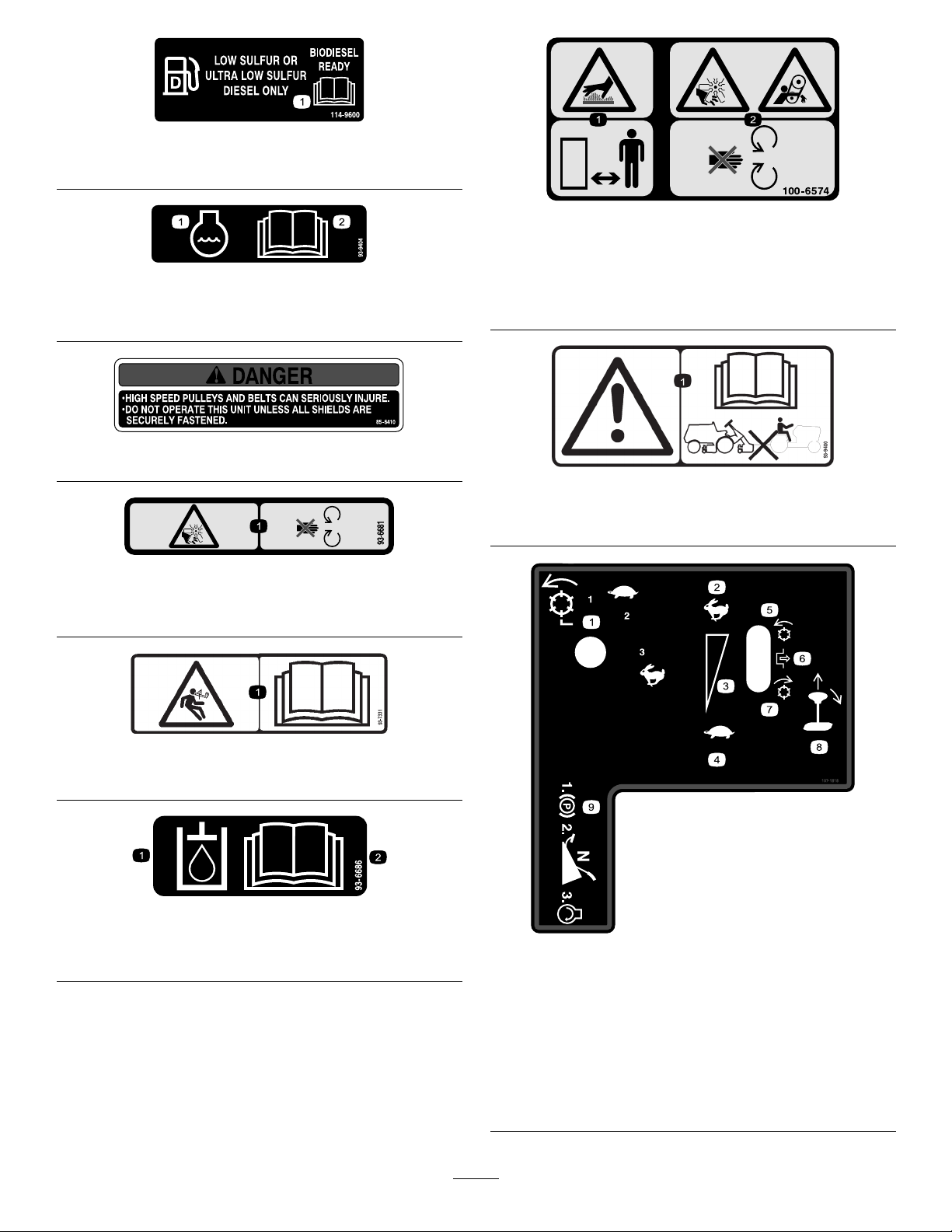
SafetyandInstructionalDecals
Safetydecalsandinstructionsareeasilyvisibletotheoperatorandarelocatednearanyareaof
potentialdanger.Replaceanydecalthatisdamagedorlost.
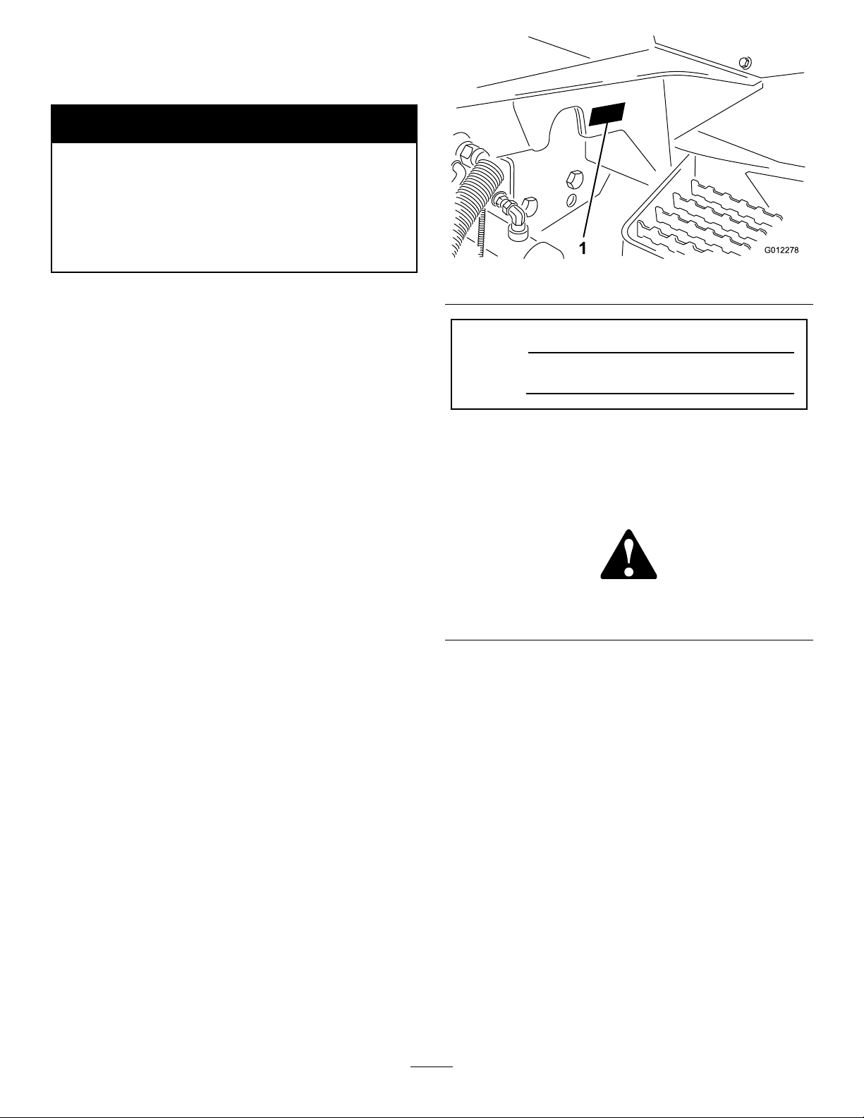
1.Temperaturelevel
2.Fourwheeldriveow
divider
3.On
4.Off
107-1819
5.Engine—stop7.Engine—preheat
6.Engine—start
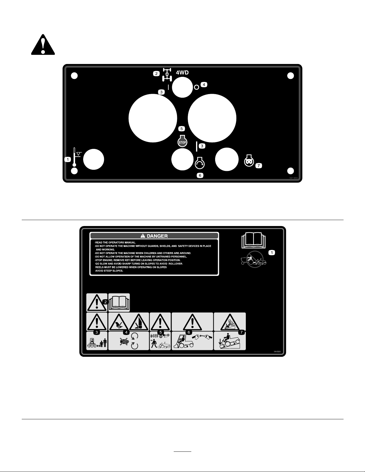
1.ReadtheOperator’s
Manual;donottowthe
machine.
2.Warning—readthe
Operator’sManual.
3.Warning—keepbystanders
asafedistancefromthe
machine.
4.Cuttinghazardofhand
orfoot—stayawayfrom
movingparts.
104-5203
5.Warning—locktheparking
6.Warning—usearollover
8
brake,stoptheengine,and
removetheignitionkey
beforeleavingthemachine.
protectionsystemandwear
theseatbelt.
7.Tippinghazard—lowerthe
cuttingunitwhendriving
downslopes.
Page 9
104-5204forCE
(Afxoverpartno.104–5203forCE*
*ThissafetydecalincludesaslopewarningrequiredonthemachineforcompliancetotheEuropeanLawnMowerSafetyStandardEN836:1997.Theconservativemaximum
slopeanglesindicatedforoperationofthismachineareprescribedbyandrequiredbythisstandard.
1.ReadtheOperator’s
Manual;donottowthe
machine.
2.Warning—readthe
Operator’sManual.
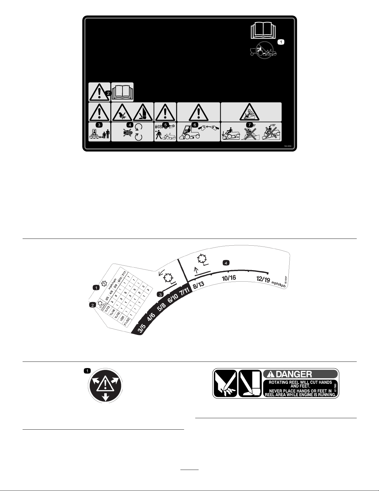
1.7-bladereel
3.Warning—keepbystanders
asafedistancefromthe
machine.
4.Cuttinghazardofhand
orfoot—stayawayfrom
movingparts.
2.Heightofcut
5.Warning—locktheparking
brake,stoptheengine,and
removetheignitionkey
beforeleavingthemachine.
6.Warning—usearollover
protectionsystemandwear
theseatbelt.
93-9397
3.Reel—mowingspeeds4.Reel—transportspeeds
7.Tippinghazard—lowerthe
cuttingunitwhendriving
downslopes.
1.Warning—contentsunderpressure.
59-8440
67-7960
9
Page 10
114-9600
1.ReadtheOperator’sManual.
93-9404
1.Enginecoolant
2.ReadtheOperator’s
Manual.
85-6410
93-6681
1.Cutting/dismemberment—hazard,fan-stayawayfrom
movingparts.
100-6574
1.Hotsurface/burnhazard—stayasafedistancefromthe
hotsurface.
2.Cutting/dismembermenthazard,fanandentanglement
hazard,belt—stayawayfrommovingparts;keepallguards
andshieldsinplace.
93-9400
1.Warning—readtheOperator’sManual;donottowthe
machine.
93-7331
1.Storedenergyhazard—readtheOperator’sManual.
93-6686
1.Hydraulicoil
2.ReadtheOperator’sManual.
1.Reel—mowingspeeds,
slowtofast.
2.Fast7.Reel—backlapping
3.Continuousvariable
setting
4.Fast
5.Reel—mowing
10
107-1818
6.Disengage
8.Pullandmovethelever.
9.Settheparkingbrake,set
thecontrolstoneutral,and
starttheengine.
Page 11
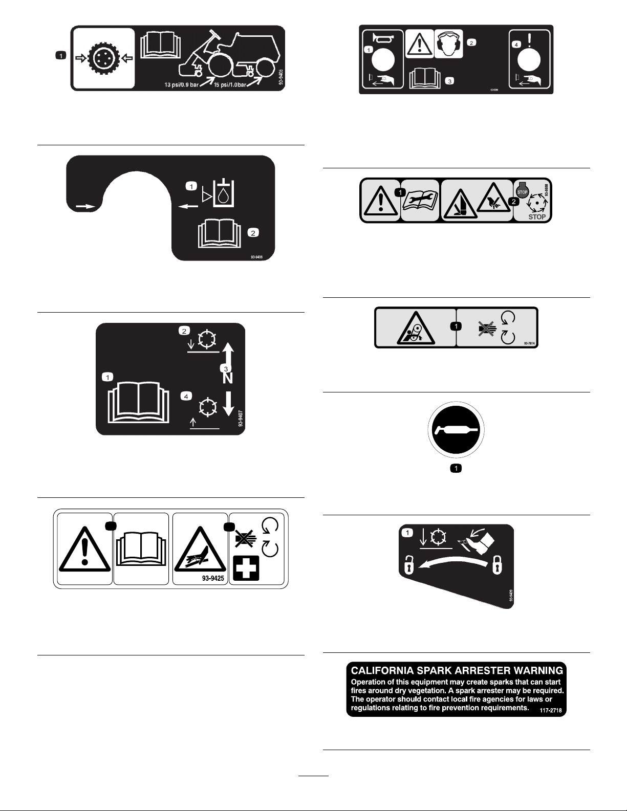
93-9405
2
1
1.Tirepressure—readtheOperator’sManual;llthefront
tiresto13psi(0.9bar)andthereartiresto15psi(1.0bar).
93-9406
1.Hydraulicoillevel
2.ReadtheOperator’s
Manual.
93-9399
1.Horn—pressthebutton.
2.Warning—wearhearing
protection.
3.ReadtheOperator’s
Manual.
4.Failure/malfunction—
pressthebutton.
93-6688
1.Warning—readthe
instructionsbefore
servicingorperforming
maintenance.
2.Cuttinghazardofhandor
foot—stoptheengineand
waitformovingpartsto
stop.
93-7814
1.Entanglementhazard,belt—stayawayfrommovingparts.
93-9407
1.ReadtheOperator’s
Manual.
2.Lowerthereels.4.Raisethereels.
3.Neutral
93-9425
1.ReadtheOperator’sManual.
2.Hydraulichosesareunderpressure—stayawayfrom
movingparts.
58-6520
1.Grease
93-9409
1.Tounlockthereelsbeforeloweringthem,pressthepedal.
117–2718
11
Page 12
ProductOverview
G012285
1
G012493
1
2
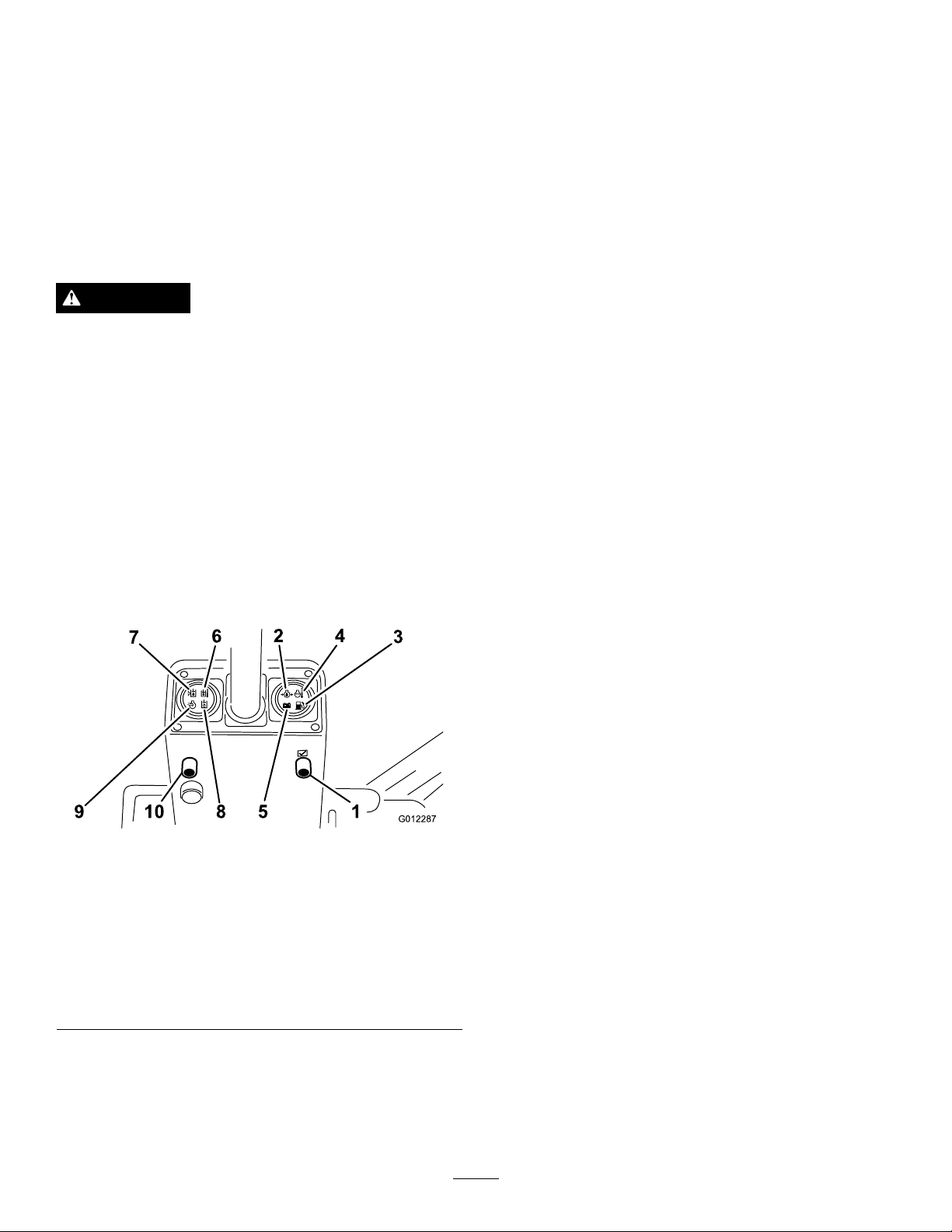
Controls
SeatAdjustingLever
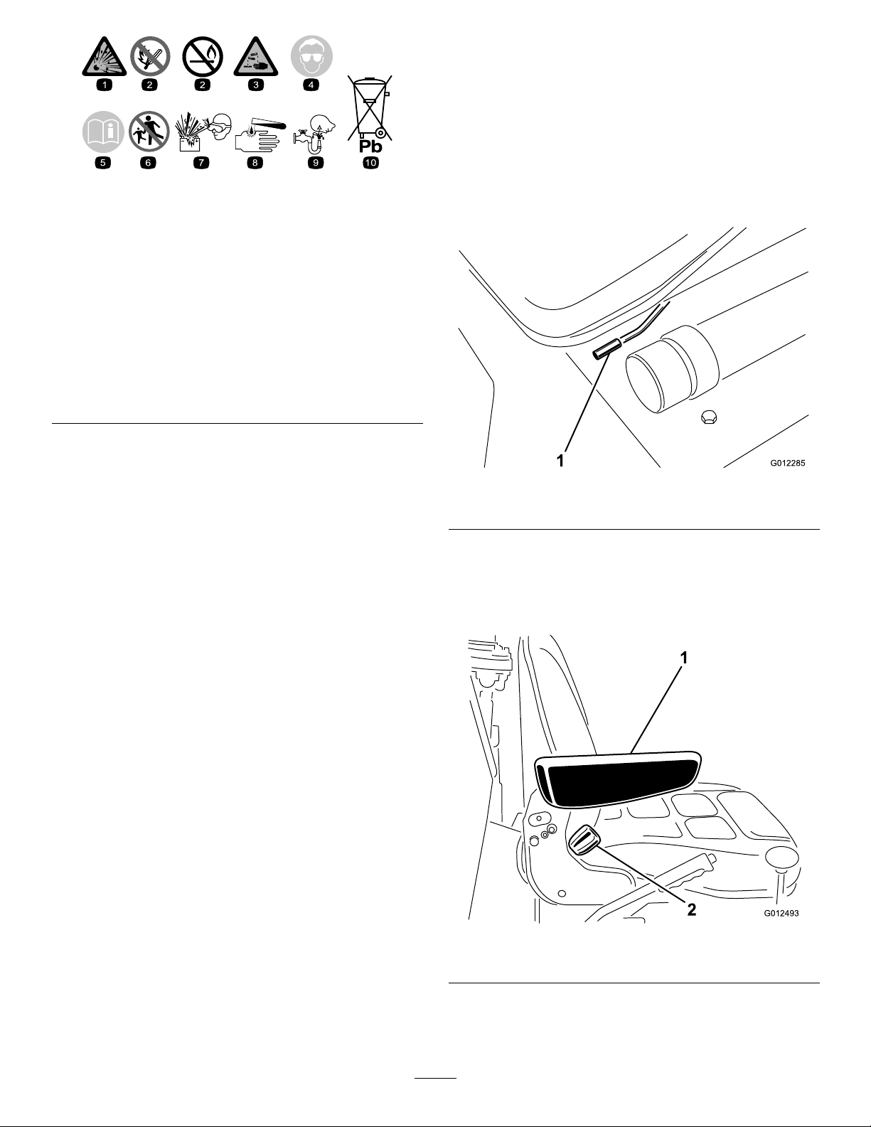
BatterySymbols
Someorallofthesesymbolsareonyourbattery
1.Explosionhazard
2.Nore,opename,or
smoking.
3.Causticliquid/chemical
burnhazard
4.Weareyeprotection9.Flusheyesimmediately
5.ReadtheOperator’s
Manual.
6.Keepbystandersasafe
7.Weareyeprotection;
8.Batteryacidcancause
10.Containslead;donot
Theseatadjustinglever(Figure3)allows5.9inch(15
cm)foreandaftadjustmentin19/32inch(15mm)
increments.
distancefromthebattery .
explosivegasescan
causeblindnessandother
injuries
blindnessorsevereburns.
withwaterandgetmedical
helpfast.
discard.
Figure3
1.Seatadjustinglever
ArmRest
Pivotthearmrest(Figure4)upanddownforoperator
comfort.
Figure4
1.Armrest2.Backrestknob
12
Page 13
BackrestKnob
G01228 7
1589 10
7
6
2 4
3
EngineOilPressureWarning
Thebackrestknob(Figure4)adjustsbackrestangle
from5–20degrees.
SuspensionKnob
Thesuspensionknob,locatedbelowtheseatpan,allows
youtosettheseatfortheweightoftheoperator.
Note:Thebackrestandbottomseatcushionsare
removable.
CAUTION
Toensurethattheinterlockswitchoperates
properly,settheseatsuspensionfortheweightof
eachoperator.Ifthesuspensionisnotsetcorrectly,
theenginewillrunintermittentlyandtendtostall.
Tocorrectthis,setthesuspensionlighter.
WarningLightTestButton
Beforeoperatingmachine,pressthewarninglighttest
button(Figure5).Alllightsonthesteeringtower
shouldilluminate.Anylightthatdoesnotcomeon
indicatesanelectricalmalfunctionthatshouldbe
repairedimmediately.Oilpressureandelectricalno
chargeindicatorlightsilluminatewhenturningthekey
switchOn.
Dangerouslylowengineoilpressureisindicatedbyboth
awarningindicatorlightandaudiblesignal(
Figure5).
Whenthisoccurs,stoptheengineimmediatelyand
correcttheproblem.
FuelSystemWarning
Awarningindicatorlightandaudiblesignal(Figure5)
warnofexcesswaterinthefuelsystem.Removewater
fromthesystem.
CoolantTemperatureWarning
Ifenginecoolanttemperatureexceeds221°F(105°C)a
warningindicatorlight(Figure5)illuminatesandaudible
signalsounds.Theengineshutsdowniftemperature
ofcoolantexceeds230°F(110°C).Switchresets
automaticallywhensystemandenginecoolsdown.
ElectricalNoChargeWarning
Nochargetothebatteriesisindicatedbyawarning
indicatorlightandaudiblesignal(
Figure5).
HydraulicOilTemperatureWarning
Awarningindicatorlightandaudiblesignalwarn
Figure5)ofexcessivelyhighhydraulictemperature.
(
Figure5
1.Warninglighttestbutton6.Hydraulicoiltemperature
2.Engineoilpressure
warninglight
3.Fuelsystemwarning
4.Coolanttemperature
warning
5.Electricalnocharge
warning
warning
7.Hydraulicoillevelwarning
8.Hydraulicoillterwarning
9.Aircleanerwarning
10.Alarmsilencebutton
HydraulicandEngineIndicatorLights
Iftheselightscomeon(Figure5),stopthemachineand
makerepairsimmediately .
HydraulicOilLevelWarning
Awarningindicatorlightandaudiblesignal(Figure5)
warnoflowhydraulicoillevel.Ifoilleveldropsfurther,
theenginewillautomaticallybestopped.Enginecannot
berestarteduntiloilsupplyisbroughttoasafelevel.
HydraulicOilFilterWarning
Awarningindicatorlightandaudiblesignal(Figure5)
warnofacloggedhydrauliclter.
AirCleanerWarning
Awarningindicatorlightandaudiblesignal(Figure5)
warnthatthelteriscloggedandinneedofservice.
AlarmSilenceButton
Pressingbutton(Figure5)silencesalarm.Alarmsystem
willdisengageandautomaticallyresetwhentheproblem
iscorrectedorthealarmsilencebuttonispressed.
TractionPedal
Thetractionpedal(Figure6)controlsforwardand
reverseoperation.Pressthetopofthepedaltomove
13
Page 14
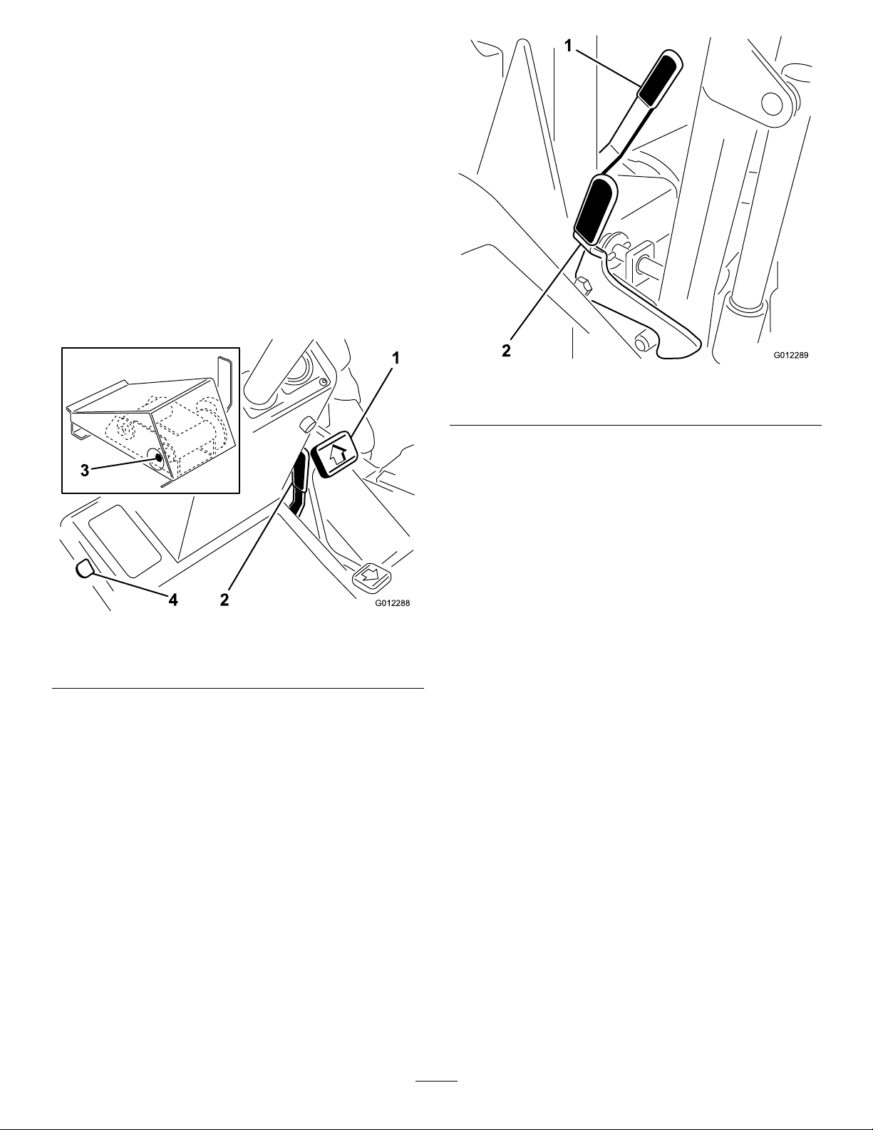
forwardandthebottomtomovebackward.Ground
G012288
4 2
1
3
G012289
1
2
speeddependsonhowfarthepedalispressed.For
maximumgroundspeed,fullypressthepedalwhilethe
throttleisintheFastposition.Formaximumpower
underloadorwhengoinguphill,keeptheenginerpm
highbyhavingthethrottleintheFastpositionandthe
tractionpedalheldstationaryagainstthegroundspeed
limiter.Iftheenginerpmbeginstodecreaseduetoload,
graduallyreducethetractionpedalpressureuntilthe
enginespeedisincreased.
Tostop,reducefootpressureonthetractionpedaland
allowittoreturntothecenterposition.Onextreme
downhillslopes,applypressuretothereversesideofthe
pedal,oroperatewithyourheelontheReverseandtoe
ontheForwardportionofthepedal.
Figure7
1.Centercuttingunitlatch2.Outsidecuttingunitlatch
Figure6
1.Tractionpedal
2.Speedlimiter
3.Camlevernut
4.Transportlatch
GroundSpeedLimiter
Thegroundspeedlimiter(Figure6)controlsthetraction
pedalmovement.Thelimiterleverhelpscontrolthe
rateofclipandeliminatessuddenspeedvariationsover
roughterrain.
Important:Thecamlevernut(
betightenedifthelimiterstopwillnotholdthe
tractionpedalinthedesiredposition.
Figure6,Inset)can
CuttingUnitLiftControls
Thetwooutsidelevers(Figure8)raiseandlowerthetwo
outsidecuttingunits.Thecenterleverraisesandlowers
thetwofrontandthecentercuttingunits.Theengine
mustberunningtolowerthecuttingunits.Whenthe
cuttingunitsarelifted,thereelsautomaticallystop.Do
notallowtheleverstosnapbacktoneutral,orcutting
unitsmaynotoatfreely.
TransportLatches
Theselatchessecurethecuttingunitsintheupright
positionfortransportoperation.Thelatchforthe
frontcuttingunitsisfoot–operated(Figure6).The
hand-operatedlatchescontrolthecenterandoutside
cuttingunits(Figure7).
14
Page 15

G012290
1 2 3 4 5 6
10
11
9 8 7
Figure8
1.Cuttingunitliftcontrols
2.Mow/backlaplever
3.Throttle9.Parkingbrake
4.Engineoverridebutton10.Reelspeedcontrol
5.Fuelgauge
6.Hourmeter
7.Enginepreheatindicator
light
8.Keyswitch
11.4Wheeldriveswitch(4
wheeldriveonly)
KeySwitch
Threepositions:Off,On,andStart.Rotatethekey
Figure8)toStartandreleaseitwhentheenginebegins
(
running.Tostoptheengine,rotatethekeytoOff.
ParkingBrakeLever
Pullthislever(Figure8)uptolockthebrake.Torelease
thebrake,pulluponthelever,pressthebutton,and
lowerthelever.Thebrakemustbeengagedtostartthe
engine.Alwaysengagetheparkingbrakebeforegetting
offoftheseat.
Mow-BacklapLever
Movethislever(Figure8)forwardtoengagethecutting
units.Movethelevertothecentertostopthecutting
units.Tobacklapcuttingunits,lifttheleveroverstop
andholditintherearposition.
Important:Donotmoveleverdirectlybetweenthe
MowandBacklappositions.Pausebrieyinthe
Stopposition.
ReelSpeedControl
EngineOverrideButton
Whenthisbutton(Figure8)ispressed,theenginecan
beoperatedafterithasoverheatedandautomatically
beenstoppedbytheelectricalsafetysystem.Useonly
forshortintervals.
FuelLevelGauge
Gauge(Figure8)indicatestheamountoffuelintank.
HourMeter
Hourmeter(Figure8)indicatesthetotalhoursthat
machinehasbeenoperated.
Note:Linescirclinginthesmallwindowatleftsideof
gaugeindicatehourmeterisoperating.
EnginePreheatIndicatorLight
Thislight(Figure8)turnsonwhenthekeyismovedto
theOnposition.Glowplugsengagefor10seconds,
then,thelightgoesoffwhentheengineisreadytostart.
Rotatetheknob(Figure8)clockwisetoincreasethe
reelspeed,counter–clockwisetodecreasespeed.Usein
conjunctionwiththegroundspeedlimitertoachieve
theappropriaterateofclip.
ThrottleControl
Movethiscontrol(Figure8)forwardtoincreaseengine
speedandbackwardtodecreasespeed.
4WheelDriveSwitch(4wheeldrive
modelonly)
Movethisswitch(Figure8)forwardtoengage4wheel
drive.Moveittotherearpositiontodisengage4wheel
drive.
15
Page 16

Specications
Note:Specicationsanddesignaresubjecttochange
withoutnotice.
Width,cuttingunitsraised
Width,cuttingunitslowered
Widthofcut,5cuttingunits137inches(348cm)
Widthofcut,4cuttingunits110inches(279cm)
Widthofcut,3cuttingunits83inches(211cm)
Widthofcut,1cuttingunit29.5inches(75cm)
Length
HeightwithROPS82inches(208cm)
HeightwithoutROPS55.5inches(141cm)
Weight(Dry)4360lb(1717kg)
Fueltankcapacity
91.5inches(232cm)
147inches(373cm)
110inches(282cm)
15USgallons(56.8l)
Attachments/Accessories
AselectionofToroapprovedattachmentsand
accessoriesareavailableforusewiththemachineto
enhanceandexpanditscapabilities.Contactyour
AuthorizedServiceDealerorDistributororgoto
www.Toro.comforalistofallapprovedattachments
andaccessories.
16
Page 17

Operation
G012279
1
G012280
1
G012281
1
Note:Determinetheleftandrightsidesofthe
machinefromthenormaloperatingposition.
CheckingtheEngineOilLevel
Theengineisshippedwithoilinthecrankcase;
however,theoillevelmustbecheckedbeforeandafter
theengineisrststarted.
Crankcasecapacityisapproximately8qt.(7.6L)with
thelter.
Figure10
1.Dipstick
Usehigh-qualityengineoilthatmeetsthefollowing
specications:
•APIClassicationLevelRequired:CH-4,CI-4or
higher
•Preferredoil:SAE15W-40(above0degreesF)
•Alternateoil:SAE10W -30or5W -30(all
temperatures)
ToroPremiumEngineoilisavailablefromyour
distributorineither15W -40or10W -30viscosity.
1.Parkthemachineonalevelsurface,stoptheengine,
settheparkingbrake,andremovethekeyfromthe
ignitionswitch.
2.Releasetheenginecoverlatchesandopenthehood.
4.Removedipstickandcheckoillevelondipstick.
TheoillevelshouldbeuptotheFullmark.
5.IftheoillevelisbelowtheFullmark,removethe
llcap(
Figure11)andaddoiluntillevelreaches
theFullmarkondipstick.
Donotoverll.
Figure11
1.Oilllcap
Important:Besuretokeeptheengineoillevel
betweentheupperandlowerlimitsontheoil
gauge.Enginefailuremayoccurasaresultof
overllingorunderllingtheengineoil.
Figure9
1.Enginecoverlatch
3.Removethedipstick,wipeitclean,andinstallit
(Figure10).
6.Installtheoilllcap.
7.Closeenginecoverandsecurewiththelatches.
CheckingtheCoolingSystem
ServiceInterval:Beforeeachuseordaily
Capacityofsystemis3.7USgallons(14L).
1.Carefullyremovetheradiatorcap(Figure13)and
expansiontankcap(Figure12).
17
Page 18

CAUTION
G012282
1
Iftheenginehasbeenrunning,thepressurized,
hotcoolantcanescapeandcauseburns.
•Donotopentheradiatorcapwhenthe
engineisrunning.
•Usearagwhenopeningtheradiatorcap,
andopenthecapslowlytoallowsteamto
escape.
wintergradefuelatlowertemperaturesprovideslower
ashpointandcoldowcharacteristicswhichwillease
startingandreducefuellterplugging.
Useofsummergradefuelabove20°F(-7°C)will
contributetowardlongerfuelpumplifeandincreased
powercomparedtowintergradefuel.
Important:Donotusekeroseneorgasoline
insteadofdieselfuel.Failuretoobservethis
cautionwilldamagetheengine.
2.Checklevelofcoolantinradiator.Radiator
shouldbelledtothetopofthellerneckand
theexpansiontanklledtothemarksonitsside
Figure12).
(
Figure12
1.Expansiontank
WARNING
Fuelisharmfulorfatalifswallowed.Long-term
exposuretovaporscancauseseriousinjuryand
illness.
•Avoidprolongedbreathingofvapors.
•Keepfaceawayfromnozzleandgastankor
conditioneropening .
•Keepfuelawayfromeyesandskin.
BiodieselReady
Thismachinecanalsouseabiodieselblendedfuel
ofuptoB20(20%biodiesel,80%petrodiesel).The
petrodieselportionshouldbeloworultralowsulfur.
Observethefollowingprecautions:
•Thebiodieselportionofthefuelmustmeet
specicationASTMD6751orEN14214.
•TheblendedfuelcompositionshouldmeetASTM
D975orEN590.
3.Ifthecoolantlevelislow,adda50/50mixture
ofwaterandethyleneglycolanti–freeze.Donot
overll.
Important:Donotusewateronlyor
alcohol/methanolbasecoolants.
4.Installtheradiatorandexpansiontankcaps.
AddingFuel
Useonlyclean,freshdieselfuelorbiodieselfuelswith
low(<500ppm)orultralow(<15ppm)sulfurcontent.
Theminimumcetaneratingshouldbe40.Purchase
fuelinquantitiesthatcanbeusedwithin180daysto
ensurefuelfreshness.
Fueltankcapacity:15USgallons(56.8L)
Usesummergradedieselfuel(No.2-D)attemperatures
above20°F(-7°C)andwintergrade(No.1-Dor
No.1-D/2-Dblend)belowthattemperature.Useof
•Paintedsurfacesmaybedamagedbybiodiesel
blends.
•UseB5(biodieselcontentof5%)orlesserblends
incoldweather.
•Monitorseals,hoses,gasketsincontactwithfuelas
theymaybedegradedovertime.
•Fuellterpluggingmaybeexpectedforatimeafter
convertingtobiodieselblended.
•Contactyourdistributorifyouwishformore
informationonbiodiesel.
18
Page 19

DANGER
G012283
2
1
Undercertainconditions,dieselfuelandfuel
vaporsarehighlyammableandexplosive.Are
orexplosionfromfuelcanburnyouandothersand
cancausepropertydamage.
•Useafunnelandllthefueltankoutdoors,
inanopenarea,whentheengineisoffandis
cold.Wipeupanyfuelthatspills.
•Donotllthefueltankcompletelyfull.Add
fueltothefueltankuntilthelevelis1inch
(25mm)belowthebottomofthellerneck.
Thisemptyspaceinthetankallowsthefuelto
expand.
•Neversmokewhenhandlingfuel,andstay
awayfromanopenameorwherefuelfumes
maybeignitedbyaspark.
•Neversmokewhenhandlingfuel,andstay
awayfromanopenameorwherefuelfumes
maybeignitedbyaspark.
•Storefuelinaclean,safety-approvedcontainer
andkeepthecapinplace.
Figure13
1.Radiatorcap2.Fueltankcap
4.Fillthetankuntilthelevelistothebottomofthe
llerneckwithdieselfuel.
5.Installfueltankcaptightlyafterllingtank.
Note:Ifpossible,llthefueltankaftereachuse.
Thiswillminimizepossiblebuildupofcondensation
insidethefueltank.
DANGER
Incertainconditionsduringfueling,static
electricitycanbereleasedcausingasparkwhich
canignitethefuelvapors.Areorexplosionfrom
fuelcanburnyouandothersandcandamage
property.
•Alwaysplacefuelcontainersontheground
awayfromyourvehiclebeforelling .
•Donotllfuelcontainersinsideavehicleoron
atruckortrailerbedbecauseinteriorcarpets
orplastictruckbedlinersmayinsulatethe
containerandslowthelossofanystaticcharge.
•Whenpractical,removeequipmentfromthe
truckortrailerandrefueltheequipmentwith
itswheelsontheground.
•Ifthisisnotpossible,thenrefuelsuch
equipmentonatruckortrailerfromaportable
container,ratherthanfromafueldispenser
nozzle.
•Ifafueldispensernozzlemustbeused,keep
thenozzleincontactwiththerimofthefuel
tankorcontaineropeningatalltimesuntil
fuelingiscomplete.
1.Parkthemachineonalevelsurface.
2.Usingacleanrag,cleanareaaroundfueltankcap.
3.Removecapfromthefueltank(Figure13).
Checking/AddingHydraulic
Fluid
Thehydraulicsystemandreservoirislledatthefactory
withapproximately18.2USgallons(69L)ofhigh
qualityhydraulicuid.Thehydraulicuidreservoir
holds9.3USgallons(35.2L)ofthetotal.Checkthe
levelofthehydraulicuidbeforetheengineis
rststartedanddailythereafter.Therecommended
replacementuidisasfollows:
ToroPremiumAllSeasonHydraulicFluid(Availablein5
gallonpailsor55gallondrums.SeepartscatalogorToro
distributorforpartnumbers.)
Alternateuids:IftheTorouidisnotavailable,other
uidsmaybeusedprovidedtheymeetallthefollowing
materialpropertiesandindustryspecications.Wedo
notrecommendtheuseofsyntheticuid.Consult
withyourlubricantdistributortoidentifyasatisfactory
product.
Note:Torowillnotassumeresponsibilityfordamage
causedbyimpropersubstitutions,souseonlyproducts
fromreputablemanufacturerswhowillstandbehind
theirrecommendation.
Anti-wearHydraulicFluid,ISOVG46
MaterialProperties:
Viscosity,ASTMD445cSt@40°C65to71
cSt@100°C8.4to8.9
19
Page 20

ViscosityIndexASTM
G012284
1
G012313
1
D2270
PourPoint,ASTMD97-18°Fto-30°F
IndustrySpecications:
VickersI-286-S(QualityLevel),VickersM-2950-S
(QualityLevel),DenisonHF-0
97to107
C.Removecoverandaddhydraulicoiluntilitis
evenwitharrowsonsightglass(Figure14).
CheckingtheReeltoBedknife
Note:Manyhydraulicuidsarealmostcolorless,
makingitdifculttospotleaks.Areddyeadditive
forthehydraulicsystemoilisavailablein2/3oz(20
ml)bottles.Onebottleissufcientfor4–6USgallons
(15-22L)ofhydraulicoil.Orderpartnumber44-2500
fromyourauthorizedTorodistributor.
1.Parkthemachineonalevelsurface.
2.Lookintothesightglass(
Figure14).Theoillevel
shouldbeevenwiththearrowswhenchecking
warmoil.Theoilwillbe1/4to1/2inch(6to12
mm)belowthearrowswhencold.
Contact
Eachdaybeforeoperating,checkreeltobedknife
contact,regardlessifthequalityofcuthadpreviously
beenacceptable.Theremustbelightcontactacross
thefulllengthofthereelandthebedknife(referto
AdjustingtheReeltoBedknifeinthecuttingunit
Operator’sManual).
CheckingtheTirePressure
Fornormalmowingconditionsandawidevarietyof
turfgrasses,usethesetirepressures:13psi(90kPa)
frontand15psi(103.4kPa)rear.However,whenturf
iseitherwetterordrierthannormal,tirepressure
mayneedtobechanged.Onhardturf,usehightire
pressure(18psi(124kPa)frontandrear).Whenturf
issoft,uselowpressure(9psi(62kPa)frontand12
psi(82.7kPa)rear).
Important:Maintainevenpressureintwofront
tires,i.e.,13psi(90kPa)andbothreartires,i.e.,15
psi(103.4kPa),toensureexcellentquality-of-cut.
Figure14
1.Sightglassarrows
3.Iftheoillevelislow ,addhydraulicoiltothe
reservoir,asfollows:
A.Removetheseatlockpin,raisetheseatandhold
itopenwiththesupportrod.
B.Cleanaroundreservoircover(Figure15).
Figure15
1.Reservoircover
RearBallast
ThisunitcomplieswiththeANSIB71.4–2004Standard
whenreartiresarelledwithcalciumchlorideandarear
wheelweightkit(PartNumber11-0440)isinstalled.
Important:Ifapunctureoccursinatirewith
calciumchloride,removeunitfromturfareaas
quicklyaspossible.T opreventpossibledamageto
turf,immediatelysoakaffectedareawithwater.
StartingandStopping
1.Sitontheseat,keepyourfootoffofthetraction
pedal.Ensurethattheparkingbrakeisengaged
Andthatthetractionpedalandmow/backlaplever
areinneutral.
2.TurnthekeyswitchtotheOnposition.Whenthe
glowplugindicatorlightgoesoff,theengineis
readytoStart.
3.TurnthekeytotheStartposition.Releasethekey
whentheenginestarts.
Tostop,disengageandmoveallcontrolstoneutraland
settheparkingbrake.Raiseandlatchallcuttingunits
20
Page 21

inthetransportposition.TurnthekeytotheOffand
G012391
1
2
G012291
1
G012292
1
removeitfromtheswitch.
BleedingtheFuelSystem
1.Parkthemachineonalevelsurface.Ensurethatthe
fueltankisatleasthalffull.
2.Raisetheenginecover.
3.Opentheventplugonthefuellter/water
separator(
Figure16).
bleedscrew.LeavethekeyintheOnpositionuntil
asolidstreamoffuelowsoutaroundthescrew .
TightenthescrewandturnthekeytotheOff
position.
Note:Normally,theengineshouldstartafter
performingtheabovebleedingprocedures.
However,ifenginedoesnotstart,airmaybe
trappedbetweentheinjectionpumpandthe
injectors;refertoBleedingAirfromtheInjectors.
CheckingtheWarning
IndicatorLights
Eachdaybeforeoperating,ensurethatallwarning
lightsareworking.
Note:Analarmwillcontinuetosounduntilaproblem
iscorrectedoruntilyoupressthealarmsilencebutton.
Ifyouencounterasecondproblem,thealarmwillnot
soundbuttheindicatorlightwillilluminate.
Figure16
1.Fuellter/waterseparator
2.Ventplug
4.TurnthekeyintheignitionswitchtotheOn
position.Theelectricfuelpumpwillbegin
operation,therebyforcingairoutaroundthevent
plug.LeavethekeyintheOnpositionuntilasolid
streamoffuelowsoutaroundplug.Tightenthe
plugandturnkeytotheOffposition.
5.Opentheairbleedscrewonthefuelinjectionpump
Figure17).
(
Figure18
1.Warningindicatorlighttestbutton
CheckingtheSafetyInterlock
System
CAUTION
Ifthesafetyinterlockswitchesaredisconnectedor
damaged,themachinecouldoperateunexpectedly
causingpersonalinjury.
Figure17
1.Fuelinjectionpumpbleedscrew
6.TurnthekeyintheignitionswitchtotheOn
position.Theelectricfuelpumpwillbegin
operation,therebyforcingairoutaroundtheair
•Donottamperwiththeinterlockswitches.
•Checktheoperationoftheinterlockswitches
dailyandreplaceanydamagedswitchesbefore
operatingthemachine.
1.Inawideopenareafreeofdebrisandbystanders,
lowerthecuttingunitstotheground.Stopthe
engine.
21
Page 22

2.Sitontheseatandengagetheparkingbrake.
G012293
1
G012294
1
Turnthekeyandtrytostarttheenginewith
theMow-BacklapleverinboththeMowand
Backlappositions.Iftheenginecranks,thereisa
malfunctionthatmustberepairedimmediately.If
enginedoesnotcrank,thecuttingunitdriveswitch
isoperatingproperly.
3.Sitontheseatanddisengagetheparkingbrake.
Turnthekeyandtrytostartenginewiththe
Mow-BacklapleverintheStopposition.Ifthe
enginecranks,thereisamalfunctionthatmustbe
repairedimmediately.Ifenginedoesnotcrank,the
brakeswitchisoperatingproperly.
4.Engagetheparkingbrake,starttheengine,and
lowerthecuttingunits.MovetheMow-Backlap
levertotheMowposition.Raiseofftheseat;the
engineshouldstopwithinafewseconds,which
indicatestheinterlocksystemisoperating.Alsoraise
offtheseatwiththeleverintheBacklapposition.
Theengineshouldstop,indicatinginterlocksystem
isoperating.Ifenginedoesnotstop,thereisa
malfunctionthatmustberepairedimmediately.
Figure19
1.Retainerclip
2.Raisetheseatandsupportitinanduprightposition
withtheseatsupportrod(Figure20).
Note:Thereisa1to2seconddelaybetweenrising
offtheseatandengineshuttingoff.
5.Engagetheparkingbrake,movetheMow-Backlap
levertotheNeutralposition,starttheengine,
disengagetheparkingbrake,andraiseofftheseat.
Iftheenginestops,theinterlocksystemisoperating.
Ifenginedoesnotstop,thereisamalfunctionthat
mustberepairedimmediately .
PushingorTowingthe
Machine
Inanemergency,themachinecanbepushedortowed
foraveryshortdistance,byusingthetractionpump
by–passvalve.
Important:Donotpushortowthemachinefaster
than2-3mph(3-4.8km/h)becausethehydraulic
systemmaybedamaged.Ifthetractionunitmust
bemovedaconsiderabledistance,transportitona
truckortrailer.
Figure20
1.Seatsupportrod
3.Rotatetheby-passvalve90degrees(Figure21).
Openingthevalveopensaninternalpassageinthe
tractionpump,therebyby-passinghydraulicoil.
Becauseoilisby-passed,thetractionunitcanbe
movedwithoutdamagingthehydraulicsystem.
DANGER
Themachinewillrollwiththefrontwheelmotors
disengaged.Themachinemustbeonalevel
surfaceorthewheelsmustbeblocked.There
isnoeffectivebrakingwiththewheelmotors
disengaged.
1.Removetheretainerclipfromtheseatlockrod
(Figure19).
22
Page 23

G012295
1
Figure21
G0122961
MowingPreparation
Whenyouareattheareatobemowed,releasethe
front,centerandoutsidecuttingunittransportlatches,
lowerthecuttingunits,engagetheparkingbrake,and
stoptheengine.
CuttingUnitGrassDeectors
Adjustgrassdeectorstothehorizontalposition
Figure22),sotheclippingsdispersebackward;outand
(
awayfromthecuttingunits.Thiswillpreventclumps
ofclippings,especiallywetclippings,droppingoff
themachineorcuttingunits,whichaffectsthevisual
appearanceoftheturf.
Important:Ensurethattheparkingbrakeis
engagedbeforeopeningtheby-passvalve.
4.Beforestartingtheengine,closetheby-passvalve.
Donotstarttheenginewhenthevalveisopen.
Important:Runningthemachinewiththe
by-passvalveopenwillcausethehydraulic
systemtooverheat.
OperatingTips
Familiarization
Beforemowinggrasspracticeoperatinginanopen
area.Startandstoptheengine.Operateinforwardand
reverse.Lowerandraisecuttingunitssimultaneously
andindividually.Engageanddisengagereels.Operate
withallcuttingunitsdown,thenwithonlyanindividual
cuttingunit.Whenyoufeelfamiliarwiththemachine,
practiceoperatingaroundtreesandobstacles.Also
driveupanddownslopesusingbothmowingand
transportspeeds.
DANGER
Note:Generallyyoucanadjustthedeectorsdown
slightlyindrygrassandupslightlyinwetgrass.
Figure22
1.Grassdeector
Mowing
Matchthegroundspeedlimiter(Figure23)andreel
speedcontrolknob(Figure24)todesiredheight-of-cut;
refertoCuttingChartinMatchingtheGroundSpeed
andReelSpeed.Usethedecalatthesideofthesteering
columnasaguideonly.
Whenoperatingthemachine,alwaysusetheseat
beltandROPStogether.Donotuseaseatbelt
withoutaROPS.
WarningSystem
Ifawarninglightcomesonduringoperation,stopthe
machineimmediatelyandcorrecttheproblembefore
continuingoperation.Seriousdamagecouldoccurif
themachineisoperatedwithamalfunction.Forshort
intervals,however,theemergencyengineoverride
buttoncanbeusedtooperatetheengineifitstops
becauseofoverheating.
23
Page 24

G012297
1
2
1.Groundspeedlimiter
G012298
1
Figure23
2.Tractionpedal
backuntilthecuttingunitsarefullyraised(asqueal
fromthehydraulicsystemmeansthecuttingunitsare
fullyraised).Lockthecuttingunitsinplacewiththe
transportlatches.Becarefulwhendrivingbetween
objectssoyoudonotaccidentallydamagethemachine
orcuttingunits.
MatchingGroundSpeedandReel
Speed
Varyreelspeed(whilemaintainingconstantground
speed)toestablishthebestqualityofcutforthearea
beingmowed.Reelspeedseithertoofastortooslow
forconditionsmayeffectthequalityofcut.Usethe
appropriatecuttingchart(below)andthedecalon
steeringconsoleasaguideforinitialadjustmentof
groundandreelspeeds.
RelateHOCandgroundspeedtorequiredreelspeed
settingona1thru5scaleonreelspeedknob.
Note:1=800RPM;2=900RPM;3=1000RPM;
4=1100RPM;and5=1200RPM.(Speedsare
approximate)
Figure24
1.Reelspeedcontrol
StarttheengineandmovethethrottletotheFast
position.Disengagetheparkingbrake.Tomove
forward,pressthetractionpedalforward(
Figure23).
MovetheMow-BacklaplevertotheMowposition.The
reelsarenowspinning.Maintaintractionpedalcontact
withthegroundspeedlimiter(Figure23)toensure
consistentclipandquality-of-cut.
CAUTION
Thisproductmayexceednoiselevelsof85dB(A)
attheoperatorposition.Earprotectorsare
recommendedforprolongedexposuretoreduce
thepotentialofpermanenthearingdamage.
Transport
Whenmowingiscomplete,movetheMow-Backlap
levertotheStopposition.Raisethecuttingunitsby
pullingbackontheliftcontrollevers.Holdthelevers
Note:Inthefollowingtables,N/RmeansNot
Recommended.
Note:Positions4and5areonlyattainablewitha
specialcoupler(PartNumber58-1530).Contactyour
ToroDealerforinformation.
RecommendedReelSpeedSettings:5BladeReel
HOC
113
1.25
1.5
2
2.5
RecommendedReelSpeedSettings:7BladeReel
HOC
1/2
5/8
3/4N/R
1
1.25
RecommendedReelSpeedSettings:11BladeReel
34
N/R
N/RN/R
N/RN/RN/R
N/RN/RN/RN/R
34
2
13
N/RN/R
N/RN/RN/R
GroundSpeedInMPH
5
5
13
234
GroundSpeedInMPH
5
5
13
N/RN/RN/R
5
123
6
N/RN/R
5
12
6
N/RN/R
5
12
7
N/R
1
7
N/R
24
Page 25

RecommendedReelSpeedSettings:11BladeReel
(cont'd.)
HOC
3/8
1/2N/R
5/8N/RN/R
3/4N/RN/RN/R
34
13
GroundSpeedInMPH
134
5
5
124
6
N/RN/R
12
7
N/R
25
Page 26

Maintenance
Note:Determinetheleftandrightsidesofthemachinefromthenormaloperatingposition.
RecommendedMaintenanceSchedule(s)
MaintenanceService
Interval
Aftertherst10hours
Aftertherst50hours
Beforeeachuseordaily
Every50hours
MaintenanceProcedure
•Checkthefanandalternatorbelttension.
•T orquethewheellugnuts.
•Changetheengineoilandlter.
•Checktheplanetarygeardriveoillevel.
•Changethehydrauliclter.
•Lubricatethereelspeedvalvewithoil.
•ChecktheengineRPM(idleandfullthrottle).
•Checktheengineoillevel.
•Checkthelevelofthecoolantinthecoolingsystem.
•Checkthehydraulicuidlevel.
•Checkthereeltobedknifecontact.
•Checkthewarningindicatorlights.
•Checkthesafetyinterlocksystem.
•Drainthefuellter/waterseparator.
•Removedebrisfromthescreen,oilcoolers,andradiator(morefrequentlyindirty
operatingconditions).
•Checkthehydrauliclinesandhosesforleaks,kinkedlines,loosemountingsupports,
wear,loosettings,weatherdeterioration,andchemicaldeterioration.
•Greasethebearingsandbushings.(Greasethemimmediatelyaftereverywashing
regardlessoftheintervallisted.)
•Checktheconditionofandcleanthebattery .
•Checkthebatterycableconnections.
Every100hours
Every150hours
Every200hours
Every400hours
Every800hours
Every1,500hours
Beforestorage
•Inspectthecoolingsystemhoses.
•Checktheconditionandtensionofthealternatorbelt.
•Drainwaterfromthehydraulicreservoir.
•Changetheengineoilandlter.
•Servicetheaircleaner.(Morefrequentlyinextremelydirtyordustyconditions)
•T orquethewheellugnuts.
•Drainmoisturefromthefuelandhydraulicuidtanks.
•Checkthecuttingunitreeldrivebelts.
•Checkthefuellinesandconnectionsfordeterioration,damage,orlooseconnections.
•Replacethefuelltercanister.
•ChecktheengineRPM(idleandfullthrottle).
•Drainandcleanthefueltank
•Checktherearwheeltoe-in.
•Checktheplanetarygeardriveoillevel.
•Flushandreplacethecoolingsystemuid.
•Changethehydrauliclter.
•Changethehydraulicsystembreather.(Moreofteninextremelydustyordirty
conditions)
•Packtherearwheelbearings
•Adjusttheenginevalves(refertotheengineOperator’sManual)
•Changethehydraulicuid.
•Drainandcleanthefueltank
Every2years
•Replaceallmovinghoses.
26
Page 27

DailyMaintenanceChecklist
Duplicatethispageforroutineuse.
Fortheweekof: MaintenanceCheckItem
Mon.Tues.Wed.Thurs.Fri.
Checkthesafetyinterlockoperation.
Checkthebrakeoperation.
Checktheengineoilandfuellevel.
Checkcoolingsystemuidlevel.
Drainthewater/fuelseparator .
Checktheairlterrestrictionindicator.
Checktheradiator ,oilcooler ,andscreenfordebris.
Cleantractionpedallockout
Checkunusualenginenoises.
Checkunusualoperatingnoises.
Checkthehydraulicsystemoillevel.
Checkhydraulichosesfordamage.
Checkforuidleaks.
Checkthetirepressure.
Checktheinstrumentoperation.
Checkwarninglampsoperation
Checkthereel-to-bedknifeadjustment.
Checktheheight-of-cutadjustment.
Lubricateallgreasettings.
Touch-updamagedpaint.
1.Checktheglowplugandinjectornozzlesifhardstarting,excesssmoke,orroughrunningisnoted.
1
2
Sat.Sun.
2.Immediatelyaftereverywashing,regardlessoftheintervallisted
CAUTION
Ifyouleavethekeyintheignitionswitch,someonecouldaccidentlystarttheengineandseriouslyinjure
youorotherbystanders.
Removethekeyfromtheignitionbeforeyoudoanymaintenance.
Lubrication
Thegreasettinglocationsandquantitiesareasfollows:
•Liftarms(5)(
Figure25)
GreasingtheBearingsand
Bushings
Ifyouoperatethemachineundernormalconditions,
lubricateallgreasettingsforthebearingsandbushings
afterevery50hoursofoperationwithNo.2General
PurposeLithiumBaseGrease.Lubricatebearingsand
bushingsimmediatelyaftereverywashing,regardless
oftheintervallisted.
27
Page 28

G012299
Figure25
G012300
G012301
G012302
•Rearaxle(6)(Figure26)
Figure27
•Cuttingunitreelandrollerbearings(Figure28)
Figure26
•Floatingorxedheadkitpivots(Figure27)
Figure28
•Reelcontrolvalve(notshown),locatedunderright
handconsole.
28
Page 29

EngineMaintenance
G012303
1 2
G01230 4
1 2
G012305
1
ServicingtheAirCleaner
ServiceInterval:Every200hours(Morefrequentlyin
extremelydirtyordustyconditions)
Checktheaircleanerbodyfordamagewhichcould
causeanairleak.Replaceifdamaged.Checkthewhole
intakesystemforleaks,damageorloosehoseclamps.
Changingtheairlterbeforeitisnecessaryonly
increasesthechanceofdirtenteringtheenginewhen
thelterisremoved.
Important:Besurethecoverisseatedcorrectly
andsealswiththeaircleanerbody.
1.Removetheknobssecuringtherearscreentothe
frame(
Figure29).Removethescreen.
3.Removethecoverfromtheaircleanerbody.Before
removingthelter,uselowpressureair(40psi,
cleananddry)tohelpremovelargeaccumulations
ofdebrispackedbetweentheoutsideofthelter
andthecanister.Avoidusinghighpressureair
whichcouldforcedirtthroughthelterintothe
intaketract.
Thiscleaningprocesspreventsdebrisfrommigrating
intotheintakewhentheprimarylterisremoved.
4.Removeandreplacetheprimarylter.
Cleaningoftheusedelementisnotrecommended
duetothepossibilityofdamagetotheltermedia.
Inspectthenewlterforshippingdamage,checking
thesealingendofthelterandthebody.Donot
useadamagedelement.Insertthenewlterby
applyingpressuretotheouterrimoftheelementto
seatitinthecanister.Donotapplypressuretothe
exiblecenterofthelter.
5.Cleanthedirtejectionportlocatedintheremovable
cover.Removetherubberoutletvalvefromthe
cover,cleanthecavityandreplacetheoutletvalve.
Figure29
1.Rearscreen2.Knob
2.Releasethelatchessecuringtheaircleanercoverto
theaircleanerbody(Figure30).
6.Installthecoverorientingtherubberoutletvalvein
adownwardposition—betweenapproximately5:00
to7:00whenviewedfromtheend.
7.SecurethelatchesAndreplaceandsecuretherear
screen.
ChangingtheEngineOiland
Filter
ServiceInterval:Aftertherst50hours
Every150hours
1.Removethedrainplug(Figure31)andlettheoil
owintoadrainpan.
Figure30
1.Aircleanerbody2.Aircleanercover
Figure31
1.Oildrainplug
2.Whentheoilstops,installthedrainplug.
29
Page 30

3.Removetheoillter(Figure32).
G012306
1
FuelSystem
Maintenance
DANGER
Undercertainconditions,dieselfuelandfuel
vaporsarehighlyammableandexplosive.Are
orexplosionfromfuelcanburnyouandothersand
cancausepropertydamage.
•Useafunnelandllthefueltankoutdoors,in
anopenarea,whentheengineisoffandiscold.
Wipeupanyfuelthatspills.
Figure32
1.Oillter
4.Applyalightcoatofcleanoiltothenewlterseal.
5.Installthereplacementoilltertothelteradapter.
Turntheoillterclockwiseuntiltherubbergasket
contactsthelteradapter,thentightenthelteran
additional1/2turn.
Important:Donotover-tightenthelter.
6.Addoiltothecrankcase;refertoCheckingthe
EngineOilin
Operation(page17).
•Donotllthefueltankcompletelyfull.Add
fueltothefueltankuntilthelevelis1/4to1/2
in.(6to13mm)belowthebottomoftheller
neck.Thisemptyspaceinthetankallowsthe
fueltoexpand.
•Neversmokewhenhandlingfuel,andstayaway
fromanopenameorwherefuelfumesmaybe
ignitedbyaspark.
•Storefuelinaclean,safety-approvedcontainer
andkeepthecapinplace.
DrainingtheFuelTank
ServiceInterval:Every800hours
Beforestorage
Drainandcleanthefueltankifthefuelsystembecomes
contaminatedorifthemachineistobestoredforan
extendedperiod.Usecleanfueltoushoutthetank.
CheckingtheFuelLinesand
Connections
ServiceInterval:Every400hours/Yearly(whichever
comesrst)
Inspectthefuellinesfordeterioration,damage,orloose
connections.
DrainingtheFuelFilter/Water
Separator
ServiceInterval:Beforeeachuseordaily
1.Placeacleancontainerunderthefuellter
(Figure33).
2.Loosenthedrainplugonthebottomofthelter
canisterandallowittodrain.
30
Page 31

G012390
1
2
Figure33
G012307
1
1.Waterseparatorltercanister
3.Tightenthedrainplug.
ReplacingtheFuelFilter
Canister
ServiceInterval:Every400hours
1.Cleantheareawheretheltercanistermounts
Figure33).
(
2.Removetheltercanisterandcleanthemounting
surface.
3.Lubricatethegasketontheltercanisterwithclean
oil.
4.Installthenewltercanisterbyhanduntilthe
gasketcontactsmountingsurface,thenrotateitan
additional1/2turn.
Figure34
1.Fuelinjectors
2.MovethrottletotheFastposition.
3.TurnthekeyinthekeyswitchtotheStartposition
andwatchthefuelowaroundtheconnector.The
enginewillcrank.Whenyouobserveasolidowof
fuel,turnthekeytotheOffposition.
4.Tightenthepipeconnectorsecurely.
5.Repeatsteps1through4ontheremainingnozzles.
BleedingAirfromtheFuel
Injectors
Note:Thisprocedureshouldbeusedonlyifthe
fuelsystemhasbeenpurgedofairthroughnormal
primingproceduresandtheenginewillnotstart;refer
toBleedingtheFuelSysteminOperation(page17).
1.LoosenthepipeconnectiontotheNo.1nozzleand
holderassembly(Figure34).
31
Page 32

ElectricalSystem
Maintenance
Important:Beforeweldingonthemachine,
disconnectbothcablesfromthebattery,bothwire
harnessplugsfromtheelectroniccontrolmodule,
andtheterminalconnectorfromthealternatorto
preventdamagetotheelectricalsystem.
ServicingtheBattery
WARNING
WARNING
Batteryterminalsormetaltoolscouldshortagainst
metaltractorcomponentscausingsparks.Sparks
cancausethebatterygassestoexplode,resulting
inpersonalinjury.
•Whenremovingorinstallingthebattery,donot
allowthebatteryterminalstotouchanymetal
partsofthemachine.
•Donotallowmetaltoolstoshortbetween
thebatteryterminalsandmetalpartsofthe
machine.
CALIFORNIA
Proposition65Warning
Batteryposts,terminals,andrelated
accessoriescontainleadandleadcompounds,
chemicalsknowntotheStateofCalifornia
tocausecancerandreproductiveharm.
Washhandsafterhandling.
DANGER
Batteryelectrolytecontainssulfuricacidwhichisa
deadlypoisonandcausessevereburns.
•Donotdrinkelectrolyteandavoidcontactwith
skin,eyes,orclothing.Wearsafetyglassesto
shieldyoureyesandrubberglovestoprotect
yourhands.
•Fillthebatterywherecleanwaterisalways
availableforushingtheskin.
WARNING
Incorrectbatterycableroutingcoulddamagethe
tractorandcablescausingsparks.Sparkscancause
thebatterygassestoexplode,resultinginpersonal
injury.
•Always
cablebeforedisconnectingthepositive(red)
cable.
•Always
beforeconnectingthenegative(black)cable.
Checkthebatteryconditionweeklyorafterevery50
hoursofoperation.Keeptheterminalsandtheentire
batterycasecleanbecauseadirtybatterywilldischarge
slowly.Tocleanthebattery,washtheentirecasewitha
solutionofbakingsodaandwater.Rinseitwithclear
water.Coatthebatterypostsandcableconnectorswith
Grafo112X(skin-over)grease(ToroPartNo.505-47)
orpetroleumjellytopreventcorrosion.
disconnect
connect
thenegative(black)battery
thepositive(red)batterycable
WARNING
Chargingthebatteryproducesgassesthatcan
explode.
Neversmokenearthebatteryandkeepsparksand
amesawayfromit.
32
Page 33

DriveSystem
G012319
1
2
G012300
G012321
1
Maintenance
CheckingthePlanetaryGear
DriveOilLevel
ServiceInterval:Aftertherst50hours
Checking/AdjustingtheRear
WheelToe-in
ServiceInterval:Every800hours
1.Measurethecenter-to-centerdistance(ataxleheight)
atfrontandrearofthesteeringtires(Figure35).The
frontmeasurementmustbe1/8inch(3mm)less
thantherearmeasurement.
Figure35
2.Loosentheclampsatbothendsofthetierods
(Figure36).
Every800hours
Theoilcapacityisapproximately30oz(885ml)ofhigh
qualitySAE80–90weightGearLube(ISO150/220).
1.Parkthemachineonalevelsurfacewiththe
check/drainplughole(
9o’clockposition.
1.Check/drainplug
2.Removethecheck/drainplug.Theoillevelshould
beatthebottomofthehole;ifnot,addoil.
Figure37)atthe3o’clockor
Figure37
Figure36
1.Clamp
3.Rotateeachtierodtomovethefrontofthetire
inwardoroutward.
4.Tightenthetierodclampswhentheadjustmentis
correct.
Note:Ensurethatthetierodclampsarepositioned
sotheydonotinterferewiththesteeringlinkage.
2.Tierod
3.Replacethecheck/drainplug.
33
Page 34

CoolingSystem
G012303
1 2
G012309
3
1 2
Maintenance
Capacityofthecoolingsystemis3.7USgallons(14L).
Alwaysprotectthecoolingsystemwitha50/50solution
ofwaterandethyleneglycolanti-freeze.Donotuse
wateronlyinthecoolingsystem.
•Afterevery100operatinghours,tightenhose
connections.Replaceanydeterioratedhoses.
•Afterevery800operatinghours,drainandushthe
coolingsystem.Addanti-freeze(refertoChecking
theCoolingSystem).
RemovingDebrisfromthe
CoolingSystem
ServiceInterval:Beforeeachuseordaily—Remove
debrisfromthescreen,oilcoolers,
andradiator(morefrequentlyindirty
operatingconditions).
1.Turntheengineoffandremovethekeyfromthe
ignitionswitch.
2.Releasethefrontenginecoverlatchesandraisethe
enginecover.
3.Thoroughlycleanalldebrisoutoftheenginearea.
4.Removetheknobssecuringtherearscreentothe
frameandremovethescreen(
Figure38).
Figure39
1.Oilcooler3.Inlinefuellter
2.Radiator
6.Pivotoilcoolerbackintopositionandinstallrear
screen.
7.Lowertheenginecoverandsecurethelatches.
Figure38
1.Rearscreen2.Knob
5.Liftupontheoilcoolerhandlesandpivotitrearward
inthemountingslot.Cleanbothsidesoftheoil
cooler,radiatorandrearengineareathoroughlywith
compressedair(Figure39).
34
Page 35

BrakeMaintenance
G01231 1
3 3
4
5
1
2
G012310
1
2
AdjustingtheParkingBrake
andTractionSwitches
BeltMaintenance
Checktheconditionandtensionofthealternatorbelt
aftertherstdayofoperationandevery100operating
hoursthereafter.
Intime,theparkingbrakecablemaystretch,causing
theenginenottostart.Ifthishappens,adjustthecable
Figure40).
(
Figure40
1.Parkingbrake4.Tractionswitches
2.Brakecable5.Tractionpedal
3.U-bracketnuts
CheckingtheConditionand
TensionoftheAlternatorBelt
ServiceInterval:Every100hours
•Propertensionwillallowa3/8inch(10mm)
deectionwhenaforceof10lb(4.5kg)isapplied
onthebeltmidwaybetweenthepulleys.
•Ifthedeectionisnot3/8inch(10mm),loosenthe
alternatormountingbolts(Figure41).Increaseor
decreasethealternatorbelttensionandtightenthe
bolts.Checkdeectionofbeltagaintoensurethat
thetensioniscorrect.
1.Pullthebrakelevertothe3rdclick.
2.Pullthebrakeleveruponeadditionalclick.
3.AdjustthefourU-bracketnutsequallysothespring
hastension.
Note:Thisadjustmentaffectsoperationoftraction
switches.
4.AdjustthefourU-bracketnutssoenginewillstart
andrunwhenhandbrakeisatthefourthclick,but
willnotstartorrunwhenhandbrakeisatthesecond
click.
Figure41
1.Alternator2.Mountingbolt
35
Page 36

HydraulicSystem
G012314
1
G012284
1
Maintenance
DrainingWaterfromthe
HydraulicReservoir
ServiceInterval:Every100hours
Beforedraining,allowmachinetosetabout8hoursto
allowwatertosettletobottomofreservoir.
1.Openthedrainplug(Figure42)one-halfturnand
allowtheuidtoowintodrainpanuntilyoudo
notnoticewaterinthehydraulicuid.
3.Installthereservoircover,lowertheseat,andsecure
itwiththelockpin.
4.Starttheengine,runitslowly,anduseallofthe
hydrauliccontrolstodistributehydraulicuid
throughoutthesystem.Alsocheckforleaks,then
stoptheengine.
5.Withcuttingunitsupandoilwarm,lookintothe
sightglass(Figure43).Ifthehydraulicuidisnot
evenwiththearrows,addenoughuidtoraiseitto
theproperlevel.Donotllfulliftheuidiscold.
Figure42
1.Drainplug
2.Tightenthedrainplugandaddhydraulicuid;refer
toCheckingandAddingHydraulicFluid.
ChangingtheHydraulicFluid
ServiceInterval:Every1,500hours/Every2years
(whichevercomesrst)
Ifuidbecomescontaminated,contactyourlocal
Torodistributorbecausethesystemmustbeushed.
Contaminateduidlooksmilkyorblackwhencompared
tocleanoil.
1.Removethedrainplug(Figure42)fromthe
reservoirandletthehydraulicoilowintoadrain
pan.Tightentheplugwhenthehydraulicoilstops
draining.
2.Fillthereservoirwithhydraulicuid;referto
Checking/AddingtheHydraulicFluid.
Important:Useonlythehydraulicuids
specied.Otheruidscouldcausesystem
damage.
Figure43
1.Sightglassarrows
ChangingtheHydraulicFilter
ServiceInterval:Aftertherst50hours
Every800hours/Yearly(whichever
comesrst)
UseTororeplacementlterPartNo.86-6110.
Important:Useofanyotherltersmayvoidthe
warrantyonsomecomponents.
Note:Undercertainconditions,abypassvalvein
theltermountingplateallowsoiltobypassthelter.
Beforethelterstartstobypass,awarninglightonthe
steeringconsolewillilluminate.Thewarninglightmay
comeonmomentarilywhentheoiliscold.Ifthelight
doesnotgooutaftertheoiliswarm,thelterisclogged
oranelectricalproblemexists.Correcttheproblem
beforecommencingoperation.
1.Removetheseatlockpin,raisetheseat,andholdit
openwiththesupportrod.Also,removethepanel
(securedwithmagnets)aheadoftheseat.
2.Cleanaroundtheltermountingarea(
Placeadrainpanunderthelterandremovethe
lter.
Figure44).
36
Page 37

G012315
1
G012316
1
CheckingtheHydraulicLines
G012317
2
1
andHoses
Daily,checkhydrauliclinesandhosesforleaks,kinked
lines,loosemountingsupports,wear,loosettings,
weatherdeterioration,andchemicaldeterioration.Make
allnecessaryrepairsbeforeoperating.
WARNING
Hydraulicuidescapingunderpressurecan
penetrateskinandcauseinjury.
Figure44
3.Lubricatethenewltergasketandllthenewlter
withhydraulicoil.
4.Ensurethattheltermountingareaisclean.Screw
thelteronuntilthegasketcontactsthemounting
plate,thentightenthelterone-halfturn.
5.Starttheengineandletitrunslowlyforabouttwo
minutestopurgeairfromthesystem.Stopthe
engineandcheckforleaks.
6.Lookintosightglass(
Figure43).Thehydraulicoil
levelshouldbeevenwitharrowswhenoiliswarm.
Iflevelislow,addhydraulicoiltothereservoir.
ReplacingtheHydraulic
SystemBreather
ServiceInterval:Every800hours/Yearly(whichever
comesrst)(Moreofteninextremely
dustyordirtyconditions)
1.Releasethelatchesandopentheenginecover.
2.Cleanaroundthebreatherandunscrewitwitha
wrench(
Figure45).
•Makesureallhydraulicuidhosesandlinesare
ingoodconditionandallhydraulicconnections
andttingsaretightbeforeapplyingpressureto
thehydraulicsystem.
•Keepyourbodyandhandsawayfrompin
holeleaksornozzlesthatejecthighpressure
hydraulicuid.
•Usecardboardorpapertondhydraulicleaks.
•Safelyrelieveallpressureinthehydraulicsystem
beforeperforminganyworkonthehydraulic
system.
•Getimmediatemedicalhelpifuidisinjected
intoskin.
HydraulicSystemTestPorts
Thetestports(Figure46andFigure47)areusedtotest
thehydrauliccircuits.Checkallpressureswhenengine
isatfullspeedandhydraulicoilisatnormaloperating
temperature.ContactyourlocalTorodistributorfor
assistance.
Figure45
1.Breather
1.Tractionforward
Figure46
2.Tractionreverse
3.Installanewbreather.
4.Closetheenginecoverandlatchitsecurely.
37
Page 38

G012318
5 2 1 4
3
Figure47
1.Liftreliefcircuit4.Cuttingunitcircuit
2.Chargepressurecircuit5.Steeringcircuit
3.Cuttingunit
counterbalance
Storage
PreparingtheTractionUnit
1.Thoroughlycleanthetractionunit,cuttingunits,
andengine.
2.Checkthetirepressure.
3.Checkallfastenersforloosenessandtightenthem
asnecessary.
4.Greaseallgreasettingsandpivotpoints.Wipeup
anyexcesslubricant.
5.Lightlysandandusetouch-uppaintonpaintedareas
thatarescratched,chipped,orrusted.Repairany
dentsinthemetalbody.
6.Servicethebatteryandcablesasfollows:
A.Removethebatteryterminalsfromthebattery
posts.
•TractionForwardandReverse(Figure46)(behind
thewheelmotors)hasanormalreliefsettingof
approximately5300psiand50to150psicharge
pressure.Useagaugewith7500to10,000psifull
scalerating.
•CuttingunitCounterbalancehasadjustablepressure:
HotOil:500–550psi NormalSetting
ColdOil:600–650psi
HotOil:550+psi MaximumHillClimbingSetting
ColdOil:650+psi
Setting
Liftcircuitreliefpressureisapproximately2650psiwhen
counterbalancesettingis550psi.
HotOil:500psi MaximumQualityofCut
ColdOil:600psi
Note:Changesincounterbalancesettingwilleffect
theliftcircuitreliefpressure.
•CuttingUnitCircuithasanormalreliefsettingof
approximately2700–3000psi.
•SteeringCircuithasanormalreliefsettingof
approximately1500psi.
•Lift/reliefCircuithasanormalreliefsettingof
approximately2650–2750psi.
•ChargePressureCircuithasanormalreliefsettingof
approximately100–150psi.
B.Cleanthebattery,terminals,andpostswitha
wirebrushandbakingsodasolution.
C.Coatthecableterminalsandbatterypostswith
Grafo112Xskin-overgrease(ToroPartNo.
505-47)orpetroleumjellytopreventcorrosion.
D.Slowlyrechargethebatteryevery60daysfor24
hourstopreventleadsulfationofthebattery.
PreparingtheEngine
1.Draintheengineoilfromtheoilpanandreplace
thedrainplug.
2.Removeanddiscardtheoillter.Installanewoil
lter.
3.Relltheoilpanwithdesignatedquantityofmotor
oil.
4.Starttheengineandrunitatidlespeedfor
approximatelytwominutes.
5.Stoptheengine.
6.Thoroughlydrainallfuelfromthefueltank,lines,
andthefuellter/waterseparatorassembly.
7.Flushthefueltankwithfresh,cleandieselfuel.
8.Secureallfuelsystemttings.
9.Thoroughlycleanandservicetheaircleaner
assembly.
10.Sealtheaircleanerinletandtheexhaustoutletwith
weatherprooftape.
11.Checktheantifreezeprotectionandaddasneeded
forexpectedminimumtemperatureinyourarea.
38
Page 39

Schematics
HydraulicSchematic(Rev.A)
39
Page 40

ElectricalSchematic(Rev.-)
40
Page 41

Notes:
41
Page 42

Notes:
42
Page 43

Notes:
43
Page 44

TheT oroTotalCoverageGuarantee
ALimitedWarranty
ConditionsandProductsCovered
TheT oro
toanagreementbetweenthem,jointlywarrantyourT oroCommercial
product(“Product”)tobefreefromdefectsinmaterialsorworkmanship
fortwoyearsor1500operationalhours*,whicheveroccursrst.This
warrantyisapplicabletoallproductswiththeexceptionofAerators
(refertoseparatewarrantystatementsfortheseproducts).Wherea
warrantableconditionexists,wewillrepairtheProductatnocosttoyou
includingdiagnostics,labor,parts,andtransportation.Thiswarranty
beginsonthedatetheProductisdeliveredtotheoriginalretailpurchaser.
*Productequippedwithanhourmeter.
®
Companyanditsafliate,T oroWarrantyCompany,pursuant
InstructionsforObtainingWarrantyService
YouareresponsiblefornotifyingtheCommercialProductsDistributoror
AuthorizedCommercialProductsDealerfromwhomyoupurchasedthe
Productassoonasyoubelieveawarrantableconditionexists.Ifyouneed
helplocatingaCommercialProductsDistributororAuthorizedDealer,or
ifyouhavequestionsregardingyourwarrantyrightsorresponsibilities,
youmaycontactusat:
CommercialProductsServiceDepartment
ToroWarrantyCompany
811 1LyndaleAvenueSouth
Bloomington,MN55420-1196
E-mail:commercial.warranty@toro.com
OwnerResponsibilities
AstheProductowner ,youareresponsibleforrequiredmaintenance
andadjustmentsstatedinyourOperator’sManual.Failuretoperform
requiredmaintenanceandadjustmentscanbegroundsfordisallowinga
warrantyclaim.
ItemsandConditionsNotCovered
Notallproductfailuresormalfunctionsthatoccurduringthewarranty
periodaredefectsinmaterialsorworkmanship.Thiswarrantydoesnot
coverthefollowing:
•Productfailureswhichresultfromtheuseofnon-Tororeplacement
parts,orfrominstallationanduseofadd-on,ormodiednon-T oro
brandedaccessoriesandproducts.Aseparatewarrantymaybe
providedbythemanufactureroftheseitems.
•Productfailureswhichresultfromfailuretoperformrecommended
maintenanceand/oradjustments.Failuretoproperlymaintainyour
ToroproductpertheRecommendedMaintenancelistedinthe
Operator’sManualcanresultinclaimsforwarrantybeingdenied.
•ProductfailureswhichresultfromoperatingtheProductinan
abusive,negligentorrecklessmanner.
•Partssubjecttoconsumptionthroughuseunlessfoundtobe
defective.Examplesofpartswhichareconsumed,orusedup,during
normalProductoperationinclude,butarenotlimitedto,brakes
padsandlinings,clutchlinings,blades,reels,bedknives,tines,
sparkplugs,castorwheels,tires,lters,belts,andcertainsprayer
componentssuchasdiaphragms,nozzles,andcheckvalves,etc.
•Failurescausedbyoutsideinuence.Itemsconsideredtobeoutside
inuenceinclude,butarenotlimitedto,weather,storagepractices,
contamination,useofunapprovedcoolants,lubricants,additives,
fertilizers,water ,orchemicals,etc.
•Normalnoise,vibration,wearandtear,anddeterioration.
•Normal“wearandtear”includes,butisnotlimitedto,damageto
seatsduetowearorabrasion,wornpaintedsurfaces,scratched
decalsorwindows,etc.
Parts
Partsscheduledforreplacementasrequiredmaintenancearewarranted
fortheperiodoftimeuptothescheduledreplacementtimeforthatpart.
Partsreplacedunderthiswarrantyarecoveredforthedurationofthe
originalproductwarrantyandbecomethepropertyofT oro.Torowill
makethenaldecisionwhethertorepairanyexistingpartorassemblyor
replaceit.T oromayuseremanufacturedpartsforwarrantyrepairs.
NoteRegardingDeepCycleBatteryWarranty:
Deepcyclebatterieshaveaspeciedtotalnumberofkilowatt-hoursthey
candeliverduringtheirlifetime.Operating,recharging,andmaintenance
techniquescanextendorreducetotalbatterylife.Asthebatteriesinthis
productareconsumed,theamountofusefulworkbetweencharging
intervalswillslowlydecreaseuntilthebatteryiscompletelywornout.
Replacementofwornoutbatteries,duetonormalconsumption,isthe
responsibilityoftheproductowner.Batteryreplacementmayberequired
duringthenormalproductwarrantyperiodatowner’sexpense.
MaintenanceisatOwner’sExpense
Enginetune-up,lubricationcleaningandpolishing,replacementof
ItemsandConditionsNotCoveredlters,coolant,andcompleting
RecommendedMaintenancearesomeofthenormalservicesT oro
productsrequirethatareattheowner’sexpense.
GeneralConditions
RepairbyanAuthorizedT oroDistributororDealerisyoursoleremedy
underthiswarranty .
NeitherTheToroCompanynorToroWarrantyCompanyisliablefor
indirect,incidentalorconsequentialdamagesinconnectionwiththe
useoftheToroProductscoveredbythiswarranty,includingany
costorexpenseofprovidingsubstituteequipmentorserviceduring
reasonableperiodsofmalfunctionornon-usependingcompletion
ofrepairsunderthiswarranty.ExceptfortheEmissionswarranty
referencedbelow,ifapplicable,thereisnootherexpresswarranty .
Allimpliedwarrantiesofmerchantabilityandtnessforusearelimitedto
thedurationofthisexpresswarranty .Somestatesdonotallowexclusions
ofincidentalorconsequentialdamages,orlimitationsonhowlongan
impliedwarrantylasts,sotheaboveexclusionsandlimitationsmaynot
applytoyou.
Thiswarrantygivesyouspeciclegalrights,andyoumayalsohaveother
rightswhichvaryfromstatetostate.
Noteregardingenginewarranty:
TheEmissionsControlSystemonyourProductmaybecoveredby
aseparatewarrantymeetingrequirementsestablishedbytheU.S.
EnvironmentalProtectionAgency(EP A)and/ortheCaliforniaAir
ResourcesBoard(CARB).Thehourlimitationssetforthabovedonot
applytotheEmissionsControlSystemWarranty.RefertotheEngine
EmissionControlWarrantyStatementprintedinyourOperator’sManual
orcontainedintheenginemanufacturer’sdocumentationfordetails
CountriesOtherthantheUnitedStatesorCanada
CustomerswhohavepurchasedT oroproductsexportedfromtheUnitedStatesorCanadashouldcontacttheirT oroDistributor(Dealer)toobtain
guaranteepoliciesforyourcountry ,province,orstate.IfforanyreasonyouaredissatisedwithyourDistributor’sserviceorhavedifcultyobtaining
guaranteeinformation,contacttheT oroimporter.Ifallotherremediesfail,youmaycontactusatT oroWarrantyCompany .
374-0253RevA
 Loading...