

Page 1

Reelmaster 4000–D
Traction Unit
Model No. 03706—230000001 and Up
Model No. 03707—230000001 and Up
Form No. 3329–757
Operator ’s Manual
English (EN)
Page 2

Warning
CALIFORNIA
Proposition 65 Warning
Diesel engine exhaust and some of its constituents
are known to the State of California to cause
cancer, birth defects, and other reproductive harm.
Important The engine in this product is not equipped
with a spark arrester muffler. It is a violation of California
Public Resource Code Section 4442 to use or operate this
engine on any forest-covered, brush-covered, or
grass-covered land as defined in CPRC 4126. Other states
or federal areas may have similar laws.
Contents
Page
Introduction 3. . . . . . . . . . . . . . . . . . . . . . . . . . . . . . . .
Safety 3. . . . . . . . . . . . . . . . . . . . . . . . . . . . . . . . . . . . .
Safe Operating Practices 3. . . . . . . . . . . . . . . . . . . .
Toro Riding Mower Safety 5. . . . . . . . . . . . . . . . . .
Sound Pressure Level 6. . . . . . . . . . . . . . . . . . . . . .
Sound Power Level 6. . . . . . . . . . . . . . . . . . . . . . .
Vibration Level 6. . . . . . . . . . . . . . . . . . . . . . . . . . .
Safety and Instruction Decals 7. . . . . . . . . . . . . . . .
Specifications 12. . . . . . . . . . . . . . . . . . . . . . . . . . . . . . .
General Specifications 12. . . . . . . . . . . . . . . . . . . . .
Measurements 13. . . . . . . . . . . . . . . . . . . . . . . . . . . .
Optional Equipment 13. . . . . . . . . . . . . . . . . . . . . . .
Before Operating 14. . . . . . . . . . . . . . . . . . . . . . . . . . . .
Checking the Engine Oil 14. . . . . . . . . . . . . . . . . . .
Check Cooling System 14. . . . . . . . . . . . . . . . . . . . .
Fill Fuel Tank 15. . . . . . . . . . . . . . . . . . . . . . . . . . . .
Checking the Hydraulic Fluid 15. . . . . . . . . . . . . . .
Check Reel To Bedknife Contact 16. . . . . . . . . . . . .
Check Tire Pressure 16. . . . . . . . . . . . . . . . . . . . . . .
Rear Ballast 16. . . . . . . . . . . . . . . . . . . . . . . . . . . . .
Page
Operation 17. . . . . . . . . . . . . . . . . . . . . . . . . . . . . . . . . .
Controls 17. . . . . . . . . . . . . . . . . . . . . . . . . . . . . . . .
Starting And Stopping 21. . . . . . . . . . . . . . . . . . . . .
Bleeding Fuel System 21. . . . . . . . . . . . . . . . . . . . . .
Checking Warning Indicator Lights 21. . . . . . . . . . .
Checking Interlock System. 22. . . . . . . . . . . . . . . . .
Pushing Or Towing Traction Unit 22. . . . . . . . . . . .
Operating Characteristics 23. . . . . . . . . . . . . . . . . . .
Maintenance 26. . . . . . . . . . . . . . . . . . . . . . . . . . . . . . . .
Recommended Maintenance Schedule 26. . . . . . . . .
Daily Maintenance Checklist 27. . . . . . . . . . . . . . . .
Lubrication 28. . . . . . . . . . . . . . . . . . . . . . . . . . . . . .
General Air Cleaner Maintenance 29. . . . . . . . . . . .
Servicing Air Cleaner 29. . . . . . . . . . . . . . . . . . . . . .
Engine Oil And Filter 29. . . . . . . . . . . . . . . . . . . . . .
Fuel System 30. . . . . . . . . . . . . . . . . . . . . . . . . . . . .
Engine Cooling System 31. . . . . . . . . . . . . . . . . . . .
Alternator Belt 32. . . . . . . . . . . . . . . . . . . . . . . . . . .
Adjusting Hand Brake & Traction Switches 32. . . .
Adding Hydraulic Oil 33. . . . . . . . . . . . . . . . . . . . . .
Draining Water From Hydraulic Reservoir 33. . . . .
Changing Hydraulic Oil 34. . . . . . . . . . . . . . . . . . . .
Replacing Hydraulic Filter 34. . . . . . . . . . . . . . . . . .
Replacing Hydraulic System Breather 34. . . . . . . . .
Checking Hydraulic Lines And Hoses 35. . . . . . . . .
Hydraulic System Test Ports 35. . . . . . . . . . . . . . . . .
Rear Wheel Toe–in 35. . . . . . . . . . . . . . . . . . . . . . . .
Checking Planetary Gear Drive 36. . . . . . . . . . . . . .
Engine Valve Clearance 36. . . . . . . . . . . . . . . . . . . .
Hydraulic Schematic 37. . . . . . . . . . . . . . . . . . . . . .
Electrical Schematic 38. . . . . . . . . . . . . . . . . . . . . . .
Battery Care 39. . . . . . . . . . . . . . . . . . . . . . . . . . . . .
The Toro General Commercial Products Warranty 40. .
2003 by The Toro Company
8111 Lyndale Avenue South
Bloomington, MN 55420-1196
All Rights Reserved
Printed in the USA
2
Page 3
Introduction
Read this manual carefully to learn how to operate and
maintain your product properly. The information in this
manual can help you and others avoid injury and product
damage. Although Toro designs and produces safe
products, you are responsible for operating the product
properly and safely.
Whenever you need service, genuine Toro parts, or
additional information, contact an Authorized Service
Dealer or Toro Customer Service and have the model and
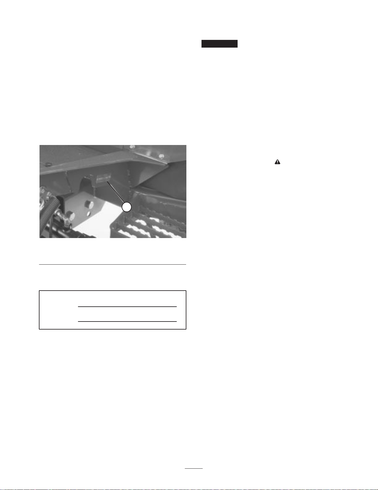
serial numbers of your product ready. Figure 1 illustrates
the location of the model and serial numbers on the
product.
This manual uses two other words to highlight information.
Important calls attention to special mechanical
information and Note: emphasizes general information
worthy of special attention.
Safety
This machine meets or exceeds CEN standard EN
836:1997 (when appropriate decals applied), and ANSI
B71.4-1990 specifications in effect at the time of
production when rear tires are filled with calcium
chloride and two rear wheel weight kits (Part No.
11–0440) are installed.
Improper use or maintenance by the operator or owner
can result in injury. To reduce the potential for injury,
comply with these safety instructions and always pay
attention to the safety alert symbol, which means
CAUTION, WARNING, or DANGER—“personal
safety instruction.” Failure to comply with the
instruction may result in personal injury or death.
1
Figure 1
1. Location of the model and serial numbers
Write the product model and serial numbers in the space
below:
Model No.
Serial No.
This manual identifies potential hazards and has special
safety messages that help you and others avoid personal
injury and even death. Danger, Warning, and Caution are
signal words used to identify the level of hazard. However,
regardless of the hazard, be extremely careful.
Danger signals an extreme hazard that will cause serious
injury or death if you do not follow the recommended
precautions.
Warning signals a hazard that may cause serious injury or
death if you do not follow the recommended precautions.
Caution signals a hazard that may cause minor or moderate
injury if you do not follow the recommended precautions.
Safe Operating Practices
The following instructions are from the CEN standard EN
836:1997, ISO standard 5395:1990, and ANSI B71.4-1999.
Training
• Read the operator’s manual and other training material
carefully. Be familiar with the controls, safety signs,
and the proper use of the equipment.
• Never allow children or people unfamiliar with these
instructions to use or service the mower. Local
regulations may restrict the age of the operator.
• Never mow while people, especially children, or pets
are nearby.
• Keep in mind that the operator or user is responsible for
accidents or hazards occurring to other people or their
property.
• Do not carry passengers.
• All drivers and mechanics should seek and obtain
professional and practical instruction. The owner is
responsible for training the users. Such instruction
should emphasize:
– the need for care and concentration when working
with ride-on machines;
– control of a ride-on machine sliding on a slope will
not be regained by the application of the brake. The
main reasons for loss of control are:
• insufficient wheel grip;
• being driven too fast;
3
Page 4

• inadequate braking;
• Do not use on slopes of more than
• the type of machine is unsuitable for its task;
• lack of awareness of the effect of ground
conditions, especially slopes;
• incorrect hitching and load distribution.
• The owner/user can prevent and is responsible for
accidents or injuries occurring to himself or herself,
other people, or property.
Preparation
• While mowing, always wear substantial footwear, long
trousers, hard hat, safety glasses, and ear protection.
Long hair, loose clothing, or jewelry may get tangled in
moving parts. Do not operate the equipment when
barefoot or wearing open sandals.
• Thoroughly inspect the area where the equipment is to
be used and remove all objects which may be thrown by
the machine.
• Warning—Fuel is highly flammable. Take the
following precautions:
– Store fuel in containers specifically designed for this
purpose.
– Refuel outdoors only and do not smoke while
refuelling.
– Add fuel before starting the engine. Never remove
the cap of the fuel tank or add fuel while the engine
is running or when the engine is hot.
– If fuel is spilled, do not attempt to start the engine
but move the machine away from the area of
spillage and avoid creating any source of ignition
until fuel vapors have dissipated.
–5° when mowing on side hills;
–10° when mowing uphill;
–15° when mowing downhill.
• Remember there is no such thing as a safe slope. Travel
on grass slopes requires particular care. To guard
against overturning:
– do not stop or start suddenly when going up or
downhill;
– engage clutch slowly, always keep machine in gear,
especially when travelling downhill;
– machine speeds should be kept low on slopes and
during tight turns;
– stay alert for humps and hollows and other hidden
hazards;
– never mow across the face of the slope, unless the
mower is designed for this purpose.
• Stay alert for holes in the terrain and other hidden
hazards.
• Use care when pulling loads or using heavy equipment.
– Use only approved drawbar hitch points.
– Limit loads to those you can safely control.
– Do not turn sharply. Use care when reversing.
– Use counterweight(s) or wheel weights when
suggested in the operator’s manual.
• Watch out for traffic when crossing or near roadways.
• Stop the blades rotating before crossing surfaces other
than grass.
– Replace all fuel tanks and container caps securely.
• Replace faulty silencers/mufflers.
• Evaluate the terrain to determine what accessories and
attachments are needed to properly and safely perform
the job. Only use accessories and attachments approved
by the manufacturer.
• Check that operator’s presence controls, safety switches
and shields are attached and functioning properly. Do
not operate unless they are functioning properly.
Operation
• Do not operate the engine in a confined space where
dangerous carbon monoxide fumes can collect.
• Mow only in daylight or in good artificial light.
• Before attempting to start the engine, disengage all
blade attachment clutches, shift into neutral, and engage
the parking brake.
• When using any attachments, never direct discharge of
material toward bystanders nor allow anyone near the
machine while in operation.
• Never operate the machine with damaged guards,
shields, or without safety protective devices in place. Be
sure all interlocks are attached, adjusted properly, and
functioning properly.
• Do not change the engine governor settings or
overspeed the engine. Operating the engine at excessive
speed may increase the hazard of personal injury.
• Before leaving the operator’s position:
– stop on level ground;
– disengage the power take-off and lower the
attachments;
– change into neutral and set the parking brake;
– stop the engine and remove the key.
4
Page 5

• Disengage drive to attachments when transporting or
not in use.
• Stop the engine and disengage drive to attachment
– before refuelling;
– before removing the grass catcher/catchers;
– before making height adjustment unless adjustment
can be made from the operator’s position.
– before clearing blockages;
• Be careful during adjustment of the machine to prevent
entrapment of the fingers between moving blades and
fixed parts of the machine.
• On multi-cylinder/multi-reel machines, take care as
rotating one cylinder/reel can cause other
cylinders/reels to rotate.
• Disengage drives, lower the cutting units, set parking
brake, stop engine and remove key and disconnect spark
plug wire. Wait for all movement to stop before
adjusting, cleaning or repairing.
– before checking, cleaning or working on the mower;
– after striking a foreign object or if an abnormal
vibration occurs. Inspect the mower for damage and
make repairs before restarting and operating the
equipment.
• Reduce the throttle setting during engine run-out and, if
the engine is provided with a shut-off valve, turn the
fuel off at the conclusion of mowing.
• Keep hands and feet away from the cutting units.
• Look behind and down before backing up to be sure of
a clear path.
• Slow down and use caution when making turns and
crossing roads and sidewalks. Stop cylinders/reels if not
mowing.
• Do not operate the mower under the influence of
alcohol or drugs
• Use care when loading or unloading the machine into a
trailer or truck
• Use care when approaching blind corners, shrubs, trees,
or other objects that may obscure vision.
• Clean grass and debris from cutting units, drives,
silencers/mufflers, and engine to help prevent fires.
Clean up oil or fuel spillage.
• Use jack stands to support components when required.
• Carefully release pressure from components with stored
energy.
• Disconnect battery and remove spark plug wire before
making any repairs. Disconnect the negative terminal
first and the positive last. Reconnect positive first and
negative last.
• Use care when checking the cylinders/reels. Wear
gloves and use caution when servicing them.
• Keep hands and feet away from moving parts. If
possible, do not make adjustments with the engine
running.
• Charge batteries in an open well ventilated area, away
from spark and flames. Unplug charger before
connecting or disconnecting from battery. Wear
protective clothing and use insulated tools.
Toro Riding Mower Safety
Maintenance and Storage
• Keep all nuts, bolts and screws tight to be sure the
equipment is in safe working condition.
• Never store the equipment with fuel in the tank inside a
building where fumes may reach an open flame or
spark.
• Allow the engine to cool before storing in any
enclosure.
• To reduce the fire hazard, keep the engine,
silencer/muffler, battery compartment and fuel storage
area free of grass, leaves, or excessive grease.
• Check the grass catcher frequently for wear or
deterioration.
• Keep all parts in good working condition and all
hardware and hydraulic fittings tightened. Replace all
worn or damaged parts and decals.
• If the fuel tank has to be drained, do this outdoors.
The following list contains safety information specific to
Toro products or other safety information that you must
know that is not included in the ANSI standard.
This product is capable of amputating hands and feet and
throwing objects. Always follow all safety instructions to
avoid serious injury or death.
Use of this product for purposes other than its intended use
could prove dangerous to user and bystanders.
Warning
Engine exhaust contains carbon monoxide, which
is an odorless, deadly poison that can kill you.
Do not run engine indoors or in an enclosed area.
• Know how to stop the engine quickly.
• Do not operate the machine while wearing tennis shoes
or sneakers.
5
Page 6

• Wearing safety shoes and long pants is advisable and
required by some local ordinances and insurance
regulations.
sufficient force to penetrate the skin and cause serious
injury. Seek immediate medical attention if fluid is
injected into skin.
• Handle fuel carefully. Wipe up any spills.
• Check the safety interlock switches daily for proper
operation. If a switch should fail, replace the switch
before operating the machine. After every two years,
replace all four interlock switches in the safety system,
whether they are working properly or not.
• Before starting the engine, sit on the seat.
• Using the machine demands attention. To prevent loss
of control:
– Do not drive close to sand traps, ditches, creeks, or
other hazards.
– Reduce speed when making sharp turns. Avoid
sudden stops and starts.
– When near or crossing roads, always yield the
right-of-way.
– Apply the service brakes when going downhill to
keep forward speed slow and to maintain control of
the machine.
• The grass baskets must be in place during operation of
the cylinders/reels or thatchers for maximum safety.
Shut the engine off before emptying the baskets.
• Raise the cutting units when driving from one work
area to another.
• Before disconnecting or performing any work on the
hydraulic system, all pressure in the system must be
relieved by stopping the engine and lowering the cutting
units and attachments to the ground.
• Check all fuel lines for tightness and wear on a regular
basis. Tighten or repair them as needed.
• If the engine must be running to perform a maintenance
adjustment, keep hands, feet, clothing, and any parts of
the body away from the cutting units, attachments, and
any moving parts, especially the screen at the side of the
engine. Keep everyone away.
• To ensure safety and accuracy, have an Authorized Toro
Distributor check the maximum engine speed with a
tachometer. Maximum governed engine speed should be
2900 RPM.
• The optional TORO tow bar (Part No. 58–7020) is for
emergency towing only. Use only the special tow bar if
it becomes necessary to tow machine. Use trailer for
normal transport. Refer to page 21 for towing
procedure.
• If major repairs are ever needed or if assistance is
desired, contact an Authorized Toro Distributor.
• Use only Toro-approved attachments and replacement
parts. The warranty may be voided if used with
unapproved attachments.
• Do not touch the engine, silencer/muffler, or exhaust
pipe while the engine is running or soon after it has
stopped because these areas could be hot enough to
cause burns.
• Stay clear of the rotating screen at the side of the engine
to prevent direct contact with your body or clothing.
• If the engine stalls or loses headway and cannot make it
to the top of a slope, do not turn the machine around.
Always back slowly, straight down the slope.
• When a person or pet appears unexpectedly in or near
the mowing area, stop mowing. Careless operation,
combined with terrain angles, ricochets, or improperly
positioned guards can lead to thrown object injuries. Do
not resume mowing until the area is cleared.
Maintenance and Storage
• Make sure all hydraulic line connectors are tight and all
hydraulic hoses and lines are in good condition before
applying pressure to the system.
• Keep your body and hands away from pin hole leaks or
nozzles that eject hydraulic fluid under high pressure.
Use paper or cardboard, not your hands, to search for
leaks. Hydraulic fluid escaping under pressure can have
Sound Pressure Level
This unit has an equivalent continuous A–weighted sound
pressure level at the operator ear of 88 dBA, based on
measurements of identical machines per Directive
98/37/EC and amendments.
Sound Power Level
This unit has a guaranteed sound power level of
105 dBA/1 pW, based on measurements of identical
machines per Directive 2000/14/EC and amendments.
Vibration Level
Hand-Arm
This unit does not exceed a vibration level of 2.5 m/s2 at
the hands based on measurements of identical machines per
ISO 5349 procedures.
Whole Body
This unit does not exceed a vibration level of 0.5 m/s2 at
the posterior based on measurements of identical machines
per ISO 2631 procedures.
6
Page 7
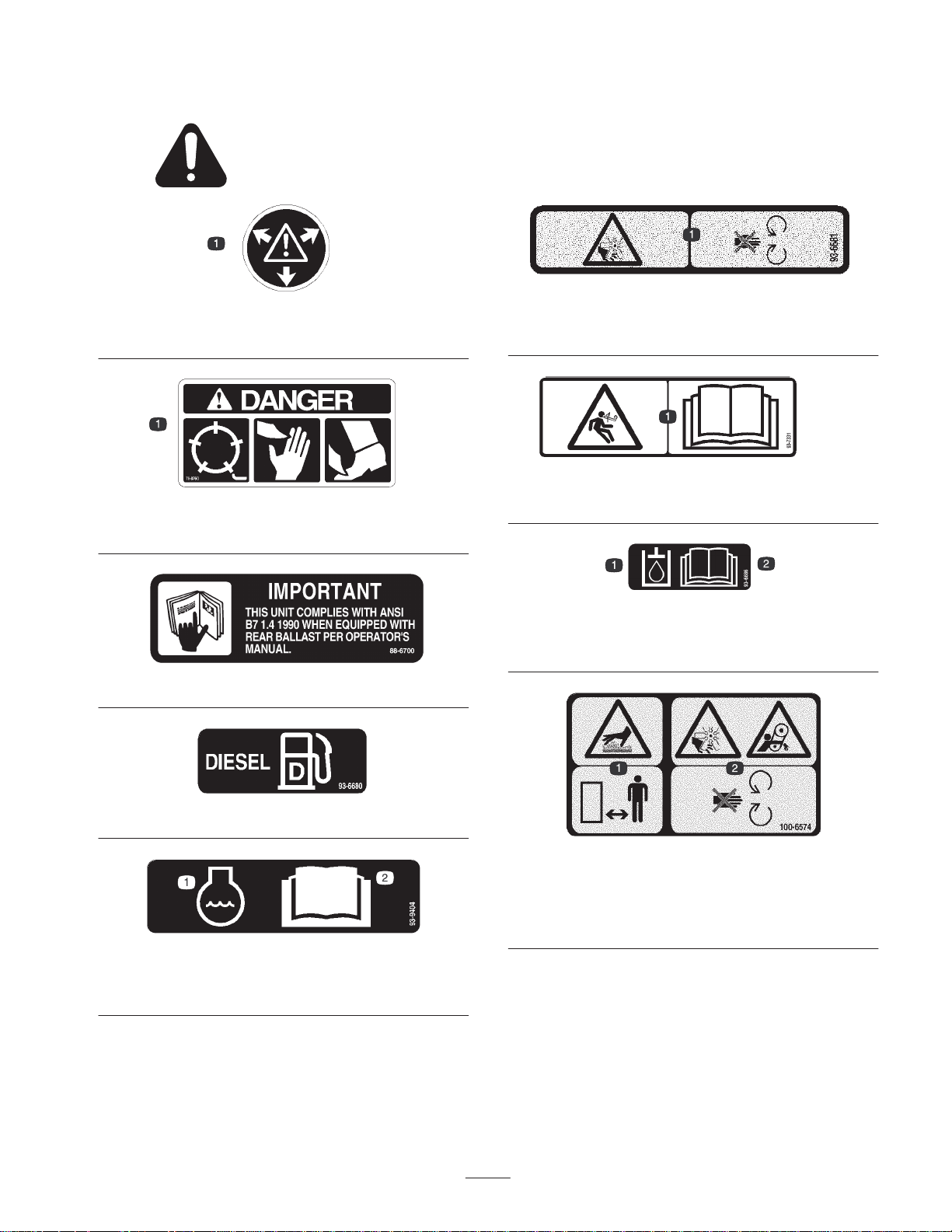
Safety and Instruction Decals
Safety decals and instructions are easily visible to the operator and are located near any area
of potential danger. Replace any decal that is damaged or lost.
59-8440
1. Warning—contents under pressure.
76-8760
1. Danger—reels can cut hands of feet.
93-6681
1. Cutting/dismemberment hazard, fan—stay away from moving
parts.
93-7331
1. Stored energy hazard—read the
Operator’s Manual.
88-6700
93-6680
93-9404
1. Engine coolant 2. Read the
Manual.
Operator’s
93-6686
1. Hydraulic oil 2. Read the
Manual.
Operator’s
100-6574
1. Hot surface/burn hazard—stay a safe distance from the hot
surface.
2. Cutting/dismemberment hazard, fan and entanglement hazard,
belt—stay away from moving parts
7
Page 8
1. Warning—read the
93-9400
Operator’s Manual
; do not tow the machine.
93-9406
1. Hydraulic oil level 2. Read the
Manual.
93-9407
1. Read the
Manual.
2. Lower the reels.
Operator’s
3. Neutral
4. Raise the reels.
Operator’s
93-9402
1. Reel—mowing speeds,
slow to fast.
2. Fast
3. Continuous variable
setting
4. Fast
5. Reel—mowing
6. Disengage
7. Reel—backlapping
8. Pull and move the lever.
9. Set the parking brake, set
the controls to neutral,
and start the engine.
93-9405
1. Tire pressure—read the
13 psi (0.9 bar) and the rear tires to 15 psi (1.0 bar).
Operator’s Manual
; fill the front tires to
93-9425
1. Warning—read the
2. High pressure fluid hazard, injection into the body—stay away
from moving parts and receive medical attention.
Operator’s Manual.
93-9399
1. Horn—press the button.
2. Warning—wear hearing
protection.
3. Read the
Manual.
4. Failure/malfunction—
press the button.
Operator’s
8
Page 9
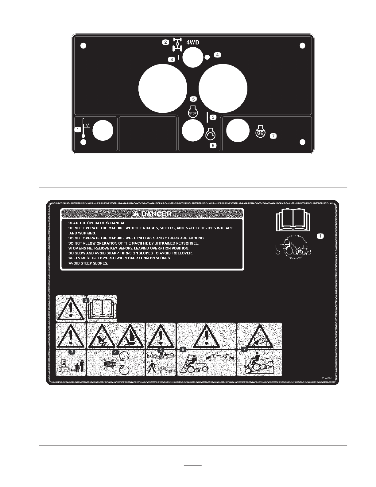
1. Temperature level
2. Four wheel drive flow divider
3. On
4. Off
98-3830
5. Engine—stop
6. Engine—start
7. Engine—preheat
1. Read the
Manual—
machine.
2. Warning—read the
Operator’s Manual.
Operator’s
do not tow the
104-5203
3. Warning—keep bystanders
a safe distance from the
machine.
4. Cutting hazard of hand or
foot—stay away from
moving parts.
5. Warning—lock the parking
brake, stop the engine, and
remove the ignition key
before leaving the machine.
6. Warning—use a rollover
protection system and wear
the seat belt.
9
7. Tipping hazard—lower the
cutting unit when driving
down slopes.
Page 10
104-5204 for CE
1. Read the
Manual—
machine.
2. Warning—read the
Operator’s Manual.
Operator’s
do not tow the
3. Warning—keep bystanders
a safe distance from the
machine.
4. Cutting hazard of hand or
foot—stay away from
moving parts.
5. Warning—lock the parking
brake, stop the engine, and
remove the ignition key
before leaving the machine.
6. Warning—use a rollover
protection system and wear
the seat belt.
7. Tipping hazard—lower the
cutting unit when driving
down slopes. Do not drive
the machine across or down
a slope greater than 15
degrees.
93-9397
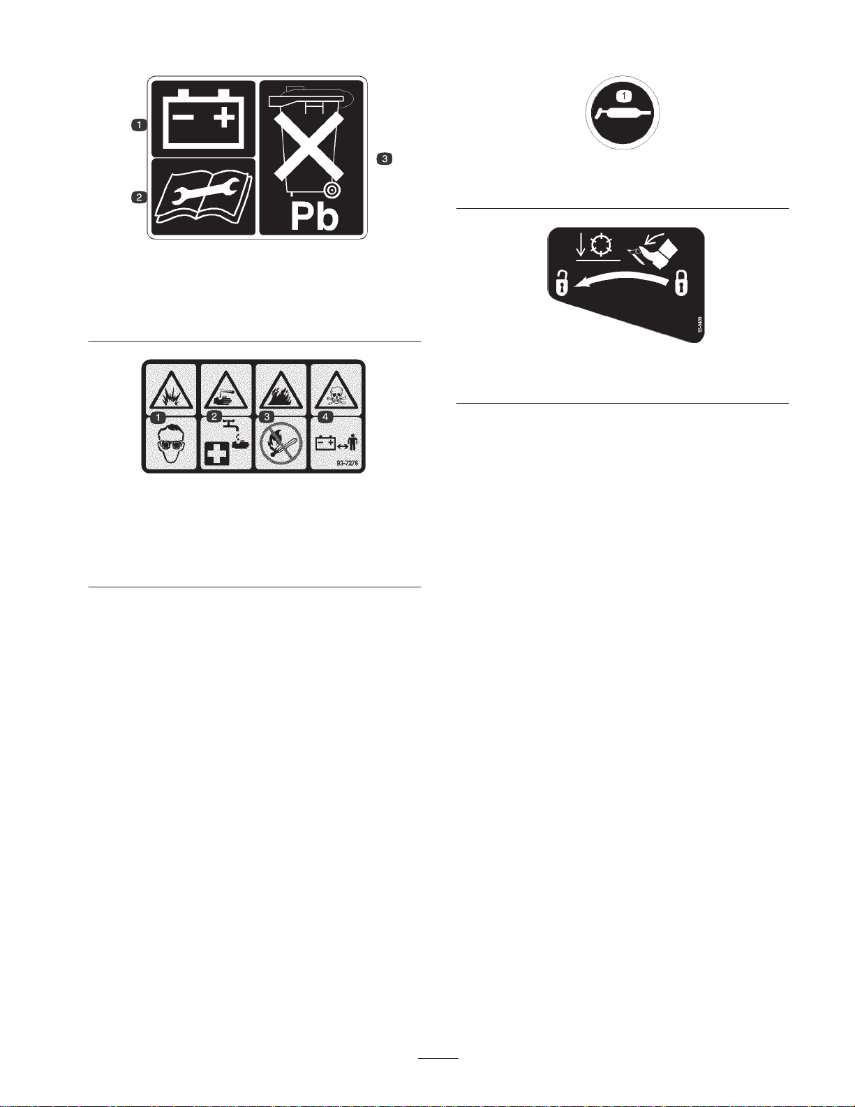
1. 7-blade reel 2. Height of cut 3. Reel—mowing speeds 4. Reel—transport speeds
10
Page 11
1. Battery
2. Read the instructions
before servicing or
performing maintenance.
1. Explosion hazard—wear
eye protection.
2. Caustic liquid/chemical
burn hazard—to perform
first aid, flush with water.
58-6520
1. Grease
93-6668
3. Contains lead; do not
discard.
93-9409
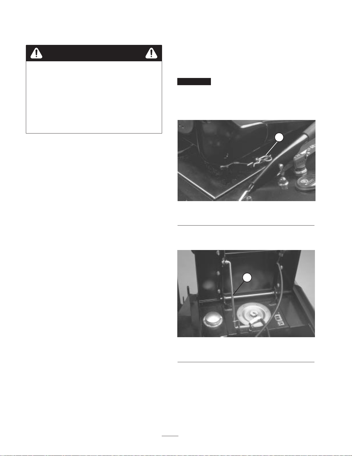
1. To unlock the reels before lowering them, press the pedal.
93-7276
3. Fire hazard—no fire, open
flames, or smoking.
4. Poison hazard—keep
children a safe distance
from the battery.
11
Page 12

Specifications
Note: Specifications and design subject to change without notice.
General Specifications
Kubota, four–cycle, four cylinder, 134 cu–in. displacement, water cooled diesel
Engine
Cooling System Capacity is 3.7 gal. (14 L) of 50/50 mixture of ethylene glycol anti–freeze.
Fuel System Capacity is 15 gal. (56.8 L) of #2 diesel fuel.
engine. Rated 40 hp @ 2300 rpm, 23:1 compression ratio. Low idle – 1200 rpm,
high idle – 2500 rpm. Injection Timing – 17–18 BTDC. Oil capacity is 8 qt. (7.6 L)
with filter.
Hydraulic System
Traction System Ground speed is 0–12.5 mph (0–20 km/h).
Cutting Unit Drive System
Seat
Diagnostic System
Steering System Automotive type, full power.
Brakes
Electrical System 12 volt, 66 amp hour (DIN) battery and 40 amp alternator. Negative ground.
Interlock System
Warning Systems
Reservoir capacity is 9.3 gal. (35.2 L) and total system capacity is 18.2 gal. (69 L).
Replaceable breather element. Replaceable spin–on filter element.
Adjustable reel speed to match clip to ground speed. Backlap reel speed is 385
rpm.
Adjusts 6 in. (15.2 cm) forward and backward. Adjustable backrest and
three–positions for operator weight. Integral seat switch at rear of bottom seat
cushion.
Test ports for traction system, cutting unit drive system, lift/counterbalance,
lift/relief, steering circuits and charge pressure are located near individual
components.
Hand brake automatically locks traction linkage in neutral. With traction motor
wheel locks engaged, twin disc brakes provide positive, emergency braking.
Designed to stop engine if operator gets off seat while cutting unit drive lever is
either in forward or reverse. Prevents engine from starting unless parking brake is
engaged, traction pedal is in neutral and cutting units are disengaged. Low
hydraulic oil level and high engine temperature protection systems stop engine
from running.
Water in fuel, hydraulic oil filter, engine coolant temperature, engine oil pressure,
voltage indicator, air cleaner clogged, hydraulic oil temperature and hydraulic oil
level.
Ground Clearance Approx. 7 in. (17.8 cm)
5 Blade Cutting Unit: 1 – 3 in. (25 – 76 mm)
Height of cut
Wheel Thread 53 in. (135 cm)
Wheel Base 57 in. (145 cm)
Operating Circle 60 in. (152 cm)
Reel Speed
Clip
7 Blade Cutting Unit: 3/8 – 1 3/4 in. (9.5 – 45 mm)
11 Blade Cutting Unit: 3/8 – 3/4 in. (9.5 – 19 mm)
800 – 1000 rpm
Note: 1200 rpm is attainable with a special coupler.
5 Blade Cutting Unit: .176 in. per mph (.352 in. at 2 mph – 1.32 in. at 7.5 mph)
7 Blade Cutting Unit: .126 in. per mph (.252 in. at 2 mph – .945 in. at 7.5 mph)
11 Blade Cutting Unit: .080 in. per mph (.16 in. at 2 mph – .600 in. at 7.5 mph)
12
Page 13

Measurements
Optional Equipment
Width-of-cut
5 Cutting Units 137 in. (348 cm)
4 Cutting Units 110 in. (279 cm)
3 Cutting Units 83 in. (211 cm)
1 Cutting Unit 29 1/2 in. (75 cm)
Overall Width
Cutting Units Raised 91 1/2 in. (232 cm)
Cutting Units Down 147 in. (373 cm)
Overall Length 110 in. (282 cm)
Height
w/o ROPS 55 1/2 in. (141 cm
w/ ROPS 82 in. (208 cm)
Dry Weight 4360 lbs.
(1717 kg)
5 Blade L. H. Cutting Unit Model No. 03752
(2 per machine)
5 Blade R. H. Cutting Unit Model No. 03753
(3 per machine)
7 Blade L. H. Cutting Unit Model No. 03754
(2 per machine)
7 Blade R. H. Cutting Unit Model No. 03756
(3 per machine)
11 Blade L. H. Cutting Unit Model No. 03741
(2 per machine)
11 Blade R. H. Cutting Unit, Model No. 03751
(3 per machine)
L. H. Dethatcher Kit Model No. 03730
(2 per machine)
R. H. Dethatcher Kit Model No. 03732
(3 per machine)
Cutting Unit Fixed Head Kit Model 03762
(1 per machine
Cutting Unit Floatation Kit Model No. 03760
(1 per machine)
Front Roller Kit Model No. 03742
(1 per machine)
Wiehle Roller Kit Model No. 03740
(1 per machine)
Rear Roller Scraper Kit Part No. 59–6090
(1 per cutting unit)
Front Roller Scraper Kit Part No. 62–6220
(1 per cutting unit)
Side Skid Kit Model No. 03744
(1 per machine)
Spark Arrester Muffler Kit Part No. 74–2900
(2 wheel drive only)
Spark Arrester Muffler Kit Part No. 92–6074
(4 wheel drive only)
R.O.P.S. Kit Part No. 92–9286
(Standard on 4 wheel
drive machines)
13
Page 14
Before Operating
Note: Determine the left and right sides of the machine
from the normal operating position.
5. The engine uses any high-quality detergent oil having
the American Petroleum Institute — API —”service
classification” CD, CE, CF, CF–4 or CG–4. Use the
following chart to select the proper viscosity grade for
the temperature expected.
Checking the Engine Oil
Crankcase capacity is 8 qt. (7.6 L) with filter.
1. Park machine on a level surface. Release engine cover
latches (Fig. 2).
1
Figure 2
1. Engine cover latch
2. Open engine cover.
3. Remove dipstick, wipe clean and reinstall dipstick into
tube and pull it out again: Oil level should be up to
FULL mark (Fig. 3).
above 77F (25 C)
32 to 77F (0 to 25 C)
below 32F (0 C)
Note: When using different oil, drain all old oil from
crankcase before adding new oil.
1. Oil fill cap
6. Install oil fill cap and dipstick.
7. Close engine cover and secure with the latches.
SAE 30, SAE 10W–30 or 10W–40
SAE 20, SAE 10W–30 or 10W–40
SAE 10W, SAE 10W–30 or
1
Figure 4
10W–40
1
Figure 3
1. Dipstick
4. If oil is below FULL mark, remove fill cap (Fig. 4) and
add oil until level reaches FULL mark. DO NOT
OVERFILL.
Check Cooling System
Check level of coolant at the beginning of each day.
Capacity of system is 3.7 gal. (14 L).
1. Carefully remove radiator cap (Fig. 6) and expansion
tank cap (Fig. 5).
Caution
If the engine has been running, pressurized hot
coolant can escape and cause burns if the radiator
cap is removed.
Allow the engine to cool at least 15 minutes or until
the radiator cap is cool enough to touch without
burning hands.
14
Page 15

2. Check level of coolant in radiator. Radiator should be
filled to the top of the filler neck and the expansion tank
filled to the marks on its side
Danger
Under certain conditions, diesel fuel and fuel
vapors are highly flammable and explosive. A fire
or explosion from fuel can burn you and others
and can cause property damage.
1
Figure 5
1. Expansion tank
3. If coolant is low, add a 50/50 mixture of water and
ethylene glycol anti–freeze. DO NOT USE WATER
ONLY OR ALCOHOL / METHANOL BASE
COOLANTS.
4. Install radiator cap and expansion tank cap.
Fill Fuel Tank
1. Remove fuel tank cap (Fig. 6).
2. Fill tank to about one inch (25 mm) below bottom of
filler neck with No. 2 diesel fuel. Then install cap.
1
• Use a funnel and fill the fuel tank outdoors, in
an open area, when the engine is off and is cold.
Wipe up any fuel that spills.
• Do not fill the fuel tank completely full. Add fuel
to the fuel tank until the level is 1 in. (25 mm)
below the bottom of the filler neck. This empty
space in the tank allows the fuel to expand.
• Never smoke when handling fuel, and stay away
from an open flame or where fuel fumes may be
ignited by a spark.
• Store fuel in a clean, safety-approved container
and keep the cap in place.
Checking the Hydraulic Fluid
The machines hydraulic system is filled at the factory with
approximately 18.2 gallons of high quality hydraulic fluid.
Check the level of hydraulic fluid before the engine is
first started and daily thereafter. Appropriate hydraulic
oils are listed below.
The following list is not assumed to be all–inclusive.
Hydraulic fluids produced by other manufacturers may be
used if they cross find a cross reference equivalent to the
products listed. Toro will not assume responsibility for
damage caused by improper substitutions, so use only
products from reputable manufacturers who will stand
behind their recommendation.
2
Figure 6
1. Radiator cap 2. Fuel tank cap
Multigrade Hydraulic Fluid – ISO VG 68
Mobil DTE 26
Amoco Rykon AW No. 68
Chevron Hydraulic Oil AW ISO 68
Conoco Hydroclear AW 68
Exxon Nutto H 68
Pennzoil AW Hydraulic Oil 68
Shell Tellus 68
Texaco Rando HD 68
Note: Many hydraulic fluids are almost colorless, making it
difficult to spot leaks. A red dye additive for the hydraulic
system oil is available in 2/3 oz. (20 ml) bottles. One bottle
is sufficient for 4–6 gal (15–22 1) of hydraulic oil. Order
part no. 44–2500 from your authorized Toro distributor.
1. Park machine on a level surface.
15
Page 16

2. Look into sight glass (Fig. 7). Oil level should be even
with arrows when checking warm oil. Oil will be 1/4 to
1/2 inch below arrows when cold.
3. If oil level is low, add hydraulic oil to the reservoir.
1
Figure 7
1. Sight glass arrows
Check Reel To Bedknife
Contact
Check Tire Pressure
For normal mowing conditions and a wide variety of turf
grasses, use these tire pressures: 13 psi front and 15 psi
rear. However, when turf is either wetter or drier than
normal, tire pressure may need to be changed. On hard
turf, use high tire pressure (18 psi front and rear). When
turf is soft, use low pressure (9 psi front and 12 psi rear).
Important Maintain even pressure in two front tires (ie.
13 psi) and both rear tires (ie 15 psi) to assure excellent
quality–of–cut. Do not exceed 10 mph transport speed (for
extended periods) when tire pressure is 12 psi or less
because tires may be damaged. Maximum transport speed
can be used when front tire pressure is 13 psi or more.
Rear Ballast
This unit complies with the ANSI B71.4–1990 Standard
when rear tires are filled with calcium chloride and a rear
wheel weight kit (Part No. 11–0440) is installed.
Important If a puncture occurs in a tire with calcium
chloride, remove unit from turf area as quickly as possible.
To prevent possible damage to turf, immediately soak
affected area with water.
Each day before operating, check reel to bedknife contact,
regardless if quality of cut had previously been acceptable.
There must be light contact across the full length of the reel
and bedknife (refer to Adjusting Cutting Units in Cutting
Unit Manual, Step #1 – Reel to Bedknife Adjustment).
16
Page 17

Operation
Note: Determine the left and right sides of the machine
from the normal operating position.
Controls
Seat Adjusting Lever
The seat adjusting lever (Fig. 8) allows 5.9 inch (15 cm)
fore and aft adjustment in 19/32 inch (15 mm) increments.
1
Figure 8
1. Seat adjusting lever
Arm Rest
3
Figure 9
1. Arm rest
2. Backrest knob
1
2
3. Suspension lever
Caution
To assure interlock switch operates properly,
seat suspension must be set for the weight of
each operator. If suspension is not set
correctly, the engine will run intermittently
and tend to stall. to correct this, set
suspension lighter.
Pivot the arm rest (Fig. 9) up and down for operator
comfort.
Backrest Knob
The backrest knob (Fig. 9) adjusts backrest angle from
5–20 degrees.
Suspension Lever
The suspension lever (Fig. 9) adjusts seat to the operator’s
weight. Use up position for light weight operators, center
position for medium weight operators and down for heavier
weight operators.
Note: Backrest and bottom seat cushions are removable.
Warning Light Test Button
Before operating machine, press warning light test button
(Fig. 10). All lights on the steering tower should illuminate.
Any light that does not come on indicates an electrical
malfunction that should be repaired immediately. Oil
pressure and electrical no charge indicator lights illuminate
when turning key switch ”ON”.
Hydraulic and Engine Indicator Lights
If these lights come on (Fig. 10), stop machine and make
repairs immediately.
17
Page 18

Engine Oil Pressure Warning
Hydraulic Oil Filter Warning
Dangerously low engine oil pressure is indicated by both a
warning indicator light and audible signal (Fig. 10). When
this occurs, stop the engine immediately and correct
problem.
7 6
2
4
3
9
1
5
8
10
Figure 10
1. Warning light check
switch
2. Engine oil pressure
warning light
3. Fuel system warning
4. Coolant temperature
warning
5. Electrical no charge
warning
6. Hydraulic oil temperature
warning
7. Hydraulic oil level warning
8. Hydraulic oil filter warning
9. Air cleaner warning
10. Alarm silence warning
A warning indicator light and audible signal (Fig. 10) warn
of clogged hydraulic filter.
Air Cleaner Warning
A warning indicator light and audible signal (Fig. 10) warn
the filter is clogged and in need of service.
Alarm Silence Button
Pressing button (Fig. 10) silences alarm. Alarm system will
disengage and automatically reset when problem is
corrected or the alarm silence button is pressed.
Traction Pedal
The traction pedal (Fig. 11) controls forward and reverse
operation. Depress top of pedal to move forward and
bottom to move backward. Ground speed depends on how
far pedal is depressed. For maximum ground speed, fully
depress pedal while throttle is in FAST. For maximum
power under load or when going uphill, keep engine rpm
high by having throttle in FAST and traction pedal held
stationary against ground speed limiter. If engine rpm
begins to decrease due to load, gradually reduce traction
pedal pressure until engine speed is increased.
To stop, reduce foot pressure on traction pedal and allow it
to return to center position. On extreme downhill slopes,
apply pressure to REVERSE side of pedal, or operate with
heel on REVERSE and toe on FORWARD portion of pedal.
Fuel System Warning
A warning indicator light and audible signal (Fig. 10) warn
of excess water in fuel system. Remove water from system.
Coolant Temperature Warning
If engine coolant temperature exceeds 221 F (105 C)
a warning indicator light (Fig. 10) illuminates and audible
signal sounds. The engine shuts down if temperature of
coolant exceeds 230 F (110 C). Switch resets
automatically when system and engine cools down.
Electrical No Charge Warning
No charge to the batteries is indicated by a warning
indicator light and audible signal (Fig. 10).
Hydraulic Oil Temperature Warning
A warning indicator light and audible signal warn (Fig. 10)
of excessively high hydraulic temperature.
Hydraulic Oil Level Warning
A warning indicator light and audible signal (Fig. 10) warn
of low hydraulic oil level. If oil level drops further, the
engine will automatically be stopped. Engine cannot be
restarted until oil supply is brought to a safe level.
3
1
4
2
Figure 11
1. Traction pedal
2. Speed limiter
3. Cam lever nut
4. Transport latch
Ground Speed Limiter
The ground speed limiter (Fig. 11) controls traction pedal
movement. Limiter lever helps control the rate of clip and
eliminates sudden speed variations over rough terrain.
18
Page 19

Important Cam lever nut (Fig. 11, Inset) can be
tightened if limiter stop will not hold traction pedal in
desired position.
Transport Latches
Latches secure cutting units in upright position for transport
operation. Latch for front cutting units is foot–operated
(Fig. 11). Hand–operated latches control the center and
outside cutting units (Fig. 12).
1
2
Hour Meter
Hour meter (Fig. 13) indicates total hours that machine has
been operated.
Note: Lines circling in the small window at left side of
gauge indicate hour meter is operating.
Engine Preheat Indicator Light
Light (Fig. 13) turns on when key is moved to ON position.
Glow plugs engage for 10 seconds, then, light goes off
when engine is ready to start.
Key Switch
Three positions: OFF, ON and START. Rotate key
(Fig. 13) to START and release key when engine begins
running. To stop engine, rotate key to OFF.
Parking Brake Lever
Pull lever (Fig. 13) up to lock brake. To release brake, pull
up on lever, press button and lower lever. Brake must be
engaged to start engine. Always engage parking brake
before getting off seat.
Mow–Backlap Lever
Figure 12
1. Center cutting unit latch 2. Outside cutting unit latch
Cutting Unit Lift Controls
The two outside levers (Fig. 13) raise and lower the two
outside cutting units. The center lever raises and lowers the
two front and the center cutting units. Engine must be
running to lower cutting units. When cutting units are
lifted, reels automatically stop. Do not allow levers to
snap–back to neutral, or cutting units may not float freely.
Engine Override Button
When button (Fig. 13) is depressed, engine can be operated
after it has over heated and automatically been stopped by
the electrical safety system. Use only for short intervals.
Fuel Level Gauge
Gauge (Fig. 13) indicates amount of fuel in tank.
Move lever (Fig. 13) forward to engage cutting units. Move
lever to the center to stop the cutting units. To backlap
cutting units, lift lever over stop and hold in the rear
position.
Important Do not move lever directly between MOW
and BACKLAP positions. Pause briefly in STOP position.
Reel Speed Control
Rotate knob (Fig. 13) clockwise to increase reel speed,
counter–clockwise to decrease speed. Use in conjunction
with the ground speed limiter to achieve appropriate rate of
clip.
Throttle Control
Move control (Fig. 13) forward to increase engine speed,
backward to decrease speed.
4 Wheel Drive Switch
Move switch (Fig. 13) forward to engage 4 wheel drive.
Move switch to rear position to disengage 4 wheel drive.
(4 wheel drive model only)
19
Page 20

1
2
3
10
1. Cutting unit lift controls
2. Mow/backlap lever
3. Throttle
9
4. Engine override button
5. Fuel gauge
6. Hour meter
4
8
Figure 13
5
7. Engine preheat indicator
light
8. Key switch
9. Hand brake
11
6
7
10. Reel speed control
11. 4 Wheel drive switch
(4 wheel drive only)
20
Page 21

Starting And Stopping
1. Sit on the seat, keep foot off traction pedal. Assure
parking brake is engaged (Fig. 13). Traction pedal and
mow/backlap lever must be in neutral.
2. Turn key switch to ON position. When glow plug
indicator light goes off, engine is ready to START.
3. Turn key to START. Release key when engine starts.
4. To stop, disengage and move all controls to neutral and
set parking brake. Raise and latch all cutting units in
transport position. Turn key to OFF and remove it from
switch.
Bleeding Fuel System
1. Park the machine on a level surface. Make sure fuel
tank is at least half full.
2. Raise engine cover.
3. Open vent plug on the fuel filter/water separator
(Fig. 14).
1
Figure 15
1. Fuel injection pump bleed
screw
6. Turn key in ignition switch to the ON position. Electric
fuel pump will begin operation, thereby forcing air out
around air bleed screw. Leave key in ON position until
a solid stream of fuel flows out around screw. Tighten
screw and turn key to OFF.
Note: Normally, engine should start after above bleeding
procedures are followed. However, if engine does not start,
air may be trapped between injection pump and injectors;
refer to Bleeding Air From Injectors.
2
1
Figure 14
1. Fuel filter/water separator 2. Vent plug
4. Turn key in ignition switch to the ON position. Electric
fuel pump will begin operation, thereby forcing air out
around vent plug. Leave key in ON position until a
solid stream of fuel flows out around plug. Tighten plug
and turn key to OFF.
5. Open the air bleed screw on the fuel injection pump
(Fig. 15).
Checking Warning Indicator
Lights
Each day before operating, assure all warning lights are
working.
Note: Alarm will continue to sound until problem is
corrected or until alarm silence button is pressed. If a
second problem is encountered, the alarm will not sound
but indicator light will illuminate.
1
Figure 16
1. Warning indicator light
test button
21
Page 22
Checking Interlock System.
Caution
If safety interlock switches are disconnected or
damaged the machine could operate unexpectedly
causing personal injury.
• Do not tamper with the interlock switches.
• Check the operation of the interlock switches
daily and replace any damaged switches before
operating the machine.
• Replace switches every two years regardless of
whether they are operating properly or not.
Pushing Or Towing Traction
Unit
In an emergency, the traction unit can be pushed or towed
for a very short distance, by using the traction pump
by–pass valve.
Important Do not push or tow the traction unit faster
than 2 to 3 MPH (3 to 5 Km/Hr) because hydraulic system
may be damaged. If traction unit must be moved a
considerable distance, transport it on a truck or trailer.
1. Remove retainer clip from seat lock rod (Fig. 17).
1. In a wide open area free of debris and bystanders, lower
cutting units to the ground. Stop engine.
2. Sit on the seat and engage parking brake (Fig. 13). Turn
key and try to start engine with Mow–Backlap lever
(Fig. 13) in both the MOW and BACKLAP positions. If
engine cranks, there is a malfunction that must be
repaired immediately. If engine does not crank, the
cutting unit drive switch is operating properly.
3. Sit on the seat and disengage the parking brake. Turn
key and try to start engine with Mow–Backlap lever in
STOP. If engine cranks, there is a malfunction that must
be repaired immediately. If engine does not crank, brake
switch is operating properly.
4. Engage parking brake, start engine and lower cutting
units. Move Mow–Backlap lever to MOW. Raise off the
seat; engine should stop within a few seconds, which
indicates the interlock system is operating. Also raise
off the seat with lever in BACKLAP. Engine should
stop, indicating interlock system is operating. If engine
does not stop, there is a malfunction that must be
repaired immediately.
Note: There is a 1 – 2 second delay between rising off seat
and engine shut off.
1
Figure 17
1. Retainer clip
2. Raise seat and support it in upright position with seat
support rod (Fig. 18).
1
5. Engage parking brake, move Mow–Backlap lever to
NEUTRAL, start engine, disengage hand brake and
raise off seat. If engine stops, interlock system is
operating. If engine does not stop, there is a
malfunction that must be repaired immediately.
Figure 18
1. Seat support rod
3. Rotate by–pass valve 90 degrees (Fig. 19). Opening the
valve opens an internal passage in the traction pump,
thereby by–passing hydraulic oil. Because oil is
by–passed, traction unit can be moved without
damaging the hydraulic system.
22
Page 23

1
Figure 19
1. By–pass valve 2.
Danger
When operating the machine, always use the seat
belt and ROPS together. Do not use a seat belt
without a ROPS.
Warning System
If a warning light comes on during operation, stop the
machine immediately and correct the problem before
continuing operation. Serious damage could occur if the
machine is operated with a malfunction. For short intervals,
however, the emergency engine override button (Fig. 13)
can be used to operate the engine if it stops because of
overheating.
Important Make sure that hand brake is engaged
before opening the by–pass valve.
4. Before starting engine, close by–pass valve. Do not start
engine when valve is open.
Important Running the machine with the by–pass
valve open will cause the hydraulic system to overheat.
Danger
Vehicle will roll with front wheel motors
disengaged. Vehicle must be on level surface or
wheels must be blocked. There is no effective
braking with wheel motors disengaged.
If towing, with front wheel motors disengaged,
Optional Tow Bar Assembly, Toro part no.
58–7020, must be used.
Operating Characteristics
Familiarization
Mowing
When you are at the area to be mowed, release front, center
and outside cutting unit transport latches, lower cutting
units, engage hand brake and stop the engine.
Cutting Unit Grass Deflectors
Adjust grass deflectors to horizontal position (Fig. 20), so
clippings disperse backward; out and away from the cutting
units. This will prevent clumps of clippings, especially wet
clippings, dropping off the machine or cutting units, which
affects the visual appearance of the turf.
Note: Generally you can adjust the deflectors down slightly
in dry grass and up slightly in wet grass.
1
Before mowing grass practice operating in an open area.
Start and stop the engine. Operate in forward and reverse.
Lower and raise cutting units simultaneously and
individually. Engage and disengage reels. Operate with all
cutting units down, then with only an individual cutting
unit. When you feel familiar with the machine, practice
operating around trees and obstacles. Also drive up and
down slopes using both mowing and transport speeds.
Figure 20
1. Grass deflector
While checking speedometer, match ground speed limiter
(Fig. 21) and reel speed control knob (Fig. 22) to desired
height–of–cut: refer to Cutting Chart (Fig. 23). Use decal at
side of steering column as a guide only.
Start engine and move throttle to FAST so engine is
running at maximum speed. Disengage hand brake. To
move forward, press traction pedal forward (Fig. 21). Move
23
Page 24

Mow–Backlap lever to MOW. Reels are now spinning.
Maintain traction pedal contact with ground speed limiter
(Fig. 21) to assure consistent clip and quality–of–cut.
2
1
Figure 21
1. Ground speed limiter 2. Traction pedal
CAUTION: This product may exceed noise levels of 85
dB(A) at the operator position. Ear protectors are
recommended for prolonged exposure to reduce the
potential of permanent hearing damage.
Transport
When mowing is complete, move MOW–BACKLAP lever
to STOP. Raise cutting units by pulling back on lift control
levers. Hold levers back until cutting units are fully raised
(a squeal from the hydraulic system means cutting units are
fully raised). Lock cutting units in place with transport
latches. Be careful when driving between objects so you do
not accidentally damage the machine or cutting units.
Matching Ground Speed and Reel Speed
Vary reel speed (while maintaining constant ground speed)
to establish the best quality of cut for the area being
mowed. Reel speeds either too fast or too slow for
conditions may effect the quality of cut. Use the cutting
chart (Fig. 23) and decal on steering console as a guide for
initial adjustment of ground and reel speeds.
1
1. Reel speed control
Figure 22
24
Page 25

CUTTING CHARTS
Relate HOC and ground speed to required reel speed setting on a 1 thru 5 scale on reel speed knob.
Note: 1 = 800 RPM; 2 = 900 RPM; 3 = 1000 RPM; 4 = 1100 RPM and 5 = 1200 RPM.
* Speeds are approximate
Recommended Reel Speed Settings
5 Blade Reel 7 Blade Reel 11 Blade Reel
Ground Speed In MPH
HOC
1.25
1.5
2.5
Note: N/R = Not Recommended
Note: Positions 4 and 5 are only attainable with a special coupler (Part No. 58–1530). Contact your Toro Dealer for information.
34567
1
N/R
N/R
N/R
2
N/R N/R N/R
5
31
35
1
N/R
24
N/R
N/R
N/R N/R
N/R
3
12
N/R
1
HOC
1/2
5/8
3/4
1.25
Ground Speed In MPH
34567
25
N/R
135
N/R
135
N/R
1
N/R
1213
N/R N/R N/R
N/R N/R
N/R
N/R
N/R
2
HOC
3/8
1/2
5/8
3/4
Ground Speed In MPH
34567
135
N/R
134
N/R
N/R
12
N/R N/RN/R
Figure 23
N/R N/R
N/R
4
1
2
25
Page 26

Maintenance
Note: Determine the left and right sides of the machine from the normal operating position.
Recommended Maintenance Schedule
Maintenance Service
Interval
After first 10 hours
After first 50 hours
Every 50 hours
Every 100 hours
Every 200 hours
Every 400 hours
Maintenance Procedure
• Check the fan and alternator belt tension.
• Torque the wheel lug nuts.
• Change the engine oil and filter.
• Check the engine RPM (idle and full throttle).
• Change the hydraulic filter.
• Adjust valves
• Change the front planetary gear lube
• Lubricate all grease fittings.
• Check the air cleaner.
• Check the battery fluid level and cable connections.
• Lubricate reel control valve grease fitting
• Lubricate reel speed valve with oil
• Change the engine oil and filter.
• Drain water from hydraulic tank
• Inspect the cooling system hoses.
• Check the fan and alternator belt tension.
• Torque the wheel lug nuts.
• Inspect cutting unit reel drive belts
• Service the air cleaner.
• Replace the fuel filters.
• Check the engine RPM (idle and full throttle).
• Inspect fuel lines and connections
1
1
• Drain and clean fuel tank
• Change the hydraulic filter
• Change hydraulic tank breather
Every 800 hours
Every 1600 hours or
every 2 years,
whichever occurs first
1
Service air cleaner whenever indicator shows red
Important Refer to your engine operator’s manual for additional maintenance procedures.
• Check rear wheel toe-in.
• Pack the 2WD rear wheel bearings.
• Change the front planetary gear lube
• Adjust valves
• Replace all moving hoses.
• Replace interlock safety switches.
• Flush/replace the cooling system fluid.
• Drain/flush hydraulic tank.
26
Page 27

If you leave the key in the ignition switch, someone could accidently start the engine and
seriously injure you or other bystanders.
Remove the key from the ignition and disconnect the wire from the spark plug before you do any
maintenance. Set the wire aside so that it does not accidentally contact the spark plug.
Daily Maintenance Checklist
Duplicate this page for routine use.
For the week of:
Caution
Maintenance Check Item
Check safety interlock operation.
Check brake operation.
Check engine oil and fuel level.
Check cooling system fluid level.
Drain the water/fuel separator.
Check the air filter restriction indicator.
Check the radiator, oil cooler and screen
for debris.
Clean traction pedal lockout
Check unusual engine noises.
1
Check unusual operating noises.
Check the hydraulic system oil level.
Check the hydraulic hoses for damage.
Check for fluid leaks.
Check the tire pressure.
Check instrument operation.
Mon. Tues. Wed. Thurs. Fri. Sat. Sun.
Check Warning lamps operation
Check the reel-to-bedknife adjustment.
Check the height-of-cut adjustment.
Lubricate all grease fittings.
2
Touch up damaged paint.
1
Check the glow plug and injector nozzles, if hard starting, excess smoke, or rough running is noted.
2
Immediately after every washing, regardless of the interval listed.
27
Page 28

Lubrication
The machine has grease fittings that must be lubricated
after every 50 hours of operation with No. 2 General
Purpose Lithium Base Grease. Lubricate fitting
immediately after every washing regardless of interval
listed. The lubrication points are: lift arms (5) (Fig. 24),
rear axle (6) (Fig. 25), floating or fixed head kit pivots
(Fig. 26) and cutting unit reel and roller bearings (Fig. 27).
Also, grease fitting on reel control valve (not shown),
located under right hand console.
Figure 26
Figure 24
Figure 25
Note: Remove the plastic caps over the fittings on the
floating or fixed head kit pivots and replace after greasing
(Fig. 26).
Figure 27
28
Page 29

General Air Cleaner
Maintenance
Check air cleaner body for damage which could possibly
cause an air leak. Replace a damaged air cleaner body.
Service the air cleaner filters when ever air cleaner
indicator light illuminates and warning signal sounds or
every 400 hours (more frequently in extreme dusty or dirty
conditions). Do not over service air filter.
Be sure cover is sealing around air cleaner body.
6. Keep air hose nozzle at least 2” from filter and move
nozzle up and down while rotating the filter element.
Inspect for holes and tears by looking through the filter
toward a bright light.
2
Servicing Air Cleaner
1. Remove knobs securing rear screen to frame (Fig. 28).
Remove screen.
2
1
Figure 28
1. Rear screen 2. Knob
2. Release latches securing air cleaner cover to air cleaner
body. Separate cover from body. Clean inside of air
cleaner cover.
1
Figure 29
1. Air cleaner body 2. Air cleaner cover
7. Inspect new filter for shipping damage. Check sealing
end of filter. Do not install a damaged filter.
8. Insert new filter properly into air cleaner body. Make
sure filter is sealed properly by applying pressure to
outer rim of filter when installing. Do not press on
flexible center of filter.
9. Reinstall cover and secure latches. Make sure cover is
positioned with TOP side up.
Engine Oil And Filter
Change oil and filter after the first 50 hours of operation
and every 100 hours thereafter.
1. Remove drain plug (Fig. 30) and let oil flow into drain
pan. When oil stops, install drain plug.
3. Gently slide primary filter out of air cleaner body to
reduce the amount of dust dislodged. Avoid knocking
filter against air cleaner body. Do not remove safety
filter.
4. Inspect primary filter and discard if damaged. Do not
wash or reuse a damaged filter.
Important Never attempt to clean a safety filter
(Located inside primary filter). Replace the safety filter
with a new one after every three primary filter services.
5. Blow compressed air from inside to the outside of dry
filter element. Do not exceed 100 psi to prevent damage
to the element.
1
Figure 30
1. Drain plug
29
Page 30

2. Remove oil filter (Fig. 31). Apply a light coat of clean
oil to the new filter seal before screwing it on. DO NOT
OVER–TIGHTEN.
3. Add oil to crankcase. Refer to Check Engine Oil.
1
Figure 31
1. Oil filter
Fuel Lines and Connections
Check lines and connections every 400 hours or yearly,
whichever comes first. Inspect for deterioration, damage, or
loose connections.
Fuel Filter / Water Separator
Drain water or other contaminants from fuel filter / water
separator (Fig. 32) daily.
1. Locate fuel filter and place a clean container under it.
2. Loosen drain plug on bottom of filter canister. Tighten
plug after draining.
Fuel System
Fuel Tank
Drain and clean fuel tank every 800 hours of operation or
yearly, whichever comes first. Also, drain and clean tank if
fuel system becomes contaminated or if machine is to be
stored for an extended period. Use clean fuel to flush out
the tank.
Danger
Under certain conditions, diesel fuel and fuel
vapors are highly flammable and explosive. A fire
or explosion from fuel can burn you and others
and can cause property damage.
• Use a funnel and fill the fuel tank outdoors, in
an open area, when the engine is off and is cold.
Wipe up any fuel that spills.
• Do not fill the fuel tank completely full. Add fuel
to the fuel tank until the level is 1/4 to 1/2 in.
(6 to 13 mm) below the bottom of the filler neck.
This empty space in the tank allows the fuel to
expand.
• Never smoke when handling fuel, and stay away
from an open flame or where fuel fumes may be
ignited by a spark.
• Store fuel in a clean, safety-approved container
and keep the cap in place.
1
2
Figure 32
1. Fuel filter/water separator 2. Drain plug
Replace filter canister after every 400 hours of operation.
1. Clean area where filter canister mounts.
2. Remove filter canister and clean mounting surface.
3. Lubricate gasket on filter canister with clean oil.
4. Install filter canister by hand until gasket contacts
mounting surface, then rotate an additional 1/2 turn.
Replacing Fuel Filter
(Machines with serial numbers prior to 230000001)
Replace the fuel filter after every 400 operating hours or
yearly, whichever occurs first.
1. Clean area where filter bowl mounts.
30
Page 31

1. Fuel filter mounting head
2. Filter bowl
Figure 33
3. Filter
4. O–ring
1
3
4
2
Bleeding Air From Injectors
Note: This procedure should be used only if fuel system
has been purged of air through normal priming procedures
and engine will not start; refer to Bleeding Fuel System.
1. Loosen the pipe connection to the No. 1 nozzle and
holder assembly.
2. Remove the filter bowl and clean mounting surface.
3. Remove filter from bowl and replace with new filter.
4. Install filter bowl by hand until O-ring contacts
mounting surface.
Replacing the Fuel Pre-Filter
(Machines with serial numbers 230000201 and up)
Replace the fuel pre-filter (Fig. 34), located between fuel
the tank and fuel pump, after every 400 operating hours or
yearly, whichever occurs first.
1. Clamp both fuel lines that connect to the fuel filter so
that fuel cannot drain when the lines are removed.
2. Loosen the hose clamps at both ends of the filter and
pull the fuel lines off of the filter.
1
1
Figure 35
1. Fuel injector (4)
2. Move throttle to FAST position.
3. Turn key in key switch to START position and watch
fuel flow around connector. Engine will crank. Turn key
to OFF position when solid flow is observed.
4. Tighten pipe connector securely.
5. Repeat steps on remaining nozzles.
Engine Cooling System
Removing Debris
Remove debris from oil cooler, radiator and rear screen
daily, clean more frequently in dirty conditions.
1. Turn engine off, release front engine cover latches and
raise engine cover. Clean engine area thoroughly of all
debris.
Figure 34
1. Fuel pre-filter
3. Slide the hose clamps onto the ends of the fuel lines.
Push the fuel lines onto the fuel filter and secure them
with the hose clamps. Be sure that the arrow on the side
of the filter points toward the injection pump.
2. Remove knobs securing rear screen to frame and
remove screen (Fig. 36).
31
Page 32

• After every 800 operating hours, drain and flush the
cooling system. Add anti–freeze (refer to Check
Cooling System.
Alternator Belt
2
1
Figure 36
1. Rear screen 2. Knob
3. Lift up on oil cooler handles and pivot rearward in
mounting slot. Clean both sides of oil cooler, radiator
and rear engine area thoroughly with compressed air.
4. Pivot oil cooler back into position and install rear
screen.
5. Lower engine cover and secure latches.
2
Condition and Tension
Check condition and tension of belt (Fig. 38) after every
100 operating hours.
• Proper tension will allow 3/8 in. (10 mm) deflection
when a force of 10 lbs. is applied on the belt midway
between the pulleys.
• If deflection is not 3/8 in. (10 mm), loosen alternator
mounting bolts. Increase or decrease alternator belt
tension and tighten bolts. Check deflection of belt
again to assure tension is correct.
1
2
Figure 38
1. Alternator 2. Mounting bolt
1
3
Figure 37
1. Oil cooler
2. Radiator
3. Inline fuel filter
Maintaining Cooling System
Capacity of the system is 3.7 gal. (14 L). Always protect
cooling system with a 50/50 solution of water and ethylene
glycol anti–freeze. DO NOT USE WATER ONLY IN
COOLING SYSTEM.
• After every 100 operating hours, tighten hose
connections. Replace any deteriorated hoses.
Adjusting Hand Brake &
Traction Switches
In time, the hand brake cable may stretch, causing the
engine not to start. If this happens, adjust the cable
(Fig. 39).
1. Pull brake lever to 3rd click.
2. Pull brake lever up one additional click.
3. Adjust four U–bracket nuts equally so spring has
tension. Adjustment affects operation of traction
switches.
32
Page 33

4. Adjust four U–bracket nuts so engine will start and run
when hand brake is at fourth click, but will not start or
run when hand brake is at second click.
1
2
1
5
1. Parking brake
2. Brake cable
3. U–bracket nuts
4
3
Figure 39
4. Traction switches
5. Traction pedal
Adding Hydraulic Oil
Capacity of the hydraulic reservoir is approximately 9.3
gal. (35.2 L).
With machine on a level surface, hydraulic oil level should
be 1/4 to 1/2 inch below arrows on sight glass, when oil is
cold. Warm oil should be even with arrows on sight glass
(Fig. 40). If level is low, add hydraulic oil.
Figure 41
1. Reservoir cover
Important To prevent contamination, clean top of
hydraulic oil containers before opening. Assure pour spout
and funnel are clean.
3. Install reservoir cover, lower seat and secure with lock
pin.
Draining Water From Hydraulic
Reservoir
After every 100 operating hours, drain water from
hydraulic reservoir. Before draining, allow machine to set
about 8 hours to allow water to settle to bottom of reservoir.
1. Open drain plug (Fig. 42) one–half turn and allow fluid
to flow into drain pan until water is not noticed in
hydraulic oil.
1
Figure 40
1. Sight glass arrows
1. Remove seat lock pin, raise seat and hold open with
support rod.
2. Clean around reservoir cover (Fig. 41). Remove cover
and add hydraulic oil until it is even with arrows on
sight glass (Fig. 40). Refer to Checking the Hydraulic
Oil.
1
Figure 42
1. Drain plug
2. Tighten drain plug and add hydraulic oil, Refer to
Adding Hydraulic Oil.
33
Page 34

Changing Hydraulic Oil
Normally, change hydraulic oil after every 2 years or 1500
operating hours. If oil becomes contaminated, contact your
local TORO distributor because the system must be
flushed. Contaminated oil looks milky or black when
compared to clean oil.
1. Remove drain plug (Fig. 42) from reservoir and let
hydraulic oil flow into drain pan. Tighten plug when
hydraulic oil stops draining.
2. Fill reservoir with approximately 9.3 gallons of
hydraulic oil. Refer to Checking the Hydraulic Oil.
1
Important Use only hydraulic oils specified. Other
fluids could cause system damage.
3. Install reservoir cover, lower seat and secure with lock
pin. Start engine, run slowly and use all hydraulic
controls to distribute hydraulic oil throughout the
system. Also check for leaks. Then stop the engine.
4. With cutting units up and oil warm, look into sight glass
(Fig. 40). If hydraulic oil is not even with arrows, add
enough to raise to proper level. Do not fill full if oil is
cold.
Replacing Hydraulic Filter
Initially, change filter after the first 50 operating hours,
thereafter, every 800 operating hours, annually, or on
indication.
Use Toro replacement filter (Part No. 86–6110).
Important Use of any other filter may void the
warranty on some components.
1. Remove seat lock pin, raise seat and hold open with
support rod. Also remove panel (secured with magnets)
ahead of the seat.
Figure 43
1. Hydraulic Filter
6. Look into sight glass (Fig. 40). Hydraulic oil level
should be even with arrows when oil is warm. If level
is low, add hydraulic oil to the reservoir.
Note: Under certain conditions, a bypass valve in the filter
mounting plate allows oil to bypass the filter. Before the
filter starts to bypass a warning light on the steering
console will illuminate. The warning light may come on
momentarily when the oil is cold. If the light does not go
out after the oil is warm, the filter is clogged or an
electrical problem exists. Correct problem before
commencing operation.
Replacing Hydraulic System
Breather
Change hydraulic system breather after every 800
operating hours, or annually, whichever comes first. More
often in extremely dusty or dirty conditions.
1. Release latches and open engine cover.
2. Clean area around filter mounting area (Fig. 43). Place
drain pan under filter and remove filter.
3. Lubricate new filter gasket and fill the filter with
hydraulic oil.
4. Assure filter mounting area is clean. Screw filter on
until gasket contacts mounting plate. Then tighten filter
one–half turn.
5. Start engine and let it run slowly for about two minutes
to purge air from the system. Stop the engine and check
for leaks.
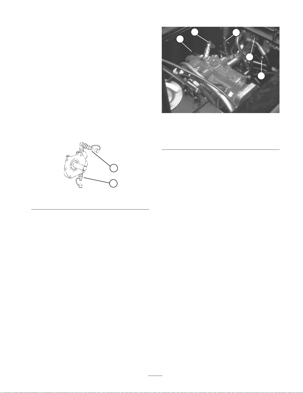
2. Clean around the breather and unscrew it with a wrench
(Fig. 44). Install new breather.
1
Figure 44
1. Breather
3. Close engine cover and latch securely.
34
Page 35
Checking Hydraulic Lines And
Hoses
Check hydraulic lines and hoses daily for leaks, kinked
lines, loose mounting supports, wear, loose fittings, weather
deterioration and chemical deterioration. Make all
necessary repairs before operating.
Hydraulic System Test Ports
The test ports (Fig. 45 & 46) are used to test the hydraulic
circuits. Check all pressures when engine is at full speed
and hydraulic oil is at normal operating temperature.
Contact your local Toro distributor for assistance.
2
5
1
4
3
1. Traction Forward and Reverse (Fig. 45) (behind wheel
motors) has a normal relief setting of approximately
5300 psi and 50 – 150 psi charge pressure. Use a gauge
with 7500 – 10,000 psi full scale rating.
1
2
Figure 45
1. Traction forward 2. Traction reverse
2. Cutting unit Counterbalance has adjustable pressure.
• Normal Setting Hot Oil: 500–550 psi
Cold Oil: 600–650 psi
• Maximum Hill Climbing Setting
Hot Oil: 550+ psi
Cold Oil: 650+ psi
• Maximum Quality of Cut Setting
Hot Oil: 500 psi
Cold Oil: 600 psi
Figure 46
1. Lift relief circuit
2. Charge pressure circuit
3. Cutting unit
counterbalance
3. Cutting Unit Circuit has a normal relief setting of
approximately 2700–3000 psi.
4. Steering Circuit has a normal relief setting of
approximately 1500 psi.
5. Lift/relief Circuit has a normal relief setting of
approximately 2650–2750 psi.
6. Charge Pressure Circuit has a normal relief setting of
approximately 100–150 psi.
4. Cutting unit circuit
5. Steering circuit
Rear Wheel Toe–in
After every 800 operating hours or annually, check rear
wheel toe–in.
1. Measure center–to–center distance (at axle height) at
front and rear of steering tires (Fig. 47). Front
measurement must be 1/8 in. less than rear
measurement.
• Lift circuit relief pressure is approximately 2650 psi
when counterbalance setting is 550 psi.
Note: Changes in counterbalance setting will effect the lift
circuit relief pressure.
35
Page 36

Figure 47
2. Loosen clamps at both ends of tie rods (Fig. 48).
3. Rotate tie rod to move front of tire inward or outward.
4. Tighten tie rod clamps when adjustment is correct.
Note: Make sure tie rod clamps are positioned so they do
not interfere with steering linkage.
2
1
1
Figure 49
1. Check/drain plug
Engine Valve Clearance
Adjust every 800 operating hours.
Figure 48
1. Clamp 2. Tie Rod
Checking Planetary Gear Drive
Initially, check oil level after 50 operating hours and check
every 800 hours thereafter. Oil capacity is approximately
30 oz. (885 ml) high quality SAE 80–90 wt. Gear Lube
(ISO 150/220).
1. To check the oil level, the oil should be at the bottom of
the check/drain plug hole (Fig. 49) when the hole is
placed in the 3 o’clock or 9 o’clock position. The
traction unit must be on level ground when making this
check.
36
Page 37

Hydraulic Schematic
3
5
1
A
B
(TYP) IN
A
B
TEST PORT
CUTTING
CIRCUIT
G
2
4
PRIORITY
OUT
3000
T
PSI
BA
2100@50
PSI
P
T
A
B
C
T
TEST PORT
LIFT CYLS
R
L
E
D
F
RIGHT SIDE
TP
T
TEST PORT
CHARGE
PRESSURE
IN
2500 HI-IDLE
1100 LO-IDLE
INLET
A
(FWD)
B
(REV)
SHUT-
DOWN
WARNING
LEFT SIDE
P1
P2
S1
(FWD)
LC1
TEST PORTS
STEERING CIRCUIT
COUNTER-BALANCE
TRACTION FORWARD
TRACTION REVERSE
37
LC2
4 WHEEL DRIVE ONLY
RH
B
A
REAR
B
A
LH
Page 38

Electrical Schematic
(+)
(–)
Y
OR
878687a
30
FUEL GAUGE
(+)
2
4 WHEEL
GY
S
I
FUEL
G
HR
(–)
PK
1
DRIVE
KIT
OPTIONAL
CRUISE CONTROL
KIT
OPTIONAL
ROAD LIGHT
SENDING UNIT
4WD
SOLENOID
4WD OPTION
BK/WBU
BUBK
RUN –––– B+I+A; X+Y
STOP –––– NONE
START ––– B+I+S
40 A FUSE
BK R/BK
BK/W
5 A FUSE
W
BU
7.5 A FUSE
BN
A
B
Y
20 A FUSE
BK/W
BK/W
T
Y
X
S
I
R
85
BK/W
BK
T
IGNITION SW.
ALARM
ALARM
OR
VIO
BK/W
VIO
OR
BN
GY
SILENCE ALARM
NO
#2
NC
C
NO
NC
C
#1
REEL DRIVE
NEUTRAL SW.
(DISENGAGED)
OVERRIDE
HIGH TEMP
OR
MFD
6500
HYD. OIL
LEVEL SW.
(OPENS WHEN LOW)
R/BK
SOLENOID
ENGINE RUN
FUEL PUMP
AIR FILTER
HOLD
AIR FILTER
OR
R/BK
HYD. OIL
R
VIO
VIO
W
PULL
TEMP.
HYD. OIL TEMP.
A
VIO
KUBOTA
GLOW PLUG
CONTROLLER
BK/W
R
BK
C
OR
87
HYD.OIL
FILTER
W
HYD. OIL LOW
HYD.OIL FILTER
T
W
Y
BK/W
GLOW INDICATOR
B
T
5
41263
GLOW RELAY
GN
85 86
87
30
ENGINE OVER TEMP.
R/BK
NC
(OPENS AT 110 C)
VIO
RUN RELAY
85 86
BK
30
R
R
ALTERNATOR
BK/W
ENGINE
(105 C)
GN
Y
ALTERNATOR
BK
SEAT SW.
(OPERATOR NOT PRESENT)
Y
BU
L
G
B
I
ENGINE
OVER TEMP .
OIL PRESSURE
GN/W
OIL PRESSURE
ENGINE OVER TEMP.
BK
NC
(BRAKE OFF)
PARKING BRAKE #1
W
VIO
R
Y/BU
C
NO
W
OR
85
86
BK
FUSIBLE LINK
B+
TEST ALARM
WATER IN FUEL
DKGN
WATER IN FUEL
T
30
87
87a
PARKING BRAKE
BN
Start
STARTER
BK
GLOW PLUGS (4)
12 VOLT
BATTERY
38
Sheet No.:43
Page 39

Battery Care
Warning
Warning
CALIFORNIA
Proposition 65 Warning
Battery posts, terminals, and related accessories
contain lead and lead compounds, chemicals
known to the State of California to cause cancer
and reproductive harm. Wash hands after
handling.
Important Before welding on a machine, disconnect
both cables from the battery, disconnect both wire harness
plugs from the electronic control unit and the terminal
connector from the alternator to prevent damage to the
electrical system.
Warning
Battery terminals or metal tools could short
against metal tractor components causing sparks.
Sparks can cause the battery gasses to explode,
resulting in personal injury.
• When removing or installing the battery, do not
allow the battery terminals to touch any metal
parts of the machine.
• Do not allow metal tools to short between the
battery terminals and metal parts of the
machine.
Incorrect battery cable routing could damage the
tractor and cables causing sparks. Sparks can
cause the battery gasses to explode, resulting in
personal injury.
• Always disconnect the negative (black) battery
cable before disconnecting the positive (red)
cable.
• Always connect the positive (red) battery cable
before connecting the negative (black) cable.
Note: Check battery condition weekly or after every 50
hours of operation. Keep terminals and entire battery case
clean because a dirty battery will discharge slowly. To clean
the battery, wash the entire case with solution of baking
soda and water. Rinse with clear water. Coat the battery
posts and cable connectors with Grafo 112X (skin-over)
grease (Toro Part No. 505-47) or petroleum jelly to prevent
corrosion.
Danger
Battery electrolyte contains sulfuric acid which is a
deadly poison and causes severe burns.
• Do not drink electrolyte and avoid contact with
skin, eyes or clothing. Wear safety glasses to
shield your eyes and rubber gloves to protect
your hands.
• Fill the battery where clean water is always
available for flushing the skin.
39
Page 40

The Toro General Commercial Products Warranty
A Two-Year Limited Warranty
Conditions and Products Covered
The Toro Company and its affiliate, Toro Warranty Company,
pursuant to an a g r eement between them, jointly warrant your 1996
or newer Toro Commercial Product (“Product”) purchased after
January 1, 1997, to be free from defects in materials or
workmanship for tw o years or 1500 operational hours*, whichever
occurs first. Where a warrantable condition exists, we will repair the
Product at no cost to you including diagnosis, labor, parts, and
transportation. This warranty begins on the date the Product is
delivered to the original retail purchaser.
* Product equipped with hour meter
Instructions for Obtaining Warranty Service
You are responsible for notifying the Commercial Products
Distributor or Authorized Commercial Products Dealer from whom
you purchased the Product as soon as you believe a warrantable
condition exists.
If you need help locating a Commercial Products Distributor or
Authorized Dealer, or if you have questions regarding your
warranty rights or responsibilities, you may contact us at:
Toro Commercial Products Service Department
Toro Warranty Company
8111 Lyndale Avenue South
Bloomington, MN 55420-1196
952-888-8801 or 800-982-2740
E-mail: commercial.service@toro.com
Owner Responsibilities
As the Product owner, you are responsible for required maintenance and adjustments stated in your operator’s manual. Failure
to perform required maintenance and adjustments can be grounds
for disallowing a warranty claim.
Items and Conditions Not Covered
Not all product failures or malfunctions that occur during the
warranty period are defects in materials or workmanship. This
express warranty does not cover the following:
• Product failures which result from the use of non-Toro
replacement parts, or from installation and use of add-on,
modified, or unapproved accessories
• Product failures which result from failure to perform required
maintenance and/or adjustments
• Product failures which result from operating the Product in an
abusive, negligent or reckless manner
• Parts subject to consumption through use unless found to be
defective. Examples of parts which are consumed, or used up,
during normal Product operation include, but are not limited to,
blades, reels, bedknives, tines, spark plugs, castor wheels,
tires, filters, belts, etc.
• Failures caused by outside influence. Items considered to be
outside influence include, but are not limited to, weather,
storage practices, contamination, use of unapproved coolants,
lubricants, additives, or chemicals, etc.
• Normal “wear and tear” items. Normal “wear and tear” includes,
but is not limited to, damage to seats due to wear or abrasion,
worn painted surfaces, scratched decals or windows, etc.
Parts
Parts scheduled for replacement as required maintenance are
warranted for the period of time up to the scheduled replacement
time for that part.
Parts replaced under this warranty become the property of Toro.
T oro will make the final decision whether to repair any existing part
or assembly or replace it. Toro may use factory remanufactured
parts rather than new parts for some warranty repairs.
General Conditions
Repair by an Authorized Toro Distributor or Dealer is your sole
remedy under this warranty.
Neither The Toro Company nor Toro Warranty Company is
liable for indirect, incidental or consequential damages in
connection with t h e use of the T oro Products covered by this
warranty, including any cost or expense of providing substitute equipment or service during reasonable periods of
malfunction or non-use pending completion of repairs under
this warranty. Except for the Emissions warranty referenced
below, if applicable, there is no other express warranty. All
implied warranties of merchantability and fitness for use are
limited to the duration of this express warranty.
Some states do not allow exclusions of incidental or consequential
damages, or limitations on how long an implied warranty lasts, so
the above exclusions and limitations may not apply to you.
This warranty gives you specific legal rights, and you may also
have other rights which vary from state to state.
Note regarding engine warranty: The Emissions Control System
on your Product may be covered by a separate warranty meeting
requirements established by the U.S. Environmental Protection
Agency (EPA) and/or the California Air Resources Board (CARB).
The hour limitations set forth above do not apply to the Emissions
Control System Warranty. Refer to the Engine Emission Control
Warranty Statement printed in your operator’s manual or contained in the engine manufacturer’s documentation for details.
Countries Other than the United States or Canada
Customers who have purchased Toro products exported from the United States or Canada should contact their Toro Distributor (Dealer)
to obtain guarantee policies for your country, province, or state. If for any reason you are dissatisfied with your Distributor’s service or
have difficulty obtaining guarantee information, contact the Toro importer. If all other remedies fail, you may contact us at Toro Warranty
Company.
Part No. 374-0031 Rev. –
 Loading...