

Page 1

FormNo.3402-461RevA
8or11-BladeDPACuttingUnit
Reelmaster
ModelNo.03698—SerialNo.316000001andUp
ModelNo.03699—SerialNo.316000001andUp
®
6000-DSeriesTractionUnit
Registeratwww.T oro.com.
OriginalInstructions(EN)
*3402-461*A
Page 2
WARNING
CALIFORNIA
Proposition65Warning
Thisproductcontainsachemicalorchemicals
knowntotheStateofCaliforniatocausecancer,
birthdefects,orreproductiveharm.
ThisproductcomplieswithallrelevantEuropeandirectives.
Fordetails,pleaseseetheDeclarationofIncorporation(DOI)
atthebackofthispublication.
ModelNo.
SerialNo.
Thismanualidentiespotentialhazardsandhassafety
messagesidentiedbythesafety-alertsymbol(Figure2),
whichsignalsahazardthatmaycauseseriousinjuryordeath
ifyoudonotfollowtherecommendedprecautions.
Figure2
1.Safety-alertsymbol
Introduction
Readthisinformationcarefullytolearnhowtooperateand
maintainyourproductproperlyandtoavoidinjuryand
productdamage.Youareresponsibleforoperatingthe
productproperlyandsafely.
YoumaycontactTorodirectlyatwww .Toro.comforproduct
safetyandoperationtrainingmaterials,accessoryinformation,
helpndingadealer,ortoregisteryourproduct.
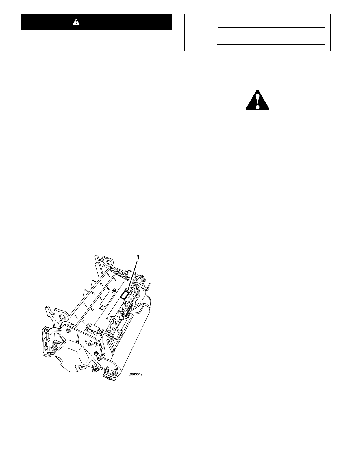
Wheneveryouneedservice,genuineT oroparts,oradditional
information,contactanAuthorizedServiceDealerorToro
CustomerServiceandhavethemodelandserialnumbersof
yourproductready.Figure1identiesthelocationofthe
modelandserialnumbersontheproduct.Writethenumbers
inthespaceprovided.
Thismanualuses2wordstohighlightinformation.
Importantcallsattentiontospecialmechanicalinformation
andNoteemphasizesgeneralinformationworthyofspecial
attention.
Contents
Safety...........................................................................3
SafetyandInstructionalDecals.................................3
Setup............................................................................4
1InspectingtheCuttingUnit....................................4
2RemovingtheTipperAssemblies............................4
3MountingtheLiftBracketsandChains.....................5
4UsingtheKickstand..............................................6
5AdjustingtheRearShield.......................................7
6MountingtheCounterweights................................7
7InstallingtheCuttingUnits.....................................8
ProductOverview.........................................................10
Specications........................................................10
Attachments/Accessories........................................10
Operation....................................................................10
MakingAdjustments...............................................10
Height-of-CutChartTerms.....................................12
Height-of-CutChart...............................................14
Maintenance.................................................................18
LubricatingtheCuttingUnit....................................18
AdjustingtheReelBearings......................................18
ServicingtheBedknife............................................19
ServicingtheBedbar...............................................20
ServicingtheRoller.................................................22
1.Locationofthemodelandserialnumbers
©2016—TheToro®Company
8111LyndaleAvenueSouth
Bloomington,MN55420
Figure1
Contactusatwww.Toro.com.
2
PrintedintheUSA
AllRightsReserved
Page 3
Safety
advisableandrequiredbysomelocalordinancesand
insuranceregulations.Securelooseclothing.
ThismachinehasbeendesignedinaccordancewithENISO
5395:2013.
Improperuseormaintenanceofthisequipmentcan
resultininjuryordeath.T oreducethepotentialfor
injuryordeath,complywiththefollowingsafety
instructions.
•Read,understand,andfollowallinstructionsinthe
tractionunitOperator’sManualbeforeoperatingthecutting
unit.
•Read,understand,andfollowallinstructionsinthis
Operator’sManualbeforeoperatingthecuttingunit.
•Neverallowchildrentooperatethetractionunitor
cuttingunits.Donotallowadultstooperatethetraction
unitorthecuttingunitswithoutproperinstruction.Only
trainedoperatorswhohavereadthisOperator’sManual
shouldoperatethecuttingunits.
•Neveroperatethecuttingunitswhentired,ill,orunder
theinuenceofdrugsoralcohol.
•Keepallshieldsandsafetydevicesinplace.Ifashield,a
safetydevice,oradecalisillegibleordamaged,repairor
replaceitbeforeresumingoperation.Also,tightenany
loosenuts,bolts,andscrewstoensurethatthecutting
unitisinsafeoperatingcondition.
•Wearappopriateclothing,includingeyeprotection;
substantial,slip-resistantfootwear;andhearing
protection.Wearingsafetyshoesandlongpantsis
•Tiebacklonghair.Donotwearjewelry.
•Removealldebrisorotherobjectsthatmightbepicked
upandthrownbythereelbladesofthecuttingunit.Keep
allbystandersawayfromtheworkingarea.
•Ifthecuttingbladesstrikeasolidobjectortheunit
vibratesabnormally,stopandshutofftheengine.Check
thecuttingunitfordamagedparts.Repairanydamage
beforestartingandoperatingthecuttingunit.
•Lowerthecuttingunitstotheground,settheparking
brake,shutofftheengine,andremovethekeyfrom
theignitionswitchwheneveryouleavethemachine
unattended.
•Besurethatthecuttingunitsareinsafeoperating
conditionbykeepingnuts,bolts,andscrewstight.
•Removethekeyfromtheswitchtopreventaccidental
startingoftheenginewhenservicing,adjusting,orstoring
themachine.
•Performonlythosemaintenanceinstructionsdescribedin
thismanual.Ifmajorrepairsareeverneededorassistance
isdesired,contactanAuthorizedT oroDistributor.
•Toensureoptimumperformanceandcontinuedsafety
certicationofthemachine,useonlygenuineToro
replacementpartsandaccessories.Replacementparts
andaccessoriesmadebyothermanufacturerscouldbe
dangerous,andsuchusecouldvoidtheproductwarranty.
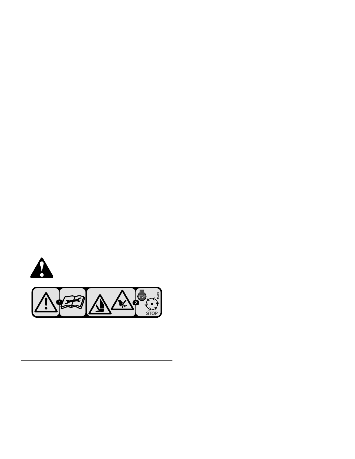
SafetyandInstructionalDecals
Safetydecalsandinstructionsareeasilyvisibletotheoperatorandarelocatednearanyareaofpotential
danger.Replaceanydecalthatisdamagedorlost.
93–6688
1.Warning—readthe
Operator’sManualbefore
performingmaintenance.
2.Cuttinghazardofhandor
foot—shutofftheengine
andwaitforallmoving
partstostop.
3
Page 4

Setup
LooseParts
Usethechartbelowtoverifythatallpartshavebeenshipped.
ProcedureDescription
1
2
3
4
5
6
7
Cuttingunit
Nopartsrequired
Liftchain5/7
Chainbracket5/7
U-bolt
Nut
Screw5/7
Washer
Nut
Kickstand(suppliedwithtractionunit)
Nopartsrequired
Nopartsrequired
LargeO-ring5/7
Screw
Qty.
1Inspectthecuttingunit.
–
5/7
10/14
5/7
5/7
1
–
–
2
Removethetipperassemblies.
Mounttheliftbracketsandchains.
Usethekickstandwhentippingthe
cuttingunit.
Adjusttherearshield.
Mountthecounterweights.
Installthecuttingunits.
Use
MediaandAdditionalParts
Description
PartsCatalog
Operator'sManual
Note:Determinetheleftandrightsidesofthemachinefromthenormaloperatingposition.
Qty.
1
1
Reviewthematerialandsaveitinanappropriateplace.
3.Makesurethatthecarrierframesuspensionoperates
freelyanddoesnotbindwhenmovedbackandforth.
1
InspectingtheCuttingUnit
2
Partsneededforthisprocedure:
1
Cuttingunit
Procedure
Removethecuttingunitfromtheboxanddothefollowing:
1.Checkeachendofthereelforgrease.
Note:Greaseshouldbevisibleinthereelbearings
andinternalsplinesofthereelshaft.
2.Ensurethatallnutsandboltsaresecurelytightened.
RemovingtheTipper Assemblies
NoPartsRequired
Procedure
Removethetipperassemblies(ifsoequipped)fromthe
number1,number2,andnumber3liftarmstoavoid
interferencewiththecarrierframesofthecuttingunits.
Use
4
Page 5

1.Removethelocknutandthewashersecuringthepivot
1
2
3
g020546
rodtothenumber2liftarm(Figure3).Removethe
pivotrodandspringfromtheliftarm.Repeatthe
procedureonthenumber1andnumber3liftarms.
Figure3
1.Pivotrod2.Tippersupportbracket
w/roller
Figure4
1.Cuttingunit16.Cuttingunit6
2.Cuttingunit27.Cuttingunit7
3.Cuttingunit3
4.Cuttingunit4
5.Cuttingunit5
8.Reelmotor
9.Weight
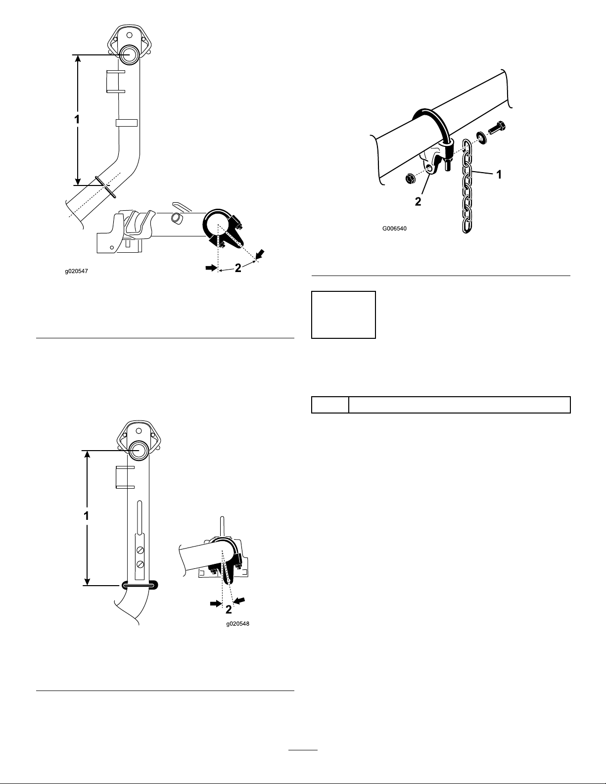
1.Onliftarmnumbers1,4,and5,positionthechain
bracketsandU-bolts38.1cm(15inches)behindthe
centerlineofthepivotknuckle(Figure5).
2.Onliftarmnumbers1and5thebracketsshouldbe
rotatedtotheright10degreesfromvertical(Figure5).
Note:Thetipperbracketwiththerollerandthetipper
supportbracketsarenotrequiredwhenoperatingthe
DPAcuttingunits(Figure3).
2.Disconnecttheliftchainsfromthecuttingunits,if
attached.
3
MountingtheLiftBracketsand Chains
Partsneededforthisprocedure:
5/7Liftchain
5/7Chainbracket
U-bolt
5/7
10/14
Nut
5/7Screw
Washer
5/7
Nut
5/7
3.Onliftarmnumber4thebracketshouldberotatedto
theleft10degreesfromvertical(Figure5).
Figure5
1.Liftarmnumber5=
38.1cm(15inches)
2.Liftarmnumber4=
10degrees
3.Liftarmnumbers1and5=
10degrees
4.Onliftarmnumbers2and3,positionthebracketsand
Procedure
MountachainbrackettoeachliftarmwithaU-boltand2
nuts.Positionthebracketsasfollows:
Note:RefertoFigure4todeterminetheliftarmnumber
U-bolts38.1cm(15inches)behindthecenterlineof
thepivotknuckle(Figure6).
Note:Rotatethebrackets45degreestotheoutboard
sideofthemachine.
beingdescribed.
5
Page 6
1
2
g020547
Figure6
1
2
g020548
7.Mountaliftchaintoeachchainbracketwithascrew,
awasher,andanut,positioningthemasshownin
Figure8.
Figure8
1.Liftchain2.Chainbracket
1.Liftarmnumber
2=38.1cm
(15inches)
5.Onliftarmnumber6andnumber7,positionthe
bracketsandU-bolts36.8cm(14.5inches)behindthe
centerlineofthepivotknuckle(Figure7).
Note:Rotatethebrackets10degreestotheoutboard
sideofthemachine.
2.Liftarmnumber3=
45degrees
4
UsingtheKickstand
Partsneededforthisprocedure:
1
Kickstand(suppliedwithtractionunit)
Procedure
Wheneverthecuttingunithastobetippedtoexposethe
bedknife/reel,propuptherearofthecuttingunitwiththe
kickstand(suppliedwiththetractionunit)tomakesurethat
thenutsonthebackendofthebedbaradjustingscrewsare
notrestingontheworksurface(Figure9).
Figure7
1.Liftarmnumber
6=36.8cm
(14.5inches)
6.TightenalltheU-boltnutsto52to65N∙m(38to48
ft-lb).
2.Liftarmnumber7=
10degrees
6
Page 7
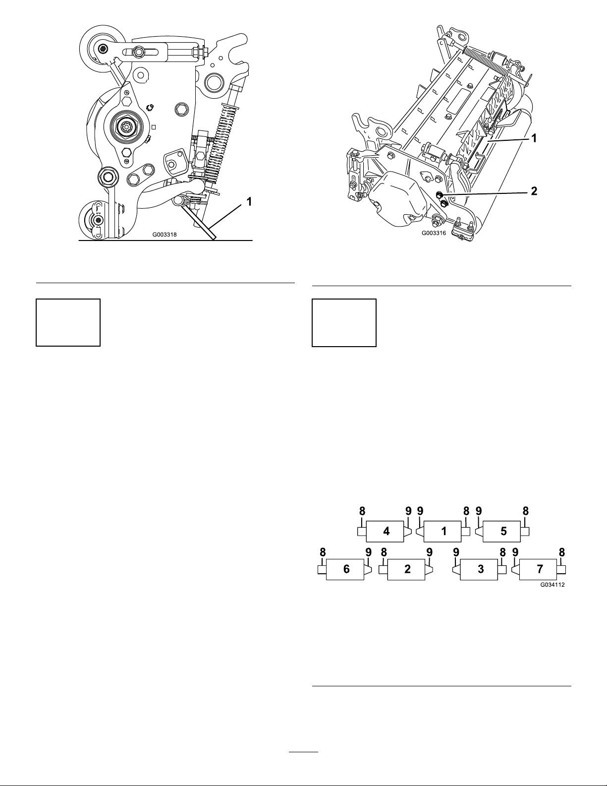
Figure9
Figure10
1.Kickstand
5
AdjustingtheRearShield
NoPartsRequired
Procedure
Undermostconditions,bestdispersionisattainedwhenthe
rearshieldisclosed(frontdischarge).Whenconditionsare
heavyorwet,therearshieldmaybeopened.
Toopentherearshield(Figure10),loosenthecapscrew
securingtheshieldtotheleftsideplate,rotatetheshieldto
theopenposition,andtightenthecapscrew.
1.Rearshield
2.Capscrew
6
MountingtheCounterweights
NoPartsRequired
Procedure
Allcuttingunitsareshippedwiththecounterweightmounted
totheleftendofthecuttingunit.Usethefollowingdiagram
todeterminethepositionofthecounterweightsandreel
motors.
Note:Sometractionunitshaveonly5cuttingunits.
Figure11
1.Cuttingunit16.Cuttingunit6
2.Cuttingunit27.Cuttingunit7
3.Cuttingunit3
4.Cuttingunit4
5.Cuttingunit5
1.Oncuttingunitnumbers2,4,and6,removethe2
capscrewssecuringthecounterweighttotheleftend
ofthecuttingunit.
7
8.Reelmotor
9.Weight
Page 8
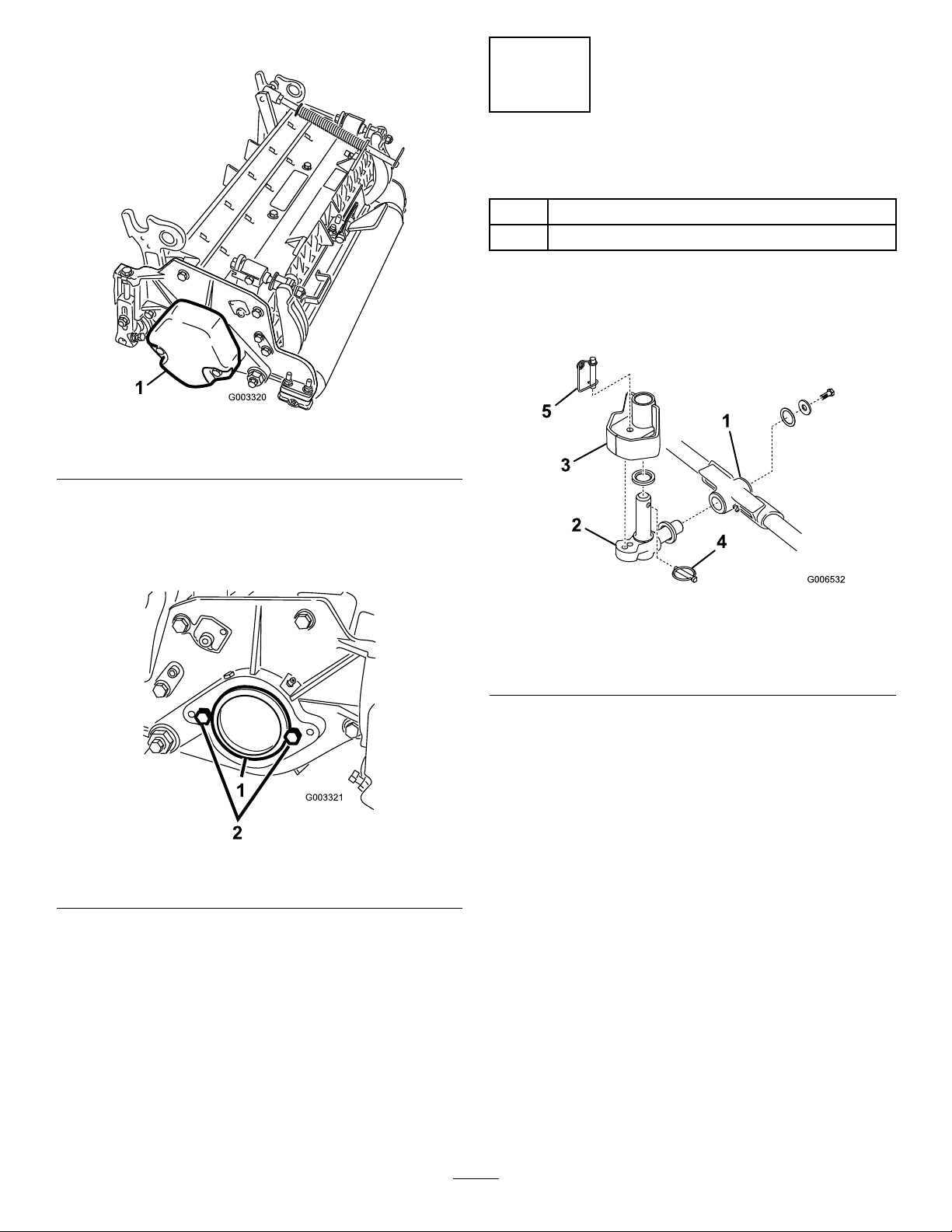
Note:Removethecounterweight(Figure12).
G003321
1
2
Figure12
1.Counterweight
7
InstallingtheCuttingUnits
Partsneededforthisprocedure:
5/7LargeO-ring
2
Screw
Procedure
1.Insertathrustwasherontothehorizontalshaftofthe
pivotknuckleasshowninFigure14.
2.Ontherightendofthecuttingunit,removetheplastic
plugfromthebearinghousing(Figure13).
3.Removethe2capscrewsfromtherightsideplate
(Figure13).
Figure13
1.Plasticplug
4.Installthecounterweighttotherightendofthecutting
unitwiththe2screwspreviouslyremoved.
5.Looselyinstallthe2reelmotormountingcapscrews
totheleftsideplateofthecuttingunit(Figure13).
2.Capscrew(2)
Figure14
1.Carrierframe
2.Pivotknuckle
3.Lift-armsteeringplate
2.Insertthehorizontalshaftofthepivotknuckleintothe
mountingtubeofthecarrierframe(Figure14).
3.Securepivotknuckletocarrierframewithathrust
washer,aatwasher,andaange-headcapscrew
(Figure14).
4.Insertathrustwasherontotheverticalshaftofthe
pivotknuckle(Figure14).
5.Ifremoved,inserttheverticalshaftofthepivotknuckle
intothelift-armpivothub(Figure14).
6.Guidethepivotknuckleinplacebetweenthe2rubber
centeringbumpersintheundersideofthelift-arm
steeringplate.
7.Insertthelynchpinintothecrossholeonthe
pivot-knuckleshaft(Figure14).
4.Lynchpin
5.Steeringlockingpin
8.Securetheliftarmchaintothecuttingunitchain
bracket(Figure15)withthesnapperpinasfollows:
•Oncuttingunitnumbers1,4,5,6,and7,useonly
6ofthechainlinks.
•Oncuttingunitnumbers2and3,useall7ofthe
chainlinks.
8
Page 9
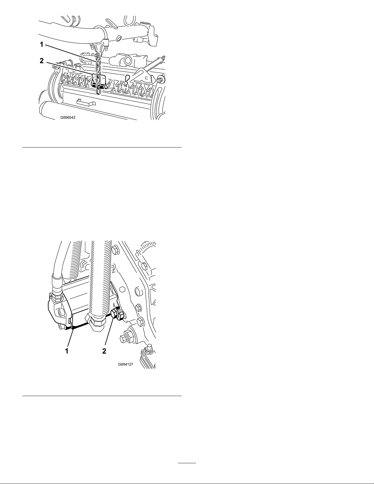
Figure15
1.Liftchain2.Snapperpin
9.Coatthesplineofthereelmotorwithcleangrease.
10.OilthereelmotorO-ringandinstallitontothemotor
ange.
11.Installthemotorbyrotatingitclockwisesothatthe
motorangesclearthecapscrews(Figure16).
12.Rotatethemotorcounterclockwiseuntiltheanges
encirclethecapscrewsandthentightenthecapscrews.
Important:Makesurethatthereelmotorhoses
arenottwisted,kinked,oratriskofbeingpinched.
Figure16
1.Reelmotor
2.Capscrew
Note:Ifaxedcuttingunitpositionisrequired,
insertthesteeringlockingpinintothepivotknuckle
mountinghole(Figure14).
13.Hookthespringwirearoundthebottomofthesteering
lockingpin(Figure14).
9
Page 10

ProductOverview
Specications
CuttingUnit
8blade
11blade
Weight
67kg(147lb)
69kg(151lb)
Attachments/Accessories
AselectionofToro-approvedattachmentsandaccessoriesis
availableforusewiththemachinetoenhanceandexpand
itscapabilities.ContactyourAuthorizedServiceDealeror
Distributororgotowww .Toro.comforalistofallapproved
attachmentsandaccessories
Tobestprotectyourinvestmentandmaintainoptimal
performanceofyourToroequipment,countonTorogenuine
parts.Whenitcomestoreliability ,Torodeliversreplacement
partsdesignedtotheexactengineeringspecicationofour
equipment.Forpeaceofmind,insistonT orogenuineparts.
Operation
Note:Determinetheleftandrightsidesofthemachine
fromthenormaloperatingposition.
MakingAdjustments
AdjustingtheBedknifetotheReel
Usethisproceduretosetthebedknifetothereelandtocheck
theconditionofthereelandbedknifeandtheirinteraction.
Aftercompletingthisprocedure,alwaystestthecutting
unitperformanceunderyoureldconditions.Youmay
needtomakefurtheradjustmentstoobtainoptimalcutting
performance.
Important:Donotovertightenthebedknifetothereel
oryouwilldamageit.
•Afterbacklappingthecuttingunitorgrindingthereel,you
mayneedtomowwiththecuttingunitforafewminutes
andthenperformthisproceduretoadjustthebedknifeto
thereelasthereelandbedknifeadjusttoeachother.
•Youmayneedadditionaladjustmentsiftheturfis
extremelydenseoryourcuttingheightisverylow .
Youwillneedthefollowingtoolstocompletethisprocedure:
•Shim,0.0508mm(0.002inch)—ToroPartNo.125-5611
•Cuttingperformancepaper—ToroPartNo.125-5610
1.Positionthecuttingunitonaat,levelworksurface.
Turnthebedbar-adjustingscrewscounterclockwise
toensurethatthebedbardoesnotcontactthereel
(Figure17).
Figure17
1.Bedbar-adjustingscrew
2.Tipthemowertoexposethebedknifeandthereel.
Important:Makesurethatthenutsontheback
endofthebedbar-adjustingscrewsarenotresting
ontheworksurface(Figure18).
10
Page 11

g020158
1.Cutting-unitkickstand
preventstheshimfrompassingthroughonbothsides.
Thebedknifeisnowparalleltothereel.
Note:Thisprocedureshouldnotbeneededondaily
adjustments,butshouldbedoneaftergrindingor
disassembly.
9.Fromthisposition(i.e.,1clickinandshimnotpassing
through)turnthebedbaradjustersclockwise1click
each.
Note:Eachclickturnedmovesthebedknife0.022
(0.0009inches).Donotovertightentheadjusting
screws.
10.Testthecuttingperformancebyinsertingalongstrip
ofcuttingperformancepaper(T oropartnumber
125-5610)betweenreelandbedknife,perpendicular
tothebedknife(Figure19).Slowlyrotatethereel
forward;itshouldcutthepaper.
Figure18
3.Rotatethereelsothatabladecrossesthebedknife
approximately25mm(1inch)infromtheendof
thebedknifeontherighthandsideofthecutting
unit.Puttinganidentifyingmarkonthisblademakes
subsequentadjustmentseasier.Insertthe0.05mm
(0.002inch)shimbetweenthemarkedreelbladeand
thebedknifeatthepointwherethebladecrossesthe
bedknife.
4.Turntherightbedbaradjusterclockwiseuntilyoufeel
lightpressure(i.e.,drag)ontheshim,thenbackoffthe
bedbaradjuster2clicksandremovetheshim.
Note:Becauseadjusting1sideofthecuttingunit
affectstheotherside,the2clicksprovideclearancefor
whentheothersideisadjusted.
Note:Ifstartingwithalargegap,bothsidesshould
initiallybedrawncloserbyalternatelytighteningthe
rightandleftsides.
5.Slowlyrotatethereelsothatthesamebladethatyou
checkedontherightsideiscrossingthebedknife
approximately25mm(1inch)infromtheendofthe
bedknifeontheleftsideofthecuttingunit.
6.Turntheleftbedbaradjusterclockwiseuntiltheshim
canbeslidthroughthereeltobedknifegapwithlight
drag.
Figure19
Note:Ifexcessivereeldragoccurseitherbacklap
orgrindthecuttingunittoachievethesharpedges
neededforprecisioncutting.
AdjustingtheRearRoller
1.Adjusttherearrollerbrackets(Figure20)tothedesired
height-of-cutrangebypositioningtherequiredamount
ofspacersbelowtheside-platemountingange(Figure
20)pertheHOCChart.
7.Returntotherightsideandadjustasnecessarytoget
lightdragontheshimbetweenthesamebladeand
bedknife.
8.Repeatsteps6and7untiltheshimcanbeslidthrough
bothgapswithslightdrag,but1clickinoneachside
Figure20
1.Spacer3.Side-platemountingange
2.Rollerbracket
11
Page 12

2.Raisetherearofthecuttingunitandplaceablock
g020552
underthebedknife.
3.Removethe2nutssecuringeachrollerbracketand
spacertoeachside-platemountingange.
4.Lowertherollerandscrewsfromtheside-plate
mountingangesandspacers.
5.Placethespacersontothescrewsontherollerbrackets.
6.Securetherollerbracketandspacerstotheunderside
oftheside-platemountingangeswiththenuts
previouslyremoved.
7.Verifythatthebedknife-to-reelcontactiscorrect.Tip
themowertoexposethefrontandrearrollersandthe
bedknife.
Note:Thepositionoftherearrollertothereel
iscontrolledbythemachiningtolerancesofthe
assembledcomponentsandparallelingisnotrequired.
Alimitedamountofadjustmentispossiblebysetting
thecuttingunitonasurfaceplateandlooseningthe
side-platemountingcapscrews(Figure21).
EffectiveHeightofCut
Thisistheactualheightthatthegrasshasbeencut.Fora
givenbenchsetheightofcut,theactualheightofcutwill
varydependingonthetypeofgrass,timeofyear,turf,and
soilconditions.Thecuttingunitsetup(aggressivenessofcut,
rollers,bedknives,attachmentsinstalled,turfcompensation
settings,etc.)willalsoaffecttheeffectiveheightofcut.Check
theeffectiveheightofcutusingtheTurfEvaluator(Model
04399)regularlytodeterminethedesiredbenchsetheight
ofcut.
AggressivenessofCut
Aggressivenessofcuthasasignicantimpactonthe
performanceofthecuttingunit.Aggressivenessofcutrefers
totheangleofthebedkniferelativetotheground(Figure22).
Thebestcuttingunitsetupisdependentonyourturf
conditionsanddesiredresults.Experiencewiththecutting
unitonyourturfwilldeterminethebestsettingtouse.
Aggressivenessofcutmaybeadjustedthroughoutthecutting
seasontoallowforvariousturfconditions.
Ingeneral,lesstonormalaggressivesettingsaremore
appropriateforwarm-seasongrasses(Bermuda,paspalum,
zoysia)whilecool-seasongrasses(bent,bluegrass,rye)may
requirenormaltomoreaggressivesetups.Moreaggressive
setupscutmoregrassoffbyallowingthespinningreeltopull
moregrassupintothebedknife.
Figure21
1.Side-platemountingcapscrews
8.Adjustandtightenthecapscrewsandtorquethecap
screwsto27to36N∙m(240to320in-lb).
Height-of-CutChartTerms
Height-of-CutSetting(HOC)
Thiscorrespondstothedesiredheightofcut.
BenchSetHeightofCut
Thebenchsetheightofcutistheheightatwhichthetop
edgeofthebedknifeissetaboveaatlevelsurfacethat
contactsthebottomofboththefrontandrearroller.
Figure22
1.Rearspacers
2.Side-platemountingange
3.Aggressivenessofcut
RearSpacers
Thenumberofrearspacersdeterminestheaggressiveness
ofcutforthecuttingunit.Foragivenheightofcut,adding
spacers,belowtheside-platemountingange,increasesthe
aggressivenessofthecuttingunit.Allcuttingunitsona
givenmachinemustbesettothesameaggressivenessofcut
(numberofrearspacers,PartNo.119-0626),otherwisethe
after-cutappearancecouldbenegativelyaffected(Figure22).
12
Page 13

Turf-CompensationSettings
Theturf-compensationspringtransferstheweightfromthe
fronttotherearroller.Thishelpstoreduceawavepatternin
theturf,alsoknownasmarcellingorbobbing.
Important:Makespringadjustmentswiththecutting
unitmountedtothetractionunit,pointingstraight
aheadandloweredtotheshopoor.
1.Makesurethatthehairpincotterisinstalledintherear
holeinthespringrod(Figure23).
Figure23
1.Turf-compensationspring3.Springrod
2.Hairpincotter4.Hexnuts
2.Tightenthehexnutsonthefrontendofthespringrod
untilthecompressedlengthofthespringis15.9cm
(6.25inches);refertoFigure23.
Note:Whenoperatingonroughterraindecreasethe
springlengthby12.7mm(0.5inch).Groundfollowing
willbeslightlyshorter.
Note:Youmustresettheturf-compensationsettingif
theHOCsettingortheaggressiveness-of-cutsetting
ischanged.
Groomer
Thesearetherecommendedheight-of-cutsettingswhena
groomerkitisinstalledonthecuttingunit.
13
Page 14

Height-of-CutChart
HOCSettingAggressivenessofCutNo.ofRearSpacersWithGroomerKitsInstalled
0.64cm(0.250inches)
0.95cm(0.375inches)
1.27cm(0.500inches)
1.56cm(0.625inches)
1.91cm(0.750inches)
2.22cm(0.875inches)
2.54cm(1.000inches)
2.86cm(1.125inches)
3.18cm(1.250inches)*+
3.49cm(1.375inches)*+
3.81cm(1.500inches)*+
4.13cm(1.625inches)*+
4.44cm(1.750inches)*+
4.76cm(1.875inches)*+
5.08cm(2.000inches)*+
*TheHighHOCKit(PartNo.110-9600)mustbeinstalled.FrontHOCbracketmustbepositionedinthetopside-platehole.
+WhentheHeightofCutisabove2.54cm(1inch)andarearrollerbrushisused,theHighHeight-of-CutBrushisrequiredand
theoptionalSteeringCylinder,PartNo.105-9275shouldbeinstalledtopreventcontactbetweenthereartireandthebrush
whenmakingextremeturns.
Less
Normal
More
Less
Normal
More
Less
Normal
More
Less
Normal
More
Less
Normal
More
Less
Normal
More
Less
Normal
More
Less
Normal
More
Less
Normal
More
Less
Normal
More
Less
Normal
More
Less
Normal
More
Less
Normal
More
Less
Normal
More
Less
Normal
More
0
0
1
0
1
2
0
1
2
1
2
3
2
3
4
2
3
4
3
4
5
4
5
6
4
5
6
4
5
6
5
6
7
6
7
8
6
7
8
7
8
9
7
8
9
Y
Y
-
Y
Y
-
Y
Y
Y
Y
Y
-
Y
Y
-
Y
Y
-
Y
Y
-
-
-
-
-
-
-
-
-
-
-
-
-
-
-
-
-
-
-
-
-
-
-
-
-
14
Page 15

AdjustingtheHeightofCut
Note:Forheightsofcutgreaterthan2.54cm(1.00inch)
installtheHighHeight-of-CutKit.
1.Loosenthelocknutssecuringtheheight-of-cutarmsto
thecutting-unitsideplates(Figure24).
Figure24
1.Adjustingscrew
2.Locknut
2.Loosenthenutonthegaugebar(Figure25)andsetthe
adjustingscrewtothedesiredheightofcut.
3.Height-of-cutarm
Figure26
Important:Whensetproperly,therearandfront
rollerswillcontactthegaugebarandthescrew
willbesnugagainstthebedknife.Thisensures
thattheheightofcutisidenticalatbothendsof
thebedknife.
6.Tightenthenutstosecuretheadjustment.Donot
overtightenthenuts.Tightenthemjustenoughto
removeplayfromthewasher.
Figure25
1.Gaugebar4.Holesusedforsetting
GroomerHOC
2.Height-adjustingscrew5.Holenotused
3.Nut
3.Measurethedistancebetweenthebottomofthescrew
headandthefaceofthebartogettheheightofcut.
4.Hookthescrewheadonthecuttingedgeofthe
bedknifeandresttherearendofthebarontherear
roller(Figure26).
5.Rotatetheadjustingscrewuntilthefrontrollercontacts
thegaugebar(Figure26).Adjustbothendsofroller
untiltheentirerollerisparalleltothebedknife.
15
Page 16

Usethefollowingcharttodeterminewhichbedknifeisbestsuitedforthedesiredheightofcut.
Bedknife/HeightofCutChart
Bedknife
LowHOC(Optional)
EdgeMax®LowHOC
(Optional)
ExtendedLowHOC
(Optional)
ExtendedEdgeMax®Low
HOC(Optional)
EdgeMax®
(Models03698and03699)
Standard(Optional)
HeavyDuty(Optional)
*Warm-seasongrassesmayrequiretheLowHOCbedknifefor12.7mm(0.500inch)andbelow.
PartNo.
110-40845.6mm
127-71325.6mm
120-16405.6mm
119-42805.6mm
108-90956.9mm
108-90966.9mm
110-40749.3mm
BedknifeLipHeightHeightofCut
(0.220inch)
(0.220inch)
(0.220inch)
(0.220inch)
(0.270inch)
(0.270inch)
(0.370inch)
Note:Theadjustmentknobshavedetents
correspondingto0.023mm(0.0009inch)bedknife
movementforeachindexedposition.
6.4to12.7mm
(0.250to0.500inch)
6.4to-12.7mm
(0.250to0.500inch)
6.4to12.7mm
(0.250to0.500inch)
6.4to12.7mm
(0.250to0.500inch)
9.5to38.1mm
(0.375to1.50inches)*
9.5to38.1mm
(0.375to1.50inches)*
12.7to38.1mm
(0.500to1.50inches)
Figure27
1.Bedknifelipheight
CheckingandAdjustingtheCutting
Unit
Thedualknobbedknife-to-reeladjustmentsystem
incorporatedinthiscuttingunitsimpliestheadjustment
procedureneededtodeliveroptimummowingperformance.
Thepreciseadjustmentpossiblewiththedualknob/bedbar
designgivesthenecessarycontroltoprovideacontinual
self-sharpeningaction—thusmaintainingsharpcuttingedges,
ensuringgoodqualityofcut,andgreatlyreducingtheneed
forroutinebacklapping.
Priortomowingeachday,orasrequired,checkeachcutting
unittoverifyproperbedknife-to-reelcontact.Thismust
beperformedregardlessofwhetherthequalityofcutis
acceptable.
1.Lowerthecuttingunitsontoahardsurface,shutoff
theengine,andremovetheignitionkey.
2.Slowlyrotatethereelinareversedirection,listening
forreel-to-bedknifecontact.Ifnocontactisevident,
turnthebedknifeadjustingknobsclockwise,1clickat
atime,untilyoufeelandhearlightcontact.
3.Ifexcessivecontact/reeldragisevident,eitherbacklap,
refacethefrontofthebedknife,orgrindthecutting
unittoachievethesharpedgesneededforprecision
cutting;refertotheToroManualforSharpeningReeland
RotaryMowers,FormNo.09168SL.
Important:Lightcontactispreferredatalltimes.
Iflightcontactisnotmaintained,thebedknife/reel
edgeswillnotsufcientlyself-sharpenanddull
cuttingedgeswillresultafteraperiodofoperation.
Ifexcessivecontactismaintained,bedknife/reel
wearwillbeaccelerated,unevenwearcanresult,
andqualityofcutmaybeadverselyaffected.
Note:Asthereelbladescontinuetorunagainstthe
bedknife,aslightburrwillappearonthefrontcutting
edgesurfacealongthefulllengthofthebedknife.To
improvethecuttingperformance,occasionallyruna
leacrossthefrontedgetoremovethisburr.
Afterextendedrunning,aridgewilleventuallydevelop
atbothendsofthebedknife.Youmustroundoffthese
notchesorlethemushwiththecuttingedgeofthe
bedknifetoensuresmoothoperation.
Note:Overtime,thechamfer(Figure28)willneed
tobegroundasitisonlydesignedtolast40%ofthe
bedknifelife.
Note:Thereelmustcutonesheetofpaper,when
insertedatarightangletothebedknife,atbothends
andthecenterofthereel.
16
Page 17

Figure28
1.Lead-inchamferonright
endofbedknife
2.6mm(0.25inch)
3.1.5mm(0.060inch)
Note:Donotmakelead-inchamfertoolargeasit
maycauseturftufting.
17
Page 18

Maintenance
g020697
LubricatingtheCuttingUnit
Eachcuttingunithas6greasettings(Figure29)thatmust
belubricatedregularlywithNo.2lithiumgrease.
Thelubricationpointsincludethefrontroller(2),therear
roller(2),andthereelbearing(2).
1.Wipeeachgreasettingwithacleanrag.
2.Applygreaseuntilcleangreasecomesoutoftheroller
sealsandthebearingreliefvalve.
3.Wipeanyexcessgreaseaway .
2.Usingaragorathicklypaddedglove,holdontothe
reelbladeandtrytomovethereelassemblysideto
side(Figure31).
Figure31
3.Ifendplayexists,proceededasfollows:
A.Loosentheexternalsetscrewsecuringthebearing
adjusternuttobearinghousinglocatedontheleft
sideofthecuttingunit(Figure32).
Figure29
1.Reliefvalve
AdjustingtheReelBearings
Toensurelonglifeofthereelbearings,periodicallycheck
ifreelendplayexists.Youcancheckandadjustthereel
bearingsasfollows:
1.Loosenthereel-to-bedknifecontactbyturningthe
bedknifeadjustingknobs(Figure30)counterclockwise
untilnocontactexists.
Figure32
1.Setscrew
B.Usinga1-3/8inchsocketwrench,slowlytighten
thereel-bearingadjustmentnutuntilnoendplay
ofthereelexists.Ifadjustingthenutdoesnot
eliminatereelendplay,replacethereelbearings.
Note:Thereelbearingsdonotrequirepreload.
Overtighteningthereel-bearingadjusternutwill
damagethereelbearings.
4.Tightenthesetscrewsecuringthebearingadjusternut
tothebearinghousing.
Note:Torquethenutto1.4to1.7N∙m(12to15
in-lb).
2.Adjusternut
1.Bedknife-adjusterknob
Figure30
18
Page 19

ServicingtheBedknife
2
3
g027268
1
Thebedknifeservicelimitsarelistedinthefollowingchart.
Important:Operatingthecuttingunitwiththebedknifebelowtheservicelimitmayresultinpoorafter-cut
appearanceandreducethestructuralintegrityofthebedknifeforimpacts.
BedknifeServiceLimitChart
Bedknife
EdgeMax®LowHOC
(Optional)
LowHOC(Optional)
ExtendedEdgeMax®
LowHOC(Optional)
ExtendedLowHOC
(Optional)
EdgeMax®
(Models03698and
03699)
Standard(Optional)
HeavyDuty(Optional)
Part
127-71325.6mm
110-40845.6mm
119-42805.6mm
120-16405.6mm
108-90956.9mm
108-90966.9mm
110-40749.3mm
Figure33
RecommendedTopandFrontBedknifeGrindAngles
1.Bedknifeservicelimit*
2.Topgrindangle
3.Frontgrindangle
BedknifeLipHeight*ServiceLimit*GrindAngles
(0.220inch)
(0.220inch)
(0.220inch)
(0.220inch)
(0.270inch)
(0.270inch)
(0.370inch)
6.4to12.7mm
(0.250to0.500inch)
4.8mm
(0.190inch)
4.8mm
(0.190inch)
4.8mm
(0.190inch)
4.8mm
(0.190inch)
4.8mm
(0.190inch)
4.8mm
(0.190inch)
CheckingtheTopGrindAngle
Theanglethatyouusetogrindyourbedknivesisvery
important.
Usetheangleindicator(ToroPartNo.131-6828)andthe
angle-indicatormount(ToroPartNo.131-6829)tocheck
theanglethatyourgrinderproducesandthencorrectfor
anygrinderinaccuracy .
1.Placetheangleindicatoronthebottomsideofthe
bedknifeasshowninFigure35.
Top/FrontAngles
10/5degrees
10/5degrees
10/10degrees
10/10degrees
10/5degrees
10/5degrees
10/5degrees
Note:Allbedknifeservicelimitmeasurementsrelatetothe
bottomofthebedknife(Figure34).
Figure34
Figure35
1.Bedknife(vertical)
2.Angleindicator
2.PresstheAltZerobuttonontheangleindicator.
3.Placetheangle-indicatormountontheedgeofthe
bedknifesothattheedgeofthemagnetismatedwith
theedgeofthebedknife(Figure36).
Note:Thedigitaldisplayshouldbevisiblefromthe
samesideduringthisstepasitwasinstep1.
19
Page 20

Figure36
ServicingtheBedbar
RemovingtheBedbar
1.Turnthebedbar-adjustingscrewscounterclockwiseto
backthebedknifeawayfromthereel(Figure37).
1.Angle-indicatormount
2.Edgeofthemagnetmated
withtheedgeofthe
bedknife
3.Bedknife
4.Angleindicator
4.Placetheangleindicatoronthemountasshownin
Figure36.
Note:Thisistheanglethatyourgrinderproduces;it
shouldbewithin2degreesoftherecommendedtop
grindangle.
Figure37
1.Bedbar-adjustingscrew3.Bedbar
2.Spring-tensionnut
4.Washer
2.Backoutthespring-tensionnutuntilthewasherisno
longertensionedagainstthebedbar(Figure37).
3.Oneachsideofthemachine,loosenthelocknut
securingthebedbarbolt(Figure38).
Figure38
1.Bedbarbolt2.Locknut
4.Removeeachbedbarbolt,allowingthebedbarto
bepulleddownwardandremovedfromthemachine
bolt(Figure38).Accountfor2nylonwashersand
1stampedsteelwasheroneachendofthebedbar
(Figure39).
20
Page 21

Figure39
1.Bedbarbolt
2.Nut4.Nylonwasher
3.Steelwasher
AssemblingtheBedbar
1.Installthebedbar,positioningthemountingears
betweenthewasherandthebedbaradjuster.
2.Securethebedbartoeachsideplatewiththebedbar
bolts(nutsonbolts)and6washers.
Note:Positionanylonwasheroneachsideof
side-plateboss.Placeasteelwasheroutsideeachofthe
nylonwashers(Figure39).
3.Torquethebedbarboltsto27to36N∙m(240to320
in-lb).
Note:Tightenthelocknutsuntiltheoutsidesteel
washerstopsrotatingandendplayisremoved,butdo
notovertightenordeectthesideplates.Thewashers
ontheinsidemayhaveagap.
4.Tightenthespring-tensionnutuntilthespringis
collapsed,thenbackoff1/2turn(Figure40).
Figure40
1.Spring-tensionnut2.Spring
21
Page 22

ServicingtheRoller
TheRollerRebuildKit(PartNo.114-5430)and
theRollerRebuildToolKit(PartNo.115-0803)
(Figure41)areavailableforservicingtheroller.The
RollerRebuildKitincludesallthebearings,bearing
nuts,innerseals,andoutersealstorebuildaroller.
TheRollerRebuildToolKitincludesallthetoolsandthe
installationinstructionsrequiredtorebuildarollerwiththe
rollerrebuildkit.Refertoyourpartscatalogorcontactyour
AuthorizedToroDistributorforassistance.
Figure41
1.RollerRebuildKit(PartNo.114-5430)
2.RollerRebuildT oolkit(PartNo.1 15-0803)
3.Innerseal8.Washer
4.Bearing
5.Outerseal
6.Bearingnut
7.Innersealtool
9.Bearing/outer-sealtool
22
Page 23

Notes:
23
Page 24

Notes:
24
Page 25

Notes:
25
Page 26

DeclarationofIncorporation
TheT oroCompany,811 1LyndaleAve.South,Bloomington,MN,USAdeclaresthatthefollowingunit(s)
conform(s)tothedirectiveslisted,wheninstalledinaccordancewiththeaccompanyinginstructionsontocertain
ToromodelsasindicatedontherelevantDeclarationsofConformity.
ModelNo.
03698316000001andUp
03699316000001andUp
SerialNo.
ProductDescriptionInvoiceDescription
8-bladeDPACuttingUnit
forReelmaster6000Series
TractionUnit
11-bladeDP ACuttingUnit
forReelmaster6000Series
TractionUnit
7"8BLADEDPA(RADIAL)
CU-RM6500/6700
7"11BLADEDPA(RADIAL)
CU-RM6500/6700
GeneralDescription
CuttingUnit
CuttingUnit
Directive
2000/14/EC
2006/42/EC
2000/14/EC
2006/42/EC
RelevanttechnicaldocumentationhasbeencompiledasrequiredperPartBofAnnexVIIof2006/42/EC.
Wewillundertaketotransmit,inresponsetorequestsbynationalauthorities,relevantinformationonthispartly
completedmachinery.Themethodoftransmissionshallbeelectronictransmittal.
ThismachineryshallnotbeputintoserviceuntilincorporatedintoapprovedToromodelsasindicatedonthe
associatedDeclarationofConformityandinaccordancewithallinstructions,wherebyitcanbedeclaredin
conformitywithallrelevantDirectives.
Certied:EUTechnicalContact:
MarcelDutrieux
ManagerEuropeanProductIntegrity
ToroEuropeNV
Nijverheidsstraat5
2260Oevel
DavidKlisBelgium
Sr.EngineeringManager
811 1LyndaleAve.South
Bloomington,MN55420,USA
January4,2016
Tel.+3216386659
26
Page 27

InternationalDistributorList
Distributor:
AgrolancKft
AsianAmericanIndustrial(AAI)
B-RayCorporation
BrisaGoodsLLC
CascoSalesCompany
CeresS.A.CostaRica
CSSCTurfEquipment(pvt)Ltd.SriLanka
CyrilJohnston&Co.
CyrilJohnston&Co.RepublicofIreland
FatDragon
FemcoS.A.Guatemala
FIVEMANSNew-T echCo.,LtdChina
ForGarderOU
G.Y .K.CompanyLtd.
GeomechanikiofAthensGreece
GolfinternationalTurizm
HakoGroundandGardenSweden
HakoGroundandGarden
HayterLimited(U.K.)
HydroturfInt.CoDubai
HydroturfEgyptLLC
IrrimacPortugal351212388260T oroEuropeNVBelgium3214562960
IrrigationProductsInt'lPvtLtd.India00914424494387ValtechMorocco212537663636
JeanHeybroekb.v.Netherlands31306394611VictusEmakPoland48618238369
Country:
Hungary3627539640
HongKong85224977804
Korea82325512076
Mexico12104952417
PuertoRico7877888383
NorthernIreland442890813121
China
Estonia3723846060
Japan81726325861Riversa
Turkey902163365993
Norway4722907760
UnitedKingdom441279723444
UnitedArabEmirates97143479479T-MarktLogisticsLtd.Hungary3626525500
Egypt2025194308ToroAustraliaAustralia61395807355
PhoneNumber:Distributor:
MaquiverS.A.Colombia
MaruyamaMfg.Co.Inc.
Mountelda.s.CzechRepublic
Mountelda.s.Slovakia
5062391138
94112746100
442890813121ParklandProductsLtd.NewZealand6433493760
8861080841322
5024423277
86-10-63816136
30109350054
4635100000
MunditolS.A.
NormaGarden
OslingerTurfEquipmentSA
OyHakoGroundandGardenAb
Perfetto
PratoverdeSRL.
Prochaska&Cie
RTCohen2004Ltd.
LelyTurfcare
Lely(U.K.)Limited
SolvertS.A.S.
SpyprosStavrinidesLimitedCyprus
SurgeSystemsIndiaLimited
Country:
Japan81332522285
Argentina541 148219999
Russia749541 16120
Ecuador59342396970
Finland35898700733
Poland48618208416
Italy390499128128
Austria4312785100
Israel97298617979
Spain
Denmark4566109200
UnitedKingdom441480226800
France33130817700
India911292299901
PhoneNumber:
5712364079
420255704220
420255704220
34952837500
35722434131
EuropeanPrivacyNotice
TheInformationToroCollects
ToroWarrantyCompany(Toro)respectsyourprivacy.Inordertoprocessyourwarrantyclaimandcontactyouintheeventofaproductrecall,weaskyou
tosharecertainpersonalinformationwithus,eitherdirectlyorthroughyourlocalT orocompanyordealer.
TheT orowarrantysystemishostedonserverslocatedwithintheUnitedStateswhereprivacylawmaynotprovidethesameprotectionasapplies
inyourcountry.
BYSHARINGYOURPERSONALINFORMATIONWITHUS,YOUARECONSENTINGTOTHEPROCESSINGOFYOURPERSONALINFORMATION
ASDESCRIBEDINTHISPRIV ACYNOTICE.
TheWayT oroUsesInformation
Toromayuseyourpersonalinformationtoprocesswarrantyclaims,tocontactyouintheeventofaproductrecallandforanyotherpurposewhichwetell
youabout.ToromayshareyourinformationwithT oro'safliates,dealersorotherbusinesspartnersinconnectionwithanyoftheseactivities.Wewillnot
sellyourpersonalinformationtoanyothercompany.Wereservetherighttodisclosepersonalinformationinordertocomplywithapplicablelawsand
withrequestsbytheappropriateauthorities,tooperateoursystemsproperlyorforourownprotectionorthatofotherusers.
RetentionofyourPersonalInformation
Wewillkeepyourpersonalinformationaslongasweneeditforthepurposesforwhichitwasoriginallycollectedorforotherlegitimatepurposes
(suchasregulatorycompliance),orasrequiredbyapplicablelaw .
Toro'sCommitmenttoSecurityofYourPersonalInformation
Wetakereasonableprecautionsinordertoprotectthesecurityofyourpersonalinformation.Wealsotakestepstomaintaintheaccuracyandcurrent
statusofpersonalinformation.
AccessandCorrectionofyourPersonalInformation
Ifyouwouldliketorevieworcorrectyourpersonalinformation,pleasecontactusbyemailatlegal@toro.com.
AustralianConsumerLaw
AustraliancustomerswillnddetailsrelatingtotheAustralianConsumerLaweitherinsidetheboxoratyourlocalToroDealer.
374-0269RevK
Page 28

TheT oroWarranty
ATwo-YearLimitedWarranty
ConditionsandProductsCovered
TheToroCompanyanditsafliate,T oroWarrantyCompany,pursuant
toanagreementbetweenthem,jointlywarrantyourT oroCommercial
product(“Product”)tobefreefromdefectsinmaterialsorworkmanship
fortwoyearsor1500operationalhours*,whicheveroccursrst.This
warrantyisapplicabletoallproductswiththeexceptionofAerators
(refertoseparatewarrantystatementsfortheseproducts).Wherea
warrantableconditionexists,wewillrepairtheProductatnocosttoyou
includingdiagnostics,labor,parts,andtransportation.Thiswarranty
beginsonthedatetheProductisdeliveredtotheoriginalretailpurchaser .
*Productequippedwithanhourmeter.
InstructionsforObtainingWarrantyService
YouareresponsiblefornotifyingtheCommercialProductsDistributoror
AuthorizedCommercialProductsDealerfromwhomyoupurchasedthe
Productassoonasyoubelieveawarrantableconditionexists.Ifyouneed
helplocatingaCommercialProductsDistributororAuthorizedDealer,or
ifyouhavequestionsregardingyourwarrantyrightsorresponsibilities,
youmaycontactusat:
ToroCommercialProductsServiceDepartment
ToroWarrantyCompany
811 1LyndaleAvenueSouth
Bloomington,MN55420-1196
952–888–8801or800–952–2740
E-mail:commercial.warranty@toro.com
OwnerResponsibilities
AstheProductowner,youareresponsibleforrequiredmaintenanceand
adjustmentsstatedinyourOperator'sManual.Failuretoperformrequired
maintenanceandadjustmentscanbegroundsfordisallowingawarranty
claim.
ItemsandConditionsNotCovered
Notallproductfailuresormalfunctionsthatoccurduringthewarranty
periodaredefectsinmaterialsorworkmanship.Thiswarrantydoesnot
coverthefollowing:
•Productfailureswhichresultfromtheuseofnon-T ororeplacement
parts,orfrominstallationanduseofadd-on,ormodiednon-Toro
brandedaccessoriesandproducts.Aseparatewarrantymaybe
providedbythemanufactureroftheseitems.
•Productfailureswhichresultfromfailuretoperformrecommended
maintenanceand/oradjustments.Failuretoproperlymaintainyour
ToroproductpertheRecommendedMaintenancelistedinthe
Operator’sManualcanresultinclaimsforwarrantybeingdenied.
•ProductfailureswhichresultfromoperatingtheProductinanabusive,
negligent,orrecklessmanner.
•Partssubjecttoconsumptionthroughuseunlessfoundtobedefective.
Examplesofpartswhichareconsumed,orusedup,duringnormal
Productoperationinclude,butarenotlimitedto,brakepadsand
linings,clutchlinings,blades,reels,rollersandbearings(sealedor
greasable),bedknives,sparkplugs,castorwheelsandbearings,tires,
lters,belts,andcertainsprayercomponentssuchasdiaphragms,
nozzles,andcheckvalves,etc.
•Failurescausedbyoutsideinuence.Conditionsconsideredtobe
outsideinuenceinclude,butarenotlimitedto,weather,storage
practices,contamination,useofunapprovedfuels,coolants,lubricants,
additives,fertilizers,water,orchemicals,etc.
•Failureorperformanceissuesduetotheuseoffuels(e.g.gasoline,
diesel,orbiodiesel)thatdonotconformtotheirrespectiveindustry
standards.
•Normalnoise,vibration,wearandtear ,anddeterioration.
•Normal“wearandtear”includes,butisnotlimitedto,damagetoseats
duetowearorabrasion,wornpaintedsurfaces,scratcheddecalsor
windows,etc.
Parts
Partsscheduledforreplacementasrequiredmaintenancearewarranted
fortheperiodoftimeuptothescheduledreplacementtimeforthatpart.
Partsreplacedunderthiswarrantyarecoveredforthedurationofthe
originalproductwarrantyandbecomethepropertyofT oro.T orowillmake
thenaldecisionwhethertorepairanyexistingpartorassemblyorreplace
it.T oromayuseremanufacturedpartsforwarrantyrepairs.
DeepCycleandLithium-IonBatteryWarranty:
DeepcycleandLithium-Ionbatterieshaveaspeciedtotalnumberof
kilowatt-hourstheycandeliverduringtheirlifetime.Operating,recharging,
andmaintenancetechniquescanextendorreducetotalbatterylife.Asthe
batteriesinthisproductareconsumed,theamountofusefulworkbetween
chargingintervalswillslowlydecreaseuntilthebatteryiscompletelyworn
out.Replacementofwornoutbatteries,duetonormalconsumption,
istheresponsibilityoftheproductowner.Batteryreplacementmaybe
requiredduringthenormalproductwarrantyperiodatowner’sexpense.
Note:(Lithium-Ionbatteryonly):ALithium-Ionbatteryhasapartonly
proratedwarrantybeginningyear3throughyear5basedonthetime
inserviceandkilowatthoursused.RefertotheOperator'sManualfor
additionalinformation.
MaintenanceisatOwner’sExpense
Enginetune-up,lubrication,cleaningandpolishing,replacementoflters,
coolant,andcompletingrecommendedmaintenancearesomeofthe
normalservicesT oroproductsrequirethatareattheowner’sexpense.
GeneralConditions
RepairbyanAuthorizedToroDistributororDealerisyoursoleremedy
underthiswarranty.
NeitherTheToroCompanynorToroWarrantyCompanyisliablefor
indirect,incidentalorconsequentialdamagesinconnectionwiththe
useoftheToroProductscoveredbythiswarranty,includingany
costorexpenseofprovidingsubstituteequipmentorserviceduring
reasonableperiodsofmalfunctionornon-usependingcompletion
ofrepairsunderthiswarranty.ExceptfortheEmissionswarranty
referencedbelow,ifapplicable,thereisnootherexpresswarranty.All
impliedwarrantiesofmerchantabilityandtnessforusearelimitedto
thedurationofthisexpresswarranty.
Somestatesdonotallowexclusionsofincidentalorconsequential
damages,orlimitationsonhowlonganimpliedwarrantylasts,sotheabove
exclusionsandlimitationsmaynotapplytoyou.Thiswarrantygivesyou
speciclegalrights,andyoumayalsohaveotherrightswhichvaryfrom
statetostate.
Noteregardingenginewarranty:
TheEmissionsControlSystemonyourProductmaybecoveredby
aseparatewarrantymeetingrequirementsestablishedbytheU.S.
EnvironmentalProtectionAgency(EP A)and/ortheCaliforniaAirResources
Board(CARB).Thehourlimitationssetforthabovedonotapplytothe
EmissionsControlSystemWarranty.RefertotheEngineEmissionControl
WarrantyStatementsuppliedwithyourproductorcontainedintheengine
manufacturer’sdocumentationfordetails
CountriesOtherthantheUnitedStatesorCanada
CustomerswhohavepurchasedT oroproductsexportedfromtheUnitedStatesorCanadashouldcontacttheirT oroDistributor(Dealer)toobtain
guaranteepoliciesforyourcountry ,province,orstate.IfforanyreasonyouaredissatisedwithyourDistributor'sserviceorhavedifcultyobtaining
guaranteeinformation,contacttheT oroimporter.
374-0253RevD
 Loading...