

Page 1

FormNo.3401-110RevA
Reelmaster
ModelNo.03678—SerialNo.316000501andUp
®
5610TractionUnit
Registeratwww.T oro.com.
OriginalInstructions(EN)
*3401-110*A
Page 2
ThisproductcomplieswithallrelevantEuropeandirectives,
fordetailspleaseseetheseparateproductspecicDeclaration
ofConformity(DOC)sheet.
WARNING
CALIFORNIA
Proposition65Warning
Thisproductcontainsachemicalorchemicals
knowntotheStateofCaliforniatocausecancer,
birthdefects,orreproductiveharm.
Dieselengineexhaustandsomeofits
constituentsareknowntotheStateof
Californiatocausecancer,birthdefects,
andotherreproductiveharm.
ItisaviolationofCaliforniaPublicResourceCode
Section4442or4443touseoroperatetheengineonany
forest-covered,brush-covered,orgrass-coveredlandunless
theengineisequippedwithasparkarrester,asdenedin
Section4442,maintainedineffectiveworkingorderorthe
engineisconstructed,equipped,andmaintainedforthe
preventionofre.
Thismanualidentiespotentialhazardsandhassafety
messagesidentiedbythesafety-alertsymbol(Figure1),
whichsignalsahazardthatmaycauseseriousinjuryordeath
ifyoudonotfollowtherecommendedprecautions.
Figure1
1.Safety-alertsymbol
Thismanualuses2wordstohighlightinformation.
Importantcallsattentiontospecialmechanicalinformation
andNoteemphasizesgeneralinformationworthyofspecial
attention.
Introduction
Thismachineisaride-on,reel-bladelawnmowerintended
tobeusedbyprofessional,hiredoperatorsincommercial
applications.Itisprimarilydesignedforcuttinggrasson
well-maintainedlawnsingolfcourses,parks,sportselds,
andoncommercialgrounds.Itisnotdesignedforcutting
brush,mowinggrassandothergrowthalongsidehighways,
orforagriculturaluses.
Readthisinformationcarefullytolearnhowtooperateand
maintainyourproductproperlyandtoavoidinjuryand
productdamage.Youareresponsibleforoperatingthe
productproperlyandsafely.
YoumaycontactTorodirectlyatwww .Toro.comforproduct
andaccessoryinformation,helpndingadealer,ortoregister
yourproduct.
Wheneveryouneedservice,genuineT oroparts,oradditional
information,contactanAuthorizedServiceDealerorToro
CustomerServiceandhavethemodelandserialnumbersof
yourproductready.Themodelandserialnumbersareona
platemountedontheleftsideoftheframeunderthefoot
rest.Writethenumbersinthespaceprovided.
ModelNo.
SerialNo.
©2015—TheToro®Company
8111LyndaleAvenueSouth
Bloomington,MN55420
Contactusatwww.Toro.com.
2
PrintedintheUSA
AllRightsReserved
Page 3

Contents
Safety...........................................................................4
SafeOperatingPractices...........................................4
ToroRidingMowerSafety........................................6
SoundPowerLevel..................................................7
SoundPressureLevel...............................................7
VibrationLevel......................................................7
SafetyandInstructionalDecals.................................7
Setup...........................................................................12
1AdjustingtheTirePressure....................................12
2AdjustingtheControl-ArmPosition.......................12
3InstallingtheCuttingUnits....................................13
4AdjustingtheTurf-CompensationSpring................16
5InstallingRearWeights.........................................17
6InstallingtheCEHoodLatch................................18
7UsingtheCutting-UnitKickstand...........................18
ProductOverview.........................................................19
Controls...............................................................19
Specications........................................................24
Attachments/Accessories........................................24
Operation....................................................................25
CheckingtheEngine-OilLevel.................................25
CheckingtheCoolingSystem...................................26
AddingFuel...........................................................26
CheckingtheHydraulicFluid...................................27
CheckingtheReel-to-BedknifeContact.....................28
CheckingtheTorqueoftheWheelNuts.....................28
BreakingintheMachine..........................................28
BleedingtheFuelSystem.........................................28
StartingandStoppingtheEngine..............................29
SettingtheReelSpeed.............................................30
AdjustingtheLiftArmCounterbalance.....................30
AdjustingtheLift-ArmTurnaroundPosition..............30
PushingorTowingtheMachine................................31
JackingPoints........................................................31
LocatingtheTieDowns..........................................32
UnderstandingtheDiagnosticLight..........................32
CheckingtheInterlockSwitches...............................32
HydraulicValveSolenoidFunctions..........................33
OperatingTips......................................................33
Maintenance.................................................................34
RecommendedMaintenanceSchedule(s)......................34
DailyMaintenanceChecklist....................................35
ServiceIntervalChart.............................................36
Lubrication...............................................................36
GreasingtheBearingsandBushings..........................36
EngineMaintenance..................................................38
ServicingtheAirCleaner.........................................38
ServicingtheEngineOilandFilter............................38
AdjustingtheThrottle.............................................39
FuelSystemMaintenance...........................................40
DrainingtheFuelTank...........................................40
CheckingtheFuelLinesandConnections..................40
ServicingtheWaterSeparator..................................40
ServicingtheFuelPick-upTubeScreen.....................40
BleedingAirfromtheFuelInjectors..........................41
ElectricalSystemMaintenance....................................41
ServicingtheBattery...............................................41
LocatingtheFuses..................................................42
DriveSystemMaintenance.........................................42
AdjustingtheTractionDriveforNeutral....................42
AdjustingtheRearWheelToe-in..............................43
CoolingSystemMaintenance......................................43
RemovingDebrisfromtheCoolingSystem................43
BrakeMaintenance....................................................44
AdjustingtheParkingBrakes....................................44
AdjustingtheParking-BrakeLatch............................45
BeltMaintenance......................................................45
TensioningtheAlternatorBelt.................................45
HydraulicSystemMaintenance....................................46
ChangingtheHydraulicFluid...................................46
ReplacingtheHydraulicFilters.................................46
CheckingtheHydraulicLinesandHoses....................47
UsingtheHydraulicSystemTestPorts.......................48
CuttingUnitSystemMaintenance.................................49
BacklappingtheCuttingUnits..................................49
Storage........................................................................50
PreparingtheTractionUnit.....................................50
PreparingtheEngine..............................................50
3
Page 4

Safety
ThismachinemeetsorexceedsENISO5395:2013andANSI
B71.4-2012specicationsineffectattimeofproduction,
whenequippedwithrearweight.Refertothesectioninthis
manualonInstallingRearW eight.
Improperuseormaintenancebytheoperatororownercan
resultininjury.Toreducethepotentialforinjury,comply
withthesesafetyinstructionsandalwayspayattentionto
thesafetyalertsymbol,whichmeansCaution,Warning,or
Danger—personalsafetyinstruction.Failuretocomplywith
theinstructionmayresultinpersonalinjuryordeath.
Preparation
•Whilemowing,alwayswearsubstantial,slip-resistant
footwear,longtrousers,andearprotection.Tiebacklong
hair.Donotwearjewelry.
•Thoroughlyinspecttheareawheretheequipmentisto
beusedandremoveallobjectswhichmaybethrownby
themachine.
•Replacefaultysilencers/mufers.
•Evaluatetheterraintodeterminewhataccessoriesand
attachmentsareneededtoproperlyandsafelyperform
thejob.Onlyuseaccessoriesandattachmentsapproved
bythemanufacturer.
SafeOperatingPractices
ThefollowinginstructionsareadaptedfromtheENISO
5395:2013andANSIB71.4-2012.
Training
•ReadtheOperator'smanualandothertrainingmaterial
carefully.Befamiliarwiththecontrols,safetysigns,and
theproperuseoftheequipment.
•Neverallowchildrenorpeopleunfamiliarwiththese
instructionstouseorservicethemower.Local
regulationsmayrestricttheageoftheoperator.
•Nevermowwhilepeople,especiallychildren,orpetsare
nearby.
•Keepinmindthattheoperatororuserisresponsiblefor
accidentsorhazardsoccurringtootherpeopleortheir
property.
•Donotcarrypassengers.
•Alldriversandmechanicsshouldseekandobtain
professionalandpracticalinstruction.Theowneris
responsiblefortrainingtheusers.Suchinstructionshould
emphasize:
–theneedforcareandconcentrationwhenworking
withride-onmachines;
–controlofaride-onmachineslidingonaslopewill
notberegainedbytheapplicationofthebrake.The
mainreasonsforlossofcontrolare:
◊insufcientwheelgrip;
◊beingdriventoofast;
◊inadequatebraking;
◊thetypeofmachineisunsuitableforitstask;
◊lackofawarenessoftheeffectofground
conditions,especiallyslopes;
•Checkthattheoperator'spresencecontrols,safety
switchesandshieldsareattachedandfunctioning
properly.Donotoperateunlesstheyarefunctioning
properly.
SafeHandlingofFuels
•Toavoidpersonalinjuryorpropertydamage,useextreme
careinhandlingfuel.Fuelisextremelyammableandthe
vaporsareexplosive.
•Extinguishallcigarettes,cigars,pipes,andothersources
ofignition.
•Useonlyanapprovedfuelcontainer.
•Neverremovefuelcaporaddfuelwiththeengine
running.
•Allowenginetocoolbeforerefueling.
•Neverrefuelthemachineindoors.
•Neverstorethemachineorfuelcontainerwherethereis
anopename,spark,orpilotlightsuchasonawater
heateroronotherappliances.
•Neverllcontainersinsideavehicleoronatruckor
trailerbedwithaplasticliner.Alwaysplacecontainerson
thegroundawayfromyourvehiclebeforelling.
•Removeequipmentfromthetruckortrailerandrefuelit
ontheground.Ifthisisnotpossible,thenrefuelsuch
equipmentwithaportablecontainer,ratherthanfroma
fuel-dispensernozzle.
•Keepthenozzleincontactwiththerimofthefueltank
orcontaineropeningatalltimesuntilfuelingiscomplete.
Donotuseanozzlelockopendevice.
•Iffuelisspilledonclothing,changeclothingimmediately.
•Neveroverllfueltank.Replacefuelcapandtighten
securely.
◊incorrecthitchingandloaddistribution.
•Theowner/usercanpreventandisresponsiblefor
accidentsorinjuriesoccurringtohimselforherself,other
people,orproperty.
Operation
•Donotoperatetheengineinaconnedspacewhere
dangerouscarbonmonoxideandexhaustgasescan
collect.
4
Page 5

•Mowonlyindaylightoringoodarticiallight.
•Beforeattemptingtostarttheengine,disengageallblade
attachmentclutches,shiftintoneutral,andengagethe
parkingbrake.
•Rememberthereisnosuchthingasasafeslope.Travel
ongrassslopesrequiresparticularcare.T oguardagainst
overturning:
–donotstoporstartsuddenlywhengoingupor
downhill;
–machinespeedsshouldbekeptlowonslopesand
duringtightturns;
–stayalertforhumpsandhollowsandotherhidden
hazards;
–Donotturnsharply.Usecarewhenreversing.
–Usecounterweight(s)orwheelweightswhen
suggestedintheoperator'smanual.
•Stayalertforholesintheterrainandotherhiddenhazards.
•Watchoutfortrafcwhencrossingornearroadways.
•Stopthebladesrotatingbeforecrossingsurfacesother
thangrass.
•Whenusinganyattachments,neverdirectdischargeof
materialtowardbystandersnorallowanyonenearthe
machinewhileinoperation.
•Neveroperatethemachinewithdamagedguards,shields,
orwithoutsafetyprotectivedevicesinplace.Besureall
interlocksareattached,adjustedproperly ,andfunctioning
properly.
•Donotchangetheenginegovernorsettingsorover-speed
theengine.Operatingtheengineatexcessivespeedmay
increasethehazardofpersonalinjury.
•Beforeleavingtheoperator'sposition:
–stoponlevelground;
–disengagethepowertakeoffandlowerthe
attachments;
–changeintoneutralandsettheparkingbrake;
–shutofftheengineandremovethekey .
•Disengagedrivetoattachmentswhentransportingornot
inuse.
•Shutofftheengineanddisengagedrivetoattachment:
–beforerefuelling;
–beforeremovingthegrasscatcher/catchers;
–beforemakingheightadjustmentunlessadjustment
canbemadefromtheoperator'sposition.
–beforeclearingblockages;
–beforechecking,cleaningorworkingonthemower;
–afterstrikingaforeignobjectorifanabnormal
vibrationoccurs.Inspectthemowerfordamage
andmakerepairsbeforerestartingandoperatingthe
equipment.
•Reducethethrottlesettingduringenginerun-outand,if
theengineisprovidedwithashut-offvalve,turnthefuel
offattheconclusionofmowing.
•Keephandsandfeetawayfromthecuttingunits.
•Lookbehindanddownbeforebackinguptobesureof
aclearpath.
•Slowdownandusecautionwhenmakingturnsand
crossingroadsandsidewalks.Stopcylinders/reelsifnot
mowing.
•Donotoperatethemowerwhenill,tired,orunderthe
inuenceofalcoholordrugs.
•Lightningcancausesevereinjuryordeath.Iflightning
isseenorthunderisheardinthearea,donotoperate
themachine;seekshelter.
•Usecarewhenloadingorunloadingthemachineintoa
trailerortruck.
•Usecarewhenapproachingblindcorners,shrubs,trees,
orotherobjectsthatmayobscurevision.
MaintenanceandStorage
•Keepallnuts,boltsandscrewstighttobesurethe
equipmentisinsafeworkingcondition.
•Neverstoretheequipmentwithfuelinthetankinsidea
buildingwherefumesmayreachanopenameorspark.
•Allowtheenginetocoolbeforestoringinanyenclosure.
•Toreducetherehazard,keeptheengine,
silencer/mufer,batterycompartmentandfuelstorage
areafreeofgrass,leaves,orexcessivegrease.
•Checkthegrasscatcherfrequentlyforwearor
deterioration.
•Keepallpartsingoodworkingconditionandallhardware
andhydraulicttingstightened.Replaceallwornor
damagedpartsanddecals.
•Ifthefueltankhastobedrained,dothisoutdoors.
•Becarefulduringadjustmentofthemachinetoprevent
entrapmentofthengersbetweenmovingbladesand
xedpartsofthemachine.
•Onmulti-cylinder/multi-reelmachines,takecareas
rotatingonecylinder/reelcancauseothercylinders/reels
torotate.
•Disengagedrives,lowerthecuttingunits,setparking
brake,stopengineandremovekeyfromignition.Wait
forallmovementtostopbeforeadjusting,cleaningor
repairing.
•Cleangrassanddebrisfromcuttingunits,drives,
silencers/mufers,andenginetohelppreventres.Clean
upoilorfuelspillage.
•Usejackstandstosupportcomponentswhenrequired.
•Carefullyreleasepressurefromcomponentswithstored
energy.
•Disconnectbatterybeforemakinganyrepairs.Disconnect
thenegativeterminalrstandthepositivelast.Reconnect
positiverstandnegativelast.
•Usecarewhencheckingthecylinders/reels.Weargloves
andusecautionwhenservicingthem.
5
Page 6

•Keephandsandfeetawayfrommovingparts.Ifpossible,
donotmakeadjustmentswiththeenginerunning.
•Chargebatteriesinanopenwellventilatedarea,away
fromsparkandames.Unplugchargerbeforeconnecting
ordisconnectingfrombattery.W earprotectiveclothing
anduseinsulatedtools.
Hauling
–Applytheservicebrakeswhengoingdownhillto
keepforwardspeedslowandtomaintaincontrolof
themachine.
•WhenoperatingamachinewithROPS(rollover
protectionsystem)neverremovetheROPSandalways
usetheseatbelt.
•Raisethecuttingunitswhendrivingfromoneworkarea
toanother.
•Usecarewhenloadingorunloadingthemachineintoa
trailerortruck.
•Usefullwidthrampsforloadingmachineintotraileror
truck.
•Tiethemachinedownsecurelyusingstraps,chains,cable,
orropes.Bothfrontandrearstrapsshouldbedirected
downandoutwardfromthemachine
ToroRidingMowerSafety
ThefollowinglistcontainssafetyinformationspecictoToro
productsorothersafetyinformationthatyoumustknowthat
isnotincludedintheCEN,ISO,orANSIstandard.
Thisproductiscapableofamputatinghandsandfeetand
throwingobjects.Alwaysfollowallsafetyinstructionsto
avoidseriousinjuryordeath.
Useofthisproductforpurposesotherthanitsintendeduse
couldprovedangeroustouserandbystanders.
WARNING
Engineexhaustcontainscarbonmonoxide,which
isanodorless,deadlypoisonthatcankillyou.
Donotrunengineindoorsorinanenclosedarea.
•Knowhowtoshutofftheenginequickly .
•Wearingsafetyshoesandlongpantsisadvisableand
requiredbysomelocalordinancesandinsurance
regulations.
•Handlefuelcarefully.Wipeupanyspills.
•Checkthesafetyinterlockswitchesdailyforproper
operation.Ifaswitchshouldfail,replacetheswitch
beforeoperatingthemachine.
•Donottouchtheengine,silencer/mufer,orexhaust
pipewhiletheengineisrunningorsoonafterithas
stoppedbecausetheseareascouldbehotenoughtocause
burns.
•Iftheenginestallsorlosesheadwayandcannotmakeit
tothetopofaslope,donotturnthemachinearound.
Alwaysbackslowly,straightdowntheslope.
•Whenapersonorpetappearsunexpectedlyinornearthe
mowingarea,stopmowing.Carelessoperation,combined
withterrainangles,ricochets,orimproperlypositioned
guardscanleadtothrownobjectinjuries.Donotresume
mowinguntiltheareaiscleared.
MaintenanceandStorage
•Makesureallhydrauliclineconnectorsaretightandall
hydraulichosesandlinesareingoodconditionbefore
applyingpressuretothesystem.
•Keepyourbodyandhandsawayfrompinholeleaksor
nozzlesthatejecthydraulicuidunderhighpressure.
Usepaperorcardboard,notyourhands,tosearchfor
leaks.Hydraulicuidescapingunderpressurecanhave
sufcientforcetopenetratetheskinandcauseserious
injury.Seekimmediatemedicalattentionifuidis
injectedintoskin.
•Beforedisconnectingorperforminganyworkonthe
hydraulicsystem,allpressureinthesystemmustbe
relievedbystoppingtheengineandloweringthecutting
unitsandattachmentstotheground.
•Checkallfuellinesfortightnessandwearonaregular
basis.Tightenorrepairthemasneeded.
•Iftheenginemustberunningtoperformamaintenance
adjustment,keephands,feet,clothing,andanypartsof
thebodyawayfromthecuttingunits,attachments,and
anymovingparts.Keepeveryoneaway.
•Beforestartingtheengine,sitontheseat.
•Usingthemachinedemandsattention.Topreventloss
ofcontrol:
–Donotdriveclosetosandtraps,ditches,creeks,or
otherhazards.
–Reducespeedwhenmakingsharpturns.Avoid
suddenstopsandstarts.
–Whennearorcrossingroads,alwaysyieldthe
right-of-way.
•Ifmajorrepairsareeverneededorifassistanceisdesired,
contactanAuthorizedToroDistributor.
•UseonlyToro-approvedattachmentsandreplacement
parts.Thewarrantymaybevoidedifusedwith
unapprovedattachments.
6
Page 7
SoundPowerLevel
VibrationLevel
Thisunithasaguaranteedsoundpowerlevelof105dBA,
whichincludesanUncertaintyValue(K)of1dBA.
Soundpowerlevelwasdeterminedaccordingtothe
proceduresoutlinedinISO11094.
SoundPressureLevel
Thisunithasasoundpressurelevelattheoperator’searof84
dBA,whichincludesanUncertaintyValue(K)of1dBA.
Soundpressurelevelwasdeterminedaccordingtothe
proceduresoutlinedinENISO5395:2013.
CAUTION
Thismachineproducessoundlevelsinexcessof85
dBAattheoperator’searandcancausehearingloss
throughextendedperiodsofexposure.
Wearhearingprotectionwhenoperatingthis
machine.
SafetyandInstructionalDecals
Hand-Arm
Measuredvibrationlevelforrighthand=0.77m/s
Measuredvibrationlevelforlefthand=0.84m/s
UncertaintyValue(K)=0.5m/s
Measuredvaluesweredeterminedaccordingtotheprocedures
outlinedinENISO5395:2013.
WholeBody
Measuredvibrationlevel=0.27m/s
UncertaintyValue(K)=0.15m/s
Measuredvaluesweredeterminedaccordingtotheprocedures
outlinedinENISO5395:2013.
2
2
2
2
2
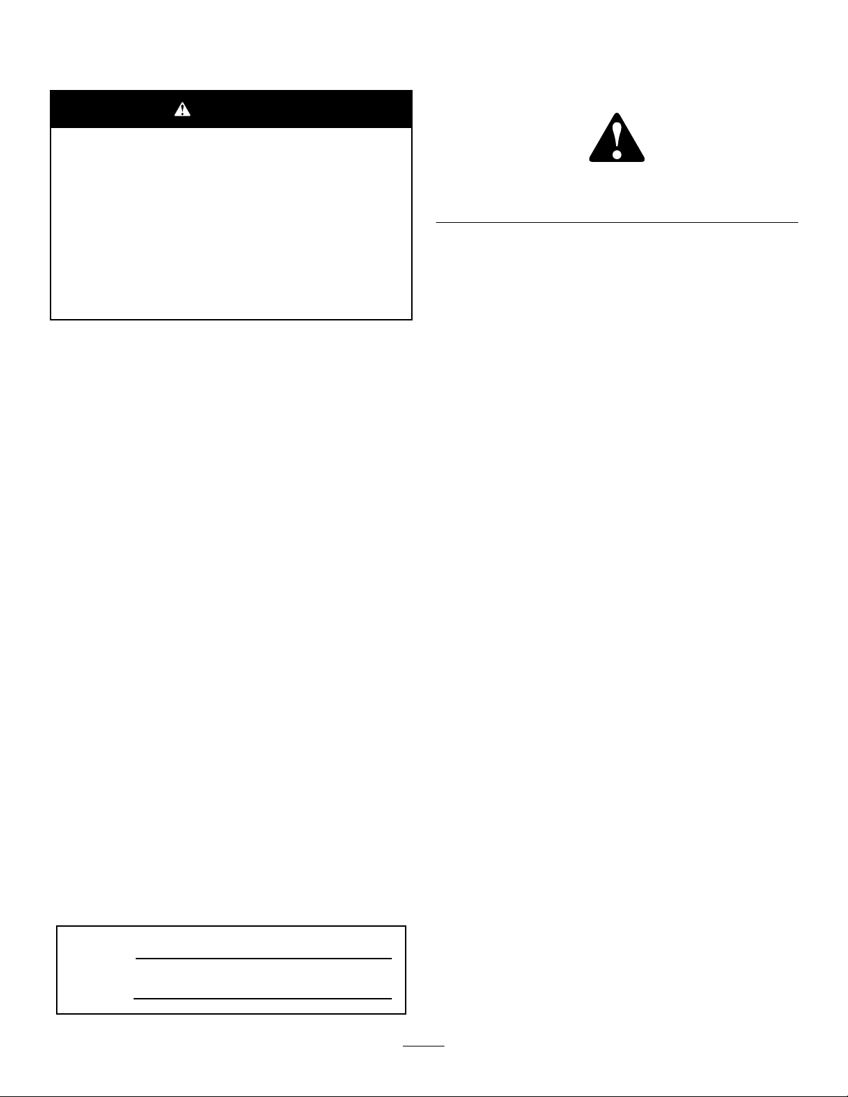
Safetydecalsandinstructionsareeasilyvisibletotheoperatorandarelocatednearanyareaofpotential
danger.Replaceanydecalthatisdamagedorlost.
93-7272
1.Cutting/dismembermenthazard;fan—stayawayfrom
movingparts.
93–6696
1.Storedenergyhazard—readtheOperator'sManual.
106-6754
1.Warning—donottouchthehotsurface.
2.Cutting/dismembermenthazard,fanandentanglement
hazard,belt—stayawayfrommovingparts.
7
Page 8
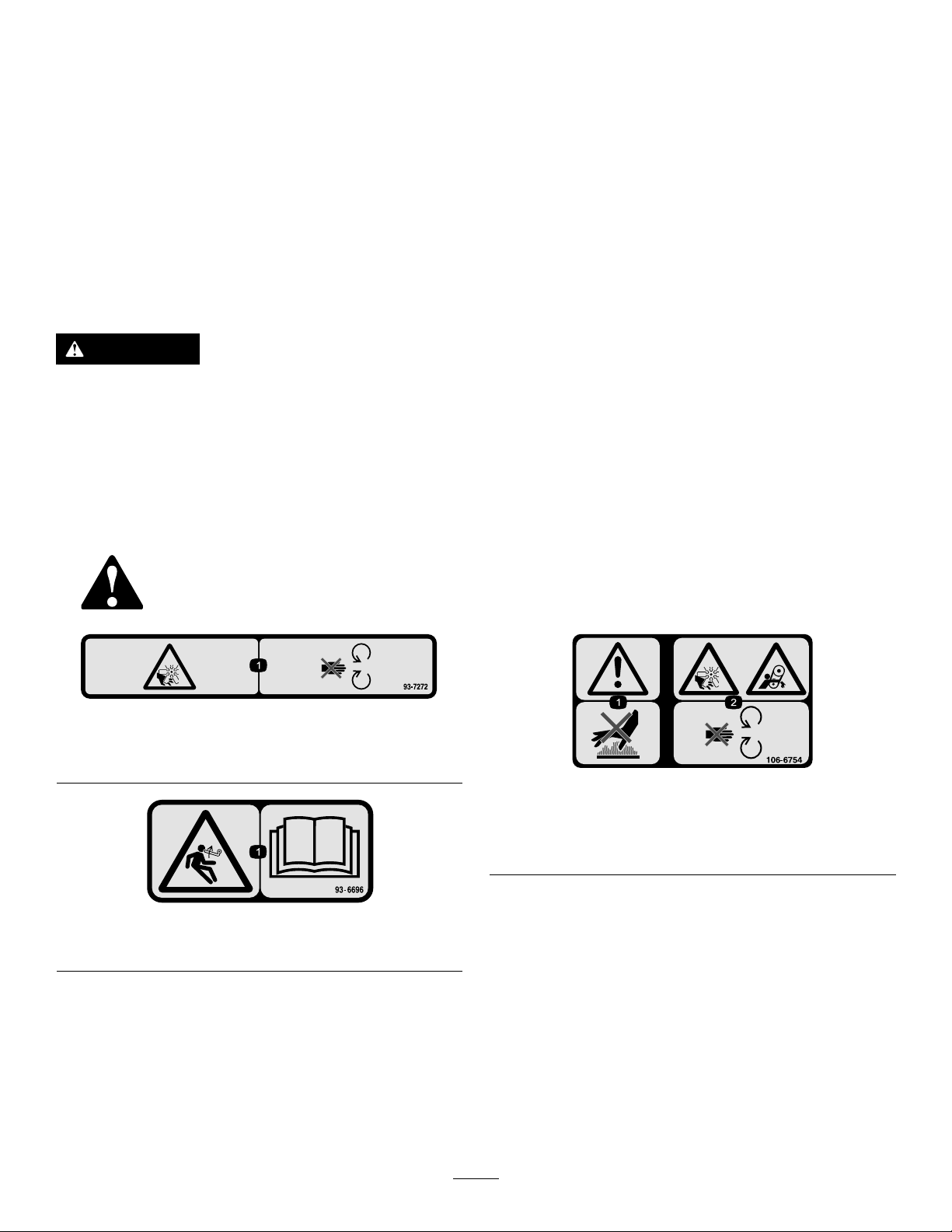
110-0986
106-6755
1.Pressthebrakepedalandparkingbrakepedaltosetthe
parkingbrake.
2.Pressthebrakepedaltoapplythebrake.
3.Pressthetractionpedaltomovethemachineforward.
4.Reelenabledmode
5.Transportmode
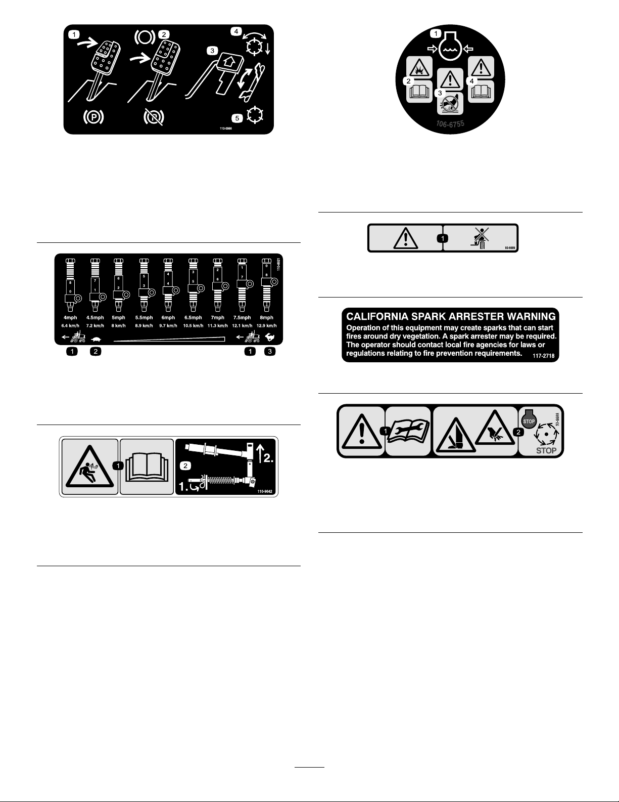
110-8921
1.Tractionunitspeed
2.Slow
3.Fast
1.Enginecoolantunder
pressure.
2.Explosionhazard—read
theOperator'sManual.
1.Warning—donotcarrypassengers.
3.Warning—donottouchthe
hotsurface.
4.Warning—readthe
Operator'sManual.
93-6689
117–2718
110-9642
1.Storedenergyhazard—readtheOperator'sManual.
2.Movethecotterpintotheholeclosesttotherodbracket
andthenremovetheliftarmandpivotyoke.
1.Warning—readthe
instructionsbefore
servicingorperforming
maintenance.
93-6688
2.Cuttinghazardofhandor
foot—stoptheengineand
waitformovingpartsto
stop.
8
Page 9

BatterySymbols
Someorallofthesesymbolsareonyourbattery .
1.Explosionhazard
2.Nore,opename,or
smoking.
3.Causticliquid/chemical
burnhazard
4.Weareyeprotection9.Flusheyesimmediately
5.ReadtheOperator's
Manual.
6.Keepbystandersasafe
distancefromthebattery.
7.Weareyeprotection;
explosivegasescan
causeblindnessandother
injuries.
8.Batteryacidcancause
blindnessorsevereburns.
withwaterandgetmedical
helpfast.
10.Containslead;donot
discard.
1.ReadtheOperator’s
Manual.
2.Engine—start4.Engine—stop
120–4158
3.Engine—preheat
121–5644
1.Lightswitch
2.Engage7.Lower
3.Powertake-off
4.Disengage
5.Fast
117–0169
1.ReadtheOperator'sManual.
2.Powerpoint—10A
3.Headlights—10A
4.Power—10A
5.Enginestart—15A
6.Optionalairrideseatsuspension—10A
7.EnginecomputermanagementC—10A
8.EnginecomputermanagementB—10A
9.EnginecomputermanagementA—10A
6.Slow
8.Raise
9.ReadtheOperator’s
Manual.
9
Page 10

133-2930
1.Warning—readtheOperator'sManual;donotoperatethis
machineunlessyouaretrained.
2.Warning—wearhearingprotection.5.Warning—donotparkonslopes;locktheparkingbrake,stop
3.Thrownobjecthazard—keepbystandersasafedistance
awayfromthemachine.
4.Tippinghazard—slowthemachinebeforeturning;donotturn
athighspeeds;onlydriveonslopeswiththecuttingunits
lowered;alwayswearaseatbelt.
theengineandremovetheignitionkeybeforeleavingthe
machine.
6.Warning—readtheOperator'sManual;donottowthe
machine.
133-2931
1.Warning—readtheOperator'sManual;donotoperatethis
machineunlessyouaretrained.
2.Warning—wearhearingprotection.5.Warning—donotparkonslopes;locktheparkingbrake,stop
3.Thrownobjecthazard—keepbystandersasafedistance
awayfromthemachine
4.Tippinghazard—donotdriveacrossordownslopesgreater
than15degrees;onlydriveonslopeswiththecuttingunits
lowered;alwayswearaseatbelt
theengineandremovetheignitionkeybeforeleavingthe
machine.
6.Warning—readtheOperator'sManual;donottowthe
machine.
10
Page 11
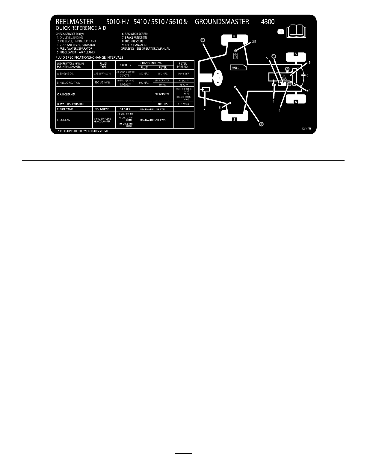
1.ReadtheOperator'sManualformoremaintenanceinformation.
125-8753
11
Page 12

Setup
LooseParts
Usethechartbelowtoverifythatallpartshavebeenshipped.
ProcedureDescription
1
2
3
4
5
6
7
MediaandAdditionalParts
Description
Operator'sManual
Nopartsrequired
Nopartsrequired
Right,fronthoseguide
Left,fronthoseguide
Nopartsrequired
Rearweights(sizevarieswith
conguration).
Hoodlatchassembly1
Washer1
Cutting-unitkickstand
Qty.
1
ReadtheOperator'sManualbeforeoperatingthemachine.
Qty.
–
–
1
1
–
Varies
1Installthecutting-unitkickstand.
Adjustthetirepressure.
Adjustthecontrol-armposition.
Installthecuttingunits.
Adjusttheturf-compensationspring.
Installrearweights(orderfromyour
ToroDistributor).
InstalltheCEhoodlatch.
Use
Use
Engineowner’smanual1
PartsCatalog
DeclarationofConformity
OperatorTrainingMaterial
Note:Determinetheleftandrightsidesofthemachine
fromthenormaloperatingposition.
1
AdjustingtheTirePressure
NoPartsRequired
Procedure
Thetiresareover-inatedforshipping.Therefore,release
someoftheairtoreducethepressure.Correctairpressurein
thefrontandreartiresis83to103kPa(12to15psi).
Engineinformation
1
1
1
Usetoreferencepartnumbers
Declarationofconformity
Reviewbeforeoperatingthemachine
2
AdjustingtheControl-Arm Position
NoPartsRequired
Procedure
Thecontrol-armpositioncanbeadjustedforyourcomfort.
1.Loosenthe2boltssecuringthecontrolarmtothe
retainingbracket(Figure2).
Important:Maintainevenpressureinalltirestoensure
uniformcontactwiththeturf.
12
Page 13
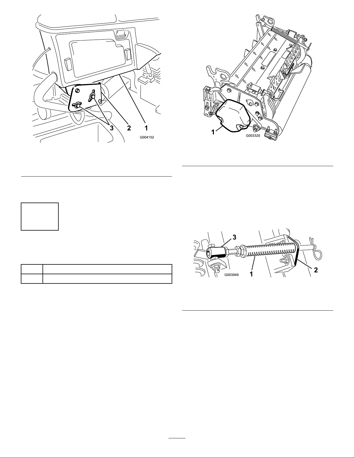
Figure2
1.Controlarm3.Bolts(2)
2.Retainingbrackets
2.Rotatethecontrolarmtothedesiredpositionand
tightenthe2bolts.
3
InstallingtheCuttingUnits
Partsneededforthisprocedure:
1
Right,fronthoseguide
1
Left,fronthoseguide
Procedure
1.Removethereelmotorsfromtheshippingbrackets.
2.Removetheshippingbracketsanddiscard.
3.Removethecuttingunitsfromthecartons.Assemble
andadjustasdescribedinthecuttingunitOperator's
Manual.
4.Makesurethatthecounterweight(Figure3)isinstalled
totheproperendofthecuttingunitasdescribedinthe
cuttingunitOperator'sManual.
Figure3
1.Counterweight
5.Allthecuttingunitsareshippedwiththe
turf-compensationspringmountedtotherightsideof
thecuttingunit.Theturf-compensationspringmustbe
mountedtothesamesideofthecuttingunitasthereel
drivemotor.Positiontheturfcompensationasfollows:
A.Removethe2carriageboltsandnutssecuringthe
rodbrackettothecuttingunittabs(Figure4).
Figure4
1.Turf-compensationspring3.Springtube
2.Rodbracket
B.Removetheangenutsecuringthespringtube
bolttothecarrierframetab(Figure4)Remove
theassembly.
C.Mountthespringtubebolttotheoppositetabon
thecarrierframeandsecurewiththeangenut.
Positiontheboltheadtotheoutersideofthetab
asshowninFigure5.
13
Page 14
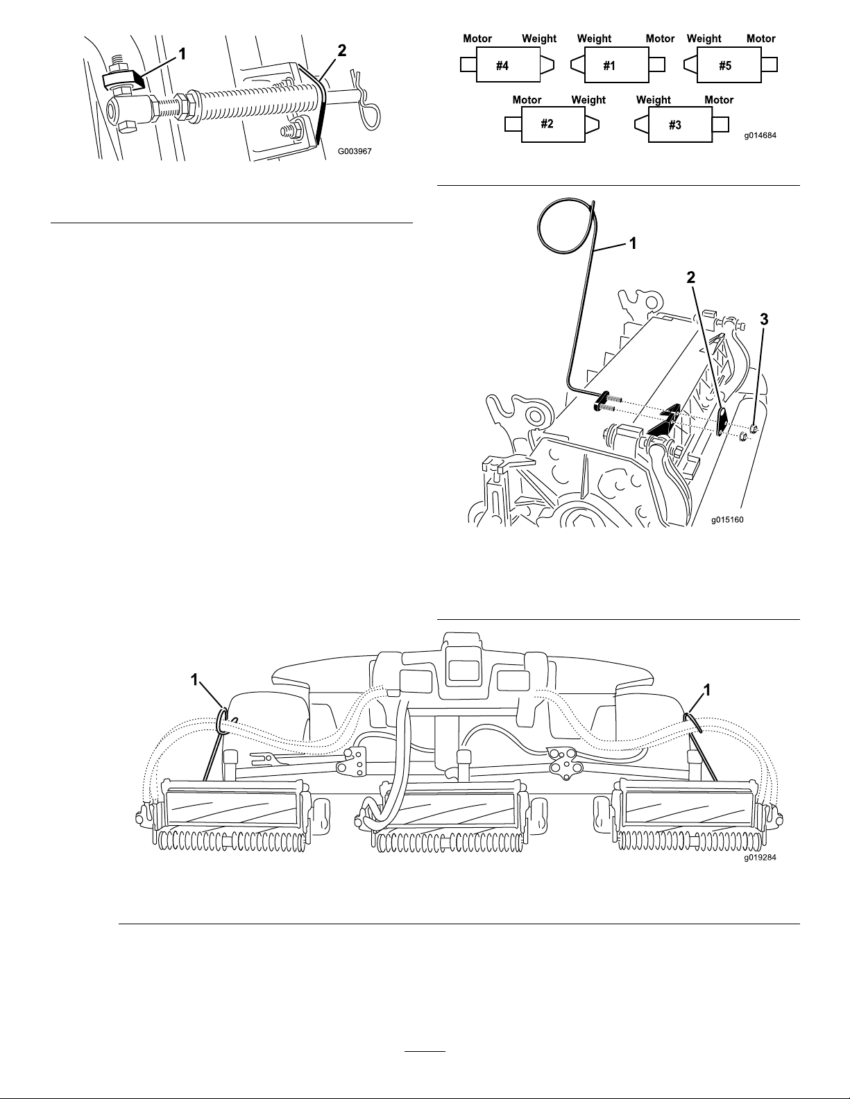
Figure5
g019284
1
1
Figure6
1.Oppositecarrierframetab
2.Rodbracket
D.Mounttherodbrackettothecuttingunittabs
withthecarriageboltsandnuts(Figure5).
Important:Onthe#4(leftfront)and#5
(rightfront)cuttingunits(Figure6),use
therodbracketmountingnutstoinstallthe
hoseguidestothefrontofthecuttingunit
tabs(Figure7).Thehoseguidesshouldlean
towardthecentercuttingunit(Figure7and
Figure8).
Note:Wheninstallingorremovingthecutting
units,makesurethatthehairpincotterisinstalled
inthespringrodholenexttotherodbracket.
Otherwise,thehairpincottermustbeinstalledin
theholeintheendoftherod.
1.Hoseguide(#4cuttingunit
shown)
2.Rodbracket
Figure7
3.Nuts
1.Hoseguides(eachmustleantowardthecentercuttingunit)
Figure8
14
Page 15
6.Loweralltheliftarmscompletely.
7.Removethesnapperpinandthecapfromthe
lift-arm-pivotyoke(Figure9).
Figure9
1.Snapperpin2.Cap
8.Forthefrontcuttingunits,slideacuttingunitunder
theliftarmwhileinsertingthecarrier-frameshaftup
intothelift-arm-pivotyoke(Figure10).
Figure11
1.Lift-arm-pivot-shaftlynchpinandwasher
B.Insertthelift-armyokeontothecarrier-frame
shaft(Figure10).
C.Insertthelift-armshaftintotheliftarmand
secureitwiththewasherandlynchpin(Figure11).
10.Insertthecapoverthecarrier-frameshaftandlift-arm
yoke.
11.Securethecapandthecarrier-frameshafttothe
lift-armyokewiththesnapperpin.
Note:Usetheslotifyoudesireasteeringcuttingunit
orusetheholeifyouarelockingthecuttingunitin
position(Figure9).
12.Securethelift-armchaintothechainbracketwiththe
snapperpin(Figure12).Usethenumberofchainlinks
describedintheOperator'sManualofthecuttingunit.
Figure10
1.Liftarm3.Lift-arm-pivotyoke
2.Carrier-frameshaft
9.Usethefollowingprocedureontherearcuttingunits
whentheheightofcutisabove19mm(3/4inch).
A.Removethelynchpinandwashersecuringthe
lift-arm-pivotshafttotheliftarmandslidethe
lift-arm-pivotshaftoutoftheliftarm(Figure11).
Figure12
1.Lift-armchain2.Chainbracket
13.Onthe#4(leftfront)and#5(rightfront)cutting
units,insertthereelmotorhosesintotherespective
hoseguide.
14.Coatthesplineshaftofthereelmotorwithclean
grease.
15.OilthereelmotorO-ringandinstallitontothemotor
ange.
16.Installthemotorbyrotatingitclockwisesothatthe
motorangesclearthebolts(Figure13).Rotatethe
motorcounterclockwiseuntiltheangesencirclethe
bolts,thentightenthebolts.
Important:Makesurethatthereelmotorhoses
arenottwisted,kinked,orintheriskofbeing
pinched.
15
Page 16

Figure13
1.Reeldrivemotor2.Mountingbolts
4
Adjustingthe Turf-CompensationSpring
NoPartsRequired
Procedure
Theturf-compensationspring(Figure14)transfersweight
fromthefronttotherearroller.Thishelpstoreduceawave
patternintheturf,alsoknownasmarcellingorbobbing.
Figure14
1.Turf-compensationspring3.Springrod
2.Hairpincotter4.Hexnuts
2.Tightenthehexnutsonthefrontendofthespringrod
untilthecompressedlengthofthespringis15.9cm
(6.25inches)(Figure14).
Note:Whenoperatingonroughterrain,decreasethe
springlengthby13mm(1/2inch).Groundfollowing
willbeslightlydecreased.
Important:Makespringadjustmentswiththecutting
unitmountedtothetractionunit,pointingstraight
aheadandloweredtotheshopoor.
1.Makesurethatthehairpincotterisinstalledintherear
holeinthespringrod(Figure14).
16
Page 17

5
InstallingRearWeights
Partsneededforthisprocedure:
Varies
Rearweights(sizevarieswithconguration).
Procedure
ThismachinecomplieswithENISO5395:2013andANSIB71.4-2012Standardswhenequippedwithrearweightsand/or
90lbofcalciumchlorideballastisaddedtorearwheels.Usethefollowingchartstodeterminethecombinationsofweights
requiredforyourconguration.OrderpartsfromyourlocalAuthorizedToroDistributor.
WeightP/N110-8985-03
Groomers,roller
brushes,and/or
baskets
No00
Yes44
Important:Alwaysinstalltubesinsidethereartiresbeforecalciumchlorideisinstalled.Ifapunctureoccursina
tirewithcalciumchloride,removethemachinefromtheturfareaasquicklyaspossible.Topreventpossibledamage
totheturf,immediatelysoaktheaffectedareawithwater.
Usethefollowingproceduretomounttheappropriateamountofweight(seeweightcharts)tothetoporbottomofthe
rearbumperasshowninFigure15.
Numberofweights
tomeetANSI(US)
standards
Numberofweightsto
meetCE(European)
standards
Fasteners(2each
required)forweights
N/AN/A
3231-7CarriageBolt,
104-8301Nut
WeightLocation
1ontopofbumperand
3underbumper
Figure15
1.Tractionmanifold5.Weight(s)
2.Spacers6.Carriagebolt
3.Bolts7.Nut
4.Washers
1.Removethe3bolts,washers,andspacerssecuringthetractionmanifoldtothebottomoftherearbumper(Figure15a).
2.Positiontheappropriateamountofweightonthetopand/orbottomoftherearbumper.
17
Page 18

3.Mounttheweight(s)andthetractionmanifoldtothebumperwiththe3bolts,washersandspacerspreviouslyremoved
(Figure15b).
Note:Donotusethespacerswheninstallingmorethantwoweightsunderthebumper(Figure15c).
4.Securetheouteredgesoftheweight(s)tothebumperwith2carriageboltsandnuts(Figure15c).
6
InstallingtheCEHoodLatch
Partsneededforthisprocedure:
1Hoodlatchassembly
1Washer
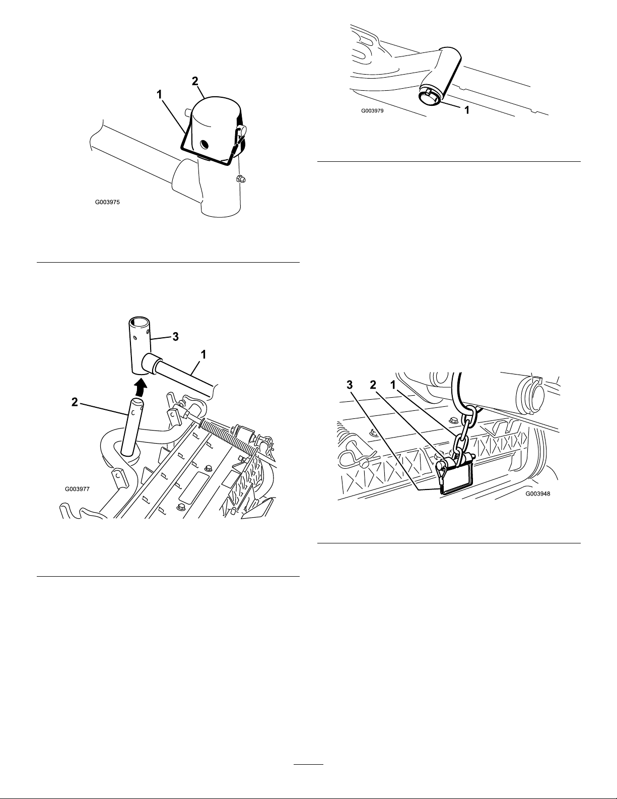
1.Hoodlatch3.Rubberwasher
2.Nut4.Metalwasher
Procedure
Figure17
1.Unlatchandraisethehood.
2.Removetherubbergrommetfromtheholeintheleft
sideofthehood(Figure16).
Figure16
1.Rubbergrommet
4.Outsidethehood,insertthehookendofthelatch
throughtheholeinthehood.
Note:Makesurethattherubbersealingwasher
remainstotheoutersideofthehood.
5.Insidethehood,insertthemetalwasherontothelatch
andsecurewiththenut.
Note:Makesurethatthelatchengagestheframe
catchwhenitislocked.Usetheenclosedhoodlatch
keytooperatethehoodlatch.
7
UsingtheCutting-Unit Kickstand
Partsneededforthisprocedure:
1
Cutting-unitkickstand
3.Removethenutfromthehood-latchassembly(Figure
17).
Procedure
Wheneveryoumusttipthecuttingunittoexposethe
bedknife/reel,propuptherearofthecuttingunitwiththe
kickstandtoensurethatthenutsonthebackendofthe
bedbaradjustingscrewsarenotrestingontheworksurface
(Figure18).
18
Page 19

Figure18
1.Cutting-unitkickstand
Securethekickstandtothechainbracketwiththesnapper
pin(Figure19).
ProductOverview
Controls
Seat-AdjustingKnobs
Theseat-adjustinglever(Figure20)allowsyoutoadjustthe
seatforwardandrearward.Theweightadjustingknobadjusts
theseatforyourweight.Theweightgaugeindicateswhen
theseatisadjustedtoyourweight.Theheight-adjustingknob
adjuststheseatforyourheight.
Figure20
Figure19
1.Chainbracket3.Cutting-unitkickstand
2.Snapperpin
1.Weightgauge3.Height-adjustingknob
2.Weight-adjustingknob
4.Adjustinglever(forward
andrearward)
TractionPedal
Thetractionpedal(Figure21)controlstheforwardand
reverseoperation.Pressthetopofthepedaltomoveforward
andthebottomtomoverearward.Groundspeeddependson
howfaryoupressthepedal.Fornoload,maximumground
speed,fullypressthepedalwhilethethrottleisintheFAST
position.
Tostop,reducefootpressureonthetractionpedalandallow
ittoreturntothecenterposition.
Mow-SpeedLimiter
Whenthemow-speedlimiter(Figure21)isippedup,it
controlsthemowspeedandallowsthecuttingunitstobe
engaged.Eachspaceradjuststhemowingspeedby½mile
perhour.Themorespacersyouhaveonthetopofthebolt,
thesloweryouwillgo.Fortransport,ipbackthemow-speed
limiterandyouwillhavemaximumtransportspeed.
BrakePedal
Pressthebrakepedal(Figure21)tostopthemachine.
ParkingBrake
Toengagetheparkingbrake,(Figure21)pushdownthe
brakepedalandpressthetopforwardtolatch.Toreleasethe
19
Page 20

parkingbrake,pressthebrakepedaluntiltheparkingbrake
1
g021209
latchretracts.
Figure21
1.Tractionpedal4.Brakepedal
2.Mow-speedlimiter5.Parkingbrake
3.Spacers
6.Tilt-steeringpedal
KeySwitch
Thekeyswitch(Figure22)has3positions:OFF,
ON/PREHEAT,andSTART.
LowerMow/RaiseControlLever
Thislever(Figure22)raisesandlowersthecuttingunitsand
alsostartsandstopsthecutterheadswhenthecutterheads
areenabledinthemowmode.
HeadlightSwitch
Pivottheswitchdownwardtoturnontheheadlights(Figure
22).
Enable/DisableSwitch
Usetheenable/disableswitch(Figure22)inconjunctionwith
thelowermow/raisecontrollevertooperatethecutterheads.
Thecutterheadscannotbeloweredwhenthemow/transport
leverisintheTRANSPORTposition.
BacklapLevers
Tilt-SteeringPedal
Totiltthesteeringwheeltowardyou,pressthefootpedal
(Figure21)down,andpullthesteeringtowertowardyouto
themostcomfortablepositionandthenreleasethepedal.
ThrottleControl
Movethethrottlecontrol(Figure22)forwardtoincreasethe
enginespeedandrearwardtodecreasespeed.
Figure22
Usethebacklapleversinconjunctionwiththelower
mow/raisecontrolleverforbacklappingthereels(Figure23).
Figure23
1.Backlaplevers
1.Lowermow/raisecontrol
lever
2.Keyswitch5.Throttlecontrol
3.InfoCenter
4.Enable/disableswitch
6.Headlightswitch
20
Page 21

HydraulicFilterRestrictionIndicator
1
g020650
2
3
4
TORO
UsingtheInfoCenterLCDDisplay
Withtheenginerunningatnormaloperatingtemperature,
viewtheindicator(Figure24);itshouldbeintheGreenzone.
WhentheindicatorisintheRedzone,changethehydraulic
lters.
Figure24
1.Hydrauliclterrestrictionindicator
PowerPoint
Thepowerpointisa12Vpowersupplyforelectronicdevices
(Figure25).
TheInfoCenterLCDdisplayshowsinformationaboutyour
machinesuchastheoperatingstatus,variousdiagnostics
andotherinformationaboutthemachine(Figure26)There
isasplashscreenandmaininformationscreenofthe
InfoCenter.Youcanswitchbetweenthesplashscreenand
maininformationscreen,atanytime,bypressinganyof
theInfoCenterbuttonsandthenselectingtheappropriate
directionalarrow .
Figure26
1.Indicatorlight3.Middlebutton
2.Rightbutton
4.Leftbutton
•LeftButton,MenuAccess/BackButton—pressthis
buttontoaccesstheInfoCentermenus.Youcanuseitto
backoutofanymenuyouarecurrentlyusing.
•MiddleButton—usethisbuttontoscrolldownmenus.
•RightButton—usethisbuttontoopenamenuwherea
rightarrowindicatesadditionalcontent.
Note:Thepurposeofeachbuttonmaychangedepending
onwhatisrequiredatthetime.Eachbuttonislabeledwith
anicondisplayingitscurrentfunction.
InfoCenterIconDescription
SERVICEDUE
Figure25
1.Powerpoint
Indicateswhenscheduledservice
shouldbeperformed
Hourmeter
Infoicon
Fast
Slow
Fuellevel
21
Page 22

InfoCenterIconDescription(cont'd.)
InfoCenterIconDescription(cont'd.)
Glowplugsareactive
Raisecuttingunits
Lowercuttingunits
Operatormustsitinseat
ParkingBrakeIndicator—indicates
whentheparkingbrakeisOn
IdentiestherangeasHigh
(Transport)
Neutral
IdentiestherangeasLow(Mow)
CoolantTemperature-indicatesthe
enginecoolanttemperatureineither
°Cor°F
Temperature(hot)
Bulb
OutputofTECcontrollerorcontrol
wireinharness
Switch
Operatormustreleaseswitch
Operatorshouldchangetoindicated
state
Symbolsareoften
combinedtoform
sentences.Some
examplesareshown
below
Operatorshouldputmachinein
neutral
Enginestartdenied
Engineshutdown
Enginecoolanttoohot
PTOisengaged
Deniedornotallowed
EngineStart
Stoporshutdown
Engine
Keyswitch
Indicateswhenthecuttingunitsare
beinglowered
Indicateswhenthecuttingunitsare
beingraised
PINpasscode
CANbus
InfoCenter
Sitdownorsetparkingbrake
UsingtheMenus
ToaccesstheInfoCentermenusystem,pressthemenuaccess
buttonwhileatthemainscreen.Thisbringsyoutothemain
menu.Refertothefollowingtablesforasynopsisofthe
optionsavailablefromthemenus:
MainMenu
MenuItemDescription
FaultsTheFaultsmenucontains
alistoftherecentmachine
faults.RefertotheService
ManualoryourAuthorized
ToroDistributorformore
informationontheFaults
menuandtheinformation
containedthere.
ServiceTheServicemenucontains
informationonthemachine
suchashoursofuse,counters,
andothersimilarnumbers.
Badorfailed
22
Page 23

DiagnosticsTheDiagnosticsmenu
SettingsTheSettingsmenuallows
AboutTheAboutmenuliststhe
Service
MenuItemDescription
Hours
Counts
Diagnostics
MenuItemDescription
CuttingUnitsIndicatestheinputs,qualiers,
Hi/LowRangeIndicatestheinputs,qualiers,
PTOIndicatestheinputs,qualiers,
EngineRun
Backlap
displaysthestateofeach
machineswitch,sensor,and
controloutput.Y oucanuse
thistotroubleshootcertain
issuesasitwillquicklytellyou
whichmachinecontrolsareon
andwhichareoff.
youtocustomizeandmodify
congurationvariablesonthe
InfoCenterdisplay.
modelnumber,serialnumber,
andsoftwareversionofyour
machine.
Liststhetotalnumberofhours
thatthemachine,engineand
PTOhavebeenon,aswell
asthenumberofhoursthe
machinehasbeentransported
andservicedue.
Listsnumerouscountsthe
machinehasexperienced.
andoutputsforraisingand
loweringthecuttingunits.
andoutputsfordrivingin
transportmode.
andoutputsforenablingthe
PTOcircuit.
Indicatestheinputs,qualiers,
andoutputsforstartingthe
engine.
Indicatestheinputs,qualiers
andoutputsforoperatingthe
backlapfunction.
FrontBacklapReelSpeedControlsthespeedofthefront
RearBacklapReelSpeedControlsthespeedoftherear
ProtectedMenusAllowsthe
BladeCountControlsthenumberofblades
MowSpeedControlsthegroundspeedfor
Heightofcut(HOC)Controlstheheightofcut
FReelRPMDisplaysthecalculatedreel
RReelRPMDisplaysthecalculatedreel
reelsinbacklapmode.
reelsinbacklapmode.
superintendant/mechanic
toaccessprotectedmenusby
inputtingapasscode.
onthereelforreelspeed.
determiningthereelspeed.
(HOC)fordeterminingthereel
speed.
speedpositionforthefront
reels.Thereelscanalsobe
manuallyadjusted.
speedpositionfortherear
reels.Thereelscanalsobe
manuallyadjusted.
*Only"operator-faced"textistranslated.Faults,Service,and
Diagnosticsscreensare"service-faced".Titlesarebeinthe
selectedlanguage,butmenuitemsareinEnglish.
About
MenuItemDescription
Model
SNListstheserialnumberofthe
MachineControllerRevisionListsthesoftwarerevisionof
InfoCenterRevisionListsthesoftwarerevisionof
CANBus
Liststhemodelnumberofthe
machine.
machine.
themastercontroller .
theInfoCenter.
Liststhemachine
communicationbusstatus.
ProtectedMenus
Settings
MenuItemDescription
Units
Language
LCDBacklightControlsthebrightnessofthe
LCDContrastControlsthecontrastofthe
Controlstheunitsusedonthe
InfoCenter.Themenuchoices
areEnglishorMetric
Controlsthelanguageused
ontheInfoCenter*.
LCDdisplay.
LCDdisplay.
Thereare5operatingcongurationsettingsthatareadjustable
withintheSettingsMenuoftheInfoCenter:BladeCount,
MowSpeed,HeightofCut(HOC),FReelRPMandRReel
RPM.ThesesettingscanbelockedbyusingtheProtected
Menu.
Note:Atthetimeofdelivery,theinitialpasswordcodeis
programmedbyyourdistributor.
AccessingtheProtectedMenuSettings
ToaccesstheProtectedMenuSettings
•FromtheMainMenu,scrolldowntotheSettingsMenu
andpresstherightbutton.
23
Page 24

•IntheSettingsMenu,scrolldowntotheProtectedMenu
andpresstherightbutton.
•Toenterthepasscode,usethecenterbuttontosetthe
rstdigitthenpresstherightbuttontomoveontothe
nextdigit.
•Usethecenterbuttontosettheseconddigitthenpress
therightbuttontomoveontothenextdigit.
•Usethecenterbuttontosetthethirddigitthenpressthe
rightbuttontomoveontothenextdigit.
•Usethecenterbuttontosetthefourthdigitthenpress
therightbutton.
•Pressthemiddlebuttontoenterthecode.
•Ifthecodehasbeenacceptedandtheprotectedmenuhas
been“Unlocked,”“PIN”willbedisplayedintheupper
rightcornerofthedisplayscreen.
TheabilitytoviewandchangethesettingsintheProtected
Menucanbechanged.OnceyouhaveaccessedtheProtected
Menu,scrolldowntoProtectSettings.Usingtherightbutton,
changingProtectSettingstoOffallowsyoutoviewand
changethesettingsintheProtectedMenuwithoutentering
thepasscode.ChangingProtectSettingstoOnhidesthe
protectedoptionsandrequiresenteringapasscodetochange
thesettingintheProtectedMenu.Afterthepasscodehas
beenset,thekeyswitchmustbeturnedoffandbackonto
enableandsavethisfeature.
Note:Ifthepasscodehasbeenforgottenormisplaced,
pleasecontactyourdistributorforassistance.
ToSettheMowSpeed
•IntheSettingsMenu,scrolldowntoMowSpeed.
•Presstherightbuttontoselectmowspeed.
•Usethecenterandrightbuttontoselecttheappropriate
mowspeedsetonthemechanicalmow-speedlimiteron
thetractionpedal.
•Presstheleftbuttontoexitmowspeedandsavethe
setting.
ToSettheHeightofCut(HOC)
•IntheSettingsMenu,scrolldowntoHOC.
•PresstherightbuttontoselectHOC.
•Usethecenterandrightbuttontoselecttheappropriate
HOCsetting.(Iftheexactsettingisnotdisplayed,select
thenearestHOCsettingfromthelistdisplayed).
•PresstheleftbuttontoexitHOCandsavethesetting.
ToSettheFrontandRearReelSpeeds
Althoughthefrontandrearreelspeedsarecalculatedby
inputtingthenumberofblades,mowspeedandHOCinto
theInfoCenter,thesettingcanbemanuallychangedto
accommodatefordifferentmowingconditions.
•TochangetheReelSpeedSettings,scrolldowntotheF
ReelRPM,RReelRPMorboth.
ToSettheBladeCount
•IntheSettingsMenu,scrolldowntoBladeCount
•Presstherightbuttontochangethebladecountbetween
5,8or11bladereels.
Specications
Note:Specicationsanddesignaresubjecttochange
withoutnotice.
Specication
TransportWidth
Widthofcut254cm(100inches)
Length
Height
Weight
Engine
Fueltankcapacity
233cm(92inches)
282cm(111inches)
160cm(63inches)
1,276kg(2,813lb)
Kubota44.2hp(Turbo)
53L(14USgallons)
•Presstherightbuttontochangethereelspeedvalue.As
thespeedsettingischanged,thedisplaywillcontinueto
showthecalculatedreelspeedbasedonbladecount,
mowspeedandHOCwhichwaspreviouslyentered,but
thenewvaluewillalsobedisplayed.
Attachments/Accessories
AselectionofToroapprovedattachmentsandaccessoriesis
availableforusewiththemachinetoenhanceandexpand
itscapabilities.ContactyourAuthorizedServiceDealeror
Distributororgotowww .Toro.comforalistofallapproved
attachmentsandaccessories.
Transportspeed
Mowingspeed
0to16km/h(0to10mph)
0to13km/h(0to8mph)
24
Page 25

Operation
Note:Determinetheleftandrightsidesofthemachine
fromthenormaloperatingposition.
CAUTION
Ifyouleavethekeyintheignitionswitch,someone
couldaccidentlystarttheengineandseriously
injureyouorotherbystanders.
Lowerthecuttingunitstotheground,setthe
parkingbrakeandremovethekeyfromtheignition
switchbeforeservicingormakingadjustmentsto
themachine.
CheckingtheEngine-OilLevel
Theengineisshippedwithoilinthecrankcase;however,
checktheoillevelbeforeandafteryourststarttheengine.
Crankcasecapacityisapproximately5.2L(5.5USqt)with
thelter.
Usehigh-qualityengineoilthatmeetsthefollowing
specications:
•APIClassicationLevelRequired:CH-4,CI-4orhigher
•Preferredoil:SAE15W-40(above0degreesF)
•Alternateoil:SAE10W-30or5W-30(alltemperatures)
ToroPremiumEngineoilisavailablefromyourdistributorin
either15W -40or10W-30viscosity.
1.Parkthemachineonalevelsurface,shutofftheengine,
settheparkingbrake,andremovethekeyfromthe
ignitionswitch.
2.Openthehood.
3.Removethedipstick,wipeitclean,andinstallit(Figure
27).
Figure27
1.Dipstick
4.Removethedipstickandchecktheoillevelonthe
dipstick.
Note:TheoillevelshouldbeuptotheFullmark.
5.IftheoillevelisbelowtheFullmark,removethell
cap(Figure28),andaddoiluntilthelevelreachesthe
Fullmarkondipstick.
1.Oil-llcap
Important:Donotoverll.Besuretokeepthe
engine-oillevelbetweentheupperandlowerlimits
ontheoilgauge.Enginefailuremayoccurasa
resultofoverllingorunderllingtheengineoil.
6.Installtheoil-llcapandclosethehood.
25
Figure28
Page 26

CheckingtheCoolingSystem
AddingFuel
Cleandebrisoffthescreen,oilcooler,andfrontofthe
radiatordailyandmoreoftenifconditionsareextremelydusty
anddirty.RefertothesectiononRemovingDebrisfromthe
CoolingSysteminCoolingSystemMaintenance(page43).
Thecoolingsystemislledwitha50/50solutionofwater
andpermanentethyleneglycolantifreeze.Checkthelevelof
coolantintheexpansiontankatthebeginningofeachday
beforestartingtheengine.Thecapacityofthecoolingsystem
is9.5L(10.0USqt).
CAUTION
Iftheenginehasbeenrunning,thepressurized,hot
coolantcanescapeandcauseburns.
•Donotopentheradiatorcapwhentheengine
isrunning.
•Usearagwhenopeningtheradiatorcap,and
openthecapslowlytoallowsteamtoescape.
1.Checkthelevelofcoolantintheexpansiontank
(Figure29).
Note:Thecoolantlevelshouldbebetweenthemarks
onthesideofthetank.
Useonlyclean,freshdieselfuelorbiodieselfuelswithlow
(<500ppm)orultralow(<15ppm)sulfurcontent.The
minimumcetaneratingshouldbe40.Purchasefuelin
quantitiesthatcanbeusedwithin180daystoensurefuel
freshness.
Fueltankcapacity:53L(14USgallons)
Usesummergradedieselfuel(No.2-D)attemperatures
above-7°C(20°F)andwintergrade(No.1-DorNo.
1-D/2-Dblend)belowthattemperature.Usingwinter-grade
fuelatlowertemperaturesprovideslowerashpointand
coldowcharacteristicswhicheasesstartingandreducesfuel
lterplugging.
Usingsummer-gradefuelabove-7°C(20°F)contributes
towardlongerfuelpumplifeandincreasedpowercompared
towinter-gradefuel.
Important:Donotusekeroseneorgasolineinsteadof
dieselfuel.Failuretoobservethiscautionwilldamage
theengine.
WARNING
Fuelisharmfulorfatalifswallowed.Long-term
exposuretovaporscancauseseriousinjuryand
illness.
Figure29
1.Expansiontank
2.Ifthecoolantlevelislow,removetheexpansion-tank
capandreplenishthesystem.
Important:Donotoverll.
3.Installtheexpansion-tankcap.
•Avoidprolongedbreathingofvapors.
•Keepfaceawayfromnozzleandgastankor
conditioneropening.
•Keepfuelawayfromeyesandskin.
BiodieselReady
Thismachinecanalsouseabiodieselblendedfuelofup
toB20(20%biodiesel,80%petrodiesel).Thepetrodiesel
portionshouldbeloworultralowsulfur.Observethe
followingprecautions:
•Thebiodieselportionofthefuelmustmeetspecication
ASTMD6751orEN14214.
•TheblendedfuelcompositionshouldmeetASTMD975
orEN590.
•Paintedsurfacesmaybedamagedbybiodieselblends.
•UseB5(biodieselcontentof5%)orlesserblendsincold
weather.
•Monitorseals,hoses,gasketsincontactwithfuelasthey
maydegradeovertime.
•Fuellterpluggingmaybeexpectedforatimeafter
convertingtobiodieselblended.
•Contactyourdistributorifyouwishformoreinformation
onbiodiesel.
26
Page 27

DANGER
1
G021210
Incertainconditions,fuelisextremelyammable
andhighlyexplosive.Areorexplosionfromfuel
canburnyouandothersandcandamageproperty.
•Fillthefueltankoutdoors,inanopenarea,when
theengineiscold.Wipeupanyfuelthatspills.
•Neverllthefueltankinsideanenclosedtrailer.
•Neversmokewhenhandlingfuel,andstayaway
fromanopenameorwherefuelfumesmaybe
ignitedbyaspark.
•Storefuelinanapprovedcontainerandkeepit
outofthereachofchildren.Neverbuymore
thana30-daysupplyoffuel.
•Donotoperatewithoutentireexhaustsystemin
placeandinproperworkingcondition.
DANGER
Incertainconditionsduringfueling,static
electricitycanbereleased,causingasparkwhich
canignitethefuelvapors.Areorexplosionfrom
fuelcanburnyouandothersandcandamage
property.
•Alwaysplacefuelcontainersonthegroundaway
fromyourvehiclebeforelling.
•Donotllfuelcontainersinsideavehicleoron
atruckortrailerbedbecauseinteriorcarpets
orplastictruckbedlinersmayinsulatethe
containerandslowthelossofanystaticcharge.
•Whenpractical,removeequipmentfromthe
truckortrailerandrefueltheequipmentwithits
wheelsontheground.
•Ifthisisnotpossible,thenrefuelsuchequipment
onatruckortrailerfromaportablecontainer,
ratherthanfromafuel-dispensernozzle.
•Ifyoumustuseafuel-dispensernozzle,keepthe
nozzleincontactwiththerimofthefueltank
orcontaineropeningatalltimesuntilfuelingis
complete.
1.Parkthemachineonalevelsurface.
2.Usingacleanrag,cleantheareaaroundthefuel-tank
cap.
3.Removethecapfromthefueltank(Figure30).
Figure30
1.Fuel-tankcap
4.Fillthetankwithfueluntilthelevelistothebottomof
thellerneck.
5.Installthefuel-tankcaptightlyafterllingthetank.
Note:Ifpossible,llthefueltankaftereachuse.This
minimizespossiblebuildupofcondensationinsidethe
fueltank.
CheckingtheHydraulicFluid
Themachinesreservoirislledatthefactorywith
approximately56.7L(15USgallons)ofhighqualityhydraulic
uid.Checkthelevelofthehydraulicuidbeforethe
engineisrststartedanddailythereafter.Therecommended
replacementuidisasfollows:
ToroPremiumAllSeasonHydraulicFluid(Availablein5
gallonpailsor55gallondrums.SeepartscatalogorToro
distributorforpartnumbers.)
Alternateuids:IftheT orouidisnotavailable,other
uidsmaybeusedprovidedtheymeetallthefollowing
materialpropertiesandindustryspecications.Wedonot
recommendtheuseofsyntheticuid.Consultwithyour
lubricantdistributortoidentifyasatisfactoryproductNote:
Torodoesnotassumeresponsibilityfordamagecausedby
impropersubstitutions,souseonlyproductsfromreputable
manufacturerswhowillstandbehindtheirrecommendation.
HighViscosityIndex/LowPourPointAnti-wearHydraulic
Fluid,ISOVG46
MaterialProperties:
Viscosity,ASTMD445cSt@40°C44to48cSt
ViscosityIndexASTM
D2270
PourPoint,ASTMD97-34°Fto-49°F
IndustrySpecications:
VickersI-286-S(QualityLevel),VickersM-2950-S
(QualityLevel),DenisonHF-0
@100°C7.9to8.5
140to160
Important:TheISOVG46Multigradeuidhasbeen
foundtoofferoptimalperformanceinawiderangeof
temperatureconditions.Foroperationinconsistently
27
Page 28

highambienttemperatures,18°C(65°F)to49°C(120°
1
g021215
F),ISOVG68hydraulicuidmayofferimproved
performance.
CheckingtheReel-to-Bedknife Contact
PremiumBiodegradableHydraulicFluid-MobilEAL
EnviroSyn46H
Important:MobilEALEnviroSyn46Histheonly
syntheticbiodegradableuidapprovedbyToro.This
uidiscompatiblewiththeelastomersusedinToro
hydraulicsystemsandissuitableforawide-range
oftemperatureconditions.Thisuidiscompatible
withconventionalmineraloils,butformaximum
biodegradabilityandperformancethehydraulicsystem
shouldbethoroughlyushedofconventionaluid.The
oilisavailablein19L(5gallon)containersor55gallon
drumsfromyourMobilDistributor.
Important:Manyhydraulicuidsarealmostcolorless,
makingitdifculttospotleaks.Areddyeadditivefor
thehydraulicsystemuidisavailablein20ml(2/3
ounces)bottles.Onebottleissufcientfor15to22L
(4to6USgallons)ofhydraulicuid.Orderpartno.
44-2500fromyourauthorizedTorodistributor.
1.Positionthemachineonalevelsurface,lowerthe
cuttingdecks,andshutofftheengine.
2.Cleantheareaaroundthellerneckandcapofthe
hydraulictank(Figure31).
Eachdaybeforeoperating,checkthereel-to-bedknifecontact,
regardlessifthequalityofcuthadpreviouslybeenacceptable.
Theremustbelightcontactacrossthefulllengthofthereel
andthebedknife;refertoAdjustingtheReeltoBedknifein
theOperator'sManualofthecuttingunit.
CheckingtheTorqueofthe WheelNuts
Torquethewheelnutsto94to122N⋅m(70to90ft-lb)
after1to4hoursofoperationandagainafter10hoursof
operation.Torqueevery250hoursthereafter.
WARNING
Failuretomaintainpropertorqueofthewheelnuts
couldresultinpersonalinjury.
Maintainthepropertorqueonthewheelnuts.
BreakingintheMachine
Toensureoptimumperformanceoftheparking-brakesystem,
burnish(breakin)thebrakesbeforeuse.Settheforward
tractionspeedto4mphtomatchthereversetractionspeed.
(All8spacersmovedtothetopofthemow-speedcontrol.)
Withtheengineathighidle,proceedforwardwiththe
mow-speed-controlstopengagedandridethebrakefor15
seconds.Proceedbackwardatfullreversespeedandridethe
brakefor15seconds.Repeatthis5times,waiting1minute
betweeneachforwardandreversecycletoavoidoverheating
thebrakes.Anadjustmenttothebrakesmayberequiredafter
break-in;refertoAdjustingtheParkingBrakes(page44).
Figure31
1.Hydraulictankcap
3.Removethecap/dipstickfromthellerneckandwipe
itwithacleanrag.
4.Insertthedipstickintothellerneck;thenremoveit
andchecklevelofuid.
Note:Theuidlevelshouldbewithintheoperating
rangeonthedipstick.
5.Ifthelevelislow,addappropriateuidtoraiselevelto
theFullmark.
Important:Donotoverll.
6.Installthecap/dipstickontothellerneck.
BleedingtheFuelSystem
Youmustbleedthefuelsystembeforestartingtheengineif
anyofthefollowingsituationshaveoccurred:
•Initialstartupofanewmachine.
•Enginehasceasedrunningduetolackoffuel.
•Maintenancehasbeenperformeduponfuelsystem
components;i.e.,lterreplaced,separatorserviced,etc.
28
Page 29

DANGER
Undercertainconditions,dieselfuelandfuel
vaporsarehighlyammableandexplosive.Are
orexplosionfromfuelcanburnyouandothersand
cancausepropertydamage.
•Useafunnelandllthefueltankoutdoors,in
anopenarea,whentheengineisoffandiscold.
Wipeupanyfuelthatspills.
•Donotllthefueltankcompletelyfull.Add
fueltothefueltankuntilthelevelis6to13mm
(1/4to1/2inch)belowthebottomoftheller
neck.Thisemptyspaceinthetankallowsthe
fueltoexpand.
•Neversmokewhenhandlingfuel,andstayaway
fromanopenameorwherefuelfumesmaybe
ignitedbyaspark.
5.TightenthescrewandturnthekeytotheOFFposition.
Note:Normally,theengineshouldstartaftertheabove
bleedingproceduresarefollowed.However,iftheengine
doesnotstart,airmaybetrappedbetweeninjectionpump
andinjectors;refertoBleedingAirfromtheFuelInjectors
(page41).
StartingandStoppingthe Engine
Important:Y oumustbleedthefuelsystembefore
startingtheengineifyouarestartingtheengineforthe
rsttime,theenginehasstoppedduetolackoffuel,or
youhaveperformedmaintenanceonthefuelsystem;
refertoBleedingtheFuelSystem(page28).
StartingtheEngine
•Storefuelinaclean,safety-approvedcontainer
andkeepthecapinplace.
1.Parkthemachineonalevelsurfaceandensurethatthe
fueltankisatleasthalffull.
2.Openthehood.
3.Opentheair-bleedscrewonthefuel-injectionpump
(Figure32)witha12mmwrench.
1.Sitontheseat,keepyourfootoffthetractionpedalso
thatitisintheNEUTRALposition,engagetheparking
brake,setthethrottletotheFASTposition,andensure
thattheEnable/DisableswitchisintheDISABLE
position.
2.TurntheignitionswitchtotheON/PREHEATposition.
Note:Anautomatictimerwillcontroltheglowplug
preheatfor6seconds.
3.Afterpreheatingtheglowplugs,turnkeytotheSTART
position.
Important:Cranktheenginefornolongerthan15
seconds.Releasethekeywhentheenginestarts.
Ifadditionalpreheatingisrequired,turnkeyto
theOFFpositionandthentotheON/PREHEAT
position.Repeatthisprocessasrequired.
4.Runtheengineatlowidlespeeduntilitwarmsup.
StoppingtheEngine
1.MoveallcontrolstoNEUTRAL,settheparkingbrake,
movethethrottletotheLOWIDLEpositionandallow
theenginetoreachlowidlespeed.
Figure32
1.Bleedscrew
4.TurnthekeyintheignitionswitchtotheONposition.
Note:Theelectricfuelpumpbeginstooperate,
therebyforcingairoutaroundtheair-bleedscrew .
LeavethekeyintheONpositionuntilasolidstream
offuelowsoutaroundthescrew .
Important:Allowtheenginetoidlefor5
minutesbeforeshuttingitoffafterafullload
operation.Failuretodosomayleadtotroubleon
aturbo-chargedengine.
2.TurnthekeytotheOFFpositionandremoveitfrom
theswitch.
29
Page 30

SettingtheReelSpeed
g019276
1
2
Toachieveaconsistent,highqualityofcutandauniform
after-cutappearance,itisimportantthatyousetthereelspeed
tothepropersetting.Adjustthereelspeedasfollows:
1.IntheInfoCenter,underthesettingsmenu,enterthe
bladecount,mowspeedandHOCtocalculatethe
properreelspeed.
2.Iffurtheradjustmentsarerequired,inthesettings
menu,scrolldowntotheFReelRPM,RReelRPM
orboth.
3.Presstherightbuttontochangethereelspeedvalue.
Asthespeedsettingischanged,thedisplaywill
continuetoshowthecalculatedreelspeedbasedon
bladecount,mowspeedandHOC,butthenewvalue
willalsobedisplayed.
Figure33
1.Spring2.Springactuator
3.Repeattheprocedureontheotherspring.
Note:Youmayneedtoincreaseordecreasethereel
speedtocompensateforvaryingturfconditions.
AdjustingtheLiftArm Counterbalance
Youcanadjustthecounterbalanceontherearcuttingunit
liftarmstocompensatefordifferentturfconditionsandto
maintainauniformheight-of-cutintheroughconditionsor
inareasofthatchbuildup.
Youcanadjusteachcounterbalancespringto1of4settings.
Eachincrementincreasesordecreasescounterbalanceonthe
cuttingunitby2.3kg(5lb).Thespringscanbepositionedon
thebacksideoftherstspringactuatortoremoveallcounter
balance(fourthposition).
1.Positionthemachineonalevelsurface,lowerthe
cuttingunits,shutofftheengine,engagetheparking
brakes,andremovethekeyfromignitionswitch.
2.Insertatubeorsimilarobjectontothelongspringend
andpivotitaroundthespringactuatortothedesired
position(Figure33).
AdjustingtheLift-Arm TurnaroundPosition
1.Positionthemachineonalevelsurface,lowerthe
cuttingunits,shutofftheengine,engagetheparking
brakes,andremovethekeyfromignitionswitch.
2.Theliftarmswitchislocatedunderneaththehydraulic
tankbehindthefrontrightliftarm(Figure34).
3.Loosentheswitchmountingscrews(Figure34)
andmovetheswitchdowntoincreasethelift-arm
turnaroundheightormovetheswitchuptodecrease
thelift-armturnaroundheight.Tightenthemounting
screws.
CAUTION
Thespringsareundertension.
Usecautionwhenadjustingthem.
Figure34
1.Switch2.Lift-armsensingdevice
30
Page 31

PushingorTowingthe
JackingPoints
Machine
Inanemergency,themachinecanbemovedbyactuatingthe
bypassvalveinthevariabledisplacementhydraulicpumpand
pushingortowingthemachine.
Important:Donotpushortowthemachinefasterthan
3to4.8km/h(2to3mph)becauseinternaltransmission
damagemayoccur.Thebypassvalvemustbeopen
wheneveryoupushortowthemachine.
1.Thebypassvalveislocatedontheleftsideofthe
hydrostat(Figure35).Rotatethebolt1-1/2turnsto
openandallowuidtobypassinternally.
Note:Youcannowmovethemachineslowlywithout
damagingthetransmission.
Note:Usejackstandstosupportthemachinewhenrequired.
•Front—rectangularpad,undertheaxletube,insideeach
fronttire(Figure36).
Figure36
1.Frontjackingpoint
Figure35
1.Bypassvalve
2.Closethebypassvalvebeforestartingtheengine.
However,donotexceed7to11N∙m.(5to8ft-lb)
torquetoclosethevalve.
Important:Runningtheenginewiththebypass
valveopencausesthetransmissiontooverheat.
•Rear—rectangularaxletubeontherearaxle.
31
Page 32

LocatingtheTieDowns
G031851
g021272
TORO
UnderstandingtheDiagnostic
•Front—theholeintherectangularpad,undertheaxle
tube,insideeachfronttire(Figure37).
Figure37
1.Fronttiedown
Light
Themachineisequippedwithadiagnosticlightwhich
indicatesiftheelectroniccontrollersensesanelectronic
malfunction.Thediagnosticlightislocatedonthecontrol
arm(Figure39).Whenthemachineisfunctioningproperly
andthekeyswitchismovedtotheON/RUNposition,the
diagnosticlightturnsonbrieytoindicatethelightisworking
properly.Whenamachineadvisorymessageisdisplayed,the
lightilluminateswhenthemessageispresent.Whenafault
messageisdisplayed,thelightblinksuntilthefaultisresolved.
•Rear—eachsideofthemachineontherearframe(Figure
38).
Figure38
1.Reartiedown
Figure39
1.Diagnosticlight
CheckingtheInterlock Switches
Thepurposeoftheinterlockswitchesistopreventtheengine
fromcrankingorstartingunlessthetractionpedalisinthe
NEUTRALposition,theEnable/Disableswitchisinthe
DISABLEposition,andtheLowerMow/Raisecontrolisin
theNEUTRALposition.Inaddition,theengineshouldshut
offwhenyoupressthetractionpedalwhileyouareoffthe
seatorifyouleavetheparkingbrakeengaged.
CAUTION
Ifsafetyinterlockswitchesaredisconnectedor
damagedthemachinecouldoperateunexpectedly
causingpersonalinjury.
•Donottamperwiththeinterlockswitches.
•Checktheoperationoftheinterlockswitches
dailyandreplaceanydamagedswitchesbefore
operatingthemachine.
VerifyingtheInterlockSwitchFunction
1.Parkthemachineonalevelsurface,lowerthecutting
units,shutofftheengine,andengagetheparkingbrake.
32
Page 33

2.TurnthekeyswitchtotheONposition,butdonot
startthemachine.
OperatingTips
3.Locatetheappropriateswitchfunctioninthe
diagnosticsmenuontheInfoCenter.
4.Individually,changeeachoftheswitchesfromopento
closed(i.e.,sitonseat,engagetractionpedal,etc.),and
notethattheappropriatestateoftheswitchchanges.
Repeatthisforallswitchesthatyoucanchangeby
hand.
5.Ifaswitchisclosedandtheappropriateindicatordoes
notchange,checkallwiringandconnectionstothe
switchand/orchecktheswitcheswithanohmmeter.
Replaceanydefectiveswitchesandrepairanydefective
wiring.
Note:TheInfoCenterdisplayalsohastheabilitytodetect
whichoutputsolenoidsorrelaysareturnedon.Thisisa
quickwaytodetermineifamachinemalfunctioniselectrical
orhydraulic.
VerifyingOutputFunction
1.Parkthemachineonalevelsurface,lowerthecutting
units,shutofftheengine,andengagetheparkingbrake.
2.TurnthekeyswitchtotheONpositionandstartthe
machine.
3.Locatetheappropriateoutputfunctioninthe
diagnosticsmenuontheInfoCenter.
4.Sitontheseatandattempttooperatethedesired
functionofthemachine.Theappropriateoutputs
shouldchangestatetoindicatethattheECMisturning
onthatfunction.
Note:Ifthecorrectoutputsdonotilluminate,verifythatthe
requiredinputswitchesareinthenecessarypositionstoallow
thatfunctiontooccur.Verifycorrectswitchfunction.
Iftheoutputdisplaysareonasspecied,butthemachine
doesnotfunctionproperly,thisindicatesanon-electrical
problem.Repairasnecessary.
Familiarization
Beforemowinggrass,practiceoperatingthemachineinan
openarea.Startandstoptheengine.Operateinforwardand
reverse.Lowerandraisethecuttingunitsandengageand
disengagethereels.Whenyoufeelfamiliarwiththemachine,
practiceoperatingupanddownslopesatdifferentspeeds.
WarningSystem
Ifawarninglightcomesonduringoperation,stopthe
machineimmediatelyandcorrecttheproblembefore
continuingoperation.Seriousdamagecouldoccurifyou
operatethemachinewithamalfunction.
Mowing
StarttheengineandmovethethrottletotheFASTposition.
MovetheEnable/DisableswitchtotheENABLEposition
andusetheLowerMow/Raiselevertocontrolthecutting
units(thefrontcuttingunitsaretimedtolowerbeforethe
rearcuttingunits).Tomoveforwardandcutgrass,pressthe
tractionpedalforward.
Note:Allowtheenginetoidlefor5minutesbeforeshutting
itoffafterafullloadoperation.Failuretodosomayleadto
turbo-chargertrouble.
Transport
MovetheEnable/DisableswitchtotheDISABLEposition
andraisethecuttingunitstothetransportposition.Movethe
Mow/TransportlevertotheTRANSPORTposition.Becareful
whendrivingbetweenobjectssoyoudonotaccidentally
damagethemachineorcuttingunits.Useextracarewhen
operatingthemachineonslopes.Driveslowlyandavoid
sharpturnsonslopestopreventrollovers.Lowerthecutting
unitswhengoingdownhillforsteeringcontrol.
HydraulicValveSolenoid Functions
Usethelistbelowtoidentifyanddescribethedifferent
functionsofthesolenoidsinthehydraulicmanifold.Each
solenoidmustbeenergizedtoallowfunctiontooccur.
Solenoid
MSV2
MSV1
SVRVLift/lowercuttingunits
SV1Lift/lowerfrontcuttingunit
SV3Lift/lowerrearcuttingunit
SV2
Frontreelcircuit
Rearreelcircuit
Raiseanycuttingunits
Function
33
Page 34

Maintenance
Note:Determinetheleftandrightsidesofthemachinefromthenormaloperatingposition.
RecommendedMaintenanceSchedule(s)
MaintenanceService
Interval
Afterthersthour
Aftertherst8hours
Aftertherst10hours
Aftertherst50hours
Beforeeachuseordaily
Every50hours
Every100hours
MaintenanceProcedure
•T orquethewheellugnutsto94to122N⋅m(70to90ft-lb).
•Checktheconditionandtensionofthealternatorbelt.
•T orquethewheellugnutsto94to122N⋅m(70to90ft-lb).
•Changetheengineoilandlter.
•Checktheenginerpmspeed(idleandfullthrottle).
•Checktheengine-oillevel.
•Checkthecoolingsystem.
•Checkthehydraulicuidlevel.
•Checkthereeltobedknifecontact.
•Checktheoperationoftheinterlockswitches.
•Drainwaterorothercontaminantsfromwaterseparator.
•Removedebrisfromthescreen,oilcoolers,andradiator(morefrequentlyindirty
operatingconditions).
•Checkthehydrauliclinesandhosesforleaks,kinkedlines,loosemountingsupports,
wear,loosettings,weatherdeterioration,andchemicaldeterioration.
•Greasethebearingsandbushings.(Greasethemimmediatelyaftereverywashing
regardlessoftheintervallisted.)
•Checktheconditionofandcleanthebattery.
•Checkthebatterycableconnections.
•Inspectthecoolingsystemhoses.
•Checktheconditionandtensionofthealternatorbelt.
Every150hours
Every200hours
Every250hours
Every400hours
Every800hours
Beforestorage
Every2years
•Changetheengineoilandlter.
•Drainmoisturefromthefuelandhydraulicuidtanks.
•Checkthereelbearingpreload.
•T orquethewheellugnutsto94to122N⋅m(70to90ft-lb).
•Servicetheaircleaner.(Servicetheaircleanerearlieriftheair-cleanerindicator
showsred.Serviceitmorefrequentlyinextremelydirtyordustyconditions.)
•Checkthefuellinesandconnectionsfordeterioration,damage,orlooseconnections.
•Replacethefuelltercanister.
•Checktheenginerpmspeed(idleandfullthrottle).
•Drainandcleanthefueltank.
•Checktherearwheeltoe-in.
•Changethehydraulicuid.
•Changethehydrauliclters(sooneriftheserviceintervalindicatorisintheRed
zone).
•Packtherearwheelbearings.
•Adjusttheenginevalves(refertotheengineowner’smanual).
•Drainandcleanthefueltank.
•Flushandreplacethecoolingsystemuid.
•Drainandushthehydraulictank.
•Replaceallmovinghoses.
34
Page 35

DailyMaintenanceChecklist
Duplicatethispageforroutineuse.
Fortheweekof:
MaintenanceCheckItem
Checkthesafetyinterlockoperation.
Checkthebrakeoperation.
Checktheengineoilandfuellevel.
Drainthewater/fuelseparator.
Checktheairlterrestrictionindicator.
Checktheradiatorandscreenfordebris.
Checkunusualenginenoises.
Checkunusualoperatingnoises.
Checkthehydraulicsystemuidlevel.
Checkthehydrauliclterindicator.
Checkhydraulichosesfordamage.
Checkforuidleaks.
Checkthetirepressure.
Checktheinstrumentoperation.
Checkthereel-to-bedknifeadjustment.
Checktheheight-of-cutadjustment.
Checkallgreasettingsforlubrication.
Touch-updamagedpaint.
1.Checktheglowplugandinjectornozzlesifhardstarting,excesssmoke,orroughrunningisnoted.
1
2
3
Mon.Tues.Wed.Thurs.Fri.
Sat.Sun.
2.Checkwiththeenginerunningandtheoilatoperatingtemperature
3.Immediatelyaftereverywashing,regardlessoftheintervallisted
NotationforAreasofConcern
Inspectionperformedby:
ItemDate
1
2
3
4
5
6
7
8
Important:Refertoyourengineowner’smanualforadditionalmaintenanceprocedures.
Information
35
Page 36

Note:Downloadafreecopyoftheelectricalorhydraulicschematicbyvisitingwww.Toro.comandsearchingforyour
machinefromtheManualslinkonthehomepage.
ServiceIntervalChart
Figure40
CAUTION
Ifyouleavethekeyintheignitionswitch,someonecouldaccidentlystarttheengineandseriouslyinjure
youorotherbystanders.
Removethekeyfromtheignitionbeforeyoudoanymaintenance.
Lubrication
GreasingtheBearingsand Bushings
Ifyouoperatethemachineundernormalconditions,lubricate
allgreasettingsforthebearingsandbushingsafterevery
50hoursofoperationwithNo.2lithiumgrease.Lubricate
thebearingsandbushingsimmediatelyaftereverywashing,
regardlessoftheintervallisted.
Thegreasettinglocationsandquantitiesareasfollows:
•PumpdriveshaftU-joint(3)(Figure41)
•Cuttingunitlift-armcylinders(2each)(Figure42)
Figure41
Figure42
36
Page 37

•Lift-armpivots(1each)(Figure42)
G011615
•Cuttingunitcarrierframeandpivot(2each)(Figure43)
Figure43
•Lift-arm-pivotshaft(1each)(Figure44)
•Axlesteeringpivot(1)(Figure46)
Figure46
•Steering-cylinder-balljoints(2)(Figure47)
Figure44
•Rearaxle-tierod(2)(Figure45)
Figure47
•Brakepedal(1)(Figure48)
Figure48
Figure45
37
Page 38

EngineMaintenance
ServicingtheAirCleaner
Checktheair-cleanerbodyfordamagethatcouldcausean
airleak.Replaceitifitisdamaged.Checkthewholeintake
systemforleaks,damage,orloosehoseclamps.
Servicetheaircleanerlteronlywhentheserviceindicator
(Figure49)requiresit.Changingtheairlterbeforeitis
necessaryonlyincreasesthechanceofdirtenteringtheengine
whenthelterisremoved.
Important:Besurethatthecoverisseatedcorrectly
andthatitsealswiththeair-cleanerbody .
1.Releasethelatchessecuringtheair-cleanercovertothe
air-cleanerbody(Figure49).
Figure50
1.Air-cleanercover
2.Air-cleanerlter
3.Air-cleanerindicator
4.Cleanthedirt-ejectionportlocatedintheremovable
cover.Removetherubberoutletvalvefromthecover,
cleanthecavityandreplacetheoutletvalve.
5.Installthecoverorientingtherubberoutletvalveina
downwardposition—betweenapproximately5o’clock
to7o’clockwhenviewedfromtheend.
Figure49
1.Air-cleanercover3.Air-cleanerservice
indicator
2.Air-cleaner-coverlatch
2.Removethecoverfromtheaircleanerbody.Before
removingthelter,uselowpressureair(40psi,clean
anddry)tohelpremovelargeaccumulationsofdebris
packedbetweenoutsideofthelterandthecanister.
Avoidusinghighpressureairwhichcouldforce
dirtthroughthelterintotheintaketract.
Thiscleaningprocesspreventsdebrisfrommigrating
intotheintakewhenthelterisremoved.
3.Removeandreplacethelter(Figure50).
Cleaningoftheusedelementisnotrecommendeddue
tothepossibilityofdamagetotheltermedia.Inspect
thenewlterforshippingdamage,checkingthesealing
endofthelterandthebody .Donotuseadamaged
element.Insertthenewlterbyapplyingpressureto
theouterrimoftheelementtoseatitinthecanister.
Donotapplypressuretotheexiblecenterofthe
lter.
6.Securethelatches.
ServicingtheEngineOiland Filter
Changetheengineoilandlterinitiallyaftertherst50hours
ofoperationandevery150hoursthereafter.
1.Removethedrainplug(Figure51)andlettheoilow
intoadrainpan.
Figure51
1.Oildrainplug
2.Whentheoilstops,installthedrainplug.
3.Removetheoillter(Figure52).
38
Page 39

AdjustingtheThrottle
1.Positionthethrottleleverforwardsoitisapproximately
3mm(1/8inch)fromthefrontofthecontrolarmslot.
2.Loosenthethrottlecableconnector,onthethrottle
cable,nexttotheinjection-pumplever(Figure53).
Figure52
1.Oillter
4.Applyalightcoatofcleanoiltothenewlterseal.
5.Installthereplacementoilltertothelteradapter.
Turntheoillterclockwiseuntiltherubbergasket
contactsthelteradapter,thentightenthelteran
additional1/2turn.
Important:Donotover-tightenthelter.
6.Addoiltothecrankcase;refertoCheckingthe
Engine-OilLevel(page25).
Figure53
1.Throttle-cablepivot3.High-idlestop
2.Injection-pump-leverarm4.Throttle-cableconnector
3.Holdtheinjection-pump-leverarmagainstthe
high-idlestop(Figure53).
4.Whilepullingthethrottlecable,tightenthe
throttle-cableconnectortoremoveanyslack.
Note:Whentightened,thecablepivotmustbefreeto
swivelontheinjection-pump-leverarm.
5.Ifthethrottledoesnotstayinpositionduring
operation,increasethetorqueonthelocknutusedto
setthefrictiondeviceonthethrottlelever.
39
Page 40

FuelSystem
Maintenance
DANGER
Undercertainconditions,dieselfuelandfuel
vaporsarehighlyammableandexplosive.Are
orexplosionfromfuelcanburnyouandothersand
cancausepropertydamage.
•Useafunnelandllthefueltankoutdoors,in
anopenarea,whentheengineisoffandiscold.
Wipeupanyfuelthatspills.
•Donotllthefueltankcompletelyfull.Add
fueltothefueltankuntilthelevelis6to13mm
(1/4to1/2inch)belowthebottomoftheller
neck.Thisemptyspaceinthetankallowsthe
fueltoexpand.
•Neversmokewhenhandlingfuel,andstayaway
fromanopenameorwherefuelfumesmaybe
ignitedbyaspark.
•Storefuelinaclean,safety-approvedcontainer
andkeepthecapinplace.
DrainingtheFuelTank
ServiceInterval:Every800hours
Beforestorage
Drainandcleanthefueltankifthefuelsystembecomes
contaminatedorifthemachineistobestoredforanextended
period.Usecleanfueltoushoutthetank.
Figure54
1.Filtercanister
3.Cleantheareawheretheltercanistermounts.
4.Removetheltercanisterandcleanthemounting
surface.
5.Lubricatethegasketontheltercanisterwithcleanoil.
6.Installtheltercanisterbyhanduntilthegasket
contactsmountingsurface,thenrotateitanadditional
1/2turn.
7.Tightenthedrainplugonthebottomofthelter
canister.
ServicingtheFuelPick-up TubeScreen
Thefuelpick-uptube,locatedinsidethefueltank,isequipped
withascreentohelppreventdebrisfromenteringthefuel
system.Removethefuelpick-uptubeandcleanscreenas
required.
CheckingtheFuelLinesand Connections
Checkthefuellinesandconnectionsevery400hoursor
yearly,whichevercomesrst.Inspectthemfordeterioration,
damage,orlooseconnections.
ServicingtheWaterSeparator
ServiceInterval:Beforeeachuseordaily
Every400hours
1.Placeacleancontainerunderthefuellter(Figure54).
2.Loosenthedrainplugonthebottomofthelter
canister.
40
Page 41

BleedingAirfromtheFuel Injectors
Note:Thisprocedureshouldbeusedonlyifthefuelsystem
hasbeenpurgedofairthroughnormalprimingprocedures
andtheenginedoesnotstart;refertoBleedingtheFuel
System(page28).
1.LoosenthepipeconnectiontotheNo.1nozzleand
holderassembly(Figure55).
ElectricalSystem
Maintenance
Important:Beforeweldingonthemachine,disconnect
bothcablesfromthebattery,bothwire-harnessplugs
fromtheelectroniccontrolmodule,andtheterminal
connectorfromthealternatortopreventdamagetothe
electricalsystem.
ServicingtheBattery
WARNING
CALIFORNIA
Proposition65Warning
Batteryposts,terminals,andrelated
accessoriescontainleadandleadcompounds,
chemicalsknowntotheStateofCalifornia
tocausecancerandreproductiveharm.
Washhandsafterhandling.
Figure55
1.Fuelinjectors
2.TurnthekeyinthekeyswitchtotheONpositionand
watchthefuelowaroundtheconnector.Whenyou
observeasolidowoffuel,turnthekeytotheOFF
position.
3.Tightenthepipeconnectorsecurely.
4.Repeatsteps1through3ontheremainingnozzles.
DANGER
Batteryelectrolytecontainssulfuricacidwhichisa
deadlypoisonandcausessevereburns.
•Donotdrinkelectrolyteandavoidcontactwith
skin,eyes,orclothing.Wearsafetyglassesto
shieldyoureyesandrubberglovestoprotect
yourhands.
•Fillthebatterywherecleanwaterisalways
availableforushingtheskin.
WARNING
Chargingthebatteryproducesgassesthatcan
explode.
Neversmokenearthebatteryandkeepsparksand
amesawayfromit.
Checkthebatteryconditionweeklyorafterevery50hours
ofoperation.Keeptheterminalsandtheentirebatterycase
cleanbecauseadirtybatterywilldischargeslowly .Toclean
thebattery,washtheentirecasewithasolutionofbaking
sodaandwater.Rinseitwithclearwater.
41
Page 42

LocatingtheFuses
Thereare8fusesintheelectricalsystem.Thefuseblock
(Figure56)islocatedbehindthecontrol-armaccesspanel.
Figure56
1.Fuseblock
DriveSystem
Maintenance
AdjustingtheTractionDrive forNeutral
Themachinemustnotcreepwhenthetractionpedalis
released.Ifitdoescreep,adjustasfollows:
1.Parkthemachineonalevelsurface,shutofftheengine,
andlowerthecuttingunitstotheoor.
2.Jackupthefrontofthemachineuntilthefronttires
areofftheshopoor.Supportthemachinewithjack
standstopreventitfromfallingaccidentally.
Note:On4-wheel-drivemodels,thereartiresmust
alsobeofftheshopoor
3.Ontherightsideofthehydrostat,loosenthelocknut
onthetractionadjustmentcam(Figure58).
Figure57
Figure58
1.Locknut2.Tractionadjustmentcam
WARNING
Theenginemustberunningsothenal
adjustmentofthetractionadjustmentcam
canbeperformed.Thiscouldcausepersonal
injury.
Keepyourhands,feet,face,andotherbody
partsawayfromthemufer,otherhotpartsof
theengine,andanyrotatingparts.
4.Starttheengineandrotatethecamhexineither
directionuntilthewheelsceaserotation.
5.Tightenthelocknuttosecuretheadjustment.
42
Page 43

6.Shutofftheengine.Removethejackstandsandlower
themachinetotheshopoor.
CoolingSystem
7.Testdrivethemachinetomakesureitdoesnotcreep.
AdjustingtheRearWheel Toe-in
1.Rotatethesteeringwheelsothattherearwheelsare
straightahead.
2.Loosenthejamnutoneachendofthetierod(Figure
59).
Note:Theendofthetierodwiththeexternalgroove
isalefthandthread.
Maintenance
RemovingDebrisfromthe CoolingSystem
1.Shutofftheengineandremovethekeyfromthe
ignitionswitch.
2.Thoroughlycleanalldebrisoutoftheenginearea.
3.Unlatchtheclampandpivotopentherearscreen
(Figure60).
Figure59
1.Jamnut3.Wrenchslot
2.Tierod
3.Usingthewrenchslot,rotatethetierod
4.Measurethedistanceatthefrontandrearoftherear
wheelsataxleheight.Thedistanceatthefrontofthe
rearwheelsshouldbelessthan6mm(1/4inch)ofthe
distancemeasuredattherearofthewheels.
5.Repeatprocedureasrequired.
Figure60
1.Rear-screenlatch2.Rearscreen
4.Cleanthescreenthoroughlywithcompressedair.
5.Pivotthelatchesinwardtoreleasetheoilcooler(Figure
61).
43
Page 44

Figure61
1
2
1.Oilcooler2.Oilcoolerlatches
BrakeMaintenance
AdjustingtheParkingBrakes
Adjustthebrakeswhenthereismorethan2.5cm(1inch)
offreetravel(Figure63)ofthebrakepedal,orwhenmore
holdingforceisrequired.Freetravelisthedistancethebrake
pedalmovesbeforeyoufeelbrakingresistance.
6.Thoroughlycleanbothsidesoftheoilcoolerandthe
radiator(Figure62)withcompressedair.
Figure62
1.Radiator
Figure63
1.Freetravel
Note:Usethewheelmotorbacklashtorockthedrums
backandforthtoensurethatthedrumsarefreepriortoand
afteradjustment.
1.Toreducefreetravelofthebrakepedals,tightenthe
brakesbylooseningthefrontnutonthethreadedend
ofthebrakecable(Figure64).
Figure64
1.Brakecables2.Frontnuts
7.Pivottheoilcoolerbackintopositionandsecurethe
latches.
8.Closethescreenandsecurethelatch.
2.Tightentherearnuttomovethecablebackwarduntil
brakepedalshave0.63to1.27cm(1/4to1/2inch)of
freetravel(Figure63),beforethewheelslockup.
3.Tightenthefrontnuts,ensuringthatbothcables
actuatethebrakessimultaneously.
Note:Ensurethatthecableconduitdoesnotrotate
duringthetighteningprocedure.
44
Page 45

AdjustingtheParking-Brake
1
4
3
2
Latch
Iftheparkingbrakefailstoengageandlatch,anadjustment
tothebrakepawlisrequired.
1.Loosenthe2screwssecuringtheparking-brakepawl
totheframe(Figure65).
Figure65
BeltMaintenance
Checktheconditionandtensionofthealternatorbeltafter
therstdayofoperationandevery100operatinghours
thereafter.
TensioningtheAlternatorBelt
1.Openthehood.
2.Checkthetensionofthealternatorbeltbydepressing
it(Figure66)midwaybetweenthealternatorandthe
crankshaftpulleyswith10kg(22lb)offorce.
1.Brakecables3.Parkingbrakepawl
2.Screws(2)
2.Presstheparking-brakepedalforwarduntilthebrake
detentcompletelyengagesonthebrakepawl(Figure
65).
3.Tightenthe2screwslockingtheadjustment.
4.Pressthebrakepedaltoreleasetheparkingbrake.
5.Checktheadjustmentandadjustasrequired.
4.Brakedetent
Figure66
1.Brace3.Pivotbolt
2.Alternatorbelt
Thebeltshoulddeect11mm(7/16inch).Ifthe
deectionisincorrect,proceedtostep3.Ifcorrect,
continueoperation.
3.Loosentheboltsecuringthebracetotheengine
(Figure66),theboltsecuringthealternatortothebrace
andthepivotbolt.
4.Insertaprybarbetweenthealternatorandtheengine
andpryoutonthealternator.
5.Whenyouachievethepropertension,tighten
thealternator,braceandpivotboltstosecurethe
adjustment.
45
Page 46

HydraulicSystem
Maintenance
ChangingtheHydraulicFluid
Changehydraulicuidafterevery800operatinghours,in
normalconditions.Ifuidbecomescontaminated,contact
yourlocalTorodistributorbecausethesystemmustbe
ushed.Contaminateduidlooksmilkyorblackwhen
comparedtocleanoil.
1.Shutofftheengineandraisethehood.
2.Placealargedrainpanunderthettingsecuredtothe
bottomofthehydraulic-uidreservoir(Figure67).
ReplacingtheHydraulicFilters
Thehydraulicsystemisequippedwithaserviceinterval
indicator(Figure68).Withtheenginerunningatoperating
temperature,viewtheindicator,itshouldbeinthegreen
zone.Whentheindicatorisintheredzone,changethe
hydrauliclters.
Figure68
1.Hydrauliclterrestrictionindicator
Figure67
1.Hose
3.Disconnectthehosefromthebottomofthettingand
letthehydraulicuidowintothedrainpan.
4.Installthehosewhenhydraulicuidstopsdraining.
5.Fillthereservoirwithapproximately56.7L(15US
gallons)ofhydraulicuid;refertoCheckingthe
HydraulicFluid(page27).
Important:Useonlyhydraulicuidsspecied.
Otheruidscouldcausesystemdamage.
6.Installthereservoircap.
7.Starttheengineanduseallofthehydrauliccontrolsto
distributehydraulicuidthroughoutthesystem.Also
checkforleaks.
Important:Useofanyotherltersmayvoidthe
warrantyonsomecomponents.
1.Positionthemachineonalevelsurface,lowerthe
cuttingunits,shutofftheengine,engagetheparking
brake,andremovethekeyfromtheignitionswitch.
2.Cleantheareaaroundtheltermountingareaandplace
adrainpanunderthelter(Figure69)and(Figure70).
Figure69
1.Hydrauliclter
8.Shutofftheengine.
9.Checkthelevelofthehydraulicuidandaddenough
toraiseleveltotheFullmarkonthedipstick.
Important:Donotover-ll.
46
Page 47

Figure70
CheckingtheHydraulicLines andHoses
Daily,checkhydrauliclinesandhosesforleaks,kinked
lines,loosemountingsupports,wear,loosettings,weather
deterioration,andchemicaldeterioration.Makeallnecessary
repairsbeforeoperating.
WARNING
Hydraulicuidescapingunderpressurecan
penetrateskinandcauseinjury.
•Makesurethatallhydraulicuidhosesand
linesareingoodconditionandthatallhydraulic
connectionsandttingsaretightbefore
applyingpressuretothehydraulicsystem.
1.Hydrauliclter
3.Removethelter.
4.Lubricatethegasketonthenewlterwithhydraulic
uid.
5.Ensurethattheltermountingareaisclean.
6.Installthelterbyhanduntilthegasketcontactsthe
mountingsurface,thenrotateitanadditional1/2turn.
7.Repeattheprocedureontheotherlter.
8.Starttheengineandletitrunforabouttwominutesto
purgeairfromthesystem.
9.Shutofftheengineandcheckforleaks.
•Keepyourbodyandhandsawayfrompin-hole
leaksornozzlesthatejecthigh-pressure
hydraulicuid.
•Usecardboardorpapertondhydraulicleaks.
•Safelyrelieveallpressureinthehydraulicsystem
beforeperforminganyworkonthehydraulic
system.
•Getimmediatemedicalhelpifuidisinjected
intoskin.
47
Page 48

UsingtheHydraulicSystem
1
g021221
1
TestPorts
Usethehydraulicsystemtestportstotestthepressurein
thehydrauliccircuits.ContactyourlocalTorodistributorfor
assistance.
Usethetestportsonthefronthydraulictubes(Figure71)to
assistintroubleshootingthetractioncircuit.
Figure72
1.Mowcircuittestports(2)
Figure71
1.Traction-circuit-testport
Usethetestportsonthemowmanifoldblock(Figure72)to
assistintroubleshootingthemowcircuit.
Usethetestportontheliftmanifoldblock(Figure73)to
assistintroubleshootingtheliftcircuit.
Figure73
1.Liftcircuittestport
48
Page 49

CuttingUnitSystem
1
g021209
stabilizes,thenreturnthereelspeedtoyourdesired
speed.
Maintenance
BacklappingtheCuttingUnits
WARNING
Contactwiththereelsorothermovingpartscan
resultinpersonalinjury.
•Keepyourngers,hands,andclothingaway
fromthereelsorothermovingparts.
•Neverattempttoturnthereelsbyhandorfoot
whiletheengineisrunning.
Note:Whenbacklapping,thefrontunitsalloperatetogether,
andtherearunitsoperatetogether.
1.Positionthemachineonalevelsurface,lowerthe
cuttingunits,shutofftheengine,engagetheparking
brake,andmovetheEnable/Disableswitchto
DISABLEposition.
2.Unlockandraisetheseattoexposethebacklaplevers
(Figure74).
3.Makeinitialreeltobedknifeadjustmentsappropriate
forbacklappingonallcuttingunitswhicharetobe
backlapped;refertothecuttingunitOperator'sManual.
4.Starttheengineandrunatlowidlespeed.
9.Tomakeanadjustmenttothecuttingunitswhile
backlapping,turnthereelsoffbymovingtheLower
Mow/Raiseleverrearward;theEnable/Disableswitch
totheDISABLEposition,andshutofftheengine.After
completingadjustments,repeatsteps4through8.
Figure74
1.Backlaplevers
DANGER
Changingtheenginespeedwhilebacklapping
maycausethereelstostall.
•Neverchangetheenginespeedwhile
backlapping.
•Onlybacklapatidleenginespeed.
5.Selecteitherfront,rear,orbothbacklapleversto
determinewhichunitstobacklap(Figure74).
DANGER
Toavoidpersonalinjury,becertainthat
youareclearofthecuttingunitsbefore
proceeding.
6.WiththeMow/TransportleverintheMOWposition,
movetheEnable/DisableswitchtotheENABLE
position.MovetheLowerMow/Liftcontrolforward
tostartthebacklappingoperationonthedesignated
reels.
7.Applylappingcompoundwithalonghandlebrush.
Neveruseashorthandledbrush.
8.Ifthereelsstallorbecomeerraticwhilebacklapping,
selectahigherreelspeedsettinguntilthespeed
10.Repeattheprocedureforallcuttingunitsyouwantto
backlap.
11.Whennished,returnthebacklapleverstothe
MOWposition,lowertheseat,andwashalllapping
compoundoffthecuttingunits.Adjustcuttingunit
reeltobedknifeasneeded.Adjustthecuttingunitreel
speedtothedesiredmowingsetting.
Important:Ifthebacklapswitchisnotreturned
totheOFFpositionafterbacklapping,thecutting
unitswillnotraiseorfunctionproperly.
Note:Forabettercuttingedge,runaleacrossthe
frontfaceofthebedknifeafterlapping.Thisremoves
anyburrsorroughedgesthatmayhavebuiltupon
thecuttingedge.
49
Page 50

Storage
PreparingtheTractionUnit
1.Thoroughlycleanthetractionunit,cuttingunits,and
engine.
2.Checkthetirepressure.Inatealltractionunittiresto
83to103kPa(12to15psi).
3.Checkallfastenersforloosenessandtightenthemas
necessary.
4.Greaseallgreasettingsandpivotpoints.Wipeup
anyexcesslubricant.
5.Lightlysandandusetouch-uppaintonpaintedareas
thatarescratched,chipped,orrusted.Repairanydents
inthemetalbody.
6.Servicethebatteryandcablesasfollows:
A.Removethebatteryterminalsfromthebattery
posts.
B.Cleanthebattery,terminals,andpostswithawire
brushandbakingsodasolution.
C.Coatthecableterminalsandbatterypostswith
Grafo112Xskin-overgrease(ToroPartNo.
505-47)orpetroleumjellytopreventcorrosion.
D.Slowlyrechargethebatteryevery60daysfor24
hourstopreventleadsulfationofthebattery.
PreparingtheEngine
1.Draintheengineoilfromtheoilpanandreplacethe
drainplug.
2.Removeanddiscardtheoillter.Installanewoillter.
3.Relltheoilpanwithdesignatedquantityofmotoroil.
4.Starttheengineandrunitatidlespeedfor
approximatelytwominutes.
5.Shutofftheengine.
6.Thoroughlydrainallfuelfromthefueltank,lines,and
thefuellter/waterseparatorassembly.
7.Flushthefueltankwithfresh,cleandieselfuel.
8.Secureallfuelsystemttings.
9.Thoroughlycleanandservicetheaircleanerassembly.
10.Sealtheaircleanerinletandtheexhaustoutletwith
weatherprooftape.
11.Checktheantifreezeprotectionandaddasneededfor
expectedminimumtemperatureinyourarea.
50
Page 51

InternationalDistributorList
Distributor:
AgrolancKft
AsianAmericanIndustrial(AAI)
B-RayCorporation
BrisaGoodsLLC
CascoSalesCompany
CeresS.A.CostaRica
CSSCTurfEquipment(pvt)Ltd.SriLanka
CyrilJohnston&Co.
CyrilJohnston&Co.RepublicofIreland
FatDragon
FemcoS.A.Guatemala
FIVEMANSNew-T echCo.,LtdChina
ForGarderOU
G.Y .K.CompanyLtd.
GeomechanikiofAthensGreece
GolfinternationalTurizm
HakoGroundandGardenSweden
HakoGroundandGarden
HayterLimited(U.K.)
HydroturfInt.CoDubai
HydroturfEgyptLLC
IrrimacPortugal351212388260ToroEuropeNVBelgium3214562960
IrrigationProductsInt'lPvtLtd.India00914424494387ValtechMorocco212537663636
JeanHeybroekb.v.Netherlands31306394611VictusEmakPoland48618238369
Country:
Hungary3627539640
HongKong85224977804
Korea82325512076
Mexico12104952417
PuertoRico7877888383
NorthernIreland442890813121
China
Estonia3723846060
Japan81726325861Riversa
Turkey902163365993
Norway4722907760
UnitedKingdom441279723444
UnitedArabEmirates97143479479T -MarktLogisticsLtd.Hungary3626525500
Egypt2025194308ToroAustraliaAustralia61395807355
PhoneNumber:Distributor:
MaquiverS.A.Colombia
MaruyamaMfg.Co.Inc.
Mountelda.s.CzechRepublic
Mountelda.s.Slovakia
5062391138
94112746100
442890813121ParklandProductsLtd.NewZealand6433493760
8861080841322
5024423277
86-10-63816136
30109350054
4635100000
MunditolS.A.
NormaGarden
OslingerTurfEquipmentSA
OyHakoGroundandGardenAb
Perfetto
PratoverdeSRL.
Prochaska&Cie
RTCohen2004Ltd.
LelyTurfcare
Lely(U.K.)Limited
SolvertS.A.S.
SpyprosStavrinidesLimitedCyprus
SurgeSystemsIndiaLimited
Country:
Japan81332522285
Argentina541 148219999
Russia749541 16120
Ecuador59342396970
Finland35898700733
Poland48618208416
Italy390499128128
Austria4312785100
Israel97298617979
Spain
Denmark4566109200
UnitedKingdom441480226800
France33130817700
India911292299901
PhoneNumber:
5712364079
420255704220
420255704220
34952837500
35722434131
EuropeanPrivacyNotice
TheInformationToroCollects
ToroWarrantyCompany(T oro)respectsyourprivacy.Inordertoprocessyourwarrantyclaimandcontactyouintheeventofaproductrecall,weaskyou
tosharecertainpersonalinformationwithus,eitherdirectlyorthroughyourlocalT orocompanyordealer.
TheT orowarrantysystemishostedonserverslocatedwithintheUnitedStateswhereprivacylawmaynotprovidethesameprotectionasapplies
inyourcountry.
BYSHARINGYOURPERSONALINFORMATIONWITHUS,YOUARECONSENTINGTOTHEPROCESSINGOFYOURPERSONALINFORMA TION
ASDESCRIBEDINTHISPRIV ACYNOTICE.
TheWayT oroUsesInformation
Toromayuseyourpersonalinformationtoprocesswarrantyclaims,tocontactyouintheeventofaproductrecallandforanyotherpurposewhichwetell
youabout.ToromayshareyourinformationwithT oro'safliates,dealersorotherbusinesspartnersinconnectionwithanyoftheseactivities.Wewillnot
sellyourpersonalinformationtoanyothercompany.Wereservetherighttodisclosepersonalinformationinordertocomplywithapplicablelawsand
withrequestsbytheappropriateauthorities,tooperateoursystemsproperlyorforourownprotectionorthatofotherusers.
RetentionofyourPersonalInformation
Wewillkeepyourpersonalinformationaslongasweneeditforthepurposesforwhichitwasoriginallycollectedorforotherlegitimatepurposes
(suchasregulatorycompliance),orasrequiredbyapplicablelaw .
Toro'sCommitmenttoSecurityofY ourPersonalInformation
Wetakereasonableprecautionsinordertoprotectthesecurityofyourpersonalinformation.Wealsotakestepstomaintaintheaccuracyandcurrent
statusofpersonalinformation.
AccessandCorrectionofyourPersonalInformation
Ifyouwouldliketorevieworcorrectyourpersonalinformation,pleasecontactusbyemailatlegal@toro.com.
AustralianConsumerLaw
AustraliancustomerswillnddetailsrelatingtotheAustralianConsumerLaweitherinsidetheboxoratyourlocalToroDealer.
374-0269RevK
Page 52

TheT oroWarranty
ATwo-YearLimitedWarranty
ConditionsandProductsCovered
TheToroCompanyanditsafliate,ToroWarrantyCompany,pursuant
toanagreementbetweenthem,jointlywarrantyourT oroCommercial
product(“Product”)tobefreefromdefectsinmaterialsorworkmanship
fortwoyearsor1500operationalhours*,whicheveroccursrst.This
warrantyisapplicabletoallproductswiththeexceptionofAerators
(refertoseparatewarrantystatementsfortheseproducts).Wherea
warrantableconditionexists,wewillrepairtheProductatnocosttoyou
includingdiagnostics,labor,parts,andtransportation.Thiswarranty
beginsonthedatetheProductisdeliveredtotheoriginalretailpurchaser .
*Productequippedwithanhourmeter.
InstructionsforObtainingWarrantyService
YouareresponsiblefornotifyingtheCommercialProductsDistributoror
AuthorizedCommercialProductsDealerfromwhomyoupurchasedthe
Productassoonasyoubelieveawarrantableconditionexists.Ifyouneed
helplocatingaCommercialProductsDistributororAuthorizedDealer,or
ifyouhavequestionsregardingyourwarrantyrightsorresponsibilities,
youmaycontactusat:
ToroCommercialProductsServiceDepartment
ToroWarrantyCompany
811 1LyndaleAvenueSouth
Bloomington,MN55420-1196
952–888–8801or800–952–2740
E-mail:commercial.warranty@toro.com
OwnerResponsibilities
AstheProductowner,youareresponsibleforrequiredmaintenanceand
adjustmentsstatedinyourOperator'sManual.Failuretoperformrequired
maintenanceandadjustmentscanbegroundsfordisallowingawarranty
claim.
ItemsandConditionsNotCovered
Notallproductfailuresormalfunctionsthatoccurduringthewarranty
periodaredefectsinmaterialsorworkmanship.Thiswarrantydoesnot
coverthefollowing:
•Productfailureswhichresultfromtheuseofnon-T ororeplacement
parts,orfrominstallationanduseofadd-on,ormodiednon-Toro
brandedaccessoriesandproducts.Aseparatewarrantymaybe
providedbythemanufactureroftheseitems.
•Productfailureswhichresultfromfailuretoperformrecommended
maintenanceand/oradjustments.Failuretoproperlymaintainyour
ToroproductpertheRecommendedMaintenancelistedinthe
Operator’sManualcanresultinclaimsforwarrantybeingdenied.
•ProductfailureswhichresultfromoperatingtheProductinanabusive,
negligent,orrecklessmanner.
•Partssubjecttoconsumptionthroughuseunlessfoundtobedefective.
Examplesofpartswhichareconsumed,orusedup,duringnormal
Productoperationinclude,butarenotlimitedto,brakepadsand
linings,clutchlinings,blades,reels,rollersandbearings(sealedor
greasable),bedknives,sparkplugs,castorwheelsandbearings,tires,
lters,belts,andcertainsprayercomponentssuchasdiaphragms,
nozzles,andcheckvalves,etc.
•Failurescausedbyoutsideinuence.Conditionsconsideredtobe
outsideinuenceinclude,butarenotlimitedto,weather,storage
practices,contamination,useofunapprovedfuels,coolants,lubricants,
additives,fertilizers,water,orchemicals,etc.
•Failureorperformanceissuesduetotheuseoffuels(e.g.gasoline,
diesel,orbiodiesel)thatdonotconformtotheirrespectiveindustry
standards.
•Normalnoise,vibration,wearandtear ,anddeterioration.
•Normal“wearandtear”includes,butisnotlimitedto,damagetoseats
duetowearorabrasion,wornpaintedsurfaces,scratcheddecalsor
windows,etc.
Parts
Partsscheduledforreplacementasrequiredmaintenancearewarranted
fortheperiodoftimeuptothescheduledreplacementtimeforthatpart.
Partsreplacedunderthiswarrantyarecoveredforthedurationofthe
originalproductwarrantyandbecomethepropertyofT oro.T orowillmake
thenaldecisionwhethertorepairanyexistingpartorassemblyorreplace
it.T oromayuseremanufacturedpartsforwarrantyrepairs.
DeepCycleandLithium-IonBatteryWarranty:
DeepcycleandLithium-Ionbatterieshaveaspeciedtotalnumberof
kilowatt-hourstheycandeliverduringtheirlifetime.Operating,recharging,
andmaintenancetechniquescanextendorreducetotalbatterylife.Asthe
batteriesinthisproductareconsumed,theamountofusefulworkbetween
chargingintervalswillslowlydecreaseuntilthebatteryiscompletelyworn
out.Replacementofwornoutbatteries,duetonormalconsumption,
istheresponsibilityoftheproductowner.Batteryreplacementmaybe
requiredduringthenormalproductwarrantyperiodatowner’sexpense.
Note:(Lithium-Ionbatteryonly):ALithium-Ionbatteryhasapartonly
proratedwarrantybeginningyear3throughyear5basedonthetime
inserviceandkilowatthoursused.RefertotheOperator'sManualfor
additionalinformation.
MaintenanceisatOwner’sExpense
Enginetune-up,lubrication,cleaningandpolishing,replacementoflters,
coolant,andcompletingrecommendedmaintenancearesomeofthe
normalservicesT oroproductsrequirethatareattheowner’sexpense.
GeneralConditions
RepairbyanAuthorizedToroDistributororDealerisyoursoleremedy
underthiswarranty.
NeitherTheToroCompanynorToroWarrantyCompanyisliablefor
indirect,incidentalorconsequentialdamagesinconnectionwiththe
useoftheToroProductscoveredbythiswarranty,includingany
costorexpenseofprovidingsubstituteequipmentorserviceduring
reasonableperiodsofmalfunctionornon-usependingcompletion
ofrepairsunderthiswarranty.ExceptfortheEmissionswarranty
referencedbelow,ifapplicable,thereisnootherexpresswarranty.All
impliedwarrantiesofmerchantabilityandtnessforusearelimitedto
thedurationofthisexpresswarranty.
Somestatesdonotallowexclusionsofincidentalorconsequential
damages,orlimitationsonhowlonganimpliedwarrantylasts,sotheabove
exclusionsandlimitationsmaynotapplytoyou.Thiswarrantygivesyou
speciclegalrights,andyoumayalsohaveotherrightswhichvaryfrom
statetostate.
Noteregardingenginewarranty:
TheEmissionsControlSystemonyourProductmaybecoveredby
aseparatewarrantymeetingrequirementsestablishedbytheU.S.
EnvironmentalProtectionAgency(EP A)and/ortheCaliforniaAirResources
Board(CARB).Thehourlimitationssetforthabovedonotapplytothe
EmissionsControlSystemWarranty.RefertotheEngineEmissionControl
WarrantyStatementsuppliedwithyourproductorcontainedintheengine
manufacturer’sdocumentationfordetails
CountriesOtherthantheUnitedStatesorCanada
CustomerswhohavepurchasedT oroproductsexportedfromtheUnitedStatesorCanadashouldcontacttheirT oroDistributor(Dealer)toobtain
guaranteepoliciesforyourcountry ,province,orstate.IfforanyreasonyouaredissatisedwithyourDistributor'sserviceorhavedifcultyobtaining
guaranteeinformation,contacttheT oroimporter.
374-0253RevD
 Loading...