

Page 1

FormNo.3392-292RevA
Reelmaster
®
5010SeriesTraction
Unit
ModelNo.03675—SerialNo.315000001andUp
ModelNo.03675N—SerialNo.315000001andUp
ModelNo.03676—SerialNo.315000001andUp
ModelNo.03676N—SerialNo.315000001andUp
ModelNo.03677—SerialNo.315000001andUp
ModelNo.03677N—SerialNo.315000001andUp
Registeratwww.T oro.com.
OriginalInstructions(EN)
*3392-292*A
Page 2
ThisproductcomplieswithallrelevantEuropeandirectives;
fordetails,pleaseseetheseparateproductspecicDeclaration
ofConformity(DOC)sheet.
WARNING
whichsignalsahazardthatmaycauseseriousinjuryordeath
ifyoudonotfollowtherecommendedprecautions.
CALIFORNIA
Proposition65Warning
Thisproductcontainsachemicalorchemicals
knowntotheStateofCaliforniatocausecancer,
birthdefects,orreproductiveharm.
Dieselengineexhaustandsomeofits
constituentsareknowntotheStateof
Californiatocausecancer,birthdefects,
andotherreproductiveharm.
Important:Thisengineisnotequippedwithaspark
arrestermufer.ItisaviolationofCaliforniaPublic
ResourceCodeSection4442touseoroperatetheengine
onanyforest-covered,brush-covered,orgrass-covered
land.Otherstatesorfederalareasmayhavesimilarlaws.
Introduction
Thismachineisaride-on,reel-bladelawnmowerintended
tobeusedbyprofessional,hiredoperatorsincommercial
applications.Itisprimarilydesignedforcuttinggrasson
well-maintainedlawnsingolfcourses,parks,sportselds,
andoncommercialgrounds.Itisnotdesignedforcutting
brush,mowinggrassandothergrowthalongsidehighways,
orforagriculturaluses.
Figure1
1.Safetyalertsymbol
Thismanualuses2wordstohighlightinformation.
Importantcallsattentiontospecialmechanicalinformation
andNoteemphasizesgeneralinformationworthyofspecial
attention.
Readthisinformationcarefullytolearnhowtooperateand
maintainyourproductproperlyandtoavoidinjuryand
productdamage.Youareresponsibleforoperatingthe
productproperlyandsafely.
YoumaycontactTorodirectlyatwww .Toro.comforproduct
andaccessoryinformation,helpndingadealer,ortoregister
yourproduct.
Wheneveryouneedservice,genuineT oroparts,oradditional
information,contactanAuthorizedServiceDealerorToro
CustomerServiceandhavethemodelandserialnumbersof
yourproductready.Themodelandserialnumbersareona
platemountedontheleftsideoftheframeunderthefoot
rest.Writethenumbersinthespaceprovided.
ModelNo.
SerialNo.
Thismanualidentiespotentialhazardsandhassafety
messagesidentiedbythesafetyalertsymbol(Figure1),
©2014—TheToro®Company
8111LyndaleAvenueSouth
Bloomington,MN55420
Contactusatwww.Toro.com.
2
PrintedintheUSA
AllRightsReserved
Page 3

Contents
Safety...........................................................................4
SafeOperatingPractices...........................................4
ToroRidingMowerSafety........................................6
SoundPowerLevel..................................................7
SoundPowerLevel..................................................7
SoundPressureLevel...............................................7
SoundPressureLevel...............................................7
VibrationLevel......................................................7
VibrationLevel......................................................7
VibrationLevel......................................................7
SafetyandInstructionalDecals.................................8
Setup...........................................................................12
1AdjustingtheTirePressure....................................12
2AdjustingtheStepHeight.....................................13
3AdjustingtheControlArmPosition........................13
4InstallingtheCuttingUnits....................................13
5AdjustingtheTurfCompensationSpring.................16
6InstallingtheCEHoodLatch................................18
7UsingtheCuttingUnitKickstand...........................18
ProductOverview.........................................................19
Controls...............................................................19
Specications........................................................25
Attachments/Accessories........................................25
Operation....................................................................26
CheckingtheEngine-OilLevel.................................26
CheckingtheCoolingSystem...................................27
AddingFuel...........................................................27
CheckingtheHydraulicFluid...................................28
CheckingtheReeltoBedknifeContact......................29
CheckingtheTorqueoftheWheelNuts.....................29
Breaking-intheMachine..........................................29
BleedingtheFuelSystem.........................................29
StartingandStoppingtheEngine..............................30
SettingtheReelSpeed.............................................30
AdjustingtheLiftArmCounterbalance.....................31
AdjustingtheLiftArmTurnAroundPosition.............31
LocatingtheJackingPoints......................................31
TransportingtheMachine........................................32
LoadingtheMachine..............................................32
PushingorTowingtheMachine................................33
UnderstandingtheDiagnosticLight..........................33
CheckingtheInterlockSwitches...............................34
HydraulicValveSolenoidFunctions..........................34
OperatingTips......................................................34
Maintenance.................................................................36
RecommendedMaintenanceSchedule(s)......................36
DailyMaintenanceChecklist....................................37
ServiceIntervalChart.............................................38
Lubrication...............................................................38
GreasingtheBearingsandBushings..........................38
EngineMaintenance..................................................40
ServicingtheAirCleaner.........................................40
ServicingtheEngineOilandFilter............................40
AdjustingtheThrottle.............................................41
FuelSystemMaintenance...........................................42
DrainingtheFuelTank...........................................42
CheckingtheFuelLinesandConnections..................42
ServicingtheWaterSeparator..................................42
CleaningtheFuelPick-upTubeScreen......................42
BleedingAirfromtheFuelInjectors..........................42
ElectricalSystemMaintenance....................................43
ServicingtheBattery...............................................43
CheckingtheFuses.................................................44
DriveSystemMaintenance.........................................44
AdjustingtheTractionDriveforNeutral....................44
AdjustingtheRearWheelToe-in..............................45
CoolingSystemMaintenance......................................45
RemovingDebrisfromtheCoolingSystem................45
BrakeMaintenance....................................................46
AdjustingtheParkingBrakes....................................46
AdjustingtheParkingBrakeLatch............................47
BeltMaintenance......................................................47
TensioningtheAlternatorBelt.................................47
HydraulicSystemMaintenance....................................48
ChangingtheHydraulicFluid...................................48
ReplacingtheHydraulicFilters.................................48
CheckingtheHydraulicLinesandHoses....................49
UsingtheHydraulicSystemTestPorts.......................49
CuttingUnitSystemMaintenance.................................50
BacklappingtheCuttingUnits..................................50
Storage........................................................................51
PreparingtheTractionUnit.....................................51
PreparingtheEngine..............................................51
3
Page 4

Safety
ThismachinehasbeendesignedinaccordancewithEN
ISO5395:2013andANSIB71.4-2012.
•Thoroughlyinspecttheareawheretheequipmentisto
beusedandremoveallobjectswhichmaybethrownby
themachine.
•Replacefaultysilencers/mufers.
Improperlyusingormaintainingthemachinecanresult
ininjury.T oreducethepotentialforinjury,complywith
thesesafetyinstructionsandalwayspayattentiontothe
safetyalertsymbol,whichmeansCaution,Warning,or
Danger—personalsafetyinstruction.Failuretocomply
withtheinstructionmayresultinpersonalinjuryor
death.
SafeOperatingPractices
Training
•Readtheoperator'smanualandothertrainingmaterial
carefully.Befamiliarwiththecontrols,safetysigns,and
theproperuseoftheequipment.
•Neverallowchildrenorpeopleunfamiliarwiththese
instructionstouseorservicethemower.Local
regulationsmayrestricttheageoftheoperator.
•Nevermowwhilepeople,especiallychildren,orpetsare
nearby.
•Donotcarrypassengers.
•Alldriversandmechanicsshouldseekandobtain
professionalandpracticalinstruction.Theowneris
responsiblefortrainingtheusers.Suchinstructionshould
emphasize:
–theneedforcareandconcentrationwhenworking
withride-onmachines;
–controlofaride-onmachineslidingonaslopewill
notberegainedbytheapplicationofthebrake.The
mainreasonsforlossofcontrolare:
◊insufcientwheelgrip;
◊beingdriventoofast;
◊inadequatebraking;
◊thetypeofmachineisunsuitableforitstask;
◊lackofawarenessoftheeffectofground
conditions,especiallyslopes;
◊incorrecthitchingandloaddistribution.
•Theowner/usercanpreventandisresponsiblefor
accidentsorhazardsoccurringtootherpeopleortheir
property.
Preparation
•Whilemowing,alwayswearsubstantial,slip-resistant
footwear,longtrousers,hardhat,safetyglasses,andear
protection.Longhair,looseclothing,orjewelrymayget
tangledinmovingparts.Donotoperatetheequipment
whenbarefootorwearingopensandals.
•Evaluatetheterraintodeterminewhataccessoriesand
attachmentsareneededtoproperlyandsafelyperform
thejob.Onlyuseaccessoriesandattachmentsapproved
bythemanufacturer.
•Checkthattheoperator'spresencecontrols,safety
switchesandshieldsareattachedandfunctioning
properly.Donotoperateunlesstheyarefunctioning
properly.
SafeHandlingofFuels
•Toavoidpersonalinjuryorpropertydamage,use
extremecareinhandlinggasoline.Gasolineisextremely
ammableandthevaporsareexplosive.
•Extinguishallcigarettes,cigars,pipes,andothersources
ofignition.
•Useonlyanapprovedfuelcontainer.
•Neverremovefuelcaporaddfuelwiththeengine
running.
•Allowenginetocoolbeforerefueling.
•Neverrefuelthemachineindoors.
•Neverstorethemachineorfuelcontainerwherethereis
anopename,spark,orpilotlightsuchasonawater
heateroronotherappliances.
•Neverllcontainersinsideavehicleoronatruckor
trailerbedwithaplasticliner.Alwaysplacecontainerson
thegroundawayfromyourvehiclebeforelling.
•Removeequipmentfromthetruckortrailerandrefuelit
ontheground.Ifthisisnotpossible,thenrefuelsuch
equipmentwithaportablecontainer,ratherthanfroma
fueldispensernozzle.
•Keepthenozzleincontactwiththerimofthefueltank
orcontaineropeningatalltimesuntilfuelingiscomplete.
Donotuseanozzlelockopendevice.
•Iffuelisspilledonclothing,changeclothingimmediately.
•Neveroverllfueltank.Replacefuelcapandtighten
securely.
Operation
•Donotoperatetheengineinaconnedspacewhere
dangerouscarbonmonoxideandexhaustgasescan
collect.
•Mowonlyindaylightoringoodarticiallight.
•Beforeattemptingtostarttheengine,disengageallblade
attachmentclutches,shiftintoneutral,andengagethe
parkingbrake.
4
Page 5

•Rememberthereisnosuchthingasasafeslope.Travel
ongrassslopesrequiresparticularcare.T oguardagainst
overturning:
–donotstoporstartsuddenlywhengoingupor
downhill;
–machinespeedsshouldbekeptlowonslopesand
duringtightturns;
–stayalertforhumpsandhollowsandotherhidden
hazards;
–Donotturnsharply.Usecarewhenreversing.
–Usecounterweight(s)orwheelweightswhen
suggestedintheoperator'smanual.
•Stayalertforholesintheterrainandotherhiddenhazards.
•Watchoutfortrafcwhencrossingornearroadways.
•Stopthebladesrotatingbeforecrossingsurfacesother
thangrass.
•Whenusinganyattachments,neverdirectdischargeof
materialtowardbystandersnorallowanyonenearthe
machinewhileinoperation.
•Neveroperatethemachinewithdamagedguards,shields,
orwithoutsafetyprotectivedevicesinplace.Besureall
interlocksareattached,adjustedproperly ,andfunctioning
properly.
•Donotchangetheenginegovernorsettingsorover-speed
theengine.Operatingtheengineatexcessivespeedmay
increasethehazardofpersonalinjury.
•Beforeleavingtheoperator'sposition:
–stoponlevelground;
–disengagethepowertake-offandlowerthe
attachments;
–changeintoneutralandsettheparkingbrake;
–stoptheengineandremovethekey.
•Disengagedrivetoattachmentswhentransportingornot
inuse.
•Stoptheengineanddisengagedrivetoattachment:
–beforerefuelling;
–beforeremovingthegrasscatcher/catchers;
–beforemakingheightadjustmentunlessadjustment
canbemadefromtheoperator'sposition.
–beforeclearingblockages;
–beforechecking,cleaningorworkingonthemower;
–afterstrikingaforeignobjectorifanabnormal
vibrationoccurs.Inspectthemowerfordamage
andmakerepairsbeforerestartingandoperatingthe
equipment.
•Reducethethrottlesettingduringenginerun-outand,if
theengineisprovidedwithashut-offvalve,turnthefuel
offattheconclusionofmowing.
•Keephandsandfeetawayfromthecuttingunits.
•Lookbehindanddownbeforebackinguptobesureof
aclearpath.
•Slowdownandusecautionwhenmakingturnsand
crossingroadsandsidewalks.Stopcylinders/reelsifnot
mowing.
•Donotoperatethemowerundertheinuenceofalcohol
ordrugs.
•Lightningcancausesevereinjuryordeath.Iflightning
isseenorthunderisheardinthearea,donotoperate
themachine;seekshelter.
•Usecarewhenloadingorunloadingthemachineintoa
trailerortruck.
•Usecarewhenapproachingblindcorners,shrubs,trees,
orotherobjectsthatmayobscurevision.
MaintenanceandStorage
•Keepallnuts,boltsandscrewstighttobesurethe
equipmentisinsafeworkingcondition.
•Neverstoretheequipmentwithfuelinthetankinsidea
buildingwherefumesmayreachanopenameorspark.
•Allowtheenginetocoolbeforestoringinanyenclosure.
•Toreducetherehazard,keeptheengine,
silencer/mufer,batterycompartmentandfuelstorage
areafreeofgrass,leaves,orexcessivegrease.
•Checkthegrasscatcherfrequentlyforwearor
deterioration.
•Keepallpartsingoodworkingconditionandallhardware
andhydraulicttingstightened.Replaceallwornor
damagedpartsanddecals.
•Ifthefueltankhastobedrained,dothisoutdoors.
•Becarefulduringadjustmentofthemachinetoprevent
entrapmentofthengersbetweenmovingbladesand
xedpartsofthemachine.
•Onmulti-cylinder/multi-reelmachines,takecareas
rotatingonecylinder/reelcancauseothercylinders/reels
torotate.
•Disengagedrives,lowerthecuttingunits,setparking
brake,stopengineandremovekeyfromignition.Wait
forallmovementtostopbeforeadjusting,cleaningor
repairing.
•Cleangrassanddebrisfromcuttingunits,drives,
silencers/mufers,andenginetohelppreventres.Clean
upoilorfuelspillage.
•Usejackstandstosupportcomponentswhenrequired.
•Carefullyreleasepressurefromcomponentswithstored
energy.
•Disconnectbatterybeforemakinganyrepairs.Disconnect
thenegativeterminalrstandthepositivelast.Reconnect
positiverstandnegativelast.
•Usecarewhencheckingthecylinders/reels.Weargloves
andusecautionwhenservicingthem.
•Keephandsandfeetawayfrommovingparts.Ifpossible,
donotmakeadjustmentswiththeenginerunning.
•Chargebatteriesinanopenwellventilatedarea,away
fromsparkandames.Unplugchargerbeforeconnecting
5
Page 6

ordisconnectingfrombattery.W earprotectiveclothing
anduseinsulatedtools.
Hauling
•Usecarewhenloadingorunloadingthemachineintoa
trailerortruck.
•Usefullwidthrampsforloadingmachineintotraileror
truck.
•Tiethemachinedownsecurelyusingstraps,chains,cable,
orropes.Bothfrontandrearstrapsshouldbedirected
downandoutwardfromthemachine
ToroRidingMowerSafety
ThefollowinglistcontainssafetyinformationspecictoToro
productsorothersafetyinformationthatyoumustknowthat
isnotincludedintheCEN,ISO,orANSIstandard.
Thisproductiscapableofamputatinghandsandfeetand
throwingobjects.Alwaysfollowallsafetyinstructionsto
avoidseriousinjuryordeath.
Useofthisproductforpurposesotherthanitsintendeduse
couldprovedangeroustouserandbystanders.
WARNING
Engineexhaustcontainscarbonmonoxide,which
isanodorless,deadlypoisonthatcankillyou.
Donotrunengineindoorsorinanenclosedarea.
•Knowhowtostoptheenginequickly.
•Donotoperatethemachinewhilewearingtennisshoes
orsneakers.
•Wearingsafetyshoesandlongpantsisadvisableand
requiredbysomelocalordinancesandinsurance
regulations.
•Handlefuelcarefully.Wipeupanyspills.
•Checkthesafetyinterlockswitchesdailyforproper
operation.Ifaswitchshouldfail,replacetheswitch
beforeoperatingthemachine.
•Beforestartingtheengine,sitontheseat.
•Usingthemachinedemandsattention.Topreventloss
ofcontrol:
–Donotdriveclosetosandtraps,ditches,creeks,or
otherhazards.
–Reducespeedwhenmakingsharpturns.Avoid
suddenstopsandstarts.
–Whennearorcrossingroads,alwaysyieldthe
right-of-way.
–Applytheservicebrakeswhengoingdownhillto
keepforwardspeedslowandtomaintaincontrolof
themachine.
•Raisethecuttingunitswhendrivingfromoneworkarea
toanother.
•Donottouchtheengine,silencer/mufer,orexhaust
pipewhiletheengineisrunningorsoonafterithas
stoppedbecausetheseareascouldbehotenoughtocause
burns.
•Iftheenginestallsorlosesheadwayandcannotmakeit
tothetopofaslope,donotturnthemachinearound.
Alwaysbackslowly,straightdowntheslope.
•Whenapersonorpetappearsunexpectedlyinornearthe
mowingarea,stopmowing.Carelessoperation,combined
withterrainangles,ricochets,orimproperlypositioned
guardscanleadtothrownobjectinjuries.Donotresume
mowinguntiltheareaiscleared.
MaintenanceandStorage
•Makesureallhydrauliclineconnectorsaretightandall
hydraulichosesandlinesareingoodconditionbefore
applyingpressuretothesystem.
•Keepyourbodyandhandsawayfrompinholeleaksor
nozzlesthatejecthydraulicuidunderhighpressure.
Usepaperorcardboard,notyourhands,tosearchfor
leaks.Hydraulicuidescapingunderpressurecanhave
sufcientforcetopenetratetheskinandcauseserious
injury.Seekimmediatemedicalattentionifuidis
injectedintoskin.
•Beforedisconnectingorperforminganyworkonthe
hydraulicsystem,allpressureinthesystemmustbe
relievedbystoppingtheengineandloweringthecutting
unitsandattachmentstotheground.
•Checkallfuellinesfortightnessandwearonaregular
basis.Tightenorrepairthemasneeded.
•Iftheenginemustberunningtoperformamaintenance
adjustment,keephands,feet,clothing,andanypartsof
thebodyawayfromthecuttingunits,attachments,and
anymovingparts.Keepeveryoneaway.
•Toensuresafetyandaccuracy,haveanAuthorizedToro
Distributorcheckthemaximumenginespeedwitha
tachometer.Maximumgovernedenginespeedshouldbe
3200RPM.
•Ifmajorrepairsareeverneededorifassistanceisdesired,
contactanAuthorizedToroDistributor.
•UseonlyToro-approvedattachmentsandreplacement
parts.Thewarrantymaybevoidedifusedwith
unapprovedattachments.
6
Page 7

SoundPowerLevel
VibrationLevel
Model03675and03676
Thisunithasaguaranteedsoundpowerlevelof103dBA,
whichincludesanUncertaintyValue(K)of1dBA.
Soundpowerlevelwasdeterminedaccordingtothe
proceduresoutlinedinISO11094.
SoundPowerLevel
Model03677
Thisunithasaguaranteedsoundpowerlevelof105dBA,
whichincludesanUncertaintyValue(K)of1dBA.
Soundpowerlevelwasdeterminedaccordingtothe
proceduresoutlinedinISO11094.
SoundPressureLevel
Model03675
Thisunithasasoundpressurelevelattheoperator’searof86
dBA,whichincludesanUncertaintyValue(K)of1dBA.
Soundpressurelevelwasdeterminedaccordingtothe
proceduresoutlinedinENISO5395:2013.
Model03676
Hand-Arm
Measuredvibrationlevelforrighthand=0.37m/s
Measuredvibrationlevelforlefthand=0.51m/s
UncertaintyValue(K)=0.5m/s
2
Measuredvaluesweredeterminedaccordingtotheprocedures
outlinedinENISO5395:2013.
WholeBody
Measuredvibrationlevel=0.5m/s
UncertaintyValue(K)=0.5m/s
2
2
Measuredvaluesweredeterminedaccordingtotheprocedures
outlinedinENISO5395:2013.
VibrationLevel
Model03677
Hand-Arm
Measuredvibrationlevelforrighthand=0.84m/s
2
2
2
SoundPressureLevel
Model03676and03677
Thisunithasasoundpressurelevelattheoperator’searof84
dBA,whichincludesanUncertaintyValue(K)of1dBA.
Soundpressurelevelwasdeterminedaccordingtothe
proceduresoutlinedinENISO5395:2013.
VibrationLevel
Model03675
Hand-Arm
Measuredvibrationlevelforrighthand=0.59m/s
Measuredvibrationlevelforlefthand=0.54m/s
UncertaintyValue(K)=0.5m/s
2
Measuredvaluesweredeterminedaccordingtotheprocedures
outlinedinENISO5395:2013.
WholeBody
2
2
Measuredvibrationlevelforlefthand=0.77m/s
UncertaintyValue(K)=0.5m/s
2
Measuredvaluesweredeterminedaccordingtotheprocedures
outlinedinENISO5395:2013.
WholeBody
Measuredvibrationlevel=0.27m/s
UncertaintyValue(K)=0.5m/s
2
2
Measuredvaluesweredeterminedaccordingtotheprocedures
outlinedinENISO5395:2013.
2
Measuredvibrationlevel=0.44m/s
UncertaintyValue(K)=0.5m/s
2
2
Measuredvaluesweredeterminedaccordingtotheprocedures
outlinedinENISO5395:2013.
7
Page 8

SafetyandInstructionalDecals
Safetydecalsandinstructionsareeasilyvisibletotheoperatorandarelocatednearanyareaofpotential
danger.Replaceanydecalthatisdamagedorlost.
93-7272
1.Cutting/dismembermenthazard;fan—stayawayfrom
movingparts.
93–6696
1.Storedenergyhazard—readtheOperator'sManual.
110-8921
1.Tractionunitspeed
2.Slow
3.Fast
106-6754
1.Warning—donottouchthehotsurface.
2.Cutting/dismembermenthazard,fanandentanglement
hazard,belt—stayawayfrommovingparts.
110-0986
1.Pressthebrakepedalandparkingbrakepedaltosetthe
parkingbrake.
2.Pressthebrakepedaltoapplythebrake.
3.Pressthetractionpedaltomovethemachineforward.
4.Reelenabledmode
5.Transportmode
110-9642
1.Storedenergyhazard—readtheOperator'sManual.
2.Movethecotterpintotheholeclosesttotherodbracket
andthenremovetheliftarmandpivotyoke.
106-6755
1.Enginecoolantunder
pressure.
2.Explosionhazard—read
theOperator'sManual.
3.Warning—donottouchthe
hotsurface.
4.Warning—readthe
Operator'sManual.
93-6689
1.Warning—donotcarrypassengers.
8
Page 9
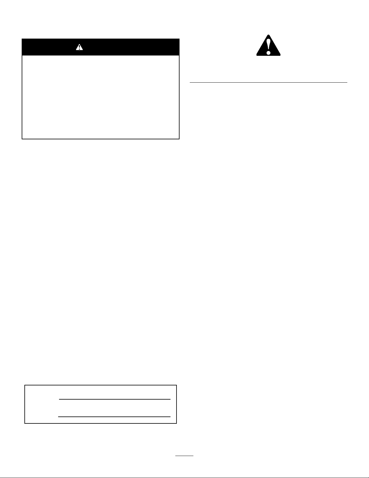
117–2718
BatterySymbols
Someorallofthesesymbolsareonyourbattery
1.Explosionhazard
2.Nore,opename,or
smoking.
3.Causticliquid/chemical
burnhazard
4.Weareyeprotection9.Flusheyesimmediately
5.ReadtheOperator's
Manual.
6.Keepbystandersasafe
7.Weareyeprotection;
8.Batteryacidcancause
10.Containslead;donot
distancefromthebattery.
explosivegasescan
causeblindnessandother
injuries
blindnessorsevereburns.
withwaterandgetmedical
helpfast.
discard.
121–5644
1.Lightswitch
2.Engage7.Lower
3.Powertake-off
4.Disengage
5.Fast
6.Slow
8.Raise
9.ReadtheOperator’s
Manual.
1.ReadtheOperator’s
Manual.
2.Engine—start4.Engine—stop
9
120–4158
3.Engine—preheat
Page 10
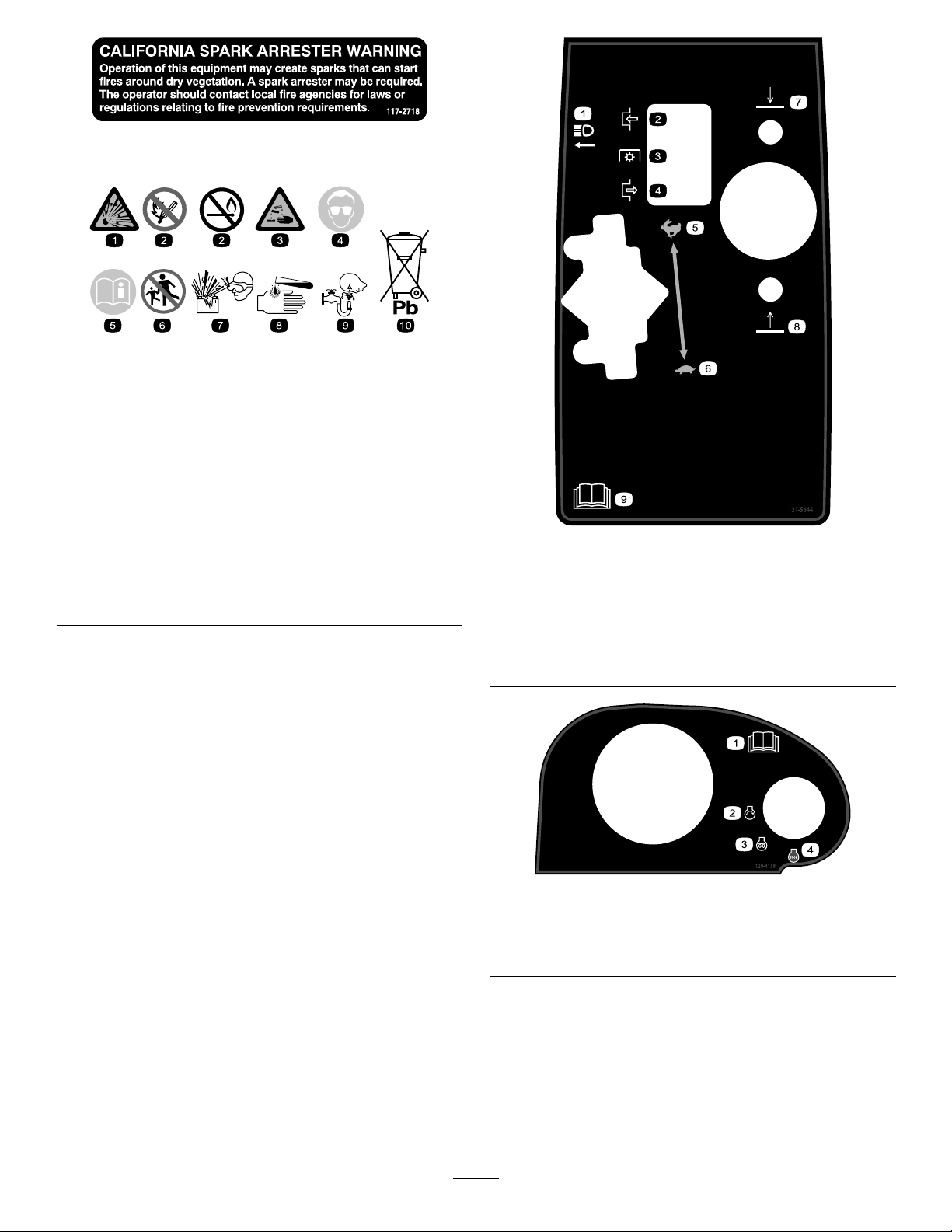
117–0169
1.ReadtheOperator'sManual.
2.Powerpoint—10amp
3.Headlights—10amp
4.Power—10amp
5.Enginestart—15amp
6.Optionalairrideseatsuspension—20amp
7.EnginecomputermanagementC—7.5amp
8.EnginecomputermanagementB—7.5amp
9.EnginecomputermanagementA—7.5amp
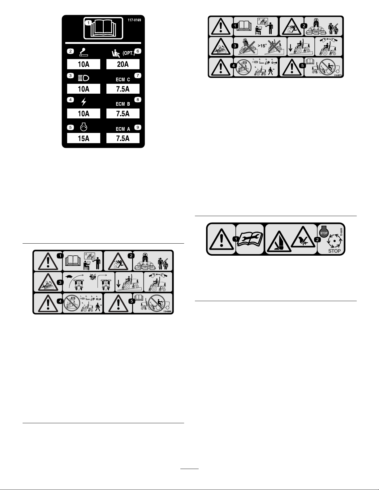
110-8973
(Afxoverpartno.110–8869forCE*)
*Thissafetydecalincludesaslopewarningrequiredonthemachinefor
compliancetotheEuropeanLawnMowerSafetyStandardENISO5395:2013.The
conservativemaximumslopeanglesindicatedforoperationofthismachineare
prescribedbyandrequiredbythisstandard.
1.Warning—readtheOperator'sManual,donotoperatethis
machineunlessyouaretrained.
2.Thrownobjecthazard—keepbystandersasafedistance
fromthemachine.
3.Tippinghazard—donotoperateonslopesgreaterthan15°;
lowerthecuttingdeckswhenoperatingonslopes;wear
thesafetybelt.
4.Warning—donotparkthemachineonslopes;engagethe
parkingbrake,lowerthecuttingdecks,stoptheengineand
removetheignitionkeybeforeleavingthemachine
5.Warning—readtheOperator'sManualbeforetowingthe
machine.
93-6688
110-8869
1.Warning—readtheOperator'sManual,donotoperatethis
machineunlessyouaretrained.
2.Thrownobjecthazard—keepbystandersasafedistance
fromthemachine.
3.Tippinghazard—slowmachinebeforeturning,donotturn
athighspeeds;lowerthecuttingunitwhendrivingdown
slopes;usearolloverprotectionsystemandweartheseat
belt.AlwayswearaseatbeltwhenaROPSisinplace.
4.Warning—donotparkthemachineonslopes;engagethe
parkingbrake,lowerthecuttingdecks,stoptheengineand
removetheignitionkeybeforeleavingthemachine.
5.Warning—readtheOperator'sManual,donottowthe
machine.
1.Warning—readthe
instructionsbefore
servicingorperforming
maintenance.
2.Cuttinghazardofhandor
foot—stoptheengineand
waitformovingpartsto
stop.
10
Page 11
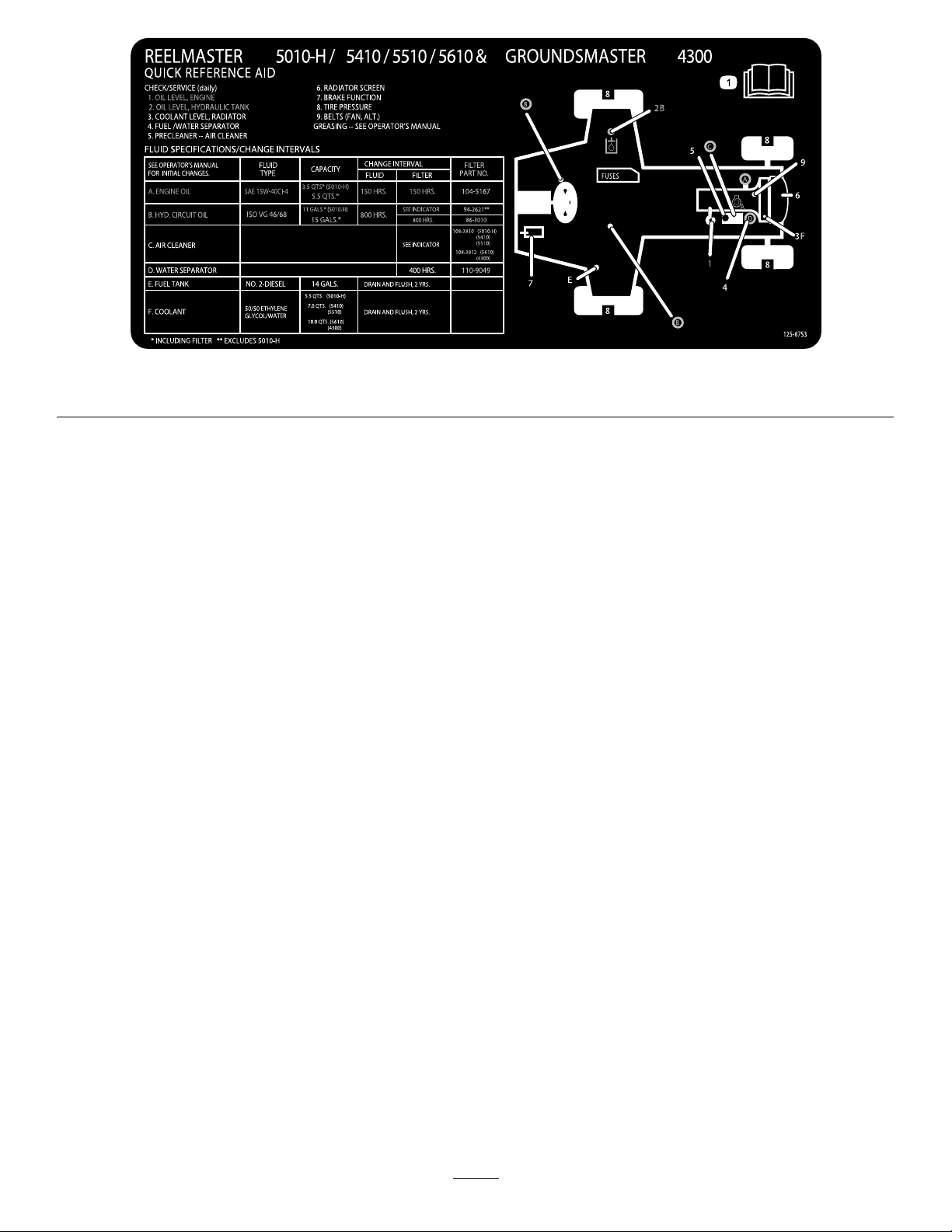
1.ReadtheOperator'sManualformoremaintenanceinformation.
125-8753
11
Page 12

Setup
LooseParts
Usethechartbelowtoverifythatallpartshavebeenshipped.
ProcedureDescription
1
2
3
4
5
6
7
Nopartsrequired
Nopartsrequired
Nopartsrequired
Fronthoseguide-R.H.1
Fronthoseguide-L.H.1
Nopartsrequired
Hoodlatchassembly1
Washer1
Cuttingunitkickstand
MediaandAdditionalParts
Description
Operator'sManual
Engineoperator’smanual1
PartsCatalog
Qty.
Qty.
–
–
–
–
1Usethecuttingunitkickstand.
1
1
Readthemanualsbeforeoperatingthemachine.
UsetothePartsCatalogtoreferencepartnumbers.
Adjustthetirepressure.
Adjustthestepheight.
Adjustthecontrolarmposition.
Installthecuttingunits
Adjusttheturfcompensationspring.
InstalltheCEhoodlatch.
Use
Use
DeclarationofConformity
Operatortrainingmaterial
Note:Determinetheleftandrightsidesofthemachine
fromthenormaloperatingposition.
1
1
1
AdjustingtheTirePressure
NoPartsRequired
Procedure
Thetiresareover-inatedforshipping.Therefore,release
someoftheairtoreducethepressure.Correctairpressurein
thefrontandreartiresis83to103kPa(12to15psi).
Important:Maintainevenpressureinalltirestoensure
uniformcontactwiththeturf.
Thisdocumentindicatesconformitywithcertainstandards.
Reviewthetrainingmaterialbeforeoperatingthemachine.
12
Page 13
2
AdjustingtheStepHeight
NoPartsRequired
Procedure
Youcanadjusttheheightofthestepsforbettercomfort.
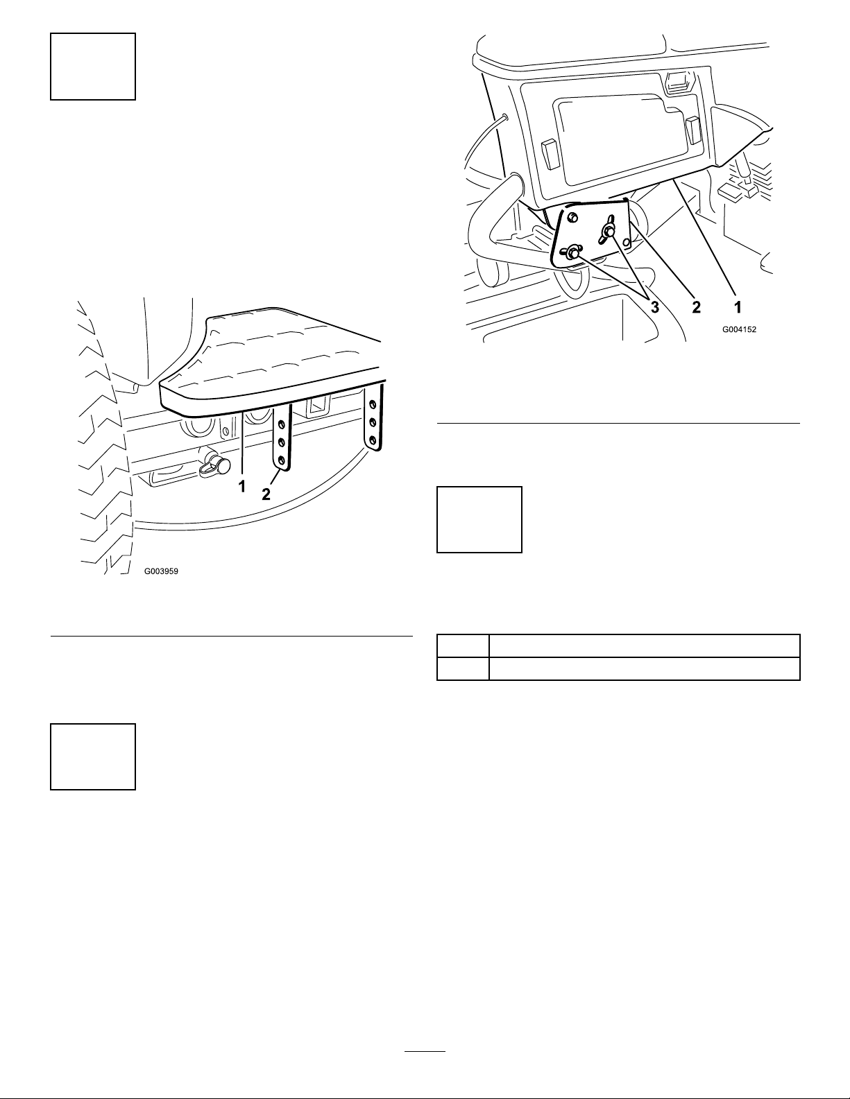
1.Removethe2boltsandnutssecuringthestepbrackets
tothetractionunitframe(Figure2)
Figure3
1.Controlarm3.Bolts(2)
2.Retainingbrackets
2.Rotatethecontrolarmtothedesiredpositionand
tightenthe2bolts.
Figure2
1.Step2.Stepbrackets
2.Raiseorlowerthesteptothedesiredheightandsecure
thebracketstotheframewiththe2boltsandnuts.
3.Repeattheprocedureontheotherstep.
3
AdjustingtheControlArm Position
NoPartsRequired
Procedure
4
InstallingtheCuttingUnits
Partsneededforthisprocedure:
1Fronthoseguide-R.H.
1Fronthoseguide-L.H.
Procedure
1.Removethereelmotorsfromtheshippingbrackets.
2.Removetheshippingbracketsanddiscard.
3.Removethecuttingunitsfromthecartons.Assemble
andadjustasdescribedinthecuttingunitOperator's
Manual.
4.Makesurethecounterweight(Figure4)isinstalledto
theproperendofthecuttingunitasdescribedinthe
cuttingunitOperator'sManual.
Thecontrolarmpositioncanbeadjustedfortheoperators
comfort.
1.Loosenthe2boltssecuringthecontrolarmtothe
retainingbracket(Figure3).
13
Page 14

Figure6
Figure4
1.Counterweight
5.Allthecuttingunitsareshippedwiththeturf
compensationspringmountedtotherightsideofthe
cuttingunit.Theturfcompensationspringmustbe
mountedtothesamesideofthecuttingunitasthe
reeldrivemotor.Repositiontheturfcompensation
asfollows:
A.Removethe2carriageboltsandnutssecuringthe
rodbrackettothecuttingunittabs(Figure5).
1.Oppositecarrierframetab
2.Rodbracket
D.Mounttherodbrackettothecuttingunittabs
withthecarriageboltsandnuts(Figure6).
Important:Onthe#4(leftfront)and#5
(rightfront)cuttingunits(Figure7),use
therodbracketmountingnutstoinstallthe
hoseguidestothefrontofthecuttingunit
tabs(Figure8).Thehoseguidesshouldlean
towardthecentercuttingunit(Figure8and
Figure9).
Figure7
Figure5
1.Turfcompensationspring3.Springtube
2.Rodbracket
B.Removetheangenutsecuringthespringtube
bolttothecarrierframetab(Figure5)Remove
theassembly.
C.Mountthespringtubebolttotheoppositetabon
thecarrierframeandsecurewiththeangenut.
Theboltheadistobepositionedtotheouterside
ofthetabasshowninFigure6.
1.Hoseguide(#4cuttingunit
shown)
2.Rodbracket
14
Figure8
3.Nuts
Page 15

g019284
1
1
1.Hoseguides(eachmustleantowardthecentercuttingunit)
Note:Wheninstallingorremovingthecutting
units,makesurethehairpincotterisinstalled
inthespringrodholenexttotherodbracket.
Otherwise,thehairpincottermustbeinstalledin
theholeintheendoftherod.
6.Loweralltheliftarmscompletely.
7.Removethesnapperpinandthecapfromtheliftarm
pivotyoke(Figure10).
Figure9
Figure11
1.Liftarm3.Liftarmpivotyoke
2.Carrierframeshaft
Figure10
1.Snapperpin2.Cap
8.Forthefrontcuttingunits,slideacuttingunitunder
theliftarmwhileinsertingthecarrierframeshaftup
intotheliftarmpivotyoke(Figure11).
9.Usethefollowingprocedureontherearcuttingunits
whentheheightofcutisabove3/4inch.
A.Removethelynchpinandwashersecuringthelift
armpivotshafttotheliftarmandslidethelift
armpivotshaftoutoftheliftarm(Figure12).
Figure12
1.Liftarmpivotshaftlynchpinandwasher
15
Page 16
B.Inserttheliftarmyokeontothecarrierframe
shaft(Figure11).
C.Inserttheliftarmshaftintotheliftarmandsecure
itwiththewasherandlynchpin(Figure12).
10.Insertthecapoverthecarrierframeshaftandliftarm
yoke.
11.Securethecapandthecarrierframeshafttothelift
armyokewiththesnapperpin.Usetheslotifasteering
cuttingunitisdesiredorusetheholeifthecuttingunit
istobelockedinposition(Figure10).
12.Securetheliftarmchaintothechainbracketwiththe
snapperpin(Figure13).Usethenumberofchainlinks
describedinthecuttingunitOperator'sManual.
Figure14
1.Reeldrivemotor2.Mountingbolts
Figure13
1.Liftarmchain3.Snapperpin
2.Chainbracket
13.Onthe#4(leftfront)and#5(rightfront)cutting
units,insertthereelmotorhosesintotherespective
hoseguide.
14.Coatthesplineshaftofthereelmotorwithclean
grease.
15.OilthereelmotorO-ringandinstallitontothemotor
ange.
16.Installthemotorbyrotatingitclockwisesothatthe
motorangesclearthebolts(Figure14).Rotatethe
motorcounterclockwiseuntiltheangesencirclethe
boltsthentightenthebolts.
Important:Makesurethereelmotorhosesare
nottwisted,kinkedorintheriskofbeingpinched.
5
AdjustingtheTurf CompensationSpring
NoPartsRequired
Procedure
Theturfcompensationspring(Figure15)transfersweight
fromthefronttotherearroller.(Thishelpstoreduceawave
patternintheturf,alsoknownasmarcellingorbobbing.)
Important:Makespringadjustmentswiththecutting
unitmountedtothetractionunit,pointingstraight
aheadandloweredtotheshopoor.
1.Makesurethehairpincotterisinstalledintherearhole
inthespringrod(Figure15).
16
Page 17

Figure15
1.Turfcompensationspring3.Springrod
2.Hairpincotter4.Hexnuts
2.Tightenthehexnutsonthefrontendofthespringrod
untilthecompressedlengthofthespringis12.7cm
(5inches)onReelmaster5410,5-inchcuttingunitsor
15.9cm(6.25inches)onReelmaster5510and5610,
7-inchcuttingunits(Figure15).
Note:Whenoperatingonroughterraindecreasethe
springlengthby13mm(1/2inch).Groundfollowing
willbeslightlydecreased.
17
Page 18

rubbersealingwasherremainstotheoutersideofthe
hood(Figure17).
6
InstallingtheCEHoodLatch
Partsneededforthisprocedure:
1Hoodlatchassembly
1Washer
Procedure
1.Unlatchandraisethehood.
2.Removetherubbergrommetfromtheholeintheleft
sideofthehood(Figure16).
5.Insidethehood,insertthemetalwasherontothelatch
andsecurewiththenut.Makesurethatthelatch
engagestheframecatchwhenitislocked.Usethe
enclosedhoodlatchkeytooperatethehoodlatch.
7
UsingtheCuttingUnit Kickstand
Partsneededforthisprocedure:
1
Cuttingunitkickstand
Procedure
Wheneverthecuttingunithastobetippedtoexposethe
bedknifeandthereel,propuptherearofthecuttingunit
withthekickstandtomakesurethatthenutsonthebackend
ofthebedbaradjustingscrewsarenotrestingonthework
surface(Figure18).
Figure16
1.Rubbergrommet
3.Removethenutfromthehoodlatchassembly(Figure
17).
Figure17
1.Hoodlatch3.Rubberwasher
2.Nut4.Metalwasher
4.Outsidethehood,insertthehookendofthelatch
throughtheholeinthehood.Makesurethatthe
Figure18
1.Cuttingunitkickstand
Securethekickstandtothechainbracketwiththesnapper
pin(Figure19).
18
Page 19

Figure19
1.Chainbracket3.Cuttingunitkickstand
2.Snapperpin
ProductOverview
Controls
SeatAdjustingKnobs
Theseatadjustinglever(Figure20)allowsyoutoadjustthe
seatforeandaft.Theweightadjustingknobadjuststheseat
fortheoperator'sweight.Theweightgaugeindicateswhen
theseatisadjustedtotheweightoftheoperator.Theheight
adjustingknobadjuststheseatfortheoperator'sheight.
Figure20
1.Weightgauge3.Heightadjustingknob
2.Weightadjustingknob
4.Adjustinglever(foreand
aft)
TractionPedal
Thetractionpedal(Figure21)controlstheforwardand
reverseoperation.Pressthetopofthepedaltomovethe
machineforwardandthebottomtomovethemachine
backward.Groundspeeddependsonhowfaryoupressthe
pedal.Fornoload,maximumgroundspeed,fullypressthe
pedalwhilethethrottleisintheFastposition.
Tostopthemachine,reducefootpressureonthetraction
pedalandallowittoreturntothecenterposition.
19
Page 20

ThrottleControl
Movethethrottlecontrol(Figure22)forwardtoincreasethe
enginespeedandrearwardtodecreasespeed.
Figure21
1.Tractionpedal4.Brakepedal
2.Mow/transportlever
3.Mowspeedlimiterand
spacers
5.Parkingbrake
6.Tiltsteeringpedal
Mow/TransportLever
Usethemow/transportlever(Figure21)toputthemachine
intoMowmodeorTransportmode.Pushtheleverforward
toselecttheMowmode,andbackwardtoselecttheTransport
mode.
Note:Thecuttingunitscannotbeloweredwhenthe
mow/transportleverisinthetransportposition.
MowSpeedLimiter
Whenthemowspeedlimiter(Figure21)isipped
up/forwarditlimitsthemowspeedandallowthecutting
unitstobeengaged.Eachspaceradjuststhemowingspeed
by0.8km/h(½mph).Themorespacersthereareonthetop
ofthebolt,theslowerthemachinegoes.Flipthemowspeed
limiterbackwardtoallowmaximumtransportspeed.
Figure22
1.Lowermow/raisecontrol
lever
2.Keyswitch5.Throttlecontrol
3.InfoCenter
4.Enable/disableswitch
6.Headlightswitch
KeySwitch
Thekeyswitch(Figure22)has3positions:Off,On/Preheat,
andStart.
LowerMow/RaiseControlLever
Thislever(Figure22)raisesandlowersthecuttingunitsand
alsostartsandstopsthecutterheadswhenthecutterheads
areenabledinthemowmode.
HeadlightSwitch
Pivottheswitchdownwardtoturnontheheadlights(Figure
22).
Enable/DisableSwitch
BrakePedal
Pressthebrakepedal(Figure21)tostopthemachine.
ParkingBrake
Toengagetheparkingbrake,(Figure21)pushdownonthe
brakepedalandpressthetopforwardtolatchit.Torelease
theparkingbrake,pressthebrakepedaluntiltheparking
brakelatchretracts.
TiltSteeringPedal
Totiltthesteeringwheeltowardsyou,pressthefootpedal
(Figure21)down,andpullthesteeringtowertowardyouto
themostcomfortablepositionandthenreleasethepedal.
Usetheenable/disableswitch(Figure22)inconjunctionwith
thelowermow/raisecontrollevertooperatethecutterheads.
Thecutterheadscannotbeloweredwhenthemow/transport
leverisinthetransportposition.
BacklapLevers
Usethebacklapleversinconjunctionwiththelower
mow/raisecontrolleverforbacklappingthereels(Figure23).
20
Page 21

1
g021209
Figure23
1.Backlaplevers
HydraulicFilterRestrictionIndicator
Withtheenginerunningatnormaloperatingtemperature,
viewtheindicator(Figure24),itshouldbeinthegreenzone.
Whentheindicatorisintheredzone,changethehydraulic
lters.
Figure25
1.Powerpoint
Figure24
1.Hydrauliclterrestrictionindicator
PowerPoint
Thepowerpointisa12-voltpowersupplyforelectronic
devices(Figure25).
21
Page 22

UsingtheInfoCenterLCDDisplay
1
g020650
2
3
4
TORO
TheInfoCenterLCDdisplayshowsinformationaboutyour
machinesuchastheoperatingstatus,variousdiagnostics
andotherinformationaboutthemachine(Figure26)There
isasplashscreenandmaininformationscreenofthe
InfoCenter.Youcanswitchbetweenthesplashscreenand
maininformationscreen,atanytime,bypressinganyof
theInfoCenterbuttonsandthenselectingtheappropriate
directionalarrow .
InfoCenterIconDescription(cont'd.)
Glowplugsareactive
Raisecuttingunits
Lowercuttingunits
Operatormustsitinseat
ParkingBrakeIndicator—indicates
whentheparkingbrakeisOn
IdentiestherangeasHigh
(Transport)
Neutral
IdentiestherangeasLow(Mow)
Figure26
1.Indicatorlight3.Middlebutton
2.Rightbutton
4.Leftbutton
•Leftbutton,menuaccess/backbutton—pressthis
buttontoaccesstheInfoCentermenus.Youcanuseitto
backoutofanymenuyouarecurrentlyusing.
•Middlebutton—usethisbuttontoscrolldownmenus.
•Rightbutton—usethisbuttontoopenamenuwherea
rightarrowindicatesadditionalcontent.
Note:Thepurposeofeachbuttonmaychangedepending
onwhatisrequiredatthetime.Eachbuttonwillbelabeled
withanicondisplayingitscurrentfunction.
InfoCenterIconDescription
SERVICEDUE
Indicateswhenscheduledservice
shouldbeperformed
Hourmeter
Infoicon
CoolantTemperature-indicatesthe
enginecoolanttemperatureineither
°Cor°F
Temperature(hot)
PTOisengaged
Deniedornotallowed
EngineStart
Stoporshutdown
Engine
Keyswitch
Indicateswhenthecuttingunitsare
beinglowered
Indicateswhenthecuttingunitsare
beingraised
PINpasscode
Fast
CANbus
Slow
Fuellevel
InfoCenter
Badorfailed
22
Page 23

InfoCenterIconDescription(cont'd.)
Bulb
OutputofTECcontrollerorcontrol
wireinharness
Switch
Operatormustreleaseswitch
Operatorshouldchangetoindicated
state
DiagnosticsTheDiagnosticsmenu
displaysthestateofeach
machineswitch,sensor,and
controloutput.Y oucanuse
thistotroubleshootcertain
issuesasitwillquicklytellyou
whichmachinecontrolsareon
andwhichareoff.
SettingsTheSettingsmenuallows
youtocustomizeandmodify
congurationvariablesonthe
InfoCenterdisplay.
AboutTheAboutmenuliststhe
modelnumber,serialnumber,
andsoftwareversionofyour
machine.
Symbolsareoften
combinedtoform
sentences.Some
examplesareshown
below
Operatorshouldputmachinein
neutral
Enginestartdenied
Engineshutdown
Enginecoolanttoohot
Sitdownorsetparkingbrake
UsingtheMenus
ToaccesstheInfoCentermenusystem,pressthemenuaccess
buttonwhileatthemainscreen.Thiswillbringyoutothe
mainmenu.Refertothefollowingtablesforasynopsisof
theoptionsavailablefromthemenus:
MainMenu
MenuItemDescription
FaultsTheFaultsmenucontains
alistoftherecentmachine
faults.RefertotheService
ManualoryourAuthorized
ToroDistributorformore
informationontheFaults
menuandtheinformation
containedthere.
ServiceTheServicemenucontains
informationonthemachine
suchashoursofuse,counters,
andothersimilarnumbers.
Service
MenuItemDescription
Hours
Counts
Diagnostics
MenuItemDescription
CuttingUnitsIndicatestheinputs,qualiers,
Hi/LowRangeIndicatestheinputs,qualiers,
PTOIndicatestheinputs,qualiers,
EngineRun
Backlap
Settings
MenuItemDescription
Units
Language
LCDBacklightControlsthebrightnessofthe
LCDContrastControlsthecontrastofthe
Liststhetotalnumberofhours
thatthemachine,engineand
PTOhavebeenon,aswell
asthenumberofhoursthe
machinehasbeentransported
andservicedue.
Listsnumerouscountsthe
machinehasexperienced.
andoutputsforraisingand
loweringthecuttingunits.
andoutputsfordrivingin
transportmode.
andoutputsforenablingthe
PTOcircuit.
Indicatestheinputs,qualiers,
andoutputsforstartingthe
engine.
Indicatestheinputs,qualiers
andoutputsforoperatingthe
backlapfunction.
Controlstheunitsusedonthe
InfoCenter.Themenuchoices
areEnglishorMetric.
Controlsthelanguageused
ontheInfoCenter*.
LCDdisplay.
LCDdisplay.
23
Page 24

FrontBacklapReelSpeedControlsthespeedofthefront
reelsinbacklapmode.
RearBacklapReelSpeedControlsthespeedoftherear
reelsinbacklapmode.
ProtectedMenusAllowsthe
superintendant/mechanic
toaccessprotectedmenusby
inputtingapasscode.
BladeCountControlsthenumberofblades
onthereelforreelspeed.
MowSpeedControlsthegroundspeedfor
determiningthereelspeed.
Heightofcut(HOC)Controlstheheightofcut
(HOC)fordeterminingthereel
speed.
FReelRPMDisplaysthecalculatedreel
speedpositionforthefront
reels.Thereelscanalsobe
manuallyadjusted.
RReelRPMDisplaysthecalculatedreel
speedpositionfortherear
reels.Thereelscanalsobe
manuallyadjusted.
AccessingtheProtectedMenuSettings
ToaccesstheProtectedMenuSettings
•FromtheMainMenu,scrolldowntotheSettingsMenu
andpresstherightbutton.
•IntheSettingsMenu,scrolldowntotheProtectedMenu
andpresstherightbutton.
•Toenterthepasscode,usethecenterbuttontosetthe
rstdigitthenpresstherightbuttontomoveontothe
nextdigit.
•Usethecenterbuttontosettheseconddigitthenpress
therightbuttontomoveontothenextdigit.
•Usethecenterbuttontosetthethirddigitthenpressthe
rightbuttontomoveontothenextdigit.
•Usethecenterbuttontosetthefourthdigitthenpress
therightbutton.
•Pressthemiddlebuttontoenterthecode.
•Ifthecodehasbeenacceptedandtheprotectedmenuhas
been“Unlocked”,“PIN”willbedisplayedintheupper
rightcornerofthedisplayscreen.
*Only"operator-faced"textistranslated.Faults,Service,and
Diagnosticsscreensare"service-faced".Titleswillbeinthe
selectedlanguage,butmenuitemsareinEnglish.
About
MenuItemDescription
Model
SNListstheserialnumberofthe
MachineControllerRevisionListsthesoftwarerevisionof
InfoCenterRevisionListsthesoftwarerevisionof
CANBus
Liststhemodelnumberofthe
machine.
machine.
themastercontroller .
theInfoCenter.
Liststhemachine
communicationbusstatus.
ProtectedMenu
Thereare5operatingcongurationsettingsthatare
adjustablewithintheSettingsMenuoftheInfoCenter:Blade
Count,MowSpeed,HeightofCut(HOC),FReelRPM,
andRReelRPM.Thesesettingscanbelockedbyusingthe
ProtectedMenu.
Note:Atthetimeofdelivery,theinitialpasswordcodeis
programmedbyyourdistributor.
TheabilitytoviewandchangethesettingsintheProtected
Menucanbechanged.OncetheProtectedMenuhasbeen
accessed,scrolldowntoProtectSettings.Usingtheright
button,changingProtectSettingstoOFFwillallowthe
abilitytoviewandchangethesettingsintheProtectedMenu
withoutenteringthepasscode.ChangingProtectSettingsto
ONwillhidetheprotectedoptionsandwillrequireenteringa
passcodetochangethesettingintheProtectedMenu.After
thepasscodehasbeenset,thekeyswitchmustbeturnedoff
andbackontoenableandsavethisfeature.
Note:Ifthepasscodehasbeenforgottenormisplaced,
pleasecontactyourdistributorforassistance.
SettingtheBladeCount
•IntheSettingsMenu,scrolldowntoBladeCount
•Presstherightbuttontochangethebladecountbetween
5,8,or11bladereels.
SettingtheMowSpeed
•IntheSettingsMenu,scrolldowntoMowSpeed.
•Presstherightbuttontoselectmowspeed.
•Usethecenterandrightbuttontoselecttheappropriate
mowspeedsetonthemechanicalmowspeedlimiteron
thetractionpedal.
•Presstheleftbuttontoexitmowspeedandsavethe
setting.
SettingtheHeightofCut(HOC)
•IntheSettingsMenu,scrolldowntoHOC.
•PresstherightbuttontoselectHOC.
24
Page 25

•Usethecenterandrightbuttontoselecttheappropriate
HOCsetting.(Iftheexactsettingisnotdisplayed,select
thenearestHOCsettingfromthelistdisplayed).
•PresstheleftbuttontoexitHOCandsavethesetting.
theInfoCenter,thesettingcanbemanuallychangedto
accommodatefordifferentmowingconditions.
•TochangetheReelSpeedSettings,scrolldowntotheF
ReelRPM,RReelRPMorboth.
•Presstherightbuttontochangethereelspeedvalue.As
SettingtheFrontandRearReelSpeeds
Althoughthefrontandrearreelspeedsarecalculatedby
inputtingthenumberofblades,mowspeedandHOCinto
thespeedsettingischanged,thedisplaywillcontinueto
showthecalculatedreelspeedbasedonbladecount,
mowspeedandHOCwhichwaspreviouslyentered,but
thenewvaluewillalsobedisplayed.
Specications
Note:Specicationsanddesignaresubjecttochange
withoutnotice.
SpecicationReelMaster®5410ReelMaster®5510ReelMaster®5610
TransportWidth
Widthofcut254cm(100inches)254cm(100inches)254cm(100inches)
Length
Height
Weight
228cm(90inches)233cm(92inches)233cm(92inches)
282cm(111inches)282cm(111inches)282cm(111inches)
160cm(63inches)160cm(63inches)160cm(63inches)
1,136kg(2,505lb)1,222kg(2,693lb)1,276kg(2,813lb)
EngineKubota35.5hpKubota35.5hp
Fueltankcapacity
Transportspeed
Mowingspeed
53liters(14USgallons)53liters(14USgallons)53liters(14USgallons)
0–16km/h(0–10mph)0–16km/h(0–10mph)0–16km/h(0–10mph)
0–13km/h(0–8mph)0–13km/h(0–8mph)0–13km/h(0–8mph)
Attachments/Accessories
AselectionofToroapprovedattachmentsandaccessoriesis
availableforusewiththemachinetoenhanceandexpand
itscapabilities.ContactyourAuthorizedServiceDealeror
Distributororgotowww .Toro.comforalistofallapproved
attachmentsandaccessories.
Kubota44.2hp(turbo)
25
Page 26

Operation
Note:Determinetheleftandrightsidesofthemachine
fromthenormaloperatingposition.
CAUTION
Ifyouleavethekeyintheignitionswitch,someone
couldaccidentlystarttheengineandseriously
injureyouorotherbystanders.
Lowerthecuttingunitstotheground,setthe
parkingbrakeandremovethekeyfromtheignition
switchbeforeservicingormakingadjustmentsto
themachine.
CheckingtheEngine-OilLevel
Theengineisshippedwithoilinthecrankcase;however,the
oillevelmustbecheckedbeforeandaftertheengineisrst
started.
Crankcasecapacity:approximately5.2liters(5.5USqt)
withthelter
Usehigh-qualityengineoilthatmeetsthefollowing
specications:
•APIClassicationLevelRequired:CH-4,CI-4orhigher
•Preferredoil:SAE15W-40(above0degreesF)
•Alternateoil:SAE10W-30or5W-30(alltemperatures)
ToroPremiumEngineoilisavailablefromyourdistributorin
either15W -40or10W-30viscosity .
1.Parkthemachineonalevelsurface,stoptheengine,
settheparkingbrakeandremovethekeyfromthe
ignitionswitch.
2.Openthehood.
3.Removethedipstick,wipeitclean,andinstallit(Figure
27).
Figure27
1.Dipstick
4.Removedipstickandcheckoillevelondipstick.
Note:TheoillevelshouldbeuptotheFullmark.
5.IftheoillevelisbelowtheFullmark,removethell
cap(Figure28)andaddoiluntilthelevelreachesthe
Fullmarkonthedipstick.
1.Oil-llcap
Donotoverlltheengine.
Important:Besuretokeeptheengine-oillevel
betweentheupperandlowerlimitsontheoil
gauge.Enginefailuremayoccurasaresultof
overllingorunderllingtheengineoil.
6.Installtheoil-llcapandclosethehood.
26
Figure28
Page 27

CheckingtheCoolingSystem
AddingFuel
Cleandebrisoffofthescreen,oilcooler,andfrontofthe
radiatordailyandmoreoftenifconditionsareextremely
dustyanddirty.RefertoRemovingDebrisfromtheCooling
System(page45).
Thecoolingsystemislledwitha50/50solutionofwater
andpermanentethyleneglycolantifreeze.Checkthelevelof
coolantintheexpansiontankatthebeginningofeachday
beforestartingtheengine.Thecapacityofthecoolingsystem
formodels5410and5510is6.6liters(7.0USquarts)and
model5610is9.5liters(10.0USquarts).
CAUTION
Iftheenginehasbeenrunning,thepressurized,hot
coolantcanescapeandcauseburns.
•Donotopentheradiatorcapwhentheengine
isrunning.
•Usearagwhenopeningtheradiatorcap,and
openthecapslowlytoallowsteamtoescape.
1.Checkthelevelofcoolantintheexpansiontank
(Figure29).
Thecoolantlevelshouldbebetweenthemarksonthe
sideofthetank.
Useonlyclean,freshdieselfuelorbiodieselfuelswithlow
(<500ppm)orultralow(<15ppm)sulfurcontent.The
minimumcetaneratingshouldbe40.Purchasefuelin
quantitiesthatcanbeusedwithin180daystoensurefuel
freshness.
Fueltankcapacity:53liters(14USgallons)
Usesummer-gradedieselfuel(No.2-D)attemperatures
above20°F(-7°C)andwinter-gradedieselfuel(No.1-D
orNo.1-D/2-Dblend)belowthattemperature.Useof
winter-gradefuelatlowertemperaturesprovideslowerash
pointandcoldowcharacteristicswhichwilleasestarting
andreducefuellterplugging.
Useofsummer-gradefuelabove20°F(-7°C)willcontribute
towardlongerfuelpumplifeandincreasedpowercompared
towinter-gradefuel.
Important:Donotusekeroseneorgasolineinsteadof
dieselfuel.Failuretoobservethiscautionwilldamage
theengine.
WARNING
Fuelisharmfulorfatalifswallowed.Long-term
exposuretovaporscancauseseriousinjuryand
illness.
Figure29
1.Expansiontank
2.Ifthecoolantlevelislow,removetheexpansion-tank
capandreplenishthesystem.Donotoverllthetank.
3.Installtheexpansion-tankcap.
•Avoidprolongedbreathingofvapors.
•Keepfaceawayfromnozzleandgastankor
conditioneropening.
•Keepfuelawayfromeyesandskin.
BiodieselReady
Thismachinecanalsouseabiodieselblendedfuelofup
toB20(20%biodiesel,80%petrodiesel).Thepetrodiesel
portionshouldbeloworultra-lowsulfur.Observethe
followingprecautions:
•Thebiodieselportionofthefuelmustmeetspecication
ASTMD6751orEN14214.
•TheblendedfuelcompositionshouldmeetASTMD975
orEN590.
•Paintedsurfacesmaybedamagedbybiodieselblends.
•UseB5(biodieselcontentof5%)orlesserblendsincold
weather.
•Monitorseals,hoses,andgasketsincontactwithfuelas
theymaybedegradedovertime.
•Fuellterpluggingmaybeexpectedforatimeafter
convertingtobiodieselblendedfuel.
•Contactyourdistributorifyouwishformoreinformation
onbiodiesel.
27
Page 28

DANGER
1
G021210
Incertainconditions,fuelisextremelyammable
andhighlyexplosive.Areorexplosionfromfuel
canburnyouandothersandcandamageproperty.
•Fillthefueltankoutdoors,inanopenarea,when
theengineiscold.Wipeupanyfuelthatspills.
•Neverllthefueltankinsideanenclosedtrailer.
•Neversmokewhenhandlingfuel,andstayaway
fromanopenameorwherefuelfumesmaybe
ignitedbyaspark.
•Storefuelinanapprovedcontainerandkeepit
outofthereachofchildren.Donotbuymore
thana30-daysupplyoffuel.
•Donotoperatewithoutentireexhaustsystemin
placeandinproperworkingcondition.
DANGER
Incertainconditionsduringfueling,static
electricitycanbereleasedcausingasparkwhich
canignitethefuelvapors.Areorexplosionfrom
fuelcanburnyouandothersandcandamage
property.
•Alwaysplacefuelcontainersonthegroundaway
fromyourvehiclebeforelling.
•Donotllfuelcontainersinsideavehicleoron
atruckortrailerbedbecauseinteriorcarpets
orplastictruckbedlinersmayinsulatethe
containerandslowthelossofanystaticcharge.
•Whenpractical,removeequipmentfromthe
truckortrailerandrefueltheequipmentwithits
wheelsontheground.
•Ifthisisnotpossible,thenrefuelsuchequipment
onatruckortrailerfromaportablecontainer,
ratherthanfromafueldispensernozzle.
•Ifafueldispensernozzlemustbeused,keepthe
nozzleincontactwiththerimofthefueltank
orcontaineropeningatalltimesuntilfuelingis
complete.
1.Parkthemachineonalevelsurface.
2.Usingacleanrag,cleantheareaaroundthefuel-tank
cap.
3.Removethecapfromthefueltank(Figure30).
Figure30
1.Fuel-tankcap
4.Fillthetankuntilthelevelistothebottomoftheller
neckwithdieselfuel.
5.Installthefuel-tankcaptightlyafterllingthetank.
Note:Ifpossible,llthefueltankaftereachuse.This
willminimizepossiblebuildupofcondensationinside
thefueltank.
CheckingtheHydraulicFluid
Thereservoirislledatthefactorywithapproximately56.7
liters(15USgallons)ofhigh-qualityhydraulicuid.Thebest
timetocheckthehydraulicoiliswhentheuidiscold.The
machineshouldbeinitstransportconguration.Iftheoil
levelisbelowthe‘add’markonthedipstick,addoiltobring
theoilleveltothemiddleoftheacceptablerange.Donot
overllthereservoir.Iftheoillevelisbetweenthe‘full’and
the‘add’marks,nooiladditionisrequired.
Therecommendedreplacementuidis:
ToroPremiumAllSeasonHydraulicFluid
(availablein19liter(5gallon)containersor208liter(55
gallon)drums—seethepartsdocumentationoryourToro
distributorforpartnumbers)
Alternativeuids:IftheTorouidisnotavailable,other
conventional,petroleum-baseduidsmaybeused,provided
thattheymeetallofthefollowingmaterialpropertiesand
industryspecications.Checkwithyouroilsuppliertosee
whethertheoilmeetsthesespecications.
Note:Torowillnotassumeresponsibilityfordamage
causedbyimpropersubstitutions,souseonlyproducts
fromreputablemanufacturerswhowillstandbehindtheir
recommendation.
HighViscosityIndex/LowPourPointAntiwearHydraulic
Fluid,ISOVG46Multigrade
MaterialProperties:
Viscosity,ASTMD445cSt@40°C(104°F)
Viscosityindex,ASTM
D2270
44to48
cSt@100°C(212°F)
7.9to9.1
140orhigher(high
viscosityindexindicatesa
multiweightuid)
28
Page 29

Pourpoint,ASTMD97-36.7°Cto-45°C(-34°Fto
1
g021215
FZG,failstage
Watercontent(newuid)500ppm(maximum)
IndustrySpecications:
VickersI-286-S,VickersM-2950-S,DenisonHF-0,
Vickers35VQ25(EatonATS373-C)
Theproperhydraulicuidsmustbespeciedfor
mobilemachinery(asopposedtoindustrialplantusage),
multiweight-type,withZnDTPorZDDPanti-wearadditive
package(notanashless-typeuid).
-49°F)
11orbetter
3.Removecap/dipstickfromllerneckandwipeitwith
acleanrag.Insertdipstickintollerneck;thenremove
itandchecklevelofuid.Fluidlevelshouldbewithin
operatingrangeondipstick.Donotoverllthetank.
4.Ifthelevelislow ,addtheappropriateuidtoraisethe
leveltothefullmark.
5.Installcap/dipstickontollerneck.
CheckingtheReeltoBedknife
Important:Manyhydraulicuidsarealmostcolorless,
makingitdifculttospotleaks.Areddyeadditivefor
thehydraulicsystemoilisavailablein20ml(2/3oz)
bottles.Onebottleissufcientfor15to22liters(4to6
USgallons)ofhydraulicoil.Orderpart44-2500from
yourAuthorizedT oroDistributor.
Synthetic,BiodegradableHydraulicFluid
(availablein19liter(5gallon)containersor208liter(55
gallon)drums—seethepartsdocumentationoryourToro
distributorforpartnumbers)
Thishigh-quality,synthetic,biodegradableuidhasbeen
testedandfoundcompatibleforthisToromodel.Other
brandsofsyntheticuidmayhavesealcompatibilityproblems
andTorocannotassumeresponsibilityforunauthorized
substitutions.
Note:Thissyntheticuidisnotcompatiblewiththe
ToroBiodegradableFluidpreviouslysold.SeeyourToro
Distributorformoreinformation.
Alternativeuids:
•MobilEALEnvirosynH46(US)
•MobilEALHydraulicOil46(international)
1.Positionmachineonalevelsurface,lowerthecutting
decksandstoptheengine.
2.Cleanareaaroundllerneckandcapofhydraulictank
(Figure31).
Contact
Eachdaybeforeoperating,checkthereel-to-bedknifecontact,
regardlessofwhetherthequalityofcuthadpreviouslybeen
acceptable.Theremustbelightcontactacrossthefulllength
ofthereelandthebedknife(refertoAdjustingtheReelto
BedknifeinthecuttingunitOperator'sManual).
CheckingtheTorqueofthe WheelNuts
Torquethewheelnutsto94to122N-m(70to90ft-lb)
after1to4hoursofoperationandagainafter10hoursof
operation.Torquethewheelnutsevery250hoursthereafter.
WARNING
Failuretomaintainpropertorqueofthewheelnuts
couldresultinpersonalinjury.
Breaking-intheMachine
Toensureoptimumperformanceoftheparkingbrakesystem,
burnish(break-in)thebrakesbeforeuse.Settheforward
tractionspeedto6.4km/h(4mph)tomatchthereverse
tractionspeed.(All8spacersmovedtothetopofthemow
speedcontrol.)Withtheengineathighidle,proceedforward
withthemowspeedcontrolstopengagedandridethebrake
for15seconds.Proceedbackwardsatfullreversespeedand
ridethebrakefor15seconds.Repeatthis5timeswaiting
1minutebetweeneachforwardandreversecycletoavoid
overheatingthebrakes.Anadjustmenttothebrakesmaybe
requiredafterbreak-in;refertoAdjustingtheParkingBrakes
(page46).
1.Hydraulic-tankcap
BleedingtheFuelSystem
Youmustbleedthefuelsystembeforestartingtheengineif
anyofthefollowingsituationshaveoccurred:
•Initialstartupofanewmachine
•Theenginehasceasedrunningduetolackoffuel.
Figure31
•Maintenancehasbeenperformeduponfuelsystem
components;i.e.,lterreplaced,separatorserviced,etc.
29
Page 30

DANGER
Undercertainconditions,dieselfuelandfuel
vaporsarehighlyammableandexplosive.Are
orexplosionfromfuelcanburnyouandothersand
cancausepropertydamage.
Note:Normally,theengineshouldstartaftertheabove
bleedingproceduresarefollowed.However,ifenginedoes
notstart,airmaybetrappedbetweeninjectionpumpand
injectors;refertoBleedingAirfromtheFuelInjectors(page
42).
•Useafunnelandllthefueltankoutdoors,in
anopenarea,whentheengineisoffandiscold.
Wipeupanyfuelthatspills.
•Donotllthefueltankcompletelyfull.Add
fueltothefueltankuntilthelevelis6to13mm
(1/4to1/2inch)belowthebottomoftheller
neck.Thisemptyspaceinthetankallowsthe
fueltoexpand.
•Neversmokewhenhandlingfuel,andstayaway
fromanopenameorwherefuelfumesmaybe
ignitedbyaspark.
•Storefuelinaclean,safety-approvedcontainer
andkeepthecapinplace.
1.Parkthemachineonalevelsurfaceandensurethatthe
fueltankisatleasthalffull.
2.Openthehood.
3.Opentheair-bleedscrewonthefuel-injectionpump
(Figure32)witha12mmwrench.
StartingandStoppingthe Engine
Important:Y oumustbleedthefuelsystembefore
startingtheengineifyouarestartingtheengineforthe
rsttime,theenginehasstoppedduetolackoffuel,or
youhaveperformedmaintenanceonthefuelsystem;
refertoBleedingtheFuelSystem(page29).
StartingtheEngine
1.Sitontheseat,keepyourfootoffofthetractionpedal
sothatitisinNeutral,engagetheparkingbrake,set
thethrottletotheFastposition,andensurethatthe
Enable/DisableswitchisintheDisableposition.
2.TurntheignitionswitchtotheOn/Preheatposition.
Anautomatictimerwillcontroltheglowplugpreheat
for6seconds.
3.Afterpreheatingtheglowplugs,turnkeytotheStart
position.
Cranktheenginefornolongerthan15seconds.
Releasethekeywhentheenginestarts.Ifadditional
preheatingisrequired,turnkeytotheOffpositionand
thentotheOn/Preheatposition.Repeatthisprocess
asrequired.
Figure32
1.Bleedscrew
4.TurnthekeyintheignitionswitchtotheOnposition.
Theelectricfuelpumpwillbeginoperation,thereby
forcingairoutaroundtheair-bleedscrew.Leavethe
keyintheOnpositionuntilasolidstreamoffuelows
outaroundthescrew .
5.TightenthescrewandturnthekeytotheOffposition.
4.Runtheengineatlowidlespeeduntilitwarmsup.
StoppingtheEngine
1.MoveallcontrolstoNeutral,settheparkingbrake,
movethethrottletothelowidlepositionandallowthe
enginetoreachlowidlespeed.
Important:Allowtheenginetoidlefor5
minutesbeforeshuttingitoffafterafullload
operation.Failuretodosomayleadtotroubleon
aturbo-chargedengine.
2.TurnthekeytotheOffpositionandremoveitfrom
theswitch.
SettingtheReelSpeed
Toachieveaconsistent,highqualityofcutandauniform
aftercutappearance,itisimportantthatyousetthereelspeed
tothepropersetting.Adjustthereelspeedasfollows:
1.IntheInfoCenter,underthesettingsmenu,enterthe
bladecount,mowspeedandHOCtocalculatethe
properreelspeed.
30
Page 31

2.Iffurtheradjustmentsarerequired,inthesettings
g019276
1
2
menu,scrolldowntotheFReelRPM,RReelRPM
orboth.
3.Presstherightbuttontochangethereelspeedvalue.
Asthespeedsettingischanged,thedisplaywill
continuetoshowthecalculatedreelspeedbasedon
bladecount,mowspeedandHOC,butthenewvalue
willalsobedisplayed.
Note:Thereelspeedmayneedtobeincreasedor
decreasedtocompensateforvaryingturfconditions.
AdjustingtheLiftArm Counterbalance
Youcanadjustthecounterbalanceontherearcuttingunit
liftarmstocompensatefordifferentturfconditionsandto
maintainauniformheightofcutintheroughconditionsor
inareasofthatchbuildup.
Youcanadjusteachcounterbalancespringtooneof
foursettings.Eachincrementincreasesordecreases
counterbalanceonthecuttingunitby2.3kg(5lb).The
springscanbepositionedonthebacksideoftherstspring
actuatortoremoveallcounterbalance(fourthposition).
AdjustingtheLiftArmTurn AroundPosition
1.Positionthemachineonalevelsurface,lowerthe
cuttingunits,stoptheengine,engagetheparking
brakes,andremovethekeyfromignitionswitch.
2.Theliftarmswitchislocatedunderneaththehydraulic
tankbehindthefrontrightliftarm(Figure34).
3.Loosentheswitchmountingscrews(Figure34)and
movetheswitchdowntoincreasetheliftarmturn
aroundheightormovetheswitchuptodecreasethelift
armturnaroundheight.Tightenthemountingscrews.
1.Positionthemachineonalevelsurface,lowerthe
cuttingunits,stoptheengine,engagetheparking
brakes,andremovethekeyfromignitionswitch.
2.Insertatubeorsimilarobjectontothelongspringend
andpivotitaroundthespringactuatortothedesired
position(Figure33).
CAUTION
Thespringsareundertensionandcouldcause
personalinjury.
Usecautionwhenadjustingthem.
Figure34
1.Switch2.Liftarmsensingdevice
LocatingtheJackingPoints
Note:Usejackstandstosupportthemachinewhenrequired.
•Front—rectangularpad,undertheaxletube,insideeach
fronttire(Figure35).
Figure33
1.Spring2.Springactuator
3.Repeattheprocedureontheotherspring.
31
Page 32

Figure35
Figure36
1.Frontjackingpoint
•Rear—rectangularaxletubeontherearaxle
TransportingtheMachine
Useaheavy-dutytrailerortrucktotransportthemachine.
Ensurethatthetrailerortruckhasallnecessarybrakes,
lighting,andmarkingasrequiredbylaw .Pleasecarefullyread
allthesafetyinstructions.Knowingthisinformationcould
helpyou,yourfamily,pets,orbystandersavoidinjury.
WARNING
Drivingonthestreetorroadwaywithoutturn
signals,lights,reectivemarkings,oraslow-moving
vehicleemblemisdangerousandcanleadto
accidentscausingpersonalinjury.
Donotdrivethemachineonapublicstreetor
roadway.
Totransportthemachine:
1.Ifusingatrailer,connectittothetowingvehicleand
connectthesafetychains.
2.Ifapplicable,connectthetrailerbrakes.
3.Loadthemachineontothetrailerortruck.
4.Stoptheengine,removethekey,setthebrake,and
closethefuelvalve.
5.Usethemetaltie-downsonthemachinetosecurely
fastenthemachinetothetrailerortruckwithstraps,
chains,cable,orropes(Figure36andFigure37).
•Front—theholeintherectangularpad,underthe
axletube,insideeachfronttire(Figure36)
1.Fronttie-down
•Rear—eachsideofthemachineontherearframe
(Figure37)
Figure37
1.Reartie-down
LoadingtheMachine
Useextremecautionwhenloadingthemachineontoatrailer
oratruck.Onefull-widthrampthatiswideenoughtoextend
beyondthefronttiresofthemachineisrecommendedinstead
ofindividualrampsforeachtire(Figure38).Ifitisnot
possibletouseonefull-widthramp,useenoughindividual
rampstosimulateafull-widthcontinuousramp.
Therampshouldbelongenoughsothattheanglesdonot
exceed15degrees(Figure38).Asteeperanglemaycause
mowercomponentstogetcaughtastheunitmovesfromthe
ramptothetrailerortruck.Steeperanglesmayalsocausethe
32
Page 33

machinetotipbackward.Ifloadingthemachineonorneara
slope,positionthetrailerortrucksothatitisonthedown
sideoftheslopeandtherampextendsuptheslope.Thiswill
minimizetherampangle.Thetrailerortruckshouldbeas
levelaspossible.
Important:Donotattempttoturnthemachinewhile
ontheramp;youmaylosecontrolanddriveofftheside.
WARNING
Loadingamachineontoatrailerortruckincreases
thepossibilityoftippingoverandcouldcause
seriousinjuryordeath.
•Useextremecautionwhenoperatingamachine
onaramp.
•UsetheROPS(inupposition)whileusingthe
seatbeltwhenloadingthemachine.Ensurethat
theROPSclearsthetopofanenclosedtrailer.
•Useonlyasingle,full-widthramp.
•Ifindividualrampsmustbeused,useenough
rampstocreateanunbrokenrampsurfacewider
thanthemachine.
PushingorTowingthe Machine
Inanemergency,themachinecanbemovedbyopeningthe
bypassvalveinthevariabledisplacementhydraulicpumpand
pushingortowingthemachine.
Important:Donotpushortowthemachinefasterthan
3to4.8km/h(2to3mph)becauseinternaltransmission
damagemayoccur.Thebypassvalvemustbeopen
wheneverthemachineispushedortowed.
1.Thebypassvalveislocatedontheleftsideofthe
hydrostat(Figure39).Rotatethebolt1-1/2turnsto
openandallowoiltobypassinternally.
Note:Becauseuidisbypassed,themachinecanbe
movedslowlywithoutdamagingthetransmission.
•Donotexceeda15-degreeanglebetweenthe
rampandthegroundorbetweentherampand
thetrailerortruck.
•Avoidsuddenaccelerationordecelerationwhile
drivingthemachineupordownaramp.
Figure38
1.Trailer3.Notgreaterthan
15degrees
2.Full-widthramp4.Full-widthramp—side
view
Figure39
1.Bypassvalve
2.Closethebypassvalvebeforestartingtheengine.
However,donotexceed7to11N-m.(5to8ft-lb)
torquetoclosethevalve.
Important:Runningtheenginewiththebypass
valveopenwillcausethetransmissiontooverheat.
UnderstandingtheDiagnostic Light
Themachineisequippedwithadiagnosticlightwhich
indicatesiftheelectroniccontrollersensesanelectronic
malfunction.Thediagnosticlightislocatedonthecontrol
arm(Figure40).Whenthemachineisfunctioningproperly
andthekeyswitchismovedtotheOn/Runposition,the
diagnosticlightwillturnonbrieytoindicatethelight
isworkingproperly.Whenamachineadvisorymessage
isdisplayed,thelightwillilluminatewhenthemessageis
present.Whenafaultmessageisdisplayed,thelightwillblink
untilthefaultisresolved.
33
Page 34

g021272
TORO
Figure40
1.Diagnosticlight
CheckingtheInterlock Switches
Thepurposeoftheinterlockswitchesistopreventthe
enginefromcrankingorstartingunlessthetractionpedalis
intheNeutralposition,theEnable/Disableswitchisinthe
Disableposition,andtheLowerMow/Raisecontrolisinthe
Neutralposition.Inaddition,theengineshouldstopwhen
thetractionpedalispressedwithoperatoroffoftheseatorif
theparkingbrakeisleftengaged.
Replaceanymalfunctioningswitchesandrepairany
damagedorwornwiring.
Note:TheInfoCenterdisplayalsohastheabilitytodetect
whichoutputsolenoidsorrelaysareturnedon.Thisisa
quickwaytodetermineifamachinemalfunctioniselectrical
orhydraulic.
VerifyingOutputFunction
1.Parkthemachineonalevelsurface,lowerthecutting
units,stoptheengine,andengagetheparkingbrake.
2.TurnthekeyswitchtotheOnpositionandstartthe
machine.
3.Locatetheappropriateoutputfunctioninthe
diagnosticsmenuontheInfoCenter.
4.Sitontheseatandattempttooperatethedesired
functionofthemachine.Theappropriateoutputs
shouldchangestatetoindicatethattheECMisturning
onthatfunction.
Note:Ifthecorrectoutputsdonotilluminate,verifythatthe
requiredinputswitchesareinthenecessarypositionstoallow
thatfunctiontooccur.Verifythecorrectswitchfunction.
Iftheoutputdisplaysareonasspecied,butthemachine
doesnotfunctionproperly,thisindicatesanon-electrical
problem.Makerepairsasnecessary.
CAUTION
Ifsafetyinterlockswitchesaredisconnectedor
damagedthemachinecouldoperateunexpectedly
causingpersonalinjury.
•Donottamperwiththeinterlockswitches.
•Checktheoperationoftheinterlockswitches
dailyandreplaceanydamagedswitchesbefore
operatingthemachine.
VerifyingtheInterlockSwitchFunction
1.Parkthemachineonalevelsurface,lowerthecutting
units,stoptheengine,andengagetheparkingbrake.
2.TurnthekeyswitchtotheOnposition,butdonot
startthemachine.
3.Locatetheappropriateswitchfunctioninthe
diagnosticsmenuontheInfoCenter.
4.Individually,changeeachoftheswitchesfromopento
closed(i.e.,sitonseat,engagetractionpedal,etc.),and
notethattheappropriatestateoftheswitchchanges.
Repeatthisforallswitchesthatyoucanchangeby
hand.
5.Ifaswitchisclosedandtheappropriateindicatordoes
notchange,checkallwiringandconnectionstothe
switchand/orchecktheswitcheswithanohmmeter.
HydraulicValveSolenoid Functions
Usethelistbelowtoidentifyandunderstandthedifferent
functionsofthesolenoidsinthehydraulicmanifold.Each
solenoidmustbeenergizedtoallowthefunctiontooccur.
Solenoid
MSV2
MSV1
SVRVLift/lowercuttingunits
SV1Lift/lowerfrontcuttingunit
SV3Lift/lowerrearcuttingunit
SV2
Frontreelcircuit
Rearreelcircuit
Raiseanycuttingunits
Function
OperatingTips
BecomingFamiliarwiththeMachine
Beforemowinggrass,practiceoperatingthemachineinan
openarea.Startandstoptheengine.Operateinforwardand
reverse.Lowerandraisethecuttingunitsandengageand
disengagethereels.Whenyoufeelfamiliarwiththemachine,
practiceoperatingupanddownslopesatdifferentspeeds.
34
Page 35

UnderstandingtheWarningSystem
Ifawarninglightcomesonduringoperation,stopthe
machineimmediatelyandcorrecttheproblembefore
continuingoperation.Seriousdamagecouldoccurifyou
operatethemachinewithamalfunction.
MowingGrass
StarttheengineandmovethethrottletotheFastposition.
MovetheEnable/DisableswitchtotheEnablepositionand
usetheLowerMow/Raiselevertocontrolthecuttingunits
(thefrontcuttingunitsaretimedtolowerbeforetherear
cuttingunits).Tomoveforwardandcutgrass,pressthe
tractionpedalforward.
Note:Allowtheenginetoidlefor5minutesbeforeshutting
itoffafterafullloadoperation.Failuretodosomayleadto
turbo-chargertrouble.
DrivingtheMachineinTransportMode
MovetheEnable/DisableswitchtotheDisablepositionand
raisethecuttingunitstothetransportposition.Movethe
Mow/Transportlevertothetransportposition.Becareful
whendrivingbetweenobjectssoyoudonotaccidentally
damagethemachineorcuttingunits.Useextracarewhen
operatingthemachineonslopes.Driveslowlyandavoid
sharpturnsonslopestopreventrollovers.Lowerthecutting
unitswhengoingdownhillforsteeringcontrol.
35
Page 36

Maintenance
Note:Determinetheleftandrightsidesofthemachinefromthenormaloperatingposition.
RecommendedMaintenanceSchedule(s)
MaintenanceService
Interval
Afterthersthour
Aftertherst8hours
Aftertherst10hours
Aftertherst50hours
Beforeeachuseordaily
Every50hours
Every100hours
MaintenanceProcedure
•T orquethewheellugnutsto94to122N-m(70to90ft-lb).
•Checktheconditionandtensionofthealternatorbelt.
•T orquethewheellugnutsto94to122N-m(70to90ft-lb).
•Changetheengineoilandlter.
•Checktheenginespeed(idleandfullthrottle).
•Checktheengine-oillevel.
•Checkthecoolingsystem.
•Checkthehydraulic-uidlevel.
•Checkthereeltobedknifecontact.
•Checktheoperationoftheinterlockswitches.
•Removedebrisfromthescreen,oilcoolers,andradiator(morefrequentlyindirty
operatingconditions).
•Checkthehydrauliclinesandhosesforleaks,kinkedlines,loosemountingsupports,
wear,loosettings,weatherdeterioration,andchemicaldeterioration.
•Greasethebearingsandbushings(greasethemimmediatelyaftereverywashing
regardlessoftheintervallisted).
•Checktheconditionofandcleanthebattery.
•Checkthebatterycableconnections.
•Inspectthecoolingsystemhoses.
•Checktheconditionandtensionofthealternatorbelt.
Every150hours
Every200hours
Every250hours
Every400hours
Every800hours
Beforestorage
Every2years
•Changetheengineoilandlter.
•Drainmoisturefromthefueltankandhydraulic-uidtank.
•Checkthereelbearingpreload.
•T orquethewheellugnutsto94to122N-m(70to90ft-lb).
•Servicetheaircleaner.(Servicetheaircleanerearlieriftheaircleanerindicator
showsred.Serviceitmorefrequentlyinextremelydirtyordustyconditions.)
•Checkthefuellinesandconnectionsfordeterioration,damage,orlooseconnections.
•Replacethefuelltercanister.
•Checktheenginespeed(idleandfullthrottle).
•Drainandcleanthefueltank
•Checktherearwheeltoe-in.
•Changethehydraulicuid.
•Changethehydrauliclters(sooneriftheserviceintervalindicatorisintheredzone).
•Packtherearwheelbearings
•Adjusttheenginevalves(refertotheengineoperator’smanual).
•Drainandcleanthefueltank
•Flushandreplacethecoolingsystemuid.
•Drainandushthehydraulictank.
•Replaceallmovinghoses.
36
Page 37

DailyMaintenanceChecklist
Duplicatethispageforroutineuse.
Fortheweekof:
MaintenanceCheckItem
Checkthesafetyinterlockoperation.
Checkthebrakeoperation.
Checktheengineoilandfuellevel.
Drainthewater/fuelseparator.
Checktheairlterrestrictionindicator.
Checktheradiatorandscreenfordebris.
Checkunusualenginenoises.
Checkunusualoperatingnoises.
Checkthehydraulicsystemoillevel.
Checkthehydrauliclterindicator.
Checkhydraulichosesfordamage.
Checkforuidleaks.
Checkthetirepressure.
Checktheinstrumentoperation.
Checkthereel-to-bedknifeadjustment.
Checktheheight-of-cutadjustment.
Checkallgreasettingsforlubrication.
Touch-updamagedpaint.
1.Checktheglowplugandinjectornozzlesifhardstarting,excesssmoke,orroughrunningisnoted.
1
2
3
Mon.Tues.Wed.Thurs.Fri.
Sat.Sun.
2.Checkwiththeenginerunningandtheoilatoperatingtemperature
3.Immediatelyaftereverywashing,regardlessoftheintervallisted
NotationforAreasofConcern
Inspectionperformedby:
ItemDate
1
2
3
4
5
6
7
8
Important:Refertoyourengineoperator’smanualforadditionalmaintenanceprocedures.
Note:Toobtainanelectricalschematicorahydraulicschematicforyourmachine,visitwww.Toro.com.
Information
37
Page 38

ServiceIntervalChart
Figure41
CAUTION
Ifyouleavethekeyintheignitionswitch,someonecouldaccidentlystarttheengineandseriouslyinjure
youorotherbystanders.
Removethekeyfromtheignitionbeforeyoudoanymaintenance.
Lubrication
GreasingtheBearingsand Bushings
Ifyouoperatethemachineundernormalconditions,lubricate
allgreasettingsforthebearingsandbushingsafterevery50
hoursofoperationwith#2general-purpose,lithium-based
grease.Lubricatethebearingsandbushingsimmediately
aftereverywashing,regardlessoftheintervallisted.
Thegreasettinglocationsandquantitiesareasfollows:
•PumpdriveshaftU-joint(3)(Figure42)
Figure43
Figure42
•Cuttingunitliftarmcylinders(2each)(Figure43)
38
Page 39

•Liftarmpivots(1each)(Figure43)
G011615
•Cuttingunitcarrierframeandpivot(2each)(Figure44)
Figure44
•Liftarmpivotshaft(1each)(Figure45)
•Axlesteeringpivot(1)(Figure47)
Figure47
•Steeringcylinderballjoints(2)(Figure48)
Figure45
•Rearaxletierod(2)(Figure46)
Figure48
•Brakepedal(1)(Figure49)
Figure49
Figure46
39
Page 40

EngineMaintenance
ServicingtheAirCleaner
Checktheaircleanerbodyfordamagewhichcouldcausean
airleak.Replaceifdamaged.Checkthewholeintakesystem
forleaks,damageorloosehoseclamps.
Servicetheaircleanerlteronlywhentheserviceindicator
(Figure50)requiresit.Changingtheairlterbeforeitis
necessaryonlyincreasesthechanceofdirtenteringtheengine
whenthelterisremoved.
Important:Besurethecoverisseatedcorrectlyand
sealswiththeaircleanerbody .
1.Releasethelatchessecuringtheaircleanercovertothe
aircleanerbody(Figure50).
Figure51
1.Aircleanercover
2.Aircleanerlter
3.Aircleanerindicator
4.Cleanthedirtejectionportlocatedintheremovable
cover.Removetherubberoutletvalvefromthecover,
cleanthecavityandreplacetheoutletvalve.
5.Installthecoverorientingtherubberoutletvalveina
downwardposition—betweenapproximately5:00to
7:00whenviewedfromtheend.
Figure50
1.Aircleanercover3.Aircleanerservice
indicator
2.Aircleanercoverlatch
2.Removethecoverfromtheaircleanerbody.Before
removingthelter,uselowpressureair(40psi,clean
anddry)tohelpremovelargeaccumulationsofdebris
packedbetweenoutsideofthelterandthecanister.
Avoidusinghighpressureairwhichcouldforce
dirtthroughthelterintotheintaketract.
Thiscleaningprocesspreventsdebrisfrommigrating
intotheintakewhenthelterisremoved.
3.Removeandreplacethelter(Figure51).
Cleaningoftheusedelementisnotrecommendeddue
tothepossibilityofdamagetotheltermedia.Inspect
thenewlterforshippingdamage,checkingthesealing
endofthelterandthebody .Donotuseadamaged
element.Insertthenewlterbyapplyingpressureto
theouterrimoftheelementtoseatitinthecanister.
Donotapplypressuretotheexiblecenterofthe
lter.
6.Securethelatches.
ServicingtheEngineOiland Filter
Changetheengineoilandlterinitiallyaftertherst50hours
ofoperationandevery150hoursthereafter.
1.Removethedrainplug(Figure52)andlettheoilow
intoadrainpan.
Figure52
1.Oildrainplug
2.Whentheoilstops,installthedrainplug.
3.Removetheoillter(Figure53).
40
Page 41

Figure53
1.Oillter
4.Applyalightcoatofcleanoiltothenewlterseal.
5.Installthereplacementoilltertothelteradapter.
Turntheoillterclockwiseuntiltherubbergasket
contactsthelteradapter,thentightenthelteran
additional1/2turn.
4.Whilepullingthethrottlecable,toremoveanyslack,
tightenthethrottlecableconnector.
Note:Whentightened,thecablepivotmustbefreeto
swivelontheinjectionpumpleverarm.
5.Ifthethrottledoesnotstayinpositionduring
operation,increasethetorqueonthelocknut,usedto
setthefrictiondeviceonthethrottlelever.
Important:Donotover-tightenthelter.
6.Addoiltothecrankcase;refertoCheckingthe
Engine-OilLevel(page26).
AdjustingtheThrottle
1.Positionthethrottleleverforwardsothatitis
approximately3mm(1/8inch)fromthefrontofthe
controlarmslot.
2.Loosenthethrottlecableconnector,onthethrottle
cable,nexttotheinjectionpumplever(Figure54).
Figure54
1.Throttlecablepivot3.Highidlestop
2.Injectionpumpleverarm4.Throttlecableconnector
3.Holdtheinjectionpumpleverarmagainstthehigh
idlestop(Figure54).
41
Page 42

FuelSystem
Maintenance
DANGER
Undercertainconditions,dieselfuelandfuel
vaporsarehighlyammableandexplosive.Are
orexplosionfromfuelcanburnyouandothersand
cancausepropertydamage.
•Useafunnelandllthefueltankoutdoors,in
anopenarea,whentheengineisoffandiscold.
Wipeupanyfuelthatspills.
•Donotllthefueltankcompletelyfull.Addfuel
tothefueltankuntilthelevelis6to13mm(1/4
to1/2in.)belowthebottomofthellerneck.
Thisemptyspaceinthetankallowsthefuelto
expand.
•Neversmokewhenhandlingfuel,andstayaway
fromanopenameorwherefuelfumesmaybe
ignitedbyaspark.
•Storefuelinaclean,safety-approvedcontainer
andkeepthecapinplace.
DrainingtheFuelTank
ServiceInterval:Every800hours
Beforestorage
Drainandcleanthefueltankifthefuelsystembecomes
contaminatedorifthemachineistobestoredforanextended
period.Usecleanfueltoushoutthetank.
Figure55
1.Waterseparatorltercanister
3.Cleantheareawheretheltercanistermounts.
4.Removetheltercanisterandcleanthemounting
surface.
5.Lubricatethegasketontheltercanisterwithcleanoil.
6.Installtheltercanisterbyhanduntilthegasket
contactsmountingsurface,thenrotateitanadditional
1/2turn.
7.Tightenthedrainplugonthebottomofthelter
canister.
CleaningtheFuelPick-up TubeScreen
Thefuelpick-uptube,locatedinsidethefueltank,isequipped
withascreentohelppreventdebrisfromenteringthefuel
system.Removethefuelpick-uptubeandcleanthescreen
asrequired.
CheckingtheFuelLinesand Connections
Checkthefuellinesandconnectionsevery400hoursor
yearly,whichevercomesrst.Inspectthemfordeterioration,
damage,orlooseconnections.
ServicingtheWaterSeparator
ServiceInterval:Every400hours
Drainwaterorothercontaminantsfromwaterseparator
(Figure55)daily.Replaceltercanisterafterevery400hours
ofoperation.
1.Placeacleancontainerunderthefuellter.
2.Loosenthedrainplugonthebottomofthelter
canister.
BleedingAirfromtheFuel Injectors
Note:Thisprocedureshouldbeusedonlyifthefuelsystem
hasbeenpurgedofairthroughnormalprimingprocedures
andtheenginewillnotstart;refertoBleedingtheFuel
System(page29).
1.Loosenthepipeconnectiontothe#1nozzleand
holderassembly(Figure56).
42
Page 43

ElectricalSystem
Maintenance
Important:Beforeweldingonthemachine,disconnect
bothcablesfromthebattery,bothwireharnessplugs
fromtheelectroniccontrolmodule,andtheterminal
connectorfromthealternatortopreventdamagetothe
electricalsystem.
ServicingtheBattery
Figure56
1.Fuelinjectors
2.TurnthekeyinthekeyswitchtotheOnpositionand
watchthefuelowaroundtheconnector.Whenyou
observeasolidowoffuel,turnthekeytotheOff
position.
3.Tightenthepipeconnectorsecurely.
4.Repeatsteps1through3ontheremainingnozzles.
WARNING
CALIFORNIA
Proposition65Warning
Batteryposts,terminals,andrelated
accessoriescontainleadandleadcompounds,
chemicalsknowntotheStateofCalifornia
tocausecancerandreproductiveharm.
Washhandsafterhandling.
DANGER
Batteryelectrolytecontainssulfuricacidwhichisa
deadlypoisonandcausessevereburns.
•Donotdrinkelectrolyteandavoidcontactwith
skin,eyes,orclothing.Wearsafetyglassesto
shieldyoureyesandrubberglovestoprotect
yourhands.
•Fillthebatterywherecleanwaterisalways
availableforushingtheskin.
WARNING
Chargingthebatteryproducesgassesthatcan
explode.
Neversmokenearthebatteryandkeepsparksand
amesawayfromit.
Checkthebatteryconditionweeklyorafterevery50hours
ofoperation.Keeptheterminalsandtheentirebatterycase
cleanbecauseadirtybatterywilldischargeslowly .Toclean
thebattery,washtheentirecasewithasolutionofbaking
sodaandwater.Rinseitwithclearwater.
43
Page 44

CheckingtheFuses
DriveSystem
Thereare8fusesintheelectricalsystem.Thefuseblock
(Figure57)islocatedbehindthecontrolarmaccesspanel.
Figure57
1.Fuseblock
Maintenance
AdjustingtheTractionDrive forNeutral
Themachinemustnotcreepwhenthetractionpedalis
released.Ifitdoescreep,adjustasfollows:
1.Parkthemachineonalevelsurface,stoptheengine,
andlowerthecuttingunitstotheoor.
2.Jackupthefrontofthemachineuntilthefronttires
areofftheshopoor.Supportthemachinewithjack
standstopreventitfromfallingaccidentally.
Note:On4-wheel-drivemodels,thereartiresmust
alsobeofftheshopoor.
3.Ontherightsideofthehydrostat,loosenthelocknut
onthetractionadjustmentcam(Figure59).
Figure58
Figure59
1.Locknut2.Tractionadjustmentcam
WARNING
Theenginemustberunningsothenal
adjustmentofthetractionadjustmentcam
canbeperformed.Thiscouldcausepersonal
injury.
Keephands,feet,face,andotherbodyparts
awayfromthemufer,otherhotpartsofthe
engine,andanyrotatingparts.
4.Starttheengineandrotatethecamhexineither
directionuntilthewheelsceaserotation.
5.Tightenthelocknuttosecuretheadjustment.
44
Page 45

6.Stoptheengine.Removethejackstandsandlowerthe
machinetotheshopoor.
CoolingSystem
7.Testdrivethemachinetomakesurethatitdoesnot
creep.
AdjustingtheRearWheel Toe-in
1.Rotatethesteeringwheelsothattherearwheelsare
straightahead.
2.Loosenthejamnutoneachendofthetierod(Figure
60).
Note:Theendofthetierodwiththeexternalgroove
isaleft-handthread.
Maintenance
RemovingDebrisfromthe CoolingSystem
Removedebrisfromthescreen,oilcoolers,andradiatordaily
(cleanmorefrequentlyindirtyconditions).
1.Turntheengineoffandremovethekeyfromthe
ignitionswitch.
2.Thoroughlycleanalldebrisoutoftheenginearea.
3.Unlatchtheclampandpivotopentherearscreen
(Figure61).
Figure60
1.Jamnut3.Wrenchslot
2.Tierod
3.Usingthewrenchslot,rotatethetierod.
4.Measurethedistanceatthefrontandrearoftherear
wheelsataxleheight.Thedistanceatthefrontofthe
rearwheelsshouldbelessthan6mm(1/4inch)ofthe
distancemeasuredattherearofthewheels.
5.Repeatprocedureasrequired.
Figure61
1.Rearscreenlatch2.Rearscreen
4.Cleanthescreenthoroughlywithcompressedair.
5.Pivotthelatchesinwardtoreleasetheoilcooler(Figure
62).
45
Page 46

Figure62
1
2
1.Oilcooler2.Oilcoolerlatches
BrakeMaintenance
AdjustingtheParkingBrakes
Adjustthebrakeswhenthereismorethan2.5cm(1inch)
offreetravel(Figure64)ofthebrakepedal,orwhenmore
holdingforceisrequired.Freetravelisthedistancethebrake
pedalmovesbeforeyoufeelbrakingresistance.
6.Thoroughlycleanbothsidesoftheoilcoolerandthe
radiator(Figure63)withcompressedair.
Figure63
1.Radiator
Figure64
1.Freetravel
Note:Usethewheelmotorbacklashtorockthedrumsback
andforthtoensurethatthedrumsarefree,priortoandafter
theadjustment.
1.Toreducefreetravelofthebrakepedals,tightenthe
brakesbylooseningthefrontnutonthethreadedend
ofthebrakecable(Figure65).
Figure65
1.Brakecables2.Frontnuts
7.Pivottheoilcoolerbackintopositionandsecurethe
latches.
8.Closethescreenandsecurethelatch.
2.Tightentherearnuttomovethecablebackwarduntil
brakepedalshave6to13mm(1/4to1/2inch)offree
travel(Figure64),beforewheellock-upisachieved.
3.Tightenthefrontnuts,ensuringthatbothcables
actuatethebrakessimultaneously.
Note:Ensurethatthecableconduitdoesnotrotate
duringthetighteningprocedure.
46
Page 47

AdjustingtheParkingBrake
1
4
3
2
Latch
Iftheparkingbrakefailstoengageandlatch,anadjustment
tothebrakepawlisrequired.
1.Loosenthe2screwssecuringtheparkingbrakepawl
totheframe(Figure66).
Figure66
BeltMaintenance
Checktheconditionandtensionofthealternatorbeltafter
therstdayofoperationandevery100operatinghours
thereafter.
TensioningtheAlternatorBelt
1.Openthehood.
2.Checkthetensionofthealternatorbeltbypressing
it(Figure67)midwaybetweenthealternatorandthe
crankshaftpulleyswith10kg(22lb)offorce.
1.Brakecables3.Parkingbrakepawl
2.Screws(2)
2.Presstheparkingbrakepedalforwarduntilthebrake
detentcompletelyengagesonthebrakepawl(Figure
66).
3.Tightenthe2screwslockingtheadjustment.
4.Pressthebrakepedaltoreleasetheparkingbrake.
5.Checktheadjustmentandadjustitasrequired.
4.Brakedetent
Figure67
1.Brace3.Pivotbolt
2.Alternatorbelt
Note:Thebeltshoulddeect11mm(7/16inch).If
thedeectionisincorrect,proceedtostep3.Ifcorrect,
continueoperation.
3.Loosentheboltsecuringthebracetotheengine
(Figure67),theboltsecuringthealternatortothebrace
andthepivotbolt.
4.Insertaprybarbetweenthealternatorandtheengine
andpryoutonthealternator.
5.Whenyouachievethepropertension,tighten
thealternator,braceandpivotboltstosecurethe
adjustment.
47
Page 48

HydraulicSystem
Maintenance
ChangingtheHydraulicFluid
Changethehydraulicuidafterevery800operatinghours,
innormalconditions.Iftheuidbecomescontaminated,
contactyourlocalTorodistributorbecausethesystemmust
beushed.Contaminateduidlooksmilkyorblackwhen
comparedtocleanoil.
1.Stoptheengineandraisethehood.
2.Placealargedrainpanunderthettingsecuredtothe
bottomofthehydraulic-uidreservoir(Figure68).
ReplacingtheHydraulicFilters
Thehydraulicsystemisequippedwithaserviceinterval
indicator(Figure69).Withtheenginerunningatoperating
temperature,viewtheindicator,itshouldbeinthegreen
zone.Whentheindicatorisintheredzone,changethe
hydrauliclters.
Figure69
1.Hydrauliclterrestrictionindicator
Figure68
1.Hose
3.Disconnectthehosefromthebottomofthettingand
letthehydraulicuidowintothedrainpan.
4.Installthehosewhenhydraulicuidstopsdraining.
5.Fillthereservoirwithapproximately56.7liters(15
USgallons)ofhydraulicuid;refertoCheckingthe
HydraulicFluid(page28).
Important:Useonlythehydraulicuids
specied.Otheruidscouldcausesystem
damage.
6.Installthereservoircap.
7.Starttheengineanduseallofthehydrauliccontrolsto
distributehydraulicuidthroughoutthesystem.Also
checkforleaks.
Important:Useofanyotherltersmayvoidthe
warrantyonsomecomponents.
1.Positionthemachineonalevelsurface,lowerthe
cuttingunits,stoptheengine,engagetheparkingbrake,
andremovethekeyfromtheignitionswitch.
2.Cleantheareaaroundtheltermountingareaandplace
adrainpanunderlter(Figure70)and(Figure71).
Figure70
1.Hydrauliclter
8.Stoptheengine.
9.Checkthelevelofthehydraulicuidandaddenough
toraiseleveltotheFullmarkonthedipstick.
Important:Donotoverllthereservoir.
48
Page 49

1.Hydrauliclter
3.Removethelter.
Figure71
WARNING
Hydraulicuidescapingunderpressurecan
penetrateskinandcauseinjury.
•Makesurethatallhydraulicuidhosesand
linesareingoodconditionandallhydraulic
connectionsandttingsaretightbefore
applyingpressuretothehydraulicsystem.
•Keepyourbodyandhandsawayfrompin
holeleaksornozzlesthatejecthighpressure
hydraulicuid.
•Usecardboardorpapertondhydraulicleaks.
•Safelyrelieveallpressureinthehydraulicsystem
beforeperforminganyworkonthehydraulic
system.
•Getimmediatemedicalhelpifuidisinjected
intoskin.
4.Lubricatethegasketonthenewlterwithhydraulicoil.
5.Ensurethattheltermountingareaisclean.
6.Installthelterbyhanduntilthegasketcontactsthe
mountingsurface,thenrotateitanadditional1/2turn.
7.Repeattheprocedureontheotherlter.
8.Starttheengineandletitrunforabout2minutesto
purgeairfromthesystem.
9.Stoptheengineandcheckforleaks.
CheckingtheHydraulicLines andHoses
Daily,checkhydrauliclinesandhosesforleaks,kinked
lines,loosemountingsupports,wear,loosettings,weather
deterioration,andchemicaldeterioration.Makeallnecessary
repairsbeforeoperating.
UsingtheHydraulicSystem TestPorts
Usethehydraulicsystemtestportstotestthepressurein
thehydrauliccircuits.ContactyourlocalTorodistributorfor
assistance.
Usethetestportsonthefronthydraulictubes(Figure72)to
assistintroubleshootingthetractioncircuit.
Figure72
1.Traction-circuittestport
Usethetestportsonthemowmanifoldblock(Figure73)to
assistintroubleshootingthemowcircuit.
49
Page 50

1
g021221
1
Figure73
1.Mow-circuittestports(2)
Usethetestportontheliftmanifoldblock(Figure74)to
assistintroubleshootingtheliftcircuit.
CuttingUnitSystem Maintenance
BacklappingtheCuttingUnits
WARNING
Contactwiththereelsorothermovingpartscan
resultinpersonalinjury.
•Keepngers,hands,andclothingawayfromthe
reelsorothermovingparts.
•Neverattempttoturnthereelsbyhandorfoot
whiletheengineisrunning.
Note:Whenbacklapping,thefrontunitsalloperatetogether,
andtherearunitsoperatetogether.
1.Positionthemachineonalevelsurface,lowerthe
cuttingunits,stoptheengine,engagetheparkingbrake,
andmovetheEnable/Disableswitchtothedisable
position.
2.Unlockandraisetheseattoexposethebacklaplevers
(Figure75).
3.Makeinitialreeltobedknifeadjustmentsappropriate
forbacklappingonallcuttingunitswhicharetobe
backlapped;refertothecuttingunitOperator'sManual.
4.Starttheengineandrunitatlowidlespeed.
1.Lift-circuittestport
Figure74
DANGER
Changingtheenginespeedwhilebacklapping
maycausethereelstostall.
•Neverchangetheenginespeedwhile
backlapping.
•Onlybacklapatidleenginespeed.
5.Selecteitherthefront,rear,orbothbacklapleversto
determinewhichunitstobacklap(Figure75).
DANGER
Toavoidpersonalinjury,becertainthat
youareclearofthecuttingunitsbefore
proceeding.
6.WiththeMow/Transportleverinthemowposition,
movetheEnable/DisableswitchtotheEnable
position.MovetheLowerMow/Liftcontrolforward
tostartthebacklappingoperationonthedesignated
reels.
7.Applylappingcompoundwithalong-handledbrush.
Note:Neveruseashort-handledbrush.
8.Ifthereelsstallorbecomeerraticwhilebacklapping,
selectahigherreelspeedsettinguntilthespeed
50
Page 51

stabilizes,thenreturnthereelspeedtoyourdesired
1
g021209
speed.
Storage
9.Tomakeanadjustmenttothecuttingunitswhile
backlapping,turnthereelsoffbymovingtheLower
Mow/RaiseleverrearwardandtheEnable/Disable
switchtotheDisableposition,andthenstopthe
engine.Aftercompletingtheadjustments,repeatsteps
4through8.
PreparingtheTractionUnit
1.Thoroughlycleanthetractionunit,cuttingunits,and
engine.
2.Checkthetirepressure.Inatealltractionunittiresto
83to103kPa(12to15psi).
3.Checkallfastenersforloosenessandtightenthemas
necessary.
4.Greaseallgreasettingsandpivotpoints.Wipeup
anyexcesslubricant.
5.Lightlysandandusetouch-uppaintonpaintedareas
thatarescratched,chipped,orrusted.Repairanydents
inthemetalbody.
6.Servicethebatteryandcablesasfollows:
A.Removethebatteryterminalsfromthebattery
posts.
B.Cleanthebattery,terminals,andpostswithawire
brushandbakingsodasolution.
C.Coatthecableterminalsandbatterypostswith
Grafo112Xskin-overgrease(ToroPartNo.
505-47)orpetroleumjellytopreventcorrosion.
Figure75
1.Backlaplevers
10.Repeattheprocedureforallcuttingunitsyouwantto
backlap.
11.Whennished,returnthebacklapleverstothe
Mowposition,lowertheseat,andwashalllapping
compoundoffofthecuttingunits.Adjustcuttingunit
reeltobedknifeasneeded.Adjustthecuttingunitreel
speedtothedesiredmowingsetting.
Important:Ifthebacklapswitchisnotreturned
totheOffpositionafterbacklapping,thecutting
unitswillnotraiseorfunctionproperly.
Note:Forabettercuttingedge,runaleacross
thefrontfaceofthebedknifeafterlapping.Thiswill
removeanyburrsorroughedgesthatmayhavebuilt
uponthecuttingedge.
D.Slowlyrechargethebatteryevery60daysfor24
hourstopreventleadsulfationofthebattery.
PreparingtheEngine
1.Draintheengineoilfromtheoilpanandreplacethe
drainplug.
2.Removeanddiscardtheoillter.Installanewoillter.
3.Relltheoilpanwithdesignatedquantityofmotoroil.
4.Starttheengineandrunitatidlespeedfor
approximatelytwominutes.
5.Stoptheengine.
6.Thoroughlydrainallfuelfromthefueltank,lines,and
thefuellter/waterseparatorassembly.
7.Flushthefueltankwithfresh,cleandieselfuel.
8.Secureallfuelsystemttings.
9.Thoroughlycleanandservicetheaircleanerassembly.
10.Sealtheaircleanerinletandtheexhaustoutletwith
weatherprooftape.
11.Checktheantifreezeprotectionandaddasneededfor
expectedminimumtemperatureinyourarea.
51
Page 52

ToroGeneralCommercialProductWarranty
ATwo-YearLimitedWarranty
ConditionsandProductsCovered
TheToroCompanyanditsafliate,T oroWarrantyCompany,pursuant
toanagreementbetweenthem,jointlywarrantyourT oroCommercial
product(“Product”)tobefreefromdefectsinmaterialsorworkmanship
fortwoyearsor1500operationalhours*,whicheveroccursrst.This
warrantyisapplicabletoallproductswiththeexceptionofAerators
(refertoseparatewarrantystatementsfortheseproducts).Wherea
warrantableconditionexists,wewillrepairtheProductatnocosttoyou
includingdiagnostics,labor,parts,andtransportation.Thiswarranty
beginsonthedatetheProductisdeliveredtotheoriginalretailpurchaser.
*Productequippedwithanhourmeter.
InstructionsforObtainingWarrantyService
YouareresponsiblefornotifyingtheCommercialProductsDistributoror
AuthorizedCommercialProductsDealerfromwhomyoupurchasedthe
Productassoonasyoubelieveawarrantableconditionexists.Ifyouneed
helplocatingaCommercialProductsDistributororAuthorizedDealer,or
ifyouhavequestionsregardingyourwarrantyrightsorresponsibilities,
youmaycontactusat:
ToroCommercialProductsServiceDepartment
ToroWarrantyCompany
811 1LyndaleAvenueSouth
Bloomington,MN55420-1196
952–888–8801or800–952–2740
E-mail:commercial.warranty@toro.com
OwnerResponsibilities
AstheProductowner,youareresponsibleforrequiredmaintenanceand
adjustmentsstatedinyourOperator'sManual.Failuretoperformrequired
maintenanceandadjustmentscanbegroundsfordisallowingawarranty
claim.
ItemsandConditionsNotCovered
Notallproductfailuresormalfunctionsthatoccurduringthewarranty
periodaredefectsinmaterialsorworkmanship.Thiswarrantydoesnot
coverthefollowing:
•Productfailureswhichresultfromtheuseofnon-T ororeplacement
parts,orfrominstallationanduseofadd-on,ormodiednon-Toro
brandedaccessoriesandproducts.Aseparatewarrantymaybe
providedbythemanufactureroftheseitems.
•Productfailureswhichresultfromfailuretoperformrecommended
maintenanceand/oradjustments.Failuretoproperlymaintainyour
ToroproductpertheRecommendedMaintenancelistedinthe
Operator’sManualcanresultinclaimsforwarrantybeingdenied.
•ProductfailureswhichresultfromoperatingtheProductinanabusive,
negligent,orrecklessmanner.
•Partssubjecttoconsumptionthroughuseunlessfoundtobedefective.
Examplesofpartswhichareconsumed,orusedup,duringnormal
Productoperationinclude,butarenotlimitedto,brakepadsand
linings,clutchlinings,blades,reels,rollersandbearings(sealedor
greasable),bedknives,sparkplugs,castorwheelsandbearings,tires,
lters,belts,andcertainsprayercomponentssuchasdiaphragms,
nozzles,andcheckvalves,etc.
•Failurescausedbyoutsideinuence.Conditionsconsideredtobe
outsideinuenceinclude,butarenotlimitedto,weather,storage
practices,contamination,useofunapprovedfuels,coolants,lubricants,
additives,fertilizers,water,orchemicals,etc.
•Failureorperformanceissuesduetotheuseoffuels(e.g.gasoline,
diesel,orbiodiesel)thatdonotconformtotheirrespectiveindustry
standards.
•Normalnoise,vibration,wearandtear ,anddeterioration.
•Normal“wearandtear”includes,butisnotlimitedto,damagetoseats
duetowearorabrasion,wornpaintedsurfaces,scratcheddecalsor
windows,etc.
Parts
Partsscheduledforreplacementasrequiredmaintenancearewarranted
fortheperiodoftimeuptothescheduledreplacementtimeforthatpart.
Partsreplacedunderthiswarrantyarecoveredforthedurationofthe
originalproductwarrantyandbecomethepropertyofT oro.T orowillmake
thenaldecisionwhethertorepairanyexistingpartorassemblyorreplace
it.T oromayuseremanufacturedpartsforwarrantyrepairs.
DeepCycleandLithium-IonBatteryWarranty:
DeepcycleandLithium-Ionbatterieshaveaspeciedtotalnumberof
kilowatt-hourstheycandeliverduringtheirlifetime.Operating,recharging,
andmaintenancetechniquescanextendorreducetotalbatterylife.Asthe
batteriesinthisproductareconsumed,theamountofusefulworkbetween
chargingintervalswillslowlydecreaseuntilthebatteryiscompletelyworn
out.Replacementofwornoutbatteries,duetonormalconsumption,
istheresponsibilityoftheproductowner.Batteryreplacementmaybe
requiredduringthenormalproductwarrantyperiodatowner’sexpense.
Note:(Lithium-Ionbatteryonly):ALithium-Ionbatteryhasapartonly
proratedwarrantybeginningyear3throughyear5basedonthetime
inserviceandkilowatthoursused.RefertotheOperator'sManualfor
additionalinformation.
MaintenanceisatOwner’sExpense
Enginetune-up,lubrication,cleaningandpolishing,replacementoflters,
coolant,andcompletingrecommendedmaintenancearesomeofthe
normalservicesT oroproductsrequirethatareattheowner’sexpense.
GeneralConditions
RepairbyanAuthorizedToroDistributororDealerisyoursoleremedy
underthiswarranty.
NeitherTheToroCompanynorToroWarrantyCompanyisliablefor
indirect,incidentalorconsequentialdamagesinconnectionwiththe
useoftheToroProductscoveredbythiswarranty,includingany
costorexpenseofprovidingsubstituteequipmentorserviceduring
reasonableperiodsofmalfunctionornon-usependingcompletion
ofrepairsunderthiswarranty.ExceptfortheEmissionswarranty
referencedbelow,ifapplicable,thereisnootherexpresswarranty.All
impliedwarrantiesofmerchantabilityandtnessforusearelimitedto
thedurationofthisexpresswarranty.
Somestatesdonotallowexclusionsofincidentalorconsequential
damages,orlimitationsonhowlonganimpliedwarrantylasts,sotheabove
exclusionsandlimitationsmaynotapplytoyou.Thiswarrantygivesyou
speciclegalrights,andyoumayalsohaveotherrightswhichvaryfrom
statetostate.
Noteregardingenginewarranty:
TheEmissionsControlSystemonyourProductmaybecoveredby
aseparatewarrantymeetingrequirementsestablishedbytheU.S.
EnvironmentalProtectionAgency(EP A)and/ortheCaliforniaAirResources
Board(CARB).Thehourlimitationssetforthabovedonotapplytothe
EmissionsControlSystemWarranty.RefertotheEngineEmissionControl
WarrantyStatementsuppliedwithyourproductorcontainedintheengine
manufacturer’sdocumentationfordetails
CountriesOtherthantheUnitedStatesorCanada
CustomerswhohavepurchasedT oroproductsexportedfromtheUnitedStatesorCanadashouldcontacttheirT oroDistributor(Dealer)toobtain
guaranteepoliciesforyourcountry ,province,orstate.IfforanyreasonyouaredissatisedwithyourDistributor'sserviceorhavedifcultyobtaining
guaranteeinformation,contacttheT oroimporter.
374-0253RevC
 Loading...