

Page 1

FormNo.3426-959RevD
Reelmaster
ModelNo.03674—SerialNo.403430001andUp
®
5010-HTractionUnit
Registeratwww.T oro.com.
OriginalInstructions(EN)
*3426-959*D
Page 2
ThisproductcomplieswithallrelevantEuropean
directives.Fordetails,pleaseseetheseparate
productspecicDeclarationofConformity(DOC)
sheet.
ItisaviolationofCaliforniaPublicResourceCode
Section4442or4443touseoroperatetheengineon
anyforest-covered,brush-covered,orgrass-covered
landunlesstheengineisequippedwithaspark
arrester,asdenedinSection4442,maintainedin
effectiveworkingorderortheengineisconstructed,
equipped,andmaintainedforthepreventionofre.
Theenclosedengineowner’smanualissupplied
forinformationregardingtheUSEnvironmental
ProtectionAgency(EPA)andtheCaliforniaEmission
ControlRegulationofemissionsystems,maintenance,
andwarranty.Replacementsmaybeorderedthrough
theenginemanufacturer.
WARNING
CALIFORNIA
Proposition65Warning
Dieselengineexhaustandsomeofits
constituentsareknowntotheStateof
Californiatocausecancer,birthdefects,
andotherreproductiveharm.
Batteryposts,terminals,andrelated
accessoriescontainleadandlead
compounds,chemicalsknownto
theStateofCaliforniatocause
cancerandreproductiveharm.Wash
handsafterhandling.
Visitwww.Toro.comformoreinformation,including
safetytips,trainingmaterials,accessoryinformation,
helpndingadealer,ortoregisteryourproduct.
Wheneveryouneedservice,genuineToroparts,or
additionalinformation,contactanAuthorizedService
DealerorToroCustomerServiceandhavethemodel
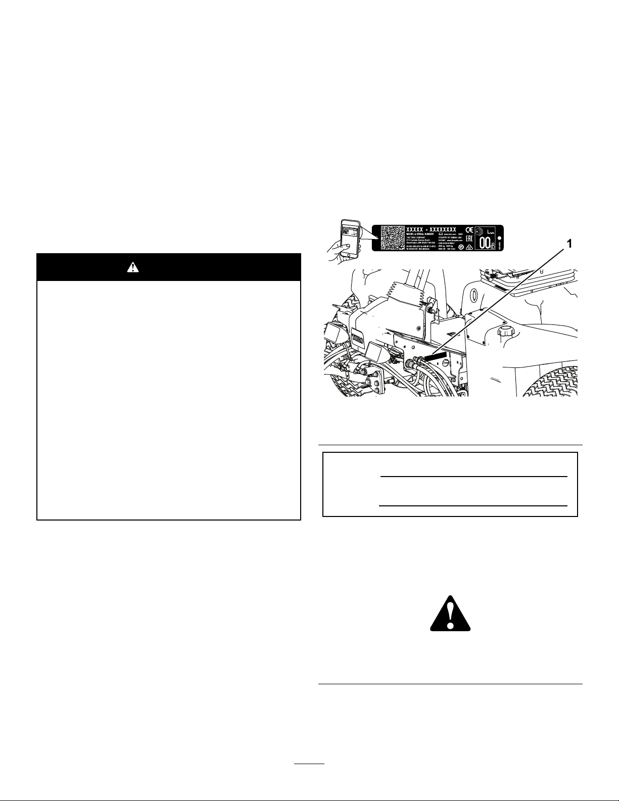
andserialnumbersofyourproductready.Figure1
identiesthelocationofthemodelandserialnumbers
ontheproduct.Writethenumbersinthespace
provided.
Important:Withyourmobiledevice,youcan
scantheQRcodeontheserialnumberplate(if
equipped)toaccesswarranty,parts,andother
productinformation.
g259591
Figure1
1.Modelandserialnumberlocation
Useofthisproductmaycauseexposure
tochemicalsknowntotheStateof
Californiatocausecancer,birthdefects,
orotherreproductiveharm.
Introduction
Thismachineisaride-on,reel-bladelawnmower
intendedtobeusedbyprofessional,hiredoperators
incommercialapplications.Itisprimarilydesigned
forcuttinggrassonwell-maintainedturf.Usingthis
productforpurposesotherthanitsintendedusecould
provedangeroustoyouandbystanders.
Readthisinformationcarefullytolearnhowtooperate
andmaintainyourproductproperlyandtoavoid
injuryandproductdamage.Youareresponsiblefor
operatingtheproductproperlyandsafely .
ModelNo.
SerialNo.
Thismanualidentiespotentialhazardsandhas
safetymessagesidentiedbythesafety-alertsymbol
(Figure2),whichsignalsahazardthatmaycause
seriousinjuryordeathifyoudonotfollowthe
recommendedprecautions.
g000502
Figure2
Safety-alertsymbol
Thismanualuses2wordstohighlightinformation.
Importantcallsattentiontospecialmechanical
informationandNoteemphasizesgeneralinformation
worthyofspecialattention.
©2020—TheToro®Company
8111LyndaleAvenueSouth
Bloomington,MN55420
Contactusatwww.Toro.com.
2
PrintedintheUSA
AllRightsReserved
Page 3

Contents
Safety.......................................................................4
GeneralSafety...................................................4
SafetyandInstructionalDecals..........................4
Setup........................................................................9
1AdjustingtheTirePressure............................10
2AdjustingtheControl-ArmPosition.................10
3InstallingtheCuttingUnits..............................10
4MountingtheFinishingKits............................13
5AdjustingtheTurf-Compensation
Spring...........................................................14
6InstallingtheCEHoodLatch..........................15
7UsingtheCutting-UnitKickstand....................16
8ApplyingtheCEDecals.................................16
ProductOverview...................................................17
Controls...........................................................17
Specications..................................................24
Attachments/Accessories.................................24
BeforeOperation.................................................24
BeforeOperationSafety...................................24
PerformingDailyMaintenance..........................25
FillingtheFuelTank..........................................25
BreakingintheMachine...................................25
BleedingtheFuelSystem.................................25
DuringOperation.................................................26
DuringOperationSafety...................................26
StartingtheEngine...........................................28
ShuttingOfftheEngine.....................................28
SettingtheReelSpeed.....................................29
AdjustingtheLift-ArmCounterbalance.............30
AdjustingtheLift-ArmTurnaround
Position.........................................................30
UnderstandingtheDiagnosticLight..................30
CheckingtheInterlockSwitches.......................31
OperatingTips.................................................31
AfterOperation....................................................31
AfterOperationSafety......................................31
PushingorT owingtheMachine........................32
IdentifyingtheTie-DownPoints........................32
JackingPoints..................................................33
HaulingtheMachine.........................................33
Maintenance...........................................................34
MaintenanceSafety..........................................34
RecommendedMaintenanceSchedule(s)...........34
DailyMaintenanceChecklist.............................36
Lubrication..........................................................37
GreasingtheBearingsandBushings................37
EngineMaintenance...........................................39
EngineSafety...................................................39
ServicingtheAirCleaner..................................39
CheckingtheEngine-OilLevel..........................40
ServicingtheEngineOilandFilter....................40
FuelSystemMaintenance...................................41
DrainingtheFuelT ank......................................41
CheckingtheFuelLinesand
Connections..................................................41
ServicingtheWaterSeparator..........................41
ServicingtheFuel-PickupTube........................42
BleedingAirfromtheFuelInjectors...................42
ElectricalSystemMaintenance...........................43
ElectricalSystemSafety...................................43
ServicingtheBattery.........................................43
ReplacingtheFuses.........................................43
DriveSystemMaintenance..................................45
CheckingtheTirePressure...............................45
CheckingtheT orqueoftheWheel
Nuts..............................................................45
AdjustingtheTractionDriveforNeutral.............45
AdjustingtheRearWheelToe-in.......................45
CoolingSystemMaintenance..............................46
CoolingSystemSafety.....................................46
CheckingtheCoolingSystem...........................46
RemovingDebrisfromtheCooling
System..........................................................47
BrakeMaintenance.............................................48
AdjustingtheParkingBrakes............................48
AdjustingtheParking-BrakeLatch....................49
BeltMaintenance................................................49
TensioningtheAlternatorBelt...........................49
HydraulicSystemMaintenance...........................50
HydraulicSystemSafety...................................50
CheckingtheHydraulicLinesand
Hoses............................................................50
HydraulicFluidSpecication.............................50
CheckingtheLeveloftheHydraulic
Fluid..............................................................50
HydraulicFluidCapacity...................................51
ChangingtheHydraulicFluid............................51
ReplacingtheHydraulicFilter...........................52
TestingthePressureintheHydraulic
System..........................................................52
CuttingUnitSystemMaintenance........................53
BladeSafety.....................................................53
CheckingtheReel-to-BedknifeContact............53
BacklappingtheCuttingUnits...........................53
Storage...................................................................54
StorageSafety..................................................54
PreparingtheTractionUnit...............................54
PreparingtheEngine........................................54
3
Page 4

Safety
Thismachinehasbeendesignedinaccordance
withENISO5395(whenyoucompletethesetup
procedures)andANSIB71.4-2017.
•Donotoperatethemachinewithoutallguards
andothersafetyprotectivedevicesinplaceand
functioningproperlyonthemachine.
•Keepchildren,bystanders,andpetsoutofthe
operatingarea.Neverallowchildrentooperate
themachine.
GeneralSafety
Thisproductiscapableofamputatinghandsandfeet
andofthrowingobjects.
•Readandunderstandthecontentsofthis
Operator’sManualbeforestartingtheengine.
•Useyourfullattentionwhileoperatingthe
machine.Donotengageinanyactivitythat
causesdistractions;otherwise,injuryorproperty
damagemayoccur.
•Donotputyourhandsorfeetnearmoving
componentsofthemachine.
SafetyandInstructionalDecals
Safetydecalsandinstructionsareeasilyvisibletotheoperatorandarelocatednearanyarea
ofpotentialdanger.Replaceanydecalthatisdamagedormissing.
93-6689
•Shutofftheengine,removethekey,waitforall
movementtostopbeforeyouleavetheoperator’s
position.Allowthemachinetocoolbefore
adjusting,servicing,cleaning,orstoringit.
Improperlyusingormaintainingthismachinecan
resultininjury .Toreducethepotentialforinjury,
complywiththesesafetyinstructionsandalways
payattentiontothesafety-alertsymbol
meansCaution,Warning,orDanger—personalsafety
instruction.Failuretocomplywiththeseinstructions
mayresultinpersonalinjuryordeath.
decal93-6689
,which
1.Warning—donotcarrypassengers.
93–6696
1.Storedenergyhazard—readtheOperator'sManual.
93-7272
1.Cutting/dismembermenthazard;fan—stayawayfrom
movingparts.
decal106-6754
106-6754
1.Warning—donottouchthehotsurface.
2.Cutting/dismembermenthazard,fan;entanglementhazard,
belt—stayawayfrommovingparts.
decal93-6696
decal93-7272
decal106-6755
106-6755
1.Enginecoolantunder
pressure.
2.Explosionhazard—read
theOperator'sManual.
3.Warning—donottouchthe
hotsurface.
4.Warning—readthe
Operator'sManual.
4
Page 5
decalbatterysymbols
decal110-0986
110-0986
Someorallofthesesymbolsareonyourbattery .
BatterySymbols
1.Pressthebrakepedalandparkingbrakepedaltosetthe
parkingbrake.
2.Pressthebrakepedaltoapplythebrake.
3.Pressthetractionpedaltomovethemachineforward.
4.Reelenabledmode
5.Transportmode
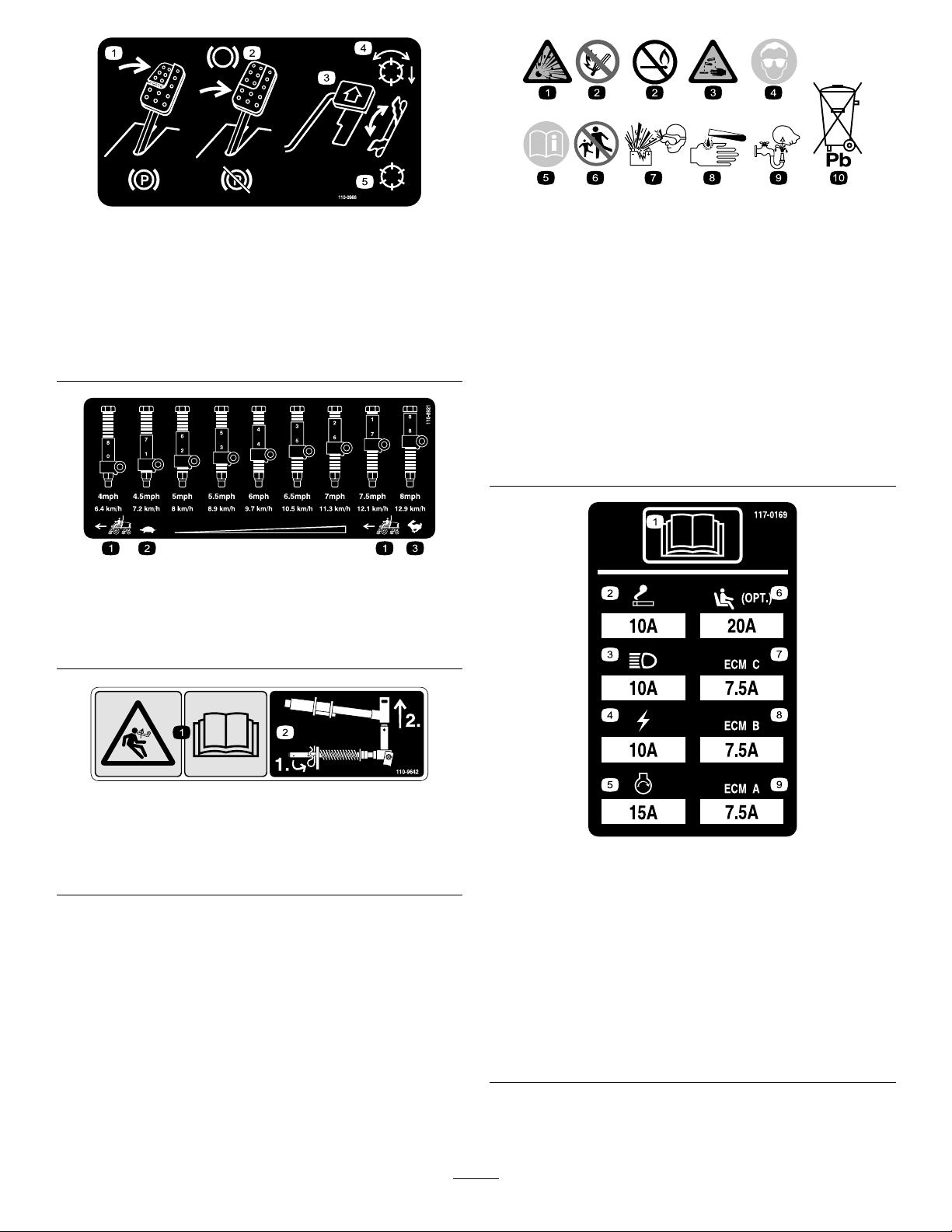
110-8921
1.Tractionunitspeed
2.Slow
3.Fast
1.Explosionhazard6.Keepbystandersaway
fromthebattery .
2.Nore,opename,or
smoking
7.Weareyeprotection;
explosivegasescan
causeblindnessandother
injuries.
3.Causticliquid/chemical
burnhazard
8.Batteryacidcancause
blindnessorsevereburns.
4.Weareyeprotection.9.Flusheyesimmediately
withwaterandgetmedical
helpfast.
5.ReadtheOperator's
Manual.
decal110-8921
10.Containslead;donot
discard
110-9642
1.Storedenergyhazard—readtheOperator'sManual.
2.Movethecotterpintotheholeclosesttotherodbracket
andthenremovetheliftarmandpivotyoke.
decal110-9642
r:\decal117-0169
117-0169
1.ReadtheOperator'sManual.
2.Lighter
3.Headlights
4.Electric
5.Enginestart
6.Airrideseatsuspension(optional)
7.EnginecomputermanagementC
8.EnginecomputermanagementB
9.EnginecomputermanagementA
5
Page 6

decal120-4158
120–4158
1.ReadtheOperator’s
Manual.
2.Engine—start4.Engine—stop
3.Engine—preheat
decal125-8754
125–8754
1.Headlights
2.Engage7.Lowerthecuttingunits
3.Powertake-off(PTO)
4.Disengage
5.Fast
6.Slow
8.Raisethecuttingunits
9.ReadtheOperator’s
Manual.
125-8818
1.Nore,openames,orsmoking.5.ReadtheOperator’sManual.
2.Weareyeprotection.6.Explosionhazard
3.Keepbystandersaway.
7.Containslead;donotdiscard.
4.Corrosiveliquidhazard8.ReadtheOperator’sManual;attention.
6
decal125-8818
Page 7

decal133-8062
decal127-2470
133-8062
127-2470
decal133-2930
133-2930
1.Warning—donotoperatethismachineunlessyouaretrained.4.Tippinghazard—driveslowlywhenturning;donotturnsharply
whiletravelingfast;onlydriveonslopeswiththecuttingunits
lowered;alwayswearaseatbelt.
2.Warning—wearhearingprotection.5.Warning—donotparkonslopes;engagetheparkingbrake,
lowerthecuttingunits,shutofftheengine,andremovethe
ignitionkeybeforeleavingthemachine.
3.Thrownobjecthazard—keepbystandersoutoftheoperating
area.
6.Warning—readtheOperator'sManual;donottowthe
machine.
7
Page 8

133-2931
Note:Thismachinecomplieswiththeindustrystandardstabilitytestinthestaticlateralandlongitudinaltestswiththemaximum
recommendedslopeindicatedonthedecal.ReviewtheinstructionsforoperatingthemachineonslopesintheOperator’sManualas
wellastheconditionsinwhichyouwouldoperatethemachinetodeterminewhetheryoucanoperatethemachineintheconditions
onthatdayandatthatsite.Changesintheterraincanresultinachangeinslopeoperationforthemachine.Ifpossible,keepthe
cuttingunitsloweredtothegroundwhileoperatingthemachineonslopes.Raisingthecuttingunitswhileoperatingonslopescan
causethemachinetobecomeunstable.
decal133-2931
1.Warning—readtheOperator'sManual;donotoperatethis
machineunlessyouaretrained.
4.Tippinghazard—donotdriveacrossordownslopesgreater
than15°;onlydriveonslopeswiththecuttingunitslowered;
alwayswearaseatbelt.
2.Warning—wearhearingprotection.5.Warning—donotparkonslopes;engagetheparkingbrake,
lowerthecuttingunits,shutofftheengine,andremovethe
ignitionkeybeforeleavingthemachine.
3.Thrownobjecthazard—keepbystandersaway .
6.Warning—readtheOperator'sManual;donottowthe
machine.
1.ReadtheOperator'sManual.
decal138-6975
138-6975
8
Page 9

Setup
LooseParts
Usethechartbelowtoverifythatallpartshavebeenshipped.
ProcedureDescription
1
2
3
4
5
6
7
8
MediaandAdditionalParts
Nopartsrequired
Nopartsrequired
Cuttingunits
Finishingkit(soldseparately)
Nopartsrequired
Hood-latchassembly1
Washer1
Cutting-unitkickstand
Warningdecal1
CEdecal
Productionyeardecal1
Qty.
–
–
5
1
–
1Installthecutting-unitkickstand.
1
Adjustthetirepressure.
Adjustthecontrol-armposition.
Installthecuttingunits.
Mountthenishingkits(nishingkits
aresoldseparately).
Adjusttheturf-compensationspring.
InstalltheCEhoodlatch.
ApplytheCEdecals.
Use
Description
Key2
Operator'sManual
Engineowner’smanual1
DeclarationofConformity
Operatortrainingmaterial
Qty.
Starttheengine.
1
1
1
ReadtheOperator'sManualbeforeoperatingthemachine.
Usethemanualtoreferenceengineinformation.
Declarationofconformity
Reviewthematerialbeforeoperatingthemachine.
Note:Determinetheleftandrightsidesofthemachinefromthenormaloperatingposition.
Use
9
Page 10

1
AdjustingtheTirePressure
NoPartsRequired
Procedure
Thetiresareover-inatedforshipping.Therefore,
releasesomeoftheairtoreducethepressure.
Correctairpressureinthefrontandreartiresis83
to103kPa(12to15psi).
Important:Maintainevenpressureinalltiresto
ensureuniformcontactwiththeturf.
2
g004152
Figure3
1.Controlarm3.Bolts(2)
2.Retainingbrackets
AdjustingtheControl-Arm
Position
NoPartsRequired
Procedure
Thecontrol-armpositioncanbeadjustedforyour
comfort.
1.Loosenthe2boltssecuringthecontrolarmto
theretainingbracket(Figure3).
2.Rotatethecontrolarmtothedesiredposition
andtightenthe2bolts.
3
InstallingtheCuttingUnits
Partsneededforthisprocedure:
5
Cuttingunits
Procedure
CAUTION
Ifyoudonotdisconnectthepowertothe
cuttingunits,someonecouldaccidentally
startthecuttingunit,causingseriousinjury
tohandsandfeet.
Alwaysseparatethepower-disconnect
connectorsbeforeworkingonthecutting
units(Figure28).
1.Disconnectthepower-disconnectconnector;
refertoCutting-Unit-PowerDisconnect(page
18).
2.Removethecuttingunitsfromthecartons.
Assembleandadjustasdescribedinthecutting
unitOperator'sManual.
10
Page 11

3.Makesurethatthecounterweight(Figure4)is
installedtotheproperendofthecuttingunitas
describedinthecounterweightkitInstallation
Instructions.
C.Mountthespring-tubebolttotheopposite
tabonthecarrierframeandsecurewiththe
angenut.
Note:Positiontotheboltheadtotheouter
sideofthetabasshowninFigure6.
g003967
Figure6
Figure4
1.Counterweight
4.Mounttheturf-compensationspringtothesame
sideofthecuttingunitasthereel-drivemotor.
Positiontheturfcompensationasfollows:
Note:Allcuttingunitsareshippedwiththe
turf-compensationspringmountedtotheright
sideofthecuttingunit.
A.Removethe2carriageboltsandnuts
securingtherodbrackettothecutting-unit
tabs(Figure5).
1.Oppositecarrier-frametab
2.Rodbracket
D.Mounttherodbrackettothecutting-unit
tabswiththecarriageboltsandnuts(Figure
6).
Note:Wheninstallingorremovingthe
cuttingunits,makesurethatthehairpin
cotterisinstalledinthespringrodholenext
g027133
5.Lowerallliftarmscompletely .
6.Removethelynchpinfromtheliftarmpivot
totherodbracket.Otherwise,installthe
hairpincotterintheholeintheendofthe
rod.
yoke.Then,removethecap(Figure7).
Figure5
1.Turf-compensationspring3.Springtube
2.Rodbracket
B.Removetheangenutsecuringthespring
tubebolttothecarrier-frametab(Figure5)
Removetheassembly.
g003975
Figure7
1.Lynchpin
g003949
2.Cap
7.Forthefrontcuttingunits,slideacuttingunit
undertheliftarmwhileinsertingthecarrier-frame
shaftupintothelift-arm-pivotyoke(Figure8).
11
Page 12

Note:Usethenumberofchainlinksdescribed
inthecuttingunitOperator'sManual.
Figure10
g003948
Figure8
1.Liftarm3.Lift-arm-pivotyoke
2.Carrier-frameshaft
8.Usethefollowingprocedureontherearcutting
unitswhentheheightofcutisabove19mm
(3/4inch).
A.Removethelynchpinandwashersecuring
thelift-arm-pivotshafttotheliftarmand
slidethelift-arm-pivotshaftoutofthelift
arm(Figure9).
Figure9
1.Lift-armchain
g003977
2.Chainbracket
3.Pin
12.Coatthesplineshaftofthereelmotorwithclean
grease.
13.OilthereelmotorO-ringandinstallitontothe
motorange.
14.Installthemotorbyrotatingitclockwisesothat
themotorangesclearthebolts(Figure11).
Note:Rotatethemotorcounterclockwiseuntil
theangesencircletheboltsandthentighten
thebolts.
Important:Makesurethatthereel-motor
hosesarenottwisted,kinked,oratriskof
beingpinched.
g003979
1.Lynchpinandwasher
B.Insertthelift-armyokeontothecarrier-frame
shaft(Figure8).
C.Insertthelift-armshaftintotheliftarmand
secureitwiththewasherandlynchpin
(Figure9).
9.Insertthecapoverthecarrier-frameshaftand
lift-armyoke.
10.Securethecapandthecarrier-frameshaftto
thelift-armyokewiththesnapperpin(Figure7).
Note:Usetheslotifasteeringcuttingunitis
desiredorusetheholeifthecuttingunitisto
belockedinposition.
11.Securethelift-armchaintothechainbracket
withthesnapperpin(Figure10).
12
Page 13

1.Reel-drivemotor
Figure11
2.Mountingbolt(2)
g316995
Figure12
1.Centerfrontcuttingunit4.Frontleftcuttingunit
2.Leftrearcuttingunit
3.Rightrearcuttingunit6.Reelmotorlocation
1.Onthefrontleftcorneroftheframe(#4cutting
unitlocation),removetheextraangenuton
theboltsecuringthebulkheadbrackettothe
machine(Figure13).
2.Loosenthenutsonthenishingkithosetting,
insertthehoseintotheslotonthebulkhead
bracketandtightenthenuts.
5.Frontrightcuttingunit
Note:Whentighteningthenuts,useabackup
g027140
wrenchtopreventthehosefromtwistingor
kinking.
3.Inserttheconnectorplateontothe
bulkhead-mountingboltswiththeconnectors
positionedasshowninFigure13.
4.Securetheconnectorplateto1ofthemounting
boltswiththeangenutpreviouslyremoved.
4
MountingtheFinishingKits
Partsneededforthisprocedure:
1
Finishingkit(soldseparately)
Procedure
Important:Toensurethatthehoseroutingis
appropriateandthehosesarenottwisted,mount
themotorstothecuttingunitsbeforemounting
thenishingkits.
Usethefollowingdiagramtodeterminethe
positionsofcuttingunitsandreelmotors.
5.Locatethewireharnessonthemachineand
plugthewireconnectorsintothewireconnectors
ofthenishingkit.
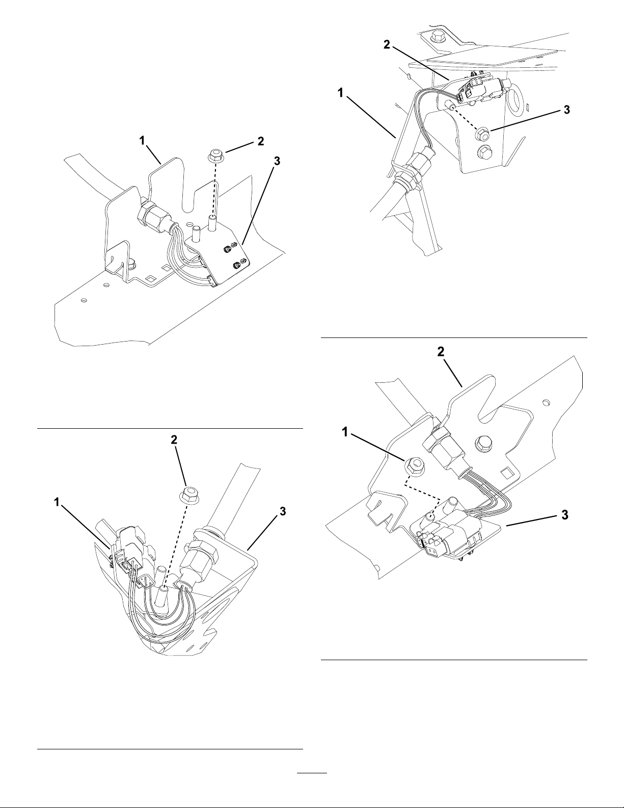
Figure13
Leftfrontcuttingunit(#4)
1.Extraangenut
2.Connectorplate
3.Bulkheadbracket
g316962
13
Page 14
6.Repeattheprocedureontheremaining4
bulkheadlocationsasshowninFigure14
throughFigure17.
Important:Theconnectorplatesare
positioneddifferentlyattheremaining
locationssothehosecanberoutedthrough
thebulkheadbracketandtothecuttingunit
withoutgettingtwistedorkinked.
g316996
Figure16
Rightfrontcuttingunitlocation(#5)
1.Bulkheadbracket
2.Extraangenut
Figure14
Leftrearcuttingunit(#2)
3.Connectorplate
1.Bulkheadbracket
2.Connectorplate
g316994
3.Extraangenut
g316998
Figure17
Rightrearcuttingunit(#3)
1.Connectorplate
2.Extraangenut
1.Extraangenut3.Connectorplate
2.Bulkheadbracket
g316976
Figure15
Centerfrontcuttingunit(#1)
(Undersideofmachineshown)
3.Bulkheadbracket
14
Page 15

5
6
Adjustingthe
Turf-CompensationSpring
NoPartsRequired
Procedure
Theturf-compensationspring(Figure18)transfers
theweightfromthefronttotherearroller.Thishelps
toreduceawavepatternintheturf,alsoknownas
marcellingorbobbing.
Important:Makespringadjustmentswiththe
cuttingunitmountedtothetractionunit,pointing
straightaheadandloweredtotheground.
1.Makesurethatthehairpincotterisinstalledin
therearholeinthespringrod(Figure18).
InstallingtheCEHood
Latch
Partsneededforthisprocedure:
1Hood-latchassembly
1Washer
Procedure
1.Unlatchandraisethehood.
2.Removetherubbergrommetfromtheholein
theleftsideofthehood(Figure19).
Figure18
1.Turf-compensationspring3.Springrod
2.Hairpincotter4.Hexnuts
2.Tightenthehexnutsonthefrontendofthe
springroduntilthecompressedlengthofthe
springis12.7cm(5inches)for5-inchcutting
unitsor15.9cm(6.25inches)for7-inchcutting
units(Figure18).
Note:Whenoperatingonroughterrain
decreasethespringlengthby12.7mm
(1/2inch).Groundfollowingwillbeslightly
decreased.
g027072
g003863
1.Rubbergrommet
3.Removethenutfromthehood-latchassembly
(Figure20).
1.Hoodlatch3.Rubberwasher
2.Nut4.Metalwasher
Figure19
g003946
Figure20
15
Page 16

4.Outsidethehood,insertthehookendofthe
latchthroughtheholeinthehood.Makesure
thattherubbersealingwasherremainsonthe
outsideofthehood.
5.Insidethehood,insertthemetalwasheronto
thelatchandsecurewiththenut.Makesure
thatthelatchengagestheframecatchwhenit
islocked.Usetheenclosedhood-latchkeyto
operatethehoodlatch.
7
UsingtheCutting-Unit
Kickstand
Partsneededforthisprocedure:
1
Cutting-unitkickstand
g004144
Figure22
1.Chainbracket3.Cutting-unitkickstand
2.Snapperpin
Procedure
Wheneveryouneedtotipthecuttingunittoexpose
thebedknife/reel,propuptherearofthecuttingunit
withthekickstandtomakesurethatthenutsonthe
backendofthebedbar-adjustingscrewsarenot
restingontheworksurface(Figure21).
Figure21
8
ApplyingtheCEDecals
Partsneededforthisprocedure:
1Warningdecal
1
CEdecal
1Productionyeardecal
Procedure
OnmachinesrequiringCEcompliance,applythe
productionyeardecal(PartNo.133-5615)nearthe
serialplate,theCEdecal(PartNo.93-7252)near
thehoodlock,andtheCEwarningdecal(PartNo.
133-2931)overthestandardwarningdecal(PartNo.
133-2930).
g003985
1.Cutting-unitkickstand
Securethekickstandtothechainbracketwiththe
snapperpin(Figure22).
16
Page 17

ProductOverview
1.Enginehood
2.Operator'sseat
3.Controlarm
4.Steeringwheel
Figure23
5.Seatadjustments
6.Frontcuttingunits
7.Rearcuttingunits
TractionPedal
Thetractionpedal(Figure25)controlstheforwardand
reverseoperation.Pressthetopofthepedaltomove
forwardandthebottomtomoverearward.Theground
speeddependsonhowfaryoupressthepedal.For
noload,maximumgroundspeed,fullypressthepedal
whilethethrottleisintheFASTposition.
Tostopthemachine,reducefootpressureonthe
tractionpedalandallowittoreturntothecenter
position.
Mow-SpeedLimiter
Whenthemow-speedlimiter(Figure25)isipped
upitcontrolsthemowspeedandallowsthecutting
unitstobeengaged.Eachspaceradjuststhemowing
speedby0.8km/h(0.5mph).Themorespacersyou
g260768
have,onthetopoftheboltthesloweryougo.For
transport,ipbackthemow-speedlimiterandyouwill
havemaximumtransportspeed.
Note:WhenmowingintheEconomymode,the
mowinggroundspeedisslightlyreduced.Remove1
spacertoachievethesamemowingspeedaswhen
mowinginthenormalmode.
Controls
Seat-AdjustingKnobs
Theseat-adjustinglever(Figure24)allowsyouto
adjusttheseatforeandaft.Theweight-adjusting
knobadjuststheseatforyourweight.Theweight
gaugeindicateswhentheseatisadjustedtoyour
weight.Theheight-adjustingknobadjuststheseat
foryourheight.
Figure24
BrakePedal
Pressthebrakepedal(Figure25)tostopthemachine.
ParkingBrake
Toengagetheparkingbrake,(Figure25)pushdown
onthebrakepedalandpressthetopforwardtolatch.
Toreleasetheparkingbrake,pressthebrakepedal
untiltheparking-brakelatchretracts.
g003954
1.Weightgauge3.Height-adjustingknob
2.Weight-adjustingknob
4.Adjustinglever(foreand
aft)
17
Page 18

KeySwitch
Thekeyswitch(Figure26)has3positions:OFF,
ON/PREHEAT,andSTART.
LowerMow/RaiseControlLever
Thislever(Figure26)raisesandlowersthecutting
unitsandalsostartsandstopsthecuttingunitswhen
thecuttingunitsareenabledintheMOWmode.Y ou
cannotlowerthecuttingunitswhenthemow/transport
leverisintheTRANSPORTposition.
HeadlightSwitch
Figure25
1.Tractionpedal4.Brakepedal
2.Mow-speedlimiter5.Parkingbrake
3.Spacers
6.Tilt-steeringpedal
Tilt-SteeringPedal
Totiltthesteeringwheeltowardyou,pressthefoot
pedal(Figure25)down,pullthesteeringtowertoward
youtothemostcomfortableposition,andthenrelease
thepedal.
Engine-SpeedSwitch
Theengine-speedswitchhas2modestochangethe
enginespeed(Figure26).Bymomentarilytappingthe
switch,youcanchangetheenginespeedin100rpm
increments.Ifyouholdtheswitchdown,theengine
automaticallymovestoHighorLowidle,depending
onwhichendoftheswitchyoupress.
g003955
(Figure26).
Enable/DisableSwitch
Pivottheswitchdownwardtoturnontheheadlights
Usetheenable/disableswitch(Figure26)in
conjunctionwiththelowermow/raisecontrolleverto
operatethecuttingunits.
PowerPoint
Thepowerpointisa12Vpowersupplyforelectronic
devices(Figure27).
Figure26
1.Lowermow/raisecontrol
lever
2.Keyswitch5.Engine-speedswitch
3.InfoCenter
4.Enable/disableswitch
6.Headlightswitch
g004133
Figure27
1.Powerpoint
g021208
Cutting-Unit-PowerDisconnect
Beforeinstalling,removing,orworkingonthecutting
units,disconnectthecuttingunitsfromthepower
supplybyseparatingthecutting-unit-power-disconnect
connector(Figure28),locatedundertheseat.Plug
theconnectorbackinbeforeoperatingthemachine.
18
Page 19

1.Power-disconnectconnector
Figure28
g020650
Figure29
1.Indicatorlight3.Middlebutton
2.Rightbutton
4.Leftbutton
•LeftButton,MenuAccess/BackButton—Press
thisbuttontoaccesstheInfoCentermenus.
Youcanuseittobackoutofanymenuyouare
currentlyusing.
g027134
•MiddleButton—Pressthisbuttontoscrolldown
menus.
•RightButton—Pressthisbuttontoopenamenu
wherearightarrowindicatesadditionalcontent.
CAUTION
Ifyoudonotdisconnectthepowertothe
cuttingunits,someonecouldaccidentally
startthecuttingunit,causingseriousinjury
tohandsandfeet.
Alwaysseparatethe
cutting-unit-power-disconnectconnectors
beforeworkingonthecuttingunits.
UsingtheInfoCenterLCDDisplay
TheInfoCenterLCDdisplayshowsinformationabout
yourmachinesuchastheoperatingstatus,various
diagnosticsandotherinformationaboutthemachine
(Figure29).Therearemultipledisplayscreensonthe
InfoCenter.Youcanswitchbetweenthescreens,at
anytime,bypressinganyoftheInfoCenterbuttons
andthenselectingtheappropriatedirectionalarrow.
Note:Thepurposeofeachbuttonmaychange
dependingonwhatisrequiredatthetime.Each
buttonislabeledwithanicondisplayingitscurrent
function.
19
Page 20

InfoCenterIconDescription
SERVICEDUE
Indicateswhenscheduledservice
shouldbeperformed
Hourmeter
Infoicon
Fast
InfoCenterIconDescription(cont'd.)
Battery
Motor/Generator(notcharging)
Motor/Generator(charging)
E-Reel
Slow
Fuellevel
Theglowplugsareactive.
Raisethecuttingunits.
Lowerthecuttingunits.
Sitintheseat.
Theparkingbrakeison.
Therangeishigh(transport).
Neutral
Therangeislow(mow).
FrontBacklap
RearBacklap
Thecuttingunitsarelowering.
Thecuttingunitsareraising.
PINpasscode
CANbus
InfoCenter
Badorfailed
Bulb
OutputofTECcontrollerorcontrol
wireinharness
Switch
Releasetheswitch.
Engine-coolanttemperature(°Cor
°F)
Temperature(hot)
ThePTOisengaged.
Notallowed
Starttheengine.
Stoptheengine.
Engine
Keyswitch
Changetotheindicatedstate.
Symbolsareoften
combinedtoform
sentences.Some
examplesareshown
below
PutthemachineintoNeutral.
Enginestartisdenied.
Engineshutdown
Enginecoolantistoohot.
Sitdownorsetparkingbrake
20
Page 21

UsingtheMenus
ToaccesstheInfoCentermenusystem,pressthe
menuaccessbuttonwhileatthemainscreen.This
bringsyoutothemainmenu.Refertothefollowing
tablesforasynopsisoftheoptionsavailablefrom
themenus:
MainMenu
MenuItemDescription
FaultsTheFaultsmenucontainsalist
ServiceTheServicemenucontains
DiagnosticsTheDiagnosticsmenu
SettingsTheSettingsmenuallows
AboutTheAboutmenuliststhe
Service
MenuItemDescription
Hours
Counts
Diagnostics
MenuItemDescription
CuttingUnitsIndicatestheinputs,qualiers,
Hi/LowRangeIndicatestheinputs,qualiers,
PTOIndicatestheinputs,qualiers,
oftherecentmachinefaults.
RefertotheServiceManualor
contactyourT oroDistributor
formoreinformationon
theFaultsmenuandthe
informationcontainedthere.
informationonthemachine
suchashoursofuse,counters,
andothersimilarnumbers.
displaysthestateofeach
machineswitch,sensor,and
controloutput.Y oucanuse
thistotroubleshootcertain
issuesasitquicklytellsyou
whichmachinecontrolsareon
andwhichareoff.
youtocustomizeandmodify
congurationvariablesonthe
InfoCenterdisplay.
modelnumber,serialnumber,
andsoftwareversionofyour
machine.
Liststhetotalnumberofhours
thatthemachine,engineand
PTOhavebeenon,aswell
asthenumberofhoursthe
machinehasbeentransported
andservicedue.
Listsnumerouscountsthe
machinehasexperienced.
andoutputsforraisingand
loweringthecuttingunits.
andoutputsfordrivingin
transportmode.
andoutputsforenablingthe
PTOcircuit.
EngineRun
Backlap
Settings
MenuItemDescription
Units
Language
LCDBacklightControlsthebrightnessofthe
LCDContrastControlsthecontrastofthe
FrontBacklapReelSpeedControlsthespeedofthefront
RearBacklapReelSpeedControlsthespeedoftherear
ProtectedMenusAllowsthe
AutoIdle
BladeCountControlsthenumberofblades
MowSpeedControlsthegroundspeedfor
Heightofcut(HOC)Controlstheheightofcut
FReelRPMDisplaysthecalculatedreel
RReelRPMDisplaysthecalculatedreel
EconomyModeWhenactivated,theEconomy
Indicatestheinputs,qualiers,
andoutputsforstartingthe
engine.
Indicatestheinputs,qualiers
andoutputsforoperatingthe
backlapfunction.
Controlstheunitsusedonthe
InfoCenter.Themenuchoices
areEnglishorMetric.
Controlsthelanguageused
ontheInfoCenter*.
LCDdisplay.
LCDdisplay.
reelsinbacklapmode.
reelsinbacklapmode.
superintendent/mechanic
toaccessprotectedmenusby
inputtingapasscode.
Controlstheamountoftime
allowedbeforereturningthe
enginetolowidlewhenthe
machineisstationary.
onthereelforreelspeed.
determiningthereelspeed.
(HOC)fordeterminingthereel
speed.
speedpositionforthefront
reels.Thereelscanalsobe
manuallyadjusted.
speedpositionfortherear
reels.Thereelscanalsobe
manuallyadjusted.
Modelowerstheengine
speedwhilemowingtoreduce
noiseandfuelconsumption.
Thereelspeeddoesnot
change,butthemowspeedis
decreasedifthemowstopis
notadjustedaccordingly.
*Only"operator-faced"textistranslated.Faults,
Service,andDiagnosticsscreensare"service-faced.”
Titlesareintheselectedlanguage,butmenuitems
areinEnglish.
21
Page 22

About
MenuItemDescription
Model
SNListstheserialnumberofthe
MachineControllerRevisionListsthesoftwarerevisionof
CU1
CU2
CU3
CU4
CU5
GeneratorListsthesoftwarerevisionof
InfoCenterRevisionListsthesoftwarerevisionof
CANBus
Liststhemodelnumberofthe
machine.
machine.
themastercontroller .
Liststhesoftwarerevisionof
eachcuttingunit.
themotor/generator.
theInfoCenter.
Liststhemachine
communicationbusstatus.
ProtectedMenus
Thereare2additionaldisplayscreensand7operating
congurationsettingsthatareadjustablewithinthe
SettingsMenuoftheInfoCenter:AutoIdle,Blade
Count,MowSpeed,HeightofCut(HOC),FReel
RPM,RReelRPM,andEconomyMode.These
settingscanbelockedbyusingtheProtectedMenu.
Note:Atthetimeofdelivery ,theinitialpassword
codeisprogrammedbyyourdistributor.
AccessingtheProtectedMenu
7.Pressthemiddlebuttontoenterthecode.
8.Ifthecodehasbeenacceptedandtheprotected
menuhasbeenunlocked,“PIN”isbedisplayed
intheupperrightcornerofthedisplayscreen.
Note:Ifthepasscodehasbeenforgottenor
misplaced,pleasecontactyourdistributorfor
assistance.
ViewingandChangingthe
ProtectedMenuSettings
1.IntheProtectedMenu,scrolldowntoProtect
Settings.
2.Toviewandchangethesettingswithoutentering
apasscode,usetherightbuttontochangethe
ProtectSettingstoOFF.
3.Toviewandchangethesettingswitha
passcode,usetheleftbuttontochangethe
ProtectSettingstoON,setthepasscode,and
turnthekeytotheOFFpositionandthentothe
ONposition.
SettingtheAutoIdle
1.IntheSettingsMenu,scrolldowntoAutoIdle.
2.Presstherightbuttontochangetheautoidle
timebetweenOFF,8S,10S,15S,20S,and30S.
SettingtheBladeCount
1.IntheSettingsMenu,scrolldowntoBladeCount
2.Presstherightbuttontochangethebladecount
between5,8or1 1bladereels.
SettingsandDisplayScreens
ToaccesstheProtectedMenuSettingsandDisplay
Screens
1.FromtheMainMenu,scrolldowntotheSettings
Menuandpresstherightbutton.
2.IntheSettingsMenu,scrolldowntothe
ProtectedMenuandpresstherightbutton.
3.Toenterthepasscode,usethecenterbuttonto
settherstdigitthenpresstherightbuttonto
moveontothenextdigit.
4.Usethecenterbuttontosettheseconddigit
thenpresstherightbuttontomoveontothe
nextdigit.
5.Usethecenterbuttontosetthethirddigitthen
presstherightbuttontomoveontothenext
digit.
6.Usethecenterbuttontosetthefourthdigitthen
presstherightbutton.
SettingtheMowSpeed
1.IntheSettingsMenu,scrolldowntoMowSpeed.
2.PresstherightbuttontoselectMowSpeed.
3.Usethecenterandrightbuttontoselectthe
appropriatemowspeedsetonthemechanical
mow-speedlimiteronthetractionpedal.
4.Presstheleftbuttontoexitmowspeedandsave
thesetting.
SettingtheHeightofCut(HOC)
1.IntheSettingsMenu,scrolldowntoHOC.
2.PresstherightbuttontoselectHOC.
3.Usethecenterandrightbuttontoselectthe
appropriateHOCsetting.(Iftheexactsettingis
notdisplayed,selectthenearestHOCsetting
fromthelistdisplayed).
4.PresstheleftbuttontoexitHOCandsavethe
setting.
22
Page 23

SettingtheFrontandRearReel
Speeds
Althoughthefrontandrearreelspeedsarecalculated
byinputtingthenumberofblades,mowspeedand
HOCintotheInfoCenter,thesettingcanbemanually
changedtoaccommodatefordifferentmowing
conditions.
1.TochangetheReelSpeedSettings,scrolldown
totheFReelRPM,RReelRPM,orboth.
2.Presstherightbuttontochangethereelspeed
value.Asthespeedsettingischanged,the
displaycontinuestoshowthecalculatedreel
speedbasedonbladecount,mowspeedand
HOCwhichwaspreviouslyentered,butthenew
valuealsoisdisplayed.
SettingtheEconomyMode
1.FromtheMainMenu,usethecenterbuttonto
scrolldowntotheSettingsMenu.
2.Presstherightbuttontoselect.
3.IntheSettingsMenu,usethecenterbuttonto
scrolldowntotheEconomyMode.
4.PresstherightbuttontoselecttheONfunction.
5.Presstheleftbuttontosavethesettingandexit
thesettings.
ToAccessProtectedDisplay
Screens
Fromthemainscreen,pressthecenterbuttononce,
whenthearrowsappearabovethebuttons,press
thecenterbuttonagaintoscrollthroughthedisplay
screens.
PressthecenterbuttonagaintoaccesstheeReel
informationscreendisplayingthereelcurrentandthe
speedforeachofthe5cuttingunits.
Pressthecenterbuttonagaintoaccesstheenergy
modescreendisplayingthecomponents,energyow
andthedirectionwhileinoperation.
23
Page 24

Specications
Note:Specicationsanddesignaresubjectto
changewithoutnotice.
TransportWidth
Widthofcut254cm(100inches)
Length
Heightw/ROPS160cm(63inches)
Weight
EngineKubota24.8hp
Fueltankcapacity
Transportspeed
Mowingspeed
Attachments/Accessories
AselectionofT oroapprovedattachmentsand
accessoriesisavailableforusewiththemachine
toenhanceandexpanditscapabilities.Contact
yourAuthorizedServiceDealerorauthorizedT oro
distributororgotowww.Toro.comforalistofall
approvedattachmentsandaccessories.
Toensureoptimumperformanceandcontinuedsafety
certicationofthemachine,useonlygenuineT oro
replacementpartsandaccessories.Replacement
partsandaccessoriesmadebyothermanufacturers
couldbedangerous,andsuchusecouldvoidthe
productwarranty.
228cm(90inches)
282cm(111inches)
1259kg(2,776lb)
53L(14USgallons)
0to16km/h(0to10mph)
0to13km/h(0to8mph)
Operation
Note:Determinetheleftandrightsidesofthe
machinefromthenormaloperatingposition.
BeforeOperation
BeforeOperationSafety
GeneralSafety
•Neverallowchildrenoruntrainedpeopleto
operateorservicethemachine.Localregulations
mayrestricttheageoftheoperator.Theowner
isresponsiblefortrainingalloperatorsand
mechanics.
•Becomefamiliarwiththesafeoperationofthe
equipment,operatorcontrols,andsafetysigns.
•Alwaysshutofftheengine,removethekey,wait
forallmovingpartstostop,andallowthemachine
tocoolbeforeadjusting,servicing,cleaning,or
storingthemachine.
•Knowhowtostopthemachineandshutoffthe
enginequickly.
•Donotoperatethemachinewithoutallguards
andothersafetyprotectivedevicesinplaceand
functioningproperlyonthemachine.
•Beforemowing,alwaysinspectthemachineto
ensurethatthecuttingunitsareingoodworking
condition.
•Inspecttheareawhereyouwillusethemachine
andremoveallobjectsthatthemachinecould
throw.
FuelSafety
•Useextremecareinhandlingfuel.Itisammable
anditsvaporsareexplosive.
•Extinguishallcigarettes,cigars,pipes,andother
sourcesofignition.
•Useonlyanapprovedfuelcontainer.
•Donotremovethefuelcaporllthefueltank
whiletheengineisrunningorhot.
•Donotaddordrainfuelinanenclosedspace.
•Donotstorethemachineorfuelcontainerwhere
thereisanopename,spark,orpilotlight,such
asonawaterheaterorotherappliance.
•Ifyouspillfuel,donotattempttostarttheengine;
avoidcreatinganysourceofignitionuntilthefuel
vaporshavedissipated.
24
Page 25

PerformingDaily
Maintenance
ServiceInterval:Beforeeachuseordaily
Beforestartingthemachineeachday ,performthe
EachUse/DailyprocedureslistedinMaintenance
(page34).
FillingtheFuelTank
FuelTankCapacity
53L(14USgallons)
FuelSpecication
AddingFuel
1.Parkthemachineonalevelsurface,lowerthe
cuttingunits,shutofftheengine,andremove
thekey .
2.Usingacleanrag,cleantheareaaroundthe
fuel-tankcap.
3.Removethecapfromthefueltank(Figure30).
Useonlyclean,freshdieselfuelorbiodieselfuelswith
low(<500ppm)orultralow(<15ppm)sulfurcontent.
Theminimumcetaneratingshouldbe40.Purchase
fuelinquantitiesthatcanbeusedwithin180days
toensurefuelfreshness.
Usesummergradedieselfuel(No.2-D)at
temperaturesabove-7°C(20°F)andwintergrade(No.
1-DorNo.1-D/2-Dblend)belowthattemperature.
Useofwintergradefuelatlowertemperatures
provideslowerashpointandcoldowcharacteristics
whicheasesstartingandreducesfuellterplugging.
Useofsummergradefuelabove-7°C(20°F)
contributestowardlongerfuelpumplifeandincreased
powercomparedtowintergradefuel.
Important:Donotusekeroseneorgasoline
insteadofdieselfuel.Failuretoobservethis
cautiondamagestheengine.
BiodieselReady
Thismachinecanalsouseabiodieselblendedfuel
ofuptoB20(20%biodiesel,80%petrodiesel).The
petrodieselportionshouldbeloworultralowsulfur.
Observethefollowingprecautions:
•Thebiodieselportionofthefuelmustmeet
specicationASTMD6751orEN14214.
•TheblendedfuelcompositionshouldmeetASTM
D975orEN590.
•Paintedsurfacesmaybedamagedbybiodiesel
blends.
•UseB5(biodieselcontentof5%)orlesserblends
incoldweather.
•Monitorseals,hoses,gasketsincontactwithfuel
astheymaybedegradedovertime.
•Fuellterpluggingmaybeexpectedforatime
afterconvertingtobiodieselblended.
•Contactyourdistributorifyouwishformore
informationonbiodiesel.
g021210
Figure30
1.Fuel-tankcap
4.Fillthetankuntilthelevelistothebottomofthe
llerneckwithdieselfuel.
5.Installfuel-tankcaptightlyafterllingtank.
Note:Ifpossible,llthefueltankaftereachuse.
Thisminimizespossiblebuildupofcondensation
insidethefueltank.
BreakingintheMachine
Toensureoptimumperformanceoftheparkingbrake
system,burnish(breakin)thebrakesbeforeuse.
Settheforwardtractionspeedto6.4km/h(4mph)
tomatchthereversetractionspeed(all8spacers
movedtothetopofthemow-speedcontrol).With
theengineathighidle,proceedforwardwiththe
mow-speed-controlstopengagedandridethebrake
for15seconds.Proceedbackwardatfullreverse
speedandridethebrakefor15seconds.Repeat
this5timeswaiting1minutebetweeneachforward
andreversecycletoavoidoverheatingthebrakes.
Anadjustmenttothebrakesmayberequiredafter
break-in;refertoAdjustingtheParkingBrakes(page
48).
BleedingtheFuelSystem
Youmustbleedthefuelsystembeforestartingthe
engineifanyofthefollowingsituationshaveoccurred:
•Initialstart-upofanewmachine.
•Enginehasceasedrunningduetolackoffuel.
•Maintenancehasbeenperformeduponfuel
systemcomponents;i.e.,lterreplaced,separator
serviced,etc.
25
Page 26

DANGER
Undercertainconditions,dieselfuelandfuel
vaporsarehighlyammableandexplosive.A
reorexplosionfromfuelcanburnyouand
othersandcancausepropertydamage.
•Useafunnelandllthefueltankoutdoors,
inanopenarea,whentheengineisoffand
iscold.Wipeupanyfuelthatspills.
•Donotllthefueltankcompletelyfull.
Addfueltothefueltankuntilthelevelis6
to13mm(1/4to1/2inch)belowthebottom
ofthellerneck.Thisemptyspaceinthe
tankallowsthefueltoexpand.
•Neversmokewhenhandlingfuel,andstay
awayfromanopenameorwherefuel
fumesmaybeignitedbyaspark.
•Storefuelinaclean,safety-approved
containerandkeepthecapinplace.
1.Parkthemachineonalevelsurfaceandensure
thatthefueltankisatleasthalffull.
2.Openthehood.
3.Opentheair-bleedscrewonthefuel-injection
pump(Figure31)witha12mmwrench.
Figure31
1.Bleedscrew
4.TurnthekeytotheONposition.Theelectricfuel
pumpbeginsoperation,therebyforcingairout
aroundtheairbleedscrew.Leavethekeyinthe
ONpositionuntilasolidstreamoffuelowsout
aroundthescrew.
5.TightenthescrewandturnthekeytotheOFF
position.
Note:Normally,theengineshouldstartafterthe
abovebleedingproceduresarefollowed.However,if
enginedoesnotstart,airmaybetrappedbetween
injectionpumpandinjectors;refertoBleedingAir
fromtheFuelInjectors(page42).
DuringOperation
DuringOperationSafety
GeneralSafety
•Theowner/operatorcanpreventandisresponsible
foraccidentsthatmaycausepersonalinjuryor
propertydamage.
•Wearappropriateclothing,includingeye
protection;longpants;substantial,slip-resistant
footwear;andhearingprotection.Tiebacklong
hairanddonotwearlooseclothingorloose
jewelry.
•Donotoperatethemachinewhileill,tired,or
undertheinuenceofalcoholordrugs.
•Useyourfullattentionwhileoperatingthe
machine.Donotengageinanyactivitythat
causesdistractions;otherwise,injuryorproperty
damagemayoccur.
•Beforeyoustarttheengine,ensurethatalldrives
areinneutral,theparkingbrakeisengaged,and
youareintheoperatingposition.
•Donotcarrypassengersonthemachineand
keepbystandersandpetsawayfromthemachine
duringoperation.
•Operatethemachineonlyingoodvisibilitytoavoid
holesorhiddenhazards.
•Avoidmowingonwetgrass.Reducedtraction
couldcausethemachinetoslide.
•Keepyourhandsandfeetawayfromthecutting
units.
•Lookbehindanddownbeforebackinguptobe
sureofaclearpath.
g003993
•Usecarewhenapproachingblindcorners,shrubs,
trees,orotherobjectsthatmayobscureyour
vision.
•Stopthecuttingunitswheneveryouarenot
mowing.
•Slowdownandusecautionwhenmakingturns
andcrossingroadsandsidewalkswiththe
machine.Alwaysyieldtheright-of-way.
•Neverrunanengineinanareawhereexhaust
gassesareenclosed.
•Neverleavearunningmachineunattended.
26
Page 27

•Beforeleavingtheoperatingposition(includingto
emptythecatchersortounclogthecuttingunits),
dothefollowing:
–Donotoperateamachineunderanyconditions
wheretraction,steering,orstabilityisin
question.
–Parkthemachineonlevelground.
–Disengagethecuttingunitsandlowerthe
attachments.
–Engagetheparkingbrake.
–Shutofftheengineandremovethekey .
–Waitforallmovingpartstostop.
•Operatethemachineonlyingoodvisibilityand
appropriateweatherconditions.Donotoperate
themachinewhenthereistheriskoflightning.
RolloverProtectionSystem
(ROPS)Safety
•DonotremoveanyoftheROPScomponentsfrom
themachine.
•Ensurethattheseatbeltisattachedandthatyou
canreleaseitquicklyinanemergency.
•Alwayswearyourseatbelt.
•Checkcarefullyforoverheadobstructionsanddo
notcontactthem.
–Removeormarkobstructionssuchasditches,
holes,ruts,bumps,rocks,orotherhidden
hazards.T allgrasscanhideobstructions.
Uneventerraincouldoverturnthemachine.
–Beawarethatoperatingthemachineonwet
grass,acrossslopes,ordownhillmaycause
themachinetolosetraction.
–Useextremecautionwhenoperating
themachineneardrop-offs,ditches,
embankments,waterhazards,orother
hazards.Themachinecouldsuddenlyrollover
ifawheelgoesovertheedgeortheedge
cavesin.Establishasafetyareabetweenthe
machineandanyhazard.
–Identifyhazardsatthebaseoftheslope.
Iftherearehazards,mowtheslopewitha
pedestrian-controlledmachine.
–Ifpossible,keepthecuttingunitsloweredto
thegroundwhileoperatingonslopes.Raising
thecuttingunitswhileoperatingonslopescan
causethemachinetobecomeunstable.
•KeeptheROPSinsafeoperatingconditionby
thoroughlyinspectingitperiodicallyfordamage
andkeepingallthemountingfastenerstight.
•ReplacealldamagedROPScomponents.Donot
repairoralterthem.
SlopeSafety
•Slopesareamajorfactorrelatedtolossofcontrol
androlloveraccidents,whichcanresultinsevere
injuryordeath.Y ouareresponsibleforsafeslope
operation.Operatingthemachineonanyslope
requiresextracaution.
•Evaluatethesiteconditionstodetermineifthe
slopeissafeformachineoperation,including
surveyingthesite.Alwaysusecommonsense
andgoodjudgmentwhenperformingthissurvey .
•Reviewtheslopeinstructions,listedbelow,for
operatingthemachineonslopes.Beforeyou
operatethemachine,reviewthesiteconditionsto
determinewhetheryoucanoperatethemachine
intheconditionsonthatdayandatthatsite.
Changesintheterraincanresultinachangein
slopeoperationforthemachine.
–Avoidstarting,stopping,orturningthemachine
onslopes.Avoidmakingsuddenchangesin
speedordirection.Maketurnsslowlyand
gradually.
27
Page 28

StartingtheEngine
Important:Youmustbleedthefuelsystembefore
startingtheengineifyouarestartingtheengine
forthersttime,theenginehasshutoffdueto
lackoffuel,oryouhaveperformedmaintenance
onthefuelsystem;refertoBleedingtheFuel
System(page25).
1.Sitontheseat,keepyourfootoffthetraction
pedalsothatitisinNEUTRAL,engagetheparking
brake,settheengine-speedswitchtotheFAST
position,andensurethattheEnable/Disable
switchisintheDISABLEposition.
2.TurnthekeytotheON/PREHEA Tposition.
Anautomatictimercontrolstheglowplug
preheatfor6seconds.
3.Afterpreheatingtheglowplugs,turnthekeyto
theSTARTposition.
Cranktheenginefornolongerthan15seconds.
Releasethekeywhentheenginestarts.If
additionalpreheatingisrequired,turnthekeyto
theOFFpositionandthentotheON/PREHEA T
position.Repeatthisprocessasrequired.
4.Runtheengineatlowidlespeeduntilitwarms
up.
ShuttingOfftheEngine
1.MoveallcontrolstoNEUTRAL,engagethe
parkingbrake,movethethrottletotheLOWIDLE
positionandallowtheenginetoreachlowidle
speed.
Important:Allowtheenginetoidlefor5
minutesbeforeshuttingitoffafterafull
loadoperation.Failuretodosomayleadto
troubleonaturbo-chargedengine.
2.TurnthekeytotheOFFpositionandremoveit
fromtheswitch.
28
Page 29

SettingtheReelSpeed
Toachieveaconsistent,highquality-of-cutandauniformaftercutappearance,itisimportantthatyousetthe
reelspeedtothepropersetting.Adjustthereelspeedasfollows:
1.IntheInfoCenter,underthesettingsmenu,enterthebladecount,mowspeed,andHOCtocalculate
theproperreelspeed.
2.Iffurtheradjustmentsarerequired,inthesettingsmenu,scrolldowntotheFReelRPM,RReelRPM,or
both.
3.Presstherightbuttontochangethereelspeedvalue.Asthespeedsettingischanged,thedisplay
continuestoshowthecalculatedreelspeedbasedonbladecount,mowspeed,andHOC,butthenew
valueisalsodisplayed.
Note:Thereelspeedmayneedtobeincreasedordecreasedtocompensateforvaryingturfconditions.
Figure32
5inch(127mm)ReelSpeedChart
Figure33
7inch(178mm)ReelSpeedChart
g031995
g031996
29
Page 30

AdjustingtheLift-Arm
Counterbalance
Youcanadjustthecounterbalanceontherear
cutting-unitliftarmstocompensatefordifferentturf
conditionsandtomaintainauniformheightofcutin
theroughconditionsorinareasofthatchbuildup.
Youcanadjusteachcounterbalancespringto1of
4settings.Eachincrementincreasesordecreases
counterbalanceonthecuttingunitby2.3kg(5lb).
Youcanpositionthespringsonthebacksideofthe
rstspringactuatortoremoveallcounterbalance
(fourthposition).
1.Parkthemachineonalevelsurface,lowerthe
cuttingunits,engagetheparkingbrake,shutoff
theengine,andremovethekey.
2.Insertatubeorsimilarobjectontothelong
springendandpivotitaroundthespringactuator
tothedesiredposition(Figure34).
CAUTION
Thespringsareundertensionandcould
causepersonalinjury.
turnaroundheightormovetheswitchupto
decreasethelift-armturnaroundheight(Figure
35).
g012154
Figure35
1.Switch2.Lift-armsensingdevice
4.Tightenthemountingscrews.
Usecautionwhenadjustingthesprings.
Figure34
1.Spring2.Springactuator
3.Repeattheprocedureontheotherspring.
AdjustingtheLift-Arm
TurnaroundPosition
1.Parkthemachineonalevelsurface,lowerthe
cuttingunits,engagetheparkingbrake,shutoff
theengine,andremovethekey.
2.Thelift-armswitchislocatedunderneaththe
hydraulictankbehindthefront,rightliftarm
(Figure35).
3.Loosentheswitch-mountingscrewsand
movetheswitchdowntoincreasethelift-arm
Understandingthe
DiagnosticLight
Themachineisequippedwithadiagnosticlight,which
indicatesifthemachinedetectsamalfunction.The
diagnosticlightislocatedontheInfoCenter,above
thedisplayscreen(Figure36).Whenthemachine
isfunctioningproperlyandthekeyswitchismoved
totheON/RUNposition,thediagnosticlightturnson
brieytoindicatethatthelightisworkingproperly.
Whenamachineadvisorymessageappears,thelight
illuminateswhenthemessageispresent.Whena
g019276
faultmessageappears,thelightblinksuntilthefault
isresolved.
g021272
Figure36
1.Diagnosticlight
30
Page 31

CheckingtheInterlock
OperatingTips
Switches
Thepurposeoftheinterlockswitchesistopreventthe
enginefromcrankingorstartingunlessthetraction
pedalisintheNEUTRALposition,theEnable/Disable
switchisintheDISABLEposition,andtheLower
Mow/RaisecontrolisintheNEUTRALposition.In
addition,theengineshouldstopwhenyoupress
thetractionpedalwhileyouareofftheseatorifthe
parkingbrakeisengaged.
CAUTION
Ifthesafety-interlockswitchesare
disconnectedordamaged,themachinecould
operateunexpectedly,causingpersonal
injury.
•Donottamperwiththeinterlockswitches.
•Checktheoperationoftheinterlock
switchesdailyandreplaceanydamaged
switchesbeforeoperatingthemachine.
VerifyingtheInterlock-Switch
Function
ServiceInterval:Beforeeachuseordaily
1.Parkthemachineonalevelsurface,lowerthe
cuttingunits,shutofftheengine,engagethe
parkingbrake,andremovethekey.
2.TurnthekeytotheONposition,butdonotstart
themachine.
3.Locatetheappropriateswitchfunctioninthe
diagnosticsmenuontheInfoCenter.
4.Individually,changeeachoftheswitchesfrom
opentoclosed(i.e.,sitonseat,engagetraction
pedal,etc.),andnotethattheappropriatestate
oftheswitchchanges.
Note:Repeatthisforallswitchesthatyoucan
changebyhand.
5.Ifaswitchisclosedandtheappropriate
indicatordoesnotchange,checkallwiringand
connectionstotheswitchand/orcheckthe
switcheswithanohmmeter.
BecomingFamiliarizedwiththe
Machine
Beforemowinggrass,practiceoperatingthemachine
inanopenarea.Startandshutofftheengine.
Operateinforwardandreverse.Lowerandraisethe
cuttingunitsandengageanddisengagethereels.
Whenyoufeelfamiliarwiththemachine,practice
operatingupanddownslopesatdifferentspeeds.
UnderstandingtheWarning
System
Ifawarninglightcomesonduringoperation,stopthe
machineimmediatelyandcorrecttheproblembefore
continuingoperation.Seriousdamagecouldoccurif
youoperatethemachinewithamalfunction.
Mowing
Starttheengineandmovetheengine-speedswitch
totheFASTposition.MovetheEnable/Disableswitch
totheENABLEpositionandusetheLowerMow/Raise
levertocontrolthecuttingunits(thefrontcuttingunits
aretimedtolowerbeforetherearcuttingunits).To
moveforwardandcutgrass,pressthetractionpedal
forward.
TransportingtheMachine
MovetheEnable/DisableswitchtotheDISABLE
positionandraisethecuttingunitstotheTRANSPORT
position.MovetheMow/Transportlevertothe
TRANSPORTposition.Becarefulwhendrivingbetween
objectssoyoudonotaccidentallydamagethe
machineorcuttingunits.Useextracarewhen
operatingthemachineonslopes.Driveslowlyand
avoidsharpturnsonslopestopreventrollovers.
Lowerthecuttingunitswhengoingdownhillfor
steeringcontrol.
AfterOperation
AfterOperationSafety
Note:Replaceanyfaultyswitchesandrepair
anyfaultywiring.
Note:TheInfoCenterdisplayalsohastheabilityto
detectwhichoutputsolenoidsorrelaysareturned
on.Thisisaquickwaytodetermineifamachine
malfunctioniselectricalorhydraulic.
GeneralSafety
•Shutofftheengine,removethekey,andwait
forallmovementtostopbeforeyouleavethe
operator’sposition.Allowthemachinetocool
beforeadjusting,servicing,cleaning,orstoringit.
•Cleangrassanddebrisfromthecuttingunits,
drives,mufers,coolingscreens,andengine
31
Page 32

compartmenttohelppreventres.Cleanupoilor
fuelspills.
•Disengagethedrivetotheattachmentwhenever
youarehaulingornotusingthemachine.
•Maintainandcleantheseatbelt(s)asnecessary.
•Donotstorethemachineorfuelcontainerwhere
thereisanopename,spark,orpilotlight,such
asonawaterheateroronotherappliances.
PushingorTowingthe
Machine
Inanemergency ,youcanmovethemachine
byactuatingthebypassvalveinthevariable
displacementhydraulicpumpandpushingortowing
themachine.
Important:Donotpushortowthemachinefaster
than3to4.8km/h(2to3mph)becauseinternal
transmissiondamagemayoccur.Thebypass
valvemustbeopenwheneveryoupushortow
themachine.
1.Rotatethebypass-valvebolt1-1/2turnstoopen
andallowoiltobypassinternally(Figure37).
IdentifyingtheTie-Down
Points
•Front—theholeintherectangularpad,underthe
axletube,insideeachfronttire(Figure38)
g031851
Figure38
1.Fronttie-down
Note:Thebypassvalveislocatedontheleft
sideofthehydrostat.Bybypassingtheuid,you
canmovethemachineslowlywithoutdamaging
thetransmission.
Figure37
1.Bypass-valvebolt
2.Closethebypassvalvebeforestartingthe
engine.However,donotexceed7to1 1N∙m(5
to8ft-lb)torquetoclosethevalve.
•Rear—eachsideofthemachineontherearframe
(Figure39)
g003995
g027077
Figure39
1.Reartie-down
Important:Runningtheenginewiththe
bypassvalveopencausesthetransmission
tooverheat.
32
Page 33

JackingPoints
Note:Usejackstandstosupportthemachinewhen
required.
•Front—rectangularpad,undertheaxletube,
insideeachfronttire(Figure40).
Figure40
1.Frontjackingpoint
•Rear—rectangularaxletubeontherearaxle.
HaulingtheMachine
•Usefull-widthrampsforloadingthemachineonto
atrailerortruck.
•Tiethemachinedownsecurely.
g031850
33
Page 34

Maintenance
Note:Determinetheleftandrightsidesofthemachinefromthenormaloperatingposition.
MaintenanceSafety
•Beforeadjusting,cleaning,servicing,orleaving
themachine,dothefollowing:
–Parkthemachineonalevelsurface.
–Movethethrottleswitchtothelow-idleposition.
–Disengagethecuttingunits.
–Lowerthecuttingunits.
–Ensurethatthetractionisinneutral.
–Engagetheparkingbrake.
–Shutofftheengineandremovethekey .
–Waitforallmovingpartstostop.
–Allowmachinecomponentstocoolbefore
performingmaintenance.
RecommendedMaintenanceSchedule(s)
MaintenanceService
Interval
Afterthersthour
MaintenanceProcedure
•T orquethewheellugnutsto94to122N∙m(70to90ft-lb).
•Ifpossible,donotperformmaintenancewhilethe
engineisrunning.Keepawayfrommovingparts.
•Usejackstandstosupportthemachineor
componentswhenrequired.
•Carefullyreleasepressurefromcomponentswith
storedenergy.
•Keepallpartsofthemachineingoodworking
conditionandallhardwaretightened.
•Replaceallwornordamageddecals.
•Toensuresafe,optimalperformanceofthe
machine,useonlygenuineT ororeplacement
parts.Replacementpartsmadebyother
manufacturerscouldbedangerous,andsuchuse
couldvoidtheproductwarranty .
Aftertherst8hours
Aftertherst10hours
Aftertherst50hours
Beforeeachuseordaily
Every50hours
Every100hours
Every150hours
•Checktheconditionandtensionofthealternatorbelt.
•T orquethewheellugnutsto94to122N∙m(70to90ft-lb).
•Changetheengineoilandlter.
•Checktheenginespeed(idleandfullthrottle).
•Inspecttheseatbelt(s)forwear,cuts,andotherdamage.Replacetheseatbelt(s)if
anycomponentdoesnotoperateproperly.
•Checktheoperationoftheinterlockswitches.
•Checktheengine-oillevel.
•Drainwaterorothercontaminantsfromthewaterseparator.
•Checkthetirepressure.
•Checkthecoolingsystem.
•Removedebrisfromthescreen,oilcoolers,andradiator.(Morefrequentlyindirty
operatingconditions).
•Checkthehydrauliclinesandhoses.
•Checkthelevelofthehydraulicuid.
•Checkthereeltobedknifecontact.
•Greasethebearingsandbushings(andimmediatelyaftereverywashing).
•Cleanthebatteryandchecktheconditionofit(orweekly,whichevercomesrst).
•Checkthebattery-cableconnections.
•Inspectthecoolingsystemhoses.
•Checktheconditionandtensionofthealternatorbelt.
•Changetheengineoilandlter.
Every200hours
Every250hours
•Drainmoisturefromthefuelandhydraulicuidtanks.
•T orquethewheellugnutsto94to122N∙m(70to90ft-lb).
34
Page 35

MaintenanceService
Every400hours
Every800hours
Interval
MaintenanceProcedure
•Servicetheaircleaner.Servicetheaircleanerearlieriftheserviceindicatorshows
red.Serviceitmorefrequentlyinextremelydirtyordustyconditions.
•Checkthefuellinesandconnectionsfordeterioration,damage,orloose
connections.(Oryearly,whichevercomesrst).
•Replacethefuel-ltercanister.
•Checktheenginespeed(idleandfullthrottle).
•Drainandcleanthefueltank.
•Checktherearwheeltoe-in.
•Ifyouarenotusingtherecommendedhydraulicuidorhaveeverlledthereservoir
withanalternativeuid,changethehydraulicuid.
•Ifyouarenotusingtherecommendedhydraulicuidorhaveeverlledthereservoir
withanalternativeuid,replacethehydrauliclters.
•Packtherearwheelbearings(2wheeldrivemachinesonly).
•Adjusttheenginevalves(refertotheengineowner’smanual).
Every1,000hours
Every2,000hours
Beforestorage
Every2years
•Ifyouareusingtherecommendedhydraulicuid,replacethehydrauliclters.
•Ifyouareusingtherecommendedhydraulicuid,changethehydraulicuid.
•Drainandcleanthefueltank.
•Flushandreplacethecoolingsystemuid.
•Replaceallmovinghoses.
35
Page 36

DailyMaintenanceChecklist
Duplicatethispageforroutineuse.
Maintenance
CheckItem
Checkthe
safetyinterlock
operation.
Checkthebrake
operation.
Checkthelevels
oftheengineoil
andfuel.
Checkthe
cooling-system
uidlevel.
Drainthe
water/fuel
separator.
Checkthe
air-lterservice
indicator.
Checkthe
radiator,oil
cooler,and
screenfordebris.
Checkfor
unusualengine
1
noises.
Checkfor
unusual
operatingnoises.
Checktheuid
levelofthe
hydraulicsystem.
Checkthe
hydraulichoses
fordamage.
Checkforuid
leaks.
Checkthetire
pressure.
Checkthe
instrument
operation.
Checkthe
reel-to-bedknife
adjustment.
Checkthe
height-of-cut
adjustment.
Lubricateall
greasettings.
Touch-up
damagedpaint.
1.Checktheglowplugandinjectornozzlesiftheenginestartshard,producesexcesssmoke,orrunsrough.
2.Immediatelyaftereverywashing,regardlessoftheintervallisted
Fortheweekof:
Mon.Tues.Wed.Thurs.Fri.
2
Sat.Sun.
36
Page 37

NotationforAreasofConcern
Inspectionperformedby:
ItemDate
1
2
3
4
5
6
7
8
Information
Important:Refertoyourengineowner’smanualandcuttingunitOperator'sManualforadditional
maintenanceprocedures.
Note:T oobtainanelectricalschematicorahydraulicschematicforyourmachine,visitwww.Toro.com.
Lubrication
GreasingtheBearingsand
Bushings
ServiceInterval:Every50hours(andimmediately
aftereverywashing).
Lubricateallgreasettingsforthebearingsand
bushingswithNo.2lithiumgrease.
Thegreasettinglocationsandquantitiesareas
follows:
•PumpdriveshaftU-joint(3)(Figure41)
Figure41
(Shownwiththemotor/generatorcoverremoved)
•Cutting-unitlift-armcylinders(2each)(Figure42)
g012150
Figure42
•Lift-armpivots(1each)(Figure42)
•Cutting-unitcarrier-frameandpivot(2each)
(Figure43)
g027142
g003960
Figure43
•Lift-arm-pivotshaft(1each)(Figure44)
37
Page 38

Figure44
g004157
•Rearaxletierod(2)(Figure45)
Figure45
•Axle-steeringpivot(1)(Figure46)
g003966
Figure47
•Brakepedal(1)(Figure48)
g011615
Figure48
g003987
Figure46
•Steering-cylinderballjoints(2)(Figure47)
g004169
38
Page 39

EngineMaintenance
removelargeaccumulationsofdebrispacked
betweenoutsideofthelterandthecanister.
EngineSafety
•Shutofftheenginebeforecheckingtheoilor
addingoiltothecrankcase.
•Donotchangethegovernorspeedoroverspeed
theengine.
ServicingtheAirCleaner
ServiceInterval:Every400hours—Servicetheair
cleaner.Servicetheaircleaner
earlieriftheserviceindicatorshows
red.Serviceitmorefrequentlyin
extremelydirtyordustyconditions.
Checktheair-cleanerbodyfordamagewhichcould
causeanairleak.Replaceifdamaged.Checkthe
wholeintakesystemforleaks,damage,orloosehose
clamps.
Servicetheair-cleanerlteronlywhentheservice
indicatorrequiresit(Figure49).Changingtheairlter
beforeitisnecessaryonlyincreasesthechanceof
dirtenteringtheenginewhenyouremovethelter.
Important:Makesurethatthecoverisseated
correctlyandsealswiththeair-cleanerbody.
1.Parkthemachineonalevelsurface,lowerthe
cuttingunits,engagetheparkingbrake,shutoff
theengine,andremovethekey.
2.Releasethelatchessecuringtheair-cleaner
covertotheair-cleanerbody(Figure49).
Important:Avoidusinghigh-pressureair,
whichcouldforcedirtthroughthelterinto
theintaketract.
Note:Thiscleaningprocesspreventsdebris
frommigratingintotheintakewhenyouremove
thelter.
5.Removeandreplacethelter(Figure50).
Note:Donotcleantheusedelementduetothe
possibilityofdamagingtheltermedia.
g027080
Figure50
1.Air-cleanercover
2.Air-cleanerlter
3.Air-cleanerindicator
6.Inspectthenewlterforshippingdamage,
checkingthesealingendofthelterandthe
body.
Figure49
1.Air-cleanercover3.Air-cleanerservice
indicator
2.Air-cleaner-coverlatch
3.Removethecoverfromtheair-cleanerbody .
4.Beforeremovingthelter,uselow-pressure
air—275kPa(40psi),cleananddry—tohelp
Important:Donotuseadamagedelement.
7.Insertthenewlterbyapplyingpressuretothe
outerrimoftheelementtoseatitinthecanister.
Important:Donotapplypressuretothe
exiblecenterofthelter.
8.Cleanthedirt-ejectionportlocatedinthe
removablecover.Removetherubberoutlet
valvefromthecover,cleanthecavity,and
replacetheoutletvalve.
9.Installthecoverorientingtherubberoutletvalve
g027079
inadownwardposition—betweenapproximately
5o’clockto7o’clockwhenviewedfromtheend.
10.Securethelatches.
39
Page 40

CheckingtheEngine-Oil
Level
ServiceInterval:Beforeeachuseordaily
Theengineisshippedwithoilinthecrankcase;
however,theoillevelmustbecheckedbeforeand
aftertheengineisrststarted.
Crankcasecapacityisapproximately3.3L(3.5US
qt)withthelter.
Usehigh-qualityengineoilthatmeetsthefollowing
specications:
•APIClassicationLevelRequired:CH-4,CI-4or
higher
•Preferredoil:SAE15W-40(above0°F)
•Alternateoil:SAE10W-30or5W-30(all
temperatures)
ToroPremiumEngineoilisavailablefromyour
distributorineither15W-40or10W-30viscosity.
1.Parkthemachineonalevelsurface,lowerthe
cuttingunits,shutofftheengine,andremove
thekey .
5.IftheoillevelisbelowtheFULLmark,remove
thellcap(Figure52),andaddoiluntillevel
reachestheFULLmarkonthedipstick.
g004134
Figure52
1.Oil-llcap
2.Openthehood.
3.Removethedipstick,wipeitclean,andinstall
it(Figure51).
Figure51
Donotoverll.
Important:Makesurethatyoukeepthe
engine-oillevelbetweentheupperandlower
limitsontheoilgauge.Enginefailuremay
occurasaresultofoverllingorunder
llingtheengineoil.
6.Installtheoil-llcapandclosethehood.
ServicingtheEngineOil
andFilter
ServiceInterval:Aftertherst50hours—Change
theengineoilandlter.
Every150hours
1.Removethedrainplug(Figure53)andletthe
oilowintoadrainpan.
g027076
1.Dipstick
4.Removethedipstickandchecktheoillevelon
thedipstick.
Note:TheoillevelshouldbeuptotheFULL
mark.
40
Page 41

Figure53
1.Oil-drainplug
2.Whenalltheoilisdrained,installthedrainplug.
3.Removetheoillter(Figure54).
FuelSystem
Maintenance
DANGER
Undercertainconditions,fuelandfuelvapors
arehighlyammableandexplosive.Areor
explosionfromfuelcanburnyouandothers
andcancausepropertydamage.
•Fillthefueltankoutdoors,inanopenarea,
g003970
whentheengineisoffandiscold.Wipeup
anyfuelthatspills.
•Donotllthefueltankcompletelyfull.Add
fueltothefueltankuntilthelevelis25mm
(1inch)belowthetopofthetank,notthe
llerneck.Thisemptyspaceinthetank
allowsthefueltoexpand.
•Neversmokewhenhandlingfuel,andstay
awayfromanopenameorwherefuel
fumesmaybeignitedbyaspark.
•Storefuelinaclean,safety-approved
containerandkeepthecapinplace.
Figure54
1.Oillter
4.Applyalightcoatofcleanoiltothenewlter
seal.
5.Installthereplacementoilltertothelter
adapter.Turntheoillterclockwiseuntilthe
rubbergasketcontactsthelteradapter,then
tightenthelteranadditional1/2turn.
Important:Donotover-tightenthelter.
6.Addoiltothecrankcase;refertoCheckingthe
Engine-OilLevel(page40).
DrainingtheFuelTank
ServiceInterval:Every800hours
Beforestorage
Drainandcleanthefueltankifthefuelsystem
becomescontaminatedorifthemachineistobe
storedforanextendedperiod.Usecleanfueltoush
outthetank.
CheckingtheFuelLines
g003971
andConnections
ServiceInterval:Every400hours(Oryearly,
whichevercomesrst).
Inspectthefuellinesfordeterioration,damage,or
looseconnections.
ServicingtheWater
Separator
ServiceInterval:Beforeeachuseordaily—Drain
waterorothercontaminantsfrom
thewaterseparator.
Every400hours
1.Placeacleancontainerunderthefuellter.
2.Loosenthedrainplugonthebottomofthelter
canister.
41
Page 42

Figure55
1.Water-separator-ltercanister
3.Cleantheareawheretheltercanistermounts.
4.Removetheltercanisterandcleanthe
mountingsurface.
5.Lubricatethegasketontheltercanisterwith
cleanoil.
6.Installtheltercanisterbyhanduntilthegasket
contactsthemountingsurface,thenrotateitan
additional1/2turn.
BleedingAirfromtheFuel
Injectors
Note:Performthisprocedureonlyifthefuelsystem
hasbeenpurgedofairthroughnormalpriming
proceduresandtheenginedoesnotstart;referto
BleedingtheFuelSystem(page25).
1.LoosenthepipeconnectiontotheNo.1nozzle
andholderassembly(Figure56).
g007367
g027141
Figure56
7.Tightenthedrainplugonthebottomofthelter
canister.
ServicingtheFuel-Pickup
Tube
Thefuel-pickuptube,locatedinsidethefueltank,
comeswithascreentohelppreventdebrisfrom
enteringthefuelsystem.Removethefuel-pickuptube
andcleanthescreenasrequired.
1.Fuelinjectors
2.TurnthekeytotheONpositionandwatchthe
fuelowaroundtheconnector.Whenyou
observeasolidowoffuel,turnthekeytothe
OFFposition.
3.Tightenthepipeconnectorsecurely .
4.Repeatsteps1through3ontheremaining
nozzles.
42
Page 43

ElectricalSystem
ReplacingtheFuses
Maintenance
Important:Beforeweldingonthemachine,
disconnectallcablesfromthebattery,bothwire
harnessplugsfromtheelectroniccontrolmodule,
andtheterminalconnectorfromthealternatorto
preventdamagetotheelectricalsystem.
ElectricalSystemSafety
•Disconnectthebatterybeforerepairingthe
machine.Disconnectthenegativeterminalrst
andthepositivelast.Connectthepositiveterminal
rstandthenegativelast.
•Chargethebatteryinanopen,well-ventilated
area,awayfromsparksandames.Unplugthe
chargerbeforeconnectingordisconnectingthe
battery.Wearprotectiveclothinganduseinsulated
tools.
ServicingtheBattery
ServiceInterval:Every50hours—Cleanthebattery
andchecktheconditionofit(or
weekly,whichevercomesrst).
Thereare8fusesinthe12Velectricalsystem.
Thefuseblock(Figure57)islocatedbehindthe
control-arm-accesspanel.
g003988
Figure57
1.Fuseblock
Every50hours—Checkthebattery-cable
connections.
DANGER
Batteryelectrolytecontainssulfuricacid,
whichisfatalifconsumedandcausessevere
burns.
•Donotdrinkelectrolyteandavoidcontact
withskin,eyes,orclothing.Wearsafety
glassestoshieldyoureyesandrubber
glovestoprotectyourhands.
•Fillthebatterywherecleanwaterisalways
availableforushingtheskin.
WARNING
Chargingthebatteryproducesgassesthat
canexplode.
Neversmokenearthebatteryandkeepsparks
andamesawayfromit.
decal117-0169
Figure58
Thereare6fusesinthe48Velectricalsystem.5
fusesarelocatedinthefuseblock(Figure59)which
isunderthehoodandbehindtheseat.Thesixthfuse
(Figure60)islocatedundertheblackcoverwhichis
undertheseat.
Keeptheterminalsandtheentirebatterycaseclean
becauseadirtybatterydischargesslowly .Toclean
thebattery,washtheentirecasewithasolutionof
bakingsodaandwater.Rinseitwithclearwater.
43
Page 44

Figure59
1.Fuse-blockcover2.Fuseblock
decal127-2470
Figure61
g027135
g027136
Figure60
1.Fuse
44
Page 45

DriveSystem
Maintenance
CheckingtheTirePressure
ServiceInterval:Beforeeachuseordaily
Checkthetirepressure.Thecorrectairpressurein
thefrontandreartiresis83to103kPa(12to15psi).
DANGER
Lowtirepressuredecreasesmachinesidehill
stability.Thiscouldcausearollover,which
mayresultinpersonalinjuryordeath.
Donotunder-inatethetires.
CheckingtheTorqueofthe
WheelNuts
ServiceInterval:Afterthersthour
Aftertherst10hours
Every250hours
Torquethewheelnutsto94to122N∙m(70to90ft-lb).
WARNING
Failuretomaintainpropertorqueofthewheel
nutscouldresultinpersonalinjury.
Maintainthepropertorqueonthewheelnuts.
AdjustingtheTraction
DriveforNeutral
Themachinemustnotcreepwhenyoureleasethe
tractionpedal.Ifitdoescreep,adjustitasfollows:
g004147
Figure62
1.Locknut2.Traction-adjustmentcam
WARNING
Theenginemustberunningwhileyou
performthenaladjustmentonthe
tractionadjustmentcam.Thiscould
causepersonalinjury.
Keepyourhands,feet,face,andother
bodypartsawayfromthemufer,other
hotpartsoftheengine,andanyrotating
parts.
4.Starttheengineandrotatethecamhexineither
directionuntilthewheelsstoprotating.
5.Tightenthelocknuttosecuretheadjustment.
6.Shutofftheengine,removethejackstands,and
lowerthemachinetotheground.
7.Testdrivethemachinetomakesurethatitdoes
notcreep.
1.Parkthemachineonalevelsurface,lowerthe
cuttingunitstotheground,shutofftheengine,
andremovethekey.
2.Jackupthefrontofthemachineuntilthefront
tiresareofftheground.Supportthemachine
withjackstandstopreventitfromfalling
accidentally.
Note:On4-wheel-drivemodels,thereartires
mustalsobeofftheground.
3.Ontherightsideofthehydrostat,loosenthe
locknutonthetraction-adjustmentcam(Figure
62).
AdjustingtheRearWheel
Toe-in
ServiceInterval:Every800hours—Checktherear
wheeltoe-in.
1.Rotatethesteeringwheeltopositiontherear
wheelsstraightahead.
2.Loosenthejamnutoneachendofthetierod
(Figure63).
Note:Theendofthetierodwiththeexternal
grooveisaleft-handthread.
45
Page 46

Figure63
1.Jamnut3.Wrenchslot
2.Tierod
3.Usingthewrenchslot,rotatethetierod.
4.Measurethedistanceatthefrontandrearofthe
rearwheelsataxleheight.
CoolingSystem
Maintenance
CoolingSystemSafety
•Swallowingenginecoolantcancausepoisoning;
keepoutofreachfromchildrenandpets.
•Dischargeofhot,pressurizedcoolantortouching
ahotradiatorandsurroundingpartscancause
severeburns.
–Alwaysallowtheenginetocoolatleast15
g004136
CheckingtheCooling
System
ServiceInterval:Beforeeachuseordaily
minutesbeforeremovingtheradiatorcap.
–Usearagwhenopeningtheradiatorcap,and
openthecapslowlytoallowsteamtoescape.
Note:Thedistanceatthefrontoftherear
wheelsshouldbelessthan6mm(1/4inch)of
thedistancemeasuredattherearofthewheels.
5.Repeatthisprocedureasrequired.
Cleandebrisoffthescreen,oilcooler,andfrontof
theradiatordailyandmoreoftenifconditionsare
extremelydustyanddirty .RefertoRemovingDebris
fromtheCoolingSystem(page47).
Thecoolingsystemislledwitha50/50solution
ofwaterandpermanentethyleneglycolantifreeze.
Checkthelevelofcoolantintheexpansiontankatthe
beginningofeachdaybeforestartingtheengine.The
capacityofthecoolingsystemis5.2L(5.5USqt).
CAUTION
Iftheenginehasbeenrunning,the
pressurized,hotcoolantcanescapeand
causeburns.
•Donotopentheradiatorcapwhenthe
engineisrunning.
•Usearagwhenopeningtheradiatorcap,
andopenthecapslowlytoallowsteamto
escape.
1.Checkthelevelofcoolantintheexpansiontank
(Figure64).
Thecoolantlevelshouldbebetweenthemarks
onthesideofthetank.
46
Page 47

Figure64
g003951
Figure65
g004138
1.Expansiontank
2.Ifthecoolantlevelislow,removetheexpansion
tankcapandreplenishthesystem.Donot
overll.
3.Installtheexpansion-tankcap.
RemovingDebrisfromthe
CoolingSystem
ServiceInterval:Beforeeachuseordaily(More
frequentlyindirtyoperating
conditions).
Every100hours—Inspectthecoolingsystem
hoses.
Every2years—Flushandreplacethecooling
systemuid.
1.Parkthemachineonalevelsurface,lowerthe
cuttingunits,shutofftheengine,engagethe
parkingbrake,andremovethekey.
1.Rear-screenlatch2.Rearscreen
4.Cleanthescreenthoroughlywithcompressed
air.
5.Pivotthelatchesinwardtoreleasetheoilcooler
(Figure66).
2.Thoroughlycleanalldebrisoutoftheengine
area.
3.Unlatchtheclampandpivotopentherear
screen(Figure65).
g003974
Figure66
1.Oilcooler2.Oil-coolerlatches
6.Thoroughlycleanbothsidesoftheoilcoolerand
theradiator(Figure67)withcompressedair.
47
Page 48

Figure67
1.Radiator
7.Pivottheoilcoolerbackintopositionandsecure
thelatches.
8.Closethescreenandsecurethelatch.
BrakeMaintenance
AdjustingtheParking
Brakes
Adjustthebrakeswhenthereismorethan25mm(1
inch)offreetravel(Figure68)ofthebrakepedal,or
whenmoreholdingforceisrequired.Freetravelisthe
distancethatthebrakepedalmovesbeforeyoufeel
brakingresistance.
g004137
g026816
Figure68
1.Freetravel
Note:Usethewheelmotorbacklashtorockthe
drumsbackandforthtoensurethatthedrumsare
freepriortoandafteradjustment.
1.Toreducefreetravelofthebrakepedals,tighten
thebrakesbylooseningthefrontnutonthe
threadedendofthebrakecable(Figure69).
Figure69
1.Brakecables2.Frontnuts
2.Tightentherearnuttomovethecablebackward
untilbrakepedalshave6.3to12.7mm(1/4to
1/2inch)offreetravel(Figure68),beforethe
wheellocksup.
g011616
3.Tightenthefrontnuts,ensuringthatbothcables
actuatethebrakessimultaneously.
48
Page 49
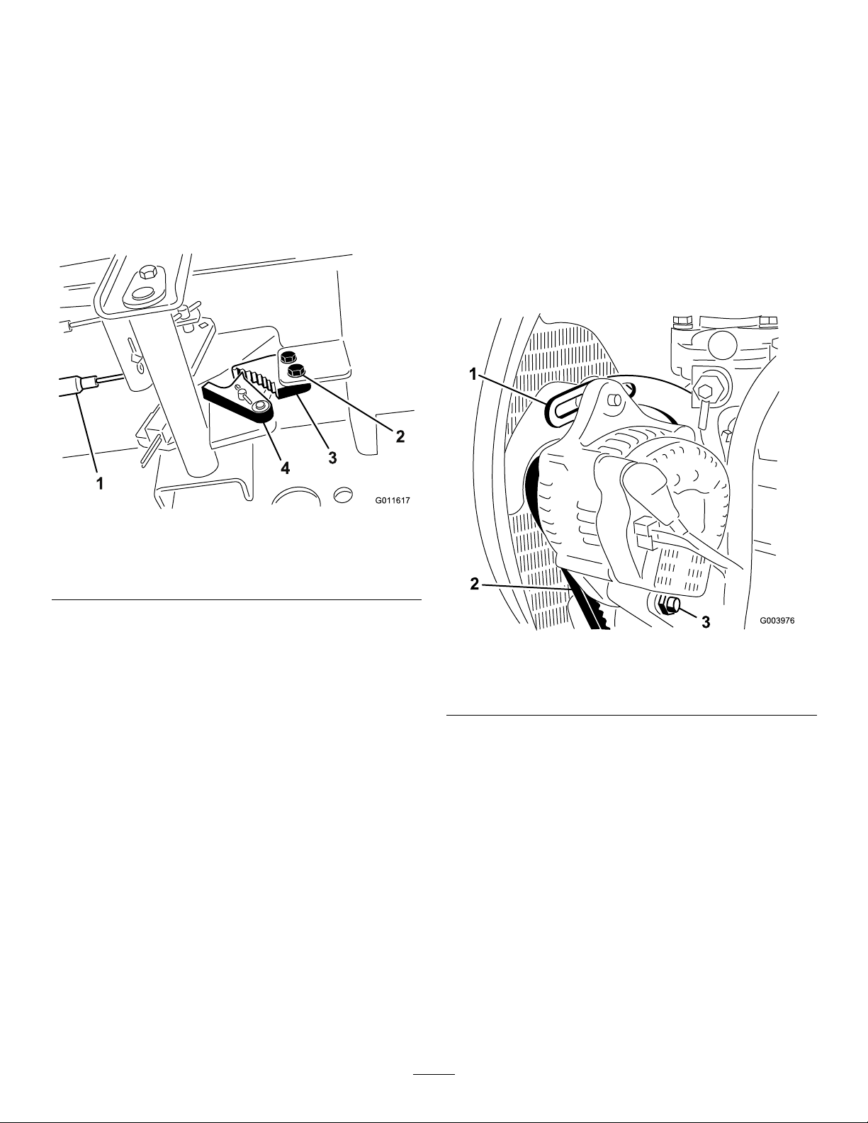
Note:Ensurethatthecableconduitdoesnot
rotatewhileyouaretighteningthenuts.
BeltMaintenance
Adjustingthe
Parking-BrakeLatch
Iftheparkingbrakefailstoengageandlatch,an
adjustmenttothebrakepawlisrequired.
1.Loosenthe2screwssecuringtheparking-brake
pawltotheframe(Figure70).
Figure70
TensioningtheAlternator
Belt
ServiceInterval:Aftertherst8hours
Every100hours
1.Openthehood.
2.Checkthetensionofthealternatorbeltby
depressingit(Figure71)midwaybetweenthe
alternatorandthecrankshaftpulleyswith10kg
(22lb)offorce.
g011617
1.Brakecables3.Parking-brakepawl
2.Screws(2)
2.Presstheparking-brakepedalforwarduntilthe
brakedetentcompletelyengagesonthebrake
pawl(Figure70).
3.Tightenthe2screwstolocktheadjustment.
4.Pressthebrakepedaltoreleasetheparking
brake.
5.Checktheadjustmentandadjustasrequired.
4.Brakedetent
g003976
Figure71
1.Brace3.Pivotbolt
2.Alternatorbelt
Thebeltshoulddeect11mm(7/16inch).If
thedeectionisincorrect,proceedtostep3.If
correct,continueoperation.
3.Loosentheboltsecuringthebracetotheengine
(Figure71),theboltsecuringthealternatorto
thebraceandthepivotbolt.
4.Insertaprybarbetweenthealternatorandthe
engineandpryoutonthealternator.
5.Whenyouachievethepropertension,tighten
thealternator,brace,andpivotboltstosecure
theadjustment.
49
Page 50

HydraulicSystem
Consultwithyourlubricantdistributortoidentifya
satisfactoryproduct.
Maintenance
HydraulicSystemSafety
•Seekimmediatemedicalattentionifuidisinjected
intoskin.Injecteduidmustbesurgicallyremoved
withinafewhoursbyadoctor.
•Ensurethatallhydraulic-uidhosesandlinesare
ingoodconditionandallhydraulicconnections
andttingsaretightbeforeapplyingpressureto
thehydraulicsystem.
•Keepyourbodyandhandsawayfrompinhole
leaksornozzlesthatejecthigh-pressurehydraulic
uid.
•Usecardboardorpapertondhydraulicleaks.
•Safelyrelieveallpressureinthehydraulicsystem
beforeperforminganyworkonthehydraulic
system.
CheckingtheHydraulic
LinesandHoses
ServiceInterval:Beforeeachuseordaily
Checkthehydrauliclinesandhosesforleaks,kinked
lines,loosemountingsupports,wear,loosettings,
weatherdeterioration,andchemicaldeterioration.
Makeallnecessaryrepairsbeforeoperating.
HydraulicFluid
Specication
Thereservoirislledatthefactorywithhigh-quality
hydraulicuid.Checkthelevelofthehydraulicuid
beforeyourststarttheengineanddailythereafter;
refertoCheckingtheLeveloftheHydraulicFluid
(page50).
Recommendedhydraulicuid:T oroPXExtended
LifeHydraulicFluid;availablein19L(5USgallon)
pailsor208L(55USgallon)drums.
Note:Amachineusingtherecommended
replacementuidrequireslessfrequentuidandlter
changes.
Alternativehydraulicuids:IfToroPXExtended
LifeHydraulicFluidisnotavailable,youmayuse
anotherconventional,petroleum-basedhydraulicuid
havingspecicationsthatfallwithinthelistedrange
forallthefollowingmaterialpropertiesandthatit
meetsindustrystandards.Donotusesyntheticuid.
Note:T orodoesnotassumeresponsibilityfor
damagecausedbyimpropersubstitutions,souse
productsonlyfromreputablemanufacturerswhowill
standbehindtheirrecommendation.
HighViscosityIndex/LowPourPoint
Anti-wearHydraulicFluid,ISOVG46
MaterialProperties:
Viscosity,ASTMD445cSt@40°C(104°F)
ViscosityIndexASTMD2270
PourPoint,ASTMD97-37°Cto-45°C(-34°F
IndustrySpecications:EatonVickers694(I-286-S,
M-2950-S/35VQ25or
44to48
140orhigher
to-49°F)
M-2952-S)
Note:Manyhydraulicuidsarealmostcolorless,
makingitdifculttospotleaks.Areddyeadditivefor
thehydraulicuidisavailablein20ml(0.67oz)
bottles.Abottleissufcientfor15to22L(4to6US
gallons)ofhydraulicuid.OrderPartNo.44-2500
fromyourauthorizedTorodistributor.
Important:ToroPremiumSynthetic
BiodegradableHydraulicFluidistheonly
syntheticbiodegradableuidapprovedbyToro.
Thisuidiscompatiblewiththeelastomersused
inTorohydraulicsystemsandissuitablefora
wide-rangeoftemperatureconditions.Thisuidis
compatiblewithconventionalmineraloils,butfor
maximumbiodegradabilityandperformance,the
hydraulicsystemshouldbethoroughlyushed
ofconventionaluid.ToroPremiumSynthetic
BiodegradableHydraulicFluidisavailablefrom
yourauthorizedT orodistributorin19L(5US
gallons)pailsor208L(55USgallons)drums.
CheckingtheLevelofthe
HydraulicFluid
ServiceInterval:Beforeeachuseordaily
1.Parkthemachineonalevelsurface,lowerthe
cuttingunits,shutofftheengine,engagethe
parkingbrake,andremovethekey.
2.Cleantheareaaroundthellerneckandcapof
thehydraulictank(Figure72).
50
Page 51

1.Hydraulic-tankcap
2.Raisethehood.
3.Placealargedrainpanunderthettingsecured
tothebottomofthehydraulic-uidreservoir
(Figure73).
g021215
Figure72
3.Removethecap/dipstickfromthellerneckand
wipeitwithacleanrag.
4.Insertthedipstickintothellerneck;then
removeitandcheckthelevelofuid.
Note:Theuidlevelshouldbewithinthe
operatingrangeonthedipstick.
Important:Donotoverll.
5.Iflevelislow,addappropriateuidtoraisethe
leveltotheFULLmark.
6.Installthecap/dipstickontothellerneck.
HydraulicFluidCapacity
41.6L(11USgallons);refertoHydraulicFluid
Specication(page50)
ChangingtheHydraulic
Fluid
ServiceInterval:Every2,000hours—Ifyou
areusingtherecommended
hydraulicuid,changethe
hydraulicuid.
Every800hours—Ifyouarenotusingthe
recommendedhydraulicuidorhaveever
lledthereservoirwithanalternativeuid,
changethehydraulicuid.
g027137
Figure73
1.Hose
4.Disconnectthehosefromthebottomofthe
ttingandletthehydraulicuidowintothe
drainpan.
5.Installthehosewhenhydraulicuidstops
draining.
6.Fillthereservoirwithhydraulicuid;referto
HydraulicFluidSpecication(page50)and
HydraulicFluidCapacity(page51).
Important:Useonlyhydraulicuids
specied.Otheruidscoulddamagethe
system.
7.Installthereservoircap.
8.Starttheengineanduseallofthehydraulic
controlstodistributehydraulicuidthroughout
thesystem.
9.Checkforleaks.
10.Shutofftheengine.
11.Checkthelevelofthehydraulicuidandadd
enoughtoraiseleveltotheFULLmarkonthe
dipstick.
Important:Donotoverllthereservoir.
Ifuidbecomescontaminated,contactyour
authorizedT oroDistributorbecausethesystemmust
beushed.Contaminateduidlooksmilkyorblack
whencomparedtocleanoil.
1.Parkthemachineonalevelsurface,lowerthe
cuttingunits,shutofftheengine,engagethe
parkingbrake,andremovethekey.
51
Page 52

ReplacingtheHydraulic
TestingthePressureinthe
Filter
ServiceInterval:Every1,000hours—Ifyou
areusingtherecommended
hydraulicuid,replacethe
hydrauliclters.
Every800hours—Ifyouarenotusingthe
recommendedhydraulicuidorhaveever
lledthereservoirwithanalternativeuid,
replacethehydrauliclters.
Important:Useofanyotherltersmayvoidthe
warrantyonsomecomponents.
1.Parkthemachineonalevelsurface,lowerthe
cuttingunits,shutofftheengine,engagethe
parkingbrake,andremovethekey.
2.Cleantheareaaroundthelter-mountingarea
andplaceadrainpanunderthelter(Figure74).
HydraulicSystem
Usethehydraulicsystemtestportstotestthe
pressureinthehydrauliccircuits.ContactyourToro
Distributorforassistance.
Usethetestportsonthefronthydraulictubes(Figure
75)toassistintroubleshootingthetractioncircuit.
Figure74
1.Hydrauliclter
3.Removethelter.
4.Lubricatethegasketonthenewlterwith
hydraulicoil.
5.Ensurethatthelter-mountingareaisclean.
6.Installthelterbyhanduntilthegasketcontacts
themountingsurface,thenrotateitanadditional
1/2turn.
7.Starttheengineandletitrunforabout2minutes
topurgeairfromthesystem.
8.Shutofftheengineandcheckforleaks.
g031993
Figure75
1.Traction-circuittestport
Usethetestportonthegearpump(Figure76)to
assistintroubleshootingtheliftcircuit.
g027138
g027139
Figure76
1.Lift-circuittestport2.Charge-pressurecircuit
52
Page 53

Usethetestportonthehydraulictube(Figure76)to
assistintroubleshootingthecharge-pressurecircuit.
CuttingUnitSystem
Maintenance
BladeSafety
•Awornordamagedbladeorbedknifecanbreak,
andapiececouldbethrowntowardyouor
bystanders,resultinginseriouspersonalinjuryor
death.
•Inspectthecuttingunitsperiodicallyforexcessive
wearordamage.
•Usecarewhencheckingthecuttingunits.Wrap
thebladesorweargloves,andusecautionwhen
servicingthereelsandbedknives.Onlyreplaceor
sharpenthereelsandbedknives;neverstraighten
orweldthem.
•Onmachineswithmultiplecuttingunits,takecare
whenrotatingareel;itcancausethereelsinthe
othercuttingunitstorotate.
Checkingthe
Reel-to-BedknifeContact
ServiceInterval:Beforeeachuseordaily
Eachdaybeforeoperating,checkthereel-to-bedknife
contact,regardlessifthequalityofcuthadpreviously
beenacceptable.Theremustbelightcontactacross
thefulllengthofthereelandthebedknife(referto
AdjustingtheReeltoBedknifeinthecuttingunit
Operator'sManual).
BacklappingtheCutting
Units
Note:Whenbacklapping,thefrontunitsalloperate
together,andtherearunitsoperatetogether.
1.Parkthemachineonalevelsurface,lowerthe
cuttingunits,shutofftheengine,engagethe
parkingbrake,andmovetheEnable/Disable
switchtoDISABLEposition.
2.Toactivatethebacklapfunctiononthe
InfoCenterservicemenu,proceedasfollows:
A.Withtheengineoff,butthekeyintherun
position,accesstheMainMenuofthe
InfoCenter.
B.FromtheMainMenu,scrolldowntoService
Menuusingthecenterbuttonandselectit
usingtherightbutton.
C.IntheServiceMenu,scrolldowntoFront
Backlap,RearBacklap,andactivatefront,
rearorbothbyusingtherightbuttontoturn
53
Page 54

thedesiredsetofcuttingunitsfromOFFto
ON.
D.Presstheleftbuttontosavethesettings
andexittheSettingsmenu.
3.Makeinitialreel-to-bedknifeadjustments
appropriateforbacklappingonallcuttingunits
whicharetobebacklapped;refertothecutting
unitOperator'sManual.
4.Starttheengineandrunatlowidlespeed.
DANGER
Changingtheenginespeedwhile
backlappingmaycausethereelstostall.
•Neverchangetheenginespeedwhile
backlapping.
•Onlybacklapatidleenginespeed.
Storage
StorageSafety
•Shutofftheengine,removethekey,waitforall
movementtostopbeforeyouleavetheoperator’s
position.Allowthemachinetocoolbefore
adjusting,servicing,cleaning,orstoringit.
•Donotstorethemachineorfuelcontainerwhere
thereisanopename,spark,orpilotlight,such
asonawaterheateroronotherappliances.
PreparingtheTractionUnit
1.Parkthemachineonalevelsurface,lowerthe
cuttingunits,engagetheparkingbrake,shutoff
theengine,andremovethekey.
5.WiththeMow/TransportleverintheMOW
position,movetheEnable/Disableswitchto
theENABLEposition.MovetheLowerMow/Lift
controlforwardtostartthebacklappingoperation
onthedesignatedreels.
6.Applylappingcompoundwithalong-handled
brush.
Important:Neveruseashort-handled
brush.
7.Ifthereelsstallorbecomeerraticwhile
backlapping,selectahigherreelspeedsetting
untilthespeedstabilizes,thenreturnthereel
speedtoyourdesiredspeed.Thiscanbedone
usingthebuttonsontheInfoCenter.
8.Tomakeanadjustmenttothecuttingunits
whilebacklapping,turnthereelsoffbymoving
theLowerMow/Raiseleverrearward;the
Enable/DisableswitchtotheDISABLEposition,
andshutofftheengine.Aftercompleting
adjustments,repeatstepsthrough.
9.Repeattheprocedureforallcuttingunitsyou
wanttobacklap.
10.Whennished,turnoffthebacklapfunctions,
usingthebuttonsintheInfoCenter,andwashall
lappingcompoundoffthecuttingunits.Adjust
cuttingunitreeltobedknifeasneeded.Adjust
thecuttingunitreelspeedtothedesiredmowing
setting.
Important:Ifyoudonotreturnthebacklap
functiontotheOFFsettingafterbacklapping,
thecuttingunitsdonotraiseorfunction
properly.
Note:Burrsorroughedgesmayresultfrom
lappingthecuttingedge.Forabettercutting
edge,leacrossthecuttingedge90ºtothefront
faceofthebedknifetoremovetheburrs.
2.Thoroughlycleanthetractionunit,cuttingunits,
andtheengine.
3.Checkthetirepressure;refertoCheckingthe
TirePressure(page45).
4.Checkallfastenersforlooseness;tightenthem
asnecessary.
5.Greaseoroilallgreasettingsandpivotpoints.
Wipeupanyexcesslubricant.
6.Lightlysandandusetouch-uppaintonpainted
areasthatarescratched,chipped,orrusted.
Repairanydentsinthemetalbody.
7.Servicethebatteryandcablesasfollows;refer
toElectricalSystemSafety(page43):
A.Removethebatteryterminalsfromthe
batteryposts.
B.Cleanthebattery,terminals,andpostswith
awirebrushandbaking-sodasolution.
C.Coatthecableterminalsandbatteryposts
withGrafo112Xskin-overgrease(ToroPart
No.505-47)orpetroleumjellytoprevent
corrosion.
D.Slowlychargethebatteryevery60days
for24hourstopreventleadsulfationofthe
battery.
PreparingtheEngine
1.Draintheengineoilfromtheoilpanandinstall
thedrainplug.
2.Removeanddiscardtheoillter.Installanew
oillter.
3.Filltheenginewithspeciedmotoroil.
4.Starttheengineandrunitatidlespeedfor
approximately2minutes.
54
Page 55

5.Shutofftheengineandremovethekey .
6.Flushthefueltankwithfresh,cleanfuel.
7.Secureallofthefuel-systemttings.
8.Thoroughlycleanandservicetheair-cleaner
assembly.
9.Sealtheair-cleanerinletandtheexhaustoutlet
withweatherprooftape.
10.Checktheantifreezeprotectionandadda
50/50solutionofwaterandethyleneglycol
antifreezeasneededfortheexpectedminimum
temperatureinyourarea.
55
Page 56

Notes:
Page 57

Notes:
Page 58

EEA/UKPrivacyNotice
Toro’sUseofYourPersonalInformation
TheT oroCompany(“Toro”)respectsyourprivacy.Whenyoupurchaseourproducts,wemaycollectcertainpersonalinformationaboutyou,eitherdirectly
fromyouorthroughyourlocalT orocompanyordealer.T orousesthisinformationtofullcontractualobligations-suchastoregisteryourwarranty,
processyourwarrantyclaimortocontactyouintheeventofaproductrecall-andforlegitimatebusinesspurposes-suchastogaugecustomer
satisfaction,improveourproductsorprovideyouwithproductinformationwhichmaybeofinterest.Toromayshareyourinformationwithoursubsidiaries,
afliates,dealersorotherbusinesspartnersinconnectiontheseactivities.Wemayalsodisclosepersonalinformationwhenrequiredbylaworin
connectionwiththesale,purchaseormergerofabusiness.Wewillneversellyourpersonalinformationtoanyothercompanyformarketingpurposes.
RetentionofyourPersonalInformation
Torowillkeepyourpersonalinformationaslongasitisrelevantfortheabovepurposesandinaccordancewithlegalrequirements.Formoreinformation
aboutapplicableretentionperiodspleasecontactlegal@toro.com.
Toro’sCommitmenttoSecurity
YourpersonalinformationmaybeprocessedintheUSoranothercountrywhichmayhavelessstrictdataprotectionlawsthanyourcountryofresidence.
Wheneverwetransferyourinformationoutsideofyourcountryofresidence,wewilltakelegallyrequiredstepstoensurethatappropriatesafeguardsare
inplacetoprotectyourinformationandtomakesureitistreatedsecurely.
AccessandCorrection
Youmayhavetherighttocorrectorreviewyourpersonaldata,orobjecttoorrestricttheprocessingofyourdata.T odoso,pleasecontactusbyemail
atlegal@toro.com.IfyouhaveconcernsaboutthewayinwhichT orohashandledyourinformation,weencourageyoutoraisethisdirectlywithus.
PleasenotethatEuropeanresidentshavetherighttocomplaintoyourDataProtectionAuthority.
374-0282RevC
Page 59

TheToroWarranty
Two-Y earor1,500HoursLimitedWarranty
ConditionsandProductsCovered
TheToroCompanyanditsafliate,ToroWarrantyCompany,pursuant
toanagreementbetweenthem,jointlywarrantyourT oroCommercial
product(“Product”)tobefreefromdefectsinmaterialsorworkmanship
for2yearsor1,500operationalhours*,whicheveroccursrst.This
warrantyisapplicabletoallproductswiththeexceptionofAerators
(refertoseparatewarrantystatementsfortheseproducts).Wherea
warrantableconditionexists,wewillrepairtheProductatnocosttoyou
includingdiagnostics,labor,parts,andtransportation.Thiswarranty
beginsonthedatetheProductisdeliveredtotheoriginalretailpurchaser.
*Productequippedwithanhourmeter.
InstructionsforObtainingWarrantyService
YouareresponsiblefornotifyingtheCommercialProductsDistributoror
AuthorizedCommercialProductsDealerfromwhomyoupurchasedthe
Productassoonasyoubelieveawarrantableconditionexists.Ifyouneed
helplocatingaCommercialProductsDistributororAuthorizedDealer,or
ifyouhavequestionsregardingyourwarrantyrightsorresponsibilities,
youmaycontactusat:
ToroCommercialProductsServiceDepartment
ToroWarrantyCompany
811 1LyndaleAvenueSouth
Bloomington,MN55420-1196
952–888–8801or800–952–2740
E-mail:commercial.warranty@toro.com
OwnerResponsibilities
Astheproductowner,youareresponsibleforrequiredmaintenanceand
adjustmentsstatedinyourOperator'sManual.Repairsforproductissues
causedbyfailuretoperformrequiredmaintenanceandadjustmentsarenot
coveredunderthiswarranty.
ItemsandConditionsNotCovered
Notallproductfailuresormalfunctionsthatoccurduringthewarranty
periodaredefectsinmaterialsorworkmanship.Thiswarrantydoesnot
coverthefollowing:
•Productfailureswhichresultfromtheuseofnon-Tororeplacement
parts,orfrominstallationanduseofadd-on,ormodiednon-Toro
brandedaccessoriesandproducts.
•Productfailureswhichresultfromfailuretoperformrecommended
maintenanceand/oradjustments.
•ProductfailureswhichresultfromoperatingtheProductinanabusive,
negligent,orrecklessmanner.
•Partsconsumedthroughusethatarenotdefective.Examplesofparts
whichareconsumed,orusedup,duringnormalProductoperation
include,butarenotlimitedto,brakepadsandlinings,clutchlinings,
blades,reels,rollersandbearings(sealedorgreasable),bedknives,
sparkplugs,castorwheelsandbearings,tires,lters,belts,andcertain
sprayercomponentssuchasdiaphragms,nozzles,owmeters,and
checkvalves.
•Failurescausedbyoutsideinuence,including,butnotlimitedto,
weather,storagepractices,contamination,useofunapprovedfuels,
coolants,lubricants,additives,fertilizers,water ,orchemicals.
•Failureorperformanceissuesduetotheuseoffuels(e.g.gasoline,
diesel,orbiodiesel)thatdonotconformtotheirrespectiveindustry
standards.
•Normalnoise,vibration,wearandtear,anddeterioration.Normal
“wearandtear”includes,butisnotlimitedto,damagetoseatsdueto
wearorabrasion,wornpaintedsurfaces,scratcheddecalsorwindows.
Parts
Partsscheduledforreplacementasrequiredmaintenancearewarranted
fortheperiodoftimeuptothescheduledreplacementtimeforthatpart.
Partsreplacedunderthiswarrantyarecoveredforthedurationofthe
originalproductwarrantyandbecomethepropertyofT oro.Torowillmake
thenaldecisionwhethertorepairanyexistingpartorassemblyorreplace
it.T oromayuseremanufacturedpartsforwarrantyrepairs.
DeepCycleandLithium-IonBatteryWarranty
DeepcycleandLithium-Ionbatterieshaveaspeciedtotalnumber
ofkilowatt-hourstheycandeliverduringtheirlifetime.Operating,
recharging,andmaintenancetechniquescanextendorreducetotal
batterylife.Asthebatteriesinthisproductareconsumed,theamount
ofusefulworkbetweenchargingintervalswillslowlydecreaseuntilthe
batteryiscompletelywornout.Replacementofwornoutbatteries,
duetonormalconsumption,istheresponsibilityoftheproductowner.
Note:(Lithium-Ionbatteryonly):Refertothebatterywarrantyforadditional
information.
LifetimeCrankshaftWarranty(ProStripe02657Model
Only)
TheProstripewhichisttedwithagenuineT oroFrictionDiscand
Crank-SafeBladeBrakeClutch(integratedBladeBrakeClutch(BBC)+
FrictionDiscassembly)asoriginalequipmentandusedbytheoriginal
purchaserinaccordancewithrecommendedoperatingandmaintenance
procedures,arecoveredbyaLifetimeWarrantyagainstenginecrankshaft
bending.Machinesttedwithfrictionwashers,BladeBrakeClutch(BBC)
unitsandothersuchdevicesarenotcoveredbytheLifetimeCrankshaft
Warranty.
MaintenanceisatOwner’sExpense
Enginetune-up,lubrication,cleaningandpolishing,replacementoflters,
coolant,andcompletingrecommendedmaintenancearesomeofthe
normalservicesT oroproductsrequirethatareattheowner’sexpense.
GeneralConditions
RepairbyanAuthorizedToroDistributororDealerisyoursoleremedy
underthiswarranty.
NeitherTheToroCompanynorToroWarrantyCompanyisliablefor
indirect,incidentalorconsequentialdamagesinconnectionwiththe
useoftheToroProductscoveredbythiswarranty,includingany
costorexpenseofprovidingsubstituteequipmentorserviceduring
reasonableperiodsofmalfunctionornon-usependingcompletion
ofrepairsunderthiswarranty.ExceptfortheEmissionswarranty
referencedbelow,ifapplicable,thereisnootherexpresswarranty .All
impliedwarrantiesofmerchantabilityandtnessforusearelimitedto
thedurationofthisexpresswarranty.
Somestatesdonotallowexclusionsofincidentalorconsequential
damages,orlimitationsonhowlonganimpliedwarrantylasts,sotheabove
exclusionsandlimitationsmaynotapplytoyou.Thiswarrantygivesyou
speciclegalrights,andyoumayalsohaveotherrightswhichvaryfrom
statetostate.
NoteRegardingEmissionsWarranty
TheEmissionsControlSystemonyourProductmaybecoveredby
aseparatewarrantymeetingrequirementsestablishedbytheU.S.
EnvironmentalProtectionAgency(EPA)and/ortheCaliforniaAirResources
Board(CARB).Thehourlimitationssetforthabovedonotapplytothe
EmissionsControlSystemWarranty.RefertotheEngineEmissionControl
WarrantyStatementsuppliedwithyourproductorcontainedintheengine
manufacturer’sdocumentation.
CountriesOtherthantheUnitedStatesorCanada
CustomerswhohavepurchasedT oroproductsexportedfromtheUnitedStatesorCanadashouldcontacttheirT oroDistributor(Dealer)toobtain
guaranteepoliciesforyourcountry ,province,orstate.IfforanyreasonyouaredissatisedwithyourDistributor'sserviceorhavedifcultyobtaining
guaranteeinformation,contactyourAuthorizedToroServiceCenter .
374-0253RevG
Page 60

 Loading...