

Toro 03674, reelmaster 5010-H Operator's Manual

FormNo.3398-553RevA
Reelmaster
ModelNo.03674—SerialNo.316000001andUp
®
5010-HTractionUnit
Registeratwww.T oro.com.
OriginalInstructions(EN)
*3398-553*A

ThisproductcomplieswithallrelevantEuropeandirectives,
fordetailspleaseseetheseparateproductspecicDeclaration
ofConformity(DOC)sheet.
WARNING
CALIFORNIA
Proposition65Warning
Thisproductcontainsachemicalorchemicals
knowntotheStateofCaliforniatocausecancer,
birthdefects,orreproductiveharm.
Dieselengineexhaustandsomeofits
constituentsareknowntotheStateof
Californiatocausecancer,birthdefects,
andotherreproductiveharm.
ItisaviolationofCaliforniaPublicResourceCode
Section4442or4443touseoroperatetheengineonany
forest-covered,brush-covered,orgrass-coveredlandunless
theengineisequippedwithasparkarrester,asdenedin
Section4442,maintainedineffectiveworkingorderorthe
engineisconstructed,equipped,andmaintainedforthe
preventionofre.
Thismanualidentiespotentialhazardsandhassafety
messagesidentiedbythesafety-alertsymbol(Figure1),
whichsignalsahazardthatmaycauseseriousinjuryordeath
ifyoudonotfollowtherecommendedprecautions.
Figure1
1.Safety-alertsymbol
Thismanualuses2wordstohighlightinformation.
Importantcallsattentiontospecialmechanicalinformation
andNoteemphasizesgeneralinformationworthyofspecial
attention.
Introduction
Thismachineisaride-on,reel-bladelawnmowerintended
tobeusedbyprofessional,hiredoperatorsincommercial
applications.Itisprimarilydesignedforcuttinggrasson
well-maintainedlawnsingolfcourses,parks,sportselds,
andoncommercialgrounds.Itisnotdesignedforcutting
brush,mowinggrassandothergrowthalongsidehighways,
orforagriculturaluses.
Readthisinformationcarefullytolearnhowtooperateand
maintainyourproductproperlyandtoavoidinjuryand
productdamage.Youareresponsibleforoperatingthe
productproperlyandsafely.
YoumaycontactTorodirectlyatwww .Toro.comforproduct
safetyandoperationtrainingmaterials,accessoryinformation,
helpndingadealer,ortoregisteryourproduct.
Wheneveryouneedservice,genuineT oroparts,oradditional
information,contactanAuthorizedServiceDealerorToro
CustomerServiceandhavethemodelandserialnumbers
ofyourproductready .Themodelandserialnumbersare
onaplatemountedontheleftsideoftheframeunderthe
footrest.Writethenumbersinthespaceprovided.
ModelNo.
SerialNo.
©2015—TheToro®Company
8111LyndaleAvenueSouth
Bloomington,MN55420
Contactusatwww.Toro.com.
2
PrintedintheUSA
AllRightsReserved

Contents
Safety...........................................................................4
SafeOperatingPractices...........................................4
ToroRidingMowerSafety........................................6
SoundPowerLevel..................................................7
SoundPressureLevel...............................................7
VibrationLevel......................................................7
SafetyandInstructionalDecals.................................7
Setup...........................................................................11
1AdjustingtheTirePressure....................................11
2AdjustingtheControl-ArmPosition.......................12
3InstallingtheCuttingUnits....................................12
4MountingtheFinishingKits..................................14
5AdjustingtheTurf-CompensationSpring................16
6InstallingtheCEHoodLatch................................16
7UsingtheCutting-UnitKickstand...........................17
ProductOverview.........................................................18
Controls...............................................................18
Specications........................................................25
Attachments/Accessories........................................25
Operation....................................................................26
ThinkSafetyFirst...................................................26
CheckingtheEngine-OilLevel.................................27
AddingFuel...........................................................27
CheckingtheCoolingSystem...................................29
CheckingtheHydraulicFluid...................................29
CheckingtheReel-to-BedknifeContact.....................30
CheckingtheTorqueoftheWheelNuts.....................30
BreakingintheMachine..........................................30
BleedingtheFuelSystem.........................................30
StartingandStoppingtheEngine..............................31
SettingtheReelSpeed.............................................32
AdjustingtheLift-ArmCounterbalance.....................33
AdjustingtheLift-ArmTurnaroundPosition..............33
PushingorTowingtheMachine................................33
TransportingtheMachine........................................34
LoadingtheMachine..............................................35
JackingPoints........................................................35
TheDiagnosticLight..............................................36
CheckingtheInterlockSwitches...............................36
Hydraulic-ValveSolenoidFunctions.........................37
OperatingTips......................................................37
Maintenance.................................................................38
RecommendedMaintenanceSchedule(s)......................38
DailyMaintenanceChecklist....................................39
ServiceIntervalChart.............................................40
Lubrication...............................................................40
GreasingtheBearingsandBushings..........................40
EngineMaintenance..................................................42
ServicingtheAirCleaner.........................................42
ServicingtheEngineOilandFilter............................42
FuelSystemMaintenance...........................................43
DrainingtheFuelTank...........................................43
CheckingtheFuelLinesandConnections..................43
ServicingtheWaterSeparator...................................44
ServicingtheFuel-PickupTube................................44
BleedingAirfromtheFuelInjectors..........................44
ElectricalSystemMaintenance....................................45
ServicingtheBattery...............................................45
ReplacingtheFuses................................................45
DriveSystemMaintenance.........................................47
AdjustingtheTractionDriveforNeutral....................47
AdjustingtheRearWheelToe-in..............................47
CoolingSystemMaintenance......................................48
RemovingDebrisfromtheCoolingSystem................48
BrakeMaintenance....................................................49
AdjustingtheParkingBrakes....................................49
AdjustingtheParking-BrakeLatch............................49
BeltMaintenance......................................................50
TensioningtheAlternatorBelt.................................50
HydraulicSystemMaintenance....................................50
ChangingtheHydraulicFluid...................................50
ReplacingtheHydraulicFilter..................................51
CheckingtheHydraulicLinesandHoses....................51
TestingthePressureintheHydraulicSystem...............52
CuttingUnitSystemMaintenance.................................53
BacklappingtheCuttingUnits..................................53
Storage........................................................................54
PreparingtheTractionUnit.....................................54
PreparingtheEngine..............................................54
3

Safety
ThismachineisdesignedinaccordancewithENISO
5395:2013andANSIB71.4-2012specicationsineffectat
timeofproduction.
Improperuseormaintenancebytheoperatoror
ownercanresultininjury.Toreducethepotential
forinjury,complywiththesesafetyinstructionsand
alwayspayattentiontothesafety-alertsymbol,which
meansCaution,Warning,orDanger—personalsafety
instruction.Failuretocomplywiththeinstructionmay
resultinpersonalinjuryordeath.
SafeOperatingPractices
Training
•ReadtheOperator'sManualandothertrainingmaterial
carefully.Befamiliarwiththecontrols,safetysigns,and
theproperuseoftheequipment.
•Neverallowchildrenorpeopleunfamiliarwiththese
instructionstouseorservicethemower.Local
regulationsmayrestricttheageoftheoperator.
•Nevermowwhilepeople,especiallychildren,orpetsare
nearby.
•Keepinmindthattheoperatororuserisresponsiblefor
accidentsorhazardsoccurringtootherpeopleortheir
property.
•Donotcarrypassengers.
•Alldriversandmechanicsshouldseekandobtain
professionalandpracticalinstruction.Theowneris
responsiblefortrainingtheusers.Suchinstructionshould
emphasizetheneedforcareandconcentrationwhen
workingwithride-onmachines.
•Theowner/usercanpreventandisresponsiblefor
accidentsorinjuriesoccurringtopeopleordamageto
property.
Preparation
•Whilemowing,alwayswearsubstantial,slip-resistant
footwear,longtrousers,safetyglasses,andearprotection.
Tielonghairback.Donotwearjewelry.
•Thoroughlyinspecttheareawheretheequipmentisto
beusedandremoveallobjectswhichmaybethrownby
themachine.
•Replacefaultysilencers/mufers.
•Evaluatetheterraintodeterminewhataccessoriesand
attachmentsareneededtoproperlyandsafelyperform
thejob.Useonlyaccessoriesandattachmentsapproved
bythemanufacturer.
•Checkthattheoperator-presencecontrols,safety
switches,andshieldsareattachedandfunctioning
properly.Donotoperateunlesstheyarefunctioning
properly.
SafeHandlingofFuels
•Toavoidpersonalinjuryorpropertydamage,useextreme
careinhandlingfuel.Fuelisextremelyammableandthe
vaporsareexplosive.
•Extinguishallcigarettes,cigars,pipes,andothersources
ofignition.
•Useonlyanapprovedfuelcontainer.
•Neverremovethefuelcaporaddfuelwiththeengine
running.
•Allowtheenginetocoolbeforerefueling.
•Neverrefuelthemachineindoors.
•Neverstorethemachineorfuelcontainerwherethereis
anopename,spark,orpilotlight,suchasonawater
heateroronotherappliances.
•Neverllcontainersinsideavehicleoronatruckor
trailerbedwithaplasticliner.Alwaysplacecontainerson
thegroundawayfromyourvehiclebeforelling.
•Removeequipmentfromthetruckortrailerandrefuelit
ontheground.Ifthisisnotpossible,thenrefuelsuch
equipmentwithaportablecontainerratherthanfroma
fuel-dispensernozzle.
•Keepthenozzleincontactwiththerimofthefueltank
orcontaineropeningatalltimesuntilfuelingiscomplete.
Donotuseanozzlelock-opendevice.
•Iffuelisspilledonyourclothing,changeyourclothing
immediately.
•Neveroverllthefueltank.Replacethefuelcapand
tightenitsecurely.
Operation
•Donotoperatetheengineinaconnedspacewhere
dangerouscarbonmonoxideandotherexhaustgasses
cancollect.
•Mowonlyindaylightoringoodarticiallight.
•Beforeattemptingtostarttheengine,disengageall
blade-attachmentclutches,shiftintoneutral,andengage
theparkingbrake.
•Usecounterweight(s)orwheelweightswhensuggestedin
theOperator'sManual.
•Stayalertforholesintheterrainandotherhiddenhazards.
•Watchoutfortrafcwhencrossingornearroadways.
•Stopthebladesrotatingbeforecrossingsurfacesother
thangrass.
•Whenusinganyattachments,neverdirectdischargeof
materialtowardbystandersnorallowanyonenearthe
machinewhileinoperation.
•Neveroperatethemachinewithdamagedguards,shields,
orwithoutsafetyprotectivedevicesinplace.Besure
thatallinterlocksareattached,adjustedproperly ,and
functioningproperly.
4

•Donotchangetheenginegovernorsettingsorover-speed
theengine.Operatingtheengineatexcessivespeedmay
increasethehazardofpersonalinjury.
•Beforeleavingtheoperator'sposition,dothefollowing:
–Stoponlevelground.
–Disengagethepowertake-offandlowerthe
attachments.
–Changeintoneutralandsettheparkingbrake.
–Stoptheengineandremovethekey.
•Disengagedrivetoattachmentswhentransportingornot
inuse.
•Stoptheengineanddisengagedrivetoattachmentfor
thefollowing:
–Beforerefuelling
–Beforeremovingthegrasscatcher/catchers
–Beforemakingheightadjustmentunlessadjustment
canbemadefromtheoperator'sposition
–Beforeclearingblockages
–Beforechecking,cleaningorworkingonthemower
–Afterstrikingaforeignobjectorifanabnormal
vibrationoccurs.Inspectthemowerfordamage
andmakerepairsbeforestartingandoperatingthe
equipment
•Reducethethrottlesettingduringenginerun-outand,if
theengineisprovidedwithashut-offvalve,turnthefuel
offattheconclusionofmowing.
•Keephandsandfeetawayfromthecuttingunits.
•Lookbehindanddownbeforebackinguptobesureof
aclearpath.
•Slowdownandusecautionwhenmakingturnsand
crossingroadsandsidewalks.Stopthecylinders/reelsif
youarenotmowing.
•Donotoperatethemowerifyouaretired,ill,orunder
theinuenceofalcoholordrugs.
•Lightningcancausesevereinjuryordeath.Iflightning
isseenorthunderisheardinthearea,donotoperate
themachine;seekshelter.
•Usecarewhenloadingorunloadingthemachineintoa
trailerortruck.
•Usecarewhenapproachingblindcorners,shrubs,trees,
orotherobjectsthatmayobscurevision.
RolloverProtectionSystem(ROPS)
•TheROPSisanintegralandeffectivesafetydevice.Keep
afoldingROPSintheraisedandlockedpositionanduse
theseatbeltwhenoperatingthemachine.
•LowerafoldingROPStemporarilyonlywhenabsolutely
necessary.DonotweartheseatbeltwhentheROPSis
foldeddown.
•Beawarethereisnorolloverprotectionwhenafolded
ROPSisinthedownposition.
•Becertainthattheseatbeltcanbereleasedquicklyin
theeventofanemergency.
•Checktheareatobemowedandneverfolddowna
foldingROPSinareaswherethereareslopes,dropoffs,
orwater.
•Checkcarefullyforoverheadclearances(i.e.,branches,
doorways,electricalwires)beforedrivingunderany
objectsanddonotcontactthem.
•KeeptheROPSinsafeoperatingconditionby
periodicallythoroughlyinspectingfordamageand
keepingallmountingfastenerstight.
•ReplaceadamagedROPS.Donotrepairorrevise.
•DonotremovetheROPS.
•AnyalterationstoaROPSmustbeapprovedbythe
manufacturer.
SlopeSafety
•Slowdownthemachineanduseextracareonhillsides.
Travelintherecommendeddirectiononhillsides.Turf
conditionscanaffectthestabilityofthemachine.
•Avoidstarting,stopping,orturningthemachineona
slope.Ifthetireslosetraction,disengagetheblade(s)and
proceedslowlystraightdowntheslope.
•Donotturnthemachinesharply .Usecarewhenreversing
themachine.
•Whenoperatingthemachineonaslope,alwayskeepall
cuttingunitslowered.
•Avoidturningthemachineonslopes.Ifyoumustturn,
turnslowlyandgraduallydownhill,ifpossible.
•Useextracarewhileoperatingthemachinewith
attachments;theycanaffectthestabilityofthemachine.
Followtherecommendationsforusingthemachineona
slopeinthisOperator’ sManual.
MaintenanceandStorage
•Keepallnuts,boltsandscrewstighttobesurethatthe
equipmentisinsafeworkingcondition.
•Neverstoretheequipmentwithfuelinthetankinsidea
buildingwherefumesmayreachanopenameorspark.
•Allowtheenginetocoolbeforestoringinanyenclosure.
•Toreducetherehazard,keeptheengine,
silencer/mufer,batterycompartment,andfuelstorage
areafreeofgrass,leaves,orexcessivegrease.
•Checkthegrasscatcherfrequentlyforwearor
deterioration.
•Keepallpartsingoodworkingconditionandallhardware
andhydraulicttingstightened.Replaceallwornor
damagedpartsanddecals.
•Ifyoumustdrainthefueltank,dothisoutdoors.
•Becarefulwhileadjustingthemachinetoprevent
entrapmentofthengersbetweenmovingbladesand
xedpartsofthemachine.
5

•Onmulti-cylinder/multi-reelmachines,takecareas
rotating1cylinder/reelcancauseothercylinders/reels
torotate.
•Disengagedrives,lowerthecuttingunits,setparking
brake,stopengineandremovekeyfromignition.Wait
forallmovementtostopbeforeadjusting,cleaning,or
repairing.
•Cleangrassanddebrisfromcuttingunits,drives,
silencers/mufers,andenginetohelppreventres.Clean
upoilorfuelspills.
•Usejackstandstosupportcomponentswhenrequired.
•Carefullyreleasepressurefromcomponentswithstored
energy.
•Disconnectbatterybeforemakinganyrepairs.Disconnect
thenegativeterminalrstandthepositivelast.Connect
positiverstandnegativelast.
•Usecarewhencheckingthecylinders/reels.Weargloves
andusecautionwhenservicingthem.
•Keephandsandfeetawayfrommovingparts.Ifpossible,
donotmakeadjustmentswiththeenginerunning.
•Chargebatteriesinanopenwellventilatedarea,away
fromsparkandames.Unplugchargerbeforeconnecting
ordisconnectingfrombattery.W earprotectiveclothing
anduseinsulatedtools.
Hauling
•Usecarewhenloadingorunloadingthemachineintoa
trailerortruck.
•Usefullwidthrampsforloadingmachineintotraileror
truck.
•Tiethemachinedownsecurelyusingstraps,chains,cable,
orropes.Bothfrontandrearstrapsshouldbedirected
downandoutwardfromthemachine.
ToroRidingMowerSafety
ThefollowinglistcontainssafetyinformationspecictoToro
productsorothersafetyinformationthatyoumustknowthat
isnotincludedintheCEN,ISO,orANSIstandard.
Thisproductiscapableofamputatinghandsandfeetand
throwingobjects.Alwaysfollowallsafetyinstructionsto
avoidseriousinjuryordeath.
Useofthisproductforpurposesotherthanitsintendeduse
couldprovedangeroustouserandbystanders.
WARNING
Engineexhaustcontainscarbonmonoxide,which
isanodorless,deadlypoisonthatcankillyou.
Donotoperatetheengineinaconnedspace
wheredangerouscarbonmonoxideandother
exhaustgassescancollect.
•Knowhowtostoptheenginequickly.
•Handlefuelcarefully.Wipeupanyspills.
•Checkthesafetyinterlockswitchesdailyforproper
operation.Ifaswitchshouldfail,replacetheswitch
beforeoperatingthemachine.
•Beforestartingtheengine,sitontheseat.
•Usingthemachinedemandsattention.Topreventloss
ofcontrol:
–Donotdriveclosetosandtraps,ditches,creeks,or
otherhazards.
–Reducespeedwhenmakingsharpturns.Avoid
suddenstopsandstarts.
–Whennearorcrossingroads,alwaysyieldthe
right-of-way.
–Applytheservicebrakeswhengoingdownhillto
keepforwardspeedslowandtomaintaincontrolof
themachine.
•Raisethecuttingunitswhendrivingfrom1workarea
toanother.
•Donottouchtheengine,silencer/mufer,orexhaust
pipewhiletheengineisrunningorsoonafterithas
stoppedbecausetheseareascouldbehotenoughtocause
burns.
•Iftheenginestallsorlosesheadwayandcannotmakeit
tothetopofaslope,donotturnthemachinearound.
Alwaysbackslowly,straightdowntheslope.
•Whenapersonorpetappearsunexpectedlyinornear
themowingarea,stopmowing.Donotresumemowing
untiltheareaiscleared.
MaintenanceandStorage
•Makesurethatallhydraulic-lineconnectorsaretightand
allhydraulichosesandlinesareingoodconditionbefore
applyingpressuretothesystem.
•Keepyourbodyandhandsawayfrompinholeleaksor
nozzlesthatejecthydraulicuidunderhighpressure.
Usepaperorcardboard,notyourhands,tosearchfor
leaks.Hydraulicuidescapingunderpressurecanhave
sufcientforcetopenetratetheskinandcauseserious
injury.Seekimmediatemedicalattentionifuidis
injectedintoskin.
•Beforedisconnectingorperforminganyworkonthe
hydraulicsystem,relieveallpressureinthesystemby
stoppingtheengineandloweringthecuttingunitsand
attachmentstotheground.
•Checkallfuellinesfortightnessandwearonaregular
basis.Tightenorrepairthemasneeded.
•Iftheenginemustberunningtoperformamaintenance
adjustment,keephands,feet,clothing,andanypartsof
thebodyawayfromthecuttingunits,attachments,and
anymovingparts.Keepeveryoneaway.
•Toensuresafetyandaccuracy,haveyourToroDistributor
checkthemaximumenginespeedwithatachometer.
Maximumgovernedenginespeedshouldbe3300rpm.
6
•Formajorrepairs,warrantywork,updatestosystems,or
assistance,contactyourToroDistributor.
•Toensureoptimumperformanceandcontinuedsafety
certicationofthemachine,useonlygenuineToro
replacementpartsandaccessories.Replacementparts
andaccessoriesmadebyothermanufacturerscouldbe
dangerous,andsuchusecouldvoidtheproductwarranty.
SoundPowerLevel
Thisunithasaguaranteedsoundpowerlevelof100dBA,
whichincludesanUncertaintyValue(K)of1dBA.
SafetyandInstructional
Decals
Safetydecalsandinstructionsareeasily
visibletotheoperatorandarelocatednear
anyareaofpotentialdanger.Replaceany
decalthatisdamagedorlost.
93-7272
Soundpowerlevelwasdeterminedaccordingtothe
proceduresoutlinedinISO11094.
SoundPressureLevel
Thisunithasasoundpressurelevelattheoperator’searof81
dBA,whichincludesanUncertaintyValue(K)of1dBA.
Soundpressurelevelwasdeterminedaccordingtothe
proceduresoutlinedinENISO5395:2013.
VibrationLevel
Hand-Arm
Measuredvibrationlevelforrighthand=0.4m/s
Measuredvibrationlevelforlefthand=0.4m/s
UncertaintyValue(K)=0.2m/s
Measuredvaluesweredeterminedaccordingtotheprocedures
outlinedinENISO5395:2013.
WholeBody
2
2
2
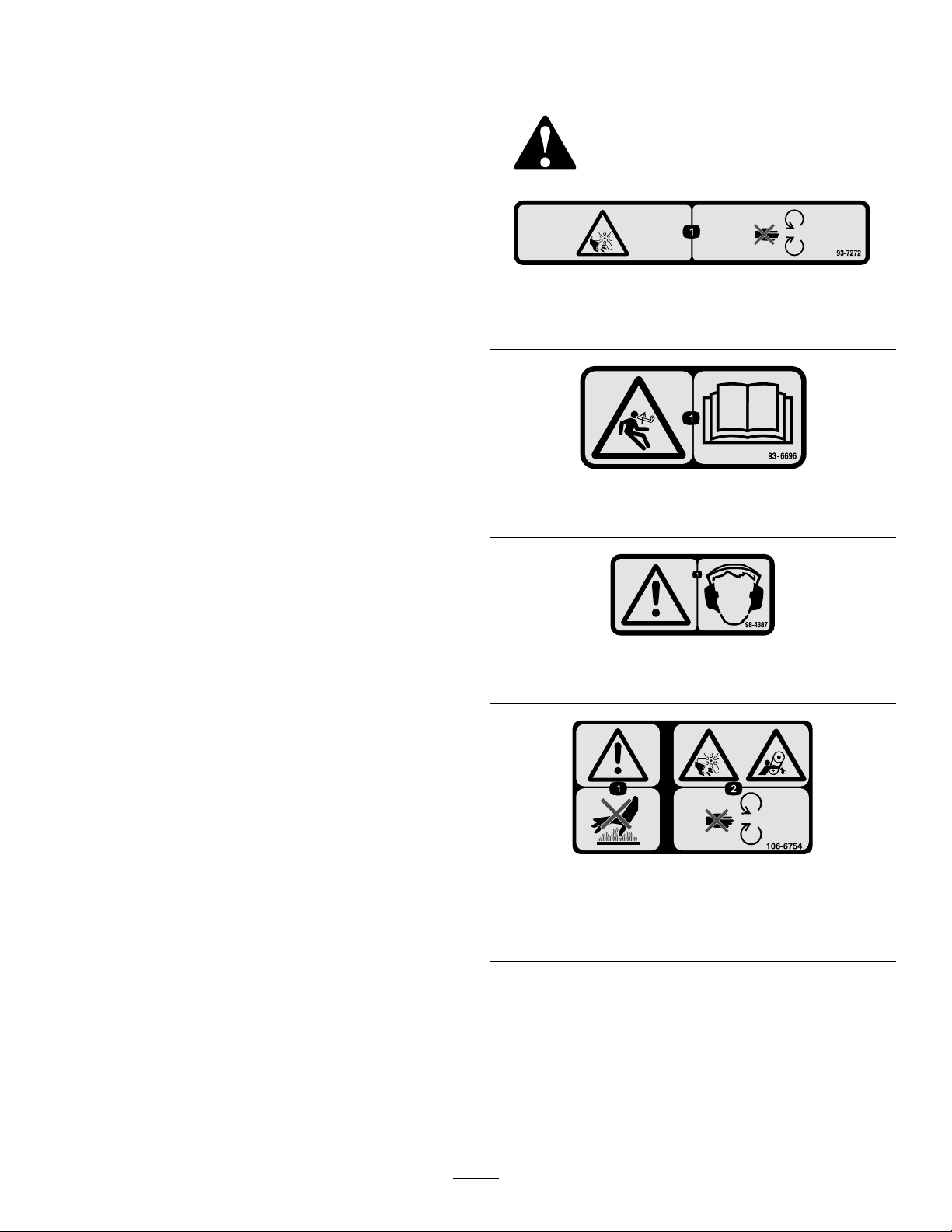
1.Cutting/dismembermenthazard;fan—stayawayfrom
movingparts.
93–6696
1.Storedenergyhazard—readtheOperator'sManual.
98-4387
1.Warning—wearhearingprotection.
Measuredvibrationlevel=0.23m/s
UncertaintyValue(K)=0.11m/s
Measuredvaluesweredeterminedaccordingtotheprocedures
outlinedinENISO5395:2013.
2
2
106-6754
1.Warning—donottouchthehotsurface.
2.Cutting/dismembermenthazard,fanandentanglement
hazard,belt—stayawayfrommovingparts.
7
110-0986
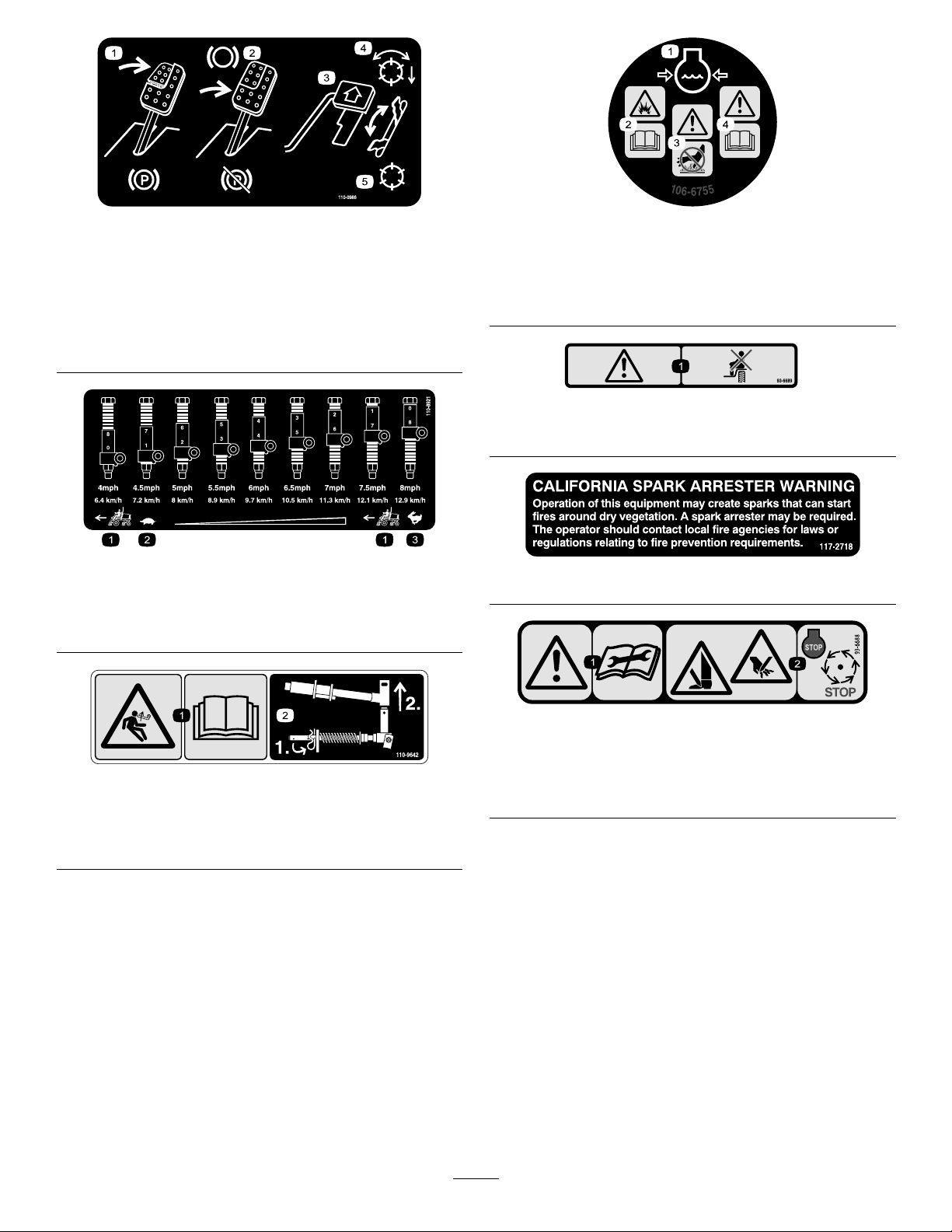
106-6755
1.Pressthebrakepedalandparkingbrakepedaltosetthe
parkingbrake.
2.Pressthebrakepedaltoapplythebrake.
3.Pressthetractionpedaltomovethemachineforward.
4.Reelenabledmode
5.Transportmode
110-8921
1.Tractionunitspeed
2.Slow
3.Fast
1.Enginecoolantunder
pressure.
2.Explosionhazard—read
theOperator'sManual.
1.Warning—donotcarrypassengers.
3.Warning—donottouchthe
hotsurface.
4.Warning—readthe
Operator'sManual.
93-6689
117–2718
110-9642
1.Storedenergyhazard—readtheOperator'sManual.
2.Movethecotterpintotheholeclosesttotherodbracket
andthenremovetheliftarmandpivotyoke.
1.Warning—readthe
instructionsbefore
servicingorperforming
maintenance.
93-6688
2.Cuttinghazardofhandor
foot—stoptheengineand
waitformovingpartsto
stop.
8

BatterySymbols
Someorallofthesesymbolsareonyourbattery
1.Explosionhazard
2.Nore,opename,or
smoking
3.Causticliquid/chemical
burnhazard
4.Weareyeprotection9.Flusheyesimmediately
5.ReadtheOperator's
Manual.
6.Keepbystandersasafe
7.Weareyeprotection;
8.Batteryacidcancause
10.Containslead;donot
distancefromthebattery.
explosivegasescan
causeblindnessandother
injuries.
blindnessorsevereburns.
withwaterandgetmedical
helpfast.
discard.
1.ReadtheOperator’s
Manual.
2.Engine—start4.Engine—stop
120–4158
3.Engine—preheat
125–8754
1.Headlights
2.Engage7.Lowerthecuttingunits
3.Powertake-off(PTO)
4.Disengage
5.Fast
6.Slow
8.Raisethecuttingunits
9.ReadtheOperator’s
Manual.
117–0169
1.ReadtheOperator'sManual.
2.Powerpoint—10A
3.Headlights—10A
4.Power—10A
5.Enginestart—15A
6.Optionalairrideseatsuspension—10A
7.EnginecomputermanagementC—10A
8.EnginecomputermanagementB—10A
9.EnginecomputermanagementA—10A
127-2470
9
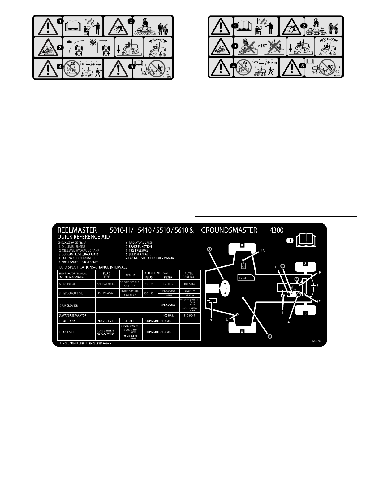
110-8869
1.Warning—readtheOperator'sManual,donotoperatethis
machineunlessyouaretrained.
2.Thrownobjecthazard—keepbystandersasafedistance
fromthemachine.
3.Tippinghazard—slowmachinebeforeturning,donotturn
athighspeeds;lowerthecuttingunitwhendrivingdown
slopes;usearolloverprotectionsystemandweartheseat
belt.AlwayswearaseatbeltwhenaROPSisinplace.
4.Warning—donotparkthemachineonslopes;engagethe
parkingbrake,lowerthecuttingdecks,stoptheengineand
removetheignitionkeybeforeleavingthemachine.
5.Warning—readtheOperator'sManual,donottowthe
machine.
110-8973
(AfxoverPartNumber1 10–8869forCE*)
*Thissafetydecalincludesaslopewarningrequiredonthemachineforcompliance
totheEuropeanLawnMowerSafetyStandardENISO5395:2013.Theconservative
maximumslopeanglesindicatedforoperationofthismachineareprescribedby
andrequiredbythisstandard.
1.Warning—readtheOperator'sManual,donotoperatethis
machineunlessyouaretrained.
2.Thrownobjecthazard—keepbystandersasafedistance
fromthemachine.
3.Tippinghazard—donotoperateonslopesgreaterthan15°;
lowerthecuttingdeckswhenoperatingonslopes;wear
thesafetybelt.
4.Warning—donotparkthemachineonslopes;engagethe
parkingbrake,lowerthecuttingdecks,stoptheengineand
removetheignitionkeybeforeleavingthemachine.
5.Warning—readtheOperator'sManualbeforetowingthe
machine.
1.ReadtheOperator'sManualformoremaintenanceinformation.
125-8753
10

Setup
LooseParts
Usethechartbelowtoverifythatallpartshavebeenshipped.
ProcedureDescription
1
2
3
4
5
6
7
MediaandAdditionalParts
Description
Operator'sManual
Nopartsrequired
Nopartsrequired
Cuttingunits
Finishingkit1
Nopartsrequired
Hood-latchassembly1
Washer1
Cuttingunitkickstand
Qty.
1
ReadtheOperator'sManualbeforeoperatingthemachine.
Qty.
–
–
5
–
1Installthecutting-unitkickstand.
Adjustthetirepressure.
Adjustthecontrol-armposition.
Installthecuttingunits.
Mountthenishingkits(nishingkits
aresoldseparately).
Adjusttheturf-compensationspring.
InstalltheCEhoodlatch.
Use
Use
EngineOperator'sManual
PartsCatalog
DeclarationofConformity
OperatorTrainingMaterial
Note:Determinetheleftandrightsidesofthemachine
fromthenormaloperatingposition.
1
AdjustingtheTirePressure
NoPartsRequired
Procedure
Thetiresareover-inatedforshipping.Therefore,release
someoftheairtoreducethepressure.Correctairpressurein
thefrontandreartiresis83to103kPa(12to15psi).
1
1
1
1
Engineinformation
Usetoreferencepartnumbers
Declarationofconformity
Reviewbeforeoperatingthemachine
Important:Maintainevenpressureinalltirestoensure
uniformcontactwiththeturf.
11
2
1
G027133
3
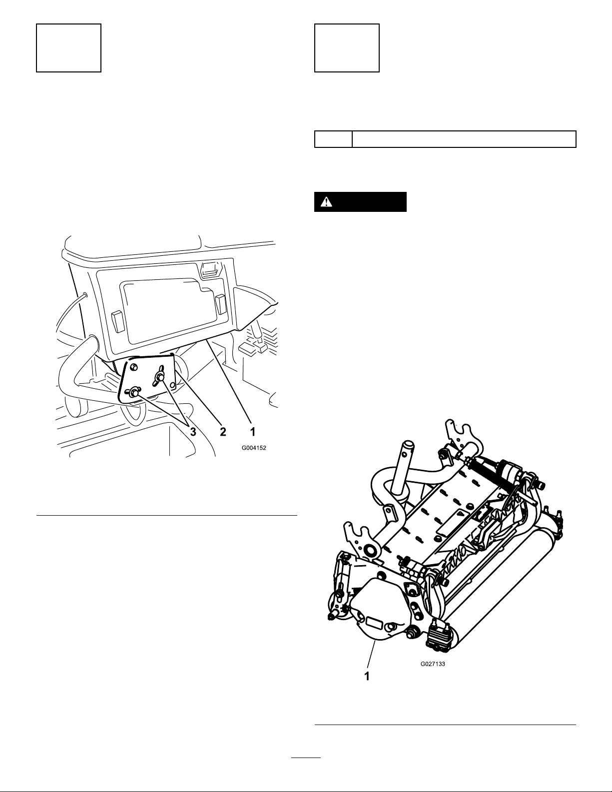
AdjustingtheControl-Arm Position
NoPartsRequired
Procedure
Thecontrol-armpositioncanbeadjustedforyourcomfort.
1.Loosenthe2boltssecuringthecontrolarmtothe
retainingbracket(Figure2).
InstallingtheCuttingUnits
Partsneededforthisprocedure:
5
Cuttingunits
Procedure
CAUTION
Ifyoudonotdisconnectthepowertothecutting
units,someonecouldaccidentallystartthecutting
unit,causingseriousinjurytohandsandfeet.
Alwaysseparatethepower-disconnectconnectors
beforeworkingonthecuttingunits(Figure26).
1.Disconnectthepower-disconnectconnector;referto
Cutting-Unit-PowerDisconnect(page20).
2.Removethecuttingunitsfromthecartons.Assemble
andadjustasdescribedinthecuttingunitOperator's
Manual.
Figure2
1.Controlarm3.Bolts(2)
2.Retainingbrackets
2.Rotatethecontrolarmtothedesiredpositionand
tightenthe2bolts.
3.Makesurethatthecounterweight(Figure3)isinstalled
totheproperendofthecuttingunitasdescribedinthe
counterweightkitInstallationInstructions.
Figure3
1.Counterweight
12
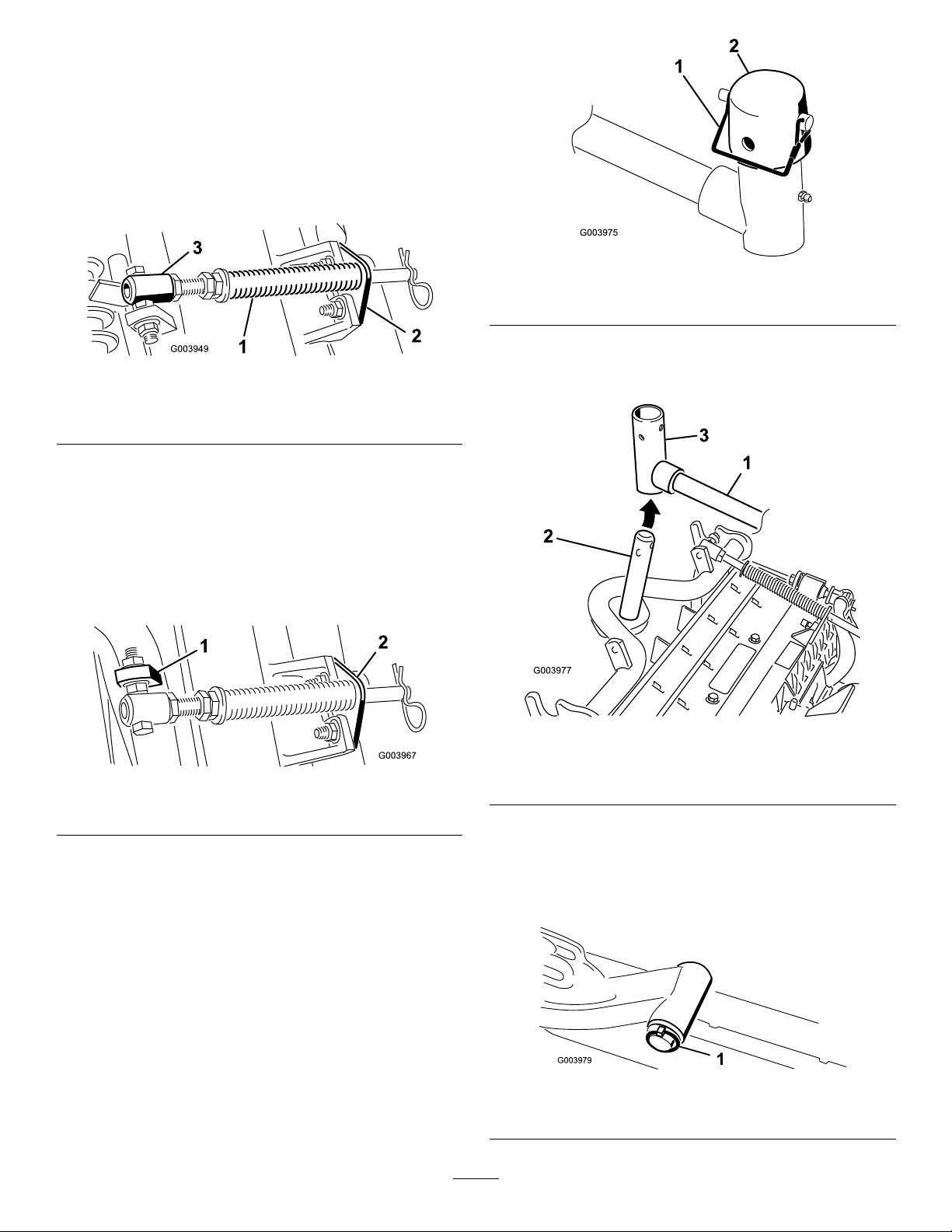
4.Mounttheturf-compensationspringtothesameside
ofthecuttingunitasthereel-drivemotor.Positionthe
turfcompensationasfollows:
Note:Allcuttingunitsareshippedwiththe
turf-compensationspringmountedtotherightside
ofthecuttingunit.
A.Removethe2carriageboltsandnutssecuringthe
rodbrackettothecutting-unittabs(Figure4).
Figure4
1.Turf-compensationspring3.Springtube
2.Rodbracket
B.Removetheangenutsecuringthespringtube
bolttothecarrier-frametab(Figure4)Remove
theassembly.
Figure6
1.Snapperpin2.Cap
7.Forthefrontcuttingunits,slideacuttingunitunder
theliftarmwhileinsertingthecarrier-frameshaftup
intothelift-arm-pivotyoke(Figure7).
C.Mountthespring-tubebolttotheoppositetabon
thecarrierframeandsecurewiththeangenut.
Note:Positiontotheboltheadtotheouterside
ofthetabasshowninFigure5.
Figure5
1.Oppositecarrier-frametab
2.Rodbracket
D.Mounttherodbrackettothecutting-unittabs
withthecarriageboltsandnuts(Figure5).
Note:Wheninstallingorremovingthecutting
units,makesurethatthehairpincotterisinstalled
inthespringrodholenexttotherodbracket.
Otherwise,installthehairpincotterintheholein
theendoftherod.
Figure7
1.Liftarm3.Lift-arm-pivotyoke
2.Carrier-frameshaft
8.Usethefollowingprocedureontherearcuttingunits
whentheheightofcutisabove19mm(3/4inch).
A.Removethelynchpinandwashersecuringthe
lift-arm-pivotshafttotheliftarmandslidethe
lift-arm-pivotshaftoutoftheliftarm(Figure8).
5.Lowerallliftarmscompletely.
6.Removethesnapperpinandthecapfromtheliftarm
pivotyoke(Figure6).
Figure8
1.Lynchpinandwasher
13
B.Insertthelift-armyokeontothecarrier-frame
12
g027140
shaft(Figure7).
C.Insertthelift-armshaftintotheliftarmand
secureitwiththewasherandlynchpin(Figure8).
9.Insertthecapoverthecarrier-frameshaftandlift-arm
yoke.
10.Securethecapandthecarrier-frameshafttothe
lift-armyokewiththesnapperpin(Figure6).
Note:Usetheslotifasteeringcuttingunitisdesired
orusetheholeifthecuttingunitistobelockedin
position.
11.Securethelift-armchaintothechainbracketwiththe
snapperpin(Figure9).
Note:Usethenumberofchainlinksdescribedinthe
cuttingunitOperator'sManual.
Figure9
1.Lift-armchain
2.Chainbracket
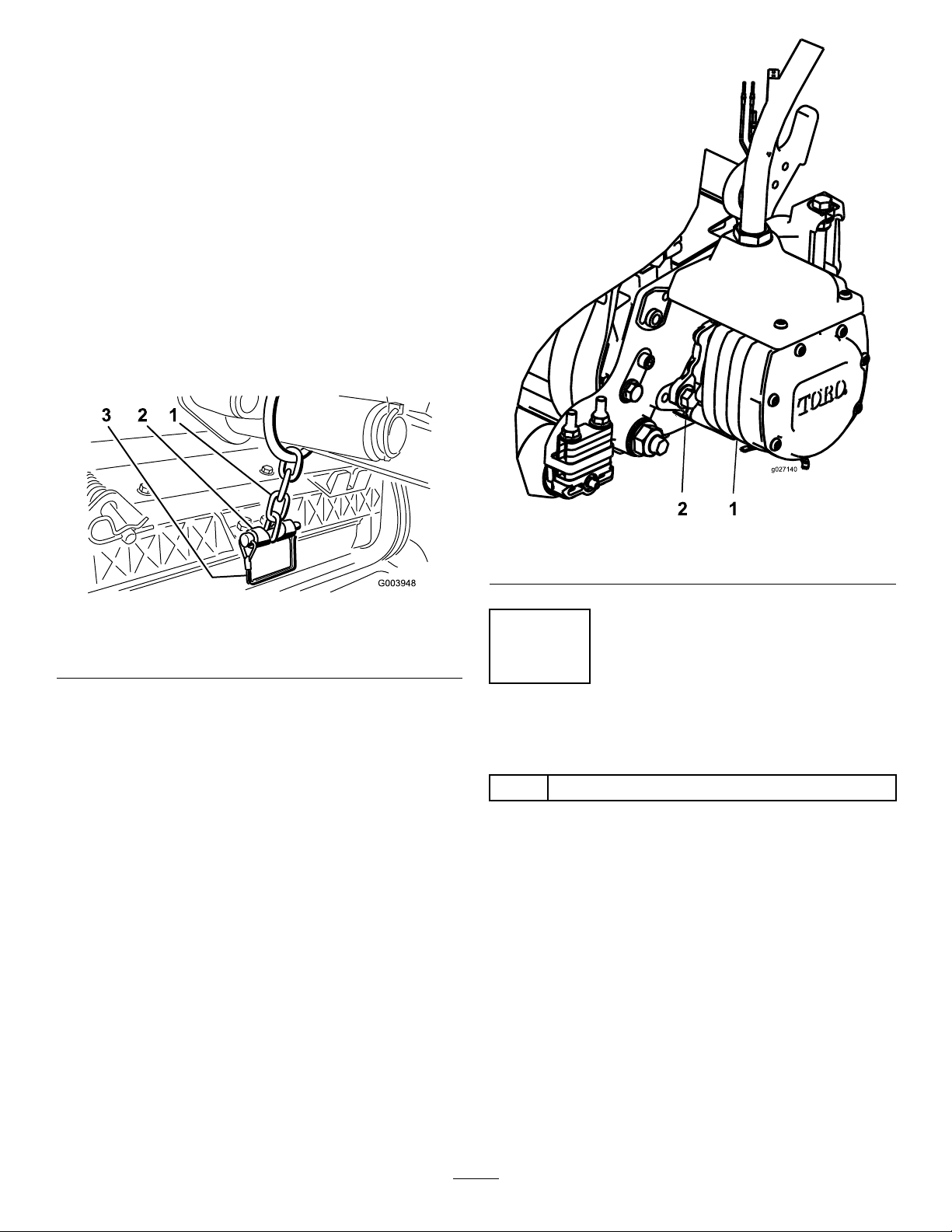
12.Coatthesplineshaftofthereelmotorwithclean
grease.
13.OilthereelmotorO-ringandinstallitontothemotor
ange.
14.Installthemotorbyrotatingitclockwisesothatthe
motorangesclearthebolts(Figure10).
Note:Rotatethemotorcounterclockwiseuntilthe
angesencircletheboltsandthentightenthebolts.
Important:Makesurethatthereel-motorhoseis
nottwisted,kinkedorintheriskofbeingpinched.
3.Pin
Figure10
1.Reel-drivemotor
2.Mountingbolt(2)
4
MountingtheFinishingKits
Partsneededforthisprocedure:
1Finishingkit
Procedure
Important:Toensurethatthehoseroutingis
appropriateandthehosesarenottwisted,mount
themotorstothecuttingunitsbeforemountingthe
nishingkits.
1.Onthefrontleftcorneroftheframe(#4cuttingunit
location),removetheextraangeheadnutonthebolt
securingthebulkheadbrackettothemachine(Figure
11).
2.Loosenthenutsonthenishingkithosetting,insert
thehoseintotheslotonthebulkheadbracketand
tightenthenuts.
Note:Whentighteningthenuts,useabackupwrench
topreventthehosefromtwistingorkinking.
14
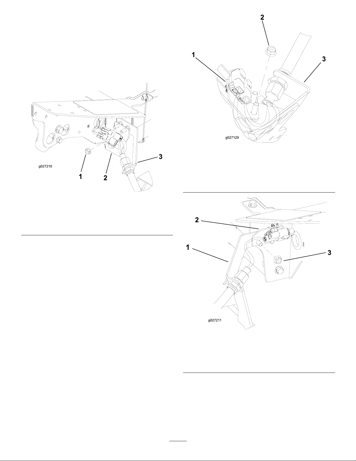
3.Inserttheconnectorplateontothebulkhead-mounting
2
3
g027210
1
2
3
g027129
g02721 1
3
2
boltswiththeconnectorspositionedasshownin
Figure11.
4.Securetheconnectorplateto1ofthemountingbolts
withtheangenutpreviouslyremoved.
5.Locatethewireharnessonthemachineandplug
thewireconnectorsintothewireconnectorsofthe
nishingkit.
Figure12
#1CuttingUnitLocation,CenterFront
(Asviewedfromunderthemachine)
1.Extraange-headnut
2.Connectorplate
6.Repeattheprocedureontheremaining4bulkhead
Figure11
#4CuttingUnitLocation,LeftFront
3.Bulkheadbracket
locationsasshowninFigure12throughFigure15.
Important:Theconnectorplatesarepositioned
differentlyattheremaininglocationssothehose
canberoutedthroughthebulkheadbracketandto
thecuttingunitwithoutgettingtwistedorkinked.
1.Connectorplate
2.Extraange-headnut
#5CuttingUnitLocation,RightFront
1.Bulkheadbracket
2.Connectorplate
3.Bulkheadbracket
Figure13
3.Extraange-headnut
15

Figure14
g027209
2
1
3
#3CuttingUnitLocation,RightRear
1.Extraange-headnut3.Connectorplate
2.Bulkheadbracket
5
Adjustingthe Turf-CompensationSpring
NoPartsRequired
Procedure
Theturf-compensationspring(Figure16)transferstheweight
fromthefronttotherearroller.Thishelpstoreduceawave
patternintheturf,alsoknownasmarcellingorbobbing.
Important:Makespringadjustmentswiththecutting
unitmountedtothetractionunit,pointingstraight
aheadandloweredtotheground.
1.Makesurethatthehairpincotterisinstalledintherear
holeinthespringrod(Figure16).
#2CuttingUnitLocation,LeftRear
1.Bulkheadbracket
2.Extraange-headnut
Figure15
3.Connectorplate
Figure16
1.Turf-compensationspring3.Springrod
2.Hairpincotter4.Hexnuts
2.Tightenthehexnutsonthefrontendofthespringrod
untilthecompressedlengthofthespringis12.7cm(5
inches)for5-inchcuttingunitsor15.9cm(6.25inches)
for7-inchcuttingunits(Figure16).
Note:Whenoperatingonroughterraindecrease
thespringlengthby12.7mm(1/2inch).Ground
followingwillbeslightlydecreased.
16

g027072
4.Outsidethehood,insertthehookendofthelatch
throughtheholeinthehood.Makesurethatthe
6
rubbersealingwasherremainsontheoutsideofthe
hood.
InstallingtheCEHoodLatch
Partsneededforthisprocedure:
1Hood-latchassembly
1Washer
Procedure
1.Unlatchandraisethehood.
2.Removetherubbergrommetfromtheholeintheleft
sideofthehood(Figure17).
5.Insidethehood,insertthemetalwasherontothelatch
andsecurewiththenut.Makesurethatthelatch
engagestheframecatchwhenitislocked.Usethe
enclosedhood-latchkeytooperatethehoodlatch.
7
UsingtheCutting-Unit Kickstand
Partsneededforthisprocedure:
1
Cuttingunitkickstand
Procedure
Wheneverthecuttingunithastobetippedtoexposethe
bedknife/reel,propuptherearofthecuttingunitwiththe
kickstandtomakesurethatthenutsonthebackendofthe
bedbar-adjustingscrewsarenotrestingontheworksurface
(Figure19).
Figure17
1.Rubbergrommet
3.Removethenutfromthehood-latchassembly(Figure
18).
Figure18
1.Hoodlatch3.Rubberwasher
2.Nut4.Metalwasher
Figure19
1.Cutting-unitkickstand
Securethekickstandtothechainbracketwiththesnapper
pin(Figure20).
17
 Loading...