

Page 1

FormNo.3382-316RevB
Reelmaster
ModelNo.03672—SerialNo.314000001andUp
ModelNo.03672A—SerialNo.314000001andUp
ModelNo.03687—SerialNo.314000001andUp
ModelNo.03687A—SerialNo.314000001andUp
®
5410-DTractionUnit
Registeratwww.T oro.com.
OriginalInstructions(EN)
*3382-316*B
Page 2
WARNING
CALIFORNIA
Proposition65Warning
Thisproductcontainsachemical
orchemicalsknowntotheStateof
Californiatocausecancer,birthdefects,
orreproductiveharm.
Dieselengineexhaustandsomeofits
constituentsareknowntotheStateof
Californiatocausecancer,birthdefects,
andotherreproductiveharm.
Becauseinsomeareastherearelocal,state,or
federalregulationsrequiringthatasparkarresterbe
usedontheengineofthismachine,asparkarrester
isincorporatedwiththemuferassembly.
GenuineT orosparkarrestersareapprovedbythe
USDAForestryService.
Important:Thisengineisequippedwithaspark
arrestermufer.ItisaviolationofCalifornia
PublicResourceCodeSection4442touse
oroperatetheengineonanyforest-covered,
brush-covered,orgrass-coveredlandwithout
asparkarrestermufermaintainedinworking
order,ortheengineconstricted,equipped,and
maintainedforthepreventionofre.Otherstates
orfederalareasmayhavesimilarlaws.
andserialnumbersofyourproductready.Themodel
andserialnumbersareonaplatemountedonthe
leftsideoftheframeunderthefootrest.Writethe
numbersinthespaceprovided.
ModelNo.
SerialNo.
Thismanualidentiespotentialhazardsandhas
safetymessagesidentiedbythesafetyalertsymbol
(Figure1),whichsignalsahazardthatmaycause
seriousinjuryordeathifyoudonotfollowthe
recommendedprecautions.
g000502
Figure1
1.Safetyalertsymbol
Thismanualuses2otherwordstohighlight
information.Importantcallsattentiontospecial
mechanicalinformationandNoteemphasizesgeneral
informationworthyofspecialattention.
Introduction
Thismachineisaride-on,reel-bladelawnmower
intendedtobeusedbyprofessional,hiredoperators
incommercialapplications.Itisprimarilydesigned
forcuttinggrassonwell-maintainedlawnsingolf
courses,parks,sportselds,andoncommercial
grounds.Itisnotdesignedforcuttingbrush,mowing
grassandothergrowthalongsidehighways,orfor
agriculturaluses.
Readthisinformationcarefullytolearnhowtooperate
andmaintainyourproductproperlyandtoavoid
injuryandproductdamage.Youareresponsiblefor
operatingtheproductproperlyandsafely .
YoumaycontactT orodirectlyatwww.T oro.comfor
productandaccessoryinformation,helpndinga
dealer,ortoregisteryourproduct.
Wheneveryouneedservice,genuineToroparts,or
additionalinformation,contactanAuthorizedService
DealerorToroCustomerServiceandhavethemodel
©2017—TheToro®Company
8111LyndaleAvenueSouth
Bloomington,MN55420
Contactusatwww.Toro.com.
2
PrintedintheUSA.
AllRightsReserved
Page 3

Contents
Safety.......................................................................4
SafeOperatingPractices....................................4
ToroRidingMowerSafety...................................6
EngineEmissionCertication.............................7
SafetyandInstructionalDecals..........................8
Setup......................................................................12
1AdjustingtheTirePressure............................13
2AdjustingtheStepHeight...............................13
3AdjustingtheControlArmPosition.................13
4InstallingtheCuttingUnits..............................13
5AdjustingtheTurfCompensation
Spring...........................................................17
6UsingtheCuttingUnitKickstand....................17
ProductOverview...................................................18
Controls...........................................................18
Specications..................................................25
Attachments/Accessories.................................25
Operation................................................................25
CheckingtheEngine-OilLevel..........................25
FillingtheFuelTank..........................................26
CheckingtheCoolingSystem...........................27
CheckingtheHydraulicFluid............................28
CheckingtheReeltoBedknifeContact.............28
ChecktheT orqueoftheWheelNuts.................29
StartingandStoppingtheEngine......................29
SettingtheReelSpeed.....................................29
CuttingGrasswiththeMachine........................29
DieselParticulateFilterRegeneration...............30
AdjustingtheLiftArmCounterbalance..............38
AdjustingtheLiftArmTurnAround
Position.........................................................38
PushingorT owingtheMachine........................38
JackingPoints..................................................39
TieDowns.........................................................39
UnderstandingtheDiagnosticLight..................40
CheckingtheInterlockSwitches.......................40
HydraulicValveSolenoidFunctions..................41
OperatingTips.................................................41
Maintenance...........................................................42
RecommendedMaintenanceSchedule(s)...........42
DailyMaintenanceChecklist.............................43
ServiceIntervalChart.......................................44
Lubrication..........................................................44
GreasingtheBearingsandBushings................44
EngineMaintenance...........................................46
ServicingtheAirCleaner..................................46
ServicingtheEngineOil....................................46
ServicingtheDiesel-OxidationCatalyst
(DOC)andtheSootFilter..............................48
FuelSystemMaintenance...................................48
ServicingtheWaterSeparator.........................48
ServicingtheEngineFuelFilter........................49
CheckingtheFuelLinesand
Connections..................................................49
FuelPick-upTubeScreen.................................49
ElectricalSystemMaintenance...........................50
ServicingtheBattery.........................................50
Fuses................................................................50
DriveSystemMaintenance..................................51
AdjustingtheTractionDriveforNeutral.............51
AdjustingtheRearWheelToe-in.......................51
CoolingSystemMaintenance..............................52
RemovingDebrisfromtheCooling
System..........................................................52
BrakeMaintenance.............................................53
AdjustingtheServiceBrakes............................53
AdjustingtheParkingBrake.............................53
BeltMaintenance................................................54
ServicingtheAlternatorBelt.............................54
HydraulicSystemMaintenance...........................54
ChangingtheHydraulicFluid............................54
ReplacingtheHydraulicFilters.........................55
CheckingtheHydraulicLinesand
Hoses............................................................55
HydraulicSystemT estPorts.............................56
CuttingUnitSystemMaintenance........................57
BacklappingtheCuttingUnits...........................57
Storage...................................................................58
PreparingtheTractionUnit...............................58
PreparingtheEngine........................................58
3
Page 4

Safety
Improperuseormaintenancebytheoperator
orownercanresultininjury .T oreducethe
potentialforinjury ,complywiththesesafety
instructionsandalwayspayattentiontothesafety
alertsymbol,whichmeansCaution,Warning,or
Danger—personalsafetyinstruction.Failureto
complywiththeinstructionmayresultinpersonal
injuryordeath.
SafeOperatingPractices
ThefollowinginstructionsarefromtheCENstandard
EN836:1997,ISOstandard5395:1990,andANSI
B71.4-2012.
Training
•Readtheoperator'smanualandothertraining
materialcarefully.Befamiliarwiththecontrols,
safetysigns,andtheproperuseoftheequipment.
•Neverallowchildrenorpeopleunfamiliarwith
theseinstructionstouseorservicethemower.
Localregulationsmayrestricttheageofthe
operator.
•Nevermowwhilepeople,especiallychildren,or
petsarenearby.
•Keepinmindthattheoperatororuseris
responsibleforaccidentsorhazardsoccurringto
otherpeopleortheirproperty.
•Donotcarrypassengers.
•Alldriversandmechanicsshouldseekandobtain
professionalandpracticalinstruction.Theowneris
responsiblefortrainingtheusers.Suchinstruction
shouldemphasize:
–theneedforcareandconcentrationwhen
workingwithride-onmachines;
–controlofaride-onmachineslidingonaslope
willnotberegainedbytheapplicationofthe
brake.Themainreasonsforlossofcontrolare:
◊insufcientwheelgrip;
◊beingdriventoofast;
◊inadequatebraking;
◊thetypeofmachineisunsuitableforits
task;
◊lackofawarenessoftheeffectofground
conditions,especiallyslopes;
◊incorrecthitchingandloaddistribution.
•Theowner/usercanpreventandisresponsible
foraccidentsorinjuriesoccurringtohimselfor
herself,otherpeople,orproperty.
Preparation
•Whilemowing,alwayswearsubstantialfootwear,
longtrousers,hardhat,safetyglasses,andear
protection.Longhair,looseclothing,orjewelry
maygettangledinmovingparts.Donotoperate
theequipmentwhenbarefootorwearingopen
sandals.
•Thoroughlyinspecttheareawheretheequipment
istobeusedandremoveallobjectswhichmaybe
thrownbythemachine.
•Replacefaultysilencers/mufers.
•Evaluatetheterraintodeterminewhataccessories
andattachmentsareneededtoproperlyand
safelyperformthejob.Onlyuseaccessoriesand
attachmentsapprovedbythemanufacturer.
•Checkthattheoperator'spresencecontrols,
safetyswitchesandshieldsareattachedand
functioningproperly.Donotoperateunlessthey
arefunctioningproperly.
SafeHandlingofFuels
•Toavoidpersonalinjuryorpropertydamage,use
extremecareinhandlinggasoline.Gasolineis
extremelyammableandthevaporsareexplosive.
•Extinguishallcigarettes,cigars,pipes,andother
sourcesofignition.
•Useonlyanapprovedfuelcontainer.
•Neverremovefuelcaporaddfuelwiththeengine
running.
•Allowenginetocoolbeforerefueling.
•Neverrefuelthemachineindoors.
•Neverstorethemachineorfuelcontainerwhere
thereisanopename,spark,orpilotlightsuchas
onawaterheateroronotherappliances.
•Neverllcontainersinsideavehicleoronatruck
ortrailerbedwithaplasticliner.Alwaysplace
containersonthegroundawayfromyourvehicle
beforelling.
•Removeequipmentfromthetruckortrailerand
refuelitontheground.Ifthisisnotpossible,then
refuelsuchequipmentwithaportablecontainer,
ratherthanfromafueldispensernozzle.
•Keepthenozzleincontactwiththerimofthefuel
tankorcontaineropeningatalltimesuntilfueling
iscomplete.Donotuseanozzlelockopendevice.
•Iffuelisspilledonclothing,changeclothing
immediately.
•Neveroverllfueltank.Replacefuelcapand
tightensecurely.
4
Page 5

Operation
•Donotoperatetheengineinaconnedspace
wheredangerouscarbonmonoxidefumescan
collect.
•Mowonlyindaylightoringoodarticiallight.
•Beforeattemptingtostarttheengine,disengage
allbladeattachmentclutches,shiftintoneutral,
andengagetheparkingbrake.
•Rememberthereisnosuchthingasasafeslope.
Travelongrassslopesrequiresparticularcare.T o
guardagainstoverturning:
–donotstoporstartsuddenlywhengoingup
ordownhill;
–machinespeedsshouldbekeptlowonslopes
andduringtightturns;
–stayalertforhumpsandhollowsandother
hiddenhazards;
–Donotturnsharply.Usecarewhenreversing.
–Usecounterweight(s)orwheelweightswhen
suggestedintheoperator'smanual.
•Stayalertforholesintheterrainandotherhidden
hazards.
•Watchoutfortrafcwhencrossingornear
roadways.
•Stopthebladesrotatingbeforecrossingsurfaces
otherthangrass.
•Whenusinganyattachments,neverdirect
dischargeofmaterialtowardbystandersnorallow
anyonenearthemachinewhileinoperation.
•Neveroperatethemachinewithdamagedguards,
shields,orwithoutsafetyprotectivedevicesin
place.Besureallinterlocksareattached,adjusted
properly,andfunctioningproperly .
•Donotchangetheenginegovernorsettingsor
over-speedtheengine.Operatingtheengine
atexcessivespeedmayincreasethehazardof
personalinjury.
•Beforeleavingtheoperator'sposition:
–stoponlevelground;
–disengagethepowertake-offandlowerthe
attachments;
–changeintoneutralandsettheparkingbrake;
–stoptheengineandremovethekey.
•Disengagedrivetoattachmentswhentransporting
ornotinuse.
•Stoptheengineanddisengagedriveto
attachment:
–beforerefuelling;
–beforeremovingthegrasscatcher/catchers;
–beforemakingheightadjustmentunless
adjustmentcanbemadefromtheoperator's
position.
–beforeclearingblockages;
–beforechecking,cleaningorworkingonthe
mower;
–afterstrikingaforeignobjectorifanabnormal
vibrationoccurs.Inspectthemowerfor
damageandmakerepairsbeforerestarting
andoperatingtheequipment.
•Reducetheenginespeedsettingduringengine
run-outand,iftheengineisprovidedwithashut-off
valve,turnthefueloffattheconclusionofmowing.
•Keephandsandfeetawayfromthecuttingunits.
•Lookbehindanddownbeforebackinguptobe
sureofaclearpath.
•Slowdownandusecautionwhenmaking
turnsandcrossingroadsandsidewalks.Stop
cylinders/reelsifnotmowing.
•Donotoperatethemowerundertheinuenceof
alcoholordrugs.
•Lightningcancausesevereinjuryordeath.If
lightningisseenorthunderisheardinthearea,do
notoperatethemachine;seekshelter.
•Usecarewhenloadingorunloadingthemachine
intoatrailerortruck.
•Usecarewhenapproachingblindcorners,shrubs,
trees,orotherobjectsthatmayobscurevision.
MaintenanceandStorage
•Keepallnuts,boltsandscrewstighttobesurethe
equipmentisinsafeworkingcondition.
•Neverstoretheequipmentwithfuelinthetank
insideabuildingwherefumesmayreachanopen
ameorspark.
•Allowtheenginetocoolbeforestoringinany
enclosure.
•Toreducetherehazard,keeptheengine,
silencer/mufer,batterycompartmentandfuel
storageareafreeofgrass,leaves,orexcessive
grease.
•Checkthegrasscatcherfrequentlyforwearor
deterioration.
•Keepallpartsingoodworkingconditionandall
hardwareandhydraulicttingstightened.Replace
allwornordamagedpartsanddecals.
•Ifthefueltankhastobedrained,dothisoutdoors.
•Becarefulduringadjustmentofthemachineto
prevententrapmentofthengersbetweenmoving
bladesandxedpartsofthemachine.
•Onmulti-cylinder/multi-reelmachines,takecare
asrotatingonecylinder/reelcancauseother
cylinders/reelstorotate.
•Disengagedrives,lowerthecuttingunits,set
parkingbrake,stopengineandremovekeyfrom
5
Page 6

ignition.Waitforallmovementtostopbefore
adjusting,cleaningorrepairing.
•Cleangrassanddebrisfromcuttingunits,drives,
silencers/mufers,andenginetohelpprevent
res.Cleanupoilorfuelspillage.
•Usejackstandstosupportcomponentswhen
required.
•Carefullyreleasepressurefromcomponentswith
storedenergy.
•Disconnectbatterybeforemakinganyrepairs.
Disconnectthenegativeterminalrstandthe
positivelast.Reconnectpositiverstandnegative
last.
•Usecarewhencheckingthecylinders/reels.Wear
glovesandusecautionwhenservicingthem.
•Keephandsandfeetawayfrommovingparts.If
possible,donotmakeadjustmentswiththeengine
running.
•Chargebatteriesinanopenwellventilatedarea,
awayfromsparkandames.Unplugcharger
beforeconnectingordisconnectingfrombattery.
Wearprotectiveclothinganduseinsulatedtools.
Hauling
•Usecarewhenloadingorunloadingthemachine
intoatrailerortruck.
•Usefullwidthrampsforloadingmachineinto
trailerortruck.
•Tiethemachinedownsecurelyusingstraps,
chains,cable,orropes.Bothfrontandrearstraps
shouldbedirecteddownandoutwardfromthe
machine
ToroRidingMowerSafety
Thefollowinglistcontainssafetyinformationspecic
toT oroproductsorothersafetyinformationthatyou
mustknowthatisnotincludedintheCEN,ISO,or
ANSIstandard.
Thisproductiscapableofamputatinghandsand
feetandthrowingobjects.Alwaysfollowallsafety
instructionstoavoidseriousinjuryordeath.
Useofthisproductforpurposesotherthanitsintended
usecouldprovedangeroustouserandbystanders.
WARNING
Engineexhaustcontainscarbonmonoxide,
whichisanodorless,deadlypoisonthatcan
killyou.
Donotrunengineindoorsorinanenclosed
area.
•Knowhowtostoptheenginequickly.
•Donotoperatethemachinewhilewearingtennis
shoesorsneakers.
•Wearingsafetyshoesandlongpantsisadvisable
andrequiredbysomelocalordinancesand
insuranceregulations.
•Handlefuelcarefully.Wipeupanyspills.
•Checkthesafetyinterlockswitchesdailyforproper
operation.Ifaswitchshouldfail,replacethe
switchbeforeoperatingthemachine.
•Beforestartingtheengine,sitontheseat.
•Usingthemachinedemandsattention.T oprevent
lossofcontrol:
–Donotdriveclosetosandtraps,ditches,
creeks,orotherhazards.
–Reducespeedwhenmakingsharpturns.
Avoidsuddenstopsandstarts.
–Whennearorcrossingroads,alwaysyieldthe
right-of-way.
–Applytheservicebrakeswhengoingdownhill
tokeepforwardspeedslowandtomaintain
controlofthemachine.
•Raisethecuttingunitswhendrivingfromonework
areatoanother.
•Donottouchtheengine,silencer/mufer,or
exhaustpipewhiletheengineisrunningorsoon
afterithasstoppedbecausetheseareascouldbe
hotenoughtocauseburns.
•Iftheenginestallsorlosesheadwayandcannot
makeittothetopofaslope,donotturnthe
machinearound.Alwaysbackslowly ,straight
downtheslope.
•Whenapersonorpetappearsunexpectedlyin
ornearthemowingarea,stopmowing.Careless
operation,combinedwithterrainangles,ricochets,
orimproperlypositionedguardscanleadtothrown
objectinjuries.Donotresumemowinguntilthe
areaiscleared.
MaintenanceandStorage
•Makesureallhydrauliclineconnectorsaretight
andallhydraulichosesandlinesareingood
conditionbeforeapplyingpressuretothesystem.
•Keepyourbodyandhandsawayfrompinhole
leaksornozzlesthatejecthydraulicuidunder
highpressure.Usepaperorcardboard,not
yourhands,tosearchforleaks.Hydraulicuid
escapingunderpressurecanhavesufcient
forcetopenetratetheskinandcauseserious
injury.Seekimmediatemedicalattentionifuidis
injectedintoskin.
•Beforedisconnectingorperforminganyworkon
thehydraulicsystem,allpressureinthesystem
mustberelievedbystoppingtheengineand
6
Page 7

loweringthecuttingunitsandattachmentstothe
ground.
•Checkallfuellinesfortightnessandwearona
regularbasis.Tightenorrepairthemasneeded.
•Iftheenginemustberunningtoperforma
maintenanceadjustment,keephands,feet,
clothing,andanypartsofthebodyawayfromthe
cuttingunits,attachments,andanymovingparts.
Keepeveryoneaway.
•Toensuresafetyandaccuracy,haveanAuthorized
ToroDistributorcheckthemaximumenginespeed
withatachometer.
•Ifmajorrepairsareeverneededorifassistanceis
desired,contactanAuthorizedToroDistributor.
•UseonlyToro-approvedattachmentsand
replacementparts.Thewarrantymaybevoidedif
usedwithunapprovedattachments.
EngineEmission
Certication
TheengineinthismachineisEPATier4Finaland
stage3bcompliant.
7
Page 8
SafetyandInstructionalDecals
Safetydecalsandinstructionsareeasilyvisibletotheoperatorandarelocatednearanyarea
ofpotentialdanger.Replaceanydecalthatisdamagedorlost.
93-7272
1.Cutting/dismemberment—hazard,fan-stayawayfrom
movingparts.
decal93-7272
decal106-6755
106-6755
93–6696
1.Storedenergyhazard—readtheOperator'sManual.
106-6754
1.Warning—donottouchthehotsurface.
2.Cutting/dismembermenthazard,fanandentanglement
hazard,belt—stayawayfrommovingparts.
1.Enginecoolantunder
pressure.
2.Explosionhazard—read
decal93-6696
theOperator'sManual.
3.Warning—donottouchthe
hotsurface.
4.Warning—readthe
Operator'sManual.
decal110-9642
110-9642
1.Storedenergyhazard—readtheOperator'sManual.
2.Movethecotterpintotheholeclosesttotherodbracket
decal106-6754
andthenremovetheliftarmandpivotyoke.
decal98-4387
98-4387
110-0986
1.Pressthebrakepedalandparkingbrakepedaltosetthe
parkingbrake.
2.Pressthebrakepedaltoapplythebrake.
3.Pressthetractionpedaltomovethemachineforward.
4.Reelenabledmode
5.Transportmode
1.Warning—wearhearingprotection.
decal110-0986
8
Page 9
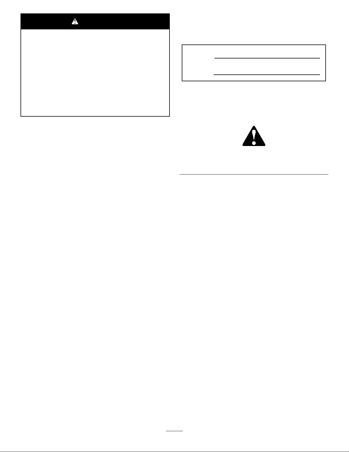
117–0169
1.ReadtheOperator'sManual.
2.Powerpoint—10amp
3.Headlights—10amp
4.Power—10amp
5.Enginestart—15amp
6.Optionalairrideseatsuspension—10amp
7.EnginecomputermanagementC—10amp
8.EnginecomputermanagementB—10amp
9.EnginecomputermanagementA—10amp
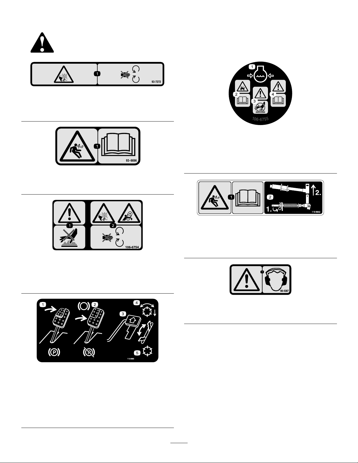
r:\decal110-8869
110-8869
1.Warning—readtheOperator'sManual,donotoperatethis
machineunlessyouaretrained.
2.Thrownobjecthazard—keepbystandersasafedistance
fromthemachine.
3.Tippinghazard—slowmachinebeforeturning,donotturn
athighspeeds;lowerthecuttingunitwhendrivingdown
slopes;usearolloverprotectionsystemandweartheseat
r:\decal117-0169
belt.AlwayswearaseatbeltwhenaROPSisinplace.
4.Warning—donotparkthemachineonslopes;engagethe
parkingbrake,lowerthecuttingdecks,stoptheengineand
removetheignitionkeybeforeleavingthemachine.
5.Warning—readtheOperator'sManual,donottowthe
machine.
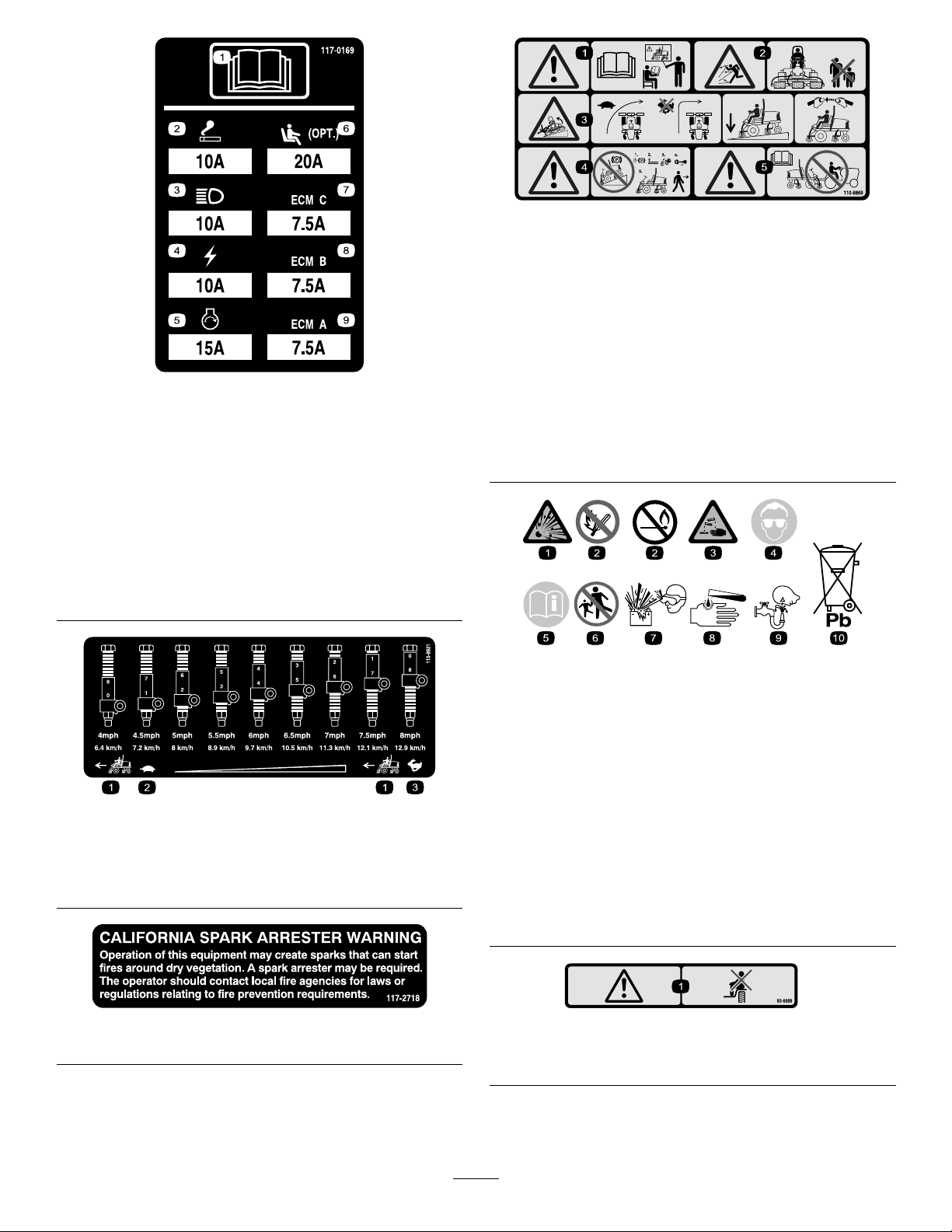
decalbatterysymbols
BatterySymbols
Someorallofthesesymbolsareonyourbattery
1.Tractionunitspeed
2.Slow
3.Fast
1.Explosionhazard
6.Keepbystandersasafe
distancefromthebattery.
2.Nore,opename,or
smoking.
7.Weareyeprotection;
explosivegasescan
causeblindnessandother
decal110-8921
110-8921
3.Causticliquid/chemical
burnhazard
injuries
8.Batteryacidcancause
blindnessorsevereburns.
4.Weareyeprotection9.Flusheyesimmediately
withwaterandgetmedical
helpfast.
5.ReadtheOperator's
Manual.
decal117-2718
117–2718
10.Containslead;donot
discard.
decal93-6689
93–6689
1.Danger—donotsitontheplasticshroud.
9
Page 10
110-8924
1.Warning—readtheOperator'sManualandreceivetraining.
2.Thrownobjecthazard—keepbystandersasafedistance
fromthemachine.
3.Warning—donotparkthemachineonslopes;engagethe
parkingbrake,lowerthecuttingunits,stoptheengineand
removetheignitionkeybeforeleavingthemachine.
4.Tippinghazard—slowmachinebeforeturning,donotturn
athighspeeds;lowerthecuttingunitwhendrivingdown
slopes.
5.Warning—readtheOperator'sManual,donottowthe
machine.
decal110-8924
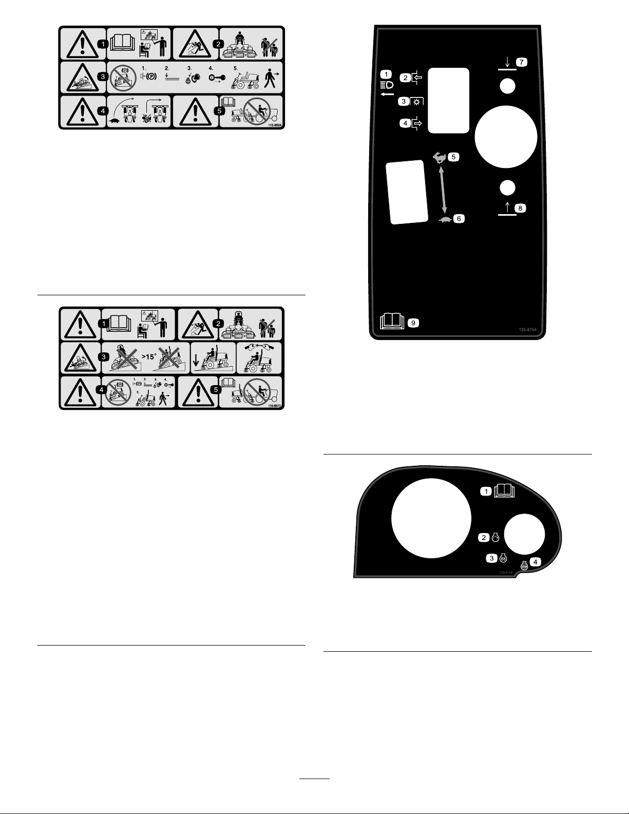
decal125-8754
125–8754
r:\decal110-8973
110-8973
(Afxoverpartno.1 10–8924forCE*)
*Thissafetydecalincludesaslopewarningrequiredonthemachinefor
compliancetotheEuropeanLawnMowerSafetyStandardEN836:1997.The
conservativemaximumslopeanglesindicatedforoperationofthismachineare
prescribedbyandrequiredbythisstandard.
1.Warning—readtheOperator'sManual,donotoperatethis
machineunlessyouaretrained.
2.Thrownobjecthazard—keepbystandersasafedistance
fromthemachine.
3.Tippinghazard—donotoperateonslopesgreaterthan15°;
lowerthecuttingdeckswhenoperatingonslopes;wear
thesafetybelt.
4.Warning—donotparkthemachineonslopes;engagethe
parkingbrake,lowerthecuttingdecks,stoptheengineand
removetheignitionkeybeforeleavingthemachine
5.Warning—readtheOperator'sManualbeforetowingthe
machine.
1.Headlights
6.Slow
2.Engage7.Lowerthecuttingunits
3.Powertake-off(PTO)
4.Disengage
8.Raisethecuttingunits
9.ReadtheOperator’s
Manual.
5.Fast
120–4158
1.ReadtheOperator’s
Manual.
2.Engine—start4.Engine—stop
3.Engine—preheat
decal120-4158
10
Page 11
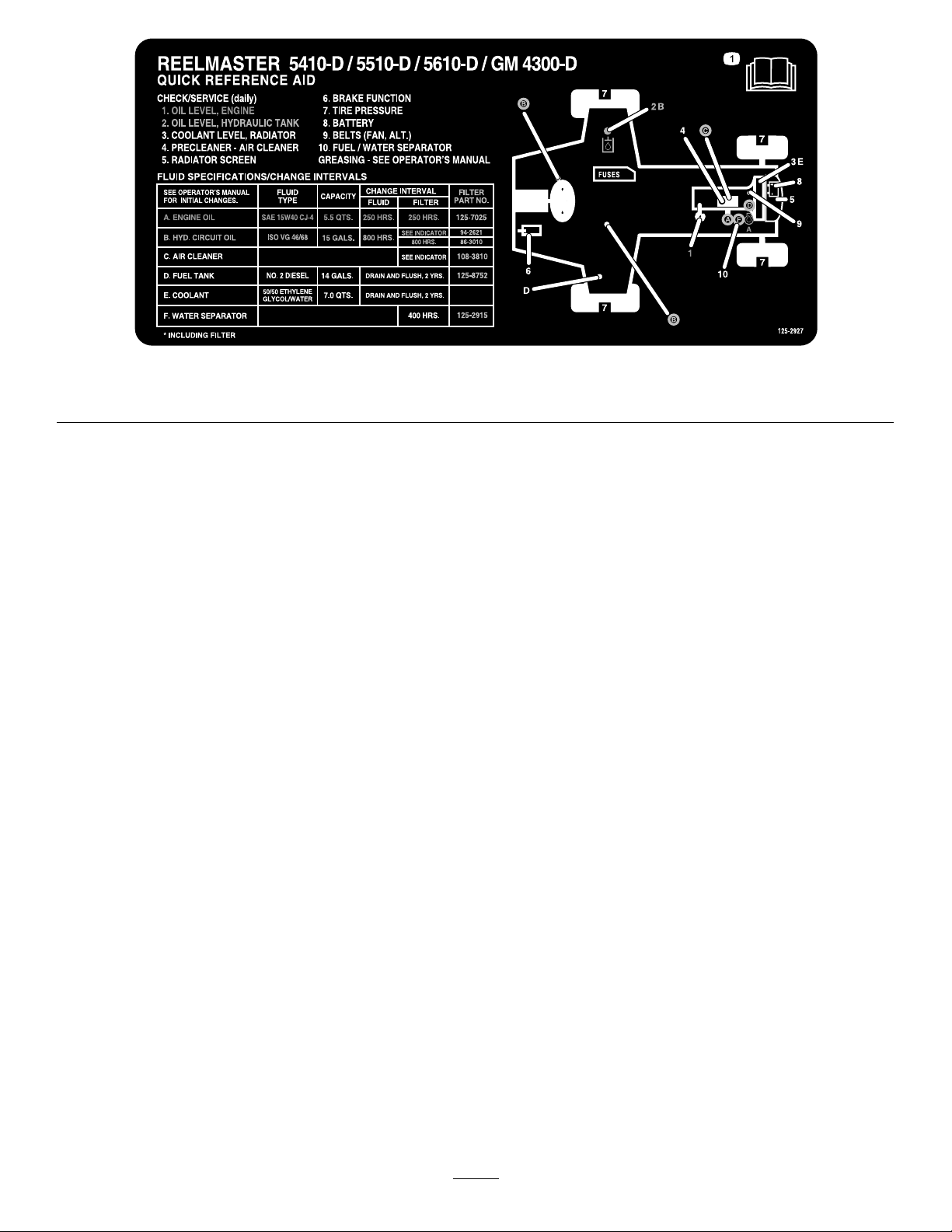
1.ReadtheOperator’sManualformaintenanceinformation.
decal125-2927
125–2927
11
Page 12

Setup
LooseParts
Usethechartbelowtoverifythatallpartshavebeenshipped.
ProcedureDescription
1
2
3
4
5
6
MediaandAdditionalParts
Description
Operator'sManual
EngineOperator'sManual
PartsCatalog
Nopartsrequired
Nopartsrequired
Nopartsrequired
Fronthoseguide-R.H.1
Fronthoseguide-L.H.1
Nopartsrequired
Cuttingunitkickstand
Qty.
1
1
1
ReadtheOperator'sManualbeforeoperatingthemachine.
Usetoreferenceengineinformation
Usetoreferencepartnumbers
Qty.
Use
–
–
–
–
1
Adjustthetirepressure.
Adjustthestepheight.
Adjustthecontrolarmposition.
Installthecuttingunits
Adjusttheturfcompensationspring.
InstalltheCuttingUnitKickstand.
Use
OperatorTrainingMaterial
CuttingPerformancePaper
Shim
Note:Determinetheleftandrightsidesofthe
machinefromthenormaloperatingposition.
1
1
1
Reviewbeforeoperatingthemachine
Usedforadjustingthecuttingunitbedknifetoreel
Usedforadjustingthecuttingunitbedknifetoreel
12
Page 13
1
AdjustingtheTirePressure
2.Raiseorlowerthesteptothedesiredheight
andre-securethebracketstotheframewiththe
2boltsandnuts.
3.Repeattheprocedureontheotherstep.
NoPartsRequired
Procedure
Thetiresareover-inatedforshipping.Therefore,
releasesomeoftheairtoreducethepressure.
Correctairpressureinthefrontandreartiresis83
to103kPa(12to15psi).
Important:Maintainevenpressureinalltiresto
ensureuniformcontactwiththeturf.
2
AdjustingtheStepHeight
NoPartsRequired
Procedure
3
AdjustingtheControlArm Position
NoPartsRequired
Procedure
Thecontrolarmpositioncanbeadjustedforthe
operatorscomfort.
1.Loosenthe2boltssecuringthecontrolarmto
theretainingbracket(Figure3).
Theheightofthestepscanbeadjustedforthe
operatorscomfort.
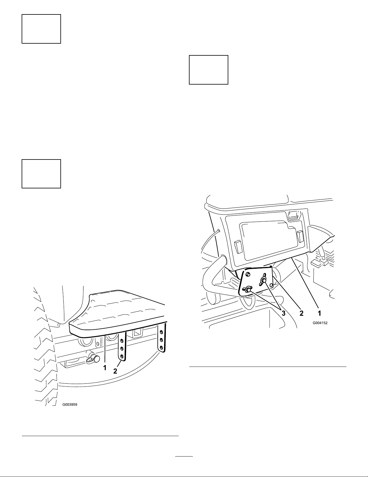
1.Removethe2boltsandnutssecuringthestep
bracketstothetractionunitframe(Figure2)
Figure2
1.Step2.Stepbrackets
g004152
Figure3
1.Controlarm
2.Retainingbrackets
2.Rotatethecontrolarmtothedesiredposition
andtightenthe2bolts.
g003959
3.Bolts(2)
13
Page 14
4
InstallingtheCuttingUnits
Partsneededforthisprocedure:
g003949
Figure5
1Fronthoseguide-R.H.
1Fronthoseguide-L.H.
Procedure
1.Removethereelmotorsfromtheshipping
brackets.
2.Removetheshippingbracketsanddiscard.
3.Removethecuttingunitsfromthecartons.
Assembleandadjustasdescribedinthecutting
unitOperator'sManual.
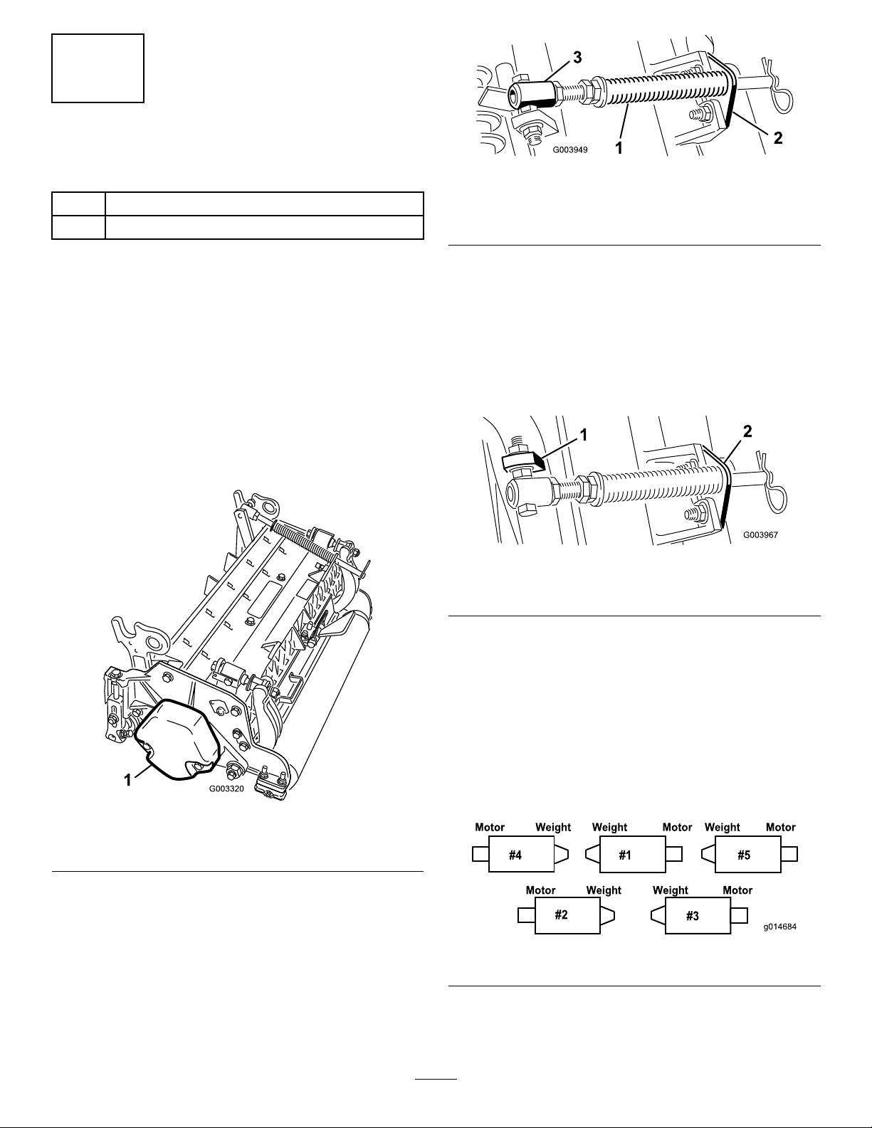
4.Makesurethecounterweight(Figure4)is
installedtotheproperendofthecuttingunitas
describedinthecuttingunitOperator'sManual.
1.Turfcompensationspring3.Springtube
2.Rodbracket
B.Removetheangenutsecuringthespring
tubebolttothecarrierframetab(Figure5)
Removetheassembly.
C.Mountthespringtubebolttotheopposite
tabonthecarrierframeandsecurewiththe
angenut.Theboltheadistobepositioned
totheoutersideofthetabasshownin
Figure6.
Figure6
1.Oppositecarrierframetab
2.Rodbracket
g003967
Figure4
1.Counterweight
5.Allthecuttingunitsareshippedwiththeturf
compensationspringmountedtotherightside
ofthecuttingunit.Theturfcompensationspring
mustbemountedtothesamesideofthecutting
unitasthereeldrivemotor.Repositiontheturf
compensationasfollows:
A.Removethe2carriageboltsandnuts
securingtherodbrackettothecuttingunit
tabs(Figure5).
D.Mounttherodbrackettothecuttingunit
tabswiththecarriageboltsandnuts(Figure
6).
Important:Onthe#4(leftfront)and
#5(rightfront)cuttingunits(Figure7),
usetherodbracketmountingnutsto
installthehoseguidestothefrontofthe
cuttingunittabs(Figure8).Thehose
guidesshouldleantowardthecenter
g003320
cuttingunit(Figure8andFigure9).
g014684
Figure7
14
Page 15
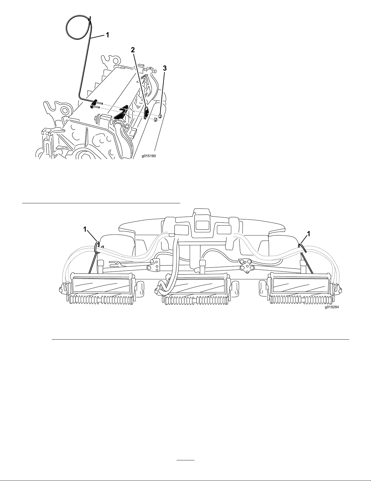
Figure8
g015160
1.Hoseguide(#4cuttingunit
shown)
2.Rodbracket
1.Hoseguides(eachmustleantowardthecentercuttingunit)
3.Nuts
Note:Wheninstallingorremovingthe
cuttingunits,makesurethehairpincotter
isinstalledinthespringrodholenextto
therodbracket.Whennotinstallingor
removingthecuttingunits,thehairpincotter
mustbeinstalledintheholeintheendof
therod.
g019284
Figure9
6.Loweralltheliftarmscompletely .
7.Removethesnapperpinandthecapfromthe
liftarmpivotyoke(Figure10).
15
Page 16
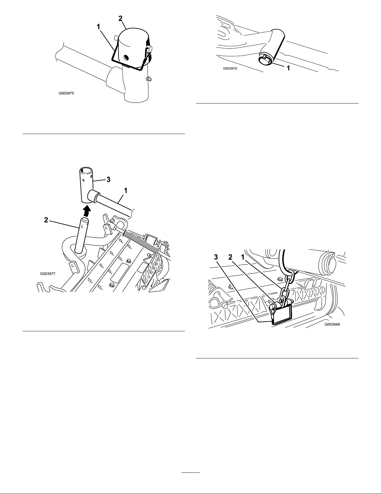
Figure10
1.Snapperpin2.Cap
8.Forthefrontcuttingunits,slideacuttingunit
undertheliftarmwhileinsertingthecarrierframe
shaftupintotheliftarmpivotyoke(Figure11).
g003979
Figure12
1.Liftarmpivotshaftlynchpinandwasher
g003975
B.Inserttheliftarmyokeontothecarrier
frameshaft(Figure1 1).
C.Inserttheliftarmshaftintotheliftarmand
secureitwiththewasherandlynchpin
(Figure12).
10.Insertthecapoverthecarrierframeshaftand
liftarmyoke.
11.Securethecapandthecarrierframeshaftto
theliftarmyokewiththesnapperpin.Usethe
slotifasteeringcuttingunitisdesiredorusethe
holeifthecuttingunitistobelockedinposition
(Figure10).
12.Securetheliftarmchaintothechainbracket
withthesnapperpin(Figure13).Usethe
numberofchainlinksdescribedinthecutting
unitOperator'sManual.
Figure11
1.Liftarm3.Liftarmpivotyoke
2.Carrierframeshaft
9.Usethefollowingprocedureontherearcutting
unitswhentheheightofcutisabove3/4inch.
A.Removethelynchpinandwashersecuring
theliftarmpivotshafttotheliftarmand
slidetheliftarmpivotshaftoutoftheliftarm
(Figure12).
g003977
g003948
Figure13
1.Liftarmchain2.Chainbracket
13.Onthe#4(leftfront)and#5(rightfront)cutting
units,insertthereelmotorhosesintothe
respectivehoseguide.
14.Coatthesplineshaftofthereelmotorwithclean
grease.
15.OilthereelmotorO-ringandinstallitontothe
motorange.
16.Installthemotorbyrotatingitclockwisesothat
themotorangesclearthebolts(Figure14).
Rotatethemotorcounterclockwiseuntilthe
angesencircletheboltsthentightenthebolts.
16
Page 17
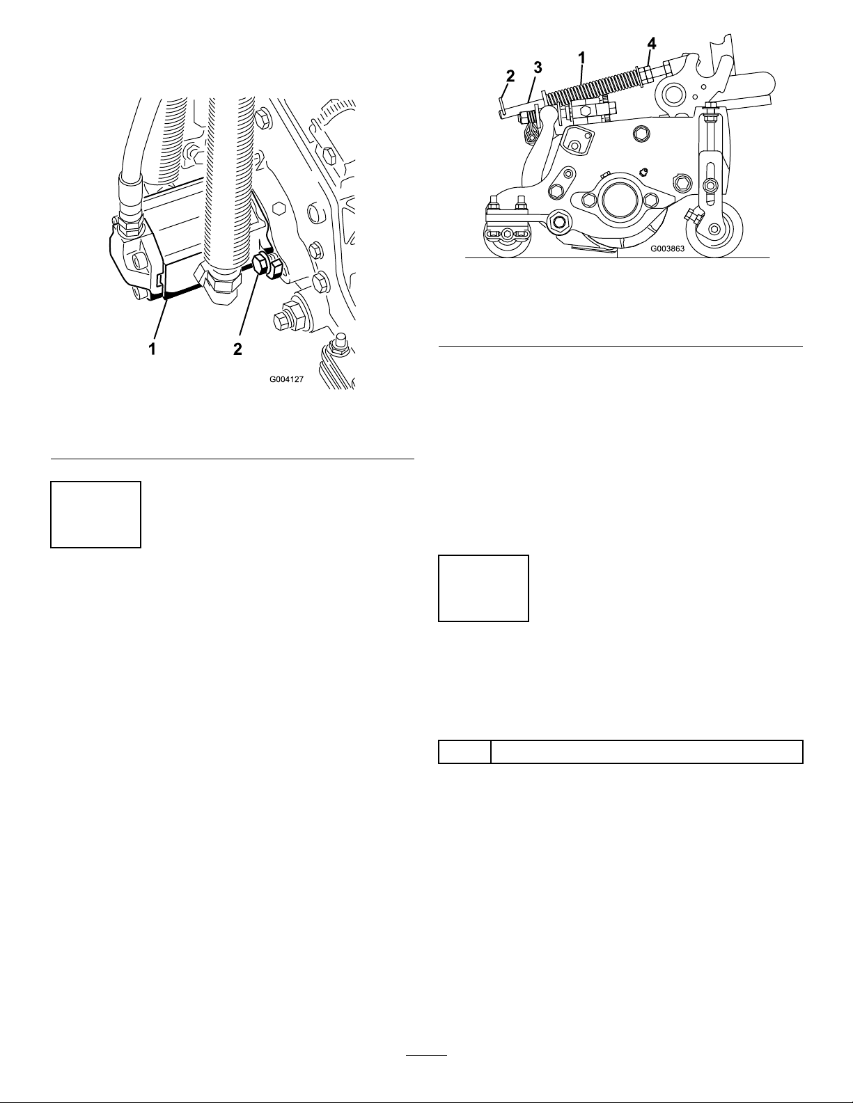
Important:Makesurethereelmotorhoses
arenottwisted,kinkedorintheriskofbeing
pinched.
Figure14
1.Reeldrivemotor2.Mountingbolts
g003863
Figure15
1.Turfcompensationspring3.Springrod
2.Hairpincotter4.Hexnuts
2.Tightenthehexnutsonthefrontendofthe
g004127
springroduntilthecompressedlengthofthe
springis12.7cm(5inches)onReelmaster
5410,5inchcuttingunitsor15.9cm(6.25
inches)onReelmaster5510,7inchcuttingunits
(Figure15).
5
AdjustingtheTurf CompensationSpring
NoPartsRequired
Procedure
Theturfcompensationspring(Figure15)transfers
weightfromthefronttotherearroller.(Thishelps
toreduceawavepatternintheturf,alsoknownas
marcellingorbobbing.)
Important:Makespringadjustmentswiththe
cuttingunitmountedtothetractionunit,pointing
straightaheadandloweredtotheshopoor.
1.Makesurethehairpincotterisinstalledinthe
rearholeinthespringrod(Figure15).
Note:Whenoperatingonroughterrain
decreasethespringlengthby12.7mm
(1/2inch).Groundfollowingwillbeslightly
decreased.
6
UsingtheCuttingUnit Kickstand
Partsneededforthisprocedure:
1
Cuttingunitkickstand
Procedure
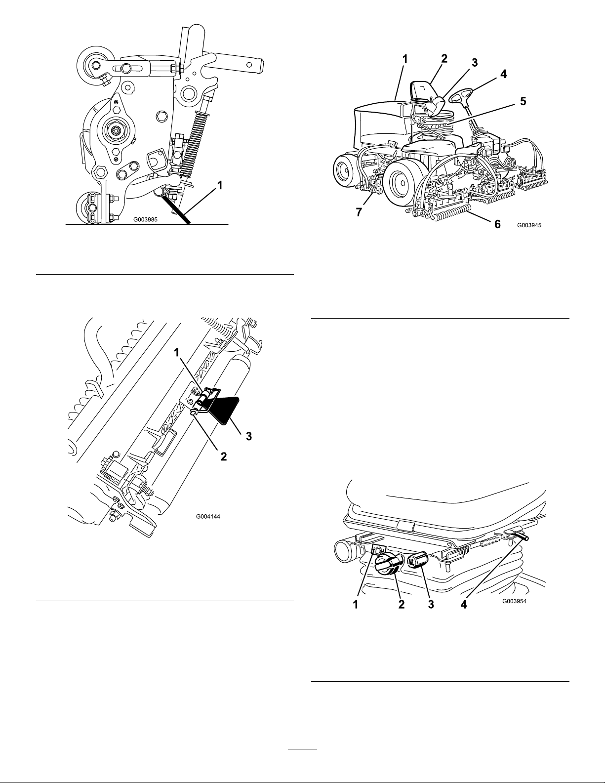
Wheneverthecuttingunithastobetippedtoexpose
thebedknife/reel,propuptherearofthecuttingunit
withthekickstandtomakesurethenutsontheback
endofthebedbaradjustingscrewsarenotrestingon
theworksurface(Figure16).
17
Page 18
ProductOverview
Figure16
1.Cuttingunitkickstand
Securethekickstandtothechainbracketwiththe
snapperpin(Figure17).
g003985
Figure18
1.Enginehood
2.Operator'sseat
3.Controlarm
4.Steeringwheel
5.Seat
6.Frontcuttingunits
7.Rearcuttingunits
g003945
Controls
SeatAdjustingKnobs
Theseatadjustinglever(Figure19)allowsyouto
adjusttheseatforeandaft.Theweightadjusting
knobadjuststheseatfortheoperator'sweight.The
weightgaugeindicateswhentheseatisadjustedto
theweightoftheoperator.Theheightadjustingknob
adjuststheseatfortheoperator'sheight.
1.Chainbracket
2.Snapperpin
Figure17
3.Cuttingunitkickstand
g004144
g003954
Figure19
1.Weightgauge3.Heightadjustingknob
2.Weightadjustingknob
18
4.Adjustinglever(foreand
aft)
Page 19

TractionPedal
TiltSteeringPedal
Thetractionpedal(Figure20)controlstheforwardand
reverseoperation.Pressthetopofthepedaltomove
forwardandthebottomtomoverearward.Ground
speeddependsonhowfaryoupressthepedal.For
noload,maximumgroundspeed,fullypressthepedal
whiletheenginespeedsettingisintheFastposition.
Tostop,reducefootpressureonthetractionpedal
andallowittoreturntothecenterposition.
Totiltthesteeringwheeltowardsyou,pressthefoot
pedal(Figure20)down,andpullthesteeringtower
towardyoutothemostcomfortablepositionandthen
releasethepedal.
EngineSpeedSwitch
Theenginespeedswitch(Figure21)hastwomodes
tochangetheenginespeed.Bymomentarilytapping
theswitch,theenginespeedcanbeincreasedor
decreasedin100rpmincrements.Byholdingthe
switchdowntheenginewillautomaticallymoveto
HighorLowidle,dependingonwhichendofthe
switchisdepressed.
Figure20
1.Tractionpedal4.Brakepedal
2.Mowspeedlimiter5.Parkingbrake
3.Spacers
6.Tiltsteeringpedal
MowSpeedLimiter
Whenthemowspeedlimiter(Figure20)isippedup
itwillcontrolthemowspeedandallowthecutting
unitstobeengaged.Eachspaceradjuststhemowing
speedby.8kph(½mileperhour).Themorespacers
youhaveonthetopofthebolt,thesloweryouwillgo.
Fortransport,ipbackthemowspeedlimiterandyou
willhavemaximumtransportspeed.
BrakePedal
Pressthebrakepedal(Figure20)tostopthemachine.
ParkingBrake
Toengagetheparkingbrake,(Figure20)pushdown
onthebrakepedalandpressthetopforwardtolatch.
Toreleasetheparkingbrake,pressthebrakepedal
untiltheparkingbrakelatchretracts.
g003955
g021208
Figure21
1.Lowermow/raisecontrol
lever
2.Keyswitch5.Enginespeedswitch
3.InfoCenter
4.Enable/disableswitch
6.Headlightswitch
Enable/DisableSwitch
Usetheenable/disableswitch(Figure21)in
conjunctionwiththelowermow/raisecontrolleverto
operatethecutterheads.
InfoCenter
TheInfoCenterLCDdisplayshowsinformationabout
yourmachinesuchastheoperatingstatus,various
diagnosticsandotherinformationaboutthemachine
(Figure21).
KeySwitch
Thekeyswitch(Figure21)hasthreepositions:Off,
On/Run,andStart.
19
Page 20

LowerMow/RaiseControlLever
HydraulicFilterRestriction
Thislever(Figure21)raisesandlowersthecutting
unitsandalsostartsandstopsthecutterheads
whenthecutterheadsareenabledinthemowmode.
Thecutterheadscannotbeloweredwhenthe
mow/transportleverisinthetransportposition.
HeadlightSwitch
Pivottheswitchdownwardtoturnontheheadlights
(Figure21).
BacklapLevers
Usethebacklapleversinconjunctionwiththelower
mow/raisecontrolleverforbacklappingthereels
(Figure22).
Indicator
Withtheenginerunningatnormaloperating
temperature,viewtheindicator(Figure23),itshould
beintheGreenzone.Whentheindicatorisinthe
Redzone,changethehydrauliclters.
g004132
Figure23
1.Hydrauliclterrestrictionindicator
1.Backlaplevers
PowerPoint
Thepowerpointisa12voltpowersupplyfor
electronicdevices(Figure24).
g021209
Figure22
g004133
Figure24
1.Powerpoint
20
Page 21

UsingtheInfoCenterLCDDisplay
InfoCenterIconDescription
TheInfoCenterLCDdisplayshowsinformationabout
yourmachine,suchastheoperatingstatus,various
diagnostics,andotherinformationaboutthemachine
(Figure25).Thereisasplashscreenandmain
informationscreenoftheInfoCenter.Y oucanswitch
betweenthesplashscreenandmaininformation
screen,atanytime,bypressinganyoftheInfoCenter
buttonsandthenselectingtheappropriatedirectional
arrow.
Figure25
SERVICEDUE
g020650
Indicateswhenscheduledservice
shouldbeperformed
Enginerpm/status—indicatesthe
enginespeed(rpm)
Hourmeter
Infoicon
Fast
Slow
Fuellevel
Stationaryregenerationrequired
Glowplugsareactive
Raisecuttingunits
1.Indicatorlight3.Middlebutton
2.Rightbutton
4.Leftbutton
•LeftButton,MenuAccess/BackButton—Pressthis
buttontoaccesstheInfoCentermenus.Youcan
useittobackoutofanymenuyouarecurrently
using.
•MiddleButton—Usethisbuttontoscrolldown
menus.
•RightButton—Usethisbuttontoopenamenu
wherearightarrowindicatesadditionalcontent.
Note:Thepurposeofeachbuttonmaychange
dependingonwhatisrequiredatthetime.Each
buttonwillbelabeledwithanicondisplayingits
currentfunction.
Lowercuttingunits
Operatormustsitinseat
Parking-BrakeIndicator—indicates
whentheparkingbrakeisOn
IdentiestherangeasHigh
(Transport)
Neutral
IdentiestherangeasLow(Mow)
CoolantTemperature—indicatesthe
engine-coolanttemperatureineither
°Cor°F
Temperature(hot)
PTOisengaged
Deniedornotallowed
Enginestart
Stoporshutdown
21
Page 22

InfoCenterIconDescription(cont'd.)
Symbolsareoften
combinedtoform
sentences.Some
examplesareshown
below
Engine
Keyswitch
Indicateswhenthecuttingunitsare
beinglowered
Indicateswhenthecuttingunitsare
beingraised
PINcode
CANbus
InfoCenter
Badorfailed
Bulb
OutputofTECcontrollerorcontrol
wireinharness
Switch
Operatormustreleaseswitch
Operatorshouldchangetoindicated
state
Operatorshouldputmachinein
neutral
Enginestartdenied
Engineshutdown
Enginecoolanttoohot
DPFash-accumulation
notication—RefertoServicing
theDiesel-OxidationCatalyst(DOC)
andtheSootFilter(page48)for
details.
Sitdownorsetparkingbrake
UsingtheMenus
ToaccesstheInfoCentermenusystem,pressthe
menuaccessbuttonwhileatthemainscreen.This
willbringyoutothemainmenu.Refertothefollowing
tablesforasynopsisoftheoptionsavailablefrom
themenus:
MainMenu
MenuItemDescription
Faults
ServiceContainsinformationonthe
Diagnostics
Settings
AboutListsthemodelnumber,serial
Service
MenuItemDescription
Hours
Counts
Diagnostics
MenuItemDescription
CuttingUnitsIndicatestheinputs,qualiers
Hi/LowRangeIndicatestheinputs,qualiers
PTOIndicatestheinputs,qualiers
Containsalistoftherecent
machinefaults.Referto
theServiceManualoryour
AuthorizedToroDistributorfor
moreinformationontheFaults
menuandtheinformation
containedthere.
machinesuchashoursof
usecountersandothersimilar
numbers.
Displaysthestateofeach
machineswitch,sensorand
controloutput.Y oucanuse
thistotroubleshootcertain
issuesasitwillquicklytellyou
whichmachinecontrolsareon
andwhichareoff.
Allowsyoutocustomizeand
modifycongurationvariables
ontheInfoCenterdisplay.
number,andsoftwareversion
ofyourmachine.
Liststhetotalnumberofhours
thatthemachine,engineand
PTOhavebeenon,aswell
asthenumberofhoursthe
machinehasbeentransported
andservicedue.
Listsnumerouscountsthe
machinehasexperienced.
andoutputsforraisingand
loweringthecuttingunits.
andoutputsfordrivingin
transportmode.
andoutputsforenablingthe
PTOcircuit.
22
Page 23

EngineRun
Backlap
Settings
MenuItemDescription
Units
Language
LCDBacklightControlsthebrightnessofthe
LCDContrastControlsthecontrastofthe
FrontBacklapReelSpeedControlsthespeedofthefront
RearBacklapReelSpeedControlsthespeedoftherear
ProtectedMenusAllowsapersonauthorized
AutoIdle
BladeCountControlsthenumberofblades
MowSpeedControlsthegroundspeedfor
Heightofcut(HOC)Controlstheheightofcut
FReelRPMDisplaysthecalculatedreel
RReelRPMDisplaysthecalculatedreel
Indicatestheinputs,qualiers
andoutputsforstartingthe
engine.
Indicatestheinputs,qualiers
andoutputsforoperatingthe
backlapfunction.
Controlstheunitsusedonthe
InfoCenter.Themenuchoices
areEnglishorMetric
Controlsthelanguageused
ontheInfoCenter*.
LCDdisplay.
LCDdisplay.
reelsinbacklapmode.
reelsinbacklapmode.
byyourcompanywiththe
PINcodetoaccessprotected
menus.
Controlstheamountoftime
allowedbeforereturningthe
enginetolowidlewhenthe
machineisstationary.
onthereelforreelspeed.
determiningthereelspeed.
(HOC)fordeterminingthereel
speed.
speedpositionforthefront
reels.Thereelscanalsobe
manuallyadjusted.
speedpositionfortherear
reels.Thereelscanalsobe
manuallyadjusted.
*Only"operator-faced"textistranslated.Faults,
Service,andDiagnosticsscreensare"service-faced."
Titlesappearintheselectedlanguage,butmenu
itemsareinEnglish.
Machine-ControllerRevisionListsthesoftwarerevisionof
InfoCenterRevisionListsthesoftwarerevisionof
CANBus
themastercontroller .
theInfoCenter.
Liststhemachine
communicationbusstatus.
ProtectedMenus
Thereare8operatingcongurationsettingsthatare
adjustablewithintheSettingsMenuoftheInfoCenter:
autoidletimedelay ,BladeCount,MowSpeed,Height
ofCut(HOC),FReelRPMandRReelRPM.These
settingscanbelockedbyusingtheProtectedMenu.
Note:Atthetimeofdelivery,theinitialpassword
codeisprogrammedbyyourdistributor.
AccessingProtectedMenus
Note:ThefactorydefaultPINcodeforyoumachine
iseither0000or1234.
IfyouchangedthePINcodeandforgotthe
code,contactyourAuthorizedToroDistributorfor
assistance.
1.FromtheMAINMENU,usethecenterbuttonto
scrolldowntotheSETTINGSMENUandpressthe
rightbutton(Figure26).
Figure26
2.IntheSETTINGSMENU,usethecenterbuttonto
scrolldowntothePROTECTEDMENUandpress
therightbutton(Figure27A).
g028523
About
MenuItemDescription
Model
SNListstheserialnumberofthe
Liststhemodelnumberofthe
machine.
machine.
23
Page 24

Figure27
3.T oenterthePINcode,pressthecenterbutton
untilthecorrectrstdigitappears,thenpress
therightbuttontomoveontothenextdigit
(Figure27BandFigure27C).Repeatthisstep
untilthelastdigitisenteredandpresstheright
buttononcemore.
4.PressthemiddlebuttontoenterthePINcode
(Figure27D).
ToSettheAutoIdle
•IntheSettingsMenu,scrolldowntoAutoIdle.
•Presstherightbuttontochangetheautoidletime
betweenOFF ,8S,10S,15S,20S,&30S.
ToSettheBladeCount
•IntheSettingsMenu,scrolldowntoBladeCount
•Presstherightbuttontochangethebladecount
between5,8or11bladereels.
ToSettheMowSpeed
•IntheSettingsMenu,scrolldowntoMowSpeed.
•Presstherightbuttontoselectmowspeed.
•Usethecenterandrightbuttontoselectthe
appropriatemowspeedsetonthemechanical
mowspeedlimiteronthetractionpedal.
•Presstheleftbuttontoexitmowspeedandsave
g028522
thesetting.
ToSettheHeightofCut(HOC)
•IntheSettingsMenu,scrolldowntoHOC.
•PresstherightbuttontoselectHOC.
•Usethecenterandrightbuttontoselectthe
appropriateHOCsetting.(Iftheexactsettingis
notdisplayed,selectthenearestHOCsettingfrom
thelistdisplayed).
•PresstheleftbuttontoexitHOCandsavethe
setting.
WaituntiltheredindicatorlightoftheInfoCenter
illuminates.
Note:IftheInfoCenteracceptsthePINcode
andtheprotectedmenuisunlocked,theword
“PIN”displaysintheupperrightcornerofthe
screen.
Note:RotatethekeyswitchtotheOFFpositionand
thentotheONpositionlockstheprotectedmenu.
Youhavetheabilitytoviewandchangethesettingsin
theProtectedMenu.OnceyouaccesstheProtected
Menu,scrolldowntoProtectSettingsoption.Usethe
rightbuttontochangethesetting.SettingtheProtect
SettingstoOFFallowsyoutoviewandchangethe
settingsintheProtectedMenuwithoutenteringthe
PINcode.SettingtheProtectSettingstoONhidesthe
protectedoptionsandrequiresyoutoenterthePIN
codetochangethesettingintheProtectedMenu.
AfteryousetthePINcode,rotatethekeyswitchOFF
andbacktotheONpositiontoenableandsavethis
feature.
ToSettheFrontandRearReel
Speeds
Althoughthefrontandrearreelspeedsarecalculated
byinputtingthenumberofblades,mowspeedand
HOCintotheInfoCenter,thesettingcanbemanually
changedtoaccommodatefordifferentmowing
conditions.
•T ochangetheReelSpeedSettings,scrolldownto
theFReelRPM,RReelRPMorboth.
•Presstherightbuttontochangethereelspeed
value.Asthespeedsettingischanged,thedisplay
willcontinuetoshowthecalculatedreelspeed
basedonbladecount,mowspeedandHOCwhich
waspreviouslyentered,butthenewvaluewillalso
bedisplayed.
ToTurnSmartPowerON/OFF
•Inthesettingsmenu,scrolldowntoSmartPower.
•PresstherightbuttontoswitchbetweenONand
OFF.
•Presstheleftbuttontoexit.
24
Page 25

Specications
Note:Specicationsanddesignaresubjectto
changewithoutnotice.
SpecicationReelMaster®5410-DReelMaster®5510-D
TransportWidth
Widthofcut254cm(100inches)254cm(100inches)
Length
Height
Weight
(withuidsand8bladecuttingunitsinstalled)
EngineYanmar
Fueltankcapacity
228cm(90inches)233cm(92inches)
282cm(111inches)282cm(111inches)
160cm(63inches)160cm(63inches)
1,335kg(2,943lb)1,420kg(3,131lb)
36hp
53liters(14USgallons)53liters(14USgallons)
Yanmar
36hp
Transportspeed
Mowingspeed
Attachments/Accessories
AselectionofToroapprovedattachmentsand
accessoriesisavailableforusewiththemachineto
enhanceandexpanditscapabilities.Contactyour
AuthorizedServiceDealerorDistributororgoto
www.T oro.comforalistofallapprovedattachments
andaccessories.
0–16kph(0–10mph)0–16kph(0–10mph)
0–13kph(0–8mph)0–13kph(0–8mph)
Operation
Note:Determinetheleftandrightsidesofthe
machinefromthenormaloperatingposition.
CAUTION
Ifyouleavethekeyintheignitionswitch,
someonecouldaccidentlystarttheengine
andseriouslyinjureyouorotherbystanders.
Lowerthecuttingunitstotheground,setthe
parkingbrakeandremovethekeyfromthe
ignitionswitchbeforeservicingormaking
adjustmentstothemachine.
CheckingtheEngine-Oil Level
Beforeyoustarttheengineandusethemachine,
checktheoillevelintheenginecrankcase;referto
CheckingtheEngine-OilLevel(page47).
25
Page 26

FillingtheFuelTank
DANGER
Incertainconditions,fuelisextremely
ammableandhighlyexplosive.Areor
explosionfromfuelcanburnyouandothers
andcandamageproperty.
WARNING
Fuelisharmfulorfatalifswallowed.
Long-termexposuretovaporscancause
seriousinjuryandillness.
•Avoidprolongedbreathingofvapors.
•Keepyourfaceawayfromthenozzleand
fueltankopening.
•Fillthefueltanksoutdoors,inanopen
area,whentheengineiscold.Wipeupany
fuelthatspills.
•Neverllthefueltanksinsideanenclosed
trailer.
•Neversmokewhenhandlingfuelandstay
awayfromanopenameorwherefuel
fumesmaybeignitedbyaspark.
•Storefuelinanapprovedcontainerand
keepitoutofthereachofchildren.Never
buymorethana30-daysupplyoffuel.
•Donotoperatewithoutentireexhaust
systeminplaceandinproperworking
condition.
DANGER
Incertainconditionsduringfueling,static
electricitycanbereleased,causingaspark
thatcanignitethefuelvapors.Areor
explosionfromfuelcanburnyouandothers
andcandamageproperty.
•Alwaysplacefuelcontainersontheground
awayfromyourvehiclebeforelling.
•Donotllfuelcontainersinsideavehicle
oronatruckortrailerbed,becauseinterior
carpetsorplastictruckbedlinersmay
insulatethecontainerandslowthelossof
anystaticcharge.
•Whenpractical,removeequipmentfrom
thetruckortrailerandrefueltheequipment
withitswheelsontheground.
•Ifthisisnotpossible,thenrefuelsuch
equipmentonatruckortrailerfroma
portablecontainerratherthanfroma
fuel-dispensernozzle.
•Ifyoumustuseafuel-dispensernozzle,
keepthenozzleincontactwiththerimof
thefueltankorcontaineropeningatall
timesuntilfuelingiscomplete.
•Keepfuelawayfromyoureyesandskin.
FuelSpecication
Important:Useonlyultra-lowsulphurdiesel
fuel.Fuelwithhigherratesofsulfurdegrades
thedieseloxidationcatalyst(DOC),whichcauses
operationalproblemsandshortenstheservicelife
ofenginecomponents.
Failuretoobservethefollowingcautionsmay
damagetheengine.
•Neverusekeroseneorgasolineinsteadofdiesel
fuel.
•Nevermixkeroseneorusedengineoilwiththe
dieselfuel.
•Neverkeepfuelincontainerswithzincplatingon
theinside.
•Donotusefueladditives.
PetroleumDiesel
Cetanerating:45orhigher
Sulfurcontent:Ultra-lowsulfur(<15ppm)
FuelTable
Dieselfuelspecication
ASTMD975
No.1-DS15
No.2-DS15
EN590EuropeanUnion
ISO8217DMX
JISK2204GradeNo.2
KSM-2610
•Useonlyclean,freshdieselfuelorbiodieselfuels.
•Purchasefuelinquantitiesthatcanbeusedwithin
180daystoensurefuelfreshness.
Usesummer-gradedieselfuel(No.2-D)at
temperaturesabove-7°C(20°F)andwinter-grade
fuel(No.1-DorNo.1-D/2-Dblend)belowthat
temperature.
Note:Useofwinter-gradefuelatlowertemperatures
provideslowerashpointandcoldowcharacteristics
whicheasesstartingandreducesfuellterplugging.
Location
USA
International
Japan
Korea
26
Page 27

Usingsummer-gradefuelabove-7°C(20°F)
contributestowardlongerfuelpumplifeandincreased
powercomparedtowinter-gradefuel.
Biodiesel
Thismachinecanalsouseabiodieselblendedfuelof
uptoB20(20%biodiesel,80%petroleumdiesel).
Sulfurcontent:Ultra-lowsulfur(<15ppm)
Biodieselfuelspecication:ASTMD6751or
EN14214
Blendedfuelspecication:ASTMD975,EN590,
orJISK2204
Important:Thepetroleumdieselportionmust
beultra-lowsulfur.
Observethefollowingprecautions:
•Biodieselblendsmaydamagepaintedsurfaces.
•UseB5(biodieselcontentof5%)orlesserblends
incoldweather.
•Monitorseals,hoses,gasketsincontactwithfuel
astheymaybedegradedovertime.
•Fuellterpluggingmaybeexpectedforatime
afterconvertingtobiodieselblends.
•ContactyourAuthorizedT oroDistributorifyou
wishformoreinformationonbiodiesel.
FuelTankCapacity
Note:Ifpossible,llthefueltankaftereachuse.
Thisminimizespossiblebuildupofcondensation
insidethefueltank.
CheckingtheCooling System
Cleandebrisoffofthescreen,oilcooler,andfront
oftheradiatordailyandmoreoftenifconditionsare
extremelydustyanddirty.Refertothesectionon
RemovingDebrisfromtheCoolingSystem.
Thecoolingsystemislledwitha50/50solution
ofwaterandpermanentethyleneglycolantifreeze.
Checkthelevelofcoolantintheexpansiontankatthe
beginningofeachdaybeforestartingtheengine.The
capacityofthecoolingsystemis6.6liters(7.0quarts).
CAUTION
Iftheenginehasbeenrunning,the
pressurized,hotcoolantcanescapeand
causeburns.
•Donotopentheradiatorcapwhenthe
engineisrunning.
•Usearagwhenopeningtheradiatorcap,
andopenthecapslowlytoallowsteamto
escape.
53L(14USgallons)
AddingFuel
1.Parkthemachineonalevelsurface.
2.Usingacleanrag,cleanareaaroundfuel-tank
cap.
3.Removethecapfromthefueltank(Figure28).
Figure28
1.Fuel-tankcap
4.Fillthetankuntilthelevelis6to13mm(1/4to
1/2inch)belowthebottomofthellerneck.
5.Installthefuel-tankcaptightlyafterllingthe
tank.
1.Checkthelevelofcoolantintheexpansiontank
(Figure29).
Thecoolantlevelshouldbebetweenthemarks
onthesideofthetank.
g021210
1.Expansiontank
2.Ifthecoolantlevelislow,removetheexpansion
tankcapandreplenishthesystem.Donot
overll.
3.Installtheexpansiontankcap.
Figure29
g021866
27
Page 28

CheckingtheHydraulic Fluid
ServiceInterval:Beforeeachuseordaily
Themachinesreservoirislledatthefactorywith
approximately30L(8USgallons)ofhigh-quality
hydraulicuid.Checkthelevelofthehydraulicuid
beforetheengineisrststartedanddailythereafter.
Therecommendedreplacementuidisasfollows:
Important:Manyhydraulicuidsarealmost
colorless,makingitdifculttospotleaks.A
reddyeadditiveforthehydraulicsystemoilis
availablein20ml(2/3oz)bottles.1bottleis
sufcientfor15to22L(4to6gallons)ofhydraulic
oil.OrderPartNumber44-2500fromyourT oro
Distributor.Thisreddyeisnotrecommendedfor
usewithbiodegradableuids.Usefoodcoloring.
1.Positionthemachineonalevelsurface,lower
thecuttingunits,andstoptheengine.
ToroPremiumAllSeasonHydraulicFluid(Availablein
19L(5USgallon)pailsor208L(55USgallon)drums.See
thePartsCatalogoryourT oroDistributorforpartnumbers.)
Alternateuids:IftheT orouidisnotavailable,other
uidsmaybeusedprovidedtheymeetallthefollowing
materialpropertiesandindustryspecications.We
donotrecommendtheuseofsyntheticuid.Consult
withyourlubricantdistributortoidentifyasatisfactory
product.
Note:T orodoesnotassumeresponsibilityfor
damagecausedbyimpropersubstitutions,souse
onlyproductsfromreputablemanufacturerswho
standbehindtheirrecommendation.
HighViscosityIndex/LowPourPointAnti-wearHydraulic
Fluid,ISOVG46
MaterialProperties:
Viscosity,ASTMD445cSt@40°C44to50
ViscosityIndexASTMD2270
PourPoint,ASTMD97-36.6°C(-34°F)to9.4°C
IndustrySpecications:
VickersI-286-S(QualityLevel),VickersM-2950-S(Quality
Level),DenisonHF-0
cSt@100°C7.9to8.5
140to160
(-49°F)
Important:TheISOVG46Multigradeuid
hasbeenfoundtoofferoptimalperformance
inawide-rangeoftemperatureconditions.
Foroperationinconsistentlyhighambient
temperatures,18°C(65°F)to49°C(120°F),
ISOVG68hydraulicuidmayofferimproved
performance.
PremiumBiodegradableHydraulicFluid-Mobil
EALEnviroSyn46H
2.Cleantheareaaroundllerneckandcapofthe
hydraulictank(Figure30).Removethecap
fromthellerneck.
g021215
Figure30
1.Hydraulic-tankcap
3.Removethedipstickfromthellerneckand
wipeitwithacleanrag.
4.Insertthedipstickintothellerneck;then
removeitandchecktheleveloftheuid.
Note:Theuidlevelshouldbewithin6.3mm
(1/4inch)ofthemarkonthedipstick.
Important:Donotoverll.
5.Ifthelevelislow,addappropriateuidtoraise
theleveltotheFULLmark.
6.Installthedipstickandcapontothellerneck.
Important:MobilEALEnviroSyn46Histheonly
syntheticbiodegradableuidapprovedbyToro.
Thisuidiscompatiblewiththeelastomersused
inTorohydraulicsystemsandissuitablefora
wide-rangeoftemperatureconditions.Thisuidis
compatiblewithconventionalmineraloils,butfor
maximumbiodegradabilityandperformancethe
hydraulicsystemshouldbethoroughlyushed
ofconventionaluid.Theoilisavailablein19L
(5USgallon)containersor208L(55USgallon)
drumsfromyourMobilDistributor.
CheckingtheReelto BedknifeContact
Eachdaybeforeoperating,checkreeltobedknife
contact,regardlessifthequalityofcuthadpreviously
beenacceptable.Theremustbelightcontactacross
thefulllengthofthereelandthebedknife(referto
AdjustingtheReeltoBedknifeinthecuttingunit
Operator'sManual).
28
Page 29

ChecktheTorqueofthe
SettingtheReelSpeed
WheelNuts
Torquethewheelnutsto94to122N-m(70to90ft-lb).
after1-4hoursofoperationandagainafter10hours
ofoperation.T orqueevery250hoursthereafter.
WARNING
Failuretomaintainpropertorqueofthewheel
nutscouldresultinpersonalinjury.
StartingandStoppingthe Engine
Important:Thefuelsystemwillautomatically
bleeditselfwhenanyofthefollowingsituations
occur:
•Initialstartupofanewmachine.
•Theenginehasceasedrunningduetolackoffuel.
•Maintenancehasbeenperformeduponthefuel
systemcomponents.
StartingtheEngine
1.Sitontheseat,keepyourfootoffofthetraction
pedalsothatitisinNeutral,engagetheparking
brake,settheenginespeedswitchtotheMid
positionandensurethattheEnable/Disable
switchisintheDisableposition.
2.Removeyourfootfromthetractionpedaland
makesurethepedalisintheNeutralposition.
3.TurntheignitionkeytotheRunposition.
4.Whentheglowindicatordims,turntheignition
keytotheStartposition.Releasethekey
immediatelywhentheenginestartsandallowit
toreturntotheRunposition.Allowengineto
warmup(withoutload),thenmovethethrottle
controltothedesiredposition.
Toachieveaconsistent,highquality-of-cutanda
uniformaftercutappearance,itisimportantthatyou
setthereelspeedtothepropersetting.Adjustthe
reelspeedasfollows:
1.IntheInfoCenter,underthesettingsmenu,
enterthebladecount,mowspeedandHOCto
calculatetheproperreelspeed.
2.Iffurtheradjustmentsarerequired,inthe
settingsmenu,scrolldowntotheFReelRPM,
RReelRPMorboth.
3.Presstherightbuttontochangethereelspeed
value.Asthespeedsettingischanged,the
displaywillcontinuetoshowthecalculatedreel
speedbasedonbladecount,mowspeedand
HOC,butthenewvaluewillalsobedisplayed.
Note:Thereelspeedmayneedtobeincreased
ordecreasedtocompensateforvaryingturf
conditions.
CuttingGrasswiththe Machine
Note:Cuttinggrassataratethatloadstheengine
promotesDPFregeneration.
1.Movethemachinetothejobsiteandalignthe
machineoutsidethecuttingareafortherst
cuttingpass.
2.EnsurethatthePTOswitchissettotheDISABLE
position.
3.Movetheleverforthemow-speedlimiter
forward.
4.Pressthethrottle-speedswitchtosettheengine
speedtoHIGHIDLE.
5.Usethejoysticktolowerthecuttingunitstothe
ground.
6.PressthePTOswitchtopreparecuttingunits
foroperation.
StoppingtheEngine
1.MoveallcontrolstoNeutral,settheparking
brake,movetheenginespeedswitchtothelow
idlepositionandallowtheenginetoreachlow
idlespeed.
2.TurnthekeytotheOffpositionandremoveit
fromtheswitch.
7.Usethejoysticktoraisethecuttingunitsoffthe
ground.
8.Beginmovingthemachinetowardthecutting
areaandlowerthecuttingunits.
Note:Cuttinggrassataratethatloadsthe
enginepromotesDPFregeneration.
9.Whenyoucompletethemowingpass,usethe
joysticktoliftthecuttingunits.
10.Performatear-shapedturntoquicklylineupfor
yournextpass.
29
Page 30

DieselParticulateFilter Regeneration
Thedieselparticulatelter(DPF)ispartoftheexhaust
system.Thediesel-oxidationcatalystoftheDPF
reducesharmfulgassesandthesootlterremoves
sootfromtheengineexhaust.
TheDPFregenerationprocessusesheatfromthe
engineexhausttoincineratethesootaccumulatedon
thesootlter,convertingthesoottoash,andclears
thechannelsofthesootltersothatlteredengine
exhaustowsouttheDPF .
Theenginecomputermonitorstheaccumulationof
sootbymeasuringthebackpressureintheDPF .If
thebackpressureistoohigh,sootisnotincinerating
inthesootlterthroughnormalengineoperation.T o
keeptheDPFclearofsoot,rememberthefollowing:
•Passiveregenerationoccurscontinuouslywhile
theengineisrunning—runtheengineatfull
enginespeedwhenpossibletopromoteDPF
regeneration.
•Ifthebackpressureistoohigh,theengine
computersignalsyouthroughtheInfoCenter
whenadditionalprocesses(assistandreset
regeneration)arerunning.
•Allowtheassistandresetregenerationprocessto
completebeforeshuttingofftheengine.
Operateandmaintainyourmachinewiththefunction
oftheDPFinmind.Engineloadathighidle
enginespeedgenerallyproduceadequateexhaust
temperatureforDPFregeneration.
Important:Minimizetheamountoftimethatyou
idletheengineoroperatetheengineatlow-engine
speedtohelpreducetheaccumulationofsootin
thesootlter.
CAUTION
Theexhausttemperatureishot(approximately
600°C(1112°F)duringDPFparked
regenerationorrecoveryregeneration.Hot
exhaustgascanharmyouorotherpeople.
•Neveroperatetheengineinanenclosed
area.
•Makesurethattherearenoammable
materialsaroundtheexhaustsystem.
•Nevertouchahotexhaustsystem
component.
•Neverstandnearoraroundtheexhaust
pipeofthemachine.
DPFSootAccumulation
•Overtime,theDPFaccumulatessootinthesoot
lter.Thecomputerfortheenginemonitorsthe
sootlevelintheDPF .
•Whenenoughsootaccumulates,thecomputer
informsyouthatitistimetoregeneratethediesel
particulatelter.
•DPFregenerationisaprocessthatheatstheDPF
toconvertthesoottoash.
•Inadditiontothewarningmessages,thecomputer
reducesthepowerproducedbytheengineat
differentsoot-accumulationlevels.
EngineWarningMessages—SootAccumulation
IndicationLevel
Level1:Engine
Warning
Level2:Engine
Warning
FaultCode
g213866
Figure31
CheckEngine
SPN3719,FMI16
g213867
Figure32
CheckEngine
SPN3719,FMI0
EnginePowerRatingRecommendedAction
Thecomputerde-ratesthe
enginepowerto85%
Thecomputerde-ratesthe
enginepowerto50%
Performaparkedregeneration
assoonaspossible;referto
ParkedRegeneration(page34).
Performarecoveryregeneration
assoonaspossible;referto
RecoveryRegeneration
(page37).
30
Page 31

DPFAshAccumulation
•Thelighterashisdischargedthroughtheexhaust
system;theheavierashcollectsinthesootlter.
•Ashisaresidueoftheregenerationprocess.Over
time,thedieselparticulatelteraccumulatesash
thatdoesnotdischargewiththeengineexhaust.
•Thecomputerfortheenginecalculatestheamount
ofashaccumulatedintheDPF.
InfoCenterAdvisoryandEngineWarningMessages—AshAccumulation
•Whenenoughashaccumulates,theengine
computersendsinformationtotheInfoCenterin
theformofasystemadvisoryoranenginefaultto
indicatetheaccumulationofashintheDPF .
•Theadvisoryandfaultsareindicationsthatitis
timetoservicetheDPF .
•Inadditiontothewarnings,thecomputerreduces
thepowerproducedbytheengineatdifferent
ash-accumulationlevels.
Indication
Level1:
System
Advisory
Level2:
Engine
Warning
Level3:
Engine
Warning
Level
AdvisoryorFaultCode
g213865
EngineSpeed
Reduction
None
EnginePowerRatingRecommendedAction
Notifyyourservice
100%
departmentthatadvisory
#179displaysinthe
InfoCenter.
Figure33
Advisory#179
ServicetheDPF;
refertoServicingthe
Diesel-OxidationCatalyst
(DOC)andtheSoot
Filter(page48)
g213863
Figure34
None
Thecomputer
de-ratestheengine
powerto85%
CheckEngine
SPN3720,FMI16
ServicetheDPF;
refertoServicingthe
Diesel-OxidationCatalyst
(DOC)andtheSoot
Filter(page48)
g213864
Figure35
None
Thecomputer
de-ratestheengine
powerto50%
CheckEngine
SPN3720,FMI0
Level4:
Engine
Warning
g214715
Figure36
CheckEngine
SPN3251,FMI0
Enginespeedatmax
torque+200rpm
31
Thecomputer
de-ratestheengine
powerto50%
ServicetheDPF;
refertoServicingthe
Diesel-OxidationCatalyst
(DOC)andtheSoot
Filter(page48)
Page 32

TypesofDieselParticulateFilterRegeneration
Typesofdieselparticulatelterregenerationthatareperformedwhilethemachineisoperating:
TypeofRegenerationConditionsforDPFregenerationDPFdescriptionofoperation
Passive
Assist
Reset
Occursduringnormaloperationofthemachineat
high-enginespeedorhigh-engineload
Occursasaresultoflow-enginespeed,low-engine
load,orafterthecomputerdetectsbackpressure
intheDPF
Occursafterassistregenerationonlyifthe
computerdetectsthatassistregenerationdidnot
sufcientlyreducethesootlevel
Alsooccursevery100hourstoresetbaseline
sensorreadings
TheInfoCenterdoesnotdisplayaniconindicating
passiveregeneration.
Duringpassiveregeneration,theDPFprocesses
high-heatexhaustgasses;oxidizingharmful
emissionsandburningsoottoash.
RefertoPassiveDPFRegeneration(page33).
Whentheassist/reset-regenerationicon
isdisplayedintheInfoCenter,anassist
regenerationisinprogress.
Duringassistregeneration,thecomputercontrols
theintakethrottletoincreasetheexhaust
temperature,enablingassistregenerationtooccur.
RefertoAssistDPFRegeneration(page33).
Whentheassist/reset-regenerationicon
isdisplayedintheInfoCenter,aregenerationisin
progress.
Duringresetregeneration,thecomputercontrols
theintakethrottleandfuelinjectorstoincreasethe
exhausttemperatureduringregeneration.
RefertoResetRegeneration(page34).
Typesofdieselparticulatelterregenerationthatrequireyoutoparkthemachine:
TypeofRegenerationConditionsforDPFregenerationDPFdescriptionofoperation
Parked
Sootbuildupoccursasaresultofprolonged
operationatlow-enginespeedorlow-engineload.
Mayalsooccurasaresultofusingincorrectfuel
oroil
Thecomputerdetectsbackpressureduetosoot
buildupandrequestsaparkedregeneration
Whentheparked-regenerationicon
isdisplayedintheInfoCenter ,aregenerationis
requested.
•Performtheparkedregenerationassoonas
possibletoavoidneedingarecoveryregeneration.
•Aparkedregenerationrequires30to60minutes
tocomplete.
•Youmusthaveatleasta1/4tankoffuelinthe
tank.
•Youmustparkthemachinetoperformarecovery
regeneration.
RefertoParkedRegeneration(page34).
32
Page 33

Typesofdieselparticulatelterregenerationthatrequireyoutoparkthemachine:(cont'd.)
TypeofRegenerationConditionsforDPFregenerationDPFdescriptionofoperation
Recovery
Occursasaresultofignoringparkedregeneration
requestsandcontinuingoperation,addingmore
sootwhentheDPFisalreadyinneedofaparked
regeneration
Whentherecovery-regenerationiconis
displayedintheInfoCenter,arecoveryregeneration
isrequested.
ContactyourAuthorizedToroDistributorto
haveaservicetechnicianperformtherecovery
regeneration.
•Arecoveryregenerationrequiresupto4hours
tocomplete.
•Youmusthaveatleasta1/2tankoffuelinthe
machine.
•Youmustparkthemachinetoperformarecovery
regeneration.
RefertoRecoveryRegeneration(page37).
PassiveDPFRegeneration
•Passiveregenerationoccursaspartofnormal
engineoperation.
•Whileoperatingthemachine,runtheengineat
full-enginespeedwhenpossibletopromoteDPF
regeneration.
AssistDPFRegeneration
•Whileoperatingthemachine,runtheengineat
fullenginespeedwhenpossibletopromoteDPF
regeneration.
•The
icondisplaysintheInfoCenterwhile
theassistregenerationisprocessing.
•Wheneverpossible,donotshutofftheengineor
reduceenginespeedwhiletheassistregeneration
isprocessing.
Important:Allowthemachinetocompletethe
assistregenerationprocessbeforeshutting
offtheengine.
Note:Theassistregenerationisnished
processingwhenthe
theInfoCenter.
icondisappearsfrom
Figure37
Assist/reset-regenerationicon
•Theassist/reset-regenerationicondisplaysinthe
InfoCenter(Figure37).
•Thecomputertakescontroloftheintakethrottleto
increasethetemperatureoftheengineexhaust.
g214711
33
Page 34

ResetRegeneration
ParkedRegeneration
Figure38
Assist/reset-regenerationicon
•Theassist/reset-regenerationicondisplaysinthe
InfoCenter(Figure38).
•Thecomputertakescontroloftheintakethrottle
andchangesthefuelinjectionoperationto
increasethetemperatureoftheengineexhaust.
Important:Theassist/reset-regeneration
iconindicatesthattheexhausttemperature
dischargedfromofyourmachinemaybe
hotterthanduringregularoperation.
•Whileoperatingthemachine,runtheengineat
fullenginespeedwhenpossibletopromoteDPF
regeneration.
•The
theresetregenerationisprocessing.
icondisplaysintheInfoCenterwhile
•Wheneverpossible,donotshutofftheengineor
reduceenginespeedwhiletheresetregeneration
isprocessing.
Important:Allowthemachinetocompletethe
resetregenerationprocessbeforeshuttingoff
theengine.
Note:Theresetregenerationisnished
processingwhenthe
theInfoCenter.
icondisappearsfrom
g214711
g214713
Figure39
Parked-regenerationrequesticon
•Theparked-regenerationrequestedicondisplays
intheInfoCenter(Figure39).
•Ifaparkedregenerationisneeded,theInfoCenter
displaysenginewarningSPN3719,FMI16
(Figure40)andtheenginecomputerderates
enginepowerto85%.
g213866
Figure40
Important:Ifyoudonotcompleteaparked
regenerationwithin2hours,theengine
computerderatesenginepowerto50%.
•Aparkedregenerationrequires30to60minutes
tocomplete.
•Ifyouareauthorizedbyyourcompany,youneed
thePINcodetoperformtheparked-regeneration
process.
PreparingtoPerformaParkedorRecovery
Regeneration
1.Ensurethatthemachinehasatleast1/4tank
offuel.
2.Movethemachineoutsidetoanareaawayfrom
combustiblematerials.
3.Parkthemachineonalevelsurface.
4.Ensurethatthetractioncontrolormotion-control
leversareintheNEUTRALposition.
5.Ifapplicable,lowerthecuttingunitsandshut
themoff.
34
Page 35

6.Engagetheparkingbrake.
7.SetthethrottletothelowIDLEposition.
PerformingaParkedRegeneration
Note:Forinstructionsonunlockingprotectedmenus,
refertoAccessingProtectedMenus(page23).
1.Accesstheprotectedmenuandunlockthe
protectedsettingssubmenu(Figure41);referto
AccessingProtectedMenus(page23).
Figure41
g212138
Figure43
4.Whenthe“InitiateDPFRegen.Areyousure?”
messagedisplays,pressthecenterbutton
(Figure44).
g028523
2.NavigatetotheMAINMENU,pressthecenter
buttontoscrolldowntotheSERVICEMENU,and
presstherightbuttontoselecttheSERVICE
option(Figure42).
Note:TheInfoCentershoulddisplaythePIN
indicatorintheupperrightcornerofthedisplay .
Figure42
3.IntheSERVICEMENU,pressthemiddlebutton
untiltheDPFREGENERA TIONoptionsdisplays,
andpresstherightbuttontoselecttheDPF
REGENERATIONoption(Figure43).
g212125
Figure44
5.Ifthecoolanttemperatureisbelow60°C(140°F)
the“Insure
isrunningandabove60C/140F”
messagedisplays.(Figure45).
Observethetemperatureinthedisplay,andrun
themachineatfullthrottleuntilthetemperature
reaches60°C(140°F),thenpressthecenter
g212371
button.
Note:Ifthecoolanttemperatureisabove60°C
(140°F)thisscreenisskipped.
35
Page 36

Figure45
g211986
g212405
Figure47
6.MovethethrottlecontroltoLOWIDLEandpress
thecenterbutton(Figure46).
Figure46
7.Thefollowingmessagesdisplayastheparked
regenerationprocessbegins:
A.The“InitiatingDPFRegen.”message
displays(Figure47).
B.The“Waitingon”messagedisplays
(Figure48).
g212372
Figure48
g212406
C.Thecomputerdetermineswhetherthe
regenerationruns.Oneofthefollowing
messagesdisplaysintheInfoCenter:
•Iftheregenerationisallowed,the
“RegenInitiated.Allowupto30minutes
forcompletion”messagedisplaysin
theInfoCenter,waitforthemachine
tocompletetheparkedregeneration
process(Figure49).
36
Page 37

Figure49
•Iftheregenerationprocessisnot
allowedbytheenginecomputer,the
“DPFRegenNotAllowed”message
displaysintheInfoCenter(Figure50).
Presstheleftbuttontoexittothehome
screen
Important:Ifyoudidnotmeetallthe
requirementsforregenerationorif
lessthan50hourshavepassedsince
thelastregeneration,the“DPFRegen
NotAllowed”messageappears.
Theengineiscold—wait.
Theengineiswarm—wait.
Theenginehot—regenerationinprogress
(percentcomplete).
9.Theparkedregenerationiscompletewhenthe
“RegenComplete”messagedisplaysinthe
InfoCenter.Presstheleftbuttontoexittothe
g213424
homescreen(Figure51).
Figure50
8.Whiletheregenerationisrunning,theInfoCenter
returnstothehomescreenandshowsthe
followingicons:
g212404
Figure51
RecoveryRegeneration
•Ifyouignoretherequestforaparkedregeneration
(displayedintheInfoCenter)andcontinueto
operatethemachine,acriticalamountofsoot
buildsupintheDPF .
•Ifarecoveryregenerationisneeded,the
InfoCenterdisplaysenginewarningSPN3719,
FMI16(Figure52)andtheenginecomputer
g212410
deratesenginepowerto85%.
g213867
Figure52
Important:Ifyoudonotcompletearecovery
regenerationwithin15minutes,theengine
computerderatesenginepowerto50%.
37
Page 38

•Performarecovery-regenerationwhenever
thereisalossofenginepowerandaparked
regenerationcannoteffectivelycleantheDPFof
soot.
•Arecoveryregenerationrequiresupto4hours
tocomplete.
•Y ouneedadistributortechniciantoperformthe
recoveryregenerationprocess;contactyour
AuthorizedT oroDistributor.
AdjustingtheLiftArmTurn AroundPosition
1.Positionthemachineonalevelsurface,lower
thecuttingunits,stoptheengine,engagethe
parkingbrakes,andremovethekeyfromignition
switch.
2.Theliftarmswitchislocatedunderneaththe
hydraulictankbehindthefrontrightliftarm
(Figure54).
AdjustingtheLiftArm Counterbalance
Youcanadjustthecounterbalanceontherearcutting
unitliftarmstocompensatefordifferentturfconditions
andtomaintainauniformheight-of-cutintherough
conditionsorinareasofthatchbuildup.
Youcanadjusteachcounterbalancespringtooneof
foursettings.Eachincrementincreasesordecreases
counterbalanceonthecuttingunitby2.3kg(5lb).
Thespringscanbepositionedonthebacksideofthe
rstspringactuatortoremoveallcounterbalance
(forthposition).
1.Positionthemachineonalevelsurface,lower
thecuttingunits,stoptheengine,engagethe
parkingbrakes,andremovethekeyfromignition
switch.
2.Insertatubeorsimilarobjectontothelong
springendandpivotitaroundthespringactuator
tothedesiredposition(Figure53).
CAUTION
3.Loosentheswitchmountingscrews(Figure54)
andmovetheswitchdowntoincreasethelift
armturnaroundheightormovetheswitchupto
decreasetheliftarmturnaroundheight.Tighten
themountingscrews.
g012154
Figure54
1.Switch2.Liftarmsensingdevice
Thespringsareundertension.
Usecautionwhenadjustingthem.
Figure53
1.Spring2.Springactuator
3.Repeattheprocedureontheotherspring.
PushingorTowingthe Machine
Inanemergency,themachinecanbemoved
byactuatingthebypassvalveinthevariable
displacementhydraulicpumpandpushingortowing
themachine.
Important:Donotpushortowthemachine
fasterthan3-4.8km/h(2-3mph)becauseinternal
transmissiondamagemayoccur.Thebypass
valvemustbeopenwheneverthemachineis
pushedortowed.
g019276
1.Thebypassvalveislocatedontheleftside
ofthehydrostat(Figure55).Rotatethebolt
1–1/2turnstoopenandallowoiltobypass
internally.Becauseuidisbypassed,the
machinecanbemovedslowlywithoutdamaging
thetransmission.
38
Page 39

Figure55
1.Bypassvalve
2.Closethebypassvalvebeforestartingthe
engine.However,donotexceed7-1 1N-m.(5-8
ft.-lb)torquetoclosethevalve.
Important:Runningtheenginewith
thebypassvalveopenwillcausethe
transmissiontooverheat.
TieDowns
•Front—theholeintherectangularpad,underthe
axletube,insideeachfronttire(Figure57).
g003995
g004558
Figure57
1.Fronttiedown
JackingPoints
Note:Usejackstandstosupportthemachinewhen
required.
•Front—rectangularpad,undertheaxletube,
insideeachfronttire(Figure56).
•Rear—eachsideofthemachineontherearframe
(Figure58).
g004555
Figure58
1.Reartiedown
Figure56
1.Frontjackingpoint
•Rear—rectangularaxletubeontherearaxle.
g004554
39
Page 40

Understandingthe DiagnosticLight
Themachineisequippedwithadiagnosticlightwhich
indicatesifthemachinedetectsamalfunction.The
diagnosticlightislocatedontheInfoCenter,above
thedisplayscreen(Figure59).Whenthemachineis
functioningproperlyandthekeyswitchismovedto
theOn/Runposition,thediagnosticlightwillturnon
brieytoindicatethelightisworkingproperly.When
amachineadvisorymessageisdisplayed,thelight
willilluminatewhenthemessageispresent.When
afaultmessageisdisplayed,thelightwillblinkuntil
thefaultisresolved
VerifyingtheInterlockSwitch
Function
1.Parkthemachineonalevelsurface,lowerthe
cuttingunits,stoptheengine,andengagethe
parkingbrake.
2.TurnthekeyswitchtotheOnposition,butdo
notstartthemachine.
3.Locatetheappropriateswitchfunctioninthe
diagnosticsmenuontheInfoCenter.
4.Individually,changeeachoftheswitchesfrom
opentoclosed(i.e.,sitonseat,engagetraction
pedal,etc.),andnotethattheappropriate
stateoftheswitchchanges.Repeatthisforall
switchesthatyoucanchangebyhand.
5.Ifaswitchisclosedandtheappropriate
indicatordoesnotchange,checkallwiring
andconnectionstotheswitchand/orcheck
theswitcheswithanohmmeter.Replaceany
defectiveswitchesandrepairanydefective
wiring.
Note:TheInfoCenterdisplayalsohastheabilityto
detectwhichoutputsolenoidsorrelaysareturned
on.Thisisaquickwaytodetermineifamachine
malfunctioniselectricalorhydraulic.
Figure59
1.Diagnosticlight
CheckingtheInterlock Switches
Thepurposeoftheinterlockswitchesistopreventthe
enginefromcrankingorstartingunlessthetraction
pedalisintheNeutralposition,theEnable/Disable
switchisintheDisableposition,andtheLower
Mow/RaisecontrolisintheNeutralposition.In
addition,theengineshouldstopwhenthetraction
pedalispressedwithoperatoroffoftheseatorifthe
parkingbrakeisleftengaged.
CAUTION
Ifsafetyinterlockswitchesaredisconnected
ordamagedthemachinecouldoperate
unexpectedlycausingpersonalinjury.
g021272
VerifyingOutputFunction
1.Parkthemachineonalevelsurface,lowerthe
cuttingunits,stoptheengine,andengagethe
parkingbrake.
2.TurnthekeyswitchtotheOnpositionandstart
themachine.
3.Locatetheappropriateoutputfunctioninthe
diagnosticsmenuontheInfoCenter.
4.Sitontheseatandattempttooperatethe
desiredfunctionofthemachine.Theappropriate
outputsshouldchangestatetoindicatethatthe
ECMisturningonthatfunction.
Note:Ifthecorrectoutputsdonotilluminate,verify
thattherequiredinputswitchesareinthenecessary
positionstoallowthatfunctiontooccur.Verifycorrect
switchfunction.
Iftheoutputdisplaysareonasspecied,butthe
machinedoesnotfunctionproperly ,thisindicatesa
non-electricalproblem.Repairasnecessary.
•Donottamperwiththeinterlockswitches.
•Checktheoperationoftheinterlock
switchesdailyandreplaceanydamaged
switchesbeforeoperatingthemachine.
40
Page 41

HydraulicValveSolenoid Functions
Usethelistbelowtoidentifyanddescribethedifferent
functionsofthesolenoidsinthehydraulicmanifold.
Eachsolenoidmustbeenergizedtoallowfunction
tooccur.
Solenoid
SP2
SP1
SVRVLift/lowercuttingunits
SV1Lift/lowerfrontcuttingunits
SV3Lift/lowerrearcuttingunits
SV2
Frontreelcircuit
Rearreelcircuit
Raiseanycuttingunits
Function
OperatingTips
Familiarization
Beforemowinggrass,practiceoperatingthemachine
inanopenarea.Startandstoptheengine.Operate
inforwardandreverse.Lowerandraisethecutting
unitsandengageanddisengagethereels.Whenyou
feelfamiliarwiththemachine,practiceoperatingup
anddownslopesatdifferentspeeds.
WarningSystem
Ifawarninglightcomesonduringoperation,stopthe
machineimmediatelyandcorrecttheproblembefore
continuingoperation.Seriousdamagecouldoccurif
youoperatethemachinewithamalfunction.
Mowing
Starttheengineandmovetheenginespeedswitch
totheFastposition.MovetheEnable/Disableswitch
totheEnablepositionandusetheLowerMow/Raise
levertocontrolthecuttingunits(thefrontcuttingunits
aretimedtolowerbeforetherearcuttingunits).T o
moveforwardandcutgrass,pressthetractionpedal
forward.
Transport
MovetheEnable/DisableswitchtotheDisableposition
andraisethecuttingunitstothetransportposition.
MovetheMow/Transportlevertothetransport
position.Becarefulwhendrivingbetweenobjectsso
youdonotaccidentallydamagethemachineorcutting
units.Useextracarewhenoperatingthemachineon
slopes.Driveslowlyandavoidsharpturnsonslopes
topreventrollovers.Lowerthecuttingunitswhen
goingdownhillforsteeringcontrol.
41
Page 42

Maintenance
Note:Determinetheleftandrightsidesofthemachinefromthenormaloperatingposition.
RecommendedMaintenanceSchedule(s)
MaintenanceService
Interval
Afterthersthour
Aftertherst10hours
Beforeeachuseordaily
Every50hours
Every100hours
Every200hours
Every250hours
MaintenanceProcedure
•T orquethewheellugnutsto94to122N-m(70to90ft-lb).
•T orquethewheellugnutsto94to122N-m(70to90ft-lb).
•Checkthealternatorbelttension.
•Checkthecoolingsystem.
•Checkthehydraulic-uidlevel.
•Checkthereeltobedknifecontact.
•Checktheoperationoftheinterlockswitches.
•Checktheengine-oillevel.
•Removedebrisfromthescreenandradiator/oilcooler(morefrequentlyindirty
operatingconditions).
•Checkthehydrauliclinesandhosesforleaks,kinkedlines,loosemountingsupports,
wear,loosettings,weatherdeterioration,andchemicaldeterioration.
•Greasethebearingsandbushings.(Greasethemimmediatelyaftereverywashing
regardlessoftheintervallisted.)
•Checktheconditionofandcleanthebattery .
•Checkthebatterycableconnections.
•Inspectthecoolingsystemhoses.
•Checkthealternatorbelttension.
•Checkthereelbearingpreload.
•T orquethewheellugnutsto94to122N-m(70to90ft-lb).
•Changetheengineoilandlter.
Every400hours
Every800hours
Every6,000hours
Every2years
•Servicetheaircleaner.(Servicetheaircleanerearlieriftheaircleanerindicator
showsred.Serviceitmorefrequentlyinextremelydirtyordustyconditions.)
•Replacethefuelltercanister.
•Replacetheenginefuellter.
•Checkthefuellinesandconnectionsfordeterioration,damage,orlooseconnections.
•Checktherearwheeltoe-in.
•Changethehydraulicuid.
•Changethehydrauliclters(sooneriftheserviceintervalindicatorisintheRed
zone).
•Packtherearwheelbearings
•Disassemble,clean,andassemblethesootlteroftheDPF.orcleanthesoot
lterifenginefaultsSPN3720FMI16,SPN3720FMI0,orSPN3720FMI16display
intheInfoCenter.
•Flushandreplacethecoolingsystemuid.
•Drainandushthehydraulictank.
•Replaceallmovinghoses.
42
Page 43

DailyMaintenanceChecklist
Duplicatethispageforroutineuse.
Fortheweekof:
MaintenanceCheckItem
Checkthesafetyinterlockoperation.
Checkthebrakeoperation.
Checktheengineoilandfuellevel.
Drainthewater/fuelseparator.
Checktheairlterrestrictionindicator.
Checktheradiatorandscreenfordebris.
Checkunusualenginenoises.
Checkunusualoperatingnoises.
Checkthehydraulicsystemoillevel.
Checkthehydrauliclterindicator.
Checkhydraulichosesfordamage.
Checkforuidleaks.
Checkthetirepressure.
Checktheinstrumentoperation.
Checkthereel-to-bedknifeadjustment.
Checktheheight-of-cutadjustment.
Checkallgreasettingsforlubrication.
Touch-updamagedpaint.
1.Checktheglowplugandinjectornozzlesifhardstarting,excesssmoking,orroughrunningisnoted.
1
2
3
Mon.Tues.Wed.Thurs.Fri.
Sat.Sun.
2.Checkwiththeenginerunningandtheoilatoperatingtemperature
3.Immediatelyaftereverywashing,regardlessoftheintervallisted
NotationforAreasofConcern
Inspectionperformedby:
ItemDate
1
2
3
4
5
6
7
8
Important:RefertoyourEngineOperator'sManualforadditionalmaintenanceprocedures.
Note:LookingforanElectricalSchematicorHydraulicSchematicforyourmachine?Downloadafreecopy
oftheschematicbyvisitingwww.T oro.comandsearchingforyourmachinefromtheManualslinkonthe
homepage.
Information
43
Page 44

ServiceIntervalChart
Figure60
CAUTION
Ifyouleavethekeyintheignitionswitch,someonecouldaccidentlystarttheengineand
seriouslyinjureyouorotherbystanders.
decal125-2927
Removethekeyfromtheignitionbeforeyoudoanymaintenance.
Lubrication
GreasingtheBearingsand Bushings
Ifyouoperatethemachineundernormalconditions,
lubricateallgreasettingsforthebearingsand
bushingsafterevery50hoursofoperationwithNo.
2GeneralPurposeLithiumBaseGrease.Lubricate
bearingsandbushingsimmediatelyafterevery
washing,regardlessoftheintervallisted.
Thegreasettinglocationsandquantitiesareas
follows:
•Pumpdriveshaft(3)(Figure61)
g021216
Figure61
•Cuttingunitliftarmcylinders(2each)(Figure62)
g012150
Figure62
44
Page 45

•Liftarmpivots(1each)(Figure62)
•Cuttingunitcarrierframeandpivot(2each)
(Figure63)
Figure63
•Liftarmpivotshaft(1each)(Figure64)
•Axlesteeringpivot(1)(Figure66)
g004169
Figure66
•Steeringcylinderballjoints(2)(Figure67)
g003960
Figure64
•Rearaxletierod(2)(Figure65)
g003966
Figure67
g004157
•Brakepedal(1)(Figure68)
g011615
Figure68
Figure65
g003987
45
Page 46

EngineMaintenance
ServicingtheAirCleaner
Checktheaircleanerbodyfordamagewhichcould
causeanairleak.Replaceifdamaged.Checkthe
wholeintakesystemforleaks,damageorloosehose
clamps.
Servicetheaircleanerlteronlywhentheservice
indicator(Figure69)requiresit.Changingtheairlter
beforeitisnecessaryonlyincreasesthechanceof
dirtenteringtheenginewhenthelterisremoved.
Important:Besurethecoverisseatedcorrectly
andsealswiththeaircleanerbody .
1.Releasethelatchessecuringtheaircleaner
covertotheaircleanerbody(Figure69).
g021218
Figure70
1.Aircleanercover
2.Aircleanerlter
3.Aircleanerindicator
4.Cleanthedirtejectionportlocatedinthe
removablecover.Removetherubberoutlet
valvefromthecover,cleanthecavityand
replacetheoutletvalve.
5.Installthecoverorientingtherubberoutletvalve
inadownwardposition—betweenapproximately
5:00to7:00whenviewedfromtheend.
6.Securethelatches.
Figure69
1.Aircleanercover3.Aircleanerservice
indicator
2.Aircleanercoverlatch
2.Removethecoverfromtheaircleanerbody .
Beforeremovingthelter,uselowpressureair
(40psi,cleananddry)tohelpremovelarge
accumulationsofdebrispackedbetweenoutside
ofthelterandthecanister.Avoidusinghigh
pressureairwhichcouldforcedirtthrough
thelterintotheintaketract.
Thiscleaningprocesspreventsdebrisfrom
migratingintotheintakewhenthelteris
removed.
3.Removeandreplacethelter(Figure70).
Cleaningoftheusedelementisnot
recommendedduetothepossibilityofdamage
totheltermedia.Inspectthenewlterfor
shippingdamage,checkingthesealingendof
thelterandthebody.Donotuseadamaged
element.Insertthenewlterbyapplying
pressuretotheouterrimoftheelementtoseat
itinthecanister.Donotapplypressuretothe
exiblecenterofthelter.
ServicingtheEngineOil
OilSpecication
g021217
Usehigh-quality,low-ashengineoilthatmeetsor
exceedsthefollowingspecications:
•APIservicecategoryCJ-4orhigher
•ACEAservicecategoryE6
•JASOservicecategoryDH-2
Important:UsingengineoilotherthanAPICJ-4
orhigher,ACEAE6,orJASODH-2maycausethe
dieselparticulateltertoplugorcauseengine
damage.
Usethefollowingengineoilviscositygrade:
•Preferredoil:SAE15W-40(above0°F)
•Alternateoil:SAE10W-30or5W-30(all
temperatures)
ToroPremiumEngineOilisavailablefromyour
AuthorizedT oroDistributorineither15W-40or
10W-30viscositygrades.Seethepartscatalogfor
partnumbers.
46
Page 47

CheckingtheEngine-OilLevel
CrankcaseOilCapacity
ServiceInterval:Beforeeachuseordaily
Important:Checktheengineoildaily.Ifthe
engine-oillevelisabovetheFullmarkonthe
dipstick,theengineoilmaybedilutedwithfuel;
IftheengineoillevelisabovetheFullmark,
changetheengineoil.
Thebesttimetochecktheengineoiliswhenthe
engineiscoolbeforeithasbeenstartedfortheday.
Ifithasalreadybeenrun,allowtheoiltodrainback
downtothesumpforatleast10minutesbefore
checking.IftheoillevelisatorbelowtheAddmark
onthedipstick,addoiltobringtheoilleveltotheFull
mark.Donotoverlltheenginewithoil.
Important:Keeptheengineoillevelbetweenthe
upperandlowerlimitsontheoilgauge;theengine
mayfailifyourunitwithtoomuchortoolittleoil.
1.Parkthemachineonalevelsurface.Unlockthe
engine-coverlatches.
2.Opentheenginecover.
3.Removethedipstick,wipeitclean,installthe
dipstickintothetube,andpullitoutagain.The
oillevelshouldbebetweentheFULLandADD
marks(Figure71).
5.2L(5.5USqt)withthelter
ChangingtheEngineOilandFilter
ServiceInterval:Every250hours—Changethe
engineoilandlter.
1.Removethedrainplugandlettheoilowintoa
drainpan(Figure72).
g021890
Figure72
Figure71
1.Dipstick
2.Oil-llcap
4.Iftheoillevelislow,removethellcapandadd
oiluntilitisbetweentheFULLandADDmarks
(Figure71).
1.Engine-oildrainplug
2.Oillter
2.Whenalltheoilisdrained,installthedrainplug.
3.Removetheoillter(Figure72).
4.Applyalightcoatofcleanoiltothenewlter
sealbeforescrewingiton.
Important:Donotovertighten.
5.Addoiltothecrankcase;refertoCheckingthe
Engine-OilLevel(page47).
g021901
Note:Donotoverll.
5.Installtheoil-llcapanddipstick.
6.Closetheenginecoverandsecureitwiththe
latches.
47
Page 48

Servicingthe
FuelSystem
Diesel-OxidationCatalyst
(DOC)andtheSootFilter
ServiceInterval:Every6,000hoursorcleanthesoot
lterifenginefaultsSPN3720FMI
16,SPN3720FMI0,orSPN3720FMI
16displayintheInfoCenter.
•IfadvisorymessageADVISORY179displaysinthe
InfoCenter,theDPFisnearingtherecommended
pointforservicingthediesel-oxidationcatalystand
thesootlter.
Figure73
•IfenginefaultsCHECKENGINESPN3251FMI0,
CHECKENGINESPN3720FMI0,orCHECKENGINE
SPN3720FMI16intheInfoCenter(Figure74)
displayintheInfoCenter,cleanthesootlterusing
thestepsthatfollow:
Maintenance
DANGER
Undercertainconditions,dieselfuelandfuel
vaporsarehighlyammableandexplosive.A
reorexplosionfromfuelcanburnyouand
othersandcancausepropertydamage.
•Useafunnelandllthefueltankoutdoors,
inanopenarea,whentheengineisoffand
iscold.Wipeupanyfuelthatspills.
•Donotllthefueltankcompletelyfull.
Addfueltothefueltankuntilthelevelis6
to13mm(1/4to1/2inch)belowthebottom
ofthellerneck.Thisemptyspaceinthe
g213865
tankallowsthefueltoexpand.
•Neversmokewhenhandlingfuel,andstay
awayfromanopenameorwherefuel
fumesmaybeignitedbyaspark.
•Storefuelinaclean,safety-approved
containerandkeepthecapinplace.
ServicingtheWater
Figure74
1.RefertotheEnginesectionintheService
Manualforinformationondisassemblingand
assemblingthediesel-oxidationcatalystand
thesootlteroftheDPF.
2.RefertoyourAuthorizedT oroDistributorfor
diesel-oxidationcatalystandthesootlter
replacementpartsorservice.
3.ContactyourAuthorizedToroDistributorto
havethemresettheengineECUafteryou
installacleanDPF .
Separator
ServiceInterval:Every400hours
g214715
g213864
g213863
Drainwaterorothercontaminantsfromwater
separator(Figure75)daily.Replaceltercanister
afterevery400hoursofoperation.
1.Placeacleancontainerunderthefuellter.
2.Loosenthedrainplugonthebottomofthelter
canisterandopentheventonthetopofthe
canistermount.
g007367
Figure75
1.Waterseparatorltercanister
3.Cleantheareawheretheltercanistermounts.
4.Removetheltercanisterandcleanthe
mountingsurface.
48
Page 49

5.Lubricatethegasketontheltercanisterwith
cleanoil.
6.Installtheltercanisterbyhanduntilthegasket
contactsmountingsurface,thenrotateitan
additional1/2turn.
7.Tightenthedrainplugonthebottomofthelter
canisterandclosetheventonthetopofthe
canistermount.
CheckingtheFuelLines andConnections
Checkthefuellinesandconnectionsevery400hours
oryearly,whichevercomesrst.Inspectthemfor
deterioration,damage,orlooseconnections.
FuelPick-upTubeScreen
ServicingtheEngineFuel Filter
ServiceInterval:Every400hours
Theenginefuelltershouldbereplacedafterevery
400hoursofoperation.
1.Cleantheareaaroundthefuellterhead(Figure
76).
Thefuelpick-uptube,locatedinsidethefueltank,is
equippedwithascreentohelppreventdebrisfrom
enteringthefuelsystem.Removethefuelpick-up
tubeandcleanscreenasrequired.
Figure76
1.FuelFilterhead2.FuelFilter
2.Removethelterandcleanthelterhead
mountingsurface(Figure76).
3.Lubricatetheltergasketwithcleanlubricating
engineoil.RefertotheEngineOperator's
Manual,includedwiththemachine,foradditional
information.
4.Installthedryltercanister,byhand,untilthe
gasketcontactsthelterhead,thenrotateitan
additional1/2turn.
5.Starttheengineandcheckforfuelleaksaround
thelterhead.
g021576
49
Page 50

ElectricalSystem
Fuses
Maintenance
Important:Beforeweldingonthemachine,
disconnectbothcablesfromthebattery,bothwire
harnessplugsfromtheelectroniccontrolmodule,
andtheterminalconnectorfromthealternatorto
preventdamagetotheelectricalsystem.
ServicingtheBattery
WARNING
CALIFORNIA
Proposition65Warning
Batteryposts,terminals,andrelated
accessoriescontainleadandlead
compounds,chemicalsknownto
theStateofCaliforniatocause
cancerandreproductiveharm.Wash
handsafterhandling.
Thereare8fusesintheelectricalsystem.Thefuse
block(Figure77)islocatedbehindthecontrolarm
accesspanel.
g021219
Figure77
1.Fuseblock
DANGER
Batteryelectrolytecontainssulfuricacid
whichisadeadlypoisonandcausessevere
burns.
•Donotdrinkelectrolyteandavoidcontact
withskin,eyes,orclothing.Wearsafety
glassestoshieldyoureyesandrubber
glovestoprotectyourhands.
•Fillthebatterywherecleanwaterisalways
availableforushingtheskin.
WARNING
Chargingthebatteryproducesgassesthat
canexplode.
Neversmokenearthebatteryandkeepsparks
andamesawayfromit.
Checkthebatteryconditionweeklyorafterevery
50hoursofoperation.Keeptheterminalsandthe
entirebatterycasecleanbecauseadirtybatterywill
dischargeslowly .Tocleanthebattery,washtheentire
casewithasolutionofbakingsodaandwater.Rinse
itwithclearwater.
decal117-0169
Figure78
50
Page 51

DriveSystem
4.Starttheengineandrotatethecamhexineither
directionuntilthewheelsceaserotation.
Maintenance
AdjustingtheTraction DriveforNeutral
Themachinemustnotcreepwhenthetractionpedal
isreleased.Ifitdoescreep,adjustasfollows:
1.Parkthemachineonalevelsurface,stopthe
engine,andlowerthecuttingunitstotheoor.
2.Jackupthefrontofthemachineuntilthe
fronttiresareofftheshopoor.Supportthe
machinewithjackstandstopreventitfrom
fallingaccidentally.
Note:On4wheeldrivemodels,thereartires
mustalsobeofftheshopoor
3.Ontherightsideofthehydrostat,loosenthe
locknutonthetractionadjustmentcam(Figure
79).
5.Tightenthelocknuttosecuretheadjustment.
6.Stoptheengine.Removethejackstandsand
lowerthemachinetotheshopoor.
7.T estdrivethemachinetomakesureitdoesnot
creep.
AdjustingtheRearWheel Toe-in
1.Rotatethesteeringwheelsothattherear
wheelsarestraightahead.
2.Loosenthejamnutoneachendofthetierod
(Figure80).
Note:Theendofthetierodwiththeexternal
grooveisalefthandthread.
Figure79
1.Locknut2.Tractionadjustmentcam
WARNING
Theenginemustberunningsothenal
adjustmentofthetractionadjustment
camcanbeperformed.Thiscouldcause
personalinjury .
Keephands,feet,face,andotherbody
partsawayfromthemufer,otherhot
partsoftheengine,andanyrotating
parts.
g004136
Figure80
1.Jamnut3.Wrenchslot
2.Tierod
g004147
3.Usingthewrenchslot,rotatethetierod
4.Measurethedistanceatthefrontandrearofthe
rearwheelsataxleheight.Thedistanceatthe
frontoftherearwheelsshouldbelessthan6
mm(1/4inch)ofthedistancemeasuredatthe
rearofthewheels.
5.Repeatprocedureasrequired.
51
Page 52

CoolingSystem
Maintenance
RemovingDebrisfromthe CoolingSystem
Removedebrisfromthescreenandradiator/oilcooler
daily(cleanmorefrequentlyindirtyconditions).
1.Turntheengineoffandremovethekeyfromthe
ignitionswitch.
2.Thoroughlycleanalldebrisoutoftheengine
area.
3.Unlatchtheclampandpivotopentherear
screen(Figure81).
g021880
Figure82
1.Radiator/oilcooler
Figure81
1.Rearscreenlatch2.Rearscreen
4.Thoroughlycleanbothsidesoftheandthe
radiator/oilcooler(Figure82)withcompressed
air.
5.Closethescreenandsecurethelatch.
g004138
52
Page 53

BrakeMaintenance
AdjustingtheParking Brake
AdjustingtheService Brakes
Adjusttheservicebrakeswhenthereismorethan
1inchoffreetravelofthebrakepedal,orwhen
thebrakesdonotworkeffectively .Freetravelis
thedistancethebrakepedalmovesbeforeyoufeel
brakingresistance.
Note:Usethewheelmotorbacklashtorockthe
drumsbackandforthtoensurethatthedrumsare
freepriortoandafteradjustment.
1.T oreducefreetravelofthebrakepedals,tighten
thebrakesbylooseningthefrontnutonthe
threadedendofthebrakecable(Figure83).
Iftheparkingbrakefailstoengage,anadjustmentto
thebrakepawlisrequired.
1.Loosenthe2screwssecuringtheparkingbrake
pawltotheframe(Figure84).
Figure84
1.Brakecables3.Parkingbrakepawl
2.Screws(2)
4.Brakedetent
g011617
Figure83
1.Brakecables2.Frontnuts
2.Tightentherearnuttomovethecablebackward
untilbrakepedalshave1.27to1.9cm(1/2to
3/4inch)offreetravel,beforewheellockupis
achieved.
3.Tightenthefrontnuts,ensuringthatbothcables
actuatethebrakessimultaneously.
g011616
2.Presstheparkingbrakepedalforwarduntilthe
brakedetentcompletelyengagesonthebrake
pawl(Figure84).
3.Tightenthe2screwslockingtheadjustment.
4.Pressthebrakepedaltoreleasetheparking
brake.
5.Checktheadjustmentandreadjustasrequired.
53
Page 54

BeltMaintenance
ServicingtheAlternator
HydraulicSystem
Maintenance
Belt
ServiceInterval:Aftertherst10hours
Every100hours
Checktheconditionandtensionofthebelt(Figure
85)afterevery100operatinghours.
1.Propertensionwillallow10mm(3/8inch)
deectionwhenaforceof44N(10lb)isapplied
onthebeltmidwaybetweenthepulleys.
2.Ifthedeectionisnot10mm(3/8inch),loosen
thealternatormountingbolts(Figure85).
Increaseordecreasethealternatorbelttension
andtightenthebolts.Checkthedeectionofthe
beltagaintoensurethatthetensioniscorrect.
ChangingtheHydraulic Fluid
Changehydraulicuidafterevery800operating
hours,innormalconditions.Ifuidbecomes
contaminated,contactyourlocalT orodistributor
becausethesystemmustbeushed.Contaminated
uidlooksmilkyorblackwhencomparedtocleanoil.
1.Stoptheengineandraisethehood.
2.Placealargedrainpanunderthettingsecured
tothebottomofthehydraulicuidreservoir
(Figure86).
1.Mountingbolt2.Alternator
Figure85
g004139
Figure86
g020537
1.Hose
3.Disconnectthehosefromthebottomofthe
ttingandletthehydraulicuidowintothe
drainpan.
4.Installthehosewhenhydraulicuidstops
draining.
5.Fillthereservoirwithapproximately30liters(8
U.S.gallons)ofhydraulicuid;refertoChecking
theHydraulicFluid.
Important:Useonlyhydraulicuids
specied.Otheruidscouldcausesystem
damage.
6.Installthereservoircap.
7.Starttheengineanduseallofthehydraulic
controlstodistributehydraulicuidthroughout
thesystem.Alsocheckforleaks.
8.Stoptheengine.
54
Page 55

9.Checkthelevelofthehydraulicuidandadd
enoughtoraiseleveltotheFullmarkonthe
dipstick.
Important:Donotover-ll.
ReplacingtheHydraulic Filters
Thehydraulicsystemisequippedwithaservice
intervalindicator(Figure87).Withtheenginerunning
atoperatingtemperature,viewtheindicator,itshould
beintheGreenzone.Whentheindicatorisinthe
Redzone,changethehydrauliclters.
g004150
Figure89
1.Hydrauliclter
3.Removethelter.
4.Lubricatethegasketonthenewlterwith
hydraulicoil.
Figure87
1.Hydrauliclterrestrictionindicator
Important:Useofanyotherltersmayvoidthe
warrantyonsomecomponents.
1.Positionthemachineonalevelsurface,lower
thecuttingunits,stoptheengine,engagethe
parkingbrake,andremovethekeyfromthe
ignitionswitch.
2.Cleantheareaaroundtheltermountingarea
andplaceadrainpanunderlter(Figure88)
and(Figure89).
5.Ensurethattheltermountingareaisclean.
6.Installthelterbyhanduntilthegasketcontacts
g004132
themountingsurface,thenrotateitanadditional
1/2turn.
7.Repeattheprocedureontheotherlter.
8.Starttheengineandletitrunforabouttwo
minutestopurgeairfromthesystem.
9.Stoptheengineandcheckforleaks.
CheckingtheHydraulic LinesandHoses
Daily,checkhydrauliclinesandhosesforleaks,kinked
lines,loosemountingsupports,wear,loosettings,
weatherdeterioration,andchemicaldeterioration.
Makeallnecessaryrepairsbeforeoperating.
1.Hydrauliclter
g021271
Figure88
55
Page 56

WARNING
Hydraulicuidescapingunderpressurecan
penetrateskinandcauseinjury.
•Makesureallhydraulicuidhosesand
linesareingoodconditionandallhydraulic
connectionsandttingsaretightbefore
applyingpressuretothehydraulicsystem.
•Keepyourbodyandhandsawayfrom
pinholeleaksornozzlesthatejecthigh
pressurehydraulicuid.
•Usecardboardorpapertondhydraulic
leaks.
•Safelyrelieveallpressureinthehydraulic
systembeforeperforminganyworkonthe
hydraulicsystem.
•Getimmediatemedicalhelpifuidis
injectedintoskin.
g021221
Figure91
HydraulicSystemTest Ports
Usethehydraulicsystemtestportstotestthe
pressureinthehydrauliccircuits.Contactyourlocal
Torodistributorforassistance.
Usethetestportsonthefronthydraulictubes(Figure
90)toassistintroubleshootingthetractioncircuit.
1.Mowcircuittestports(2)
Usethetestportontheliftmanifoldblock(Figure92)
toassistintroubleshootingtheliftcircuit.
g003983
Figure92
Figure90
1.Tractioncircuittestport
Usethetestportsonthemowmanifoldblock(Figure
91)toassistintroubleshootingthemowcircuit.
1.Liftcircuittestport
g003982
56
Page 57

CuttingUnitSystem
7.Applylappingcompoundwithalonghandle
brush.Neveruseashorthandledbrush.
Maintenance
BacklappingtheCutting Units
WARNING
Contactwiththereelsorothermovingparts
canresultinpersonalinjury .
•Keepngers,hands,andclothingaway
fromthereelsorothermovingparts.
•Neverattempttoturnthereelsbyhandor
footwhiletheengineisrunning.
Note:Whenbacklapping,thefrontunitsalloperate
together,andtherearunitsoperatetogether.
1.Positionthemachineonalevelsurface,lower
thecuttingunits,stoptheengine,engagethe
parkingbrake,andmovetheEnable/Disable
switchtodisableposition.
8.Ifthereelsstallorbecomeerraticwhile
backlapping,selectahigherreelspeedsetting
untilthespeedstabilizes,thenreturnthereel
speedtoyourdesiredspeed.
9.T omakeanadjustmenttothecuttingunits
whilebacklapping,turnthereelsoffby
movingtheLowerMow/Raiseleverrearward;
theEnable/DisableswitchtotheDisable
position,andstoptheengine.Aftercompleting
adjustments,repeatsteps4through8.
2.Unlockandraisetheseattoexposethebacklap
levers(Figure93).
3.Makeinitialreeltobedknifeadjustments
appropriateforbacklappingonallcuttingunits
whicharetobebacklapped;refertothecutting
unitOperator'sManual.
4.Starttheengineandrunatlowidlespeed.
DANGER
Changingtheenginespeedwhile
backlappingmaycausethereelstostall.
•Neverchangetheenginespeedwhile
backlapping.
•Onlybacklapatidleenginespeed.
5.Selecteitherfront,rear,orbothbacklaplevers
todeterminewhichunitstobacklap(Figure93).
DANGER
Toavoidpersonalinjury,becertainthat
youareclearofthecuttingunitsbefore
proceeding.
6.WiththeMow/Transportleverinthemow
position,movetheEnable/Disableswitchto
theEnableposition.MovetheLowerMow/Lift
controlforwardtostartthebacklappingoperation
onthedesignatedreels.
g021209
Figure93
1.Backlaplevers
10.Repeattheprocedureforallcuttingunitsyou
wanttobacklap.
11.Whennished,returnthebacklapleversto
theMowposition,lowertheseat,andwashall
lappingcompoundoffofthecuttingunits.Adjust
cuttingunitreeltobedknifeasneeded.Adjust
thecuttingunitreelspeedtothedesiredmowing
setting.
Important:Ifthebacklapswitchisnot
returnedtotheOffpositionafterbacklapping,
thecuttingunitswillnotraiseorfunction
properly.
Note:Forabettercuttingedge,runaleacross
thefrontfaceofthebedknifeafterlapping.This
willremoveanyburrsorroughedgesthatmay
havebuiltuponthecuttingedge.
57
Page 58

Storage
PreparingtheTractionUnit
1.Thoroughlycleanthetractionunit,cuttingunits,
andengine.
2.Checkthetirepressure.Inatealltractionunit
tiresto83to103kPa(12to15psi).
3.Checkallfastenersforloosenessandtighten
themasnecessary.
4.Greaseallgreasettingsandpivotpoints.Wipe
upanyexcesslubricant.
5.Lightlysandandusetouch-uppaintonpainted
areasthatarescratched,chipped,orrusted.
Repairanydentsinthemetalbody.
6.Servicethebatteryandcablesasfollows:
A.Removethebatteryterminalsfromthe
batteryposts.
B.Cleanthebattery,terminals,andpostswith
awirebrushandbakingsodasolution.
C.Coatthecableterminalsandbatteryposts
withGrafo112Xskin-overgrease(ToroPart
No.505-47)orpetroleumjellytoprevent
corrosion.
D.Slowlyrechargethebatteryevery60days
for24hourstopreventleadsulfationofthe
battery.
PreparingtheEngine
1.Draintheengineoilfromtheoilpanandreplace
thedrainplug.
2.Removeanddiscardtheoillter.Installanew
oillter.
3.Relltheoilpanwithdesignatedquantityof
motoroil.
4.Starttheengineandrunitatidlespeedfor
approximatelytwominutes.
5.Stoptheengine.
6.Flushthefueltankwithfresh,cleandieselfuel.
7.Checkantifreezeprotectionandadda50/50
solutionofwaterandantifreezeasneededfor
expectedminimumtemperatureinyourarea.
8.Secureallfuelsystemttings.
9.Thoroughlycleanandservicetheaircleaner
assembly.
10.Sealtheaircleanerinletandtheexhaustoutlet
withweatherprooftape.
11.Checktheantifreezeprotectionandaddas
neededforexpectedminimumtemperaturein
yourarea.
58
Page 59

Notes:
Page 60

TheToroTotalCoverageGuarantee
ALimitedWarranty
ConditionsandProductsCovered
TheToroCompanyanditsafliate,ToroWarrantyCompany,pursuant
toanagreementbetweenthem,jointlywarrantyourT oroCommercial
product(“Product”)tobefreefromdefectsinmaterialsorworkmanship
fortwoyearsor1500operationalhours*,whicheveroccursrst.This
warrantyisapplicabletoallproductswiththeexceptionofAerators
(refertoseparatewarrantystatementsfortheseproducts).Wherea
warrantableconditionexists,wewillrepairtheProductatnocosttoyou
includingdiagnostics,labor,parts,andtransportation.Thiswarranty
beginsonthedatetheProductisdeliveredtotheoriginalretailpurchaser.
*Productequippedwithanhourmeter.
InstructionsforObtainingWarrantyService
YouareresponsiblefornotifyingtheCommercialProductsDistributoror
AuthorizedCommercialProductsDealerfromwhomyoupurchasedthe
Productassoonasyoubelieveawarrantableconditionexists.Ifyouneed
helplocatingaCommercialProductsDistributororAuthorizedDealer,or
ifyouhavequestionsregardingyourwarrantyrightsorresponsibilities,
youmaycontactusat:
ToroCommercialProductsServiceDepartment
ToroWarrantyCompany
811 1LyndaleAvenueSouth
Bloomington,MN55420-1196
952–888–8801or800–952–2740
E-mail:commercial.warranty@toro.com
OwnerResponsibilities
AstheProductowner,youareresponsibleforrequiredmaintenanceand
adjustmentsstatedinyourOperator'sManual.Failuretoperformrequired
maintenanceandadjustmentscanbegroundsfordisallowingawarranty
claim.
ItemsandConditionsNotCovered
Notallproductfailuresormalfunctionsthatoccurduringthewarranty
periodaredefectsinmaterialsorworkmanship.Thiswarrantydoesnot
coverthefollowing:
•Productfailureswhichresultfromtheuseofnon-T ororeplacement
parts,orfrominstallationanduseofadd-on,ormodiednon-Toro
brandedaccessoriesandproducts.Aseparatewarrantymaybe
providedbythemanufactureroftheseitems.
•Productfailureswhichresultfromfailuretoperformrecommended
maintenanceand/oradjustments.Failuretoproperlymaintainyour
ToroproductpertheRecommendedMaintenancelistedinthe
Operator’sManualcanresultinclaimsforwarrantybeingdenied.
•ProductfailureswhichresultfromoperatingtheProductinanabusive,
negligent,orrecklessmanner.
•Partssubjecttoconsumptionthroughuseunlessfoundtobedefective.
Examplesofpartswhichareconsumed,orusedup,duringnormal
Productoperationinclude,butarenotlimitedto,brakepadsand
linings,clutchlinings,blades,reels,rollersandbearings(sealedor
greasable),bedknives,sparkplugs,castorwheelsandbearings,tires,
lters,belts,andcertainsprayercomponentssuchasdiaphragms,
nozzles,andcheckvalves,etc.
•Failurescausedbyoutsideinuence.Conditionsconsideredtobe
outsideinuenceinclude,butarenotlimitedto,weather,storage
practices,contamination,useofunapprovedfuels,coolants,lubricants,
additives,fertilizers,water,orchemicals,etc.
•Failureorperformanceissuesduetotheuseoffuels(e.g.gasoline,
diesel,orbiodiesel)thatdonotconformtotheirrespectiveindustry
standards.
•Normalnoise,vibration,wearandtear,anddeterioration.
•Normal“wearandtear”includes,butisnotlimitedto,damagetoseats
duetowearorabrasion,wornpaintedsurfaces,scratcheddecalsor
windows,etc.
Parts
Partsscheduledforreplacementasrequiredmaintenancearewarranted
fortheperiodoftimeuptothescheduledreplacementtimeforthatpart.
Partsreplacedunderthiswarrantyarecoveredforthedurationofthe
originalproductwarrantyandbecomethepropertyofT oro.T orowillmake
thenaldecisionwhethertorepairanyexistingpartorassemblyorreplace
it.T oromayuseremanufacturedpartsforwarrantyrepairs.
DeepCycleandLithium-IonBatteryWarranty:
DeepcycleandLithium-Ionbatterieshaveaspeciedtotalnumberof
kilowatt-hourstheycandeliverduringtheirlifetime.Operating,recharging,
andmaintenancetechniquescanextendorreducetotalbatterylife.Asthe
batteriesinthisproductareconsumed,theamountofusefulworkbetween
chargingintervalswillslowlydecreaseuntilthebatteryiscompletelyworn
out.Replacementofwornoutbatteries,duetonormalconsumption,
istheresponsibilityoftheproductowner.Batteryreplacementmaybe
requiredduringthenormalproductwarrantyperiodatowner’sexpense.
Note:(Lithium-Ionbatteryonly):ALithium-Ionbatteryhasapartonly
proratedwarrantybeginningyear3throughyear5basedonthetime
inserviceandkilowatthoursused.RefertotheOperator'sManualfor
additionalinformation.
MaintenanceisatOwner’sExpense
Enginetune-up,lubrication,cleaningandpolishing,replacementoflters,
coolant,andcompletingrecommendedmaintenancearesomeofthe
normalservicesT oroproductsrequirethatareattheowner’sexpense.
GeneralConditions
RepairbyanAuthorizedToroDistributororDealerisyoursoleremedy
underthiswarranty.
NeitherTheToroCompanynorToroWarrantyCompanyisliablefor
indirect,incidentalorconsequentialdamagesinconnectionwiththe
useoftheToroProductscoveredbythiswarranty,includingany
costorexpenseofprovidingsubstituteequipmentorserviceduring
reasonableperiodsofmalfunctionornon-usependingcompletion
ofrepairsunderthiswarranty.ExceptfortheEmissionswarranty
referencedbelow,ifapplicable,thereisnootherexpresswarranty.All
impliedwarrantiesofmerchantabilityandtnessforusearelimitedto
thedurationofthisexpresswarranty.
Somestatesdonotallowexclusionsofincidentalorconsequential
damages,orlimitationsonhowlonganimpliedwarrantylasts,sotheabove
exclusionsandlimitationsmaynotapplytoyou.Thiswarrantygivesyou
speciclegalrights,andyoumayalsohaveotherrightswhichvaryfrom
statetostate.
Noteregardingenginewarranty:
TheEmissionsControlSystemonyourProductmaybecoveredby
aseparatewarrantymeetingrequirementsestablishedbytheU.S.
EnvironmentalProtectionAgency(EPA)and/ortheCaliforniaAirResources
Board(CARB).Thehourlimitationssetforthabovedonotapplytothe
EmissionsControlSystemWarranty.RefertotheEngineEmissionControl
WarrantyStatementsuppliedwithyourproductorcontainedintheengine
manufacturer’sdocumentationfordetails
CountriesOtherthantheUnitedStatesorCanada
CustomerswhohavepurchasedT oroproductsexportedfromtheUnitedStatesorCanadashouldcontacttheirT oroDistributor(Dealer)toobtain
guaranteepoliciesforyourcountry ,province,orstate.IfforanyreasonyouaredissatisedwithyourDistributor'sserviceorhavedifcultyobtaining
guaranteeinformation,contacttheT oroimporter .
374-0253RevB
 Loading...