

Page 1
FormNo.3385-268RevA
1
g026049
2
AirRideSeatSuspensionKit
Reelmaster
ModelNo.03667
®
5010SeriesTractionUnit
InstallationInstructions
Installation
1.Positionthemachineonalevelsurface,lowerthe
cuttingunits,stoptheengine,engagetheparkingbrake
andremovethekeyfromtheignition.
2.Disconnectthenegativebatterycablefromthebattery.
3.Disconnecttheseatswitchwirefromtheharnessat
therearofthecontrolarm.
4.Removethe(2)adjustingboltssecuringthecontrol
armtoseatmount(Figure1).Carefullysetthecontrol
armaside.
Note:Makesurenottodamagethewireharnessor
thethrottlecable.
7.Removethe(4)boltssecuringtheseatsuspensionto
thelowerseatbrackets(Figure2).Retaintheboltsand
bracketsforreuse.
Note:Whenassemblingtheseatcomponents,usethe
frontmountingholesintheseatandtherearmounting
holesinthesuspension.
8.Securetheairrideseatsuspensiontothelowerseat
bracketswiththe(4)boltspreviouslyremoved(Figure
2).
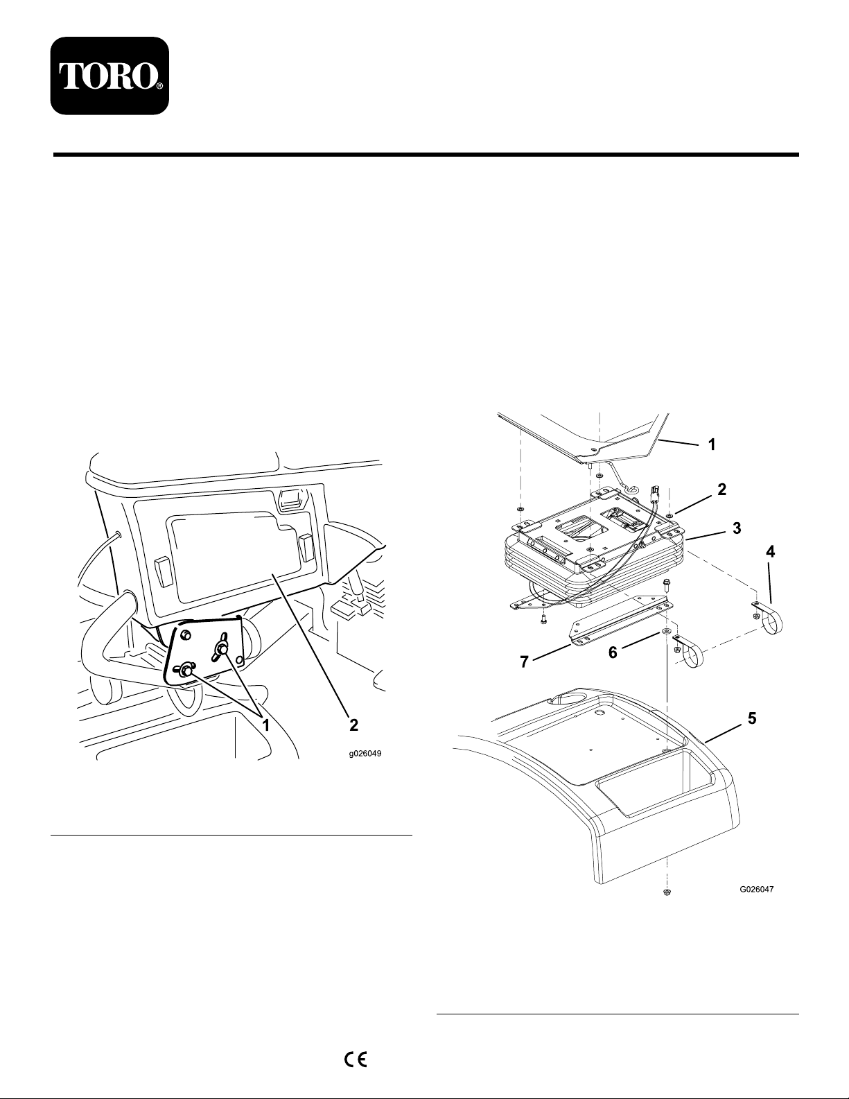
Figure1
1.Controlarmadjustingbolts
(2)
2.Controlarmaccesspanel
5.Removethe(4)nutssecuringtheseatadjustersandthe
manualtubeclampstotheseatsuspension(Figure2).
Also,removethe(4)washersbetweentheseatadjusters
andseatsuspension.Carefullysettheseatassembly
aside.
6.Removethe(4)bolts,spacersandnutssecuringthe
lowerseatbracketstotheseatbase(Figure2).Remove
theseatsuspensionandseatbracketsfromtheseat
base.Usecautionnottomisplacethespacersduring
removal.
©2014—TheT oro®Company
8111LyndaleAvenueSouth
Bloomington,MN55420
Registeratwww.T oro.com.
Figure2
1.Seatassembly5.Seatbase
2.Washer(4)6.Spacer
3.Seatsuspension
4.ManualtubeR–clamp(2)
OriginalInstructions(EN)
PrintedintheUSA.
AllRightsReserved
7.Lowerseatbrackets
*3385-268*A
Page 2
9.Mountthelowerseatbracketstotheseatbasewiththe
(4)bolts,spacersandnutspreviouslyremoved(Figure
2).
10.Positiontheseatassemblyontotheseatsuspension.
Makesureawasherisoneachadjusterstudbefore
placingitonthesuspension(Figure2).
11.Securetheseatadjustersandthemanualtubeclamps
totheseatsuspensionwiththe(4)nutspreviously
removed(Figure2).
20.Installtheaccesspaneltothecontrolarm(Figure1).
21.Plugthetractionunitpowerharness,frombackof
controlarmintotheseatharnessconnector.
22.Slidetheseatcompletelyforwardandbackwardto
ensureproperoperationandthattheseatwiresand
connectorsarenotpinchedordonocontactany
movingparts.
23.Connectthenegativebatterycabletothebattery.
12.Reinstallthecontrolarmwiththe(2)controlarm
adjustingboltspreviouslyremoved(Figure1).Adjust
asdesired.
13.Plugtheseatswitchconnectorintothewireharnessat
therearofthecontrolarm.
14.Locatetheairrideseatsuspensionplugonthewire
harnessattherearofthecontrolarm.Removethe
plugfromtheconnectorontheharness.Plugtheseat
suspensionconnectorintothewireharnessconnector.
15.Removetheaccesspanelfromthesideofthecontrol
arm(Figure1).
Note:Viewthedecalonthebacksideoftheaccess
coverfortheoptionalairrideseatsuspensionfuse
location.Ifthereisanopenslotinthefuseblockfor
thesuspension,inserta20ampandproceedtostep20.
Operation
SeatAdjustingKnobs
AdjustingLever
Foreandaftseatadjustment(Figure4).
AirControlValve
Pushincontrolvalvetoinatesuspension.Pulloutvalveto
deatesuspension(Figure4).
WeightGuide
Indicateswhenseatisadjustedtotheweightoftheoperator
(Figure4).
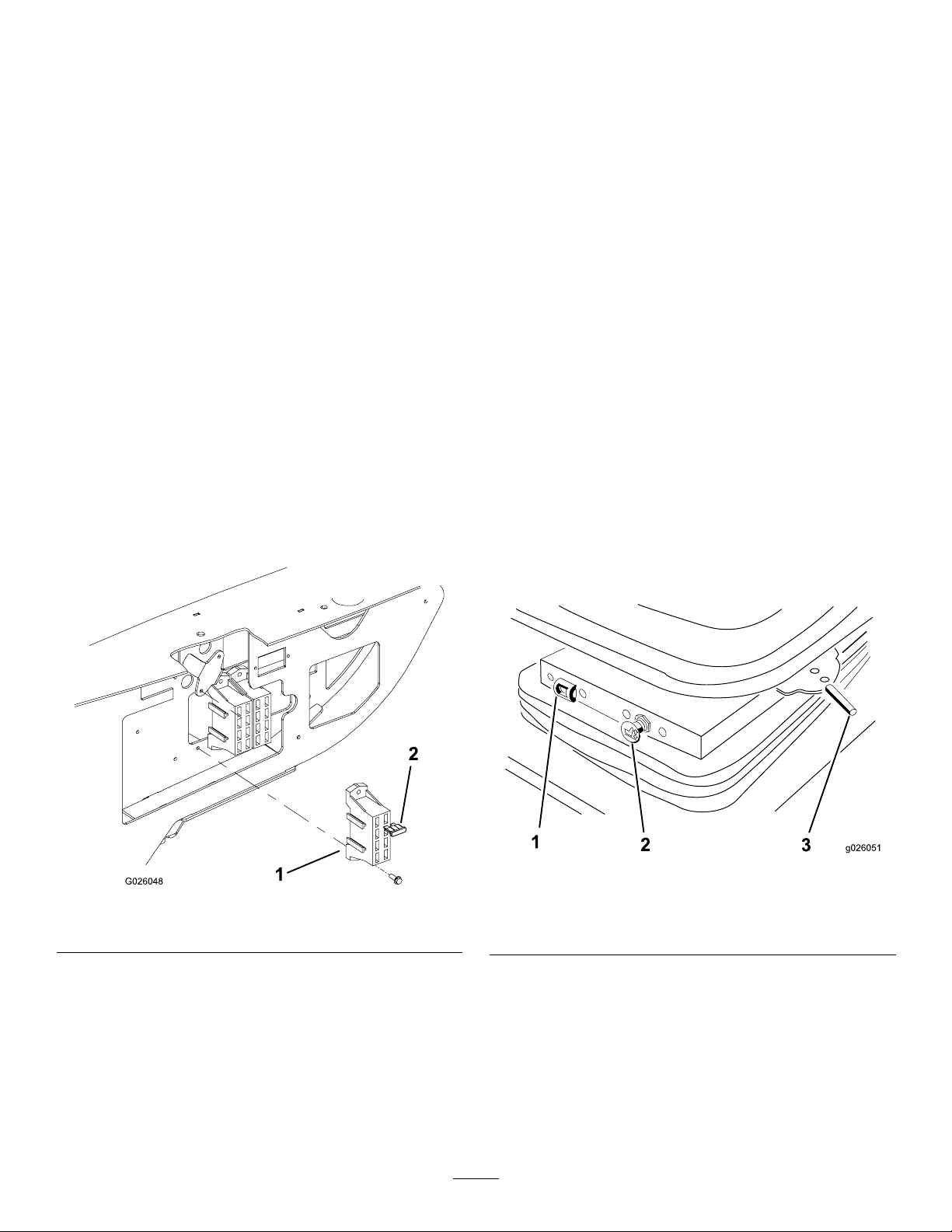
Figure3
1.Fuseblock2.Fuse20amp
16.Mountthefuseblocknexttotheexistingfuseblock
with(2)#8x1/2inchscrews(Figure3).
17.Connectthelargeredwirefromthetractionunitwire
harnesstothewireonthefuseblock.
18.Connecttheredwirewiththewhitestripelabeled“ Air
RideSeat”tooneoftheredwiresfromthefuseblock.
19.Insertthe20amp.fuseintothefuseslotwherethe
wireisconnected.
2
1.Weightguide
2.Aircontrolvalve
Figure4
3.Adjustinglever(foreand
aft)
 Loading...