

Page 1

Form No. 3354–709 Rev B
Verticutter
Reelmaster 5210/5410 Series Cutting Unit with
5in Reel
Model No. 03664—Serial No. 260000001 and Up
Operator’s Manual
English (EN)
Page 2

Contents
Introduction
Introduction 2. . . . . . . . . . . . . . . . . . . . . . . . . . . . . . . .
Introduction 2. . . . . . . . . . . . . . . . . . . . . . . . . . . . . . . .
Safety 3. . . . . . . . . . . . . . . . . . . . . . . . . . . . . . . . . . . . .
Safe Operating Practices 3. . . . . . . . . . . . . . . . . . . .
Safety and Instruction Decals 3. . . . . . . . . . . . . . . .
Setup 4. . . . . . . . . . . . . . . . . . . . . . . . . . . . . . . . . . . . .
Loose Parts 4. . . . . . . . . . . . . . . . . . . . . . . . . . . . . .
Install Transport Rollers 4. . . . . . . . . . . . . . . . . . . .
Inspection 4. . . . . . . . . . . . . . . . . . . . . . . . . . . . . . .
Adjusting the Blade Depth 5. . . . . . . . . . . . . . . . . .
Adjust the Rear Grass Shield 5. . . . . . . . . . . . . . . .
Adjusting the Roller Scrapers 5. . . . . . . . . . . . . . . .
Adjusting the Transport Rollers 6. . . . . . . . . . . . . .
Mount Verticutter Reel 6. . . . . . . . . . . . . . . . . . . . .
Operation 7. . . . . . . . . . . . . . . . . . . . . . . . . . . . . . . . . .
Training Period 7. . . . . . . . . . . . . . . . . . . . . . . . . . .
Operating Tips 7. . . . . . . . . . . . . . . . . . . . . . . . . . .
Maintenance 8. . . . . . . . . . . . . . . . . . . . . . . . . . . . . . . .
Lubrication 8. . . . . . . . . . . . . . . . . . . . . . . . . . . . . .
Adjusting the Reel Bearings 8. . . . . . . . . . . . . . . . .
Removing the Verticutter Blades from the Shaft 9.
Install Verticutter Blades 9. . . . . . . . . . . . . . . . . . .
The Toro General Commercial Products Warranty 12. .
Page
Read this manual carefully to learn how to operate and
maintain your product properly. The information in this
manual can help you and others avoid injury and product
damage. Although Toro designs and produces safe
products, you are responsible for operating the product
properly and safely.
Whenever you need service, genuine Toro parts, or
additional information, contact an Authorized Service
Dealer or Toro Customer Service and have the model and
serial numbers of your product ready. The model and serial
numbers are located on the side plate.
Write the product model and serial numbers in the space
below:
Model No.
Serial No.
This manual identifies potential hazards and has special
safety messages that help you and others avoid personal
injury and even death. Danger, Warning, and Caution are
signal words used to identify the level of hazard. However,
regardless of the hazard, be extremely careful.
Danger signals an extreme hazard that will cause serious
injury or death if you do not follow the recommended
precautions.
Warning signals a hazard that may cause serious injury or
death if you do not follow the recommended precautions.
Caution signals a hazard that may cause minor or moderate
injury if you do not follow the recommended precautions.
This manual uses two other words to highlight information.
Important calls attention to special mechanical
information and Note: emphasizes general information
worthy of special attention.
W 2006 by The Toro Company
8111 Lyndale Avenue South
Bloomington, MN 55420-1196
All Rights Reserved
Printed in the USA
2
Page 3
Safety
Safe Operating Practices
• Read, understand, and follow all instructions in the
traction unit operator’s manual before operating the
verticutters.
• Read, understand, and follow all instructions in this
operator’s manual before operating verticutters.
• Never allow children to operate the verticutters. Do not
allow adults to operate traction unit or verticutters
without proper instruction. Only trained operators who
have read this manual should operate the verticutters.
• Never operate the verticutters when under the influence
of drugs or alcohol.
• Keep all shields and safety devices in place. If a shield,
safety device or decal is illegible or damaged, repair or
replace it before operation is commenced. Also tighten
any loose nuts, bolts, and screws to ensure the
verticutters are in safe operating condition.
• Always wear substantial shoes. Do not operate
verticutters while wearing sandals, tennis shoes,
sneakers or shorts. Also, do not wear loose fitting
clothing which could get caught in moving parts.
Always wear long pants and substantial shoes. Wearing
safety glasses, safety shoes and a helmet is advisable
and required by some local ordinances and insurance
regulations.
• Remove all debris or other objects that might be picked
up and thrown by the verticutter reel blades. Keep all
bystanders away from the working area.
• If the verticutter blades strike a solid object or the unit
vibrates abnormally, stop and shut the engine off. Check
the verticutters for damaged parts. Repair any damage
before restarting and operating the verticutters.
• Lower the verticutters to the ground and remove key
from ignition switch whenever machine is left
unattended.
• Be sure verticutters are in safe operating condition by
keeping nuts, bolts and screws tight.
• Remove key from ignition switch to prevent accidental
starting of the engine when servicing, adjusting or
storing the machine.
• Perform only those maintenance instructions described
in this manual. If major repairs are ever needed or
assistance is desired, contact an Authorized Toro
Distributor.
• To ensure optimum performance and safety, always
purchase genuine Toro replacement parts and
accessories to keep the Toro all TORO. Never use
“will-fit” replacement parts and accessories made by
other manufacturers. Look for the Toro logo to assure
genuineness. Using unapproved replacement parts and
accessories could void the warranty of The Toro
Company.
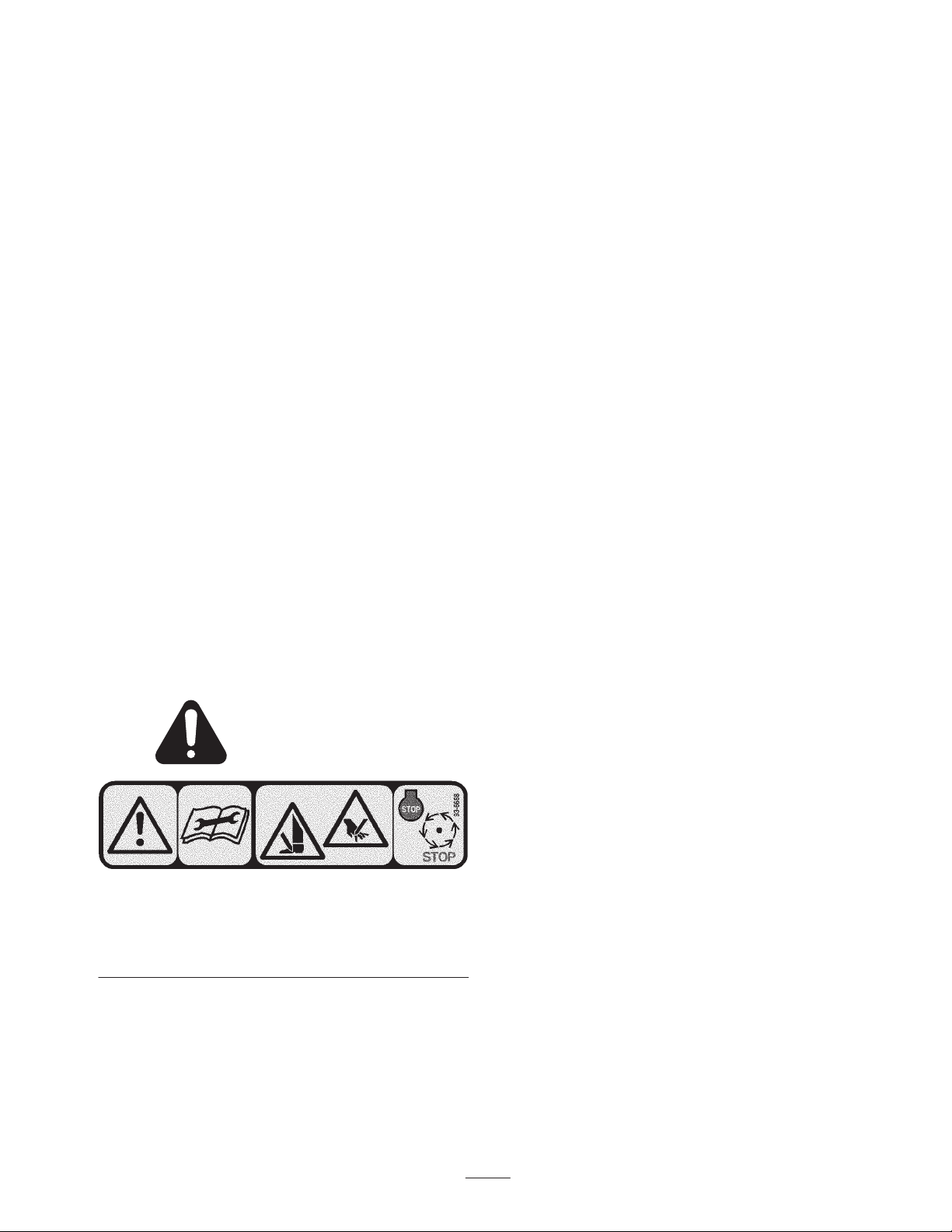
Safety and Instruction Decals
Safety decals and instructions are easily visible to the operator and are located near any area
of potential danger. Replace any decal that is damaged or lost.
93-6688
1. Warning—read the
instructions before
servicing or performing
maintenance
2. Cutting hazard of hand or
foot—stop the engine and
wait for moving parts to
stop.
3
Page 4
Setup
Loose Parts
Note: Use this chart as a checklist to ensure that all parts have been received. Without these parts, total setup cannot be
completed.
Description
Transport roller assembly 2
Cotter pin 2 Use to secure transport rollers
O–ring 1 For use with reel motor bearing housing
Operator’s manual 1 Read before operating.
Parts catalog 1
Note: Determine the left and right sides of the machine
from the normal operating position.
Whenever the cutting unit has to be tipped to expose the
verticutter blades, use the cutting unit kick stand (supplied
with traction unit) (Fig. 1).
Qty. Use
Use when the verticutters are lowered to the shop
floor
Install Transport Rollers
Secure a transport roller bracket to each sideplate pin with a
cotter pin (Fig. 2). The roller should be positined to the rear
of the vertricutter.
1. Cutting unit kick stand
Figure 1
2
1
Figure 2
1
1. Transport roller assembly 2. Cotter pin
Inspection
After the cutting unit is unboxed, inspect the following:
1. Check each end of the reel for grease. Grease should be
visibly evident in the reel bearings and internal splines
of the reel shaft.
2. Ensure that all nuts and bolts are securely tightened.
3. Make sure the carrier frame suspension operates freely
and does not bind when moved back and forth.
4
Page 5

Adjusting the Blade Depth
Note: The maximum recommended setting is 1/8 in.
(3 mm) deep blade penetration.
1. Place the verticutter reel on a level surface.
2. Place 2 gauge bars, which have the desired depth of
blade penetration below the ground, under the front and
rear rollers of the verticutter reel (on each end of the
reel) (Fig. 3).
Note: The verticutter blades must not touch the gauge bars.
3. Turn the adjusting bolt on each height-of-cut bracket
(Fig. 3) so that the reel blades come in contact with the
level surface on both ends.
2
2
1
Figure 3
1. Gauge bar (1/8”) 2. Adjusting bolt
Note: As the verticutter blades wear, the diameter of the
reel will decrease and the depth setting will change.
Check height setting periodically to insure desired
setting is achieved.
Adjust the Rear Grass Shield
1
2
Figure 4
1. Rear grass shield 2. Pivot capscrew
Caution
Do not open rear shield so it is higher than level to
ground
Thrown debris could cause personal injury
Adjusting the Roller Scrapers
1. Loosen flange nuts securing roller scrapers (Fig. 5).
2. Move scraper rods in or out to attain 0.0 to 0.03 in.
(.0 to .75mm) clearance between the scraper and roller.
3. Ensure that the scraper rod is parallel to the roller and
the level surface.
4. Tighten flange nuts to lock adjustment.
Note: When operating in turf conditions where much
debris is encountered, or unusually heavy thatch, open
the rear discharge shield to help allow the debris to
discharge from the reel.
1. Loosen the capscrews on the pivot of the grass shield
(Fig. 4).
2. Rotate the grass shield to the desired setting and tighten
the capscrews (Fig. 4).
5
Page 6

4
2
3
1
Figure 5
1. Front roller scraper
2. Rear roller scraper
3. Transport roller
4. Cotter pin
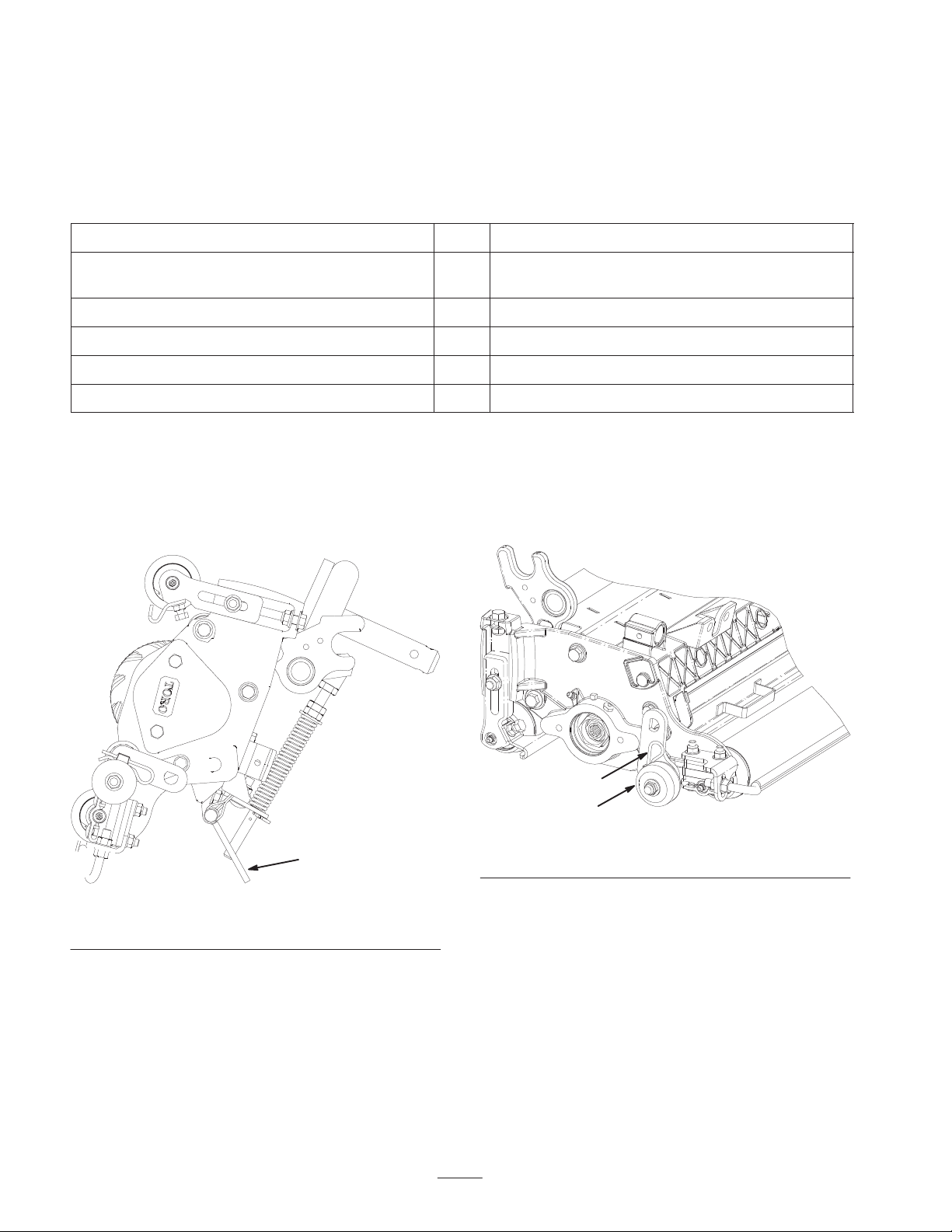
Adjusting the Transport Rollers
Before the verticutters are lowered to the shop floor or
removed from the traction unit, lower the transport rollers
(Fig. 5) to protect the blades from hard surface contact.
Motor Weight
Weight Motor Weight Motor
#1#4 #5
Motor Weight
Weight Motor
#3#2
Figure 6
Note: Counterweights are shipped installed to the right end
of the verticutters. The capscrews on the left end are to be
used for securing the hydraulic motor.
Verticutter reels are mounted to traction unit the same way
cutting units are. Refer to Traction Unit Operator’s Manual
for mounting instructions.
Important When connecting the lift arm chain to the
veticutter, use the third link from the top instead of the
forth.
1. Remove the cotter pin securing the transport roller
bracket to the sideplate pin.
2. Position the transport roller as follows:
• Lower the roller bracket before the verticutter is
lowered to the shop floor.
• Raise the roller bracket after the verticutter is raised
to the operating position.
3. Secure the transport roller bracket to the sideplate pin
with the cotter pin.
4. Repeat the procedure on the opposite end of verticutter.
Mount Verticutter Reel
Important When lowering verticutter reels, care
must be taken to prevent damage to the reel blades due
to contact with a concrete floor or a paved surface.
Lower the transport rollers before lowering the
verticuttiers to a concrete floor or a paved surface.
The verticutters can be installed at any of the five locations
on the traction unit. Figure 6 shows the orientation of the
hydraulic drive motor for each of the locations. For any of
the locations requiring the motor to be mounted on the right
end of the verticutters, install a counterweight on the left
end of the verticutters. For the locations requiring the motor
to be mounted on the left end, install a counterweight on
the right end of the verticutters.
1
Figure 7
1. Lift arm chain third link
6
Page 7

Operation
3. Power requirements to operate the verticutter reels will
vary with turf and soil conditions. Travel speed may
need to be reduced in some conditions.
Training Period
Before operating the verticutter reels, evaluate the
performance of the reel at the desired setting. Operate in a
clear, unused area to determine if the desired results will be
achieved. Adjust as desired.
Operating Tips
1. Operate the traction unit at full throttle, full reel speed
(setting 11) and between 3–5 MPH (5–8 Km/h).
2. The maximum recommended setting is 1/8 in. (3 mm)
deep blade penetration.
4. When operating in turf conditions where much debris is
encountered, or unusually heavy thatch, open the front
and rear discharge shields to help allow the debris to
discharge from the reel.
Caution
Do not open rear shield so it is higher than level to
ground
Thrown debris could cause personal injury
7
Page 8

Maintenance
Note: Determine the left and right sides of the machine
from the normal operating position.
Lubrication
Each cutting unit has (7) grease fittings (Fig. 8) that must
be lubricated regularly with No. 2 General Purpose Lithium
Base Grease.
The lubrication points are front roller (2), rear roller (2),
reel bearing (2) and bedknife adjuster.
Important Lubricating cutting units immediately after
washing helps purge water out of bearings and increases
bearing life.
1. Wipe each grease fitting with a clean rag.
2. Apply grease until clean grease is seen coming out of
roller seals and bearing relief valve.
3. Wipe excess grease away.
1
Figure 9
1. Reel shaft
2. If end play exists, proceeded as follows:
A. Loosen external set screw securing bearing
adjusting nut to bearing housing located on the left
side of the cutting unit (Fig. 10).
1
Figure 8
1. Relief valve
Adjusting the Reel Bearings
To insure long life of the reel bearings, periodically check if
reel end play exits. The reel bearings can be checked and
adjusted as follows:
1. Hold on to the reel shaft and try to move the reel
assembly side to side (Fig. 9).
1
1. Set screw 2. Bearing adjusting nut
B. Using a 1–3/8” socket wrench, slowly tighten the
reel bearing adjustment nut until no end play of the
reel exists. If adjusting nut does not eliminate reel
end play, replace reel bearings.
2
Figure 10
Note: Reel bearings do not require pre–load. Over
tightening reel bearing adjuster nut will
damage reel bearings.
3. Retighten set screw securing bearing adjusting nut to
bearing housing. Torque set screw to 12–15 in–lbs.
8
Page 9

Removing the Verticutter
Install Verticutter Blades
Blades from the Shaft
1. Secure the end of the verticutter shaft, which has only
one washer and nut, in a vise.
2. On other end of shaft, rotate nut counter–clockwise.
Remove nut.
Caution
The blades are extremely sharp and may have
burrs that will cut your hands.
Use caution when removing the blades from the
shaft.
3. Remove small spacer, washer, blades and large spacers.
Clean and lubricate hex shaft with a light coating of
grease to simplify assembly.
Important Do not invert verticutter reel blades. The
order of disassembly is extremely important. Do not
invert verticutter reel blades when disassembling or
reverse the order when assembling. Note the verticutter
blades index hole. The index hole is provided for
assembly in order to obtain the proper helix for the
verticutter reel.
1. First, assemble a reel blade (Fig. 11).
2. Next, assemble a large spacer.
3. Do not invert reel blades when reassembling on reel
shaft. If the blades are inverted, the blades that are in
use, (rounded) will be mixed with the sharp ends of the
blades which were not in use. This will cause
unsatisfactory performance in the verticutter reel unit.
Attention should always be taken when disassembling
verticutter blades from reel.
4. Install the next blade clockwise
hole (Fig. 12) is not aligned with the first blade hole by
one flat of the shaft. Continue to install spacers and
blades in this manner until the full complement of
blades have been installed. When properly assembled,
the blades will be staggered in such a manner to give a
helix appearance.
so the index reference
1. Shaft
2. Nut
3. Washer
This end in vise
6
5
4
3
Figure 11
4. Small spacer
5. Blade (16)
6. Large spacer (15)
1
1
Figure 12
1. Index reference hole
5. Install small spacer to shaft.
6. Apply Blue Loctite #242 to nut. Install nut onto shaft,
(machined side of nut toward spacer) and tighten to
80 –100 ft–lb.
2
9
Page 10

10
Page 11

Page 12

The Toro General Commercial Products Warranty
A Two-Year Limited Warranty
Conditions and Products Covered
The Toro Company and its affiliate, Toro Warranty Company,
pursuant to an agreement between them, jointly warrant your Toro
Commercial Product (“Product”) to be free from defects in
materials or workmanship for two years or 1500 operational
hours*, whichever occurs first. Where a warrantable condition
exists, we will repair the Product at no cost to you including
diagnosis, labor, parts, and transportation. This warranty begins
on the date the Product is delivered to the original retail purchaser.
* Product equipped with hour meter
Instructions for Obtaining Warranty Service
You are responsible for notifying the Commercial Products
Distributor or Authorized Commercial Products Dealer from whom
you purchased the Product as soon as you believe a warrantable
condition exists.
If you need help locating a Commercial Products Distributor or
Authorized Dealer, or if you have questions regarding your
warranty rights or responsibilities, you may contact us at:
Toro Commercial Products Service Department
Toro Warranty Company
8111 Lyndale Avenue South
Bloomington, MN 55420-1196
952-888-8801 or 800-982-2740
E-mail: commercial.service@toro.com
Owner Responsibilities
As the Product owner, you are responsible for required maintenance and adjustments stated in your operator’s manual. Failure
to perform required maintenance and adjustments can be grounds
for disallowing a warranty claim.
Items and Conditions Not Covered
Not all product failures or malfunctions that occur during the
warranty period are defects in materials or workmanship. This
express warranty does not cover the following:
• Product failures which result from the use of non-Toro
replacement parts, or from installation and use of add-on,
modified, or unapproved accessories
• Product failures which result from failure to perform required
maintenance and/or adjustments
• Product failures which result from operating the Product in an
abusive, negligent or reckless manner
• Parts subject to consumption through use unless found to be
defective. Examples of parts which are consumed, or used up,
during normal Product operation include, but are not limited to,
blades, reels, bedknives, tines, spark plugs, castor wheels,
tires, filters, belts, and certain sprayer components such as
diaphragms, nozzles, and check valves, etc.
• Failures caused by outside influence. Items considered to be
outside influence include, but are not limited to, weather,
storage practices, contamination, use of unapproved coolants,
lubricants, additives, or chemicals, etc.
• Normal “wear and tear” items. Normal “wear and tear” includes,
but is not limited to, damage to seats due to wear or abrasion,
worn painted surfaces, scratched decals or windows, etc.
Parts
Parts scheduled for replacement as required maintenance are
warranted for the period of time up to the scheduled replacement
time for that part.
Parts replaced under this warranty become the property of Toro.
Toro will make the final decision whether to repair any existing part
or assembly or replace it. Toro may use factory remanufactured
parts rather than new parts for some warranty repairs.
General Conditions
Repair by an Authorized Toro Distributor or Dealer is your sole
remedy under this warranty.
Neither The Toro Company nor Toro Warranty Company is
liable for indirect, incidental or consequential damages in
connection with the use of the Toro Products covered by this
warranty, including any cost or expense of providing substitute equipment or service during reasonable periods of
malfunction or non-use pending completion of repairs under
this warranty. Except for the Emissions warranty referenced
below, if applicable, there is no other express warranty. All
implied warranties of merchantability and fitness for use are
limited to the duration of this express warranty.
Some states do not allow exclusions of incidental or consequential
damages, or limitations on how long an implied warranty lasts, so
the above exclusions and limitations may not apply to you.
This warranty gives you specific legal rights, and you may also
have other rights which vary from state to state.
Note regarding engine warranty: The Emissions Control System
on your Product may be covered by a separate warranty meeting
requirements established by the U.S. Environmental Protection
Agency (EPA) and/or the California Air Resources Board (CARB).
The hour limitations set forth above do not apply to the Emissions
Control System Warranty. Refer to the Engine Emission Control
Warranty Statement printed in your operator’s manual or contained in the engine manufacturer’s documentation for details.
Countries Other than the United States or Canada
Customers who have purchased Toro products exported from the United States or Canada should contact their Toro Distributor (Dealer)
to obtain guarantee policies for your country, province, or state. If for any reason you are dissatisfied with your Distributor’s service or
have difficulty obtaining guarantee information, contact the Toro importer. If all other remedies fail, you may contact us at Toro Warranty
Company.
Part No. 374-0031 Rev. C
 Loading...