

Toro 03634, 03635, reelmaster 5210 series, reelmaster 5410 series, reelmaster 5010-h series Operator's Manual
Page 1
FormNo.3392-633RevA
8and11-BladeDPACuttingUnit
with5inReel
Reelmaster
®
5010-H/5210/5410Series
TractionUnit
ModelNo.03634—SerialNo.315000001andUp
ModelNo.03635—SerialNo.315000001andUp
Registeratwww.T oro.com.
OriginalInstructions(EN)
*3392-633*A
Page 2
WARNING
CALIFORNIA
Proposition65Warning
Thisproductcontainsachemicalorchemicals
knowntotheStateofCaliforniatocausecancer,
birthdefects,orreproductiveharm.
ThisproductcomplieswithallrelevantEuropeandirectives.
Fordetails,pleaseseetheDeclarationofIncorporation(DOI)
atthebackofthispublication.
ModelNo.
SerialNo.
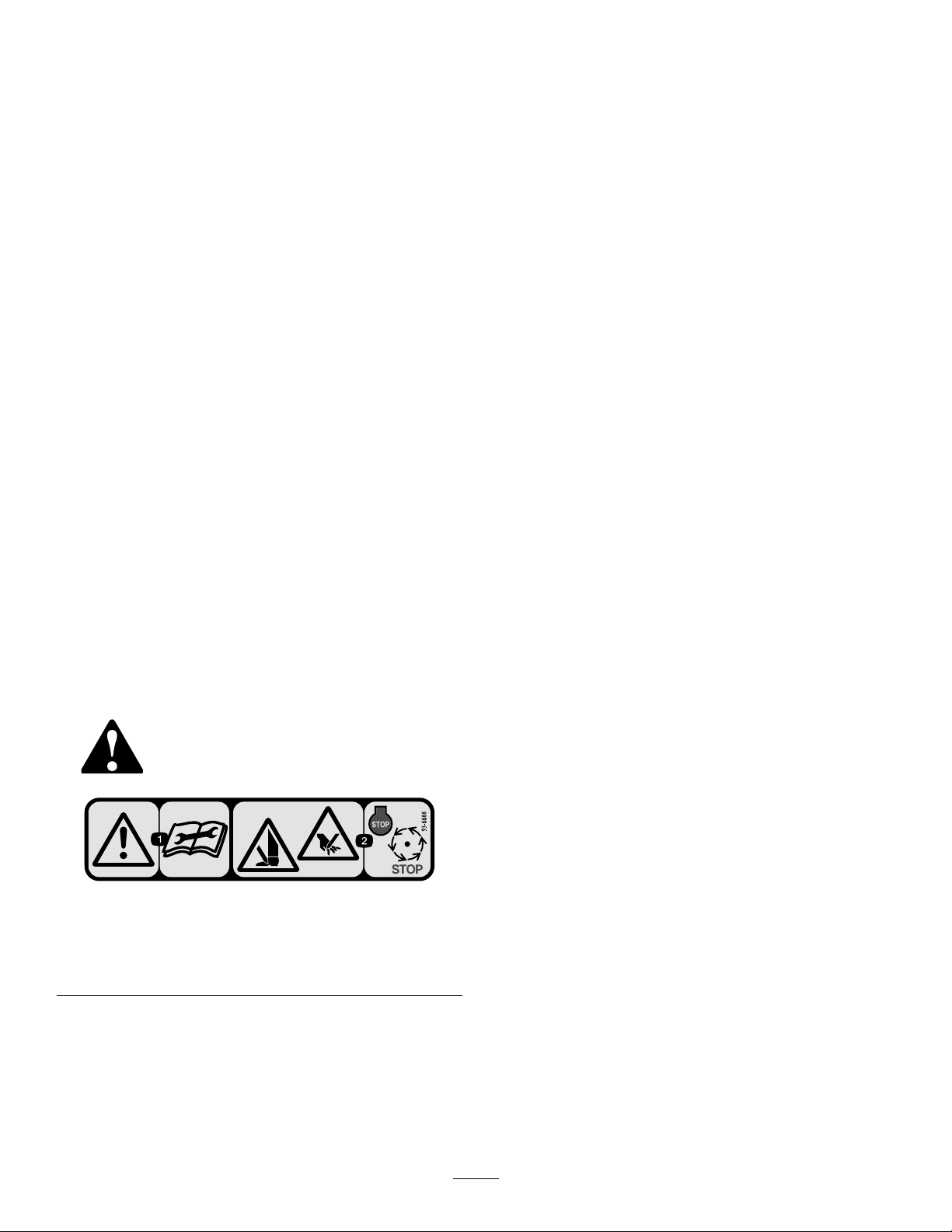
Thismanualidentiespotentialhazardsandhassafety
messagesidentiedbythesafetyalertsymbol(Figure2),
whichsignalsahazardthatmaycauseseriousinjuryordeath
ifyoudonotfollowtherecommendedprecautions.
Thisreel-bladelawnmowerismountedtoaride-onmachine
andisintendedtobeusedbyprofessional,hiredoperatorsin
commercialapplications.Itisprimarilydesignedforcutting
grassonwell-maintainedlawnsinparks,golfcourses,sports
elds,andoncommercialgrounds.Itisnotdesignedfor
cuttingbrush,mowinggrassandothergrowthalongside
highways,orforagriculturaluses.
Introduction
Readthisinformationcarefullytolearnhowtooperateand
maintainyourproductproperlyandtoavoidinjuryand
productdamage.Youareresponsibleforoperatingthe
productproperlyandsafely.
YoumaycontactTorodirectlyatwww .Toro.comforproduct
safetyandoperationtrainingmaterials,accessoryinformation,
helpndingadealer,ortoregisteryourproduct.
Wheneveryouneedservice,genuineT oroparts,oradditional
information,contactanAuthorizedServiceDealerorToro
CustomerServiceandhavethemodelandserialnumbersof
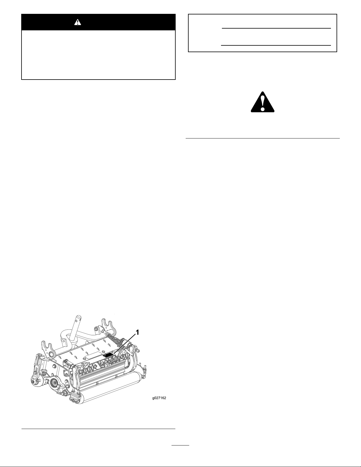
yourproductready.Figure1identiesthelocationofthe
modelandserialnumbersontheproduct.Writethenumbers
inthespaceprovided.
Figure2
1.Safetyalertsymbol
Thismanualuses2wordstohighlightinformation.
Importantcallsattentiontospecialmechanicalinformation
andNoteemphasizesgeneralinformationworthyofspecial
attention.
Contents
Safety...........................................................................3
SafetyandInstructionalDecals.................................3
Setup............................................................................4
1InspectingtheCuttingUnit....................................4
2CuttingUnitKickstand..........................................4
3AdjustingtheRearShield.......................................4
4InstallingtheLooseParts.......................................5
ProductOverview..........................................................7
Specications.........................................................7
CuttingUnitAccessoriesandKits(seeparts
catalogforpartnumbers)......................................7
Operation.....................................................................8
MakingAdjustments................................................8
Height-of-CutChartTerms.....................................10
Height-of-CutChart...............................................11
ServicingtheBedknife............................................15
Maintenance.................................................................16
Lubrication............................................................16
ServicingtheBedbar...............................................16
ServicingtheRoller.................................................18
1.Locationofthemodelandserialnumbers
©2015—TheToro®Company
8111LyndaleAvenueSouth
Bloomington,MN55420
Figure1
Contactusatwww.Toro.com.
2
PrintedintheUSA
AllRightsReserved
Page 3
Safety
ThismachinehasbeendesignedinaccordancewithENISO
5395:2013.
Hazardcontrolandaccidentpreventionaredependent
upontheawareness,concern,andpropertraining
ofthepersonnelinvolvedintheoperation,transport,
maintenance,andstorageofthemachine.Improper
useormaintenanceofthemachinecanresultininjury
ordeath.Toreducethepotentialforinjuryordeath,
complywiththefollowingsafetyinstructions.
•Read,understand,andfollowallinstructionsinthe
tractionunitoperatorsmanualbeforeoperatingthe
cuttingunit.
•Read,understand,andfollowallinstructionsinthis
Operator’sManualbeforeoperatingthecuttingunit.
•Neverallowchildrentooperatethetractionunitor
cuttingunits.Donotallowadultstooperatetractionunit
orcuttingunitswithoutproperinstruction.Onlytrained
operatorswhohavereadthismanualshouldoperatethe
cuttingunits.
•Neveroperatethecuttingunitswhenundertheinuence
ofdrugsoralcohol.
•Keepallshieldsandsafetydevicesinplace.Ifashield,
safetydeviceordecalisillegibleordamaged,repairor
replaceitbeforeoperationiscommenced.Alsotighten
anyloosenuts,bolts,andscrewstoensurecuttingunitis
insafeoperatingcondition.
•Alwayswearsubstantialshoes.Donotoperatecutting
unitswhilewearingsandals,tennisshoes,sneakersor
shorts.Also,donotwearloosettingclothingwhich
couldgetcaughtinmovingparts.Alwayswearlongpants
andsubstantialshoes.Wearingsafetyglasses,safetyshoes
andahelmetisadvisableandrequiredbysomelocal
ordinancesandinsuranceregulations.
•Removealldebrisorotherobjectsthatmightbepicked
upandthrownbythecuttingunitreelblades.Keepall
bystandersawayfromtheworkingarea.
•Ifthecuttingbladesstrikeasolidobjectortheunit
vibratesabnormally,stopandshuttheengineoff.Check
cuttingunitfordamagedparts.Repairanydamagebefore
restartingandoperatingthecuttingunit.
•Lowerthecuttingunitstothegroundandremovekey
fromignitionswitchwhenevermachineisleftunattended.
•Besurecuttingunitsareinsafeoperatingconditionby
keepingnuts,boltsandscrewstight.
•Removekeyfromignitionswitchtopreventaccidental
startingoftheenginewhenservicing,adjustingorstoring
themachine.
•Performonlythosemaintenanceinstructionsdescribedin
thismanual.Ifmajorrepairsareeverneededorassistance
isdesired,contactanAuthorizedT oroDistributor.
•Toensureoptimumperformanceandsafety ,always
purchasegenuineTororeplacementpartsandaccessories.
Donotuse"will-t"replacementpartsand
accessoriesmadebyothermanufacturers.Lookfor
theT orologotoassuregenuineness.Usingunapproved
replacementpartsandaccessoriescouldvoidthewarranty
ofTheToroCompany.
SafetyandInstructionalDecals
Safetydecalsandinstructionsareeasilyvisibletotheoperatorandarelocatednearanyareaofpotential
danger.Replaceanydecalthatisdamagedorlost.
93–6688
1.Warning—readthe
Operator’sManualbefore
performingmaintenance.
2.Cuttinghazardofhandor
foot—stoptheengineand
waitforallmovingpartsto
stop.
3
Page 4
Setup
LooseParts
Usethechartbelowtoverifythatallpartshavebeenshipped.
ProcedureDescription
1
2
3
4
Cuttingunit
Nopartsrequired
Nopartsrequired
Straightgreasetting
O-ring
MediaandAdditionalParts
Description
PartsCatalog
Operator'sManual
Note:Determinetheleftandrightsidesofthemachine
fromthenormaloperatingposition.
1
InspectingtheCuttingUnit
Qty.
Qty.
1Inspectthecuttingunit.
–
–
1
1
1
1
Reviewthematerialandsaveinanappropriateplace:
Usethekickstandwhentippingthe
cuttingunit.
Adjusttherearshield.
Installthelooseparts.
Use
Use
2
CuttingUnitKickstand
NoPartsRequired
Partsneededforthisprocedure:
1
Cuttingunit
Procedure
Afterthecuttingunitisremovedfromthebox,inspectthe
following:
1.Checkeachendofthereelforgrease.
Note:Greaseshouldbevisiblyevidentintheinternal
splinesofthereelshaft.
2.Ensurethatallnutsandboltsaresecurelytightened.
3.Makesurethatthecarrierframesuspensionoperates
freelyanddoesnotbindwhenmovedbackandforth.
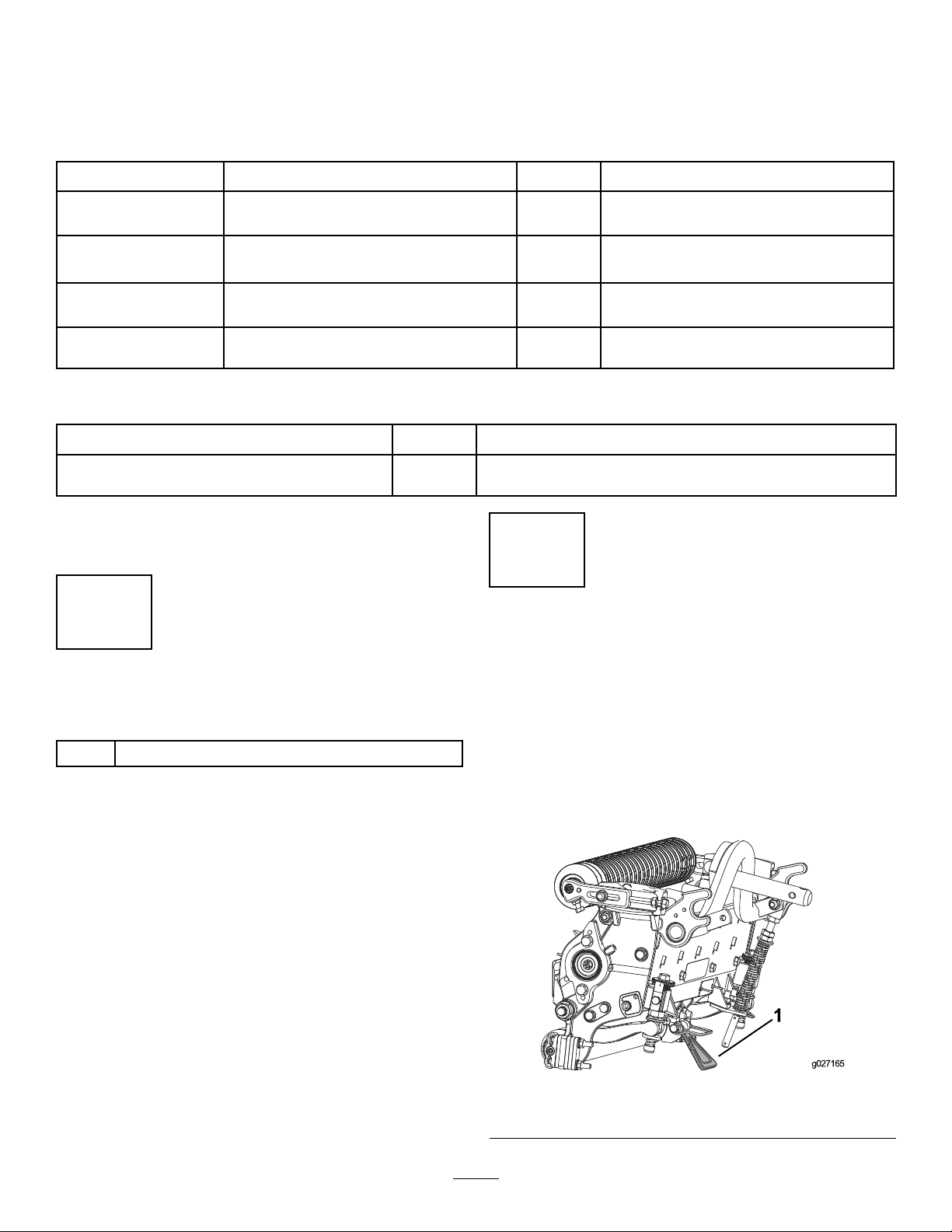
Procedure
Wheneverthecuttingunithastobetippedtoexposethe
bedknife/reel,propuptherearofthecuttingunitwiththe
kickstand(suppliedwiththetractionunit)tomakesurethat
thenutsonthebackendofthebedbaradjustingscrewsare
notrestingontheworksurface(Figure3).
Figure3
1.Cuttingunitkickstand
4
Page 5
3
4
AdjustingtheRearShield
NoPartsRequired
Procedure
Undermostconditions,bestdispersionisattainedwhenthe
rearshieldisclosed(frontdischarge).Whenconditionsare
heavyorwet,rearshieldmaybeopened.
Toopentherearshield(Figure4),loosenthecapscrew
securingtheshieldtotheleftsideplate,rotatetheshieldto
theopenpositionandtightenthecapscrew.
InstallingtheLooseParts
Partsneededforthisprocedure:
1
Straightgreasetting
1
O-ring
Procedure
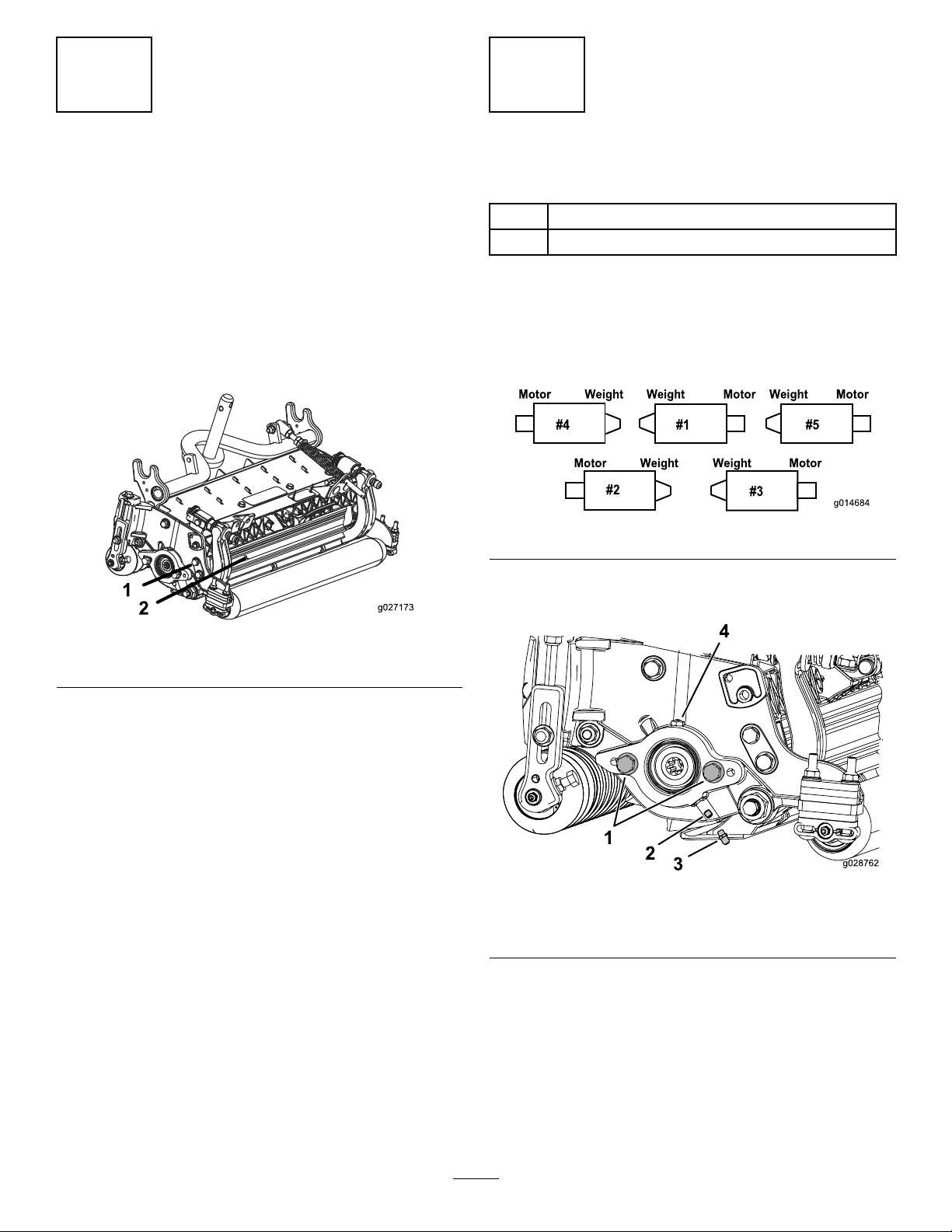
Thegreasettingsmustbeinstalledonthereelmotorsideof
thecuttingunit.Usethefollowingdiagramtodeterminethe
positionofthereelmotors.
Figure5
1.Removeanddiscardthesetscrewonthereel-motor
side-plate(Figure6).
1.Capscrew
Figure4
2.Rearshield
Figure6
1.Capscrew(2)3.Greasetting
2.Setscrew4.Greasevent
2.Installthestraightgreasetting(Figure6).
3.Iftherearenocapscrewsonthereel-motorside-plate,
installthem(Figure6).
4.InstalltheO-ringonthereelmotor(Figure7).
5
Page 6

Figure7
1.O-ring
5.Installthereelmotor,andgreasethesideplateuntil
excessgreasepoursoutofthegreasevent(Figure6).
6
Page 7

ProductOverview
Specications
ModelNumberNetWeight
03634
03635
41kg(90lb)
42kg(93lb)
CuttingUnitAccessoriesandKits(see partscatalogforpartnumbers)
Note:Allaccessoriesandkitsare1percuttingunitunless
otherwisespecied.
BroomerKit:Multiplebrushstripswovenintothehelical
groomerbladesimprovetheeffectivenessofthegroomerkit.
Performanceofthegroomerisenhancedbyenablingafull
width"Brooming"effectofturfwhileopeningupthecanopy
forbettergrassclippingintegration.Thecombinationof
groomerandbroomersystemsoptimizethequalityofcutand
after-cutappearanceformoreconsistentplayingconditions.
CollarKit(6neededperroller):Reducesover-lapmarks
forwarmseasongrasses(Bermuda,Zoysia,Paspalum).This
kitisinstalledontheouter3groovesoftheexistingWiehle
roller,butisnotasaggressiveastheShoulderroller.
Comb/ScraperKit:Axedcombinstalledbehindthefront
rollerwhichhelpsreducegrainandspongyturfbystanding
upthegrassbeforecutting.AscraperforthefrontWiehle
rollerisincludedinthekit.
FullFrontRoller:Producesamorepronouncedstriping
(repeatedcuttinginthesamedirection/path).Effective
height-of-cutisraisedandthequalityofthecutisreduced.
GrassBasketKit:Aseriesofclippingcollectionbaskets
attachedtothefrontofthecuttingunitstocollectgrass
clippings.
GroomerKit:Rotatingbladesassembledbehindthefront
rollerwhichprovidethebestmethodforreducinggrainand
spongyturfbystandingupthegrassbeforecutting.The
groomeralsoknocksoffanydewfordecreasedstickiness
andclumping.Thiskitopensupthecanopyforbettergrass
clippingintegration,andliftsgrassforacleancrispcut.The
overalldesignimprovesthequalityofcutforhealthierturf
grasswhileimprovingtheaftercutappearance.
HighHOCKit:Newfrontrollerbracketsandadditional
spacersfortherearrollerallowsthecuttingunittoachieve
heightsofcutabove5mm(1.00inch).Thenewfrontroller
bracketsalsomovesthefrontrolleroutfarthertoimprove
after-cutappearanceattheseheightsofcut.
LongRearRoller:Helpsreduceover-lapmarksand
mismatchbetweencuttingunitsforwarmseasongrasses
(Bermuda,Zoysia,Paspalum).
RearLiftCylinderKit:Collarsassembledontherearcutting
unitliftarmcylinderstolimittheheightofthecuttingunits.
Thisincreasestheareaforthereargrassbaskets.
RearRollerBrushKit:Ahigh-speed,high-contactbrush
thatkeepstherearrollerfreeofgrassanddebris,which
maintainsaconsistentheightofcutandpreventsclumping.
Thisleadstoabetterafter-cutappearance.
RollerRebuildKit:Includesallthebearings,bearingnuts,
innerseals,andoutersealsrequiredtorebuildaroller.
RollerRebuildT oolKit:Includesallthetoolsand
installationinstructionsrequiredtorebuildarollerwiththe
rollerrebuildkit.
Scrapers(Wiehle,Shoulder,Rearroller,FullFront
Roller):Fixedscrapersforalloptionalrollersareavailable
forreducinggrassbuilduponrollerswhichcanaffect
height-of-cutsettings.
ShoulderRoller:Helpsreduceover-lapmarksforwarm
seasongrasses(Bermuda,Zoysia,Paspalum).
WeightKit:Includescounterweightsthatattachtothe
cuttingunitsandmaintainbalancewhenotheraccessories
arenotinuse.
7
Page 8
Operation
Note:Determinetheleftandrightsidesofthemachine
fromthenormaloperatingposition.
MakingAdjustments
AdjustingtheBedknifetotheReel
Usethisproceduretosetthebedknifetothereelandtocheck
theconditionofthereelandbedknifeandtheirinteraction.
Aftercompletingthisprocedure,alwaystestthecutting
unitperformanceunderyoureldconditions.Youmay
needtomakefurtheradjustmentstoobtainoptimalcutting
performance.
Important:Donotovertightenthebedknifetothereel
oryouwilldamageit.
•Afterbacklappingthecuttingunitorgrindingthereel,you
mayneedtomowwiththecuttingunitforafewminutes
andthenperformthisproceduretoadjustthebedknifeto
thereelasthereelandbedknifeadjusttoeachother.
•Youmayneedadditionaladjustmentsiftheturfis
extremelydenseoryourcuttingheightisverylow .
Youwillneedthefollowingtoolstocompletethisprocedure:
•Shim(0.002inch)
Figure9
1.Cuttingunitkickstand
4.Rotatethereelsothatabladecrossesthebedknife
approximately25mm(1inch)infromtheendofthe
bedknifeontherighthandsideofthecuttingunit.
Note:Putanidentifyingmarkonthisbladetomake
subsequentadjustmentseasier.
5.Insertthe0.05mm(0.002inch)shimbetweenthe
markedreelbladeandthebedknifeatthepointwhere
thebladecrossesthebedknife.
6.Turntherightbedbaradjusterclockwiseuntilyoufeel
lightpressure(i.e.drag)ontheshim,thenbackoffthe
bedbaradjustertwoclicksandremovetheshim.
•Cuttingperformancepaper
1.Positionthecuttingunitonaat,levelworksurface.
2.Turnthebedbaradjustingscrewscounterclockwiseto
ensurethatthebedbardoesnotcontactthereel(Figure
8).
Figure8
1.Bedbaradjustingscrew
3.Tipthemower,toexposethebedknifeandreel.
Important:Makesurethatthenutsontheback
endofthebedbaradjustingscrewsarenotresting
ontheworksurface(Figure9).
Note:Adjusting1sideofthecuttingunitaffectsthe
otherside,the2clickswillprovideclearanceforwhen
theothersideisadjusted.
Note:Ifstartingwithalargegap,bothsidesshould
initiallybedrawncloserbyalternatelytighteningthe
rightandlefthandsides.
7.Slowlyrotatethereelsothatthesamebladethatyou
checkedontherightsideiscrossingthebedknife
approximately25mm(1inch)infromtheendofthe
bedknifeonthelefthandsideofthecuttingunit.
8.Turntheleftbedbaradjusterclockwiseuntiltheshim
canbeslidthroughthereeltobedknifegapwithlight
drag.
9.Returntotherightsideandadjustasnecessarytoget
lightdragontheshimbetweenthesamebladeand
bedknife.
10.Repeatsteps8and9untiltheshimcanbeslidthrough
bothgapswithslightdrag,butoneclickinonboth
sidespreventstheshimfrompassingthroughonboth
sides.
Note:Thebedknifeisnowparalleltothereel.
Note:Thisprocedureshouldnotbeneededondaily
adjustments,butshouldbedoneaftergrindingor
disassembly.
8
Page 9

11.Fromthisposition(i.e.1clickinandshimnotpassing
through)turnthebedbaradjustersclockwise2clicks
each.
6.Securetherollerbracketandspacerstotheunderside
ofthesideplatemountingangeswiththenuts
previouslyremoved.
Note:Eachclickturnedmovesthebedknife0.018
mm(0.0007inches).Donotovertightenthe
adjustingscrews.
12.Testthecuttingperformancebyinsertingalongstrip
ofT orocuttingperformancepaperbetweenreeland
bedknife,perpendiculartothebedknife(Figure10).
Slowlyrotatethereelforward;itshouldcutthepaper.
Figure10
Note:Shouldexcessivereeldragbeevident,itwillbe
eithernecessarytobacklaporregrindthecuttingunit
toachievethesharpedgesneededforprecisioncutting.
7.Verifythatbedknife-to-reelcontactiscorrect.Tipthe
mowertoexposethefrontandrearrollersandthe
bedknife.
Note:Thepositionoftherearrollertothereel
iscontrolledbythemachiningtolerancesofthe
assembledcomponentsandparallelingisnotrequired.
Alimitedamountofadjustmentispossiblebysetting
thecuttingunitonasurfaceplateandlooseningthe
sideplatemountingcapscrews(Figure12).
Figure12
1.Sideplatemountingcapscrews
8.Adjustandtightencapscrewsandtorquethecap
screwsto37-45N-m(27-33ft-lb).
AdjustingtheRearRoller
1.Adjusttherearrollerbrackets(Figure11)tothedesired
heightofcutrangebypositioningtherequiredamount
ofspacersbelowthesideplatemountingange(Figure
11)pertheHOCChart.
Figure11
1.Spacer3.Sideplatemountingange
2.Rollerbracket
2.Raisetherearofthecuttingunitandplaceablock
underthebedknife.
3.Removethe2nutssecuringeachrollerbracketandthe
spacertoeachsideplatemountingange.
4.Lowertherollerandthescrewsfromsideplate
mountingangesandspacers.
5.Placethespacersontothescrewsonrollerbrackets.
9
Page 10

Height-of-CutChartTerms
Height-of-CutSetting(HOC)
Thedesiredheight-of-cut.
BenchSetHeight-of-Cut
Thebenchsetheight-of-cutistheheightatwhichthetop
edgeofthebedknifeissetaboveaatlevelsurfacethat
contactsthebottomofboththefrontandrearroller.
EffectiveHeight-of-Cut
Thisistheactualheightthatthegrasshasbeencut.Fora
givenbenchsetheight-of-cut,theactualheight-of-cutwill
varydependingonthetypeofgrass,timeofyear,turf,and
soilconditions.Thecuttingunitsetup(aggressivenessofcut,
rollers,bedknives,attachmentsinstalled,turfcompensation
settings,etc.)willalsoaffecttheeffectiveheightofcut.Check
theeffectiveheight-of-cutusingtheTurfEvaluator(model
04399)regularlytodeterminethedesiredbenchsetheight
ofcut.
RearSpacers
Thenumberofrearspacersdeterminestheaggressiveness
ofcutforthecuttingunit.Foragivenheightofcut,adding
spacers,belowthesideplatemountingange,increasesthe
aggressivenessofthecuttingunit.Allcuttingunitsona
givenmachinemustbesettothesameaggressivenessofcut
(Numberofrearspacers,partno.106-3925),otherwisethe
after-cutappearancecouldbenegativelyaffected(Figure13).
ChainLinks
Thelocationatwhichtheliftarmchainisattacheddetermines
therearrollerpitchangle(Figure14).
AggressivenessofCut
Aggressivenessofcuthasasignicantimpactonthe
performanceofthecuttingunit.AggressivenessofCutrefers
totheangleofthebedkniferelativetotheground(Figure13).
Thebestcuttingunitsetupisdependentonyourturf
conditionsanddesiredresults.Experiencewiththecutting
unitonyourturfwilldeterminethebestsettingtouse.
Aggressivenessofcutmaybeadjustedthroughoutthecutting
seasontoallowforvariousturfconditions.
Ingeneral,lesstonormalaggressivesettingsaremore
appropriateforwarmseasongrasses(Bermuda,paspalum,
zoysia)whilecoolseasongrasses(bent,bluegrass,rye)may
requirenormaltomoreaggressivesetups.Moreaggressive
setupscutmoregrassoffbyallowingthespinningreeltopull
moregrassupintothebedknife.
Figure14
1.Liftchain
2.U-backet
3.Bottomhole
Groomer
Thesearetherecommendedheight-of-cutsettingswhena
groomerkitisinstalledonthecuttingunit.
1.Rearspacers
2.Sideplatemountingange
Figure13
3.Aggressivenessofcut
10
Page 11

Height-of-CutChart
HOCSettingAggressivenessofCutNo.ofRearSpacersNo.ofChainLinksWithGroomerkits
0.64cm(0.250inches)
0.95cm(0.375inches)
1.27cm(0.500inches)
1.56cm(0.625inches)
1.91cm(0.750inches)
2.22cm(0.875inches)
2.54cm(1.000inch)
2.86cm(1.125inches)*
3.18cm(1.250inches)*
3.49cm(1.375inches)*
3.81cm(1.500inches)*
+IndicatestheU-bracket,onliftarm,ispositionedinthebottomhole(Figure14).
*HighHOCKit(PartNo.110-9600)mustbeinstalled.FrontHOCbracketmustbepositionedinthetopsideplatehole.
**YindicatesthatthiscombinationofHOCandspacerscanbeusedwithgroomers.
Less
Normal
More
Less
Normal
More
Less
Normal
More
Less
Normal
More
Less
Normal
More
Less
Normal
More
Less
Normal
More
Less
Normal
More
Less
Normal
More
Less
Normal
More
Less
Normal
More
0
0
1
0
1
2
0
1
2
1
2
3
2
3
4
2
3
4
3
4
5
4
5
6
4
5
6
4
5
6
5
6
7
3+
3+
3
4
3
3
4
3+
3
4
3
3
3+
3
3
4
3
3
3+
3
3
4
3
3
4
3
3
4
3
3
3+
3
3
installed**
Y
Y
-
Y
Y
-
Y
Y
Y
Y
Y
-
Y
Y
-
Y
Y
-
Y
Y
-
-
-
-
-
-
-
-
-
-
-
-
-
Note:Changing1chainlinkchangestherearrollerpitchanglemovementby7.0degrees.
Note:ChangingtheU-bracketontheliftarmtothebottomholeadds3.5degreestotherearrollerpitchangle.
11
Page 12

AdjustingtheHeight-of-Cut
Note:Forheightsofcutgreaterthan2.54cm(1.000inch)
theHighHeight-of-CutKitmustbeinstalled.
1.Loosenlocknutssecuringheight-of-cutbracketsto
cuttingunitsideplates(Figure15).
Figure15
1.Adjustingscrew
2.Locknut
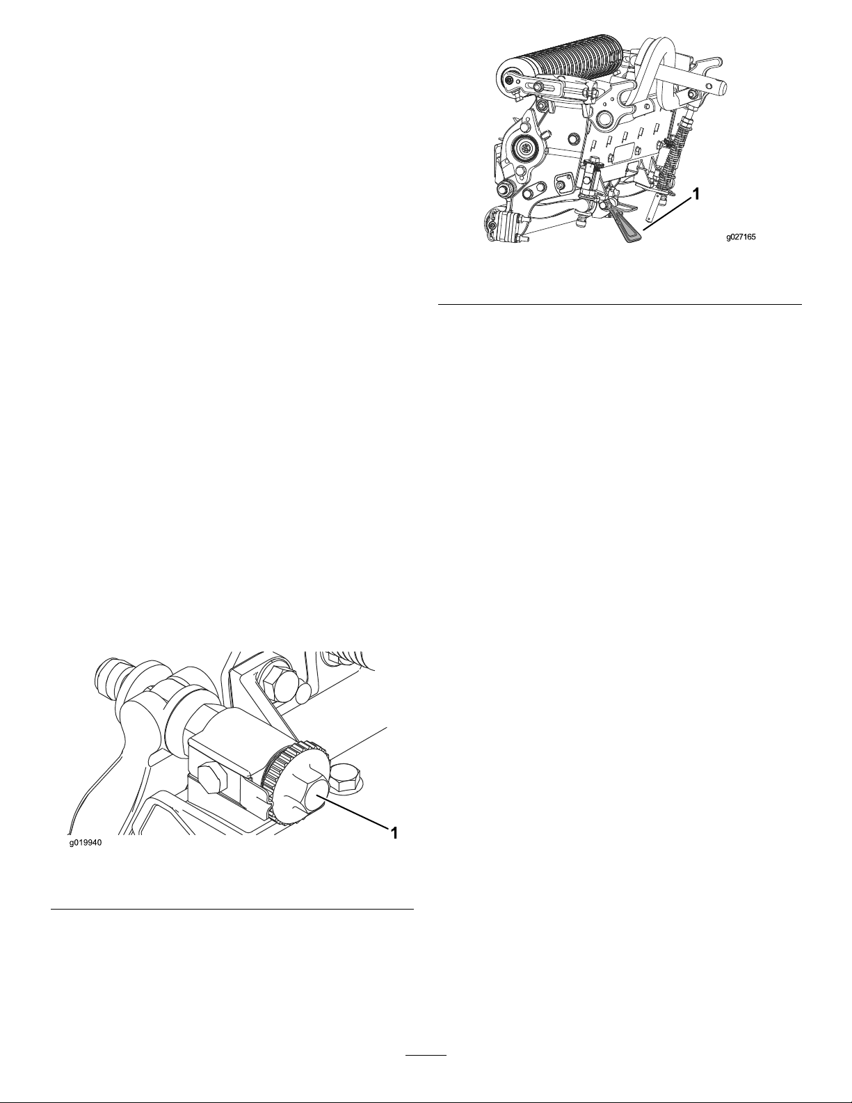
2.Loosennutongaugebar(Figure16)andsetadjusting
screwtodesiredheight-of-cut.
3.Height-of-cutbracket
Figure17
Important:Whensetproperly,therearandfront
rollerswillcontactthegaugebarandthescrew
willbesnugagainstthebedknife.Thisensures
thattheheight-of-cutisidenticalatbothendsof
thebedknife.
6.Tightennutstosecureadjustment.
Note:Donotovertightennut.Tightenenoughto
removeplayfromwasher.
Usethefollowingcharttodeterminewhichbedknifeis
bestsuitedforthedesiredheightofcut.
Figure16
1.Gaugebar4.Holesusedforsetting
GroomerHOG
2.Heightadjustingscrew5.Holenotused
3.Nut
3.Measurethedistancebetweenthebottomofthescrew
headandthefaceofthebartogettheheight-of-cut.
4.Hookthescrewheadoncuttingedgeofbedknifeand
restrearendofbaronrearroller(Figure17).
5.Rotatetheadjustingscrewuntilthefrontrollercontacts
thegaugebar(Figure17).Adjustbothendsofroller
untilentirerollerisparalleltothebedknife.
Bedknife/HeightofCutChart
BedknifeBedknifeLip
EdgeMax®Low
HOC(03635)
LowHOC
(Optional)
Extended
EdgeMax®Low
HOC(Optional)
ExtendedLow
HOC(Optional)
EdgeMax®
(03634)
Standard
(Optional)
HeavyDuty
(Optional)
*WarmseasongrassesmayrequiretheLowHOC
bedknifefor12.7mm(0.500inches)andbelow.
(0.220inch)
(0.220inch)
(0.220inch)
(0.220inch)
(0.270inch)
(0.270inch)
(0.370inch)
Height
5.6mm
(0.250-0.500inch)
5.6mm
(0.250-0.500inch)
5.6mm
(0.250-0.500inch)
5.6mm
(0.250-0.500inch)
6.9mm
(0.375-1.50inch)*
6.9mm
(0.375-1.50inch)*
9.3mm
(0.500-1.50inch)
HeightofCut
6.4-12.7mm
6.4-12.7mm
6.4-12.7mm
6.4-12.7mm
9.5-38.1mm
9.5-38.1mm
12.7-38.1mm
12
Page 13

Figure18
1.BedknifeLipHeight
AdjustingtheTurfCompensation
Settings
Theturfcompensationspringtransferstheweightfromthe
fronttotherearroller.(Thishelpstoreduceawavepattern
intheturf,alsoknownasmarcellingorbobbing.)
Important:Makespringadjustmentswiththecutting
unitmountedtothetractionunit,pointingstraight
aheadandloweredtotheshopoor.
1.Makesurethatthehairpincotterisinstalledintherear
holeinthespringrod(Figure19).
Thepreciseadjustmentpossiblewiththedualknob/bedbar
designgivesthenecessarycontroltoprovideacontinual
self-sharpeningaction-thusmaintainingsharpcuttingedges,
ensuringgoodquality-of-cut,andgreatlyreducingtheneed
forroutinebacklapping.
Priortomowingeachday ,orasrequired,eachcuttingunit
mustbecheckedtoverifyproperbedknife-to-reelcontact.
Thismustbeperformedeventhoughqualityofcutis
acceptable.
1.Lowerthecuttingunitsontoahardsurface,shutoff
theengine,andremovetheignitionkey.
2.Slowlyrotatethereelinareversedirection,listening
forreel-to-bedknifecontact.
Ifnocontactisevident,turnthebedknifeadjustingknobs
clockwise,oneclickatatime,untillightcontactisfeltand
heard.
Thereelmustcutonesheetofpaper,wheninsertedataright
angletothebedknife,atbothendsandatthecenterofthe
reel;refertostep12andFigure10in(page)
Theadjustmentknobshavedetentescorrespondingto0.022
mm(0.0009inch)bedknifemovementforeachindexed
position.
Figure19
1.Turfcompensationspring3.Springrod
2.Hairpincotter4.Hexnuts
2.Tightenthehexnutsonthefrontendofthespringrod
untilthecompressedlengthofthespringis15.9cm
(6.25inches)(Figure19).
Note:Whenoperatingthemachineonroughterrain,
decreasethespringlengthby12.7mm(1/2inch).
Note:Theturfcompensationsettingwillneedtobe
resetiftheHOCsettingortheaggressiveness-of-cut
settingischanged.
Ifexcessivecontact/reeldragisevidentitwillbeeither
necessarytobacklap,refacethefrontofthebedknife,or
regrindthecuttingunittoachievethesharpedgesneededfor
precisioncutting(RefertotheToroManualforSharpening
ReelandRotaryMowers).
Lightcontactispreferredatalltimes.Iflightcontactisnot
maintained,thebedknife/reeledgeswillnotsufciently
self-sharpenanddullcuttingedgeswillresultafteraperiodof
operation.Ifexcessivecontactismaintained,bedknife/reel
wearwillbeaccelerated,unevenwearcanresult,andquality
ofcutmaybeadverselyaffected.
Asthereelbladescontinuetorunagainstthebedknife,a
slightburrwillappearonthefrontcuttingedgesurfacealong
thefulllengthofthebedknife.Youcanremoveburrsand
improvecuttingbyoccasionallyrunningaleacrossthefront
edge.
Afterextendedrunning,aridgewilleventuallydevelopat
bothendsofthebedknife.Thesenotchesmustberounded
offorledushwiththecuttingedgeofthebedknifeto
ensuresmoothoperation.
Overtime,thechamfer(Figure20)willneedtobereground
asitisonlydesignedtolast40%ofthebedknifelife.
CheckingandAdjustingtheCutting
Unit
Thedualknobbedknife-to-reeladjustmentsystem
incorporatedinthiscuttingunitsimpliestheadjustment
procedureneededtodeliveroptimummowingperformance.
13
Page 14

Figure20
1.Lead-inchamferonrightendofbedknife
Donotmakelead-inchamfertoolargeasitmaycauseturf
tufting.
14
Page 15

ServicingtheBedknife
2
3
g027268
1
Thebedknifeservicelimitsarelistedinthefollowingcharts.
Important:Operatingthecuttingunitwiththebedknifebelowtheservicelimitmayresultinpoorafter-cut
appearanceandreducethestructuralintegrityofthebedknifeforimpacts.
BedknifeServiceLimitChart
Bedknife
EdgeMax®LowHOC
(model03635)
LowHOC(Optional)
ExtendedEdgeMax®
LowHOC(Optional)
ExtendedLowHOC
(Optional)
EdgeMax®
(model03634)
Standard(Optional)
HeavyDuty(Optional)
PartNo.
127–71325.6mm
110-40845.6mm
119–42805.6mm
120–16405.6mm
108-90956.9mm
108-90966.9mm
110-40749.3mm
RecommendedT opandFrontBedknifeGrindAngles
(Figure21)
BedknifeLipHeight*ServiceLimit*GrindAngles
(0.220inch)
(0.220inch)
(0.220inch)
(0.220inch)
(0.270inch)
(0.270inch)
(0.370inch)
6.4-12.7mm
(0.250-0.500inch)
4.8mm
(0.190inch)
4.8mm
(0.190inch)
4.8mm
(0.190inch)
4.8mm
(0.190inch)
4.8mm
(0.190inch)
4.8mm
(0.190inch)
Top/FrontAngles
10/5Degrees
10/5Degrees
10/10Degrees
10/10Degrees
10/5Degrees
10/5Degrees
10/5Degrees
Figure21
1.Bedknifeservicelimit*
2.Topgrindangle
3.Frontgrindangle
Note:Allbedknifeservicelimitmeasurementsreferencethe
bottomofthebedknife(Figure22)
Figure22
15
Page 16

Maintenance
ServicingtheBedbar
Lubrication
Eachcuttingunithas5greasettings(Figure23)thatmustbe
lubricatedregularlywithNo.2general-purposelithium-base
grease.
Thereare2lubricationpointsonthefrontroller,rearroller,
and1atthereelmotorspline.
Note:Lubricatingcuttingunitsimmediatelyafter
washinghelpspurgewateroutofbearingsandincreases
bearinglife.
1.Wipeeachgreasettingwithacleanrag.
2.Applygreaseuntilcleangreaseisseencomingoutof
rollersealsandbearingreliefvalve.
3.Wipeexcessgreaseaway.
RemovingtheBedbar
1.Turnbedbaradjusterscrewscounterclockwisetoback
thebedknifeawayfromreel(Figure24).
Figure24
1.Bedbaradjustingscrew3.Washer
2.Bedbar
2.Backoutthespringtensionnut,untilthewasherisno
longertensionedagainstthebedbar(Figure24).
3.Oneachsideofthemachine,loosenthelocknut
securingthebedbarbolt(Figure25).
4.Springtensionnut
Figure23
Greasettinglocationsonthereelmotorside.
Figure25
1.Bedbarbolt2.Locknut
4.Removeeachbedbarboltallowingbedbartobepulled
downwardandremovedfrommachinebolt(Figure25).
Note:Accountfor2nylonand1stampedsteel
washersoneachendofbedbar(Figure26).
Figure26
1.Bedbarbolt
2.Nut4.Nylonwasher
3.Steelwasher
16
Page 17

AssemblingtheBedbar
1.Installthebedbar,positioningthemountingears
betweenthewasherandbedbaradjuster.
2.Securethebedbartoeachsideplatewiththebedbar
bolts(nutsonbolts)andthe6washers.
Note:Positionanylonwasheroneachsideoftheside
plateboss.Placeasteelwasheroutsideeachofthe
nylonwashers(Figure26).
3.Torquethebedbarboltsto37-45N-m(27–33ft-lbs).
Note:Tightenthelocknutsuntiltheoutsidesteel
washerstopsrotatingandtheendplayisremovedbut,
donotovertightenordeectthesideplates.Washers
ontheinsidemayhaveagap.
4.Tightenthespringtensionnutuntilthespringis
collapsed,thenbackoff1/2turn(Figure27).
Figure27
1.Springtensionnut2.Spring
17
Page 18

ServicingtheRoller
TherollerRebuildKitandtheRollerRebuildToolKit
(Figure28)areavailableforservicingtheroller.TheRoller
RebuildKitincludesallthebearings,bearingnuts,innerseals
andoutersealstorebuildaroller.TheRollerRebuildTool
Kitincludesallthetoolsandtheinstallationinstructions
requiredtorebuildarollerwiththerollerrebuildkit.Refer
toyourPart’sCatalogorcontactyourAuthorizedDistributor
forassistance.
Figure28
1.RollerRebuildKit(PartNo.1 14–5430)
2.RollerRebuildToolKit(PartNo.1 15–0803)
3.Innerseal8.Washer
4.Bearing
5.Outerseal
6.Bearingnut
7.Innersealtool
9.Bearing/outersealtool
18
Page 19

Notes:
19
Page 20

Notes:
20
Page 21

Notes:
21
Page 22

DeclarationofIncorporation
TheT oroCompany,81 11LyndaleAve.South,Bloomington,MN,USAdeclaresthatthefollowingunit(s)
conform(s)tothedirectiveslisted,wheninstalledinaccordancewiththeaccompanyinginstructionsontocertain
ToromodelsasindicatedontherelevantDeclarationsofConformity.
ModelNo.
03634315000001andUp
03695315000001andUp
SerialNo.
ProductDescriptionInvoiceDescription
8-BladeDPACuttingUnit
with5inReel,Reelmaster
5010-H/5210/5410Series
TractionUnit
11-BladeDP ACuttingUnit
with5inReel,Reelmaster
5010-H/5210/5410Series
TractionUnit
22IN5-IN8-BLDDPACU
[5010HYBRID]
22IN5-IN11-BLDDPACU
[5010HYBRID]
GeneralDescription
CuttingUnit2006/42/EC
CuttingUnit2006/42/EC
Directive
RelevanttechnicaldocumentationhasbeencompiledasrequiredperPartBofAnnexVIIof2006/42/EC.
Wewillundertaketotransmit,inresponsetorequestsbynationalauthorities,relevantinformationonthispartly
completedmachinery.Themethodoftransmissionshallbeelectronictransmittal.
ThismachineryshallnotbeputintoserviceuntilincorporatedintoapprovedToromodelsasindicatedonthe
associatedDeclarationofConformityandinaccordancewithallinstructions,wherebyitcanbedeclaredin
conformitywithallrelevantDirectives.
Certied:EUTechnicalContact:
PeterT etteroo
ToroEuropeNV
B-2260Oevel-Westerloo
Belgium
DavidKlisTel.003214562960
Sr.EngineeringManager
811 1LyndaleAve.South
Bloomington,MN55420,USA
May29,2012
Fax003214581911
22
Page 23

InternationalDistributorList
Distributor:
AgrolancKft
BalamaPrimaEngineeringEquip.HongKong85221552163
B-RayCorporation
CascoSalesCompany
CeresS.A.CostaRica
CSSCTurfEquipment(pvt)Ltd.SriLanka
CyrilJohnston&Co.
CyrilJohnston&Co.RepublicofIreland
EquiverMexico525553995444ParklandProductsLtd.NewZealand6433493760
FemcoS.A.Guatemala
ForGarderOU
G.Y .K.CompanyLtd.
GeomechanikiofAthensGreece
GolfinternationalTurizm
GuandongGoldenStarChina
HakoGroundandGardenSweden
HakoGroundandGarden
HayterLimited(U.K.)
HydroturfInt.CoDubai
HydroturfEgyptLLC
IrrimacPortugal351212388260ToroEuropeNVBelgium3214562960
IrrigationProductsInt'lPvtLtd.India0091442449
JeanHeybroekb.v.Netherlands3130639461 1VictusEmakPoland48618238369
Country:
Hungary3627539640
Korea82325512076
PuertoRico7877888383
NorthernIreland442890813121
Estonia3723846060
Japan81726325861
Turkey902163365993Riversa
Norway4722907760
UnitedKingdom441279723444
UnitedArabEmirates97143479479T-MarktLogisticsLtd.Hungary3626525500
Egypt2025194308ToroAustraliaAustralia61395807355
PhoneNumber:Distributor:
5062391138
94112746100
442890813121
5024423277
30109350054
862087651338
4635100000
4387
Country:
MaquiverS.A.Colombia
MaruyamaMfg.Co.Inc.
Mountelda.s.CzechRepublic
Mountelda.s.Slovakia
MunditolS.A.
NormaGarden
OslingerTurfEquipmentSA
OyHakoGroundandGarden
Ab
Perfetto
PratoverdeSRL.
Prochaska&Cie
RTCohen2004Ltd.
LelyTurfcare
SolvertS.A.S.
SpyprosStavrinidesLimitedCyprus
SurgeSystemsIndiaLimited
ValtechMorocco21253766
Japan81332522285
Argentina54114821
Russia74954116120
Ecuador59342396970
Finland35898700733
Poland48618208416
Italy390499128
Austria4312785100
Israel97298617979
Spain
Denmark4566109200
France331308177
India911292299901
Phone
Number:
5712364079
420255704
220
420255704
220
9999
128
34952837500
00
35722434131
3636
EuropeanPrivacyNotice
TheInformationToroCollects
ToroWarrantyCompany(Toro)respectsyourprivacy.Inordertoprocessyourwarrantyclaimandcontactyouintheeventofaproductrecall,weaskyou
tosharecertainpersonalinformationwithus,eitherdirectlyorthroughyourlocalT orocompanyordealer.
TheT orowarrantysystemishostedonserverslocatedwithintheUnitedStateswhereprivacylawmaynotprovidethesameprotectionasapplies
inyourcountry.
BYSHARINGYOURPERSONALINFORMATIONWITHUS,YOUARECONSENTINGTOTHEPROCESSINGOFYOURPERSONALINFORMATION
ASDESCRIBEDINTHISPRIV ACYNOTICE.
TheWayT oroUsesInformation
Toromayuseyourpersonalinformationtoprocesswarrantyclaims,tocontactyouintheeventofaproductrecallandforanyotherpurposewhichwetell
youabout.ToromayshareyourinformationwithT oro'safliates,dealersorotherbusinesspartnersinconnectionwithanyoftheseactivities.Wewillnot
sellyourpersonalinformationtoanyothercompany.Wereservetherighttodisclosepersonalinformationinordertocomplywithapplicablelawsand
withrequestsbytheappropriateauthorities,tooperateoursystemsproperlyorforourownprotectionorthatofotherusers.
RetentionofyourPersonalInformation
Wewillkeepyourpersonalinformationaslongasweneeditforthepurposesforwhichitwasoriginallycollectedorforotherlegitimatepurposes
(suchasregulatorycompliance),orasrequiredbyapplicablelaw .
Toro'sCommitmenttoSecurityofYourPersonalInformation
Wetakereasonableprecautionsinordertoprotectthesecurityofyourpersonalinformation.Wealsotakestepstomaintaintheaccuracyandcurrent
statusofpersonalinformation.
AccessandCorrectionofyourPersonalInformation
Ifyouwouldliketorevieworcorrectyourpersonalinformation,pleasecontactusbyemailatlegal@toro.com.
AustralianConsumerLaw
AustraliancustomerswillnddetailsrelatingtotheAustralianConsumerLaweitherinsidetheboxoratyourlocalToroDealer.
374-0269RevH
Page 24

ToroGeneralCommercialProductWarranty
ATwo-YearLimitedWarranty
ConditionsandProductsCovered
TheToroCompanyanditsafliate,T oroWarrantyCompany,pursuant
toanagreementbetweenthem,jointlywarrantyourT oroCommercial
product(“Product”)tobefreefromdefectsinmaterialsorworkmanship
fortwoyearsor1500operationalhours*,whicheveroccursrst.This
warrantyisapplicabletoallproductswiththeexceptionofAerators
(refertoseparatewarrantystatementsfortheseproducts).Wherea
warrantableconditionexists,wewillrepairtheProductatnocosttoyou
includingdiagnostics,labor,parts,andtransportation.Thiswarranty
beginsonthedatetheProductisdeliveredtotheoriginalretailpurchaser .
*Productequippedwithanhourmeter.
InstructionsforObtainingWarrantyService
YouareresponsiblefornotifyingtheCommercialProductsDistributoror
AuthorizedCommercialProductsDealerfromwhomyoupurchasedthe
Productassoonasyoubelieveawarrantableconditionexists.Ifyouneed
helplocatingaCommercialProductsDistributororAuthorizedDealer,or
ifyouhavequestionsregardingyourwarrantyrightsorresponsibilities,
youmaycontactusat:
ToroCommercialProductsServiceDepartment
ToroWarrantyCompany
811 1LyndaleAvenueSouth
Bloomington,MN55420-1196
952–888–8801or800–952–2740
E-mail:commercial.warranty@toro.com
OwnerResponsibilities
AstheProductowner,youareresponsibleforrequiredmaintenanceand
adjustmentsstatedinyourOperator'sManual.Failuretoperformrequired
maintenanceandadjustmentscanbegroundsfordisallowingawarranty
claim.
ItemsandConditionsNotCovered
Notallproductfailuresormalfunctionsthatoccurduringthewarranty
periodaredefectsinmaterialsorworkmanship.Thiswarrantydoesnot
coverthefollowing:
•Productfailureswhichresultfromtheuseofnon-T ororeplacement
parts,orfrominstallationanduseofadd-on,ormodiednon-Toro
brandedaccessoriesandproducts.Aseparatewarrantymaybe
providedbythemanufactureroftheseitems.
•Productfailureswhichresultfromfailuretoperformrecommended
maintenanceand/oradjustments.Failuretoproperlymaintainyour
ToroproductpertheRecommendedMaintenancelistedinthe
Operator’sManualcanresultinclaimsforwarrantybeingdenied.
•ProductfailureswhichresultfromoperatingtheProductinanabusive,
negligent,orrecklessmanner.
•Partssubjecttoconsumptionthroughuseunlessfoundtobedefective.
Examplesofpartswhichareconsumed,orusedup,duringnormal
Productoperationinclude,butarenotlimitedto,brakepadsand
linings,clutchlinings,blades,reels,rollersandbearings(sealedor
greasable),bedknives,sparkplugs,castorwheelsandbearings,tires,
lters,belts,andcertainsprayercomponentssuchasdiaphragms,
nozzles,andcheckvalves,etc.
•Failurescausedbyoutsideinuence.Conditionsconsideredtobe
outsideinuenceinclude,butarenotlimitedto,weather,storage
practices,contamination,useofunapprovedfuels,coolants,lubricants,
additives,fertilizers,water,orchemicals,etc.
•Failureorperformanceissuesduetotheuseoffuels(e.g.gasoline,
diesel,orbiodiesel)thatdonotconformtotheirrespectiveindustry
standards.
•Normalnoise,vibration,wearandtear ,anddeterioration.
•Normal“wearandtear”includes,butisnotlimitedto,damagetoseats
duetowearorabrasion,wornpaintedsurfaces,scratcheddecalsor
windows,etc.
Parts
Partsscheduledforreplacementasrequiredmaintenancearewarranted
fortheperiodoftimeuptothescheduledreplacementtimeforthatpart.
Partsreplacedunderthiswarrantyarecoveredforthedurationofthe
originalproductwarrantyandbecomethepropertyofT oro.T orowillmake
thenaldecisionwhethertorepairanyexistingpartorassemblyorreplace
it.T oromayuseremanufacturedpartsforwarrantyrepairs.
DeepCycleandLithium-IonBatteryWarranty:
DeepcycleandLithium-Ionbatterieshaveaspeciedtotalnumberof
kilowatt-hourstheycandeliverduringtheirlifetime.Operating,recharging,
andmaintenancetechniquescanextendorreducetotalbatterylife.Asthe
batteriesinthisproductareconsumed,theamountofusefulworkbetween
chargingintervalswillslowlydecreaseuntilthebatteryiscompletelyworn
out.Replacementofwornoutbatteries,duetonormalconsumption,
istheresponsibilityoftheproductowner.Batteryreplacementmaybe
requiredduringthenormalproductwarrantyperiodatowner’sexpense.
Note:(Lithium-Ionbatteryonly):ALithium-Ionbatteryhasapartonly
proratedwarrantybeginningyear3throughyear5basedonthetime
inserviceandkilowatthoursused.RefertotheOperator'sManualfor
additionalinformation.
MaintenanceisatOwner’sExpense
Enginetune-up,lubrication,cleaningandpolishing,replacementoflters,
coolant,andcompletingrecommendedmaintenancearesomeofthe
normalservicesT oroproductsrequirethatareattheowner’sexpense.
GeneralConditions
RepairbyanAuthorizedToroDistributororDealerisyoursoleremedy
underthiswarranty.
NeitherTheToroCompanynorToroWarrantyCompanyisliablefor
indirect,incidentalorconsequentialdamagesinconnectionwiththe
useoftheToroProductscoveredbythiswarranty,includingany
costorexpenseofprovidingsubstituteequipmentorserviceduring
reasonableperiodsofmalfunctionornon-usependingcompletion
ofrepairsunderthiswarranty.ExceptfortheEmissionswarranty
referencedbelow,ifapplicable,thereisnootherexpresswarranty.All
impliedwarrantiesofmerchantabilityandtnessforusearelimitedto
thedurationofthisexpresswarranty.
Somestatesdonotallowexclusionsofincidentalorconsequential
damages,orlimitationsonhowlonganimpliedwarrantylasts,sotheabove
exclusionsandlimitationsmaynotapplytoyou.Thiswarrantygivesyou
speciclegalrights,andyoumayalsohaveotherrightswhichvaryfrom
statetostate.
Noteregardingenginewarranty:
TheEmissionsControlSystemonyourProductmaybecoveredby
aseparatewarrantymeetingrequirementsestablishedbytheU.S.
EnvironmentalProtectionAgency(EP A)and/ortheCaliforniaAirResources
Board(CARB).Thehourlimitationssetforthabovedonotapplytothe
EmissionsControlSystemWarranty.RefertotheEngineEmissionControl
WarrantyStatementsuppliedwithyourproductorcontainedintheengine
manufacturer’sdocumentationfordetails
CountriesOtherthantheUnitedStatesorCanada
CustomerswhohavepurchasedT oroproductsexportedfromtheUnitedStatesorCanadashouldcontacttheirT oroDistributor(Dealer)toobtain
guaranteepoliciesforyourcountry ,province,orstate.IfforanyreasonyouaredissatisedwithyourDistributor'sserviceorhavedifcultyobtaining
guaranteeinformation,contacttheT oroimporter.
374-0253RevC
 Loading...