

Page 1

FormNo.3397-860RevB
22-inch8-Bladeor11-BladeDPA
CuttingUnitwith5inReel
Reelmaster
ModelNo.03621—SerialNo.315000001andUp
ModelNo.03623—SerialNo.315000001andUp
®
5010SeriesTractionUnit
Registeratwww.T oro.com.
OriginalInstructions(EN)
*3397-860*B
Page 2

WARNING
CALIFORNIA
Proposition65Warning
Thisproductcontainsachemicalorchemicals
knowntotheStateofCaliforniatocausecancer,
birthdefects,orreproductiveharm.
ThisproductcomplieswithallrelevantEuropeandirectives.
Fordetails,pleaseseetheDeclarationofIncorporation(DOI)
atthebackofthispublication.
ModelNo.
SerialNo.
Thismanualidentiespotentialhazardsandhassafety
messagesidentiedbythesafety-alertsymbol(Figure2),
whichsignalsahazardthatmaycauseseriousinjuryordeath
ifyoudonotfollowtherecommendedprecautions.
Figure2
1.Safety-alertsymbol
Introduction
Readthisinformationcarefullytolearnhowtooperateand
maintainyourproductproperlyandtoavoidinjuryand
productdamage.Youareresponsibleforoperatingthe
productproperlyandsafely.
YoumaycontactTorodirectlyatwww .Toro.comforproduct
safetyandoperationtrainingmaterials,accessoryinformation,
helpndingadealer,ortoregisteryourproduct.
Wheneveryouneedservice,genuineT oroparts,oradditional
information,contactanAuthorizedServiceDealerorToro
CustomerServiceandhavethemodelandserialnumbersof
yourproductready.Figure1identiesthelocationofthe
modelandserialnumbersontheproduct.Writethenumbers
inthespaceprovided.
Thismanualuses2wordstohighlightinformation.
Importantcallsattentiontospecialmechanicalinformation
andNoteemphasizesgeneralinformationworthyofspecial
attention.
Contents
Safety...........................................................................3
SafetyandInstructionalDecals.................................3
Setup............................................................................4
1InspectingtheCuttingUnit....................................4
2UsingtheCutting-UnitKickstand...........................4
3AdjustingtheRearShield.......................................5
4InstallingtheLooseParts.......................................5
ProductOverview..........................................................7
Specications.........................................................7
Attachments/Accessories.........................................7
Operation.....................................................................7
MakingAdjustments................................................7
Height-of-CutChartTerms......................................9
Height-of-CutChart...............................................10
Maintenance.................................................................14
LubricatingtheMachine..........................................14
Relief-GrindingtheReel..........................................14
ServicingtheBedknife............................................15
ServicingtheBedbar...............................................16
ServicingtheHDDualPointAdjusters
(DPA)...............................................................17
ServicingtheRoller.................................................19
1.Locationofthemodelandserialnumbers
©2016—TheToro®Company
8111LyndaleAvenueSouth
Bloomington,MN55420
Figure1
Contactusatwww.Toro.com.
2
PrintedintheUSA
AllRightsReserved
Page 3
Safety
ThismachinehasbeendesignedinaccordancewithENISO
5395:2013andANSIB71.4-2012.
Improperuseormaintenanceofthisequipmentcan
resultininjuryordeath.T oreducethepotentialfor
injuryordeath,complywiththefollowingsafety
instructions.
•Read,understand,andfollowallinstructionsinthe
tractionunitOperator’sManualbeforeoperatingthecutting
unit.
•Read,understand,andfollowallinstructionsinthis
Operator’sManualbeforeoperatingthecuttingunit.
•Neverallowchildrenoruntrainedpersonneltooperate
orservicethemachine.Localregulationsmayrestrictthe
ageoftheoperator.Theownerisresponsiblefortraining
alloperatorsandmechanics.
•Neveroperatethecuttingunitswhensick,tired,orunder
theinuenceofdrugsoralcohol.
•Keepallshieldsandsafetydevicesinplace.Ifashield,a
safetydevice,oradecalisillegibleordamaged,repairor
replaceitbeforeresumingoperation.Also,tightenany
loosenuts,bolts,andscrewstoensurethatthecutting
unitisinsafeoperatingcondition.
•Removealldebrisorotherobjectsthatmightbepicked
upandthrownbythereelbladesofthecuttingunit.Keep
allbystandersawayfromtheworkingarea.
•Ifthecuttingbladesstrikeasolidobjectortheunit
vibratesabnormally,stopandshuttheengineoff.Check
thecuttingunitfordamagedparts.Repairanydamage
beforestartingandoperatingthecuttingunit.
•Lowerthecuttingunitstothegroundandremovethekey
fromtheignitionswitchwheneveryouleavethemachine
unattended.
•Besurethatthecuttingunitsareinsafeoperating
conditionbykeepingnuts,bolts,andscrewstight.
•Removethekeyfromtheswitchtopreventaccidental
startingoftheenginewhenservicing,adjusting,orstoring
themachine.
•Performonlythosemaintenanceinstructionsdescribedin
thismanual.Ifmajorrepairsareeverneededorassistance
isdesired,contactanAuthorizedT oroDistributor.
•Toensureoptimumperformanceandcontinuedsafety
certicationofthemachine,useonlygenuineToro
replacementpartsandaccessories.Replacementparts
andaccessoriesmadebyothermanufacturerscouldbe
dangerous,andsuchusecouldvoidtheproductwarranty.
•Wearappropriateclothing,includingsafetyglasses,
slip-resistant,substantialfootprotection,andhearing
protection.Tiebacklonghairanddonotwearjewelry.
SafetyandInstructionalDecals
Safetydecalsandinstructionsareeasilyvisibletotheoperatorandarelocatednearanyareaofpotential
danger.Replaceanydecalthatisdamagedorlost.
93–6688
1.Warning—readthe
Operator’sManualbefore
performingmaintenance.
2.Cuttinghazardofhandor
foot—stoptheengineand
waitforallmovingpartsto
stop.
3
Page 4

Setup
LooseParts
Usethechartbelowtoverifythatallpartshavebeenshipped.
ProcedureDescription
1
2
3
4
Cuttingunit
Nopartsrequired
Nopartsrequired
Straightgreasetting
O-ring
Screws
MediaandAdditionalParts
Description
PartsCatalog
Operator'sManual
Note:Determinetheleftandrightsidesofthemachine
fromthenormaloperatingposition.
Qty.
Qty.
1Inspectthecuttingunit.
–
–
1
1
2
1
1
Reviewthesematerialsandsavethemforfuturereference.
Usethekickstandwhentippingthe
cuttingunit.
Adjusttherearshield.
Installthelooseparts.
Use
Use
2
1
InspectingtheCuttingUnit
Partsneededforthisprocedure:
1
Cuttingunit
Procedure
Afteryouremovethecuttingunitfromthebox,inspectthe
following:
1.Checkeachendofthereelforgrease.
Note:Greaseshouldbevisiblyevidentinthereel
bearingsandinternalsplinesofthereelshaft.
2.Ensurethatallnutsandboltsaresecurelytightened.
3.Makesurethatthecarrier-framesuspensionoperates
freelyanddoesnotbindwhenyoumoveitbackand
forth.
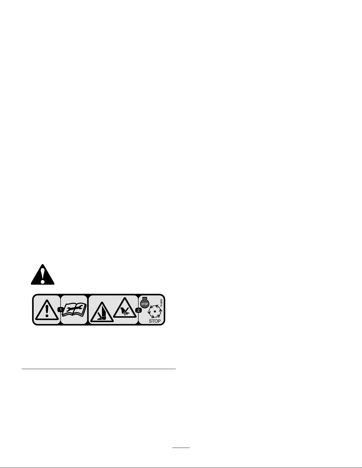
UsingtheCutting-Unit Kickstand
NoPartsRequired
Procedure
Wheneverthecuttingunithastobetippedtoexposethe
bedknifeorthereel,propuptherearofthecuttingunitwith
thekickstand(suppliedwiththetractionunit)tomakesure
thatthenutsonthebackendofthebedbar-adjustingscrews
arenotrestingontheworksurface(Figure3).
4
Page 5
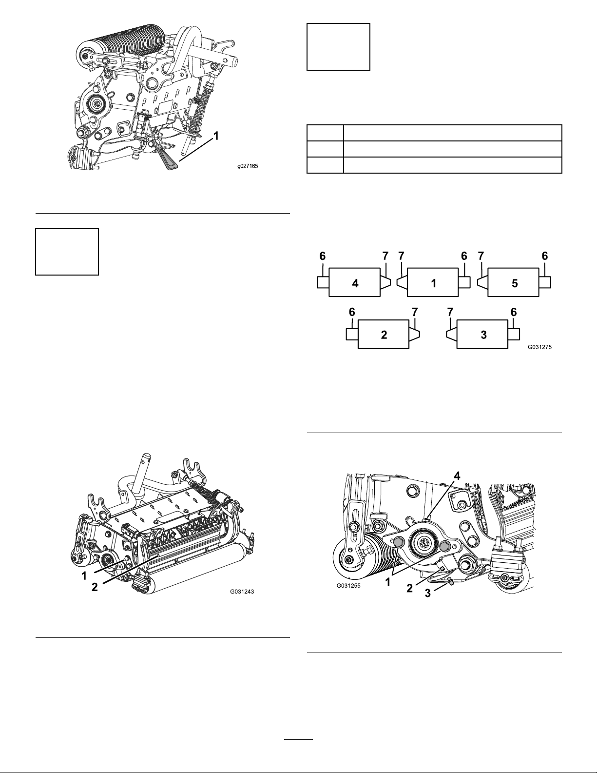
Figure3
4
InstallingtheLooseParts
Partsneededforthisprocedure:
1
Straightgreasetting
1
O-ring
2
Screws
1.Cutting-unitkickstand
3
AdjustingtheRearShield
NoPartsRequired
Procedure
Undermostconditions,bestdispersionisattainedwhenthe
rearshieldisclosed(frontdischarge).Whenconditionsare
heavyorwet,youcanopentherearshield.
Toopentherearshield(Figure4),loosenthecapscrew
securingtheshieldtotheleftsideplate,rotatetheshieldto
theopenposition,andtightenthecapscrew.
Procedure
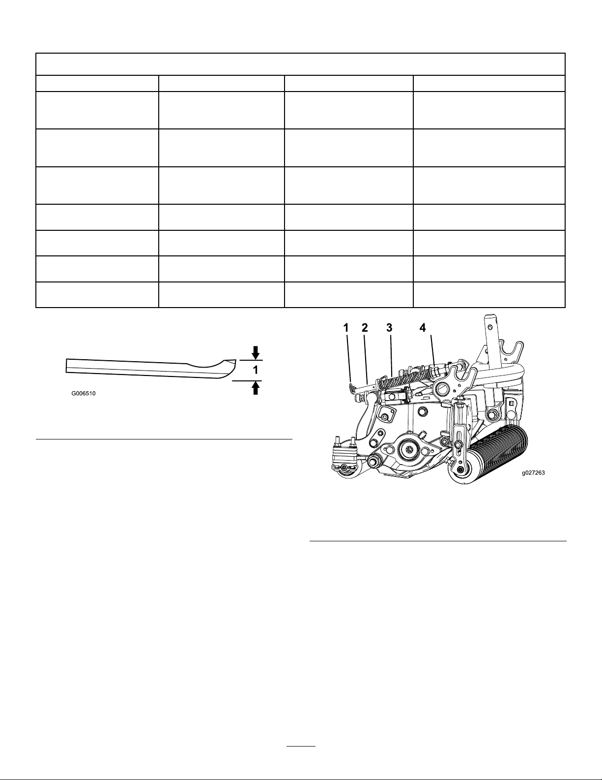
Installthegreasettingonthereel-motorsideofthecutting
unit.UseFigure5todeterminethepositionofthereel
motors.
Figure5
1.Cuttingunit15.Cuttingunit5
2.Cuttingunit2
3.Cuttingunit3
4.Cuttingunit4
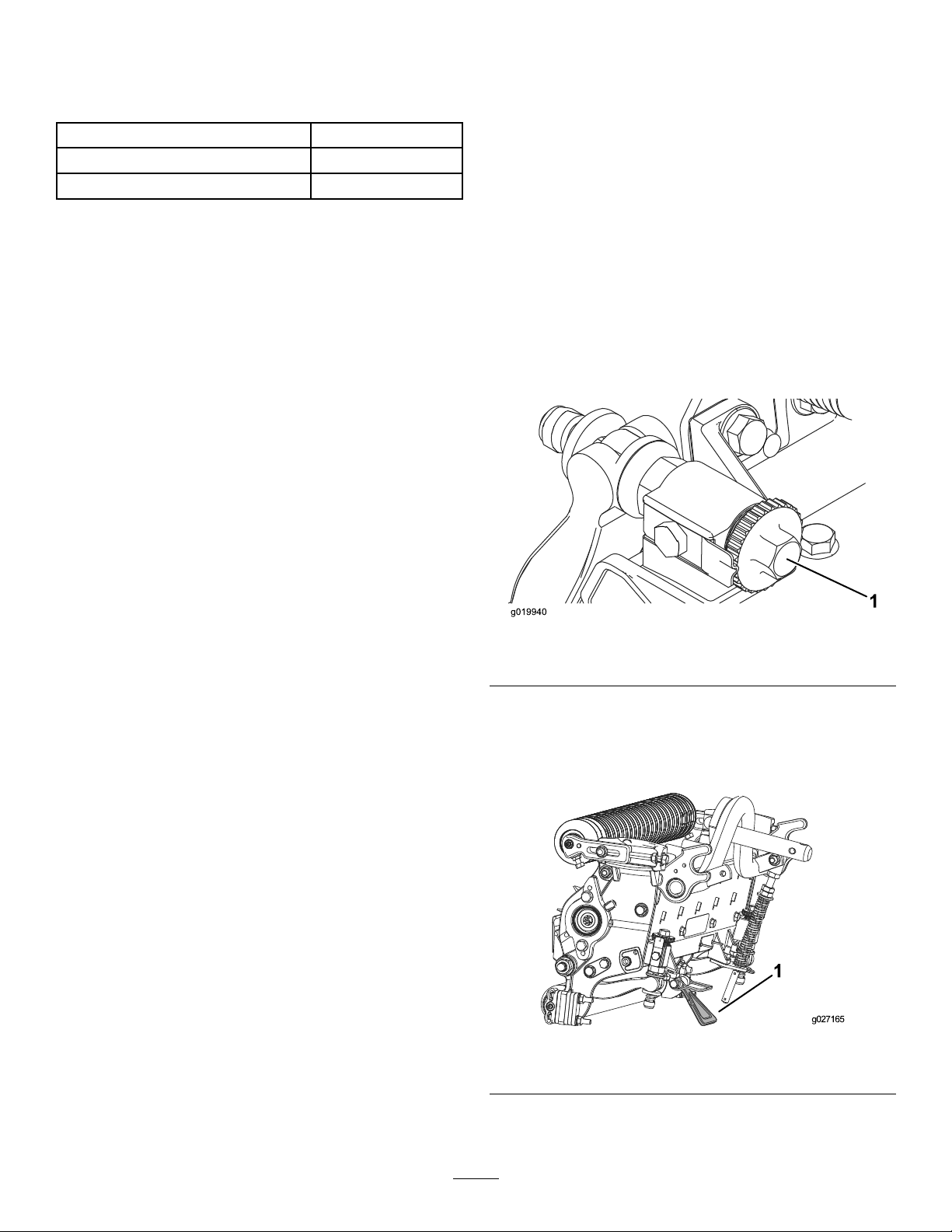
1.Removeanddiscardthesetscrewonthereel-motor
sideplate(Figure6).
6.Reelmotor
7.Weight
1.Rearshield
Figure4
2.Capscrew
Figure6
1.Bolt(2)3.Greasetting
2.Setscrew4.Greasevent
2.Installthestraightgreasetting(Figure6).
3.Iftherearenoboltsonthereel-motorsideplate,install
them(Figure6).
4.InstalltheO-ringonthereelmotor(Figure7).
5
Page 6

Figure7
1.O-ring
5.Installthereelmotor.
6.Greasethesideplateuntilexcessgreasecomesoutthe
greasevent(Figure6).
6
Page 7
ProductOverview
Specications
ModelNumberNetWeight
03621
03623
Attachments/Accessories
AselectionofToro-approvedattachmentsandaccessoriesisavailableforusewiththemachinetoenhanceandexpand
itscapabilities.ContactyourAuthorizedServiceDealerorDistributororgotowww.Toro.comforalistofallapproved
attachmentsandaccessories
TobestprotectyourinvestmentandmaintainoptimalperformanceofyourToroequipment,countonTorogenuineparts.
Whenitcomestoreliability,Torodeliversreplacementpartsdesignedtotheexactengineeringspecicationofourequipment.
Forpeaceofmind,insistonT orogenuineparts.
51kg(1 12lb)
52kg(1 16lb)
Operation
Note:Determinetheleftandrightsidesofthemachine
fromthenormaloperatingposition.
MakingAdjustments
AdjustingtheBedknifetotheReel
Usethisproceduretosetthebedknifetothereelandtocheck
theconditionofthereelandbedknifeandtheirinteraction.
Aftercompletingthisprocedure,alwaystestthecutting
unitperformanceunderyoureldconditions.Youmay
needtomakefurtheradjustmentstoobtainoptimalcutting
performance.
Important:Donotovertightenthebedknifetothereel
oryouwilldamageit.
•Afterbacklappingthecuttingunitorgrindingthereel,you
mayneedtomowwiththecuttingunitforafewminutes
andthenperformthisproceduretoadjustthebedknifeto
thereelasthereelandbedknifeadjusttoeachother.
•Youmayneedadditionaladjustmentsiftheturfis
extremelydenseoryourcuttingheightisverylow .
Youwillneedthefollowingtoolstocompletethisprocedure:
•Shim(0.002inch)—ToroPartNo.125-5611
•Cuttingperformancepaper—ToroPartNo.125-5610
Figure8
1.Bedbar-adjustingscrew
2.Tipthemowertoexposethebedknifeandreel.
Important:Makesurethatthenutsontheback
endofthebedbaradjustingscrewsarenotresting
ontheworksurface(Figure9).
1.Positionthecuttingunitonaat,levelworksurface.
Turnthebedbar-adjustingscrewscounterclockwiseto
ensurethatthebedbardoesnotcontactthereel(Figure
8).
Figure9
1.Cutting-unitkickstand
3.Rotatethereelsothatabladecrossesthebedknife
approximately25mm(1inch)infromtheendofthe
7
Page 8
bedknifeontherightsideofthecuttingunit.Putting
g027270
anidentifyingmarkonthisbladewillmakesubsequent
adjustmentseasier.Insertthe0.05mm(0.002inch)
shimbetweenthemarkedreelbladeandthebedknife
atthepointwherethebladecrossesthebedknife.
4.Turntherightbedbaradjusterclockwiseuntilyoufeel
lightpressure(i.e.,drag)ontheshim,thenbackoffthe
bedbaradjuster2clicksandremovetheshim.(Since
adjusting1sideofthecuttingunitaffectstheother
side,the2clicksprovidetheclearancethatyouneed
forwhenyouadjusttheotherside.)
Note:Ifthereisalargegap,drawbothsidescloserby
alternatelytighteningtherightandleftsides.
5.Slowlyrotatethereelsothatthesamebladethatyou
checkedontherightsideiscrossingthebedknife
approximately25mm(1inch)infromtheendofthe
bedknifeontheleftsideofthecuttingunit.
Note:Ifthereisexcessivereeldrag,eitherbacklap
orgrindthecuttingunittoachievethesharpedges
neededforprecisioncutting.
AdjustingtheRearRoller
1.Adjusttherearrollerbrackets(Figure11)tothedesired
height-of-cutrangebypositioningtherequiredamount
ofspacersbelowtheside-platemountingange(Figure
11)pertheHOCChart.
6.Turntheleftbedbaradjusterclockwiseuntilyoucan
slidetheshimthroughthereeltobedknifegapwith
lightdrag.
7.Returntotherightsideandadjustasnecessarytoget
lightdragontheshimbetweenthesamebladeand
bedknife.
8.Repeatsteps6and7untilyoucanslidetheshim
throughbothgapswithslightdrag,but1clickinon
bothsidespreventstheshimfrompassingthroughon
bothsides.Thebedknifeisnowparalleltothereel.
Note:Y oushouldnotneedtoperformthisprocedure
fordailyadjustments,butaftergrindingordisassembly.
9.Fromthisposition(i.e.,1clickinandashimnot
passingthrough)turnthebedbaradjustersclockwise2
clickseach.
Note:Eachclickturnedmovesthebedknife0.018
(0.0007inch).Donotovertightentheadjusting
screws.
10.Testthecuttingperformancebyinsertingalongstripof
cuttingperformancepaper(ToroPartNo.125-5610)
betweenthereelandthebedknife,perpendiculartothe
bedknife(Figure10).Slowlyrotatethereelforward;it
shouldcutthepaper.
Figure11
1.Spacer3.Side-platemountingange
2.Rollerbracket
2.Raisetherearofthecuttingunitandplaceablock
underthebedknife.
3.Removethe2nutssecuringeachrollerbracketand
spacertoeachside-platemountingange.
4.Lowertherollerandthescrewsfromtheside-plate
mountingangesandspacers.
5.Placespacersontoscrewsonrollerbrackets.
6.Securetherollerbracketandspacerstotheunderside
oftheside-platemountingangeswiththenuts
previouslyremoved.
7.Verifythatthebedknife-to-reelcontactiscorrect.Tip
themowertoexposethefrontandrearrollersandthe
bedknife.
Note:Thepositionoftherearrollertothereel
iscontrolledbythemachiningtolerancesofthe
assembledcomponentsandparallelingisnotrequired.
Alimitedamountofadjustmentispossiblebysetting
thecuttingunitonasurfaceplateandlooseningthe
side-platemountingbolts(Figure12).Adjustand
tightenthebolts.Torquetheboltsto37to45N∙m
(27to33ft-lb).
Figure10
Figure12
1.Side-platemountingbolts
8
Page 9

Height-of-CutChartTerms
Height-of-CutSetting(HOC)
Thiscorrespondstothedesiredheightofcut.
Bench-SetHeightofCut
Thisistheheightatwhichthetopedgeofthebedknifeisset
aboveaatlevelsurfacethatcontactsthebottomofboththe
frontandrearrollers.
RearSpacers
Thenumberofrearspacersdeterminestheaggressiveness
ofcutforthecuttingunit.Foragivenheightofcut,adding
spacersbelowtheside-platemountingangeincreasesthe
aggressivenessofthecuttingunit.Allcuttingunitsona
givenmachinemustbesettothesameaggressivenessofcut
(numberofrearspacers,ToroPartNo.119-0626);otherwise,
theafter-cutappearancecouldbenegativelyaffected(Figure
13).
ChainLinks
EffectiveHeightofCut
Thisistheactualheightthegrasshasbeencut.Foragiven
bench-setheightofcut,theactualheightofcutwillvary
dependingonthetypeofgrass,timeofyear,turf,andsoil
conditions.Thecutting-unitsetup(aggressivenessofcut,
rollers,bedknives,attachmentsinstalled,turf-compensation
settings,etc.)willalsoaffecttheeffectiveheightofcut.Check
theeffectiveheightofcutusingtheTurfEvaluator(Model
04399)regularlytodeterminethedesiredbench-setheight
ofcut.
AggressivenessofCut
Cuttingunitaggressivenessofcuthasasignicantimpact
ontheperformanceofthecuttingunit.Aggressivenessof
cutreferstotheangleofthebedkniferelativetotheground
(Figure13).
Thebestcuttingunitsetupisdependentonyourturf
conditionsanddesiredresults.Experiencewiththecutting
unitonyourturfwilldeterminethebestsettingtouse.You
canadjusttheaggressivenessofcutthroughoutthecutting
seasontoallowforvariousturfconditions.
Ingeneral,lesstonormalaggressivesettingsaremore
appropriateforwarm-seasongrasses(Bermuda,paspalum,
zoysia)whilecool-seasongrasses(bent,bluegrass,rye)may
requirenormaltomoreaggressivesetups.Moreaggressive
setupscutmoregrassoffbyallowingthespinningreeltopull
moregrassupintothebedknife.
Thelocationatwhichthelift-armchainisattacheddetermines
thepitchangleoftherearroller(Figure14).
Figure14
1.Liftchain
2.U-Bracket
3.Bottomhole
Groomer
Thesearetherecommendedheightofcutsettingswhena
groomerkitisinstalledonthecuttingunit.
1.Rearspacers
2.Side-platemountingange
Figure13
3.Aggressivenessofcut
9
Page 10

Height-of-CutChart
HOCSettingAggressivenessofCutNo.ofRearSpacersNo.ofChainLinksWithGroomerkits
0.64cm(0.250inches)
0.95cm(0.375inches)
1.27cm(0.500inches)
1.56cm(0.625inches)
1.91cm(0.750inches)
2.22cm(0.875inches)
2.54cm(1.000inch)
2.86cm(1.125inches)*
3.18cm(1.250inches)*
3.49cm(1.375inches)*
3.81cm(1.500inches)*
+IndicatestheU-bracket,onliftarm,ispositionedinthebottomhole(Figure14).
*HighHOCKit(Part110-9600)mustbeinstalled.ThefrontHOCbracketmustbepositionedinthetopside-platehole.
**YindicatesthatthiscombinationofHOCandspacerscanbeusedwithgroomers.
Less
Normal
More
Less
Normal
More
Less
Normal
More
Less
Normal
More
Less
Normal
More
Less
Normal
More
Less
Normal
More
Less
Normal
More
Less
Normal
More
Less
Normal
More
Less
Normal
More
0
0
1
0
1
2
0
1
2
1
2
3
2
3
4
2
3
4
3
4
5
4
5
6
4
5
6
4
5
6
5
6
7
3+
3+
3
4
3
3
4
3+
3
4
3
3
3+
3
3
4
3
3
3+
3
3
4
3
3
4
3
3
4
3
3
3+
3
3
installed**
Y
Y
-
Y
Y
-
Y
Y
Y
Y
Y
-
Y
Y
-
Y
Y
-
Y
Y
-
-
-
-
-
-
-
-
-
-
-
-
-
Note:Changing1chainlinkchangestherearrollerpitchanglemovementby7.0degrees.
Note:ChangingtheU-bracket,ontheliftarm,tothebottomholeadds3.5degreestotherearrollerpitchangle.
10
Page 11

AdjustingtheHeightofCut
Note:Forheightsofcutgreaterthan2.54cm(1inch)install
theHighHeight-of-CutKit.
1.Loosenthelocknutssecuringtheheight-of-cutbrackets
tothecutting-unitsideplates(Figure15).
Figure15
1.Adjustingscrew
2.Locknut
3.Height-of-cutbracket
Figure17
Important:Whensetproperly,therearandfront
rollerswillcontactthegaugebarandthescrew
willbesnugagainstthebedknife.Thisensures
thattheheightofcutisidenticalatbothendsof
thebedknife.
5.Tightenthenutstosecuretheadjustment.Donot
overtightenthenuts—justenoughtoremoveanyplay
fromthewasher.
2.Loosenthenutonthegaugebar(Figure16)andset
theadjustingscrewtothedesiredheightofcut.The
distancebetweenthebottomofthescrewheadandthe
faceofthebaristheheightofcut.
Figure16
1.Gaugebar4.Holesusedforsettingthe
2.Height-adjustingscrew5.Holenotused
3.Nut
heightofgroom(HOG)
3.Hookthescrewheadonthecuttingedgeofthe
bedknifeandresttherearendofthebarontherear
roller(Figure17).
4.Rotatetheadjustingscrewuntilthefrontrollercontacts
thegaugebar(Figure17).Adjustbothendsofroller
untiltheentirerollerisparalleltothebedknife.
11
Page 12
Usethefollowingcharttodeterminewhichbedknifeis
bestsuitedforthedesiredheightofcut.
Bedknife/HeightofCutChart
Bedknife
LowHOC(Optional)
EdgeMax®LowHOC
(Model03623)
ExtendedLowHOC
(Optional)
ExtendedEdgeMax®Low
HOC(Optional)
EdgeMax®(Model03621)
Standard(Optional)
HeavyDuty(Optional)
PartNo.
110-40845.6mm
127-71325.6mm
120-16405.6mm
119-42805.6mm
108-90956.9mm
108-90966.9mm
110-40749.3mm
*Warm-seasongrassesmayrequiretheLowHOC
bedknifefor12.7mm(0.500inch)andbelow.
BedknifeLipHeightHeightofCut
(0.220inch)
(0.220inch)
(0.220inch)
(0.220inch)
(0.270inch)
(0.270inch)
(0.370inch)
6.4to12.7mm
(0.250to0.500inch)
6.4to12.7mm
(0.250to0.500inch)
6.4to12.7mm
(0.250to0.500inch)
6.4to12.7mm
(0.250to0.500inch)
9.5to38.1mm
(0.375to1.50inches)*
9.5to38.1mm
(0.375to1.50inches)*
12.7to38.1mm
(0.500to1.50inches)
Figure18
1.Bedknifelipheight
AdjustingtheTurf-Compensation
Settings
Theturf-compensationspringtransferstheweightfromthe
fronttotherearroller.Thishelpstoreduceawavepatternin
theturf,alsoknownasmarcellingorbobbing.
Important:Makespringadjustmentswiththecutting
unitmountedtothetractionunit,pointingstraight
aheadandloweredtotheshopoor.
1.Makesurethatthehairpincotterisinstalledintherear
holeinthespringrod(Figure19).
Figure19
1.Turf-compensationspring3.Springrod
2.Hairpincotter4.Hexnuts
2.Tightenthehexnutsonthefrontendofthespringrod
untilthecompressedlengthofthespringis12.7cm(5
inches);refertoFigure19.
Note:Whenoperatingonroughterraindecreasethe
springlengthby1.3cm(1/2inch).Groundfollowing
willbeslightlydecreased.
Note:Youwillneedtoresettheturfcompensation
settingiftheHOCsettingortheaggressiveness-of-cut
settingischanged.
12
Page 13

CheckingandAdjustingtheCutting
Unit
Thedualknobbedknife-to-reeladjustmentsystem
incorporatedinthiscuttingunitsimpliestheadjustment
procedureneededtodeliveroptimummowingperformance.
Thepreciseadjustmentpossiblewiththedualknob/bedbar
designgivesthenecessarycontroltoprovideacontinual
self-sharpeningaction-thusmaintainingsharpcuttingedges,
ensuringgoodqualityofcut,andgreatlyreducingtheneed
forroutinebacklapping.
Priortomowingeachday,orasrequired,checkeachcutting
unittoverifyproperbedknife-to-reelcontact.Performthis
procedureevenifthequalityofcutisacceptable.
1.Slowlyrotatethereelinareversedirection,listening
forreel-to-bedknifecontact.
Note:Overtime,youwillneedtogrindthechamfer
(Figure21),asitisonlydesignedtolast40%ofthe
bedknifelife.
Figure21
Note:Theadjustmentknobshavedetents
correspondingto0.018mm(0.0007inch)bedknife
movementforeachindexedposition.Referto
AdjustingtheBedknifetotheReel(page7).
2.Testthecuttingperformancebyinsertingalongstrip
ofcuttingperformancepaper(ToroPart125-5610)
betweenthereelandthebedknife,perpendiculartothe
bedknife(Figure20).Slowlyrotatethereelforward;it
shouldcutthepaper.
Figure20
Note:Ifexcessivecontact/reeldragisevident,either
backlap,refacethefrontofthebedknife,orgrindthe
cuttingunittoachievethesharpedgesneededfor
precisioncutting;refertotheToroManualforSharpening
ReelandRotaryMowers,FormNo.09168SL.
1.Lead-inchamferonright
endofbedknife
2.6mm(0.25inch)
3.1.5mm(0.060inch)
Note:Donotmakethelead-inchamfertoolargeas
itmaycauseturftufting.
Important:Lightcontactispreferredatalltimes.
Ifyoudonotmaintainlightcontact,thebedknife
andreeledgeswillnotsufcientlyself-sharpen
andwilldullafteraperiodofoperation.Ifyou
maintainexcessivecontact,thebedknifeandreel
willwearquicker,wearunevenly,andthequality
ofcutmaybeadverselyaffected.
Note:Afterextendedrunning,aridgewilleventually
developatbothendsofthebedknife.Roundoffor
lethesenotchesushwiththecuttingedgeofthe
bedknifetoensuresmoothoperation.
13
Page 14
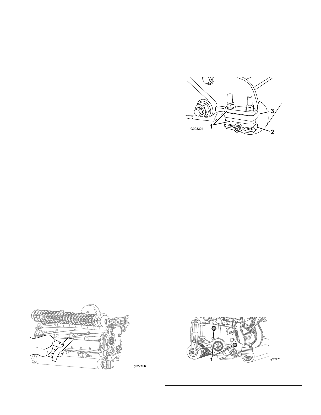
Maintenance
LubricatingtheMachine
Regularlylubricatethe6greasettingsofeachcuttingunit
(Figure22)withNo.2lithiumgrease.
Thereare2lubricationpointsonthefrontroller,2onthe
rearroller,and2forthereelbearing.
Note:Lubricatingthecuttingunitsimmediatelyafter
washinghelpspurgewateroutofthebearingsand
increasesbearinglife.
1.Wipeeachgreasettingwithacleanrag.
2.Applygreaseuntilcleangreasecomesoutoftheroller
sealsandthebearingreliefvalve.
3.Wipeanyexcessgreaseaway .
Figure22
Greasettinglocationsonleftside
Relief-GrindingtheReel
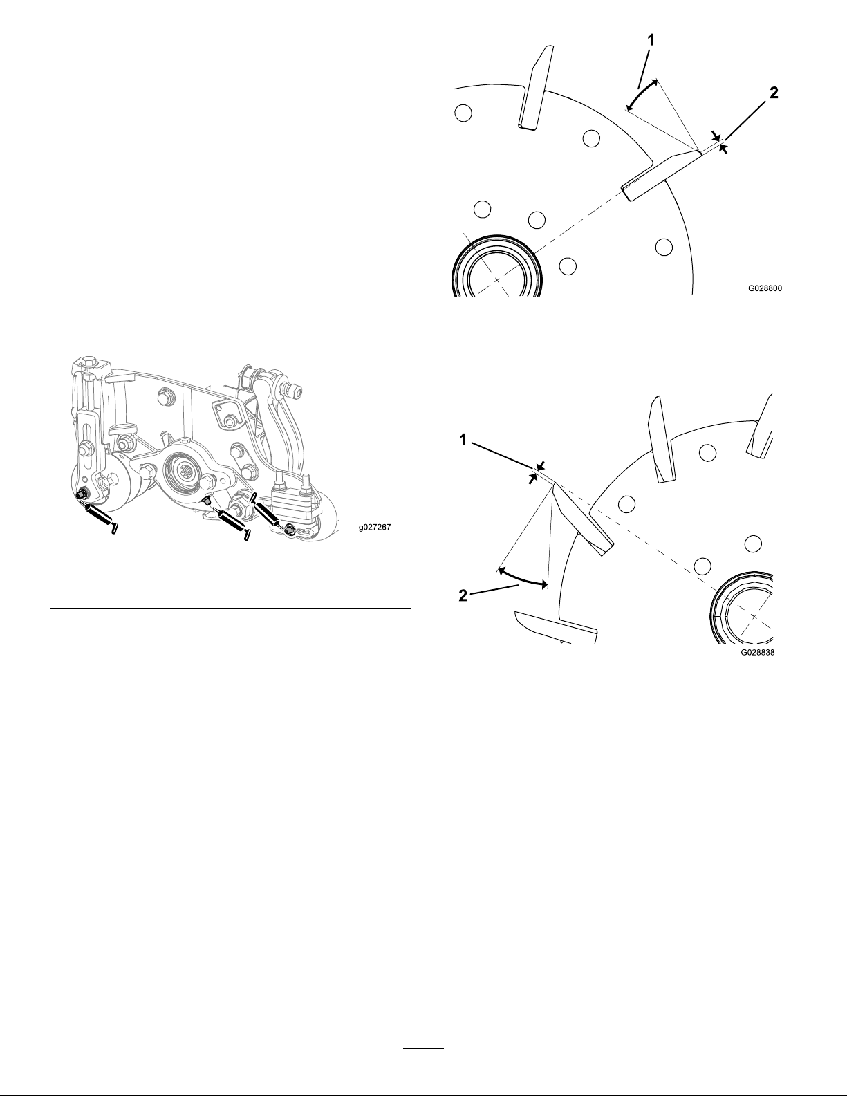
Thereelhasalandwidthof1.3to1.5mm(0.050to0.060
inch)anda30-degreereliefgrind.
Whenthelandwidthgetslargerthan3mm(0.120inch)wide,
dothefollowing:
1.Applya30degreereliefgrindonallreelbladesuntil
thelandwidthis1.3mm(0.050inch)wide(Figure23
andFigure24).
Figure23
Model036321
1.30degrees
Model03623
1.1.3mm(0.050inch)
2.Spingrindthereeltoachieve<0.025mm(0.001inch)
reelrun-out.
Note:Thiscausesthelandwidthtogrowslightly.
2.1.3mm(0.050inch)
Figure24
2.30degrees
Note:Toextendthelongevityofthesharpnessoftheedge
ofthereelandthebedknife—aftergrindingthereeland/or
thebedknife—checkthereel-to-bedknifecontactagainafter
cutting2fairways,asanyburrswillberemoved,whichmay
createimproperreel-to-bedknifeclearanceandthusaccelerate
wear.
14
Page 15
ServicingtheBedknife
2
3
g027268
1
Thebedknifeservicelimitsarelistedinthefollowingchart.
Important:Operatingthecuttingunitwiththebedknifebelowtheservicelimitmayresultinpoorafter-cut
appearanceandreducethestructuralintegrityofthebedknifeforimpacts.
BedknifeServiceLimitChart
Bedknife
LowHOC(Optional)
EdgeMax®LowHOC
(Model03623)
ExtendedLowHOC
(Optional)
ExtendedEdgeMax®
LowHOC(Optional)
EdgeMax®(Model
03621)
Standard(Optional)
HeavyDuty(Optional)
PartNo.
110-40845.6mm
127-71325.6mm
120-16405.6mm
119-42805.6mm
108-90956.9mm
108-90966.9mm
110-40749.3mm
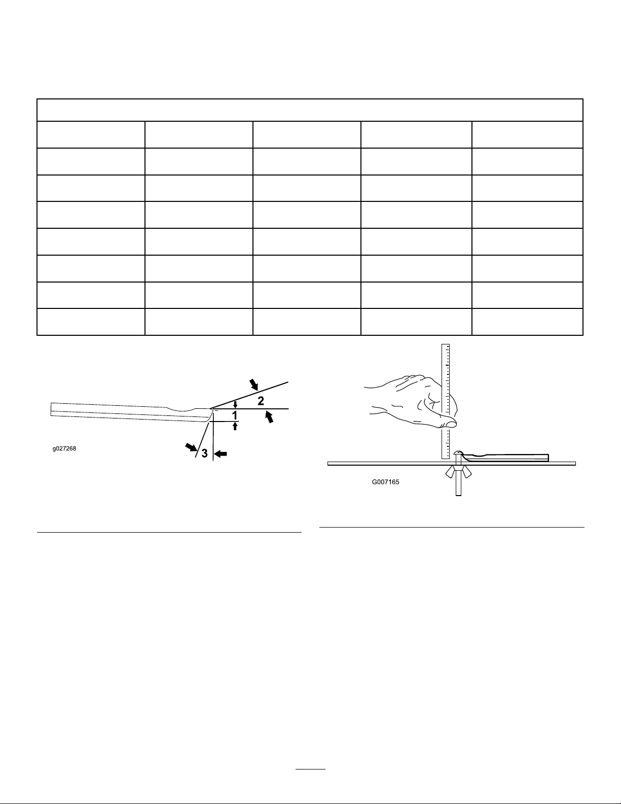
RecommendedT opandFrontBedknifeGrindAngles
(Figure25)
BedknifeLipHeight*ServiceLimit*GrindAngles
(0.220inch)
(0.220inch)
(0.220inch)
(0.220inch)
(0.270inch)
(0.270inch)
(0.370inch)
4.8mm
(0.190inch)
4.8mm
(0.190inch)
4.8mm
(0.190inch)
4.8mm
(0.190inch)
4.8mm
(0.190inch)
4.8mm
(0.190inch)
4.8mm
(0.190inch)
Top/FrontAngles
10/5Degrees
10/5Degrees
10/10Degrees
10/10Degrees
10/5Degrees
10/5Degrees
10/5Degrees
Figure25
1.Bedknifeservicelimit*
2.Topgrindangle
3.Frontgrindangle
Note:Allbedknifeservicelimitmeasurementsreferencethe
bottomofthebedknife(Figure26)
Figure26
CheckingtheTopGrindAngle
Theanglethatyouusetogrindyourbedknivesisvery
important.
Usetheangleindicator(ToroPartNo.131-6828)andthe
angle-indicatormount(ToroPartNo.131-6829)tocheck
theanglethatyourgrinderproducesandthencorrectfor
anygrinderinaccuracy .
1.Placetheangleindicatoronthebottomsideofthe
bedknifeasshowninFigure27.
15
Page 16

Figure27
ServicingtheBedbar
RemovingtheBedbar
1.Turnthebedbar-adjustingscrewscounterclockwiseto
backthebedknifeawayfromthereel(Figure29).
1.Bedknife(vertical)
2.Angleindicator
2.PresstheAltZerobuttonontheangleindicator.
3.Placetheangle-indicatormountontheedgeofthe
bedknifesothattheedgeofthemagnetismatedwith
theedgeofthebedknife(Figure28).
Note:Thedigitaldisplayshouldbevisiblefromthe
samesideduringthisstepasitwasinstep1.
Figure29
1.Bedbar-adjustingscrew3.Bedbar
2.Spring-tensionnut
4.Washer
2.Backoutthespring-tensionnutuntilthewasherisno
longertensionedagainstthebedbar(Figure29).
3.Oneachsideofthemachine,loosenthelocknut
securingthebedbarbolt(Figure30).
Figure28
1.Angle-indicatormount
2.Edgeofthemagnetmated
withtheedgeofthe
bedknife
3.Bedknife
4.Angleindicator
4.Placetheangleindicatoronthemountasshownin
Figure28.
Note:Thisistheanglethatyourgrinderproduces,
andshouldbewithin2degreesoftherecommended
topgrindangle.
Figure30
1.Bedbarbolt2.Locknut
4.Removeeachbedbarbolt,allowingthebedbartobe
pulleddownwardandremovedfromthemachinebolt
(Figure30).
Note:Accountfor2nylonwashersand1stamped
steelwasheroneachendofthebedbar(Figure31).
Figure31
1.Bedbarbolt
2.Nut4.Nylonwasher
3.Steelwasher
16
Page 17

AssemblingtheBedbar
1.Installthebedbar,positioningthemountingears
betweenthewasherandthebedbaradjuster.
2.Securethebedbartoeachsideplatewiththebedbar
bolts(nutsonbolts)andthe6washers.
Note:Positionanylonwasherontheeachsideof
theside-plateboss.Placeasteelwasheroutsideofthe
outernylonwashers(Figure31).
3.Torquethebedbarboltsto27to36N∙m(240to320
in-lb).
4.Tightenthelocknutsequallyoneachsideuntiltheouter
steelwasherscannotberotatedbyhand.Thenloosen
thelocknutsuntiltheoutersteelwashersjustrotateby
hand,yetthereisnobedbarendplay(Figure32).
Note:Overtighteningthelocknutscandeecttheside
platesandthebedbar,whichcanaffectreel-to-bedknife
contact.
Note:Thewashersontheinsidemayhaveagap.
Note:Donotovertightenthenuts,asdamagetothe
springmayoccur.
Threadthebedbar-adjusterscrewintotheadjuster
shaft.
7.Looselyinstallthehardenedwasher,spring,andspring
tensionnutontotheadjusterscrew .
8.Installthebedbar,positioningthemountingears
betweenthewasherandthebedbaradjuster.
9.Securethebedbartoeachsideplatewiththebedbar
bolts(nutsonbolts)and6washersasfollows:
A.Positionanylonwasheroneachsideofthe
side-plateboss.
B.Placeasteelwasheroutsideeachofthenylon
washers(Figure33).
C.Torquethebedbarboltsto37to45N∙m(27to
33ft-lb).
D.Tightenthelocknutsuntiltheoutsidesteelwasher
stopsrotatingandendplayisremoved,butdonot
overtightenordeectthesideplates.
Note:Thewashersontheinsidemayhaveagap
(Figure31).
10.Tightenthenutoneachbedbaradjusterassembly
untilthecompressionspringisfullycompressed,then
loosenthenut1/2turn(Figure32).
Figure32
1.Spring-tensionnut2.Spring
ServicingtheHDDualPoint Adjusters(DPA)
1.Removeallparts;refertoInstallationInstructionsforHD
DPAKitModel120-7230andtoFigure33.
2.Applyanti-seizecompoundtotheinsideofthebushing
areaonthecentercuttingunitframe(Figure33).
3.Alignthekeysontheangebushingstotheslotsinthe
frameandinstallthebushings(Figure33).
4.Installawavewasherontotheadjustershaftandslide
theadjustershaftintotheangebushingsintheframe
ofthecuttingunit(Figure33).
11.Repeattheprocedureontheotherendofthecutting
unit.
12.Adjustthebedknifetothereel.
5.Securetheadjustershaftwithaatwasheranda
locknut(Figure33).Torquethelocknutto20to27
N∙m(15to20ft-lb).
Note:Thebedbar-adjustershafthasleft-handthreads.
6.Applyanti-seizecompoundtothethreadsofthe
bedbar-adjusterscrewthattsintotheadjustershaft.
17
Page 18

1
2
3
4
5
6
7
8
9
10
11
G016355
Figure33
1.Shaftadjuster
2.Wavewasher5.Flatwasher8.Bedbar-adjusterscrew
3.Flangebushing6.Locknut9.Hardenedwasher
4.Applyanti-seizecompound
here.
7.Applyanti-seizecompound
here.
10.Compressionspring
11.Spring-tensionnut
18
Page 19

ServicingtheRoller
ARollerRebuildKit,PartNo.114-5430anda
RollerRebuildT oolKit,PartNo.115-0803(Figure
34)areavailableforservicingtheroller.TheRoller
RebuildKitincludesallthebearings,bearingnuts,
innerseals,andoutersealstorebuildaroller.
TheRollerRebuildToolKitincludesallthetoolsandthe
installationinstructionsrequiredtorebuildarollerwiththe
RollerRebuildKit.RefertoyourPartsCatalogorcontactyour
distributorforassistance.
Figure34
1.Rebuildkit(PartNo.114-5430)
2.Rebuildtoolkit(PartNo.1 15-0803)
3.Innerseal8.Washer
4.Bearing
5.Outerseal
6.Bearingnut
7.Inner-sealtool
9.Bearing/outer-sealtool
19
Page 20

Notes:
20
Page 21

Notes:
21
Page 22

DeclarationofIncorporation
TheT oroCompany,811 1LyndaleAve.South,Bloomington,MN,USAdeclaresthatthefollowingunit(s)
conform(s)tothedirectiveslisted,wheninstalledinaccordancewiththeaccompanyinginstructionsontocertain
ToromodelsasindicatedontherelevantDeclarationsofConformity.
ModelNo.
03621315000001andUp
03623315000001andUp
SerialNo.
ProductDescriptionInvoiceDescription
22-inch8-BladeDPA
CuttingUnitwith5inReel,
Reelmaster3555or5010
SeriesTractionUnit
22-inch11-BladeDPA
CuttingUnitwith5inReel,
Reelmaster3555or5010
SeriesTractionUnit
22IN5IN8-BLD(RR)DP A
CU(5010-H)
22IN5-IN11-BLD(FSR)
DPACU(5010-H)
GeneralDescription
Directive
Cuttingunit2006/42/EC
Cuttingunit2006/42/EC
RelevanttechnicaldocumentationhasbeencompiledasrequiredperPartBofAnnexVIIof2006/42/EC.
Wewillundertaketotransmit,inresponsetorequestsbynationalauthorities,relevantinformationonthispartly
completedmachinery.Themethodoftransmissionshallbeelectronictransmittal.
ThismachineryshallnotbeputintoserviceuntilincorporatedintoapprovedToromodelsasindicatedonthe
associatedDeclarationofConformityandinaccordancewithallinstructions,wherebyitcanbedeclaredin
conformitywithallrelevantDirectives.
Certied:EUTechnicalContact:
MarcVermeiren
ToroEuropeNV
B-2260Oevel-Westerloo
Belgium
DavidKlisTel.003214562960
Sr.EngineeringManager
811 1LyndaleAve.South
Bloomington,MN55420,USA
April25,2016
Fax003214581911
22
Page 23

InternationalDistributorList
Distributor:
AgrolancKft
AsianAmericanIndustrial(AAI)
B-RayCorporation
BrisaGoodsLLC
CascoSalesCompany
CeresS.A.CostaRica
CSSCTurfEquipment(pvt)Ltd.SriLanka
CyrilJohnston&Co.
CyrilJohnston&Co.RepublicofIreland
FatDragon
FemcoS.A.Guatemala
FIVEMANSNew-T echCo.,LtdChina
ForGarderOU
G.Y .K.CompanyLtd.
GeomechanikiofAthensGreece
GolfinternationalTurizm
HakoGroundandGardenSweden
HakoGroundandGarden
HayterLimited(U.K.)
HydroturfInt.CoDubai
HydroturfEgyptLLC
IrrimacPortugal351212388260T oroEuropeNVBelgium3214562960
IrrigationProductsInt'lPvtLtd.India00914424494387ValtechMorocco212537663636
JeanHeybroekb.v.Netherlands31306394611VictusEmakPoland48618238369
Country:
Hungary3627539640
HongKong85224977804
Korea82325512076
Mexico12104952417
PuertoRico7877888383
NorthernIreland442890813121
China
Estonia3723846060
Japan81726325861Riversa
Turkey902163365993
Norway4722907760
UnitedKingdom441279723444
UnitedArabEmirates97143479479T-MarktLogisticsLtd.Hungary3626525500
Egypt2025194308ToroAustraliaAustralia61395807355
PhoneNumber:Distributor:
MaquiverS.A.Colombia
MaruyamaMfg.Co.Inc.
Mountelda.s.CzechRepublic
Mountelda.s.Slovakia
5062391138
94112746100
442890813121ParklandProductsLtd.NewZealand6433493760
8861080841322
5024423277
86-10-63816136
30109350054
4635100000
MunditolS.A.
NormaGarden
OslingerTurfEquipmentSA
OyHakoGroundandGardenAb
Perfetto
PratoverdeSRL.
Prochaska&Cie
RTCohen2004Ltd.
LelyTurfcare
Lely(U.K.)Limited
SolvertS.A.S.
SpyprosStavrinidesLimitedCyprus
SurgeSystemsIndiaLimited
Country:
Japan81332522285
Argentina541 148219999
Russia749541 16120
Ecuador59342396970
Finland35898700733
Poland48618208416
Italy390499128128
Austria4312785100
Israel97298617979
Spain
Denmark4566109200
UnitedKingdom441480226800
France33130817700
India911292299901
PhoneNumber:
5712364079
420255704220
420255704220
34952837500
35722434131
EuropeanPrivacyNotice
TheInformationToroCollects
ToroWarrantyCompany(Toro)respectsyourprivacy.Inordertoprocessyourwarrantyclaimandcontactyouintheeventofaproductrecall,weaskyou
tosharecertainpersonalinformationwithus,eitherdirectlyorthroughyourlocalT orocompanyordealer.
TheT orowarrantysystemishostedonserverslocatedwithintheUnitedStateswhereprivacylawmaynotprovidethesameprotectionasapplies
inyourcountry.
BYSHARINGYOURPERSONALINFORMATIONWITHUS,YOUARECONSENTINGTOTHEPROCESSINGOFYOURPERSONALINFORMATION
ASDESCRIBEDINTHISPRIV ACYNOTICE.
TheWayT oroUsesInformation
Toromayuseyourpersonalinformationtoprocesswarrantyclaims,tocontactyouintheeventofaproductrecallandforanyotherpurposewhichwetell
youabout.ToromayshareyourinformationwithT oro'safliates,dealersorotherbusinesspartnersinconnectionwithanyoftheseactivities.Wewillnot
sellyourpersonalinformationtoanyothercompany.Wereservetherighttodisclosepersonalinformationinordertocomplywithapplicablelawsand
withrequestsbytheappropriateauthorities,tooperateoursystemsproperlyorforourownprotectionorthatofotherusers.
RetentionofyourPersonalInformation
Wewillkeepyourpersonalinformationaslongasweneeditforthepurposesforwhichitwasoriginallycollectedorforotherlegitimatepurposes
(suchasregulatorycompliance),orasrequiredbyapplicablelaw .
Toro'sCommitmenttoSecurityofYourPersonalInformation
Wetakereasonableprecautionsinordertoprotectthesecurityofyourpersonalinformation.Wealsotakestepstomaintaintheaccuracyandcurrent
statusofpersonalinformation.
AccessandCorrectionofyourPersonalInformation
Ifyouwouldliketorevieworcorrectyourpersonalinformation,pleasecontactusbyemailatlegal@toro.com.
AustralianConsumerLaw
AustraliancustomerswillnddetailsrelatingtotheAustralianConsumerLaweitherinsidetheboxoratyourlocalToroDealer.
374-0269RevK
Page 24

TheT oroWarranty
ATwo-YearLimitedWarranty
ConditionsandProductsCovered
TheToroCompanyanditsafliate,T oroWarrantyCompany,pursuant
toanagreementbetweenthem,jointlywarrantyourT oroCommercial
product(“Product”)tobefreefromdefectsinmaterialsorworkmanship
fortwoyearsor1500operationalhours*,whicheveroccursrst.This
warrantyisapplicabletoallproductswiththeexceptionofAerators
(refertoseparatewarrantystatementsfortheseproducts).Wherea
warrantableconditionexists,wewillrepairtheProductatnocosttoyou
includingdiagnostics,labor,parts,andtransportation.Thiswarranty
beginsonthedatetheProductisdeliveredtotheoriginalretailpurchaser .
*Productequippedwithanhourmeter.
InstructionsforObtainingWarrantyService
YouareresponsiblefornotifyingtheCommercialProductsDistributoror
AuthorizedCommercialProductsDealerfromwhomyoupurchasedthe
Productassoonasyoubelieveawarrantableconditionexists.Ifyouneed
helplocatingaCommercialProductsDistributororAuthorizedDealer,or
ifyouhavequestionsregardingyourwarrantyrightsorresponsibilities,
youmaycontactusat:
ToroCommercialProductsServiceDepartment
ToroWarrantyCompany
811 1LyndaleAvenueSouth
Bloomington,MN55420-1196
952–888–8801or800–952–2740
E-mail:commercial.warranty@toro.com
OwnerResponsibilities
AstheProductowner,youareresponsibleforrequiredmaintenanceand
adjustmentsstatedinyourOperator'sManual.Failuretoperformrequired
maintenanceandadjustmentscanbegroundsfordisallowingawarranty
claim.
ItemsandConditionsNotCovered
Notallproductfailuresormalfunctionsthatoccurduringthewarranty
periodaredefectsinmaterialsorworkmanship.Thiswarrantydoesnot
coverthefollowing:
•Productfailureswhichresultfromtheuseofnon-T ororeplacement
parts,orfrominstallationanduseofadd-on,ormodiednon-Toro
brandedaccessoriesandproducts.Aseparatewarrantymaybe
providedbythemanufactureroftheseitems.
•Productfailureswhichresultfromfailuretoperformrecommended
maintenanceand/oradjustments.Failuretoproperlymaintainyour
ToroproductpertheRecommendedMaintenancelistedinthe
Operator’sManualcanresultinclaimsforwarrantybeingdenied.
•ProductfailureswhichresultfromoperatingtheProductinanabusive,
negligent,orrecklessmanner.
•Partssubjecttoconsumptionthroughuseunlessfoundtobedefective.
Examplesofpartswhichareconsumed,orusedup,duringnormal
Productoperationinclude,butarenotlimitedto,brakepadsand
linings,clutchlinings,blades,reels,rollersandbearings(sealedor
greasable),bedknives,sparkplugs,castorwheelsandbearings,tires,
lters,belts,andcertainsprayercomponentssuchasdiaphragms,
nozzles,andcheckvalves,etc.
•Failurescausedbyoutsideinuence.Conditionsconsideredtobe
outsideinuenceinclude,butarenotlimitedto,weather,storage
practices,contamination,useofunapprovedfuels,coolants,lubricants,
additives,fertilizers,water,orchemicals,etc.
•Failureorperformanceissuesduetotheuseoffuels(e.g.gasoline,
diesel,orbiodiesel)thatdonotconformtotheirrespectiveindustry
standards.
•Normalnoise,vibration,wearandtear ,anddeterioration.
•Normal“wearandtear”includes,butisnotlimitedto,damagetoseats
duetowearorabrasion,wornpaintedsurfaces,scratcheddecalsor
windows,etc.
Parts
Partsscheduledforreplacementasrequiredmaintenancearewarranted
fortheperiodoftimeuptothescheduledreplacementtimeforthatpart.
Partsreplacedunderthiswarrantyarecoveredforthedurationofthe
originalproductwarrantyandbecomethepropertyofT oro.T orowillmake
thenaldecisionwhethertorepairanyexistingpartorassemblyorreplace
it.T oromayuseremanufacturedpartsforwarrantyrepairs.
DeepCycleandLithium-IonBatteryWarranty:
DeepcycleandLithium-Ionbatterieshaveaspeciedtotalnumberof
kilowatt-hourstheycandeliverduringtheirlifetime.Operating,recharging,
andmaintenancetechniquescanextendorreducetotalbatterylife.Asthe
batteriesinthisproductareconsumed,theamountofusefulworkbetween
chargingintervalswillslowlydecreaseuntilthebatteryiscompletelyworn
out.Replacementofwornoutbatteries,duetonormalconsumption,
istheresponsibilityoftheproductowner.Batteryreplacementmaybe
requiredduringthenormalproductwarrantyperiodatowner’sexpense.
Note:(Lithium-Ionbatteryonly):ALithium-Ionbatteryhasapartonly
proratedwarrantybeginningyear3throughyear5basedonthetime
inserviceandkilowatthoursused.RefertotheOperator'sManualfor
additionalinformation.
MaintenanceisatOwner’sExpense
Enginetune-up,lubrication,cleaningandpolishing,replacementoflters,
coolant,andcompletingrecommendedmaintenancearesomeofthe
normalservicesT oroproductsrequirethatareattheowner’sexpense.
GeneralConditions
RepairbyanAuthorizedToroDistributororDealerisyoursoleremedy
underthiswarranty.
NeitherTheToroCompanynorToroWarrantyCompanyisliablefor
indirect,incidentalorconsequentialdamagesinconnectionwiththe
useoftheToroProductscoveredbythiswarranty,includingany
costorexpenseofprovidingsubstituteequipmentorserviceduring
reasonableperiodsofmalfunctionornon-usependingcompletion
ofrepairsunderthiswarranty.ExceptfortheEmissionswarranty
referencedbelow,ifapplicable,thereisnootherexpresswarranty.All
impliedwarrantiesofmerchantabilityandtnessforusearelimitedto
thedurationofthisexpresswarranty.
Somestatesdonotallowexclusionsofincidentalorconsequential
damages,orlimitationsonhowlonganimpliedwarrantylasts,sotheabove
exclusionsandlimitationsmaynotapplytoyou.Thiswarrantygivesyou
speciclegalrights,andyoumayalsohaveotherrightswhichvaryfrom
statetostate.
Noteregardingenginewarranty:
TheEmissionsControlSystemonyourProductmaybecoveredby
aseparatewarrantymeetingrequirementsestablishedbytheU.S.
EnvironmentalProtectionAgency(EP A)and/ortheCaliforniaAirResources
Board(CARB).Thehourlimitationssetforthabovedonotapplytothe
EmissionsControlSystemWarranty.RefertotheEngineEmissionControl
WarrantyStatementsuppliedwithyourproductorcontainedintheengine
manufacturer’sdocumentationfordetails
CountriesOtherthantheUnitedStatesorCanada
CustomerswhohavepurchasedT oroproductsexportedfromtheUnitedStatesorCanadashouldcontacttheirT oroDistributor(Dealer)toobtain
guaranteepoliciesforyourcountry ,province,orstate.IfforanyreasonyouaredissatisedwithyourDistributor'sserviceorhavedifcultyobtaining
guaranteeinformation,contacttheT oroimporter.
374-0253RevD
 Loading...