

Page 1
FormNo.3391-854RevA
Reelmaster
®
5410-Gor5510-G
TractionUnit
ModelNo.03608—SerialNo.315000001andUp
ModelNo.03609—SerialNo.315000001andUp
Registeratwww.T oro.com.
OriginalInstructions(EN)
*3391-854*A
Page 2

WARNING
CALIFORNIA
Proposition65Warning
Thisproductcontainsachemicalorchemicals
knowntotheStateofCaliforniatocausecancer,
birthdefects,orreproductiveharm.
Theengineexhaustfromthisproduct
containschemicalsknowntotheStateof
Californiatocausecancer,birthdefects,
orotherreproductiveharm.
Important:Thisengineisnotequippedwithaspark
arrestermufer.ItisaviolationofCaliforniaPublic
ResourceCodeSection4442touseoroperatetheengine
onanyforest-covered,brush-covered,orgrass-covered
land.Otherstatesorfederalareasmayhavesimilarlaws.
Introduction
Thismachineisaride-on,reel-bladelawnmowerintended
tobeusedbyprofessional,hiredoperatorsincommercial
applications.Itisprimarilydesignedforcuttinggrasson
well-maintainedlawnsingolfcourses,parks,sportselds,
andoncommercialgrounds.Itisnotdesignedforcutting
brush,mowinggrassandothergrowthalongsidehighways,
orforagriculturaluses.
Figure1
1.Safetyalertsymbol
Thismanualuses2wordstohighlightinformation.
Importantcallsattentiontospecialmechanicalinformation
andNoteemphasizesgeneralinformationworthyofspecial
attention.
Readthisinformationcarefullytolearnhowtooperateand
maintainyourproductproperlyandtoavoidinjuryand
productdamage.Youareresponsibleforoperatingthe
productproperlyandsafely.
YoumaycontactTorodirectlyatwww .Toro.comforproduct
safetyandoperationtrainingmaterials,accessoryinformation,
helpndingadealer,ortoregisteryourproduct.
Wheneveryouneedservice,genuineT oroparts,oradditional
information,contactanAuthorizedServiceDealerorToro
CustomerServiceandhavethemodelandserialnumbersof
yourproductready.Themodelandserialnumbersareona
platemountedontheleftsideoftheframeunderthefoot
rest.Writethenumbersinthespaceprovided.
ModelNo.
SerialNo.
Thismanualidentiespotentialhazardsandhassafety
messagesidentiedbythesafetyalertsymbol(Figure1),
whichsignalsahazardthatmaycauseseriousinjuryordeath
ifyoudonotfollowtherecommendedprecautions.
©2014—TheToro®Company
8111LyndaleAvenueSouth
Bloomington,MN55420
Contactusatwww.Toro.com.
2
PrintedintheUSA
AllRightsReserved
Page 3

Contents
Safety...........................................................................4
SafeOperatingPractices...........................................4
ToroRidingMowerSafety........................................6
SafetyandInstructionalDecals.................................7
Setup...........................................................................10
1AdjustingtheTirePressure....................................10
2AdjustingtheStepHeight.....................................10
3AdjustingtheControlArmPosition........................11
4InstallingtheCuttingUnits....................................11
5AdjustingtheTurfCompensationSpring.................14
6UsingtheCuttingUnitKickstand...........................15
ProductOverview.........................................................16
Controls...............................................................16
Specications........................................................22
Attachments/Accessories........................................22
Operation....................................................................22
CheckingtheEngine-OilLevel.................................22
CheckingtheCoolingSystem...................................23
AddingFuel...........................................................23
CheckingtheHydraulicFluid...................................24
CheckingtheReeltoBedknifeContact......................26
CheckingtheTorqueoftheWheelNuts.....................26
StartingandStoppingtheEngine..............................26
SettingtheReelSpeed.............................................26
AdjustingtheLiftArmCounterbalance.....................26
AdjustingtheLiftArmTurnAroundPosition.............27
PushingorTowingtheMachine................................27
LocatingtheJackingPoints......................................28
LocatingtheTieDowns..........................................28
UnderstandingtheDiagnosticLight..........................28
CheckingtheInterlockSwitches...............................29
HydraulicValveSolenoidFunctions..........................29
OperatingTips......................................................30
Maintenance.................................................................31
RecommendedMaintenanceSchedule(s)......................31
DailyMaintenanceChecklist....................................32
ServiceIntervalChart.............................................33
Lubrication...............................................................33
GreasingtheBearingsandBushings..........................33
EngineMaintenance..................................................35
ServicingtheAirCleaner.........................................35
ServicingtheEngineOilandFilter............................35
ReplacingtheSparkPlugs........................................36
FuelSystemMaintenance...........................................37
ReplacingtheFuelFilter..........................................37
CheckingtheFuelLinesandConnections..................37
FuelPick-upTubeScreen........................................37
ElectricalSystemMaintenance....................................38
ServicingtheBattery...............................................38
CheckingtheFuses.................................................38
DriveSystemMaintenance.........................................39
AdjustingtheTractionDriveforNeutral....................39
AdjustingtheRearWheelToe-in..............................39
CoolingSystemMaintenance......................................40
RemovingDebrisfromtheCoolingSystem................40
BrakeMaintenance....................................................41
AdjustingtheServiceBrakes....................................41
AdjustingtheParkingBrake....................................41
BeltMaintenance......................................................42
TensioningtheAlternatorBelt.................................42
HydraulicSystemMaintenance....................................42
ChangingtheHydraulicFluid...................................42
ReplacingtheHydraulicFilters.................................43
CheckingtheHydraulicLinesandHoses....................43
UsingtheHydraulicSystemTestPorts.......................44
CuttingUnitSystemMaintenance.................................45
BacklappingtheCuttingUnits..................................45
Storage........................................................................46
PreparingtheTractionUnit.....................................46
PreparingtheEngine..............................................46
3
Page 4

Safety
Improperusingormaintainingthemachinecanresult
ininjury.T oreducethepotentialforinjury,complywith
thesesafetyinstructionsandalwayspayattentiontothe
safetyalertsymbol,whichmeansCaution,Warning,or
Danger—personalsafetyinstruction.Failuretocomply
withtheinstructionmayresultinpersonalinjuryor
death.
SafeOperatingPractices
Training
•Readtheoperator'smanualandothertrainingmaterial
carefully.Befamiliarwiththecontrols,safetysigns,and
theproperuseoftheequipment.
•Neverallowchildrenorpeopleunfamiliarwiththese
instructionstouseorservicethemower.Local
regulationsmayrestricttheageoftheoperator.
•Nevermowwhilepeople,especiallychildren,orpetsare
nearby.
•Donotcarrypassengers.
•Alldriversandmechanicsshouldseekandobtain
professionalandpracticalinstruction.Theowneris
responsiblefortrainingtheusers.Suchinstructionshould
emphasize:
–theneedforcareandconcentrationwhenworking
withride-onmachines;
–controlofaride-onmachineslidingonaslopewill
notberegainedbytheapplicationofthebrake.The
mainreasonsforlossofcontrolare:
◊insufcientwheelgrip;
◊beingdriventoofast;
◊inadequatebraking;
◊thetypeofmachineisunsuitableforitstask;
◊lackofawarenessoftheeffectofground
conditions,especiallyslopes;
◊incorrecthitchingandloaddistribution.
•Theowner/usercanpreventandisresponsiblefor
accidentsorinjuriesoccurringtohimselforherself,other
people,orproperty.
Preparation
•Whilemowing,alwayswearsubstantial,slip-resistant
footwear,longtrousers,hardhat,safetyglasses,andear
protection.Longhair,looseclothing,orjewelrymayget
tangledinmovingparts.Donotoperatetheequipment
whenbarefootorwearingopensandals.
•Thoroughlyinspecttheareawheretheequipmentisto
beusedandremoveallobjectswhichmaybethrownby
themachine.
•Replacefaultysilencers/mufers.
•Evaluatetheterraintodeterminewhataccessoriesand
attachmentsareneededtoproperlyandsafelyperform
thejob.Onlyuseaccessoriesandattachmentsapproved
bythemanufacturer.
•Checkthattheoperator'spresencecontrols,safety
switchesandshieldsareattachedandfunctioning
properly.Donotoperateunlesstheyarefunctioning
properly.
SafeHandlingofFuels
•Toavoidpersonalinjuryorpropertydamage,use
extremecareinhandlinggasoline.Gasolineisextremely
ammableandthevaporsareexplosive.
•Extinguishallcigarettes,cigars,pipes,andothersources
ofignition.
•Useonlyanapprovedfuelcontainer.
•Neverremovefuelcaporaddfuelwiththeengine
running.
•Allowenginetocoolbeforerefueling.
•Neverrefuelthemachineindoors.
•Neverstorethemachineorfuelcontainerwherethereis
anopename,spark,orpilotlightsuchasonawater
heateroronotherappliances.
•Neverllcontainersinsideavehicleoronatruckor
trailerbedwithaplasticliner.Alwaysplacecontainerson
thegroundawayfromyourvehiclebeforelling.
•Removeequipmentfromthetruckortrailerandrefuelit
ontheground.Ifthisisnotpossible,thenrefuelsuch
equipmentwithaportablecontainer,ratherthanfroma
fueldispensernozzle.
•Keepthenozzleincontactwiththerimofthefueltank
orcontaineropeningatalltimesuntilfuelingiscomplete.
Donotuseanozzlelockopendevice.
•Iffuelisspilledonclothing,changeclothingimmediately.
•Neveroverllfueltank.Replacefuelcapandtighten
securely.
Operation
•Donotoperatetheengineinaconnedspacewhere
dangerouscarbonmonoxideandotherexhaustgasses
cancollect.
•Mowonlyindaylightoringoodarticiallight.
•Beforeattemptingtostarttheengine,disengageallblade
attachmentclutches,shiftintoneutral,andengagethe
parkingbrake.
•Rememberthereisnosuchthingasasafeslope.Travel
ongrassslopesrequiresparticularcare.T oguardagainst
overturning:
–Donotstoporstartsuddenlywhengoingupor
downhill.
–Machinespeedsshouldbekeptlowonslopesand
duringtightturns.
4
Page 5

–Stayalertforhumpsandhollowsandotherhidden
hazards.
–Donotturnsharply.Usecarewhenreversing.
–Usecounterweight(s)orwheelweightswhen
suggestedintheoperator'smanual.
•Stayalertforholesintheterrainandotherhiddenhazards.
•Watchoutfortrafcwhencrossingornearroadways.
•Stopthebladesrotatingbeforecrossingsurfacesother
thangrass.
•Whenusinganyattachments,neverdirectdischargeof
materialtowardbystandersnorallowanyonenearthe
machinewhileinoperation.
•Neveroperatethemachinewithdamagedguards,shields,
orwithoutsafetyprotectivedevicesinplace.Besureall
interlocksareattached,adjustedproperly ,andfunctioning
properly.
•Donotchangetheenginegovernorsettingsorover-speed
theengine.Operatingtheengineatexcessivespeedmay
increasethehazardofpersonalinjury.
•Beforeleavingtheoperator'sposition:
–Stoponlevelground.
–Disengagethepowertake-offandlowerthe
attachments.
–Changeintoneutralandsettheparkingbrake.
–Stoptheengineandremovethekey.
•Disengagethedrivestotheattachment(s)when
transportingthemachineornotusingthemachine.
•Stoptheengineanddisengagethedrivestothe
attachment:
–beforerefuelling;
–beforeremovingthegrasscatcher/catchers;
–beforemakingheightadjustmentunlessadjustment
canbemadefromtheoperator'sposition.
–beforeclearingblockages;
–beforechecking,cleaningorworkingonthemower;
–afterstrikingaforeignobjectorifanabnormal
vibrationoccurs.Inspectthemowerfordamage
andmakerepairsbeforerestartingandoperatingthe
equipment.
•Reducetheenginespeedsettingduringenginerun-out
and,iftheengineisprovidedwithashut-offvalve,turn
thefueloffattheconclusionofmowing.
•Keephandsandfeetawayfromthecuttingunits.
•Lookbehindanddownbeforebackinguptobesureof
aclearpath.
•Slowdownandusecautionwhenmakingturnsand
crossingroadsandsidewalks.Stopcylinders/reelsifnot
mowing.
•Donotoperatethemowerundertheinuenceofalcohol
ordrugs.
•Lightningcancausesevereinjuryordeath.Iflightning
isseenorthunderisheardinthearea,donotoperate
themachine;seekshelter.
•Usecarewhenloadingorunloadingthemachineintoa
trailerortruck.
•Usecarewhenapproachingblindcorners,shrubs,trees,
orotherobjectsthatmayobscurevision.
MaintenanceandStorage
•Keepallnuts,boltsandscrewstighttobesurethe
equipmentisinsafeworkingcondition.
•Neverstoretheequipmentwithfuelinthetankinsidea
buildingwherefumesmayreachanopenameorspark.
•Allowtheenginetocoolbeforestoringinanyenclosure.
•Toreducetherehazard,keeptheengine,
silencer/mufer,batterycompartmentandfuelstorage
areafreeofgrass,leaves,orexcessivegrease.
•Checkthegrasscatcherfrequentlyforwearor
deterioration.
•Keepallpartsingoodworkingconditionandallhardware
andhydraulicttingstightened.Replaceallwornor
damagedpartsanddecals.
•Ifthefueltankhastobedrained,dothisoutdoors.
•Becarefulduringadjustmentofthemachinetoprevent
entrapmentofthengersbetweenmovingbladesand
xedpartsofthemachine.
•Onmulti-cylinder/multi-reelmachines,takecareas
rotatingonecylinder/reelcancauseothercylinders/reels
torotate.
•Disengagedrives,lowerthecuttingunits,setparking
brake,stopengineandremovekeyfromignition.Wait
forallmovementtostopbeforeadjusting,cleaning,or
repairingthemachine.
•Cleangrassanddebrisfromcuttingunits,drives,
silencers/mufers,andenginetohelppreventres.Clean
upanyoilorfuelspillage.
•Usejackstandstosupportcomponentswhenrequired.
•Carefullyreleasepressurefromcomponentswithstored
energy.
•Disconnectthebatterybeforemakinganyrepairs.
Disconnectthenegativeterminalrstandthepositive
terminallast.Connectthepositiveterminalrstandthe
negativeterminallast.
•Usecarewhencheckingthecylinders/reels.Weargloves
andusecautionwhenservicingthem.
•Keephandsandfeetawayfrommovingparts.Ifpossible,
donotmakeadjustmentswiththeenginerunning.
•Chargebatteriesinanopen,well-ventilatedarea,away
fromsparksandames.Unplugthechargerbefore
connectingittoordisconnectingitfromthebattery.
Wearprotectiveclothinganduseinsulatedtools.
5
Page 6

ToroRidingMowerSafety
ThefollowinglistcontainssafetyinformationspecictoToro
productsorothersafetyinformationthatyoumustknowthat
isnotincludedintheCEN,ISO,orANSIstandard.
Thisproductiscapableofamputatinghandsandfeetand
throwingobjects.Alwaysfollowallsafetyinstructionsto
avoidseriousinjuryordeath.
Useofthisproductforpurposesotherthanitsintendeduse
couldprovedangeroustouserandbystanders.
WARNING
Engineexhaustcontainscarbonmonoxide,which
isanodorless,deadlypoisonthatcankillyou.
Donotrunengineindoorsorinanenclosedarea.
•Knowhowtostoptheenginequickly.
•Donotoperatethemachinewhilewearingtennisshoes
orsneakers.
•Wearingsafetyshoesandlongpantsisadvisableand
requiredbysomelocalordinancesandinsurance
regulations.
•Handlefuelcarefully.Wipeupanyspills.
•Checkthesafetyinterlockswitchesdailyforproper
operation.Ifaswitchshouldfail,replacetheswitch
beforeoperatingthemachine.
•Beforestartingtheengine,sitontheseat.
•Usingthemachinedemandsattention.Topreventloss
ofcontrol:
–Donotdriveclosetosandtraps,ditches,creeks,or
otherhazards.
–Reducespeedwhenmakingsharpturns.Avoid
suddenstopsandstarts.
withterrainangles,ricochets,orimproperlypositioned
guardscanleadtothrownobjectinjuries.Donotresume
mowinguntiltheareaiscleared.
MaintenanceandStorage
•Makesureallhydrauliclineconnectorsaretightandall
hydraulichosesandlinesareingoodconditionbefore
applyingpressuretothesystem.
•Keepyourbodyandhandsawayfrompinholeleaksor
nozzlesthatejecthydraulicuidunderhighpressure.
Usepaperorcardboard,notyourhands,tosearchfor
leaks.Hydraulicuidescapingunderpressurecanhave
sufcientforcetopenetratetheskinandcauseserious
injury.Seekimmediatemedicalattentionifuidis
injectedintoskin.
•Beforedisconnectingorperforminganyworkonthe
hydraulicsystem,allpressureinthesystemmustbe
relievedbystoppingtheengineandloweringthecutting
unitsandattachmentstotheground.
•Checkallfuellinesfortightnessandwearonaregular
basis.Tightenorrepairthemasneeded.
•Iftheenginemustberunningtoperformamaintenance
adjustment,keephands,feet,clothing,andanypartsof
thebodyawayfromthecuttingunits,attachments,and
anymovingparts.Keepeveryoneaway.
•Toensuresafetyandaccuracy,haveanAuthorizedToro
Distributorcheckthemaximumenginespeedwitha
tachometer.
•Ifmajorrepairsareeverneededorifassistanceisdesired,
contactanAuthorizedToroDistributor.
•Toensureoptimumperformanceandcontinuedsafety
certicationofthemachine,useonlygenuineToro
replacementpartsandaccessories.Replacementparts
andaccessoriesmadebyothermanufacturerscouldbe
dangerous,andsuchusecouldvoidtheproductwarranty.
–Whennearorcrossingroads,alwaysyieldthe
right-of-way.
–Applytheservicebrakeswhengoingdownhillto
keepforwardspeedslowandtomaintaincontrolof
themachine.
•Raisethecuttingunitswhendrivingfromoneworkarea
toanother.
•Donottouchtheengine,silencer/mufer,orexhaust
pipewhiletheengineisrunningorsoonafterithas
stoppedbecausetheseareascouldbehotenoughtocause
burns.
•Iftheenginestallsorlosesheadwayandcannotmakeit
tothetopofaslope,donotturnthemachinearound.
Alwaysbackslowly,straightdowntheslope.
•Whenapersonorpetappearsunexpectedlyinornearthe
mowingarea,stopmowing.Carelessoperation,combined
Hauling
•Usecarewhenloadingorunloadingthemachineintoa
trailerortruck.
•Usefullwidthrampsforloadingmachineintotraileror
truck.
•Tiethemachinedownsecurelyusingstraps,chains,cable,
orropes.Bothfrontandrearstrapsshouldbedirected
downandoutwardfromthemachine.
6
Page 7
SafetyandInstructionalDecals
Safetydecalsandinstructionsareeasilyvisibletotheoperatorandarelocatednearanyareaofpotential
danger.Replaceanydecalthatisdamagedorlost.
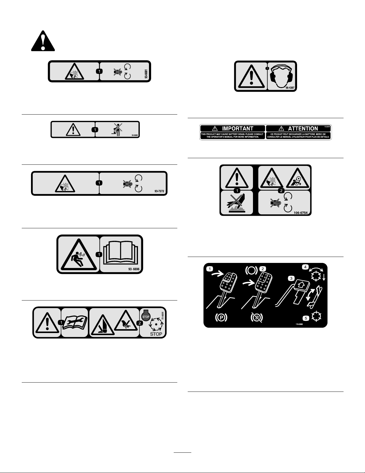
93-6681
1.Cutting/dismemberment—hazard,fan-stayawayfrom
movingparts.
98-4387
1.Warning—wearhearingprotection.
93–6689
1.Danger—noriders.
93-7272
1.Cutting/dismemberment—hazard,fan-stayawayfrom
movingparts.
93–6696
1.Storedenergyhazard—readtheOperator'sManual.
112-5019
106-6754
1.Warning—donottouchthehotsurface.
2.Cutting/dismembermenthazard,fanandentanglement
hazard,belt—stayawayfrommovingparts.
1.Warning—readthe
instructionsbefore
servicingorperforming
maintenance.
93-6688
2.Cuttinghazardofhandor
foot—stoptheengineand
waitformovingpartsto
stop.
110-0986
1.Pressthebrakepedalandparkingbrakepedaltosetthe
parkingbrake.
2.Pressthebrakepedaltoapplythebrake.
3.Pressthetractionpedaltomovethemachineforward.
4.Reelenabledmode
5.Transportmode
7
Page 8
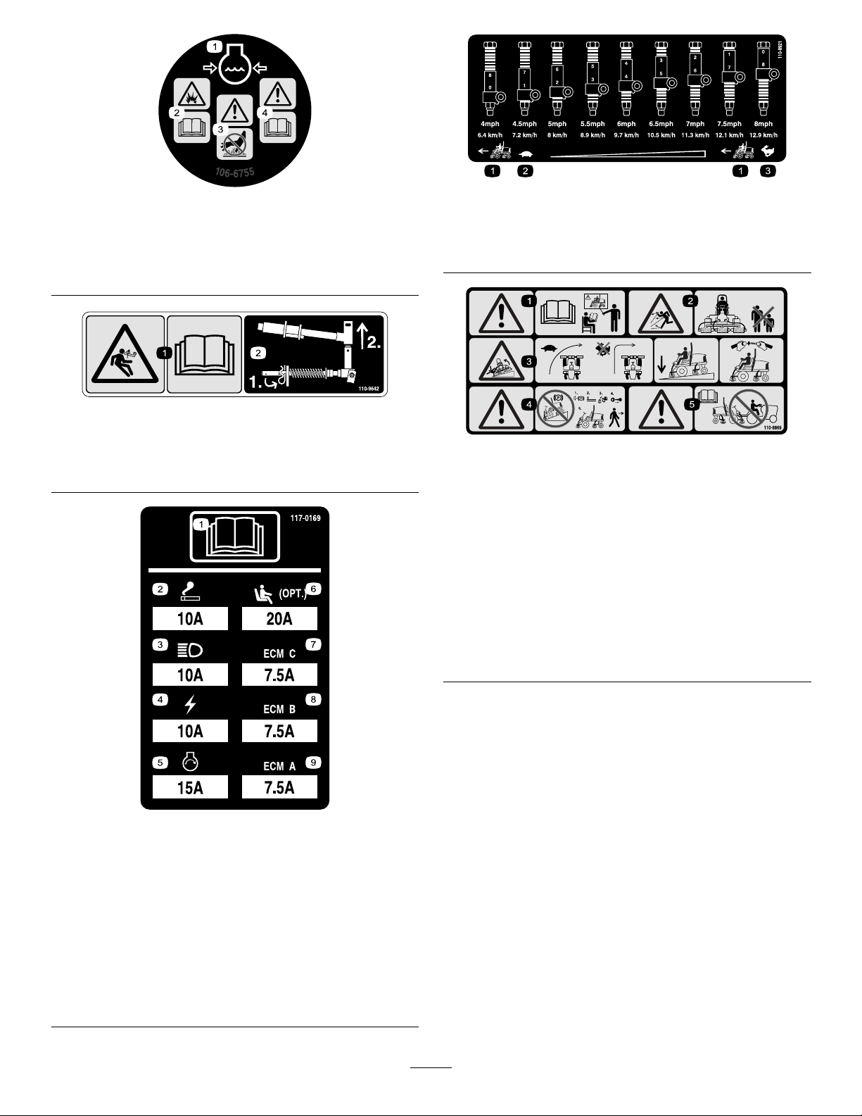
1.Enginecoolantunder
pressure.
2.Explosionhazard—read
theOperator'sManual.
106-6755
3.Warning—donottouchthe
hotsurface.
4.Warning—readthe
Operator'sManual.
110-9642
110-8921
1.Tractionunitspeed
2.Slow
3.Fast
1.Storedenergyhazard—readtheOperator'sManual.
2.Movethecotterpintotheholeclosesttotherodbracket
andthenremovetheliftarmandpivotyoke.
117–0169
110-8869
1.Warning—readtheOperator'sManual,donotoperatethis
machineunlessyouaretrained.
2.Thrownobjecthazard—keepbystandersasafedistance
fromthemachine.
3.Tippinghazard—slowmachinebeforeturning,donotturn
athighspeeds;lowerthecuttingunitwhendrivingdown
slopes;usearolloverprotectionsystemandweartheseat
belt.AlwayswearaseatbeltwhenaROPSisinplace.
4.Warning—donotparkthemachineonslopes;engagethe
parkingbrake,lowerthecuttingdecks,stoptheengineand
removetheignitionkeybeforeleavingthemachine.
5.Warning—readtheOperator'sManual,donottowthe
machine.
1.ReadtheOperator'sManual.
2.Powerpoint—10amp
3.Headlights—10amp
4.Power—10amp
5.Enginestart—15amp
6.Optionalairrideseatsuspension—20amp
7.EnginecomputermanagementC—7.5amp
8.EnginecomputermanagementB—7.5amp
9.EnginecomputermanagementA—7.5amp
8
Page 9
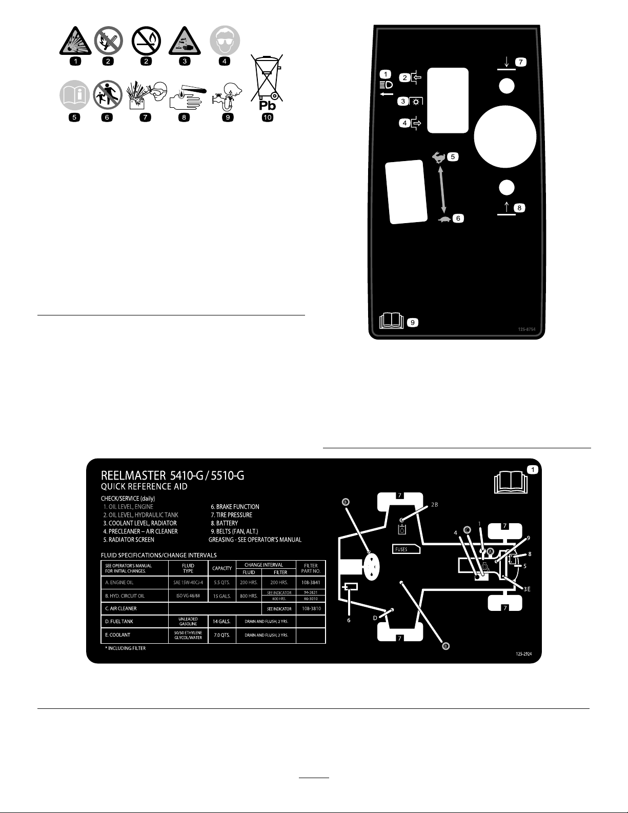
BatterySymbols
Someorallofthesesymbolsareonyourbattery
1.Explosionhazard
2.Nore,opename,or
smoking.
3.Causticliquid/chemical
burnhazard
4.Weareyeprotection9.Flusheyesimmediately
5.ReadtheOperator's
Manual.
6.Keepbystandersasafe
7.Weareyeprotection;
8.Batteryacidcancause
10.Containslead;donot
distancefromthebattery.
explosivegasescan
causeblindnessandother
injuries
blindnessorsevereburns.
withwaterandgetmedical
helpfast.
discard.
125–8754
1.Headlights
2.Engage7.Lowerthecuttingunits
3.Powertake-off(PTO)
4.Disengage
5.Fast
6.Slow
8.Raisethecuttingunits
9.ReadtheOperator’s
Manual.
1.ReadtheOperator’sManual.
125–2924
9
Page 10

Setup
LooseParts
Usethechartbelowtoverifythatallpartshavebeenshipped.
ProcedureDescription
1
2
3
4
5
6
Nopartsrequired
Nopartsrequired
Nopartsrequired
Fronthoseguide(right-hand)
Fronthoseguide(left-hand)
Nopartsrequired
Cuttingunitkickstand
MediaandAdditionalParts
Description
Operator'sManual
Engineoperator’smanual1
PartsCatalog
Qty.
Qty.
–
–
–
1
1
–
1
1
1
Readthemanualsbeforeoperatingthemachineanduse
themtoreferenceinformationaboutthemachine.
UsethePartsCatalogtoreferencepartnumbers.
Adjustthetirepressure.
Adjustthestepheight.
Adjustthecontrolarmposition.
Installthecuttingunits.
Adjusttheturfcompensationspring.
InstalltheCuttingUnitKickstand.
Use
Use
Operatortrainingmaterial
CuttingPerformancePaper
Shim
Note:Determinetheleftandrightsidesofthemachine
fromthenormaloperatingposition.
1
AdjustingtheTirePressure
NoPartsRequired
Procedure
Thetiresareover-inatedforshipping.Therefore,release
someoftheairtoreducethepressure.Correctairpressurein
thefrontandreartiresis83to103kPa(12to15psi).
1
1
1
Reviewthetrainingmaterialbeforeoperatingthemachine.
Usethepaperforadjustingthecuttingunitbedknifeto
reelcontact.
Usetheshimforadjustingthecuttingunitbedknifetoreel
contact.
2
AdjustingtheStepHeight
NoPartsRequired
Procedure
Theheightofthestepscanbeadjustedfortheoperators
comfort.
1.Removethe2boltsandnutssecuringthestepbrackets
tothetractionunitframe(Figure2).
Important:Maintainevenpressureinalltirestoensure
uniformcontactwiththeturf.
10
Page 11
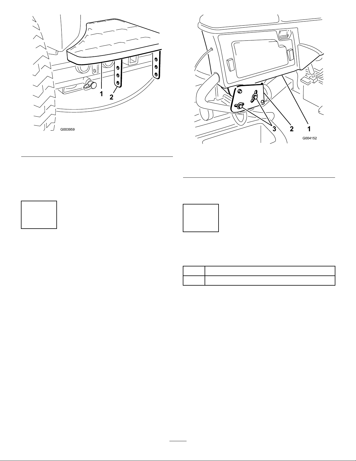
Figure2
1.Step2.Stepbrackets
2.Raiseorlowerthesteptothedesiredheightand
re-securethebracketstotheframewiththe2bolts
andnuts.
3.Repeattheprocedureontheotherstep.
3
AdjustingtheControlArm Position
NoPartsRequired
Procedure
Thecontrolarmpositioncanbeadjustedfortheoperator’s
comfort.
1.Loosenthe2boltssecuringthecontrolarmtothe
retainingbracket(Figure3).
Figure3
1.Controlarm3.Bolts(2)
2.Retainingbrackets
2.Rotatethecontrolarmtothedesiredpositionand
tightenthe2bolts.
4
InstallingtheCuttingUnits
Partsneededforthisprocedure:
1
Fronthoseguide(right-hand)
1
Fronthoseguide(left-hand)
Procedure
1.Removethereelmotorsfromtheshippingbrackets.
2.Removetheshippingbracketsanddiscard.
3.Removethecuttingunitsfromthecartons.Assemble
andadjustthemasdescribedinthecuttingunit
Operator'sManual.
4.Makesurethecounterweight(Figure4)isinstalledto
theproperendofthecuttingunitasdescribedinthe
cuttingunitOperator'sManual.
11
Page 12
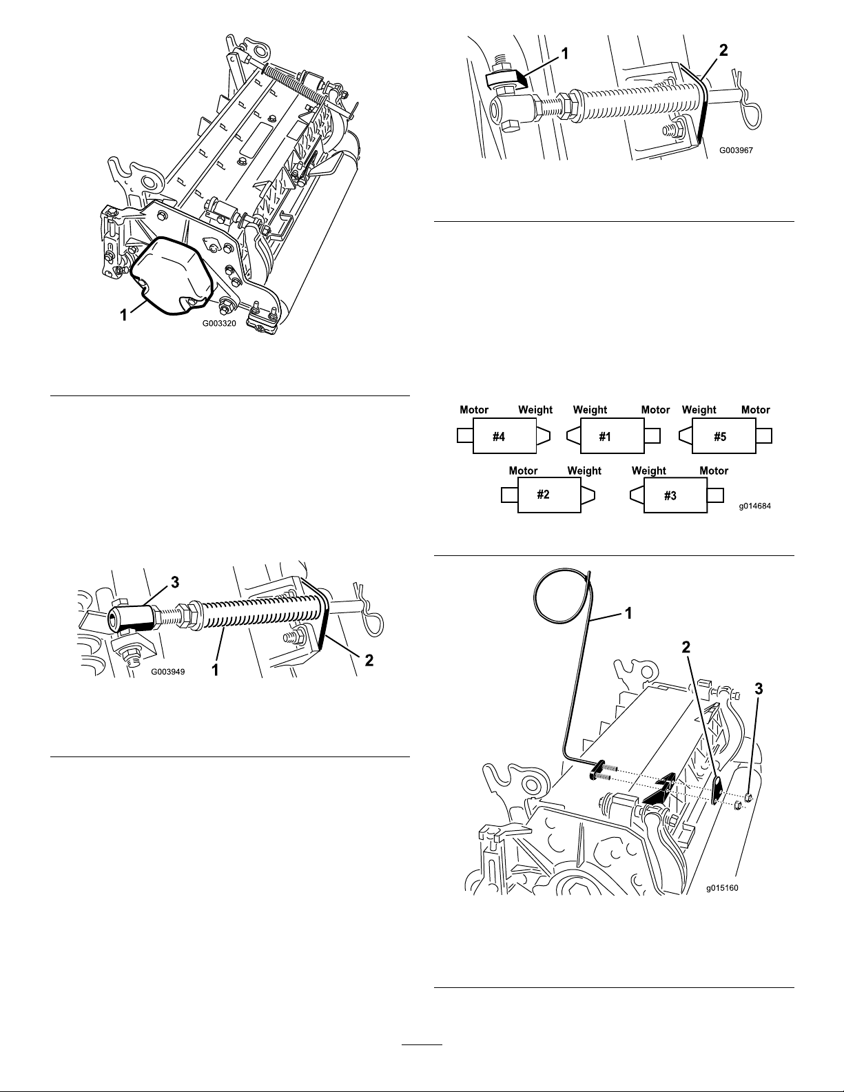
Figure6
Figure4
1.Counterweight
5.Allthecuttingunitsareshippedwiththeturf
compensationspringmountedtotherightsideofthe
cuttingunit.Theturfcompensationspringmustbe
mountedtothesamesideofthecuttingunitasthe
reeldrivemotor.Repositiontheturfcompensation
asfollows:
A.Removethe2carriageboltsandnutssecuringthe
rodbrackettothecuttingunittabs(Figure5).
1.Oppositecarrierframetab
2.Rodbracket
D.Mounttherodbrackettothecuttingunittabs
withthecarriageboltsandnuts(Figure6).
Important:Onthe#4(leftfront)and#5
(rightfront)cuttingunits(Figure7),use
therodbracketmountingnutstoinstallthe
hoseguidestothefrontofthecuttingunit
tabs(Figure8).Thehoseguidesshouldlean
towardthecentercuttingunit(Figure8and
Figure9).
Figure7
Figure5
1.Turfcompensationspring3.Springtube
2.Rodbracket
B.Removetheangenutsecuringthespringtube
bolttothecarrierframetab(Figure5)Remove
theassembly.
C.Mountthespringtubebolttotheoppositetabon
thecarrierframeandsecurewiththeangenut.
Theboltheadistobepositionedtotheouterside
ofthetabasshowninFigure6.
1.Hoseguide(#4cuttingunit
shown)
2.Rodbracket
12
Figure8
3.Nuts
Page 13
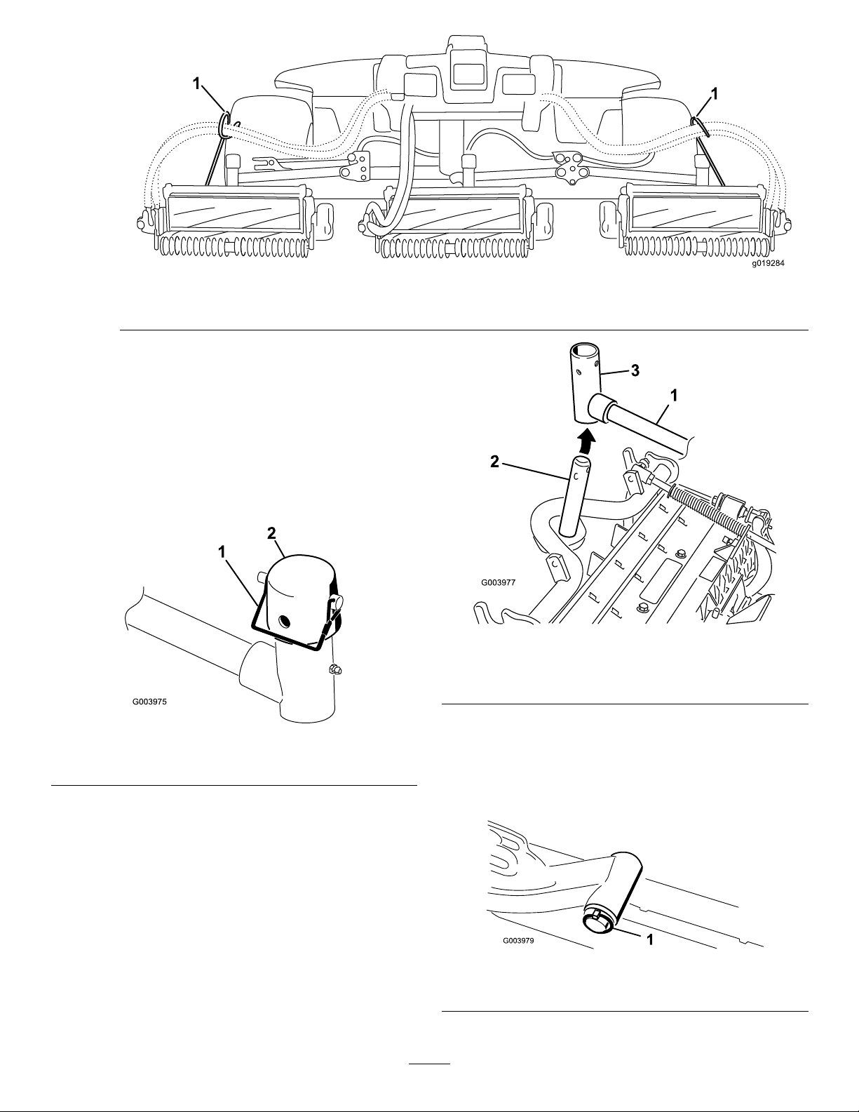
g019284
1
1
1.Hoseguides(eachmustleantowardthecentercuttingunit)
Note:Wheninstallingorremovingthecutting
units,makesurethehairpincotterisinstalledin
thespringrodholenexttotherodbracket.When
notinstallingorremovingthecuttingunits,the
hairpincottermustbeinstalledintheholeinthe
endoftherod.
6.Loweralltheliftarmscompletely.
7.Removethesnapperpinandthecapfromtheliftarm
pivotyoke(Figure10).
Figure9
Figure11
1.Liftarm3.Liftarmpivotyoke
2.Carrierframeshaft
Figure10
1.Snapperpin2.Cap
8.Forthefrontcuttingunits,slideacuttingunitunder
theliftarmwhileinsertingthecarrierframeshaftup
intotheliftarmpivotyoke(Figure11).
9.Usethefollowingprocedureontherearcuttingunits
whentheheightofcutisabove19.5mm(3/4inch).
A.Removethelynchpinandwashersecuringthelift
armpivotshafttotheliftarmandslidethelift
armpivotshaftoutoftheliftarm(Figure12).
Figure12
1.Liftarmpivotshaftlynchpinandwasher
13
Page 14
B.Inserttheliftarmyokeontothecarrierframe
shaft(Figure11).
C.Inserttheliftarmshaftintotheliftarmandsecure
itwiththewasherandlynchpin(Figure12).
10.Insertthecapoverthecarrierframeshaftandliftarm
yoke.
11.Securethecapandthecarrierframeshafttothelift
armyokewiththesnapperpin.Usetheslotifasteering
cuttingunitisdesiredorusetheholeifthecuttingunit
istobelockedinposition(Figure10).
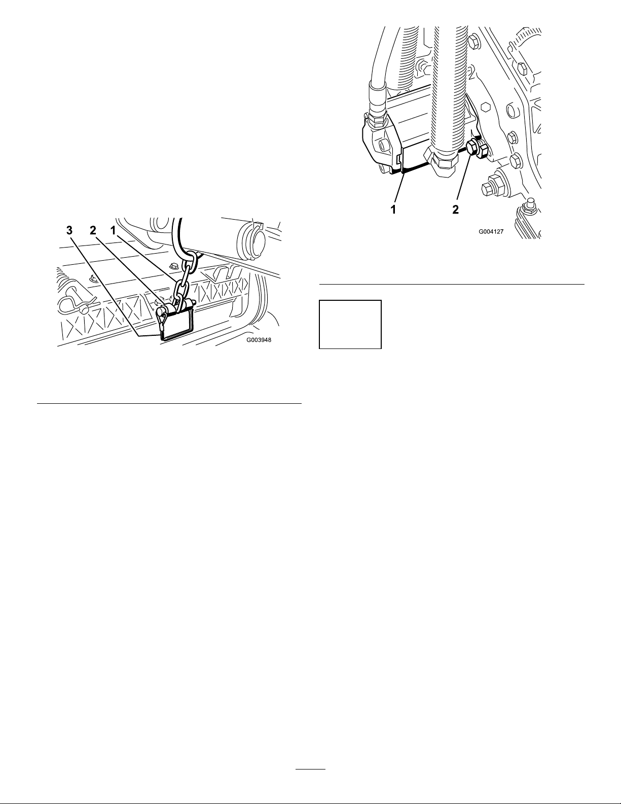
12.Securetheliftarmchaintothechainbracketwiththe
snapperpin(Figure13).Usethenumberofchainlinks
describedinthecuttingunitOperator'sManual.
Figure14
1.Reeldrivemotor2.Mountingbolts
Figure13
1.Liftarmchain3.Snapperpin
2.Chainbracket
13.Onthe#4(leftfront)and#5(rightfront)cutting
units,insertthereelmotorhosesintotherespective
hoseguide.
14.Coatthesplineshaftofthereelmotorwithclean
grease.
15.OilthereelmotorO-ringandinstallitontothemotor
ange.
16.Installthemotorbyrotatingitclockwisesothatthe
motorangesclearthebolts(Figure14).Rotatethe
motorcounterclockwiseuntiltheangesencirclethe
boltsthentightenthebolts.
Important:Makesurethereelmotorhosesare
nottwisted,kinkedorintheriskofbeingpinched.
5
AdjustingtheTurf CompensationSpring
NoPartsRequired
Procedure
Theturfcompensationspring(Figure15)transfersweight
fromthefronttotherearroller.Thishelpstoreduceawave
patternintheturf,alsoknownasmarcellingorbobbing.
Important:Makespringadjustmentswiththecutting
unitmountedtothetractionunit,pointingstraight
ahead,andloweredtotheshopoor.
1.Makesurethatthehairpincotterisinstalledintherear
holeinthespringrod(Figure15).
14
Page 15
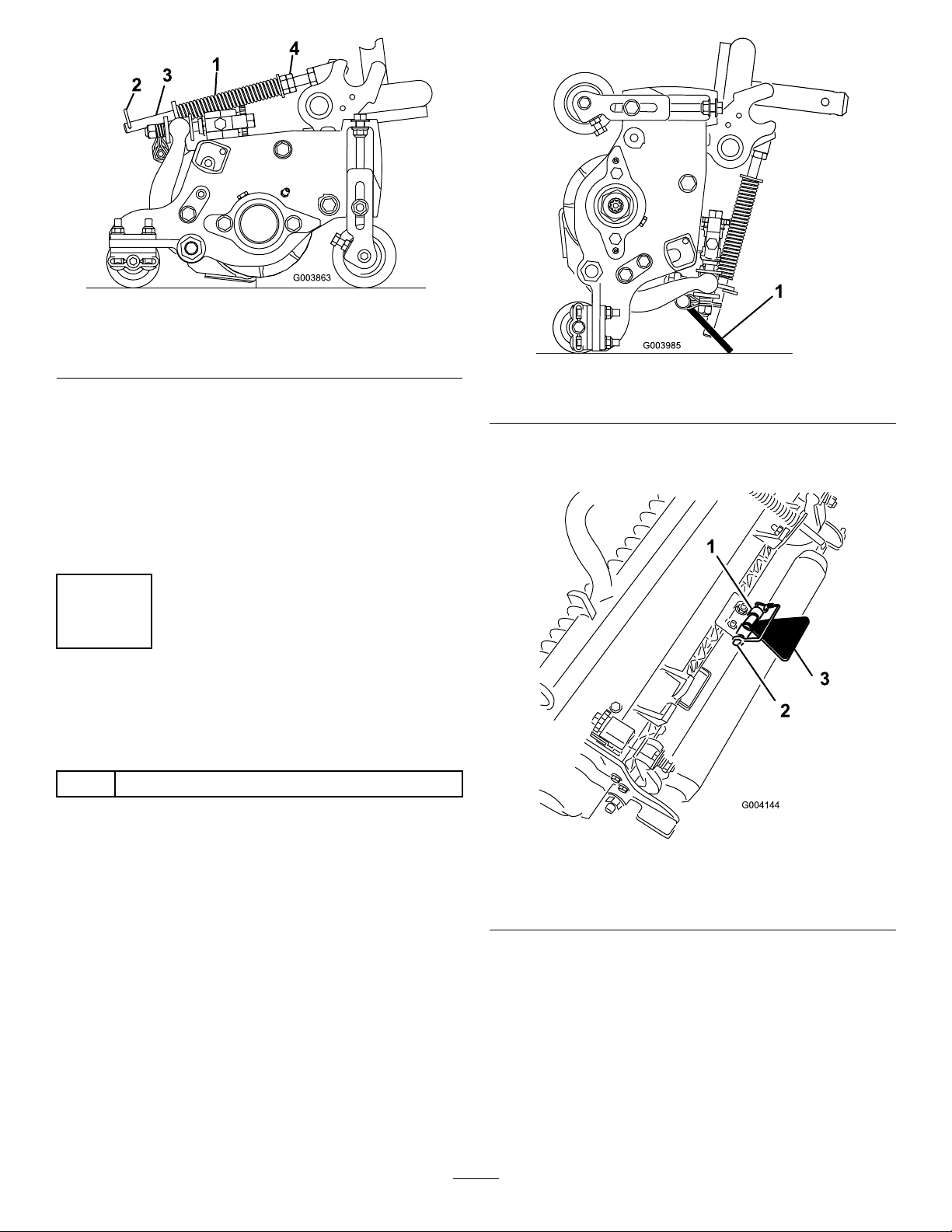
Figure15
1.Turfcompensationspring3.Springrod
2.Hairpincotter4.Hexnuts
Figure16
2.Tightenthehexnutsonthefrontendofthespring
roduntilthecompressedlengthofthespringis12.7
cm(5inches)onReelmaster5410,5inchcuttingunits
or15.9cm(6.25inches)onReelmaster5510,7inch
cuttingunits(Figure15).
Note:Whenoperatingonroughterraindecrease
thespringlengthby12.7mm(1/2inch);thisslightly
decreasesgroundfollowing.
6
UsingtheCuttingUnit Kickstand
Partsneededforthisprocedure:
1
Cuttingunitkickstand
Procedure
Wheneverthecuttingunithastobetippedtoexposethe
bedknife/reel,propuptherearofthecuttingunitwiththe
kickstandtomakesurethenutsonthebackendofthe
bedbaradjustingscrewsarenotrestingontheworksurface
(Figure16).
1.Cuttingunitkickstand
Securethekickstandtothechainbracketwiththesnapper
pin(Figure17).
Figure17
1.Chainbracket3.Cuttingunitkickstand
2.Snapperpin
15
Page 16

ProductOverview
Figure18
howfaryoupressthepedal.Fornoload,maximumground
speed,fullypressthepedalwhiletheenginespeedsetting
isintheFastposition.
Tostop,reducefootpressureonthetractionpedalandallow
ittoreturntothecenterposition.
1.Enginehood
2.Operator'sseat
3.Controlarm
4.Steeringwheel
5.Seatadjustingcontrols
6.Frontcuttingunits
7.Rearcuttingunits
Controls
SeatAdjustingControls
Theseatadjustinglever(Figure19)allowsyoutoadjustthe
seatforeandaft.Theweightadjustingknobadjuststheseat
fortheoperator'sweight.Theweightgaugeindicateswhen
theseatisadjustedtotheweightoftheoperator.Theheight
adjustingknobadjuststheseatfortheoperator'sheight.
Figure20
1.Tractionpedal4.Brakepedal
2.Mowspeedlimiter5.Parkingbrake
3.Spacers
6.Tiltsteeringpedal
MowSpeedLimiter
Whenthemowspeedlimiter(Figure20)isippedupit
controlsthemowspeedandallowsthecuttingunitstobe
engaged.Eachspaceradjuststhemowingspeedby0.8km/h
(1/2mph).Themorespacersyouhaveonthetopofthe
bolt,theslowerthemachinegoes.Fortransport,ipbackthe
mowspeedlimitertohavemaximumtransportspeed.
BrakePedal
Pressthebrakepedal(Figure20)tostopthemachine.
ParkingBrake
Figure19
1.Weightgauge3.Heightadjustingknob
2.Weightadjustingknob
4.Adjustinglever(foreand
aft)
TractionPedal
Thetractionpedal(Figure20)controlstheforwardand
reverseoperation.Pressthetopofthepedaltomoveforward
andthebottomtomoverearward.Groundspeeddependson
Toengagetheparkingbrake,(Figure20)pushdownonthe
brakepedalandpressthetopforwardtolatchit.Torelease
theparkingbrake,pressthebrakepedaluntiltheparking
brakelatchretracts.
TiltSteeringPedal
Totiltthesteeringwheeltowardsyou,pressthefootpedal
(Figure20)down,andpullthesteeringtowertowardyouto
themostcomfortablepositionandthenreleasethepedal.
EngineSpeedSwitch
Theenginespeedswitch(Figure21)has2modestochange
theenginespeed.Bymomentarilytappingtheswitch,youcan
16
Page 17

increaseordecreasetheenginespeedin100-rpmincrements.
1
2
3
4
5
6
G021208
1
g021209
Byholdingtheswitchdown,theenginespeedautomatically
movestoHighorLowidle,dependingonwhichendofthe
switchyoupress.
Figure21
1.Lowermow/raisecontrol
lever
2.Keyswitch5.Enginespeedswitch
3.InfoCenter
4.Enable/disableswitch
6.Headlightswitch
Enable/DisableSwitch
Usetheenable/disableswitch(Figure21)inconjunctionwith
thelowermow/raisecontrollevertooperatethecutterheads.
InfoCenter
TheInfoCenterLCDdisplayshowsinformationaboutyour
machinesuchastheoperatingstatus,variousdiagnosticsand
otherinformationaboutthemachine(Figure21).
KeySwitch
Thekeyswitch(Figure21)has3positions:Off,On/Run,
andStart.
LowerMow/RaiseControlLever
Figure22
1.Backlaplevers
HydraulicFilterRestrictionIndicator
Withtheenginerunningatnormaloperatingtemperature,
viewtheindicator(Figure23),itshouldbeintheGreenzone.
WhentheindicatorisintheRedzone,changethehydraulic
lters.
Thislever(Figure21)raisesandlowersthecuttingunitsand
alsostartsandstopsthecutterheadswhenthecutterheads
areenabledinthemowmode.Thecutterheadscannotbe
loweredwhenthemow/transportleverisinthetransport
position.
1.Hydrauliclterrestrictionindicator
Figure23
PowerPoint
HeadlightSwitch
Pivottheswitchdownwardtoturnontheheadlights(Figure
21).
Thepowerpointisa12voltpowersupplyforelectronic
devices(Figure24).
BacklapLevers
Usethebacklapleversinconjunctionwiththelower
mow/raisecontrolleverforbacklappingthereels(Figure22).
17
Page 18

1
g020650
2
3
4
TORO
InfoCenterIconDescription
Figure24
1.Powerpoint
UsingtheInfoCenterLCDDisplay
TheInfoCenterLCDdisplayshowsinformationaboutyour
machinesuchastheoperatingstatus,variousdiagnostics
andotherinformationaboutthemachine(Figure25)There
isasplashscreenandmaininformationscreenofthe
InfoCenter.Youcanswitchbetweenthesplashscreenand
maininformationscreen,atanytime,bypressinganyof
theInfoCenterbuttonsandthenselectingtheappropriate
directionalarrow .
SERVICEDUE
Indicateswhenscheduledservice
shouldbeperformed
Enginerpm/status—indicatesthe
enginespeed
Hourmeter
Infoicon
Fast
Slow
Fuellevel
Stationaryregenerationrequired
Glowplugsareactive
Raisecuttingunits
Lowercuttingunits
Operatormustsitinseat
ParkingBrakeIndicator—indicates
whentheparkingbrakeisOn
IdentiestherangeasHigh
(Transport)
Neutral
IdentiestherangeasLow(Mow)
Figure25
1.Indicatorlight3.Middlebutton
2.Rightbutton
4.Leftbutton
•LeftButton,MenuAccess/BackButton—pressthis
buttontoaccesstheInfoCentermenus.Youcanuseitto
CoolantTemperature-indicatesthe
enginecoolanttemperatureineither
°Cor°F
Temperature(hot)
PTOisengaged
backoutofanymenuyouarecurrentlyusing.
•MiddleButton—usethisbuttontoscrolldownmenus.
•RightButton—usethisbuttontoopenamenuwherea
rightarrowindicatesadditionalcontent.
Note:Thepurposeofeachbuttonmaychangedepending
onwhatisrequiredatthetime.Eachbuttonwillbelabeled
Deniedornotallowed
EngineStart
Stoporshutdown
withanicondisplayingitscurrentfunction.
18
Page 19

InfoCenterIconDescription(cont'd.)
Symbolsareoften
combinedtoform
sentences.Some
examplesareshown
below
Engine
Keyswitch
Indicateswhenthecuttingunitsare
beinglowered
Indicateswhenthecuttingunitsare
beingraised
PINpasscode
CANbus
InfoCenter
Badorfailed
Bulb
OutputofTECcontrollerorcontrol
wireinharness
Switch
Operatormustreleaseswitch
Operatorshouldchangetoindicated
state
Operatorshouldputmachinein
neutral
Enginestartdenied
Engineshutdown
Enginecoolanttoohot
Sitdownorsetparkingbrake
UsingtheMenus
ToaccesstheInfoCentermenusystem,pressthemenuaccess
buttonwhileatthemainscreen.Thisbringsyoutothemain
menu.Refertothefollowingtablesforasynopsisofthe
optionsavailablefromthemenus:
MainMenu
MenuItemDescription
FaultsTheFaultsmenucontains
ServiceTheServicemenucontains
DiagnosticsTheDiagnosticsmenu
SettingsTheSettingsmenuallows
AboutTheAboutmenuliststhe
Service
MenuItemDescription
Hours
Counts
Diagnostics
MenuItemDescription
CuttingUnitsIndicatestheinputs,qualiers
Hi/LowRangeIndicatestheinputs,qualiers
PTOIndicatestheinputs,qualiers
alistoftherecentmachine
faults.RefertotheService
ManualoryourAuthorized
ToroDistributorformore
informationontheFaults
menuandtheinformation
containedthere.
informationonthemachine
suchashoursofusecounters
andothersimilarnumbers.
displaysthestateofeach
machineswitch,sensorand
controloutput.Y oucanuse
thistotroubleshootcertain
issuesasitquicklytellsyou
whichmachinecontrolsareon
andwhichareoff.
youtocustomizeandmodify
congurationvariablesonthe
InfoCenterdisplay.
modelnumber,serialnumber,
andsoftwareversionofyour
machine.
Liststhetotalnumberofhours
thatthemachine,engineand
PTOhavebeenon,aswell
asthenumberofhoursthe
machinehasbeentransported
andservicedue.
Listsnumerouscountsthe
machinehasexperienced.
andoutputsforraisingand
loweringthecuttingunits.
andoutputsfordrivingin
transportmode.
andoutputsforenablingthe
PTOcircuit.
19
Page 20

EngineRun
Backlap
Settings
MenuItemDescription
Units
Language
LCDBacklightControlsthebrightnessofthe
LCDContrastControlsthecontrastofthe
FrontBacklapReelSpeedControlsthespeedofthefront
RearBacklapReelSpeedControlsthespeedoftherear
ProtectedMenusAllowsthe
AutoIdle
BladeCountControlsthenumberofblades
MowSpeedControlsthegroundspeedfor
Heightofcut(HOC)Controlstheheightofcut
FReelRPMDisplaysthecalculatedreel
RReelRPMDisplaysthecalculatedreel
Indicatestheinputs,qualiers
andoutputsforstartingthe
engine.
Indicatestheinputs,qualiers
andoutputsforoperatingthe
backlapfunction.
Controlstheunitsusedonthe
InfoCenter.Themenuchoices
areEnglishorMetric
Controlsthelanguageused
ontheInfoCenter*.
LCDdisplay.
LCDdisplay.
reelsinbacklapmode.
reelsinbacklapmode.
superintendant/mechanic
toaccessprotectedmenusby
inputtingapasscode.
Controlstheamountoftime
allowedbeforereturningthe
enginetolowidlewhenthe
machineisstationary.
onthereelforreelspeed.
determiningthereelspeed.
(HOC)fordeterminingthereel
speed.
speedforthefrontreels.The
reelscanalsobemanually
adjusted.
speedfortherearreels.The
reelscanalsobemanually
adjusted.
*Only"operator-faced"textistranslated.Faults,Service,
andDiagnosticsscreensare"service-faced".Titlesareinthe
selectedlanguage,butmenuitemsareinEnglish.
About
MenuItemDescription
Model
SNListstheserialnumberofthe
Liststhemodelnumberofthe
machine.
machine.
MachineControllerRevisionListsthesoftwarerevisionof
InfoCenterRevisionListsthesoftwarerevisionof
CANBus
themastercontroller .
theInfoCenter.
Liststhemachine
communicationbusstatus.
ProtectedMenus
Thereare7operatingcongurationsettingsthatareadjustable
withintheSettingsMenuoftheInfoCenter:autoidletime
delay,BladeCount,MowSpeed,HeightofCut(HOC),F
ReelRPMandRReelRPM.Thesesettingscanbelocked
byusingtheProtectedMenu.
Note:Atthetimeofdelivery,theinitialpasswordcodeis
programmedbyyourdistributor.
AccessingtheProtectedMenuSettings
ToaccesstheProtectedMenuSettings
•FromtheMainMenu,scrolldowntotheSettingsMenu
andpresstherightbutton.
•IntheSettingsMenu,scrolldowntotheProtectedMenu
andpresstherightbutton.
•Toenterthepasscode,usethecenterbuttontosetthe
rstdigitthenpresstherightbuttontomoveontothe
nextdigit.
•Usethecenterbuttontosettheseconddigitthenpress
therightbuttontomoveontothenextdigit.
•Usethecenterbuttontosetthethirddigitthenpressthe
rightbuttontomoveontothenextdigit.
•Usethecenterbuttontosetthefourthdigitthenpress
therightbutton.
•Pressthemiddlebuttontoenterthecode.
•Ifthecodehasbeenacceptedandtheprotectedmenu
hasbeen“Unlocked”,“PIN”isdisplayedintheupper
rightcornerofthedisplayscreen.
TheabilitytoviewandchangethesettingsintheProtected
Menucanbechanged.OncetheProtectedMenuhasbeen
accessed,scrolldowntoProtectSettings.Usingtheright
button,changingProtectSettingstoOFFallowstheabilityto
viewandchangethesettingsintheProtectedMenuwithout
enteringthepasscode.ChangingProtectSettingstoON
hidestheprotectedoptionsandrequiresenteringapasscode
tochangethesettingintheProtectedMenu.Afterthepass
codehasbeenset,thekeyswitchmustbeturnedoffandback
ontoenableandsavethisfeature.
Note:Ifthepasscodehasbeenforgottenormisplaced,
pleasecontactyourdistributorforassistance.
SettingtheAutoIdle
•IntheSettingsMenu,scrolldowntoAutoIdle.
•Presstherightbuttontochangetheautoidletime
betweenOFF,8S,10S,15S,20S,and30S.
20
Page 21

SettingtheBladeCount
•IntheSettingsMenu,scrolldowntoBladeCount.
•Presstherightbuttontochangethebladecountbetween
5,8,or11bladereels.
SettingtheMowSpeed
•IntheSettingsMenu,scrolldowntoMowSpeed.
•Presstherightbuttontoselectmowspeed.
•Usethecenterandrightbuttontoselecttheappropriate
mowspeedsetonthemechanicalmowspeedlimiteron
thetractionpedal.
•Presstheleftbuttontoexitmowspeedandsavethe
setting.
SettingtheHeightofCut(HOC)
•IntheSettingsMenu,scrolldowntoHOC.
•PresstherightbuttontoselectHOC.
•Usethecenterandrightbuttontoselecttheappropriate
HOCsetting.(Iftheexactsettingisnotdisplayed,select
thenearestHOCsettingfromthelistdisplayed).
•PresstheleftbuttontoexitHOCandsavethesetting.
SettingtheFrontandRearReelSpeeds
Althoughthefrontandrearreelspeedsarecalculatedby
inputtingthenumberofblades,mowspeedandHOCinto
theInfoCenter,thesettingcanbemanuallychangedto
accommodatefordifferentmowingconditions.
•TochangetheReelSpeedSettings,scrolldowntotheF
ReelRPM,RReelRPMorboth.
•Presstherightbuttontochangethereelspeedvalue.As
thespeedsettingischanged,thedisplaycontinuesto
showthecalculatedreelspeedbasedonbladecount,
mowspeedandHOCwhichwaspreviouslyentered,but
thenewvalueisalsodisplayed.
21
Page 22

Specications
Note:Specicationsanddesignaresubjecttochange
withoutnotice.
SpecicationReelMaster®5410-GReelMaster®5510-G
Transportwidth
Widthofcut254cm(100inches)254cm(100inches)
Length
Height
Weight
(withuidsand8bladecuttingunitsinstalled)
EngineKubota49hp
Fueltankcapacity
228cm(90inches)233cm(92inches)
282cm(111inches)282cm(111inches)
160cm(63inches)160cm(63inches)
1,247kg(2,750lb)1,335kg(2,943lb)
WG1605EFI
53liters(14USgallons)53liters(14USgallons)
Kubota49hp
WG1605EFI
Transportspeed
Mowingspeed
Attachments/Accessories
AselectionofToroapprovedattachmentsandaccessoriesis
availableforusewiththemachinetoenhanceandexpand
itscapabilities.ContactyourAuthorizedServiceDealeror
Distributororgotowww .Toro.comforalistofallapproved
attachmentsandaccessories.
0–16km/h(0–10mph)0–16km/h(0–10mph)
0–13km/h(0–8mph)0–13km/h(0–8mph)
Operation
Note:Determinetheleftandrightsidesofthemachine
fromthenormaloperatingposition.
CAUTION
Ifyouleavethekeyintheignitionswitch,someone
couldaccidentlystarttheengineandseriously
injureyouorotherbystanders.
Lowerthecuttingunitstotheground,setthe
parkingbrakeandremovethekeyfromtheignition
switchbeforeservicingormakingadjustmentsto
themachine.
CheckingtheEngine-OilLevel
Theengineisshippedwithoilinthecrankcase;however,the
oillevelmustbecheckedbeforeandaftertheengineisrst
started.
Crankcasecapacity:approximately6liters(6.3USqt)with
thelter
Useanyhigh-qualityengineoilthatmeetstheAPI
classicationlevelofSLorhigher.
Changethetypeofengineoilaccordingtotheambient
temperature.
ToroPremiumEngineoilisavailablefromyourdistributorin
either15W -40or10W-30viscosity .
22
Page 23

Above25degreesC(77
g02121 1
2
1
g021214
1
degreesF)
0degreesCto25degreesC
(32degreesFto77degrees
F)
0degreesCto–20degreesC
(32degreesFto–4degrees
F)
SAE30orSAE10W-30
SAE15W-40
SAE20orSAE10W-30
SAE10WorSAE10W-30
1.Parkthemachineonalevelsurface,stoptheengine,
settheparkingbrake,andremovethekeyfromthe
ignitionswitch.
2.Openthehood.
3.Removethedipstick,wipeitclean,andinstallit(Figure
26).
4.Removedipstickandcheckoillevelondipstick.The
oillevelshouldbeuptotheFullmark.
5.IftheoillevelisbelowtheFullmark,removethell
cap(Figure26)andaddoiluntilthelevelreachesthe
Fullmarkondipstick.Donotoverllthecrankcase.
6.Afteraddingoil,waitmorethan5minutesandcheck
theoillevelagain.Ittakessometimefortheoilto
draindowntothepan.
Thecoolingsystemislledwitha50/50solutionofwater
andpermanentethyleneglycolantifreeze.Checkthelevelof
thecoolantintheexpansiontankatthebeginningofeachday
beforestartingtheengine.Thecapacityofthecoolingsystem
is6.6liters(7.0USqt).
CAUTION
Iftheenginehasbeenrunning,thepressurized,hot
coolantcanescapeandcauseburns.
•Donotopentheradiatorcapwhentheengine
isrunning.
•Usearagwhenopeningtheradiatorcap,and
openthecapslowlytoallowsteamtoescape.
1.Checkthelevelofcoolantintheexpansiontank
(Figure27).
Thecoolantlevelshouldbebetweenthemarksonthe
sideofthetank.
Figure26
1.Dipstick
2.Oil-llcap
Important:Besuretokeeptheengineoillevel
betweentheupperandlowerlimitsontheoil
gauge.Enginefailuremayoccurasaresultof
overllingorunder-llingthecrankcase.
7.Installtheoil-llcapandclosethehood.
CheckingtheCoolingSystem
Cleandebrisoffofthescreen,oilcooler,andfrontofthe
radiatordailyandmoreoftenifconditionsareextremely
dustyanddirty.RefertoRemovingDebrisfromtheCooling
System(page40).
Figure27
1.Expansiontank
2.Ifthecoolantlevelislow,removetheexpansion-tank
capandreplenishthesystem.Donotoverllthe
expansiontank.
3.Installtheexpansion-tankcap.
AddingFuel
•Fueltankcapacity:53liters(14USgallons)
•RecommendedFuel:
–Forbestresults,useonlyclean,fresh(lessthan30
daysold),unleadedgasolinewithanoctaneratingof
87orhigher((R+M)/2ratingmethod).
–Ethanol:Gasolinewithupto10%ethanol(gasohol)
or15%MTBE(methyltertiarybutylether)by
volumeisacceptable.EthanolandMTBEarenotthe
same.Gasolinewith15%ethanol(E15)byvolume
isnotapprovedforuse.Neverusegasolinethat
containsmorethan10%ethanolbyvolume,
23
Page 24

suchasE15(contains15%ethanol),E20(contains
1
G021210
20%ethanol),orE85(containsupto85%ethanol).
Usingunapprovedgasolinemaycauseperformance
problemsand/orenginedamagewhichmaynotbe
coveredunderwarranty.
–Donotusegasolinecontainingmethanol.
–Donotstorefueleitherinthefueltankorfuel
containersoverthewinterunlessafuelstabilizeris
used.
–Donotaddoiltogasoline.
WARNING
Fuelisharmfulorfatalifswallowed.Long-term
exposuretovaporscancauseseriousinjuryand
illness.
•Avoidprolongedbreathingofvapors.
•Keepfaceawayfromnozzleandgastankor
conditioneropening.
•Keepfuelawayfromeyesandskin.
DANGER
Incertainconditions,fuelisextremelyammable
andhighlyexplosive.Areorexplosionfromfuel
canburnyouandothersandcandamageproperty.
DANGER
Incertainconditionsduringfueling,static
electricitycanbereleasedcausingasparkwhich
canignitethefuelvapors.Areorexplosionfrom
fuelcanburnyouandothersandcandamage
property.
•Alwaysplacefuelcontainersonthegroundaway
fromyourvehiclebeforelling.
•Donotllfuelcontainersinsideavehicleoron
atruckortrailerbedbecauseinteriorcarpets
orplastictruckbedlinersmayinsulatethe
containerandslowthelossofanystaticcharge.
•Whenpractical,removeequipmentfromthe
truckortrailerandrefueltheequipmentwithits
wheelsontheground.
•Ifthisisnotpossible,thenrefuelsuchequipment
onatruckortrailerfromaportablecontainer,
ratherthanfromafueldispensernozzle.
•Ifafueldispensernozzlemustbeused,keepthe
nozzleincontactwiththerimofthefueltank
orcontaineropeningatalltimesuntilfuelingis
complete.
1.Parkthemachineonalevelsurface.
2.Usingacleanrag,cleanareaaroundfueltankcap.
3.Removethecapfromthefueltank(Figure28).
•Fillthefueltankoutdoors,inanopenarea,when
theengineiscold.Wipeupanyfuelthatspills.
•Neverllthefueltankinsideanenclosedtrailer.
•Neversmokewhenhandlingfuel,andstayaway
fromanopenameorwherefuelfumesmaybe
ignitedbyaspark.
•Storefuelinanapprovedcontainerandkeepit
outofthereachofchildren.Neverbuymore
thana30-daysupplyoffuel.
•Donotoperatewithoutentireexhaustsystemin
placeandinproperworkingcondition.
Figure28
1.Fueltankcap
4.Addunleadedregulargasolinetothefueltankuntilthe
levelis25mm(1inch)belowthebottomoftheller
neck.
Thisspaceinthetankallowsgasolinetoexpand.Do
notllthefueltankcompletelyfull.
5.Installthefueltankcapsecurely.Wipeupanygasoline
thatmayhavespilled.
CheckingtheHydraulicFluid
Thereservoirislledatthefactorywithapproximately30
liters(8USgallons)ofhigh-qualityhydraulicuid.Thebest
timetocheckthehydraulicoiliswhentheuidiscold.The
24
Page 25

machineshouldbeinitstransportconguration.Iftheoil
levelisbelowthe‘add’markonthedipstick,addoiltobring
theoilleveltothemiddleoftheacceptablerange.Donot
overllthereservoir.Iftheoillevelisbetweenthe‘full’and
the‘add’marks,nooiladditionisrequired.
Therecommendedreplacementuidis:
ToroPremiumAllSeasonHydraulicFluid
(availablein19liter(5gallon)containersor208liter(55
gallon)drums—seethepartsdocumentationoryourToro
distributorforpartnumbers)
Alternativeuids:IftheTorouidisnotavailable,other
conventional,petroleum-baseduidsmaybeused,provided
thattheymeetallofthefollowingmaterialpropertiesand
industryspecications.Checkwithyouroilsuppliertosee
whethertheoilmeetsthesespecications.
Note:Torowillnotassumeresponsibilityfordamage
causedbyimpropersubstitutions,souseonlyproducts
fromreputablemanufacturerswhowillstandbehindtheir
recommendation.
HighViscosityIndex/LowPourPointAntiwearHydraulic
Fluid,ISOVG46Multigrade
MaterialProperties:
Viscosity,ASTMD445cSt@40°C(104°F)
Viscosityindex,ASTM
D2270
Pourpoint,ASTMD97-36.7°Cto-45°C(-34°Fto
FZG,failstage
Watercontent(newuid)500ppm(maximum)
IndustrySpecications:
VickersI-286-S,VickersM-2950-S,DenisonHF-0,
Vickers35VQ25(EatonATS373-C)
44to48
cSt@100°C(212°F)
7.9to9.1
140orhigher(high
viscosityindexindicatesa
multiweightuid)
-49°F)
11orbetter
Theproperhydraulicuidsmustbespeciedfor
mobilemachinery(asopposedtoindustrialplantusage),
multiweight-type,withZnDTPorZDDPanti-wearadditive
package(notanashless-typeuid).
Important:Manyhydraulicuidsarealmostcolorless,
makingitdifculttospotleaks.Areddyeadditivefor
thehydraulicsystemoilisavailablein20ml(2/3oz)
bottles.Onebottleissufcientfor15to22liters(4to6
USgallons)ofhydraulicoil.Orderpart44-2500from
yourAuthorizedT oroDistributor.
Synthetic,BiodegradableHydraulicFluid
(availablein19liter(5gallon)containersor208liter(55
gallon)drums—seethepartsdocumentationoryourToro
distributorforpartnumbers)
Thishigh-quality,synthetic,biodegradableuidhasbeen
testedandfoundcompatibleforthisToromodel.Other
brandsofsyntheticuidmayhavesealcompatibilityproblems
andTorocannotassumeresponsibilityforunauthorized
substitutions.
Note:Thissyntheticuidisnotcompatiblewiththe
ToroBiodegradableFluidpreviouslysold.SeeyourToro
Distributorformoreinformation.
Alternativeuids:
•MobilEALEnvirosynH46(US)
•MobilEALHydraulicOil46(international)
1.Positionthemachineonalevelsurface,lowerthe
cuttingunits,andstoptheengine.
2.Cleantheareaaroundthellerneckandthecapof
thehydraulictank(Figure29).Removethecapfrom
thellerneck.
25
Page 26

1
g021215
Figure29
StartingandStoppingthe Engine
StartingtheEngine
1.Sitontheseat,keepyourfootoffofthetractionpedal
sothatitisinNeutral,engagetheparkingbrake,setthe
enginespeedswitchtotheMidpositionandensurethat
theEnable/DisableswitchisintheDisableposition.
2.Removeyourfootfromthetractionpedalandmake
surethepedalisintheNeutralposition.
3.Insertandrotatetheignitionkeyclockwiseuntilthe
enginestarts.
1.Hydraulic-tankcap
3.Removethedipstickfromthellerneckandwipeit
withacleanrag.Insertthedipstickintothellerneck,
thenremoveitandchecktheleveloftheuid.The
uidlevelshouldbewithin6.3mm(1/4inch)ofthe
markonthedipstick.Donotoverllthetank.
4.Ifthelevelislow ,addtheappropriateuidtoraisethe
leveltothefullmark.
5.Installthedipstickandthecapontothellerneck.
CheckingtheReeltoBedknife Contact
Eachdaybeforeoperating,checkreeltobedknifecontact,
regardlessifthequalityofcuthadpreviouslybeenacceptable.
Theremustbelightcontactacrossthefulllengthofthereel
andthebedknife(refertoAdjustingtheReeltoBedknifein
thecuttingunitOperator'sManual).
CheckingtheTorqueofthe WheelNuts
StoppingtheEngine
1.MoveallcontrolstoNeutral,settheparkingbrake,
movetheenginespeedswitchtothelowidleposition
andallowtheenginetoreachlowidlespeed.
2.TurnthekeytotheOffpositionandremoveitfrom
theswitch.
SettingtheReelSpeed
Toachieveaconsistent,highqualityofcutandauniform
aftercutappearance,itisimportantthatyousetthereelspeed
tothepropersetting.Adjustthereelspeedasfollows:
1.IntheInfoCenter,enterthebladecount,mowspeed
andHOCtocalculatetheproperreelspeed.
2.Iffurtheradjustmentsarerequired,scrolldownonthe
InfoCentertotheFReelRPM,RReelRPM,orboth.
3.Presstherightbuttontochangethereelspeedvalue.
Asthespeedsettingischanged,thedisplaycontinues
toshowthecalculatedreelspeedbasedonblade
count,mowspeed,andHOC,butthenewvalueis
alsodisplayed.
Note:Thereelspeedmayneedtobeincreasedor
decreasedtocompensateforvaryingturfconditions.
Torquethewheelnutsto94to122N-m(70to90ft-lb)
after1to4hoursofoperationandagainafter10hoursof
operation.T orquethemevery250hoursthereafter.
WARNING
Failuretomaintainpropertorqueofthewheelnuts
couldresultinpersonalinjury.
Maintainpropertorqueofthewheelnuts.
AdjustingtheLiftArm Counterbalance
Youcanadjustthecounterbalanceontherearcuttingunit
liftarmstocompensatefordifferentturfconditionsandto
maintainauniformheightofcutintheroughconditionsor
inareasofthatchbuildup.
Youcanadjusteachcounterbalancespringto1of4settings.
Eachincrementincreasesordecreasescounterbalanceonthe
cuttingunitby2.3kg(5lb).Thespringscanbepositioned
onthebacksideoftherstspringactuatortoremoveall
counterbalance(fourthposition).
1.Positionthemachineonalevelsurface,lowerthe
cuttingunits,stoptheengine,engagetheparking
brakes,andremovethekeyfromtheignitionswitch.
26
Page 27

2.Insertatubeorsimilarobjectontothelongspringend
g019276
1
2
andpivotitaroundthespringactuatortothedesired
position(Figure30).
CAUTION
Thespringsareundertension.
Usecautionwhenadjustingthem.
Figure31
1.Switch2.Liftarmsensingdevice
Figure30
1.Spring2.Springactuator
3.Repeattheprocedureontheotherspring.
AdjustingtheLiftArmTurn AroundPosition
1.Positionthemachineonalevelsurface,lowerthe
cuttingunits,stoptheengine,engagetheparking
brakes,andremovethekeyfromignitionswitch.
2.Theliftarmswitchislocatedunderneaththehydraulic
tankbehindthefrontrightliftarm(Figure31).
3.Loosentheswitchmountingscrews(Figure31)and
movetheswitchdowntoincreasetheliftarmturn
aroundheightormovetheswitchuptodecreasethelift
armturnaroundheight.Tightenthemountingscrews.
PushingorTowingthe Machine
Inanemergency,themachinecanbemovedbyactuatingthe
bypassvalveinthevariabledisplacementhydraulicpumpand
pushingortowingthemachine.
Important:Donotpushortowthemachinefasterthan
3to4.8km/h(2to3mph)becauseinternaltransmission
damagemayoccur.Thebypassvalvemustbeopen
wheneverthemachineispushedortowed.
1.Thebypassvalveislocatedontheleftsideofthe
hydrostat(Figure32).Rotatethebolt1-1/2turnsto
openandallowoiltobypassinternally.Becauseuid
isbypassed,themachinecanbemovedslowlywithout
damagingthetransmission.
Figure32
1.Bypassvalve
2.Closethebypassvalvebeforestartingtheengine.
However,donotexceed7to11N-m(5to8ft-lb)
torquetoclosethevalve.
27
Page 28

Important:Runningtheenginewiththebypass
valveopencausesthetransmissiontooverheat.
LocatingtheJackingPoints
Note:Usejackstandstosupportthemachinewhenrequired.
•Front—rectangularpad,undertheaxletube,insideeach
fronttire(Figure33)
Figure34
1.Fronttiedown
•Rear—eachsideofthemachineontherearframe(Figure
35).
Figure33
1.Frontjackingpoint
•Rear—rectangularaxletubeontherearaxle
LocatingtheTieDowns
•Front—theholeintherectangularpad,undertheaxle
tube,insideeachfronttire(Figure34).
Figure35
1.Reartiedown
UnderstandingtheDiagnostic Light
Themachineisequippedwithadiagnosticlightwhich
indicatesifthemachinedetectsamalfunction.Thediagnostic
lightislocatedontheInfoCenter,abovethedisplayscreen
(Figure36).Whenthemachineisfunctioningproperly
andthekeyswitchismovedtotheOn/Runposition,the
diagnosticlightturnsonbrieytoindicatethatthelight
isworkingproperly.Whenamachineadvisorymessageis
displayed,thelightilluminateswhenthemessageispresent.
28
Page 29

Whenafaultmessageisdisplayed,thelightblinksuntilthe
g021272
TORO
faultisresolved
5.Ifaswitchisclosedandtheappropriateindicatordoes
notchange,checkallwiringandconnectionstothe
switchand/orchecktheswitcheswithanohmmeter.
Replaceanydefectiveswitchesandrepairanydefective
wiring.
Note:TheInfoCenterdisplayalsohastheabilitytodetect
whichoutputsolenoidsorrelaysareturnedon.Thisisa
quickwaytodetermineifamachinemalfunctioniselectrical
orhydraulic.
VerifyingOutputFunction
1.Parkthemachineonalevelsurface,lowerthecutting
units,stoptheengine,andengagetheparkingbrake.
Figure36
1.Diagnosticlight
CheckingtheInterlock Switches
Thepurposeoftheinterlockswitchesistopreventthe
enginefromcrankingorstartingunlessthetractionpedalis
intheNeutralposition,theEnable/Disableswitchisinthe
Disableposition,andtheLowerMow/Raisecontrolisinthe
Neutralposition.Inaddition,theengineshouldstopwhen
thetractionpedalispressedwithoperatoroffoftheseatorif
theparkingbrakeisleftengaged.
CAUTION
Ifsafetyinterlockswitchesaredisconnectedor
damagedthemachinecouldoperateunexpectedly
causingpersonalinjury.
•Donottamperwiththeinterlockswitches.
•Checktheoperationoftheinterlockswitches
dailyandreplaceanydamagedswitchesbefore
operatingthemachine.
VerifyingtheInterlockSwitchFunction
1.Parkthemachineonalevelsurface,lowerthecutting
units,stoptheengine,andengagetheparkingbrake.
2.TurnthekeyswitchtotheOnposition,butdonot
startthemachine.
2.TurnthekeyswitchtotheOnposition,butdonot
startthemachine.
3.Locatetheappropriateoutputfunctioninthe
diagnosticsmenuontheInfoCenter.
4.Sitontheseatandattempttooperatethedesired
functionofthemachine.Theappropriateoutputs
shouldchangestatetoindicatethattheECMisturning
onthatfunction.
Note:Ifthecorrectoutputsdonotilluminate,verifythatthe
requiredinputswitchesareinthenecessarypositionstoallow
thatfunctiontooccur.Verifycorrectswitchfunction.
Iftheoutputdisplaysareonasspecied,butthemachine
doesnotfunctionproperly,thisindicatesanon-electrical
problem.Repairasnecessary.
HydraulicValveSolenoid Functions
Usethelistbelowtoidentifyanddescribethedifferent
functionsofthesolenoidsinthehydraulicmanifold.Each
solenoidmustbeenergizedtoallowfunctiontooccur.
Solenoid
SP2
SP1
SVRVLift/lowercuttingunits
SV1Lift/lowerfrontcuttingunits
SV3Lift/lowerrearcuttingunits
SV2
Frontreelcircuit
Rearreelcircuit
Raiseanycuttingunits
Function
3.Locatetheappropriateswitchfunctioninthe
diagnosticsmenuontheInfoCenter.
4.Individually,changeeachoftheswitchesfromopento
closed(i.e.,sitonseat,engagetractionpedal,etc.),and
notethattheappropriatestateoftheswitchchanges.
Repeatthisforallswitchesthatyoucanchangeby
hand.
29
Page 30

OperatingTips
BecomingFamiliarwiththeMachine
Beforemowinggrass,practiceoperatingthemachineinan
openarea.Startandstoptheengine.Operateinforwardand
reverse.Lowerandraisethecuttingunitsandengageand
disengagethereels.Whenyoufeelfamiliarwiththemachine,
practiceoperatingupanddownslopesatdifferentspeeds.
UnderstandingtheWarningSystem
Ifawarninglightcomesonduringoperation,stopthe
machineimmediatelyandcorrecttheproblembefore
continuingoperation.Seriousdamagecouldoccurifyou
operatethemachinewithamalfunction.
MowingGrass
Starttheengineandmovetheenginespeedswitchtothe
Fastposition.MovetheEnable/DisableswitchtotheEnable
positionandusetheLowerMow/Raiselevertocontrolthe
cuttingunits(thefrontcuttingunitsaretimedtolowerbefore
therearcuttingunits).Tomoveforwardandcutgrass,press
thetractionpedalforward.
Note:Allowtheenginetoidlefor5minutesbeforeshutting
itoffafterafullloadoperation.Failuretodosomayleadto
turbo-chargertrouble.
DrivingtheMachineinTransportMode
MovetheEnable/DisableswitchtotheDisablepositionand
raisethecuttingunitstothetransportposition.Movethe
Mow/Transportlevertothetransportposition.Becareful
whendrivingbetweenobjectssothatyoudonotaccidentally
damagethemachineorthecuttingunits.Useextracarewhen
operatingthemachineonslopes.Driveslowlyandavoid
sharpturnsonslopestopreventroll-overs.Lowerthecutting
unitswhengoingdownhillforsteeringcontrol.
30
Page 31

Maintenance
Note:Determinetheleftandrightsidesofthemachinefromthenormaloperatingposition.
RecommendedMaintenanceSchedule(s)
MaintenanceService
Interval
Afterthersthour
Aftertherst8hours
Aftertherst10hours
Aftertherst50hours
Beforeeachuseordaily
Every50hours
Every100hours
MaintenanceProcedure
•T orquethewheellugnutsto94to122N-m(70to90ft-lb).
•Checktheconditionandtensionofthealternatorbelt.
•T orquethewheellugnutsto94to122N-m(70to90ft-lb).
•Changetheengineoilandlter.
•Checktheenginespeed(idleandfullspeed).
•Checktheengine-oillevel.
•Checkthecoolingsystem.
•Checkthehydraulic-uidlevel.
•Checkthereeltobedknifecontact.
•Checktheoperationoftheinterlockswitches.
•Removedebrisfromthescreenandradiator/oilcooler(morefrequentlyindirty
operatingconditions).
•Checkthehydrauliclinesandhosesforleaks,kinkedlines,loosemountingsupports,
wear,loosettings,weatherdeterioration,andchemicaldeterioration.
•Greasethebearingsandbushings(greasethemimmediatelyaftereverywashing
regardlessoftheintervallisted).
•Checktheconditionofandcleanthebattery .
•Checkthebatterycableconnections.
•Inspectthecoolingsystemhoses.
•Checktheconditionandtensionofthealternatorbelt.
Every200hours
Every250hours
Every400hours
Every800hours
Every2,000hours
Every2years
•Changetheengineoilandlter.
•Drainmoisturefromthehydraulic-uidtank.
•Checkthereelbearingpreload.
•T orquethewheellugnutsto94to122N-m(70to90ft-lb).
•Servicetheaircleaner(serviceitearlieriftheaircleanerindicatorshowsred).
Serviceitmorefrequentlyinextremelydirtyordustyconditions.
•Replacethefuellter.
•Checkthefuellinesandconnectionsfordeterioration,damage,orlooseconnections.
•Checktheenginespeed(idleandfullspeed).
•Checktherearwheeltoe-in.
•Changethehydraulicuid.
•Changethehydrauliclters(sooneriftheserviceintervalindicatorisintheRed
zone).
•Packtherearwheelbearings.
•Adjusttheenginevalves(refertotheengineoperator'smanual).
•Replacethesparkplugs.
•Flushandreplacethecoolingsystemuid.
•Drainandushthehydraulictank.
•Replaceallmovinghoses.
31
Page 32

DailyMaintenanceChecklist
Duplicatethispageforroutineuse.
MaintenanceCheckItem
Checkthesafetyinterlockoperation.
Checkthebrakeoperation.
Checktheengineoilandfuellevel.
Checktheairlterrestrictionindicator.
Checktheradiatorandscreenfordebris.
Checkunusualenginenoises.
Checkunusualoperatingnoises.
Checkthehydraulicsystemoillevel.
Checkthehydrauliclterindicator.
Checkhydraulichosesfordamage.
Checkforuidleaks.
Checkthetirepressure.
Checktheinstrumentoperation.
Checkthereel-to-bedknifeadjustment.
Checktheheight-of-cutadjustment.
Checkallgreasettingsforlubrication.
Touch-updamagedpaint.
1.Checkwiththeenginerunningandtheoilatoperatingtemperature
1
2
Fortheweekof:
Mon.Tues.Wed.Thurs.Fri.
Sat.Sun.
2.Immediatelyaftereverywashing,regardlessoftheintervallisted
NotationforAreasofConcern
Inspectionperformedby:
ItemDate
1
2
3
4
5
6
7
8
Important:Refertoyourengineoperator'smanualforadditionalmaintenanceprocedures.
Note:Toobtainanelectricalschematicorahydraulicschematicforyourmachine,visitwww.Toro.com.
Information
32
Page 33

ServiceIntervalChart
g021216
Figure37
CAUTION
Ifyouleavethekeyintheignitionswitch,someonecouldaccidentlystarttheengineandseriouslyinjure
youorotherbystanders.
Removethekeyfromtheignitionbeforeyoudoanymaintenance.
Lubrication
GreasingtheBearingsand Bushings
Ifyouoperatethemachineundernormalconditions,lubricate
allgreasettingsforthebearingsandbushingsafterevery50
hoursofoperationwith#2general-purpose,lithium-base
grease.Lubricatethebearingsandbushingsimmediately
aftereverywashing,regardlessoftheintervallisted.
Thegreasettinglocationsandquantitiesareasfollows:
•Pumpdriveshaft(3)(Figure38)
•Cuttingunitliftarmcylinders(2each)(Figure39)
Figure39
•Liftarmpivots(1each)(Figure39)
Figure38
33
Page 34

•Cuttingunitcarrierframeandpivot(2each)(Figure40)
G011615
•Axlesteeringpivot(1)(Figure43)
Figure43
Figure40
•Liftarmpivotshaft(1each)(Figure41)
Figure41
•Rearaxletierod(2)(Figure42)
•Steeringcylinderballjoints(2)(Figure44)
Figure44
•Brakepedal(1)(Figure45)
Figure42
Figure45
34
Page 35

EngineMaintenance
g021217
3
1
2
3
2
1
g021218
g021212
ServicingtheAirCleaner
Checktheair-cleanerbodyfordamagewhichcouldcausean
airleak.Replaceifdamaged.Checkthewholeintakesystem
forleaks,damageorloosehoseclamps.
Servicetheair-cleanerlteronlywhentheserviceindicator
(Figure46)requiresit.Changingtheairlterbeforeitis
necessaryonlyincreasesthechanceofdirtenteringtheengine
whenthelterisremoved.
Important:Besurethatthecoverisseatedcorrectly
andsealswiththeair-cleanerbody.
1.Releasethelatchessecuringtheair-cleanercovertothe
aircleanerbody(Figure46).
Figure46
1.Air-cleanercover3.Air-cleanerservice
indicator
2.Air-cleanercoverlatch
Figure47
1.Air-cleanercover
2.Air-cleanerlter
3.Air-cleanerindicator
4.Cleanthedirtejectionportlocatedintheremovable
cover.Removetherubberoutletvalvefromthecover,
cleanthecavityandreplacetheoutletvalve.
5.Installthecoverorientingtherubberoutletvalveina
downwardposition—betweenapproximately5:00to
7:00whenviewedfromtheend.
6.Securethelatches.
ServicingtheEngineOiland Filter
Changetheengineoilandlterinitiallyaftertherst50hours
ofoperationandevery200hoursthereafter.
1.Removethedrainplug(Figure48)andlettheoilow
intoadrainpan.
2.Removethecoverfromtheaircleanerbody.Before
removingthelter,uselowpressureair(40psi,clean
anddry)tohelpremovelargeaccumulationsofdebris
packedbetweenoutsideofthelterandthecanister.
Avoidusinghigh-pressureairwhichcouldforce
dirtthroughthelterintotheintaketract.
Thiscleaningprocesspreventsdebrisfrommigrating
intotheintakewhenthelterisremoved.
3.Removeandreplacethelter(Figure47).
Cleaningoftheusedelementisnotrecommendeddue
tothepossibilityofdamagetotheltermedia.Inspect
thenewlterforshippingdamage,checkingthesealing
endofthelterandthebody .Donotuseadamaged
element.Insertthenewlterbyapplyingpressureto
theouterrimoftheelementtoseatitinthecanister.
Donotapplypressuretotheexiblecenterofthe
lter.
Figure48
1.Oildrainplug
2.Whentheoilstops,installthedrainplug.
3.Removetheoillter(Figure49).
35
Page 36

g021213
1
Figure49
1.Oillter
4.Applyalightcoatofcleanoiltothenewltergasket.
5.Installthereplacementoilltertothelteradapter.
Turntheoillterclockwiseuntiltherubbergasket
contactsthelteradapter,thencontinuetighteningby
handuntilitistight.
Important:Donotover-tightenthelter.
6.Addoiltothecrankcase;refertoCheckingthe
Engine-OilLevel(page22).
7.Runtheengineforawhileandcheckforleaks.Add
oilasrequired.
Figure50
1.Airgap
5.Installthecorrectlygappedsparkplugwithgasketseal,
andtightentheplugto25to30N-m(18to21.6ft-lb).
Ifatorquewrenchisnotused,tightentheplugrmly.
ReplacingtheSparkPlugs
Replacethesparkplugsafterevery2000operatinghours.
Therecommendedairgapis0.76mm(0.030inch).
ThecorrectsparkplugtouseisaNGKIFR6F8DN.
Note:Thesparkplugusuallylastsalongtime;however,the
plugshouldberemovedandcheckedwhenevertheengine
malfunctions.
1.Cleantheareaaroundthesparkplugssothatforeign
mattercannotfallintothecylinderwhenthespark
plugisremoved.
2.Pullthesparkplugwiresoffofthesparkplugsand
removetheplugsfromthecylinderhead.
3.Checktheconditionofthesideelectrode,center
electrode,andcenterelectrodeinsulatortoensurethat
thereisnodamage.
Important:Replaceacracked,fouled,dirty,or
otherwisemalfunctioningsparkplug.Donotsand
blast,scrape,orcleanelectrodesbyusingawire
brushbecausegritmayeventuallyreleasefromthe
plug,fallintothecylinder,anddamagetheengine.
4.Settheairgapbetweenthecenterandsideofthe
electrodesat0.76mm(0.03inch)(Figure50).
36
Page 37

FuelSystem
G021237
1
1
2
1
3
g021236
Maintenance
ReplacingtheFuelFilter
DANGER
Incertainconditions,gasolineisextremely
ammableandhighlyexplosive.Areorexplosion
fromgasolinecanburnyouandothersandcan
damageproperty.
•Draingasolinefromthefueltankwhenthe
engineiscold.Dothisoutdoorsinanopenarea.
Wipeupanygasolinethatspills.
1.Fuelpump
2.Hoseclamp
Figure52
3.Fuelline/fuellter
•Neversmokewhendraininggasoline,andstay
awayfromanopenameorwhereasparkmay
ignitethegasolinefumes.
1.Removethe(5)screwssecuringthefuelpumpcoverto
thefueltankandremovethecover(Figure51).
4.Removethefuelpumpcapfromthetopofthefuel
tank(Figure52).
5.Removethefuelpumpassemblyandfuellterfrom
thetank(Figure52).
6.Removetheclampsecuringthefuellterhosetothe
fuelpumptting.Removethehosefromthetting
(Figure52).
7.Insertthenewhoseclampontothenewfuellterhose.
8.Insertthehoseontothefuelpumpandsecurethe
clamp
9.Inserttheassemblyintothefueltankandtightenthe
capto20to22N-m(175to200in-lb).
10.Connectthewiresandsecurethehosewiththehose
clamp.
CheckingtheFuelLinesand
Figure51
1.Covermountingscrews
2.Fueltank
2.Unplugthewireharnessconnectorsfromthefuel
pump(Figure52).
3.Loosenthehoseclampanddisconnectthefuelline
fromthefuelpumpcap(Figure52).
3.Fuelpumpcover
Connections
Checkthefuellinesandconnectionsevery400hoursor
yearly,whichevercomesrst.Inspectthemfordeterioration,
damage,orlooseconnections.
FuelPick-upTubeScreen
Thefuelpick-uptube,locatedinsidethefueltank,isequipped
withascreentohelppreventdebrisfromenteringthefuel
system.Removethefuelpick-uptubeandcleanscreenas
required.
37
Page 38

ElectricalSystem
1
g021219
CheckingtheFuses
Maintenance
Important:Beforeweldingonthemachine,disconnect
bothcablesfromthebattery,bothwiringharnessplugs
fromtheelectroniccontrolmodule,andtheterminal
connectorfromthealternatortopreventdamagetothe
electricalsystem.
ServicingtheBattery
WARNING
CALIFORNIA
Proposition65Warning
Batteryposts,terminals,andrelated
accessoriescontainleadandleadcompounds,
chemicalsknowntotheStateofCalifornia
tocausecancerandreproductiveharm.
Washhandsafterhandling.
DANGER
Thereare8fusesintheelectricalsystem.Thefuseblock
(Figure53)islocatedbehindthecontrolarmaccesspanel.
Figure53
1.Fuseblock
Batteryelectrolytecontainssulfuricacidwhichisa
deadlypoisonandcausessevereburns.
•Donotdrinkelectrolyteandavoidcontactwith
skin,eyes,orclothing.Wearsafetyglassesto
shieldyoureyesandrubberglovestoprotect
yourhands.
•Fillthebatterywherecleanwaterisalways
availableforushingtheskin.
WARNING
Chargingthebatteryproducesgassesthatcan
explode.
Neversmokenearthebatteryandkeepsparksand
amesawayfromit.
Checkthebatteryconditionweeklyorafterevery50hours
ofoperation.Keeptheterminalsandtheentirebatterycase
cleanbecauseadirtybatterydischargesslowly.Tocleanthe
battery,washtheentirecasewithasolutionofbakingsoda
andwater.Rinseitwithclearwater.
Figure54
38
Page 39

DriveSystem
Maintenance
AdjustingtheTractionDrive
5.Tightenthelocknuttosecuretheadjustment.
6.Stoptheengine.Removethejackstandsandlowerthe
machinetotheshopoor.
7.Testdrivethemachinetomakesureitdoesnotcreep.
forNeutral
Themachinemustnotcreepwhenthetractionpedalis
released.Ifitdoescreep,adjustasfollows:
1.Parkthemachineonalevelsurface,stoptheengine,
andlowerthecuttingunitstotheoor.
2.Jackupthefrontofthemachineuntilthefronttires
areofftheshopoor.Supportthemachinewithjack
standstopreventitfromfallingaccidentally.
Note:On4wheeldrivemodels,thereartiresmust
alsobeofftheshopoor
3.Ontherightsideofthehydrostat,loosenthelocknut
onthetractionadjustmentcam(Figure55).
AdjustingtheRearWheel Toe-in
1.Rotatethesteeringwheelsothattherearwheelsare
straightahead.
2.Loosenthejamnutoneachendofthetierod(Figure
56).
Note:Theendofthetierodwiththeexternalgroove
isalefthandthread.
Figure55
1.Locknut2.Tractionadjustmentcam
WARNING
Theenginemustberunningsothenal
adjustmentofthetractionadjustmentcam
canbeperformed.Thiscouldcausepersonal
injury.
Keephands,feet,face,andotherbodyparts
awayfromthemufer,otherhotpartsofthe
engine,andanyrotatingparts.
4.Starttheengineandrotatethecamhexineither
directionuntilthewheelsceaserotation.
Figure56
1.Jamnut3.Wrenchslot
2.Tierod
3.Usingthewrenchslot,rotatethetierod.
4.Measurethedistanceatthefrontandrearoftherear
wheelsataxleheight.Thedistanceatthefrontofthe
rearwheelsshouldbelessthan6mm(1/4inch)ofthe
distancemeasuredattherearofthewheels.
5.Repeatprocedureasrequired.
39
Page 40

CoolingSystem
g021238
1
Maintenance
RemovingDebrisfromthe CoolingSystem
Removedebrisfromthescreenandradiator/oilcoolerdaily
(morefrequentlyindirtyconditions).
1.Turntheengineoffandremovethekeyfromthe
ignitionswitch.
2.Thoroughlycleanalldebrisoutoftheenginearea.
3.Unlatchtheclampandpivotopentherearscreen
(Figure57).
Figure58
1.Radiator/oilcooler
Figure57
1.Rearscreenlatch2.Rearscreen
4.Thoroughlycleanbothsidesoftheandtheradiator/oil
cooler(Figure58)withcompressedair.
5.Closethescreenandsecurethelatch.
40
Page 41

BrakeMaintenance
1
2
1
4
3
2
AdjustingtheServiceBrakes
Adjusttheservicebrakeswhenthereismorethan25mm(1
inch)offreetravel(Figure59)ofthebrakepedal,orwhenthe
brakesdonotworkeffectively.Freetravelisthedistancethe
brakepedalmovesbeforeyoufeelbrakingresistance.
AdjustingtheParkingBrake
Iftheparkingbrakefailstoengage,anadjustmenttothe
brakepawlisrequired.
1.Loosenthe2screwssecuringtheparkingbrakepawl
totheframe(Figure61).
Figure59
1.Freetravel
Note:Usethewheelmotorbacklashtorockthedrums
backandforthtoensurethatthedrumsarefreepriortoand
afteradjustment.
1.Toreducefreetravelofthebrakepedals,tightenthe
brakesbylooseningthefrontnutonthethreadedend
ofthebrakecable(Figure60).
Figure60
1.Brakecables2.Frontnuts
Figure61
1.Brakecables3.Parkingbrakepawl
2.Screws(2)
2.Presstheparkingbrakepedalforwarduntilthebrake
detentcompletelyengagesonthebrakepawl(Figure
61).
3.Tightenthe2screwslockingtheadjustment.
4.Pressthebrakepedaltoreleasetheparkingbrake.
5.Checktheadjustmentandadjustitasrequired.
4.Brakedetent
2.Tightentherearnuttomovethecablebackwarduntil
brakepedalshave1.27to1.95cm(1/2to3/4inch)of
freetravel,beforewheellock-upisachieved.
3.Tightenthefrontnuts,ensuringthatbothcables
actuatethebrakessimultaneously.
Note:Ensurethatthecableconduitdoesnotrotate
duringthetighteningprocedure.
41
Page 42

BeltMaintenance
HydraulicSystem
Checktheconditionandtensionofthealternatorbeltafter
therstdayofoperationandevery100operatinghours
thereafter.
TensioningtheAlternatorBelt
1.Openthehood.
2.Checkthetensionofthealternatorbeltbypressingon
it,withmoderatethumbpressure,midwaybetweenthe
alternatorandtheenginepulley(Figure62).
Maintenance
ChangingtheHydraulicFluid
Changehydraulicuidafterevery800operatinghours,in
normalconditions.Ifuidbecomescontaminated,contact
yourlocalTorodistributorbecausethesystemmustbe
ushed.Contaminateduidlooksmilkyorblackwhen
comparedtocleanoil.
1.Stoptheengineandraisethehood.
2.Placealargedrainpanunderthettingsecuredtothe
bottomofthehydraulicuidreservoir(Figure63).
Figure62
1.Brace3.Pivotbolt
2.Alternatorbelt
Thebeltshoulddeect7to9mm(0.28to0.35inch).
Ifthedeectionisincorrect,proceedtostep3.If
correct,continueoperation.
3.Loosentheboltsecuringthebracetotheengine
(Figure62),theboltsecuringthealternatortothebrace
andthepivotbolt.
4.Insertaprybarbetweenthealternatorandtheengine
andpryoutonthealternator.
5.Whenyouachievethepropertension,tighten
thealternator,braceandpivotboltstosecurethe
adjustment.
Figure63
1.Hose
3.Disconnectthehosefromthebottomofthettingand
letthehydraulicuidowintothedrainpan.
4.Installthehosewhenhydraulicuidstopsdraining.
5.Fillthereservoirwithapproximately30liters(8US
gallons)ofhydraulicuid;refertoCheckingthe
HydraulicFluid(page24).
Important:Useonlythehydraulicuids
specied.Otheruidscouldcausesystem
damage.
6.Installthereservoircap.
7.Starttheengineanduseallofthehydrauliccontrolsto
distributehydraulicuidthroughoutthesystem.Also
checkforleaks.
8.Stoptheengine.
9.Checkthelevelofthehydraulicuidandaddenough
uidtoraiseleveltotheFullmarkonthedipstick.
Important:Donotoverllthereservoir.
42
Page 43

ReplacingtheHydraulicFilters
g021271
1
Thehydraulicsystemisequippedwithaserviceinterval
indicator(Figure64).Withtheenginerunningatoperating
temperature,viewtheindicator,itshouldbeintheGreen
zone.WhentheindicatorisintheRedzone,changethe
hydrauliclters.
Figure66
1.Hydrauliclter
Figure64
1.Hydrauliclterrestrictionindicator
Important:Useofanyotherltersmayvoidthe
warrantyonsomecomponents.
1.Positionthemachineonalevelsurface,lowerthe
cuttingunits,stoptheengine,engagetheparkingbrake,
andremovethekeyfromtheignitionswitch.
2.Cleantheareaaroundtheltermountingareaandplace
adrainpanunderthelter(Figure65)and(Figure66).
Figure65
3.Removethelter.
4.Lubricatethegasketonthenewlterwithhydraulicoil.
5.Ensurethattheltermountingareaisclean.
6.Installthelterbyhanduntilthegasketcontactsthe
mountingsurface,thenrotateitanadditional1/2turn.
7.Repeattheprocedureontheotherlter.
8.Starttheengineandletitrunforabout2minutesto
purgeairfromthesystem.
9.Stoptheengineandcheckforleaks.
CheckingtheHydraulicLines andHoses
Daily,checkhydrauliclinesandhosesforleaks,kinked
lines,loosemountingsupports,wear,loosettings,weather
deterioration,andchemicaldeterioration.Makeallnecessary
repairsbeforeoperating.
1.Hydrauliclter
43
Page 44

WARNING
1
g021221
1
Hydraulicuidescapingunderpressurecan
penetrateskinandcauseinjury.
•Makesureallhydraulicuidhosesandlinesare
ingoodconditionandallhydraulicconnections
andttingsaretightbeforeapplyingpressureto
thehydraulicsystem.
•Keepyourbodyandhandsawayfrompin
holeleaksornozzlesthatejecthighpressure
hydraulicuid.
•Usecardboardorpapertondhydraulicleaks.
•Safelyrelieveallpressureinthehydraulicsystem
beforeperforminganyworkonthehydraulic
system.
•Getimmediatemedicalhelpifuidisinjected
intoskin.
UsingtheHydraulicSystem TestPorts
Usethehydraulicsystemtestportstotestthepressurein
thehydrauliccircuits.ContactyourlocalTorodistributorfor
assistance.
Usethetestportsonthefronthydraulictubes(Figure67)to
assistintroubleshootingthetractioncircuit.
Figure68
1.Mowcircuittestports(2)
Usethetestportontheliftmanifoldblock(Figure69)to
assistintroubleshootingtheliftcircuit.
Figure67
1.Tractioncircuittestport
Usethetestportsonthemowmanifoldblock(Figure68)to
assistintroubleshootingthemowcircuit.
Figure69
1.Liftcircuittestport
44
Page 45

CuttingUnitSystem
1
g021209
stabilizes,thenreturnthereelspeedtoyourdesired
speed.
Maintenance
BacklappingtheCuttingUnits
WARNING
Contactwiththereelsorothermovingpartscan
resultinpersonalinjury.
•Keepngers,hands,andclothingawayfromthe
reelsorothermovingparts.
•Neverattempttoturnthereelsbyhandorfoot
whiletheengineisrunning.
Note:Whenbacklapping,thefrontunitsalloperatetogether,
andtherearunitsoperatetogether.
1.Positionthemachineonalevelsurface,lowerthe
cuttingunits,stoptheengine,engagetheparking
brake,andmovetheEnable/Disableswitchtodisable
position.
2.Unlockandraisetheseattoexposethebacklaplevers
(Figure70).
3.Makeinitialreeltobedknifeadjustmentsappropriate
forbacklappingonallcuttingunitswhicharetobe
backlapped;refertothecuttingunitOperator'sManual.
4.Starttheengineandrunatlowidlespeed.
9.Tomakeanadjustmenttothecuttingunitswhile
backlapping,turnthereelsoffbymovingtheLower
Mow/Raiseleverrearward;theEnable/Disableswitch
totheDisableposition,andstoptheengine.After
completingtheadjustments,repeatsteps4through8.
Figure70
1.Backlaplevers
DANGER
Changingtheenginespeedwhilebacklapping
maycausethereelstostall.
•Neverchangetheenginespeedwhile
backlapping.
•Onlybacklapatidleenginespeed.
5.Selecteitherfront,rear,orbothbacklapleversto
determinewhichunitstobacklap(Figure70).
DANGER
Toavoidpersonalinjury,becertainthat
youareclearofthecuttingunitsbefore
proceeding.
6.WiththeMow/Transportleverinthemowposition,
movetheEnable/DisableswitchtotheEnable
position.MovetheLowerMow/Liftcontrolforward
tostartthebacklappingoperationonthedesignated
reels.
7.Applylappingcompoundwithalong-handlebrush.
Neveruseashort-handlebrush.
8.Ifthereelsstallorbecomeerraticwhilebacklapping,
selectahigherreelspeedsettinguntilthespeed
10.Repeattheprocedureforallcuttingunitsyouwantto
backlap.
11.Whennished,returnthebacklapleverstothe
Mowposition,lowertheseat,andwashalllapping
compoundoffofthecuttingunits.Adjustcuttingunit
reeltobedknifeasneeded.Adjustthecuttingunitreel
speedtothedesiredmowingsetting.
Important:Ifthebacklapswitchisnotreturned
totheOffpositionafterbacklapping,thecutting
unitsdonotraiseorfunctionproperly.
Note:Forabettercuttingedge,runaleacrossthe
frontfaceofthebedknifeafterlapping.Thisremoves
anyburrsorroughedgesthatmayhavebuiltupon
thecuttingedge.
45
Page 46

Storage
•Starttheengineandrunituntilitstops.
•Startandruntheengineuntilitdoesnotstartagain.
PreparingtheTractionUnit
1.Thoroughlycleanthetractionunit,cuttingunits,and
engine.
2.Checkthetirepressure.Inatealltractionunittiresto
83to103kPa(12to15psi).
3.Checkallfastenersforloosenessandtightenthemas
necessary.
4.Greaseallgreasettingsandpivotpoints.Wipeup
anyexcesslubricant.
5.Lightlysandandusetouch-uppaintonpaintedareas
thatarescratched,chipped,orrusted.Repairanydents
inthemetalbody.
6.Servicethebatteryandcablesasfollows:
A.Removethebatteryterminalsfromthebattery
posts.
B.Cleanthebattery,terminals,andpostswithawire
brushandbakingsodasolution.
C.Coatthecableterminalsandbatterypostswith
Grafo112Xskin-overgrease(ToroPart505-47)
orpetroleumjellytopreventcorrosion.
D.Slowlychargethebatteryevery60daysfor24
hourstopreventleadsulfationofthebattery.
•Disposeoffuelproperly .Recycleitaccordingto
localcodes.
Important:Donotstore
stabilizer/conditionedgasolineover90
days
7.Removethesparkplugsandchecktheircondition;
refertoReplacingtheSparkPlugs(page36).
8.Withthesparkplugsremovedfromtheengine,pour2
tablespoonsofengineoilintothesparkplughole.
9.Usethestartertocranktheengineanddistributethe
oilinsidethecylinder.
10.Installthesparkplugsandtightentorecommended
torque;refertoReplacingtheSparkPlugs(page36).
Note:Donotinstallthewireonthesparkplug(s).
11.Secureallfuelsystemttings.
12.Thoroughlycleanandservicetheaircleanerassembly.
13.Sealtheaircleanerinletandtheexhaustoutletwith
weatherprooftape.
14.Checktheantifreezeprotectionandadd
antifreeze/coolantasneededfortheexpected
minimumtemperatureinyourarea.
PreparingtheEngine
1.Draintheengineoilfromtheoilpanandinstallthe
drainplug.
2.Removeanddiscardtheoillter.Installanewoillter.
3.Filltheoilpanwiththedesignatedquantityofmotor
oil.
4.Starttheengineandrunitatidlespeedfor
approximately2minutes.
5.Stoptheengine.
6.Forstorageover30days,preparethefuelsystemas
follows:
•Addapetroleum-basedstabilizer/conditionerto
fuelinthetank.
Followthemixinginstructionsfromthestabilizer
manufacturer.Donotuseanalcohol-based
stabilizer(ethanolormethanol).
Note:Afuelstabilizer/conditionerismost
effectivewhenmixedwithfreshgasolineandused
atalltimes.
•Runtheenginetodistributeconditionedfuel
throughthefuelsystem(5minutes).
•Stoptheengine,allowittocool,anddrainthefuel
tank.
46
Page 47

Notes:
47
Page 48

ToroGeneralCommercialProductWarranty
ATwo-YearLimitedWarranty
ConditionsandProductsCovered
TheToroCompanyanditsafliate,T oroWarrantyCompany,pursuant
toanagreementbetweenthem,jointlywarrantyourT oroCommercial
product(“Product”)tobefreefromdefectsinmaterialsorworkmanship
fortwoyearsor1500operationalhours*,whicheveroccursrst.This
warrantyisapplicabletoallproductswiththeexceptionofAerators
(refertoseparatewarrantystatementsfortheseproducts).Wherea
warrantableconditionexists,wewillrepairtheProductatnocosttoyou
includingdiagnostics,labor,parts,andtransportation.Thiswarranty
beginsonthedatetheProductisdeliveredtotheoriginalretailpurchaser .
*Productequippedwithanhourmeter.
InstructionsforObtainingWarrantyService
YouareresponsiblefornotifyingtheCommercialProductsDistributoror
AuthorizedCommercialProductsDealerfromwhomyoupurchasedthe
Productassoonasyoubelieveawarrantableconditionexists.Ifyouneed
helplocatingaCommercialProductsDistributororAuthorizedDealer,or
ifyouhavequestionsregardingyourwarrantyrightsorresponsibilities,
youmaycontactusat:
ToroCommercialProductsServiceDepartment
ToroWarrantyCompany
811 1LyndaleAvenueSouth
Bloomington,MN55420-1196
952–888–8801or800–952–2740
E-mail:commercial.warranty@toro.com
OwnerResponsibilities
AstheProductowner,youareresponsibleforrequiredmaintenanceand
adjustmentsstatedinyourOperator'sManual.Failuretoperformrequired
maintenanceandadjustmentscanbegroundsfordisallowingawarranty
claim.
ItemsandConditionsNotCovered
Notallproductfailuresormalfunctionsthatoccurduringthewarranty
periodaredefectsinmaterialsorworkmanship.Thiswarrantydoesnot
coverthefollowing:
•Productfailureswhichresultfromtheuseofnon-T ororeplacement
parts,orfrominstallationanduseofadd-on,ormodiednon-Toro
brandedaccessoriesandproducts.Aseparatewarrantymaybe
providedbythemanufactureroftheseitems.
•Productfailureswhichresultfromfailuretoperformrecommended
maintenanceand/oradjustments.Failuretoproperlymaintainyour
ToroproductpertheRecommendedMaintenancelistedinthe
Operator’sManualcanresultinclaimsforwarrantybeingdenied.
•ProductfailureswhichresultfromoperatingtheProductinanabusive,
negligent,orrecklessmanner.
•Partssubjecttoconsumptionthroughuseunlessfoundtobedefective.
Examplesofpartswhichareconsumed,orusedup,duringnormal
Productoperationinclude,butarenotlimitedto,brakepadsand
linings,clutchlinings,blades,reels,rollersandbearings(sealedor
greasable),bedknives,sparkplugs,castorwheelsandbearings,tires,
lters,belts,andcertainsprayercomponentssuchasdiaphragms,
nozzles,andcheckvalves,etc.
•Failurescausedbyoutsideinuence.Conditionsconsideredtobe
outsideinuenceinclude,butarenotlimitedto,weather,storage
practices,contamination,useofunapprovedfuels,coolants,lubricants,
additives,fertilizers,water,orchemicals,etc.
•Failureorperformanceissuesduetotheuseoffuels(e.g.gasoline,
diesel,orbiodiesel)thatdonotconformtotheirrespectiveindustry
standards.
•Normalnoise,vibration,wearandtear ,anddeterioration.
•Normal“wearandtear”includes,butisnotlimitedto,damagetoseats
duetowearorabrasion,wornpaintedsurfaces,scratcheddecalsor
windows,etc.
Parts
Partsscheduledforreplacementasrequiredmaintenancearewarranted
fortheperiodoftimeuptothescheduledreplacementtimeforthatpart.
Partsreplacedunderthiswarrantyarecoveredforthedurationofthe
originalproductwarrantyandbecomethepropertyofT oro.T orowillmake
thenaldecisionwhethertorepairanyexistingpartorassemblyorreplace
it.T oromayuseremanufacturedpartsforwarrantyrepairs.
DeepCycleandLithium-IonBatteryWarranty:
DeepcycleandLithium-Ionbatterieshaveaspeciedtotalnumberof
kilowatt-hourstheycandeliverduringtheirlifetime.Operating,recharging,
andmaintenancetechniquescanextendorreducetotalbatterylife.Asthe
batteriesinthisproductareconsumed,theamountofusefulworkbetween
chargingintervalswillslowlydecreaseuntilthebatteryiscompletelyworn
out.Replacementofwornoutbatteries,duetonormalconsumption,
istheresponsibilityoftheproductowner.Batteryreplacementmaybe
requiredduringthenormalproductwarrantyperiodatowner’sexpense.
Note:(Lithium-Ionbatteryonly):ALithium-Ionbatteryhasapartonly
proratedwarrantybeginningyear3throughyear5basedonthetime
inserviceandkilowatthoursused.RefertotheOperator'sManualfor
additionalinformation.
MaintenanceisatOwner’sExpense
Enginetune-up,lubrication,cleaningandpolishing,replacementoflters,
coolant,andcompletingrecommendedmaintenancearesomeofthe
normalservicesT oroproductsrequirethatareattheowner’sexpense.
GeneralConditions
RepairbyanAuthorizedToroDistributororDealerisyoursoleremedy
underthiswarranty.
NeitherTheToroCompanynorToroWarrantyCompanyisliablefor
indirect,incidentalorconsequentialdamagesinconnectionwiththe
useoftheToroProductscoveredbythiswarranty,includingany
costorexpenseofprovidingsubstituteequipmentorserviceduring
reasonableperiodsofmalfunctionornon-usependingcompletion
ofrepairsunderthiswarranty.ExceptfortheEmissionswarranty
referencedbelow,ifapplicable,thereisnootherexpresswarranty.All
impliedwarrantiesofmerchantabilityandtnessforusearelimitedto
thedurationofthisexpresswarranty.
Somestatesdonotallowexclusionsofincidentalorconsequential
damages,orlimitationsonhowlonganimpliedwarrantylasts,sotheabove
exclusionsandlimitationsmaynotapplytoyou.Thiswarrantygivesyou
speciclegalrights,andyoumayalsohaveotherrightswhichvaryfrom
statetostate.
Noteregardingenginewarranty:
TheEmissionsControlSystemonyourProductmaybecoveredby
aseparatewarrantymeetingrequirementsestablishedbytheU.S.
EnvironmentalProtectionAgency(EP A)and/ortheCaliforniaAirResources
Board(CARB).Thehourlimitationssetforthabovedonotapplytothe
EmissionsControlSystemWarranty.RefertotheEngineEmissionControl
WarrantyStatementsuppliedwithyourproductorcontainedintheengine
manufacturer’sdocumentationfordetails
CountriesOtherthantheUnitedStatesorCanada
CustomerswhohavepurchasedT oroproductsexportedfromtheUnitedStatesorCanadashouldcontacttheirT oroDistributor(Dealer)toobtain
guaranteepoliciesforyourcountry ,province,orstate.IfforanyreasonyouaredissatisedwithyourDistributor'sserviceorhavedifcultyobtaining
guaranteeinformation,contacttheT oroimporter.
374-0253RevC
 Loading...