

Page 1
FormNo.3417-925RevB
Reelmaster
®
5410-Dor5510-D
TractionUnit
ModelNo.03606—SerialNo.401334001andUp
ModelNo.03607—SerialNo.401334001andUp
Registeratwww.T oro.com.
OriginalInstructions(EN)
*3417-925*B
Page 2

ThisproductcomplieswithallrelevantEuropean
directives.Fordetails,pleaseseetheseparate
productspecicDeclarationofConformity(DOC)
sheet.
WARNING
CALIFORNIA
Proposition65Warning
Thisproductcontainsachemical
orchemicalsknowntotheStateof
Californiatocausecancer,birthdefects,
orreproductiveharm.
Dieselengineexhaustandsomeofits
constituentsareknowntotheStateof
Californiatocausecancer,birthdefects,
andotherreproductiveharm.
ItisaviolationofCaliforniaPublicResourceCode
Section4442or4443touseoroperatetheengineon
anyforest-covered,brush-covered,orgrass-covered
landunlesstheengineisequippedwithaspark
arrester,asdenedinSection4442,maintainedin
effectiveworkingorderortheengineisconstructed,
equipped,andmaintainedforthepreventionofre.
trainingmayresultininjury.Formoreinformation
onsafeoperatingpractices,includingsafetytips
andtrainingmaterials,gotowww.Toro.com.
YoumaycontactT orodirectlyatwww.Toro.com
forproductsafetyandoperationtrainingmaterials,
accessoryinformation,helpndingadealer,orto
registeryourproduct.
Wheneveryouneedservice,genuineToroparts,or
additionalinformation,contactanAuthorizedService
DealerorToroCustomerServiceandhavethemodel
andserialnumbersofyourproductready.Themodel
andserialnumbersareonaplatemountedonthe
leftsideoftheframeunderthefootrest.Writethe
numbersinthespaceprovided.
ModelNo.
SerialNo.
Thismanualidentiespotentialhazardsandhas
safetymessagesidentiedbythesafety-alertsymbol
(Figure1),whichsignalsahazardthatmaycause
seriousinjuryordeathifyoudonotfollowthe
recommendedprecautions.
Theenclosedengineowner’smanualissupplied
forinformationregardingtheUSEnvironmental
ProtectionAgency(EPA)andtheCaliforniaEmission
ControlRegulationofemissionsystems,maintenance,
andwarranty.Replacementsmaybeorderedthrough
theenginemanufacturer.
Introduction
Thismachineisaride-on,reel-bladelawnmower
intendedtobeusedbyprofessional,hiredoperators
incommercialapplications.Itisprimarilydesigned
forcuttinggrassonwell-maintainedlawnsingolf
courses,parks,sportselds,andoncommercial
grounds.Itisnotdesignedforcuttingbrush,mowing
grassandothergrowthalongsidehighways,orfor
agriculturaluses.
Readthisinformationcarefullytolearnhowtooperate
andmaintainyourproductproperlyandtoavoid
injuryandproductdamage.Youareresponsiblefor
operatingtheproductproperlyandsafely .
g000502
Figure1
1.Safety-alertsymbol
Thismanualuses2wordstohighlightinformation.
Importantcallsattentiontospecialmechanical
informationandNoteemphasizesgeneralinformation
worthyofspecialattention.
Important:Tomaximizesafety,performance,
andproperoperationofthismachine,youmust
carefullyreadandfullyunderstandthecontents
ofthisOperator’sManual.Failuretofollow
theseoperatinginstructionsortoreceiveproper
©2017—TheToro®Company
8111LyndaleAvenueSouth
Bloomington,MN55420
Contactusatwww.Toro.com.
2
PrintedintheUSA
AllRightsReserved
Page 3

Contents
Safety.......................................................................4
GeneralSafety...................................................4
EngineEmissionCertication.............................4
SafetyandInstructionalDecals..........................5
Setup........................................................................9
1AdjustingtheTirePressure............................10
2AdjustingtheControl-ArmPosition.................10
3InstallingtheCuttingUnits...............................11
4AdjustingtheTurf-Compensation
Spring...........................................................14
5UsingtheCutting-UnitKickstand....................15
6ReplacingtheWarningDecalforCE
Compliance...................................................15
ProductOverview...................................................16
Controls...........................................................16
Specications..................................................23
Attachments/Accessories.................................23
Operation................................................................24
BeforeOperationSafety...................................24
FillingtheFuelTank..........................................24
CheckingtheEngine-OilLevel..........................25
CheckingtheCoolingSystem...........................26
CheckingtheHydraulicFluid............................26
CheckingtheReel-to-BedknifeContact............27
CheckingtheT orqueoftheWheel
Nuts..............................................................27
BurnishingtheBrakes.......................................27
DuringOperationSafety...................................28
StartingandShuttingofftheEngine..................29
CuttingGrasswiththeMachine........................29
DieselParticulateFilterRegeneration...............30
AdjustingtheLift-ArmCounterbalance.............42
AdjustingtheLift-ArmTurnaround
Position.........................................................42
PushingorT owingtheMachine........................43
HaulingtheMachine.........................................43
JackingPoints..................................................44
UnderstandingtheDiagnosticLight..................44
CheckingtheInterlockSwitches.......................45
AfterOperationSafety......................................46
HaulingtheMachine.........................................46
Hydraulic-ValveSolenoidFunctions.................46
OperatingTips.................................................46
Maintenance...........................................................47
RecommendedMaintenanceSchedule(s)...........47
DailyMaintenanceChecklist.............................48
ServiceIntervalChart.......................................49
Pre-MaintenanceProcedures..............................49
Pre-MaintenanceSafety...................................49
Lubrication..........................................................49
GreasingtheBearingsandBushings................49
EngineMaintenance...........................................51
EngineSafety...................................................51
ServicingtheAirCleaner..................................51
ServicingtheEngineOil....................................53
ServicingtheDiesel-OxidationCatalyst
(DOC)andtheSootFilter..............................54
FuelSystemMaintenance...................................55
ServicingtheWaterSeparator.........................55
ServicingtheEngineFuelFilter........................55
CheckingtheFuelLinesand
Connections..................................................56
FuelPick-upTubeScreen.................................56
ElectricalSystemMaintenance...........................56
ElectricalSystemSafety...................................56
ServicingtheBattery.........................................56
CheckingtheFuses..........................................57
DriveSystemMaintenance..................................58
AdjustingtheTractionDriveforNeutral.............58
AdjustingtheRearWheelToe-in.......................59
CoolingSystemMaintenance..............................59
CoolingSystemSafety.....................................59
RemovingDebrisfromtheCooling
System..........................................................59
BrakeMaintenance.............................................60
AdjustingtheParkingBrakes............................60
AdjustingtheParking-BrakeLatch....................61
BeltMaintenance................................................61
ServicingtheAlternatorBelt.............................61
HydraulicSystemMaintenance...........................62
HydraulicSystemSafety...................................62
ChangingtheHydraulicFluid............................62
ReplacingtheHydraulicFilters.........................63
CheckingtheHydraulicLinesand
Hoses............................................................63
Hydraulic-SystemT estPorts.............................64
CuttingUnitSystemMaintenance........................65
CuttingUnitSafety............................................65
BacklappingtheCuttingUnits...........................65
Storage...................................................................66
PreparingtheTractionUnit...............................66
PreparingtheEngine........................................66
3
Page 4

Safety
Thismachinehasbeendesignedtomeetorexceed
ENISO5395:2013(whenappropriatedecalsare
applied)andANSIB71.4-2017.
GeneralSafety
Thisproductiscapableofamputatinghandsand
feetandofthrowingobjects.Alwaysfollowallsafety
instructionstoavoidseriouspersonalinjury.
Usingthisproductforpurposesotherthanitsintended
usecouldprovedangeroustoyouandbystanders.
•Readandunderstandthecontentsofthis
Operator’sManualbeforestartingtheengine.
•Donotputyourhandsorfeetnearmoving
componentsofthemachine.
•Donotoperatethemachinewithoutallguards
andothersafetyprotectivedevicesinplaceand
workingonthemachine.
•Useyourfullattentionwhileoperatingthe
machine.Donotengageinanyactivitythat
causesdistraction;otherwise,injuryorproperty
damagemayoccur.
•Keepclearofanydischargeopening.Keep
bystandersandpetsasafedistanceawayfrom
themachine.
•Keepchildrenoutoftheoperatingarea.Never
allowchildrentooperatethemachine.
•Stopthemachineandshutofftheenginebefore
servicing,fueling,oruncloggingthemachine.
Improperlyusingormaintainingthismachinecan
resultininjury .T oreducethepotentialforinjury,
complywiththesesafetyinstructionsandalwayspay
attentiontothesafety-alertsymbol,whichmeans
Caution,Warning,orDanger—personalsafety
instruction.Failuretocomplywiththeseinstructions
mayresultinpersonalinjuryordeath.
Youcanndadditionalsafetyinformationwhere
neededthroughoutthisOperator’sManual.
EngineEmission
Certication
TheengineinthismachineisEP ATier4Finaland
stage3bcompliant.
4
Page 5
SafetyandInstructionalDecals
Safetydecalsandinstructionsareeasilyvisibletotheoperatorandarelocatednearanyarea
ofpotentialdanger.Replaceanydecalthatisdamagedormissing.
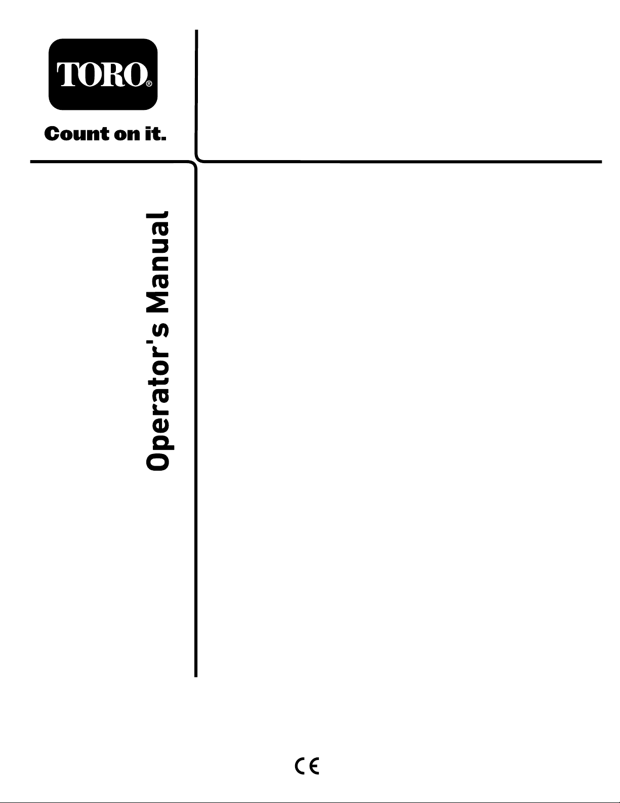
93-7272
1.Cutting/dismembermenthazard,fan—stayawayfrom
movingparts.
decal93-7272
decal106-6755
106-6755
93–6696
1.Storedenergyhazard—readtheOperator'sManual.
106-6754
1.Warning—donottouchthehotsurface.
2.Cutting/dismembermenthazard,fanandentanglement
hazard,belt—stayawayfrommovingparts.
1.Enginecoolantunder
pressure.
2.Explosionhazard—read
decal93-6696
theOperator'sManual.
3.Warning—donottouchthe
hotsurface.
4.Warning—readthe
Operator'sManual.
decal110-9642
110-9642
1.Storedenergyhazard—readtheOperator'sManual.
2.Movethecotterpintotheholeclosesttotherodbracket
decal106-6754
andthenremovetheliftarmandpivotyoke.
110-0986
1.Pressthebrakepedalandparkingbrakepedaltosetthe
parkingbrake.
2.Pressthebrakepedaltoapplythebrake.
3.Pressthetractionpedaltomovethemachineforward.
4.Reelenabledmode
5.Transportmode
decal110-0986
5
Page 6
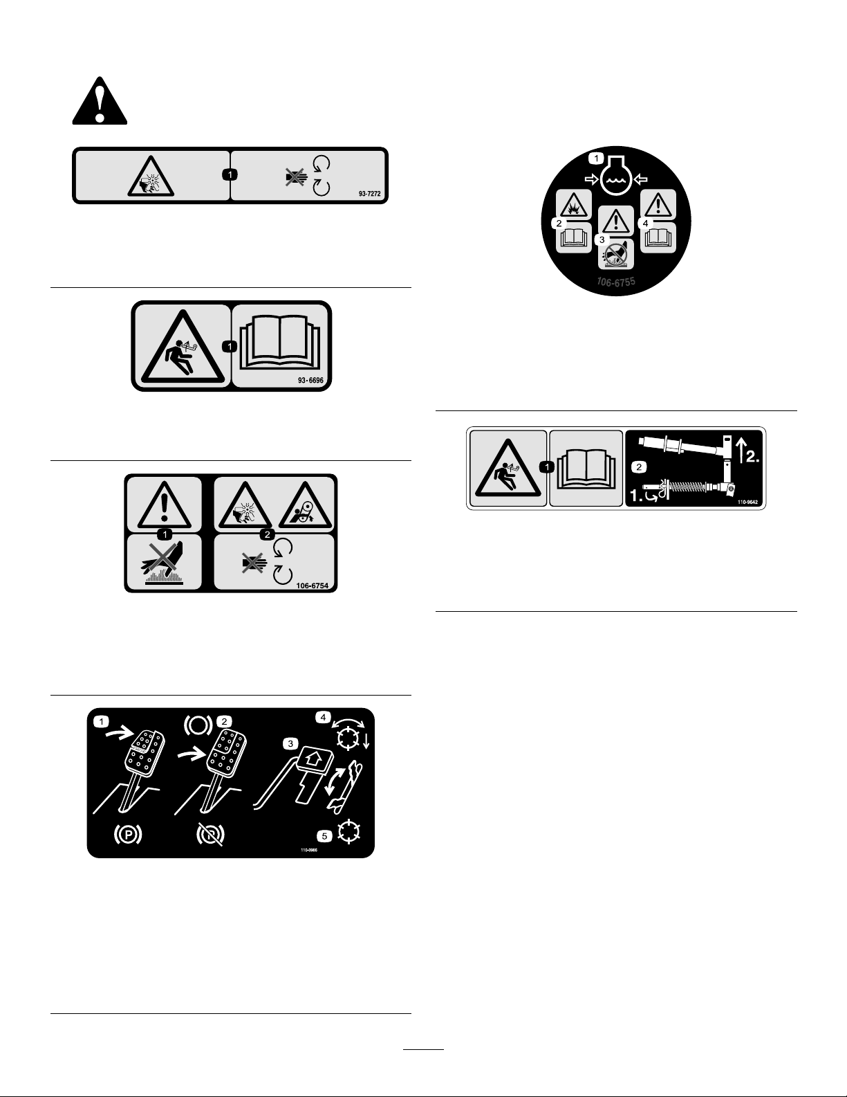
117-0169
1.ReadtheOperator'sManual.
2.Powerpoint(10A)
3.Headlights(10A)
4.Power(10A)
5.Enginestart(15A)
6.Optionalairrideseatsuspension(10A)
7.EnginecomputermanagementC(10A)
8.EnginecomputermanagementB(10A)
9.EnginecomputermanagementA(10A)
decal110-8921
110-8921
1.Tractionunitspeed
2.Slow
3.Fast
r:\decal117-0169
decal117-2718
117–2718
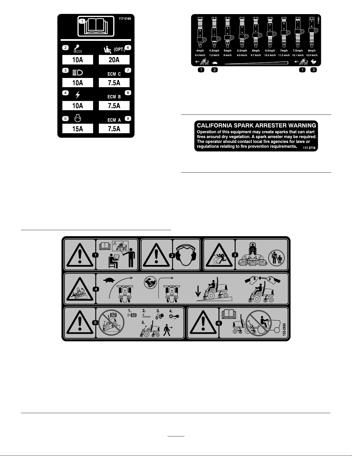
133-2930
1.Warning—readtheOperator'sManual;donotoperatethis
machineunlessyouaretrained.
2.Warning—wearhearingprotection.5.Warning—donotparkonslopes;locktheparkingbrake,shut
3.Thrownobjecthazard—keepbystandersasafedistance
awayfromthemachine.
4.Tippinghazard—slowthemachinebeforeturning;donotturn
athighspeeds;driveonlyonslopeswiththecuttingunits
lowered;alwayswearaseatbelt.
offtheengineandremovetheignitionkeybeforeleavingthe
machine.
6.Warning—readtheOperator'sManual;donottowthe
machine.
6
decal133-2930
Page 7
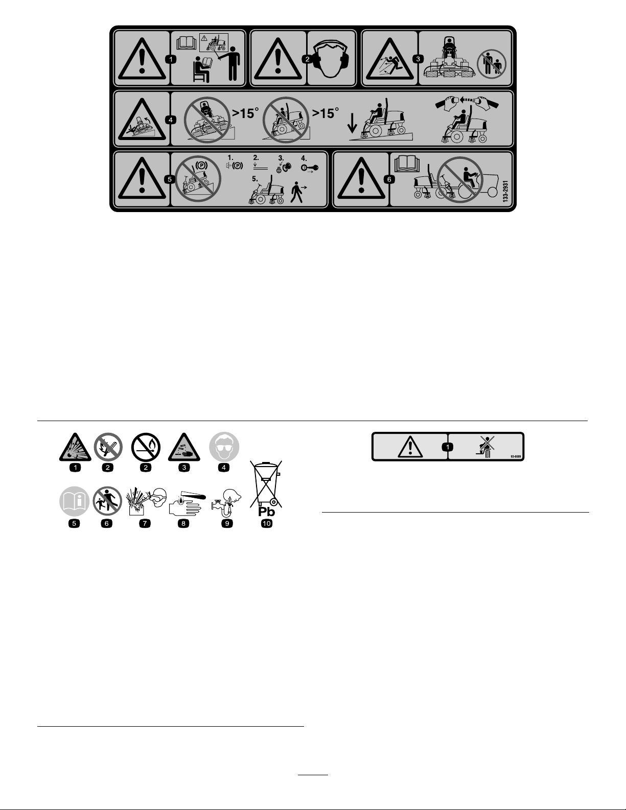
133-2931
(AfxoverPartNo.133-2930)
Note:Thismachinecomplieswiththeindustrystandardstabilitytestinthestaticlateralandlongitudinaltestswiththemaximum
recommendedslopeindicatedonthedecal.ReviewtheinstructionsforoperatingthemachineonslopesintheOperator’sManualas
wellastheconditionsinwhichyouwouldoperatethemachinetodeterminewhetheryoucanoperatethemachineintheconditions
onthatdayandatthatsite.Changesintheterraincanresultinachangeinslopeoperationforthemachine.Ifpossible,keepthe
cuttingunitsloweredtothegroundwhileoperatingthemachineonslopes.Raisingthecuttingunitswhileoperatingonslopescan
causethemachinetobecomeunstable.
decal133-2931
1.Warning—readtheOperator'sManual;donotoperatethis
machineunlessyouaretrained.
4.Tippinghazard—donotdriveacrossordownslopesgreater
than15degrees;onlydriveonslopeswiththecuttingunits
lowered;alwayswearaseatbelt
2.Warning—wearhearingprotection.5.Warning—donotparkonslopes;engagetheparkingbrake,
shutofftheengine,andremovetheignitionkeybeforeleaving
themachine.
3.Thrownobjecthazard—keepbystandersasafedistance
awayfromthemachine
6.Warning—readtheOperator'sManual;donottowthe
machine.
93–6689
1.Danger—noriders.
decalbatterysymbols
BatterySymbols
Someorallofthesesymbolsareonyourbattery .
1.Explosionhazard
2.Nore,opename,or
smoking
3.Causticliquid/chemical
burnhazard
4.Weareyeprotection.9.Flusheyesimmediately
5.ReadtheOperator's
Manual.
6.Keepbystandersasafe
distancefromthebattery.
7.Weareyeprotection;
explosivegasescan
causeblindnessandother
injuries.
8.Batteryacidcancause
blindnessorsevereburns.
withwaterandgetmedical
helpfast.
10.Containslead;donot
discard
decal93-6689
7
Page 8
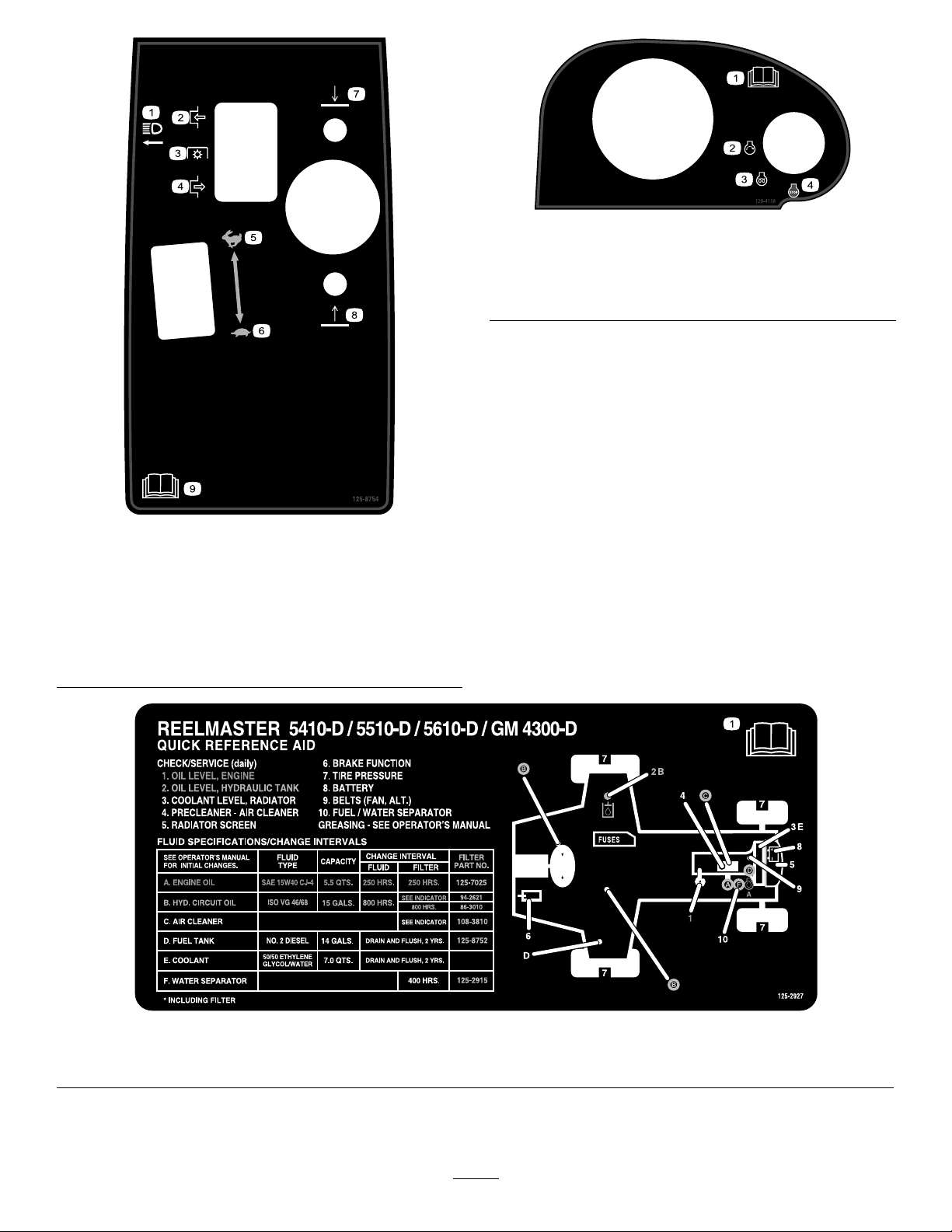
decal120-4158
120–4158
125–8754
1.Headlights
2.Engage7.Lowerthecuttingunits
3.Powertake-off(PTO)
4.Disengage
5.Fast
6.Slow
8.Raisethecuttingunits
9.ReadtheOperator’s
Manual.
1.ReadtheOperator’s
3.Engine—preheat
Manual.
2.Engine—start4.Engine—stop
decal125-8754
1.ReadtheOperator’sManualformaintenanceinformation.
decal125-2927
125–2927
8
Page 9

Setup
LooseParts
Usethechartbelowtoverifythatallpartshavebeenshipped.
ProcedureDescription
1
2
3
4
5
6
Nopartsrequired
Nopartsrequired
Right,fronthoseguide
Left,fronthoseguide
Nopartsrequired
Cutting-unitkickstand
Warningdecal1
MediaandAdditionalParts
Description
Operator'sManual
Engineowner’smanual1
Cuttingperformancepaper
Qty.
Qty.
–
–
1
1
–
1Installthecutting-unitkickstand.
1
1
ReadtheOperator'sManualbeforeoperatingthemachine.
Readthemanualbeforeoperatingtheengine.
Adjustthecutting-unitbedknifetoreel.
Adjustthetirepressure.
Adjustthecontrol-armposition.
Installthecuttingunits.
Adjusttheturf-compensationspring.
ReplacethedecalforCEcompliance.
Use
Use
Shim
1
Adjustthecutting-unitbedknifetoreel.
Note:Determinetheleftandrightsidesofthemachinefromthenormaloperatingposition.
9
Page 10
1
2
AdjustingtheTirePressure
NoPartsRequired
Procedure
Thetiresareover-inatedforshipping.Therefore,
releasesomeoftheairtoreducethepressure.
Correctairpressureinthefrontandreartiresis83
to103kPa(12to15psi).
Important:Maintainevenpressureinalltiresto
ensurethatthereisuniformcontactwiththeturf.
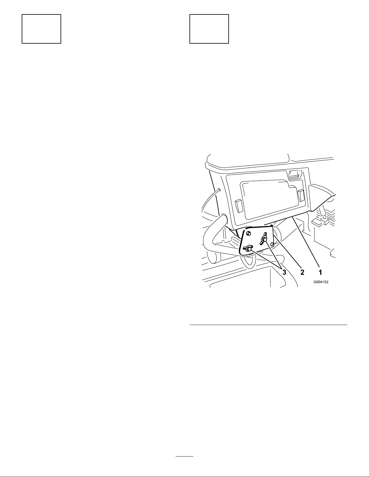
AdjustingtheControl-Arm Position
NoPartsRequired
Procedure
Thecontrol-armpositioncanbeadjustedforyour
comfort.
1.Loosenthe2boltssecuringthecontrolarmto
theretainingbracket(Figure2).
Figure2
1.Controlarm
2.Retainingbrackets
2.Rotatethecontrolarmtothedesiredposition
andtightenthe2bolts.
10
g004152
3.Bolt
Page 11
3
InstallingtheCuttingUnits
Partsneededforthisprocedure:
1
Right,fronthoseguide
1
Left,fronthoseguide
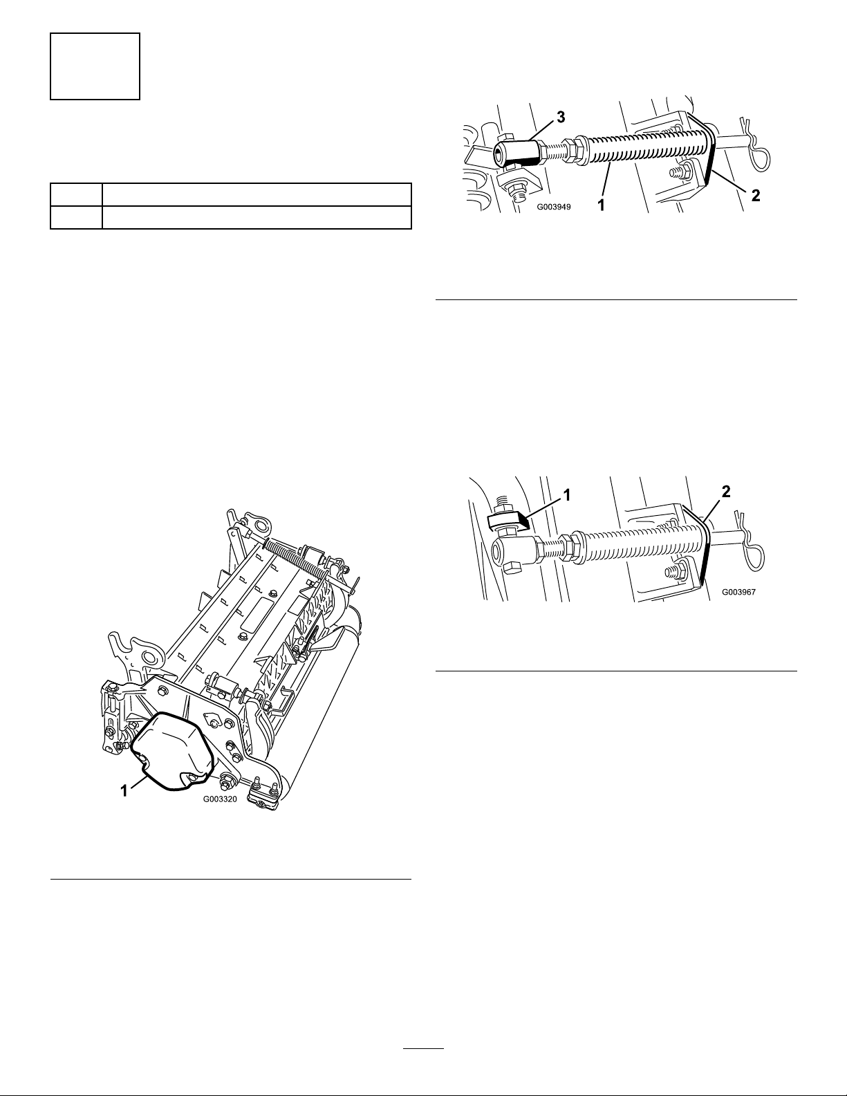
A.Removethe2carriageboltsandnuts
securingtherodbrackettothecutting-unit
tabs(Figure4).
g003949
Figure4
Procedure
1.Removethereelmotorsfromtheshipping
brackets.
Note:Discardtheshippingbrackets.
2.Removethecuttingunitsfromthecartons.
3.Assembleandadjustthecuttingunitsas
describedintheOperator'sManualforthe
cuttingunits.
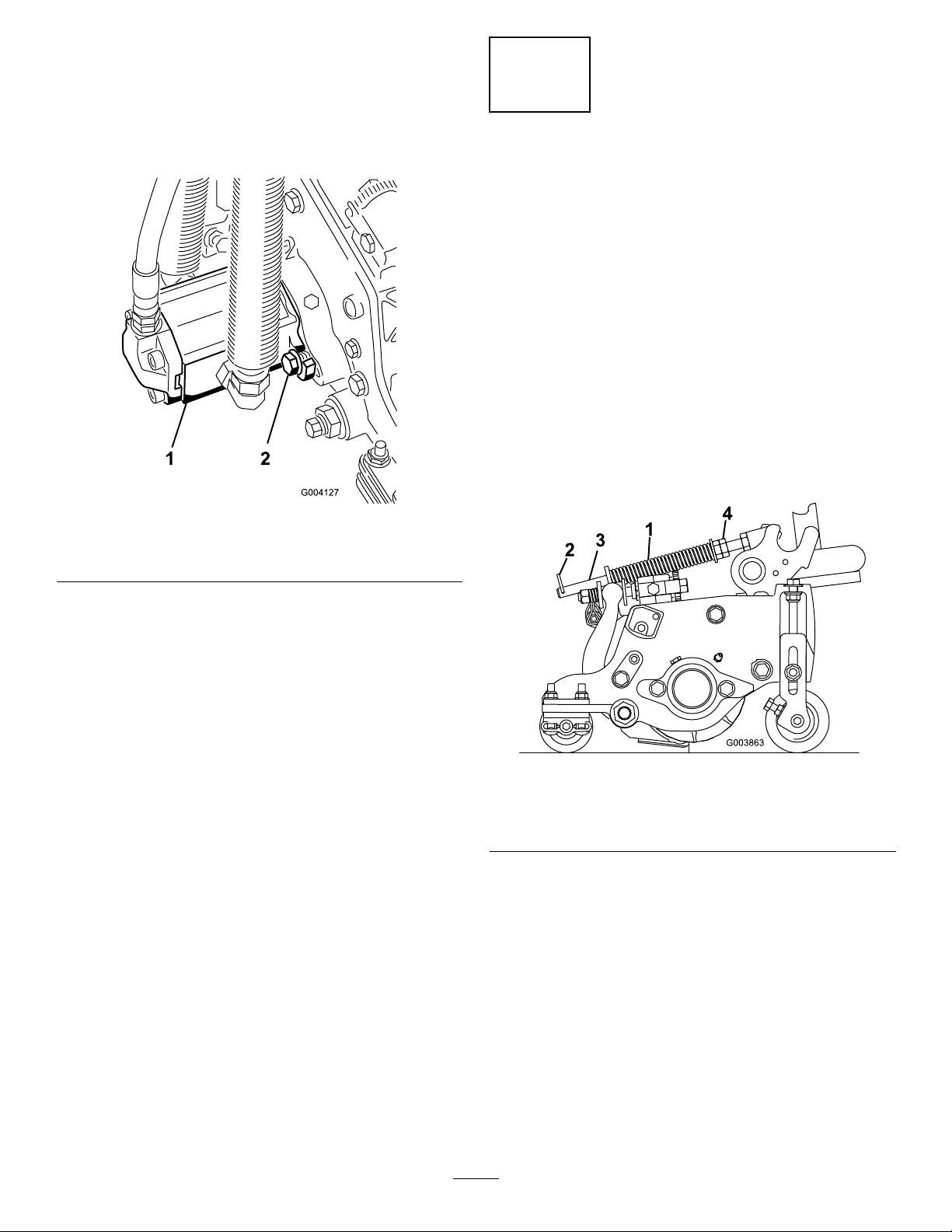
4.Makesurethatthecounterweight(Figure3)is
installedtotheproperendofeachcuttingunit
asdescribedintheOperator'sManualforthe
cuttingunits.
1.Turf-compensationspring3.Springtube
2.Rodbracket
B.Removetheangenutsecuringthe
spring-tubebolttothecarrier-frametab
(Figure4).Removetheassembly.
C.Mountthespring-tubebolttotheopposite
tabonthecarrierframeandsecurewiththe
angenut.
Note:Positiontheboltheadtotheouter
sideofthetabasshowninFigure5.
Figure5
1.Oppositecarrier-frametab
2.Rodbracket
g003967
Figure3
1.Counterweight
5.Mounttheturf-compensationspringtothesame
sideofthecuttingunitasthereel-drivemotor.
Repositiontheturf-compensationspringas
follows:
Note:Allcuttingunitsareshippedwiththe
turf-compensationspringmountedtotheright
sideofthecuttingunit.
D.Mounttherodbrackettothecutting-unit
tabswiththecarriageboltsandnuts(Figure
5).
Important:Oncuttingunit4(leftfront)
andcuttingunit5(rightfront),usethe
rod-bracket-mountingnutstoinstall
g003320
thehoseguidestothefrontofthe
cutting-unittabs(Figure6andFigure7).
Thehoseguidesshouldleantowardthe
centercuttingunit(Figure7andFigure
8).
Note:Wheninstallingorremovingthe
cuttingunits,makesurethatthehairpin
cotterisinstalledinthespring-rodholenext
totherodbracket.Whennotinstallingor
removingthecuttingunits,thehairpincotter
mustbeinstalledintheholeintheendof
therod.
11
Page 12
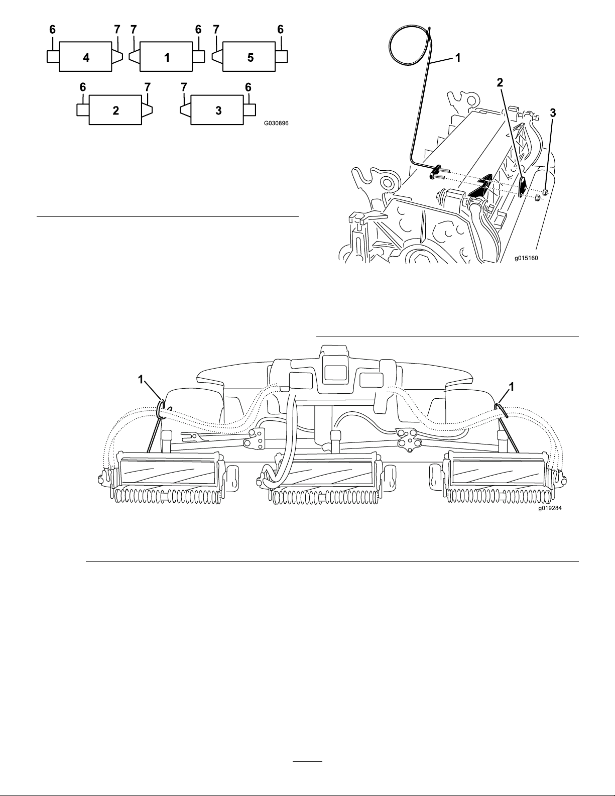
Figure6
1.Cuttingunit15.Cuttingunit5
2.Cuttingunit2
3.Cuttingunit3
4.Cuttingunit4
6.Reelmotor
7.Weight
g030896
g015160
Figure7
1.Hoseguidesmustleantowardthecentercuttingunit.
6.Lowerallliftarmscompletely .
1.Hoseguide(cuttingunit4
shown)
2.Rodbracket
Figure8
3.Nut
g019284
7.Removethesnapperpinandthecapfromthe
lift-arm-pivotyoke(Figure9).
12
Page 13
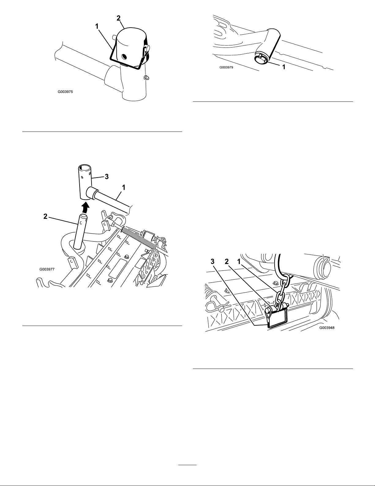
Figure9
1.Snapperpin2.Cap
8.Forthefrontcuttingunits,slideacuttingunit
undertheliftarmwhileinsertingthecarrier-frame
shaftupintothelift-arm-pivotyoke(Figure10).
g003979
Figure11
1.Lynchpinandwasher
g003975
B.Insertthelift-armyokeontothecarrier-frame
shaft(Figure10).
C.Insertthelift-armshaftintotheliftarmand
secureitwiththewasherandlynchpin
(Figure1 1).
10.Insertthecapoverthecarrier-frameshaftand
lift-armyoke.
11.Securethecapandthecarrier-frameshaftto
thelift-armyokewiththesnapperpin(Figure9).
Note:Usetheslotifasteeringcuttingunitis
desiredorusetheholeifthecuttingunitistobe
lockedinposition
12.Securethelift-armchaintothechainbracket
withthesnapperpin(Figure12).
Note:Usethenumberofchainlinksdescribed
intheOperator'sManualforthecuttingunit.
Figure10
1.Liftarm3.Lift-arm-pivotyoke
2.Carrier-frameshaft
9.Usethefollowingprocedureontherearcutting
unitswhentheheightofcutisabove19mm
(3/4inch).
A.Removethelynchpinandwashersecuring
thelift-arm-pivotshafttotheliftarmand
slidethelift-arm-pivotshaftoutofthelift
arm(Figure11).
g003977
g003948
Figure12
1.Lift-armchain
2.Chainbracket
3.Pin
13.Oncuttingunit4(leftfront)andcuttingunit5
(rightfront),insertthereel-motorhosesintothe
respectivehoseguide.
14.Coatthesplineshaftofthereelmotorwithclean
grease.
15.Oilthereel-motorO-ringandinstallitontothe
motorange.
16.Installthemotorbyrotatingitclockwisesothat
themotorangesclearthebolts(Figure13).
13
Page 14
Note:Rotatethemotorcounterclockwiseuntil
theangesencircletheboltsandthentighten
thebolts.
Important:Makesurethatthereel-motor
hosesarenottwisted,kinked,oratriskof
beingpinched.
4
Adjustingthe Turf-CompensationSpring
NoPartsRequired
Procedure
Theturf-compensationspringtransfersweightfrom
thefronttotherearroller(Figure14).Thishelps
toreduceawavepatternintheturf,alsoknownas
marcellingorbobbing.
Important:Makespringadjustmentswiththe
cuttingunitmountedtothetractionunit,pointing
straightaheadandloweredtotheground.
1.Makesurethatthehairpincotterisinstalledin
therearholeinthespringrod(Figure14).
Figure13
1.Reel-drivemotor2.Mountingbolts
g004127
g003863
Figure14
1.Turf-compensationspring3.Springrod
2.Hairpincotter4.Hexnuts
2.Tightenthehexnutsonthefrontendofthe
springroduntilthecompressedlengthofthe
springis12.7cm(5inches)for5-inchcutting
unitsor15.9cm(6.25inches)for7-inchcutting
units(Figure14).
Note:Whenoperatingonroughterrain,
decreasethespringlengthby12.7mm(1/2
inch).Thisslightlydecreasestheground
following.
14
Page 15
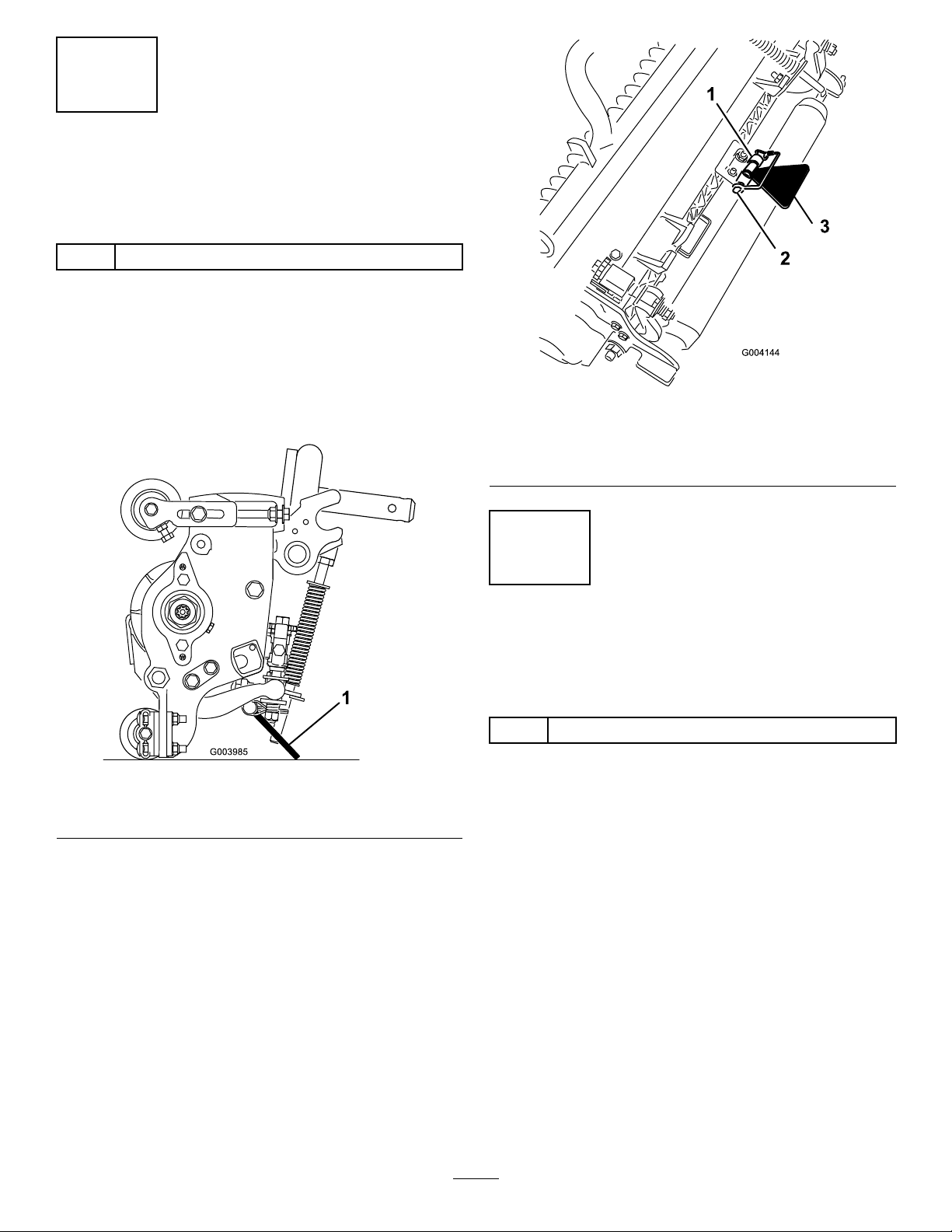
5
UsingtheCutting-Unit Kickstand
Partsneededforthisprocedure:
1
Cutting-unitkickstand
Procedure
Wheneveryouneedtotipthecuttingunittoexpose
thebedknife/reel,propuptherearofthecuttingunit
withthekickstandtomakesurethatthenutsonthe
backendofthebedbar-adjustingscrewsarenot
restingontheworksurface(Figure15).
g004144
Figure16
1.Chainbracket3.Cutting-unitkickstand
2.Snapperpin
Figure15
1.Cutting-unitkickstand
Securethekickstandtothechainbracketwiththe
snapperpin(Figure16).
6
ReplacingtheWarning DecalforCECompliance
Partsneededforthisprocedure:
1Warningdecal
g003985
Procedure
OnmachinesrequiringCECompliance,afxtheCE
warningdecal(PartNo.133-2931)overthestandard
warningdecal(PartNo.133-2930).
15
Page 16
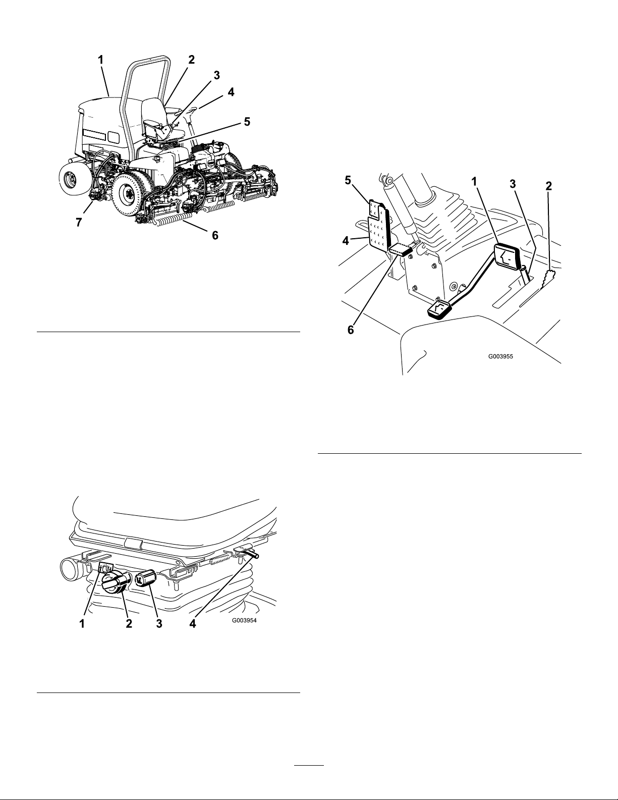
ProductOverview
g216864
Figure17
TractionPedal
Thetractionpedalcontrolstheforwardandreverse
operation(Figure19).Pressthetopofthepedal
tomoveforwardandthebottomtomoverearward.
Groundspeeddependsonhowfaryoupressthe
pedal.Fornoload,maximumgroundspeed,setthe
enginespeedtotheFASTpositionandfullypressthe
pedal.
Tostop,reducefootpressureonthetractionpedal
andallowittoreturntothecenterposition.
1.Enginehood
2.Seat
3.Controlarm
4.Steeringwheel
5.Seatadjustments
6.Frontcuttingunits
7.Rearcuttingunits
Controls
Seat-AdjustingKnobs
Theseat-adjustingleverallowsyoutoadjust
theseatforwardandrearward(Figure18).The
weight-adjustingknobadjuststheseatforyourweight.
Theweightgaugeindicateswhentheseatisadjusted
toyourweight.Theheight-adjustingknobadjuststhe
seatforyourheight.
Figure19
1.Tractionpedal4.Brakepedal
2.Mow-speedlimiter5.Parkingbrake
3.Spacers
6.Tilt-steeringpedal
Mow-SpeedLimiter
Whenthemow-speedlimiterisippedup,itcontrols
themowspeedandallowsthecuttingunitstobe
engaged(Figure19).Eachspaceradjuststhe
mowingspeedby0.8km/h(0.5mph).Themore
spacersyouhaveonthetopofthebolt,theslowerthe
mowingspeed.Totransportthemachine,ipbackthe
mow-speedlimiterforthemaximumtransportspeed.
g003955
Figure18
1.Weightgauge3.Height-adjustingknob
2.Weight-adjustingknob4.Adjustinglever
BrakePedal
g003954
Pressthebrakepedaltostopthemachine(Figure19).
ParkingBrake
Toengagetheparkingbrake,pushdownonthebrake
pedalandpressthetopforwardtolatch(Figure19).
Toreleasetheparkingbrake,pressthebrakepedal
untiltheparking-brakelatchretracts.
16
Page 17

Tilt-SteeringPedal
LowerMow/RaiseControlLever
Totiltthesteeringwheeltowardyou,pressthefoot
pedaldown,pullthesteeringtowertowardyouto
themostcomfortableposition,andreleasethepedal
(Figure19).
Engine-SpeedSwitch
Theengine-speedswitchhas2modestochangethe
enginespeed(Figure20).Bymomentarilytappingthe
switch,youcanchangetheenginespeedin100rpm
increments.Ifyouholdtheswitchdown,theengine
automaticallymovestoHighorLowidle,depending
onwhichendoftheswitchyoupress.
Thisleverraisesandlowersthecuttingunitsandalso
startsandstopsthecuttingunitswhenthecutting
unitsareenabledintheMOWmode(Figure20).You
cannotlowerthecuttingunitswhenthemow/transport
leverisintheTRANSPORTposition.
HeadlightSwitch
Pivottheswitchdownwardtoturnontheheadlights
(Figure20).
BacklapLevers
Usethebacklapleversinconjunctionwiththelower
mow/raisecontrolleverforbacklappingthereels
(Figure21).
Figure20
1.Lowermow/raisecontrol
lever
2.Keyswitch5.Engine-speedswitch
3.InfoCenter
4.Enable/disableswitch
6.Headlightswitch
Enable/DisableSwitch
Usetheenable/disableswitchinconjunctionwiththe
lowermow/raisecontrollevertooperatethecutting
units(Figure20).
InfoCenter
TheInfoCenterLCDdisplayshowsinformationabout
yourmachine,suchastheoperatingstatus,various
diagnostics,andotherinformationaboutthemachine
(Figure20).
KeySwitch
g021208
g021209
Figure21
1.Backlaplevers
Thekeyswitchhas3positions:OFF,ON/RUN,and
START(Figure20).
17
Page 18
Hydraulic-Filter-Restriction
UsingtheInfoCenterLCDDisplay
Indicator
Withtheenginerunningatnormaloperating
temperature,ensurethattheindicatorisinthegreen
zone(Figure22).Whentheindicatorisinthered
zone,changethehydrauliclters.
Figure22
1.Hydraulic-lter-restrictionindicator
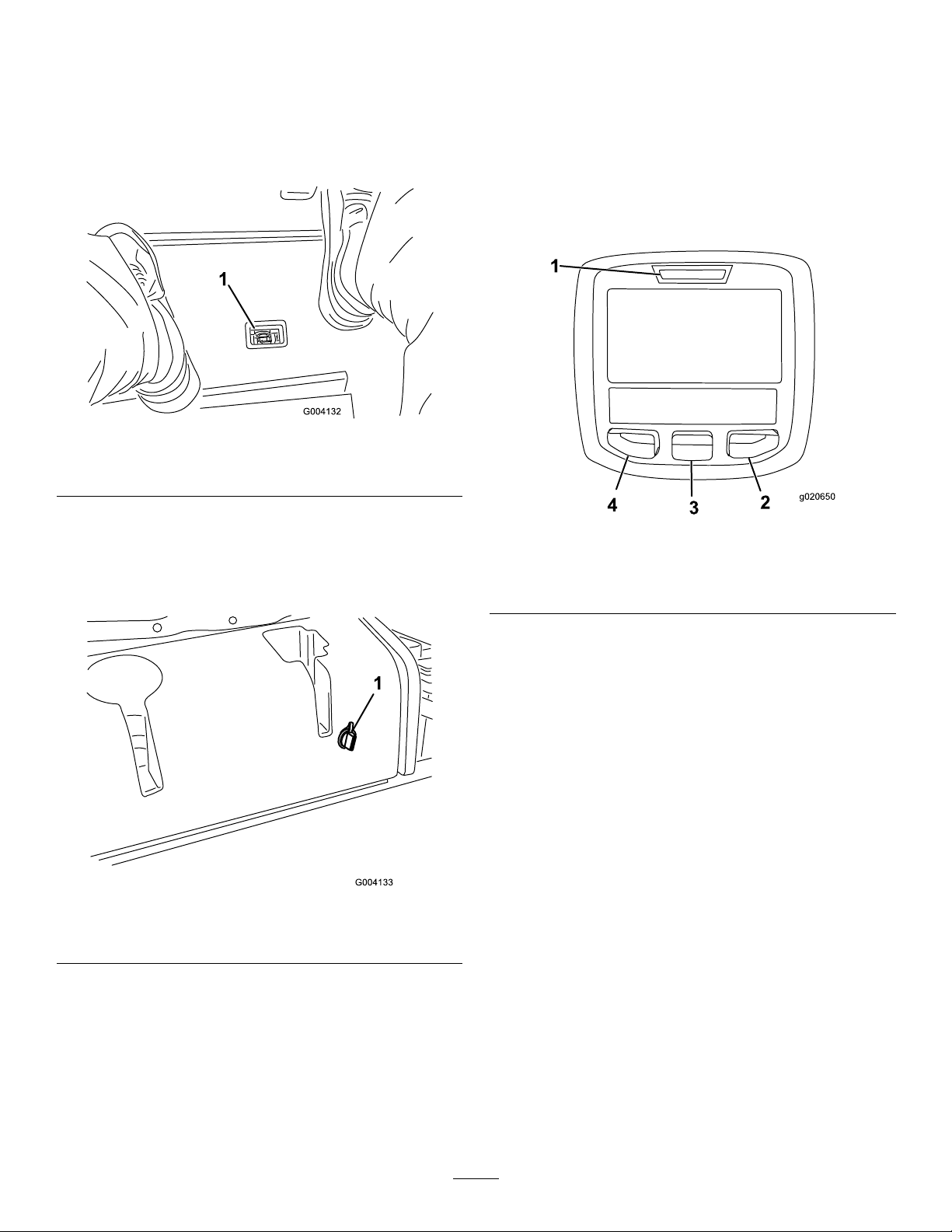
PowerPoint
Thepowerpointisa12Vpowersupplyforelectronic
devices(Figure23).
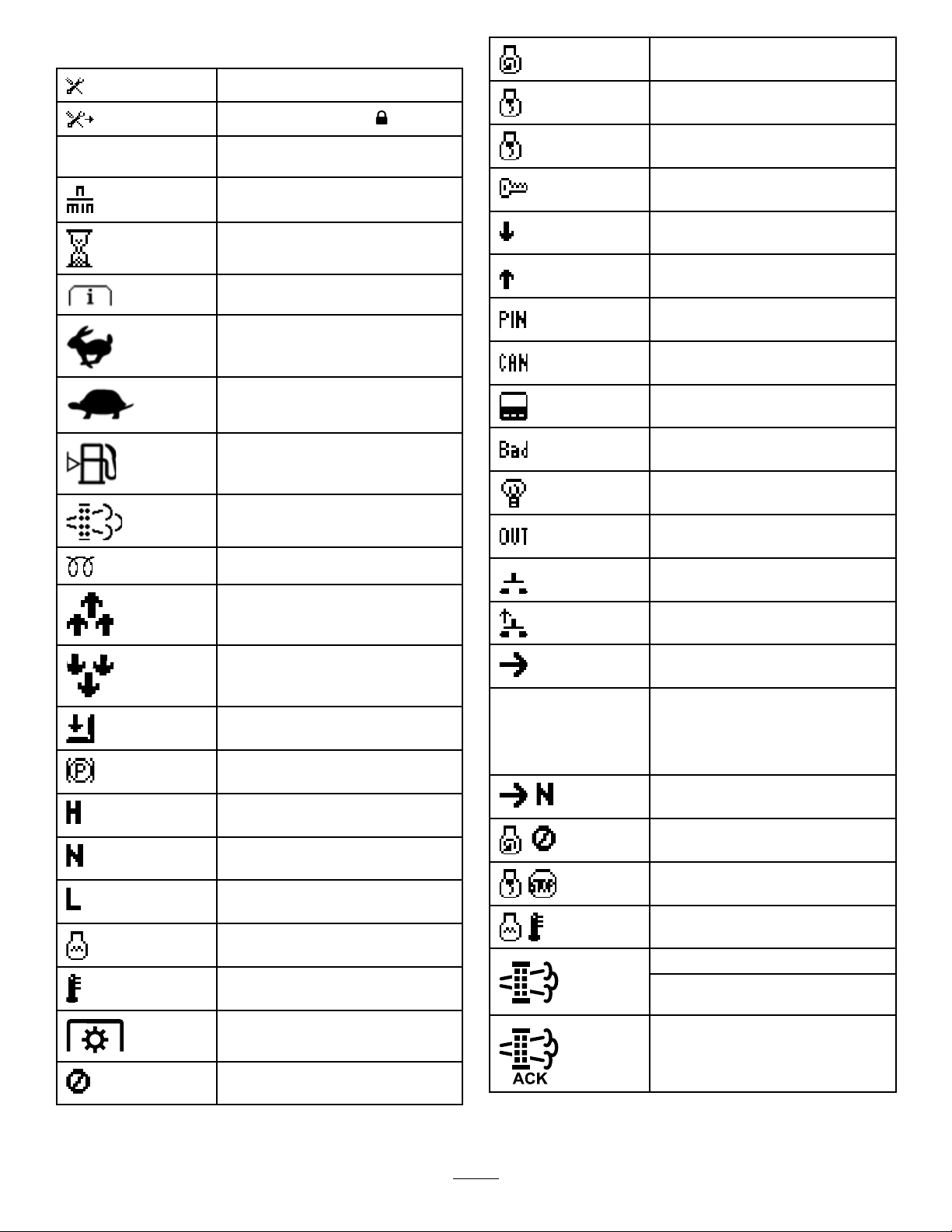
TheInfoCenterLCDdisplayshowsinformationabout
yourmachine,suchastheoperatingstatus,various
diagnostics,andotherinformationaboutthemachine
(Figure24).Thereisasplashscreenandmain
informationscreenoftheInfoCenter.Youcanswitch
betweenthesplashscreenandmaininformation
screen,atanytime,bypressinganyoftheInfoCenter
buttonsandthenselectingtheappropriatedirectional
arrow.
g004132
g020650
Figure24
1.Indicatorlight3.Middlebutton
2.Rightbutton
4.Leftbutton
1.Powerpoint
•LeftButton,MenuAccess/BackButton—Press
thisbuttontoaccesstheInfoCentermenus.
Youcanuseittobackoutofanymenuyouare
currentlyusing.
•MiddleButton—Pressthisbuttontoscrolldown
menus.
•RightButton—Pressthisbuttontoopenamenu
wherearightarrowindicatesadditionalcontent.
Note:Thepurposeofeachbuttonmaychange
dependingonwhatisrequiredatthetime.Each
buttonislabeledwithanicondisplayingitscurrent
function.
g004133
Figure23
18
Page 19
InfoCenterIconDescription
Starttheengine.
SERVICEDUE
Hoursremaininguntilservice
Resettheservicehours
Indicateswhenscheduledservice
shouldbeperformed
Enginerpm/status—indicatesthe
enginespeed(rpm)
Hourmeter
Infoicon
Fast
Slow
Fuellevel
Stationaryregenerationisrequired.
Theglowplugsareactive.
Raisethecuttingunits.
Shutofftheengine.
Engine
Keyswitch
Thecuttingunitsarelowering.
Thecuttingunitsareraising.
PINcode
CANbus
InfoCenter
Badorfailed
Bulb
OutputofTECcontrollerorcontrol
wireinharness
Switch
Releasetheswitch.
Lowerthecuttingunits.
Sitintheseat.
ParkingbrakeisOn.
Therangeishigh(transport).
Neutral
Therangeislow(mow).
Engine-coolanttemperature(°Cor
°F)
Temperature(hot)
ThePTOisengaged.
Notallowed
Changetotheindicatedstate.
Symbolsareoften
combinedtoform
sentences.Some
examplesareshown
below
PutthemachineintoNeutral.
Enginestartisdenied.
Engineshutdown
Enginecoolantistoohot.
Reset-standbyregenerationrequest
Parkedorrecoveryregeneration
request
Aparkedorrecoveryregenerationis
processing.
19
Page 20
Highexhausttemperature
DPFash-accumulation
notication—RefertoDPFAsh
Accumulation(page31)fordetails.
Sitdownorengagetheparkingbrake
UsingtheMenus
ToaccesstheInfoCentermenusystem,pressthe
menuaccessbuttonwhileatthemainscreen.This
bringsyoutothemainmenu.Refertothefollowing
tablesforasynopsisoftheoptionsavailablefrom
themenus:
MainMenu
MenuItemDescription
Faults
ServiceContainsinformationonthe
Diagnostics
Settings
AboutListsthemodelnumber,serial
Service
MenuItemDescription
Hours
Counts
DPFRegeneration
Containsalistoftherecent
machinefaults.Refertothe
ServiceManualorcontactyour
authorizedTorodistributorfor
moreinformationontheFaults
menuandtheinformation
containedthere.
machinesuchashoursof
usecountersandothersimilar
numbers.
Displaysthestateofeach
machineswitch,sensorand
controloutput.Y oucanuse
thistotroubleshootcertain
issuesasitquicklytellsyou
whichmachinecontrolsareon
andwhichareoff.
Allowsyoutocustomizeand
modifycongurationvariables
ontheInfoCenterdisplay.
number,andsoftwareversion
ofyourmachine.
Liststhetotalnumberofhours
thatthemachine,engineand
PTOhavebeenon,aswell
asthenumberofhoursthe
machinehasbeentransported
andservicedue.
Listsnumerouscountsthe
machinehasexperienced.
Thedieselparticulatelter
regenerationoptionandDPF
submenus
InhibitRegenUsetocontrolreset
ParkedRegenUsetoinitiateaparked
LastRegenListsthenumberhourssince
RecoverRegenUsetoinitiatearecovery
Diagnostics
MenuItemDescription
CuttingUnitsIndicatestheinputs,qualiers
Hi/LowRangeIndicatestheinputs,qualiers
PTOIndicatestheinputs,qualiers
EngineRun
Backlap
Settings
MenuItemDescription
Units
Language
LCDBacklightControlsthebrightnessofthe
LCDContrastControlsthecontrastofthe
FrontBacklapReelSpeedControlsthespeedofthefront
RearBacklapReelSpeedControlsthespeedoftherear
ProtectedMenusAllowsapersonauthorized
AutoIdle
BladeCount
MowSpeed
regeneration
regeneration
thelastreset,parked,or
recoveryregeneration
regeneration
andoutputsforraisingand
loweringthecuttingunits.
andoutputsfordrivingin
transportmode.
andoutputsforenablingthe
PTOcircuit.
Indicatestheinputs,qualiers
andoutputsforstartingthe
engine.
Indicatestheinputs,qualiers
andoutputsforoperatingthe
backlapfunction.
Controlstheunitsusedonthe
InfoCenter.Themenuchoices
areEnglishorMetric
Controlsthelanguageused
ontheInfoCenter*.
LCDdisplay.
LCDdisplay.
reelsinbacklapmode.
reelsinbacklapmode.
byyourcompanywiththe
PINcodetoaccessprotected
menus.
Controlstheamountoftime
allowedbeforereturningthe
enginetolowidlewhenthe
machineisstationary.
Controlsthenumberofblades
onthereelforreelspeed.
Controlsthegroundspeedfor
determiningthereelspeed.
20
Page 21
Heightofcut(HOC)
FReelRPM
RReelRPM
Controlstheheightofcut
(HOC)fordeterminingthereel
speed.
Displaysthecalculatedreel
speedpositionforthefront
reels.Thereelscanalsobe
manuallyadjusted.
Displaysthecalculatedreel
speedpositionfortherear
reels.Thereelscanalsobe
manuallyadjusted.
*Onlyoperator-facedtextistranslated.Faults,
Service,andDiagnosticsscreensareservice-faced.
Titlesappearintheselectedlanguage,butmenu
itemsareinEnglish.
ProtectedunderProtectedMenus—accessibleonly
byenteringPIN
AccessingProtectedMenus
Note:ThefactorydefaultPINcodeforyoumachine
iseither0000or1234.
IfyouchangedthePINcodeandforgotthecode,
contactyourauthorizedT orodistributorforassistance.
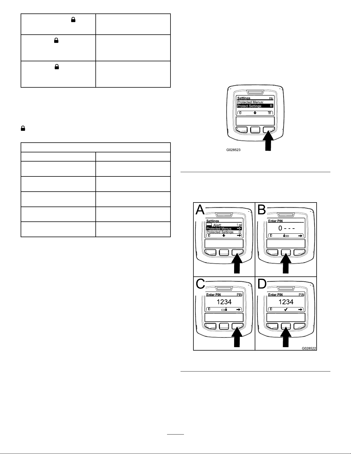
1.FromtheMAINMENU,usethecenterbuttonto
scrolldowntotheSETTINGSMENUandpressthe
rightbutton(Figure25).
About
MenuItemDescription
Model
SNListstheserialnumberofthe
Machine-ControllerRevisionListsthesoftwarerevisionof
InfoCenterRevisionListsthesoftwarerevisionof
CANBus
Liststhemodelnumberofthe
machine.
machine.
themastercontroller .
theInfoCenter.
Liststhemachine
communicationbusstatus.
ProtectedMenus
Thereare8operatingcongurationsettingsthatare
adjustablewithintheSettingsMenuoftheInfoCenter:
autoidletimedelay ,BladeCount,MowSpeed,Height
ofCut(HOC),FReelRPM,andRReelRPM.These
settingscanbelockedbyusingtheProtectedMenu.
Note:Atthetimeofdelivery ,theinitialpassword
codeisprogrammedbyyourdistributor.
g028523
Figure25
2.IntheSETTINGSMENU,usethecenterbuttonto
scrolldowntothePROTECTEDMENUandpress
therightbutton(Figure26A).
Figure26
3.ToenterthePINcode,pressthecenterbutton
untilthecorrectrstdigitappears,thenpress
therightbuttontomoveontothenextdigit
(Figure26BandFigure26C).Repeatthisstep
untilthelastdigitisenteredandpresstheright
buttononcemore.
21
g028522
Page 22

4.PressthemiddlebuttontoenterthePINcode
(Figure26D).
WaituntiltheredindicatorlightoftheInfoCenter
illuminates.
Note:IftheInfoCenteracceptsthePINcode
andtheprotectedmenuisunlocked,theword
“PIN”displaysintheupperrightcornerofthe
screen.
Note:RotatethekeyswitchtotheOFFpositionand
thentotheONpositionlockstheprotectedmenu.
Youhavetheabilitytoviewandchangethesettingsin
theProtectedMenu.OnceyouaccesstheProtected
Menu,scrolldowntoProtectSettingsoption.Usethe
rightbuttontochangethesetting.SettingtheProtect
SettingstoOFFallowsyoutoviewandchangethe
settingsintheProtectedMenuwithoutenteringthe
PINcode.SettingtheProtectSettingstoONhidesthe
protectedoptionsandrequiresyoutoenterthePIN
codetochangethesettingintheProtectedMenu.
AfteryousetthePINcode,rotatethekeyswitchOFF
andbacktotheONpositiontoenableandsavethis
feature.
SettingtheMowSpeed
1.IntheSettingsMenu,scrolldowntoMowSpeed.
2.Presstherightbuttontoselectmowspeed.
3.Usethecenterandrightbuttontoselectthe
appropriatemowspeedsetonthemechanical
mow-speedlimiteronthetractionpedal.
4.Presstheleftbuttontoexitmowspeedandsave
thesetting.
SettingtheHeightofCut(HOC)
1.IntheSettingsMenu,scrolldowntoHOC.
2.PresstherightbuttontoselectHOC.
3.Usethecenterandrightbuttontoselectthe
appropriateHOCsetting.(Iftheexactsettingis
notdisplayed,selectthenearestHOCsetting
fromthelistdisplayed).
4.PresstheleftbuttontoexitHOCandsavethe
setting.
SettingtheFrontandRearReel
ViewingandChangingthe
ProtectedMenuSettings
1.IntheProtectedMenu,scrolldowntoProtect
Settings.
2.Toviewandchangethesettingswithoutentering
apasscode,usetherightbuttontochangethe
ProtectSettingstoOFF.
3.Toviewandchangethesettingswitha
passcode,usetheleftbuttontochangethe
ProtectSettingstoON,setthepasscode,and
turnthekeyintheignitionswitchtotheOFF
positionandthentotheONposition.
SettingtheAutoIdle
1.IntheSettingsMenu,scrolldowntoAutoIdle.
2.Presstherightbuttontochangetheautoidle
timebetweenOFF,8S,10S,15S,20S,and30S.
SettingtheBladeCount
Speeds
Althoughthefrontandrearreelspeedsarecalculated
byinputtingthenumberofblades,mowspeedand
HOCintotheInfoCenter,thesettingcanbemanually
changedtoaccommodatefordifferentmowing
conditions.
1.TochangetheReelSpeedSettings,scrolldown
totheFReelRPM,RReelRPM,orboth.
2.Presstherightbuttontochangethereelspeed
value.Asyouchangethespeedsetting,the
displaycontinuestoshowthecalculatedreel
speedbasedonbladecount,mowspeedand
HOC,whichwaspreviouslyentered,butthe
newvalueisalsodisplayed.
1.IntheSettingsMenu,scrolldowntoBlade
Count.
2.Presstherightbuttontochangethebladecount
between5,8,or11bladereels.
22
Page 23

Specications
Note:Specicationsanddesignaresubjectto
changewithoutnotice.
SpecicationReelMaster®5410-DReelMaster®5510-D
Transportwidth
Widthofcut254cm(100inches)254cm(100inches)
Length
Height
Weight
(withuidsand8bladecuttingunitsinstalled)
Engine
Fuel-tankcapacity
Transportspeed
Mowingspeed
Attachments/Accessories
AselectionofToroapprovedattachmentsandaccessoriesisavailableforusewiththemachinetoenhance
andexpanditscapabilities.ContactyourAuthorizedServiceDealerorDistributororgotowww.T oro.comfora
listofallapprovedattachmentsandaccessories.
228cm(90inches)233cm(92inches)
282cm(111inches)282cm(1 11inches)
160cm(63inches)160cm(63inches)
1,335kg(2,943lb)1,420kg(3,131lb)
Yanmar
36hp
53L(14USgallons)53L(14USgallons)
0to16km/h(0to10mph)0to16km/h(0to10mph)
0to13km/h(0to8mph)0to13km/h(0to8mph)
Yanmar
36hp
TobestprotectyourinvestmentandmaintainoptimalperformanceofyourToroequipment,countonT oro
genuineparts.Whenitcomestoreliability,Torodeliversreplacementpartsdesignedtotheexactengineering
specicationofourequipment.Forpeaceofmind,insistonTorogenuineparts.
23
Page 24

Operation
FillingtheFuelTank
Note:Determinetheleftandrightsidesofthe
machinefromthenormaloperatingposition.
BeforeOperationSafety
GeneralSafety
•Neverallowchildrenoruntrainedpeopleto
operateorservicethemachine.Localregulations
mayrestricttheageoftheoperator.Theowner
isresponsiblefortrainingalloperatorsand
mechanics.
•Becomefamiliarwiththesafeoperationofthe
equipment,operatorcontrols,andsafetysigns.
•Knowhowtostopthemachineandshutoffthe
enginequickly.
•Checkthatoperator-presencecontrols,safety
switches,andshieldsareattachedandfunctioning
properly.Donotoperatethemachineunlessthey
arefunctioningproperly.
•Beforemowing,alwaysinspectthemachineto
ensurethattheblades,bladebolts,andcutting
assembliesareingoodworkingcondition.
Replacewornordamagedbladesandboltsinsets
topreservebalance.
•Inspecttheareawhereyouwillusethemachine
andremoveallobjectsthatthemachinecould
throw.
FuelSafety
•Useextremecareinhandlingfuel.Itisammable
anditsvaporsareexplosive.
•Extinguishallcigarettes,cigars,pipes,andother
sourcesofignition.
•Useonlyanapprovedfuelcontainer.
•Donotremovethefuelcaporllthefueltank
whiletheengineisrunningorhot.
•Donotaddordrainthefuelinanenclosedspace.
•Donotstorethemachineorfuelcontainerwhere
thereisanopename,spark,orpilotlight,such
asonawaterheaterorotherappliance.
•Ifyouspillfuel,donotattempttostarttheengine;
avoidcreatinganysourceofignitionuntilthefuel
vaporshavedissipated.
FuelTankCapacity
53L(14USgallons)
FuelSpecication
Important:Useonlyultra-lowsulphurdiesel
fuel.Fuelwithhigherratesofsulfurdegrades
thedieseloxidationcatalyst(DOC),whichcauses
operationalproblemsandshortenstheservicelife
ofenginecomponents.
Failuretoobservethefollowingcautionsmay
damagetheengine.
•Neverusekeroseneorgasolineinsteadofdiesel
fuel.
•Nevermixkeroseneorusedengineoilwiththe
dieselfuel.
•Neverkeepfuelincontainerswithzincplatingon
theinside.
•Donotusefueladditives.
PetroleumDiesel
Cetanerating:45orhigher
Sulfurcontent:Ultra-lowsulfur(<15ppm)
FuelTable
Dieselfuelspecication
ASTMD975
No.1-DS15
No.2-DS15
EN590EuropeanUnion
ISO8217DMX
JISK2204GradeNo.2
KSM-2610
•Useonlyclean,freshdieselfuelorbiodieselfuels.
•Purchasefuelinquantitiesthatcanbeusedwithin
180daystoensurefuelfreshness.
Usesummer-gradedieselfuel(No.2-D)at
temperaturesabove-7°C(20°F)andwinter-grade
fuel(No.1-DorNo.1-D/2-Dblend)belowthat
temperature.
Note:Useofwinter-gradefuelatlowertemperatures
provideslowerashpointandcoldowcharacteristics
whicheasesstartingandreducesfuellterplugging.
Usingsummer-gradefuelabove-7°C(20°F)
contributestowardlongerfuelpumplifeandincreased
powercomparedtowinter-gradefuel.
Location
USA
International
Japan
Korea
24
Page 25

Biodiesel
Thismachinecanalsouseabiodieselblendedfuelof
uptoB20(20%biodiesel,80%petroleumdiesel).
Sulfurcontent:Ultra-lowsulfur(<15ppm)
Biodieselfuelspecication:ASTMD6751or
EN14214
Blendedfuelspecication:ASTMD975,EN590,
orJISK2204
Important:Thepetroleumdieselportionmust
beultra-lowsulfur.
Observethefollowingprecautions:
•Biodieselblendsmaydamagepaintedsurfaces.
•UseB5(biodieselcontentof5%)orlesserblends
incoldweather.
•Monitorseals,hoses,gasketsincontactwithfuel
astheymaybedegradedovertime.
•Fuellterpluggingmaybeexpectedforatime
afterconvertingtobiodieselblends.
•ContactyourauthorizedT orodistributorifyouwish
formoreinformationonbiodiesel.
CheckingtheEngine-Oil Level
Beforeyoustarttheengineandusethemachine,
checktheoillevelintheenginecrankcase;referto
CheckingtheEngine-OilLevel(page53).
AddingFuel
1.Parkthemachineonalevelsurface,lowerthe
cuttingunits,shutofftheengine,andremove
thekey .
2.Usingacleanrag,cleanareaaroundfuel-tank
cap.
3.Removethecapfromthefueltank(Figure27).
Figure27
1.Fuel-tankcap
4.Fillthetankuntilthelevelis6to13mm(1/4to
1/2inch)belowthebottomofthellerneck.
g021210
5.Installthefuel-tankcaptightlyafterllingthe
tank.
Note:Ifpossible,llthefueltankaftereachuse.
Thisminimizespossiblebuildupofcondensation
insidethefueltank.
25
Page 26

CheckingtheCooling
CheckingtheHydraulic
System
ServiceInterval:Beforeeachuseordaily
Cleandebrisoffthescreen,oilcooler,andfrontof
theradiatordailyandmoreoftenifconditionsare
extremelydustyanddirty .RefertoRemovingDebris
fromtheCoolingSystem(page59).
Thecoolingsystemislledwitha50/50solution
ofwaterandpermanentethyleneglycolantifreeze.
Checkthelevelofcoolantintheexpansiontankatthe
beginningofeachdaybeforestartingtheengine.The
capacityofthecoolingsystemis6.6L(7.0USqt).
CAUTION
Iftheenginehasbeenrunning,the
pressurized,hotcoolantcanescapeand
causeburns.
•Donotopentheradiatorcapwhenthe
engineisrunning.
•Usearagwhenopeningtheradiatorcap,
andopenthecapslowlytoallowsteamto
escape.
1.Checkthelevelofcoolantintheexpansiontank
(Figure28).
Thecoolantlevelshouldbebetweenthemarks
onthesideofthetank.
Fluid
ServiceInterval:Beforeeachuseordaily
Themachinesreservoirislledatthefactorywith
approximately30L(8USgallons)ofhigh-quality
hydraulicuid.Checkthelevelofthehydraulicuid
beforetheengineisrststartedanddailythereafter.
Therecommendedreplacementuidisasfollows:
ToroPremiumAllSeasonHydraulicFluid(Availablein
19L(5USgallon)pailsor208L(55USgallon)drums.
SeethePartsCatalogoryourauthorizedTorodistributor
forpartnumbers.)
Alternateuids:IftheT orouidisnotavailable,other
uidsmaybeusedprovidedtheymeetallthefollowing
materialpropertiesandindustryspecications.Do
notusesyntheticuid.Consultwithyourlubricant
distributortoidentifyasatisfactoryproduct.
Note:T orodoesnotassumeresponsibilityfor
damagecausedbyimpropersubstitutions,souse
onlyproductsfromreputablemanufacturerswho
standbehindtheirrecommendation.
HighViscosityIndex/LowPourPointAnti-wearHydraulic
Fluid,ISOVG46
MaterialProperties:
Viscosity,ASTMD445cSt@40°C44to50
ViscosityIndexASTMD2270
PourPoint,ASTMD97-36.6°C(-34°F)to9.4°C
IndustrySpecications:
VickersI-286-S(QualityLevel),VickersM-2950-S(Quality
Level),DenisonHF-0
Important:TheISOVG46Multigradeuid
hasbeenfoundtoofferoptimalperformance
inawide-rangeoftemperatureconditions.
Foroperationinconsistentlyhighambient
temperatures,18°C(65°F)to49°C(120°F),
ISOVG68hydraulicuidmayofferimproved
performance.
cSt@100°C7.9to8.5
140to160
(-49°F)
Figure28
1.Expansiontank
2.Ifthecoolantlevelislow,removethe
expansion-tankcapandreplenishthesystem.
Donotoverll.
3.Installtheexpansion-tankcap.
PremiumBiodegradableHydraulicFluid-Mobil
EALEnviroSyn46H
Important:MobilEALEnviroSyn46Histheonly
g021866
syntheticbiodegradableuidapprovedbyToro.
Thisuidiscompatiblewiththeelastomersused
inTorohydraulicsystemsandissuitablefora
wide-rangeoftemperatureconditions.Thisuidis
compatiblewithconventionalmineraloils,butfor
maximumbiodegradabilityandperformance,the
hydraulicsystemshouldbethoroughlyushed
ofconventionaluid.Theoilisavailablein19L
(5USgallon)containersor208L(55USgallon)
drumsfromyourMobildistributor.
Important:Manyhydraulicuidsarealmost
colorless,makingitdifculttospotleaks.A
26
Page 27

reddyeadditiveforthehydraulicsystemoil
isavailablein20ml(2/3oz)bottles.1bottle
issufcientfor15to22L(4to6gallons)of
hydraulicoil.OrderPartNumber44-2500from
yourauthorizedT orodistributor.Thisreddyeis
notrecommendedforusewithbiodegradable
uids.Usefoodcoloring.
1.Positionthemachineonalevelsurface,lower
thecuttingunits,andshutofftheengine.
2.Cleantheareaaroundthellerneckandcapof
thehydraulictank(Figure29).Removethecap
fromthellerneck.
Figure29
1.Hydraulic-tankcap
CheckingtheTorqueofthe WheelNuts
ServiceInterval:Afterthersthour
Aftertherst10hours
Every250hours
Torquethewheelnutsto94to122N∙m(70to90ft-lb).
WARNING
Failuretomaintainpropertorqueofthewheel
nutscouldresultinpersonalinjury.
Maintainthepropertorqueonthewheelnuts.
BurnishingtheBrakes
Toensureoptimumperformanceoftheparking-brake
system,burnish(breakin)thebrakesbeforeuse.
Settheforwardtractionspeedto6.4km/h(4mph)
tomatchthereversetractionspeed(all8spacers
movedtothetopofthemow-speedcontrol).With
theengineathighidle,proceedforwardwiththe
mow-speed-controlstopengagedandridethebrake
g021215
for15seconds.Proceedbackwardatfullreverse
speedandridethebrakefor15seconds.Repeatthis
5times,waiting1minutebetweeneachforwardand
reversecycletoavoidoverheatingthebrakes;referto
AdjustingtheParkingBrakes(page60).
3.Removethedipstickfromthellerneckand
wipeitwithacleanrag.
4.Insertthedipstickintothellerneck;then
removeitandchecktheleveloftheuid.
Note:Theuidlevelshouldbewithin6.3mm
(1/4inch)ofthemarkonthedipstick.
Important:Donotoverll.
5.Ifthelevelislow,addappropriateuidtoraise
theleveltotheFULLmark.
6.Installthedipstickandcapontothellerneck.
Checkingthe Reel-to-BedknifeContact
ServiceInterval:Beforeeachuseordaily
Eachdaybeforeoperating,checkreel-to-bedknife
contact,regardlessifthequalityofcuthadpreviously
beenacceptable.Theremustbelightcontactacross
thefulllengthofthereelandthebedknife(refer
toAdjustingtheReeltoBedknifeintheOperator's
Manualforthecuttingunits).
27
Page 28

DuringOperationSafety
GeneralSafety
•Theowner/operatorcanpreventandisresponsible
foraccidentsthatmaycausepersonalinjuryor
propertydamage.
•Wearappropriateclothing,includingeye
protection;slip-resistant,substantialfootwear;
longpants;andhearingprotection.Tiebacklong
hairanddonotweardanglingjewelry.
•Donotoperatethemachinewhileill,tired,or
undertheinuenceofalcoholordrugs.
•Nevercarrypassengersonthemachineandkeep
bystandersandpetsawayfromthemachine
duringoperation.
•Operatethemachineonlyingoodvisibilitytoavoid
holesorhiddenhazards.
•Avoidmowingonwetgrass.Reducedtraction
couldcausethemachinetoslide.
•Beforeyoustarttheengine,ensurethatalldrives
areinneutral,theparkingbrakeisengaged,and
youareintheoperatingposition.
•Keepyourhandsandfeetawayfromthecutting
units.Keepclearofthedischargeopeningatall
times.
•Lookbehindanddownbeforebackinguptobe
sureofaclearpath.
•Usecarewhenapproachingblindcorners,shrubs,
trees,orotherobjectsthatmayobscureyour
vision.
•Donotmowneardrop-offs,ditches,or
embankments.Themachinecouldsuddenlyroll
overifawheelgoesovertheedgeoriftheedge
givesway .
•Stopthecuttingunitswheneveryouarenot
mowing.
•Stopthemachineandinspectthecuttingunits
afterstrikinganobjectorifthereisanabnormal
vibrationinthemachine.Makeallnecessary
repairsbeforeresumingoperation.
•Slowdownandusecautionwhenmakingturns
andcrossingroadsandsidewalkswiththe
machine.Alwaysyieldtheright-of-way.
•Disengagethedrivetothecuttingunitandshut
offtheenginebeforeadjustingtheheightof
cut(unlessyoucanadjustitfromtheoperating
position).
•Neverrunanengineinanareawhereexhaust
gassesareenclosed.
•Neverleavearunningmachineunattended.
•Beforeleavingtheoperatingposition(including
toemptythecatchersortounclogthechute),do
thefollowing:
–Parkthemachineonlevelground.
–Disengagethepowertake-offandlowerthe
attachments.
–Engagetheparkingbrake.
–Shutofftheengineandremovethekey .
–Waitforallmovingpartstostop.
•Donotoperatethemachinewhenthereistherisk
oflightning.
•Donotusethemachineasatowingvehicle.
•Useaccessories,attachments,andreplacement
partsapprovedbyTheT oro®Companyonly.
RolloverProtectionSystem (ROPS)Safety
•DonotremovetheROPSfromthemachine.
•Ensurethattheseatbeltisattachedandthatyou
canreleaseitquicklyinanemergency.
•Checkcarefullyforoverheadobstructionsanddo
notcontactthem.
•KeeptheROPSinsafeoperatingconditionby
thoroughlyinspectingitperiodicallyfordamage
andkeepingallthemountingfastenerstight.
•ReplaceadamagedROPS.Donotrepairoralter
it.
MachineswithaFoldableRollBar
•Alwaysusetheseatbeltwiththerollbarinthe
raisedposition.
•TheROPSisanintegralsafetydevice.Keepa
foldingrollbarintheraisedandlockedposition,
andusetheseatbeltwhenoperatingthemachine
withtherollbarintheraisedposition.
•Lowerafoldingrollbartemporarilyonlywhen
necessary.Donotweartheseatbeltwhenthe
rollbarisfoldeddown.
•Beawarethatthereisnorolloverprotectionwhen
afoldedrollbarisinthedownposition.
•Checktheareathatyouwillbemowingandnever
folddownafoldingrollbarinareaswherethere
areslopes,drop-offs,orwater.
SlopeSafety
•Slopesareamajorfactorrelatedtolossofcontrol
androlloveraccidents,whichcanresultinsevere
injuryordeath.Y ouareresponsibleforsafeslope
operation.Operatingthemachineonanyslope
requiresextracaution.
•Evaluatethesiteconditionstodetermineifthe
slopeissafeformachineoperation,including
surveyingthesite.Alwaysusecommonsense
andgoodjudgmentwhenperformingthissurvey .
28
Page 29

•Reviewtheslopeinstructionslistedbelowfor
operatingthemachineonslopesandreviewthe
conditionstodeterminewhetheryoucanoperate
themachineintheconditionsonthatdayandat
thatsite.Changesintheterraincanresultina
changeinslopeoperationforthemachine.
•Avoidstarting,stoppingorturningthemachineon
slopes.Avoidmakingsuddenchangesinspeedor
direction.Maketurnsslowlyandgradually.
•Donotoperateamachineunderanyconditions
wheretraction,steering,orstabilityisinquestion.
•Removeormarkobstructionssuchasditches,
holes,ruts,bumps,rocks,orotherhiddenhazards.
Tallgrasscanhideobstructions.Uneventerrain
couldoverturnthemachine.
•Beawarethatoperatingthemachineonwet
grass,acrossslopesordownhillmaycausethe
machinetolosetraction.Lossoftractiontothe
drivewheelsmayresultinslidingandalossof
brakingandsteering.
•Useextremecautionwhenoperatingthemachine
neardropoffs,ditches,embankments,water
hazardsorotherhazards.Themachinecould
suddenlyrolloverifawheelgoesovertheedge
ortheedgecavesin.Establishasafetyarea
betweenthemachineandanyhazard.
•Identifyhazardsatthebaseoftheslope.
Iftherearehazards,mowtheslopewitha
pedestrian-controlledmachine.
•Ifpossible,keepthecuttingunit(s)loweredtothe
groundwhileoperatingonslopes.Raisingthe
cuttingunit(s)whileoperatingonslopescancause
themachinetobecomeunstable.
•Useextremecautionwithgrasscollectionsystems
orotherattachments.Thesecanchangethe
stabilityofthemachineandcausealossofcontrol.
StartingandShuttingoff theEngine
Important:Thefuelsystemautomaticallybleeds
itselfwhenanyofthefollowingsituationsoccur:
•Youarestartinganewmachineforthersttime.
•Theenginehasceasedrunningduetolackoffuel.
•Maintenancehasbeenperformeduponthefuel
systemcomponents.
totheMIDDLEposition,andensurethatthe
Enable/DisableswitchisintheDISABLEposition.
2.Removeyourfootfromthetractionpedaland
makesurethatthepedalisintheNEUTRAL
position.
3.TurntheignitionkeytotheRUNposition.
4.Whentheglowindicatordims,turntheignition
keytotheST ARTposition.Releasethekey
immediatelywhentheenginestartsandallowit
toreturntotheRUNposition.Allowtheengineto
warmup(withoutload),thenmovethethrottle
controltothedesiredposition.
ShuttingofftheEngine
1.MoveallcontrolstoNEUTRAL,engagethe
parkingbrake,movetheengine-speedswitch
tothelowidlepositionandallowtheengineto
reachlowidlespeed.
2.TurnthekeytotheOFFpositionandremoveit
fromtheswitch.
CuttingGrasswiththe Machine
Note:Cuttinggrassataratethatloadstheengine
promotesDPFregeneration.
1.Movethemachinetothejobsiteandalignthe
machineoutsidethecuttingareafortherst
cuttingpass.
2.EnsurethatthePTOswitchissettotheDISABLE
position.
3.Movetheleverforthemow-speedlimiter
forward.
4.Pressthethrottle-speedswitchtosettheengine
speedtoHIGHIDLE.
5.Usethejoysticktolowerthecuttingunitstothe
ground.
6.PressthePTOswitchtopreparecuttingunits
foroperation.
7.Usethejoysticktoraisethecuttingunitsoffthe
ground.
8.Beginmovingthemachinetowardthecutting
areaandlowerthecuttingunits.
Note:Cuttinggrassataratethatloadsthe
enginepromotesDPFregeneration.
StartingtheEngine
1.Sitontheseat,keepyourfootoffthetraction
pedalsothatitisinNEUTRAL,engagethe
parkingbrake,settheengine-speedswitch
9.Whenyoucompletethemowingpass,usethe
joysticktoliftthecuttingunits.
10.Performatear-shapedturntoquicklylineupfor
yournextpass.
29
Page 30

DieselParticulateFilter Regeneration
Thedieselparticulatelter(DPF)ispartoftheexhaust
system.Thediesel-oxidationcatalystoftheDPF
reducesharmfulgassesandthesootlterremoves
sootfromtheengineexhaust.
TheDPFregenerationprocessusesheatfromthe
engineexhausttoincineratethesootaccumulatedon
thesootlter,convertingthesoottoash,andclears
thechannelsofthesootltersothatlteredengine
exhaustowsouttheDPF .
Theenginecomputermonitorstheaccumulationof
sootbymeasuringthebackpressureintheDPF .If
thebackpressureistoohigh,sootisnotincinerating
inthesootlterthroughnormalengineoperation.T o
keeptheDPFclearofsoot,rememberthefollowing:
•Passiveregenerationoccurscontinuouslywhile
theengineisrunning—runtheengineatfull
enginespeedwhenpossibletopromoteDPF
regeneration.
Operateandmaintainyourmachinewiththefunction
oftheDPFinmind.Engineloadathighidle(full
throttle)enginespeedgenerallyproducesadequate
exhausttemperatureforDPFregeneration.
Important:Minimizetheamountoftimethatyou
idletheengineoroperatetheengineatlow-engine
speedtohelpreducetheaccumulationofsootin
thesootlter.
DPFSootAccumulation
•Overtime,thedieselparticulatelteraccumulates
sootinthesootlter.Thecomputerfortheengine
monitorsthesootlevelintheDPF .
•Whenenoughsootaccumulates,thecomputer
informsyouthatitistimetoregeneratetheDPF.
•DPFregenerationisaprocessthatheatstheDPF
toconvertthesoottoash.
•Inadditiontothewarningmessages,thecomputer
reducesthepowerproducedbytheengineat
differentsoot-accumulationlevels.
•IfthebackpressureintheDPFistoohighora
resetregenerationhasnotoccurredfor100hours,
theenginecomputersignalsyouthroughthe
InfoCenterwhenresetregenerationisrunning.
•Allowtheresetregenerationprocesstocomplete
beforeshuttingofftheengine.
EngineWarningMessages—SootAccumulation
IndicationLevel
Level1:Engine
Warning
Level2:Engine
Warning
FaultCode
g213866
Figure30
CheckEngine
SPN3719,FMI16
g213867
Figure31
CheckEngine
SPN3719,FMI0
EnginePowerRatingRecommendedAction
Thecomputerde-ratesthe
enginepowerto85%.
Thecomputerde-ratesthe
enginepowerto50%.
Performaparkedregeneration
assoonaspossible;refer
toParkedorRecovery
Regeneration(page37).
Performarecoveryregeneration
assoonaspossible;refer
toParkedorRecovery
Regeneration(page37).
30
Page 31

DPFAshAccumulation
•Thelighterashisdischargedthroughtheexhaust
system;theheavierashcollectsinthesootlter.
•Ashisaresidueoftheregenerationprocess.Over
time,thedieselparticulatelteraccumulatesash
thatdoesnotdischargewiththeengineexhaust.
•Thecomputerfortheenginecalculatestheamount
ofashaccumulatedintheDPF.
InfoCenterAdvisoryandEngineWarningMessages—AshAccumulation
•Whenenoughashaccumulates,theengine
computersendsinformationtotheInfoCenter
intheformofanenginefaulttoindicatethe
accumulationofashintheDPF.
•Thefaultmessagesindicatethatitistimeto
servicetheDPF.
•Inadditiontothewarnings,thecomputerreduces
thepowerproducedbytheengineatdifferent
ash-accumulationlevels.
Indication
Level1:
Engine
Warning
Level2:
Engine
Warning
Level3:
Engine
Warning
Level
FaultCode
g213863
EngineSpeed
Reduction
None
Figure32
EnginePowerRatingRecommendedAction
Thecomputer
de-ratestheengine
powerto85%.
ServicetheDPF;
refertoServicingthe
Diesel-OxidationCatalyst
(DOC)andtheSoot
Filter(page54)
CheckEngine
SPN3720,FMI16
ServicetheDPF;
refertoServicingthe
Diesel-OxidationCatalyst
(DOC)andtheSoot
Filter(page54)
g213863
Figure33
Thecomputer
None
de-ratestheengine
powerto50%.
CheckEngine
SPN3720,FMI16
ServicetheDPF;
refertoServicingthe
Diesel-OxidationCatalyst
(DOC)andtheSoot
Filter(page54)
g214715
Figure34
Enginespeedat
maximumtorque+
200rpm
Thecomputer
de-ratestheengine
powerto50%.
CheckEngine
SPN3251,FMI0
31
Page 32

TypesofDieselParticulateFilterRegeneration
Typesofdieselparticulatelterregenerationthatareperformedwhilethemachineisoperating:
TypeofRegenerationConditionsthatcauseDPFregenerationDPFdescriptionofoperation
Passive
Assist
Reset
Occursduringnormaloperationofthemachineat
high-enginespeedorhigh-engineload
Occursbecauseoflow-enginespeed,low-engine
load,orafterthecomputerdetectstheDPFis
becomingobstructedwithsoot
Occursevery100hours
Alsooccursafterassistregenerationonlyifthe
computerdetectsthatassistregenerationdidnot
sufcientlyreducethesootlevel
•TheInfoCenterdoesnotdisplayaniconindicating
passiveregeneration.
•Duringpassiveregeneration,theDPFprocesses
high-heatexhaustgasses,oxidizingharmful
emissions,andburningsoottoash.
RefertoPassiveDPFRegeneration(page34).
•TheInfoCenterdoesnotdisplayaniconindicating
assistregeneration.
•Duringassistregeneration,theenginecomputer
adjuststheenginesettingstoraisetheexhaust
temperature.
RefertoAssistDPFRegeneration(page35).
•Whenthehighexhaust-temperatureicon
isdisplayedintheInfoCenter,aregenerationisin
progress.
•Duringresetregeneration,theenginecomputer
adjuststheenginesettingstoraisetheexhaust
temperature.
RefertoResetRegeneration(page35).
Typesofdieselparticulatelterregenerationthatrequireyoutoparkthemachine:
TypeofRegenerationConditionsthatcauseDPFregenerationDPFdescriptionofoperation
Parked
Occursbecausethecomputerdetectsback
pressureintheDPFduetosootbuildup
Alsooccursbecausetheoperatorinitiatesaparked
regeneration
MayoccurbecauseyousettheInfoCentertoinhibit
resetregenerationandcontinuedoperatingthe
machine,addingmoresootwhentheDPFalready
needsaresetregeneration
Mayresultfromusingtheincorrectfuelorengineoil
•Whenthereset-standby/parkedorrecovery
regenerationiconorADVISORY#188
displaysintheInfoCenter,aregenerationis
requested.
•Performtheparkedregenerationassoonas
possibletoavoidneedingarecoveryregeneration.
•Aparkedregenerationrequires30to60minutes
tocomplete.
•Youmusthaveatleasta1/4tankoffuelinthe
tank.
•Youmustparkthemachinetoperformaparked
regeneration.
RefertoParkedorRecoveryRegeneration(page
37).
32
Page 33

Typesofdieselparticulatelterregenerationthatrequireyoutoparkthemachine:(cont'd.)
TypeofRegenerationConditionsthatcauseDPFregenerationDPFdescriptionofoperation
Recovery
Occursbecausetheoperatorignoredrequestsfor
aparkedregenerationandcontinuedoperatingthe
machine,addingmoresoottotheDPF
•Whenthereset-standby/parkedorrecovery
regenerationiconorADVISORY#190
displaysintheInfoCenter,arecoveryregeneration
isrequested.
•Arecoveryregenerationrequiresupto3hours
tocomplete.
•Youmusthaveatleasta1/2tankoffuelinthe
machine.
•Youmustparkthemachinetoperformarecovery
regeneration.
RefertoParkedorRecoveryRegeneration(page
37).
AccessingtheDPFRegeneration Menus
AccessingtheDPFRegenerationMenus
1.AccesstheServicemenu,pressthecenter
buttontoscrolldowntotheDPFREGENERATION
option(Figure35).
UsetheLASTREGENeldtodeterminehowmany
hoursyouhaveruntheenginesincethelastreset,
parked,orrecoveryregeneration.
g224693
Figure36
Figure35
2.PresstherightbuttontoselecttheDPF
Regenerationentry(Figure35).
TimeSinceLastRegeneration
AccesstheDPFRegenerationmenu,pressthecenter
buttontoscrolldowntotheLASTREGENeld(Figure
36).
g227667
TechnicianMenu
Important:Foroperatingconvenience,you
maydecidetoperformaparkedregeneration
beforethesootloadreaches100%,provided
theenginehasrunmorethan50hourssince
thelastsuccessfulreset,parked,orrecovery
regeneration.
Usethetechnicianmenutoviewthecurrentstateof
engineregenerationcontrolandviewthereported
sootlevel.
AccesstheDPFRegenerationmenu,pressthecenter
buttontoscrolldowntotheTECHNICIANoption,and
33
Page 34

presstherightbuttontoselecttheT echnicianentry
(Figure37).
DPFOperationT able(cont'd.)
Figure37
•UsetheDPFoperationtabletounderstandthe
currentstateofDPFoperation(Figure38).
State
ResetRegenTheenginecomputerisrunningareset
ParkedStby
ParkedRegenYouinitiatedaparkedregeneration
Recov.Stby
Recov.RegenY ouinitiatedarecoveryregeneration
g227348
•Viewthesootloadwhichismeasuredasthe
percentageofsootintheDPF(Figure39);referto
Description
regeneration.
Theenginecomputerisrequestingthat
yourunaparkedregeneration.
requestandtheenginecomputeris
processingtheregeneration.
Theenginecomputerisrequestingthat
yourunarecoveryregeneration.
requestandtheenginecomputeris
processingtheregeneration.
thesoot-loadtable.
Note:Thesootloadvaluevariesasthemachine
isoperatedandDPFregenerationoccurs.
.
DPFOperationTable
State
NormalTheDPFisinnormal-operating
AssistRegen
ResetStby
Figure38
Description
mode—passiveregeneration.
Theenginecomputerisperformingan
assistregeneration.
Theengine
computeristrying
torunareset
regeneration,but
1ofthefollowing
conditionsprevents
regeneration:
Theregeninhibit
settingissettoON.
Theexhaust
temperature
istoolowfor
regeneration.
g227359
Figure39
Soot-LoadTable
ImportantSootLoadValuesRegenerationState
0%to5%
78%Theenginecomputerperforms
g227360
100%
122%
Minimumsootloadrange
anassistregeneration.
Theenginecomputer
automaticallyrequestsa
parkedregeneration.
Theenginecomputer
automaticallyrequestsa
recoveryregeneration.
PassiveDPFRegeneration
•Passiveregenerationoccursaspartofnormal
engineoperation.
•Whileoperatingthemachine,runtheengineat
full-enginespeedandhighloadwhenpossibleto
promoteDPFregeneration.
34
Page 35

AssistDPFRegeneration
•Theenginecomputeradjustsenginesettingsto
raisetheexhausttemperature.
•Whileoperatingthemachine,runtheengineat
fullenginespeedandhighloadwhenpossibleto
promoteDPFregeneration.
ResetRegeneration
•TheicondisplaysintheInfoCenterwhilethereset
regenerationisprocessing.
•Wheneverpossible,donotshutofftheengineor
reduceenginespeedwhiletheresetregeneration
isprocessing.
Important:Wheneverpossible,allowthe
machinetocompletetheresetregeneration
processbeforeshuttingofftheengine.
CAUTION
Theexhausttemperatureishot(approximately
600°C(1,112°F)duringDPFregeneration.Hot
exhaustgascanharmyouorotherpeople.
•Neveroperatetheengineinanenclosed
area.
•Makesurethattherearenoammable
materialsaroundtheexhaustsystem.
•Nevertouchahotexhaustsystem
component.
•Neverstandnearoraroundtheexhaust
pipeofthemachine.
PeriodicResetRegeneration
IftheenginehasnotcompletedasuccessfulReset,
Parked,orRecoveryregenerationintheprevious100
hoursofengineoperation,theenginecomputerwill
attempttoperformaresetregeneration.
SettingtheInhibitRegen
ResetRegenerationOnly
Note:IfyousettheInfoCentertoinhibitregeneration,
theInfoCenterdisplaysADVISORY#185(Figure41)
every15minuteswhiletheenginerequestsareset
regeneration.
g224692
Figure41
Aresetregenerationproducestheelevatedengine
exhaust.Ifyouareoperatingthemachinearound
trees,brush,tallgrass,orothertemperature-sensitive
plantsormaterials,youcanusetheInhibitRegen
settingtopreventtheenginecomputerfrom
performingaresetregeneration.
Figure40
•Thehighexhaust-temperatureicondisplays
intheInfoCenter(Figure40).
•Theenginecomputeradjustsenginesettingsto
raisetheexhausttemperature.
Important:Thehighexhaust-temperature
iconindicatesthattheexhausttemperature
dischargedfromofyourmachinemaybe
hotterthanduringregularoperation.
•Whileoperatingthemachine,runtheengineat
fullenginespeedandhighloadwhenpossibleto
promoteDPFregeneration.
g224417
Important:Whenyoushutofftheengineand
startitagain,theinhibitregensettingdefaultsto
OFF.
1.AccesstheDPFRegenerationmenu,pressthe
centerbuttontoscrolldowntotheINHIBITREGEN
option,andpresstherightbuttontoselectthe
InhibitRegenentry(Figure42).
35
Page 36

Figure42
g227304
Figure44
g224394
2.Presstherightbuttontochangetheinhibit
regenerationsettingfromOntoOff(Figure42)
orfromOfftoOn(Figure43).
Figure43
AllowingaResetRegeneration
TheInfoCenterdisplaysthehighexhaust-temperature
icon
whentheresetregenerationisinprocess.
Note:IfINHIBITREGENissettoON,theInfoCenter
displaysADVISORY#185(Figure44).Pressbutton3
tosetinhibitregenerationsettingtoOFFandcontinue
withtheresetregeneration.
Note:Iftheengineexhausttemperatureistoolow,
theInfoCenterdisplaysADVISORY#186(Figure45)to
informyoutosettheenginetofullthrottle(highidle).
g224691
g224395
Figure45
Note:Whentheresetregenerationcompletes,the
highexhaust-temperature
InfoCenterscreen.
disappearsfromthe
36
Page 37

ParkedorRecoveryRegeneration
•Whentheenginecomputerrequestseithera
parkedregenerationorarecoveryregeneration,
theregenerationrequesticon(Figure46)displays
intheInfoCenter.
Figure46
•Themachinedoesnotautomaticallyperforma
parkedregenerationorarecoveryregeneration,
youmustruntheregenerationthroughthe
InfoCenter.
ParkedRegenerationMessages
regenerationrequired—powertakeoffdisabled
ADVISORY#189(Figure49).
g224398
Figure49
Important:Performaparkedregenerationto
restorethePTOfunction;refertoPreparingto
PerformaParkedorRecoveryRegeneration
(page38)andPerformingaParkedorRecovery
Regeneration(page38).
Note:TheHomescreendisplaysthePTO
disabledIcon(Figure50).
g224404
g224415
Figure50
Whenaparkedregenerationisrequestedbythe
enginecomputerthefollowingmessagesdisplayin
theInfoCenter:
•EnginewarningSPN3720,FMI16(Figure47)
Figure47
•ParkedregenerationrequiredADVISORY#188
(Figure48)
Note:Advisory#188displaysevery15minutes.
Figure48
RecoveryRegenerationMessages
Whenarecoveryregenerationisrequestedbythe
enginecomputer,thefollowingmessagesdisplayin
theInfoCenter:
•EnginewarningSPN3719,FMI0(Figure51)
g213863
g213867
Figure51
•Recoveryregenerationrequired—powertakeoff
disabledADVISORY#190(Figure52)
g224397
•Ifyoudonotperformaparkedregeneration
within2hours,theInfoCenterdisplaysparked
g224399
Figure52
37
Page 38

Important:Performarecoveryregeneration
torestorethePTOfunction;refertoPreparing
toPerformaParkedorRecoveryRegeneration
(page38)andPerformingaParkedorRecovery
Regeneration(page38).
Note:TheHomescreendisplaysthePTOdisabled
Icon;refertoFigure50inParkedRegeneration
Messages(page37).
DPFStatus-Limitation
•Iftheenginecomputerrequestsarecovery
regenerationorisprocessingarecovery
regenerationandyouscrolldowntothePARKED
REGENoption,parkedregenerationlocksandthe
lockicon(Figure53)appearsinthelowerright
corneroftheInfoCenter.
2.Movethemachineoutsidetoanareaawayfrom
combustiblematerials.
3.Parkthemachineonalevelsurface.
4.Ensurethatthetractioncontrolormotion-control
leversareintheNEUTRALposition.
5.Ifapplicable,shutoffthePTO,andlowerthe
cuttingunitsoraccessories.
6.Engagetheparkingbrake.
7.SetthethrottletothelowIDLEposition.
PerformingaParkedorRecovery
Regeneration
CAUTION
Theexhausttemperatureishot(approximately
600°C(1,112°F)duringDPFregeneration.Hot
exhaustgascanharmyouorotherpeople.
•Neveroperatetheengineinanenclosed
area.
Figure53
•Iftheenginecomputerhasnotrequesteda
recoveryregenerationandyouscrolldown
totheRECOVERYREGENoption,therecovery
regenerationlocksandthelockicon(Figure54)
appearsinthelowerrightcorneroftheInfoCenter.
Figure54
PreparingtoPerformaParkedorRecovery
Regeneration
•Makesurethattherearenoammable
g224625
materialsaroundtheexhaustsystem.
•Nevertouchahotexhaustsystem
component.
•Neverstandnearoraroundtheexhaust
pipeofthemachine.
Important:Thecomputerofthemachinecancels
DPFregenerationifyouincreasetheenginespeed
fromlowidleorreleasetheparkingbrake.
1.AccesstheDPFRegenerationmenu,press
thecenterbuttontoscrolldowntoeitherthe
PARKEDREGENST ARToptionortheRECOVERY
REGENSTARToption(Figure55),andpressthe
rightbuttontoselectthestarttheregeneration
(Figure55).
g224628
1.Ensurethatthemachinehasfuelinthetankfor
thetypeofregenerationyouareperforming:
•ParkedRegeneration:Ensurethatyou
have1/4tankoffuelbeforeperformingthe
parkedregeneration.
•RecoveryRegeneration:Ensurethatyou
have1/2tankoffuelbeforeperformingthe
recoveryregeneration.
38
Page 39

Figure55
3.AttheDPFchecklistscreen,verifythatthe
parkingbrakeisengagedandthattheengine
speedissettolowidle(Figure57).
g224402
g224407
g224629
2.AttheVERIFYFUELLEVELscreen,verifythatyou
have1/4tankoffuelifyouareperformingthe
parkedregenerationor1/2tankoffuelifyouare
performingtherecoveryregeneration,andpress
therightbuttontocontinue(Figure56).
g227679
Figure57
4.AttheINITIATEDPFREGENscreen,pressthe
rightbuttontocontinue(Figure58).
g224414
g224626
Figure56
g227678
g224630
Figure58
39
Page 40

5.TheInfoCenterdisplaystheINITIATINGDPF
REGENmessage(Figure59).
Figure59
6.TheInfoCenterdisplaysthetimetocomplete
message(Figure60).
CheckMessageandCorrectiveActionTable
(cont'd.)
g224411
CorrectiveAction:Startandruntheengine.
g227681
CorrectiveAction:Runtheenginetowarmthecoolant
temperatureto60°C(140°F).
Figure60
7.Theenginecomputercheckstheenginestate
andfaultinformation.TheInfoCentermay
displaythefollowingmessagesfoundinthe
tablethatfollows:
CheckMessageandCorrectiveActionTable
CorrectiveAction:Exittheregenerationmenuandrunthe
machineuntilthetimesincelastregenerationisgreaterthan
50hours;refertoTimeSinceLastRegeneration(page33).
g224406
g224416
CorrectiveAction:Changetheenginespeedtolowidle.
CorrectiveAction:Troubleshoottheenginecomputer
conditionandretryDPFregeneration.
8.TheInfoCenterdisplaysthehomescreenand
theregenerationacknowledgeicon(Figure61)
appearsinthelowerrightcornerofthescreen
astheregenerationprocesses.
g224403
Figure61
CorrectiveAction:Troubleshoottheenginefaultandretry
DPFregeneration.
Note:WhiletheDPFregeneration
runs,theInfoCenterdisplaysthehigh
exhaust-temperatureicon.
9.Whentheenginecomputercompletesa
parkedorrecoveryregeneration,theInfoCenter
40
Page 41

displaysADVISORY#183(Figure62).Pressthe
leftbuttontoexittothehomescreen.
Figure62
CancelingaParkedorRecoveryRegeneration
UsetheParkedRegenCancelorRecoveryRegen
Cancelsettingtocancelarunningparkedorrecovery
regenerationprocess.
1.AccesstheDPFRegenerationmenu(Figure
64).
g224392
Note:Iftheregenerationfailstocomplete,the
InfoCenterdisplaysAdvisory#184(Figure62).
Presstheleftbuttontoexittothehomescreen.
Figure63
g227305
Figure64
2.Pressthecenterbuttontoscrolldowntothe
PARKEDREGENCANCEL(Figure64)orthe
RECOVERYREGENCANCELoption(Figure65).
g224393
g227306
Figure65
3.PresstherightbuttontoselecttheRegen
Cancelentry(Figure64orFigure65).
41
Page 42

AdjustingtheLift-Arm
AdjustingtheLift-Arm
Counterbalance
Youcanadjustthecounterbalanceontherear
cutting-unitliftarmstocompensatefordifferentturf
conditionsandtomaintainauniformheightofcutin
theroughconditionsorinareasofthatchbuildup.
Youcanadjusteachcounterbalancespringto1of
4settings.Eachincrementincreasesordecreases
counterbalanceonthecuttingunitby2.3kg(5lb).
Youcanpositionthespringsonthebacksideofthe
rstspringactuatortoremoveallcounterbalance
(fourthposition).
1.Parkthemachineonalevelsurface,lowerthe
cuttingunits,engagetheparkingbrake,shutoff
theengine,andremovethekey.
2.Insertatubeorsimilarobjectontothelong
springendandpivotitaroundthespringactuator
tothedesiredposition(Figure66).
CAUTION
Thespringsareundertensionandcould
causepersonalinjury.
TurnaroundPosition
1.Parkthemachineonalevelsurface,lowerthe
cuttingunits,engagetheparkingbrake,shutoff
theengine,andremovethekey.
2.Thelift-armswitchislocatedunderneaththe
hydraulictankbehindthefront,rightliftarm
(Figure67).
3.Loosentheswitch-mountingscrewsand
movetheswitchdowntoincreasethelift-arm
turnaroundheightormovetheswitchupto
decreasethelift-armturnaroundheight(Figure
67).
Usecautionwhenadjustingthesprings.
Figure66
1.Spring2.Springactuator
3.Repeattheprocedureontheotherspring.
g027937
Figure67
1.Switch2.Lift-armsensingdevice
4.Tightenthemountingscrews.
g019276
42
Page 43

PushingorTowingthe
HaulingtheMachine
Machine
Inanemergency ,youcanmovethemachine
byactuatingthebypassvalveinthevariable
displacementhydraulicpumpandpushingortowing
themachine.
Important:Donotpushortowthemachinefaster
than3to4.8km/h(2to3mph)becauseinternal
transmissiondamagemayoccur.Thebypass
valvemustbeopenwheneveryoupushortow
themachine.
1.Rotatethebypass-valvebolt1-1/2turnstoopen
andallowoiltobypassinternally(Figure68).
Note:Thebypassvalveislocatedontheleft
sideofthehydrostat.Bybypassingtheuid,you
canmovethemachineslowlywithoutdamaging
thetransmission.
•Usecarewhenloadingorunloadingthemachine
intooroutofatraileroratruck.
•Useafull-widthrampforloadingorunloadingthe
machineintooroutofatraileroratruck.
•Tiethemachinedownsecurely.Bothfrontand
rearstrapsshouldbedirecteddownandoutward
fromthemachine;refertoFigure69andFigure70.
–Front—theholeintherectangularpad,under
theaxletube,insideeachfronttire(Figure69)
Figure68
1.Bypass-valvebolt
2.Closethebypassvalvebeforestartingthe
engine.However,donotexceed7to1 1N∙m(5
to8ft-lb)torquetoclosethevalve.
Important:Runningtheenginewiththe
bypassvalveopencausesthetransmission
tooverheat.
g031851
Figure69
1.Fronttie-down
g003995
–Rear—eachsideofthemachineontherear
frame(Figure70)
g004555
Figure70
1.Reartie-down
43
Page 44

JackingPoints
Understandingthe
Note:Usejackstandstosupportthemachinewhen
required.
•Front—rectangularpad,undertheaxletube,
insideeachfronttire(Figure71).
Figure71
DiagnosticLight
Themachineisequippedwithadiagnosticlight,which
indicatesifthemachinedetectsamalfunction.The
diagnosticlightislocatedontheInfoCenter,above
thedisplayscreen(Figure72).Whenthemachine
isfunctioningproperlyandthekeyswitchismoved
totheON/RUNposition,thediagnosticlightturnson
brieytoindicatethatthelightisworkingproperly.
Whenamachineadvisorymessageappears,thelight
illuminateswhenthemessageispresent.Whena
faultmessageappears,thelightblinksuntilthefault
isresolved.
g031850
1.Frontjackingpoint
•Rear—rectangularaxletubeontherearaxle.
g021272
Figure72
1.Diagnosticlight
44
Page 45

CheckingtheInterlock Switches
Thepurposeoftheinterlockswitchesistopreventthe
enginefromcrankingorstartingunlessthetraction
pedalisintheNEUTRALposition,theEnable/Disable
switchisintheDISABLEposition,andtheLower
Mow/RaisecontrolisintheNEUTRALposition.In
addition,theengineshouldstopwhenyoupress
thetractionpedalwhileyouareofftheseatorifthe
parkingbrakeisengaged.
CAUTION
Ifthesafety-interlockswitchesare
disconnectedordamaged,themachinecould
operateunexpectedly,causingpersonal
injury.
•Donottamperwiththeinterlockswitches.
•Checktheoperationoftheinterlock
switchesdailyandreplaceanydamaged
switchesbeforeoperatingthemachine.
VerifyingtheInterlock-Switch Function
ServiceInterval:Beforeeachuseordaily
1.Parkthemachineonalevelsurface,lowerthe
cuttingunits,shutofftheengine,engagethe
parkingbrake,andremovethekeyfromthe
ignitionswitch.
2.TurnthekeyintheignitionswitchtotheON
position,butdonotstartthemachine.
3.Locatetheappropriateswitchfunctioninthe
diagnosticsmenuontheInfoCenter.
4.Individually,changeeachoftheswitchesfrom
opentoclosed(i.e.,sitonseat,engagetraction
pedal,etc.),andnotethattheappropriatestate
oftheswitchchanges.
Note:Repeatthisforallswitchesthatyoucan
changebyhand.
5.Ifaswitchisclosedandtheappropriate
indicatordoesnotchange,checkallwiringand
connectionstotheswitchand/orcheckthe
switcheswithanohmmeter.
Note:Replaceanyfaultyswitchesandrepair
anyfaultywiring.
Note:TheInfoCenterdisplayalsohastheabilityto
detectwhichoutputsolenoidsorrelaysareturned
on.Thisisaquickwaytodetermineifamachine
malfunctioniselectricalorhydraulic.
VerifyingtheOutputFunction
1.Parkthemachineonalevelsurface,lowerthe
cuttingunits,shutofftheengine,engagethe
parkingbrake,andremovethekeyfromthe
ignitionswitch.
2.TurnthekeyintheignitionswitchtotheON
positionandstartthemachine.
3.Locatetheappropriateoutputfunctioninthe
diagnosticsmenuontheInfoCenter.
4.Sitontheseatandattempttooperatethe
desiredfunctionofthemachine.
Note:Theappropriateoutputsshouldchangestate
toindicatethattheECMisturningonthatfunction.
Ifthecorrectoutputsdonotilluminate,verifythatthe
requiredinputswitchesareinthenecessarypositions
toallowthatfunctiontooccur.Verifythecorrectswitch
function.
Iftheoutputdisplaysareonasspecied,butthe
machinedoesnotfunctionproperly,thisindicates
anon-electricalproblem.Repairthemachineas
necessary.
45
Page 46

AfterOperationSafety
•Cleangrassanddebrisfromthecuttingunits,
mufers,andenginecompartmenttohelpprevent
res.Cleanupoilorfuelspills.
•Ifthecuttingunitsareinthetransportposition,use
thepositivemechanicallock(ifavailable)before
youleavethemachineunattended.
•Allowtheenginetocoolbeforestoringthemachine
inanyenclosure.
•Shutoffthefuelbeforestoringortransportingthe
machine.
OperatingTips
BecomingFamiliarizedwiththe
Machine
Beforemowinggrass,practiceoperatingthemachine
inanopenarea.Startandshutofftheengine.
Operateinforwardandreverse.Lowerandraisethe
cuttingunitsandengageanddisengagethereels.
Whenyoufeelfamiliarwiththemachine,practice
operatingupanddownslopesatdifferentspeeds.
•Neverstorethemachineorfuelcontainerwhere
thereisanopename,spark,orpilotlight,such
asonawaterheateroronotherappliances.
•Keepallpartsofthemachineingoodworking
conditionandallhardwaretightened,especially
blade-attachmenthardware.
•Replaceallwornordamageddecals.
HaulingtheMachine
•Usefull-widthrampsforloadingthemachineonto
atrailerortruck.
•Tiethemachinedownsecurely.
Hydraulic-ValveSolenoid Functions
Usethelistbelowtoidentifyanddescribethedifferent
functionsofthesolenoidsinthehydraulicmanifold.
Eachsolenoidmustbeenergizedtoallowthefunction
tooccur.
Solenoid
SP2
SP1
SVRVLift/lowercuttingunits
SV1Lift/lowerfrontcuttingunits
SV3Lift/lowerrearcuttingunits
SV2
Frontreelcircuit
Rearreelcircuit
Raiseanycuttingunits
Function
UnderstandingtheWarning
System
Ifawarninglightcomesonduringoperation,stopthe
machineimmediatelyandcorrecttheproblembefore
continuingoperation.Seriousdamagecouldoccurif
youoperatethemachinewithamalfunction.
Mowing
Starttheengineandmovetheengine-speedswitch
totheFASTposition.MovetheEnable/Disableswitch
totheENABLEpositionandusetheLowerMow/Raise
levertocontrolthecuttingunits(thefrontcuttingunits
aretimedtolowerbeforetherearcuttingunits).To
moveforwardandcutgrass,pressthetractionpedal
forward.
TransportingtheMachine
MovetheEnable/DisableswitchtotheDISABLE
positionandraisethecuttingunitstotheTRANSPORT
position.MovetheMow/Transportlevertothe
TRANSPORTposition.Becarefulwhendrivingbetween
objectssoyoudonotaccidentallydamagethe
machineorcuttingunits.Useextracarewhen
operatingthemachineonslopes.Driveslowlyand
avoidsharpturnsonslopestopreventrollovers.
Lowerthecuttingunitswhengoingdownhillfor
steeringcontrol.
46
Page 47

Maintenance
Note:Determinetheleftandrightsidesofthemachinefromthenormaloperatingposition.
RecommendedMaintenanceSchedule(s)
MaintenanceService
Interval
Afterthersthour
Aftertherst10hours
Beforeeachuseordaily
Every50hours
Every100hours
Every250hours
Every400hours
MaintenanceProcedure
•Torquethewheellugnutsto94to122N∙m(70to90ft-lb).
•Torquethewheellugnutsto94to122N∙m(70to90ft-lb).
•Checkthealternator-belttension.
•Checkthecoolingsystem.
•Checkthehydraulic-uidlevel.
•Checkthereel-to-bedknifecontact.
•Checktheoperationoftheinterlockswitches.
•Checktheengine-oillevel.
•Drainwaterorothercontaminantsfromwaterseparator.
•Removedebrisfromthescreenandradiator/oilcooler.(Morefrequentlyindirty
operatingconditions).
•Checkthehydrauliclinesandhoses.
•Greasethebearingsandbushings(andimmediatelyaftereverywashing).
•Cleanthebatteryandchecktheconditionofit(orweekly,whichevercomesrst).
•Checkthebattery-cableconnections.
•Inspectthecooling-systemhoses.
•Checkthealternator-belttension.
•Torquethewheellugnutsto94to122N∙m(70to90ft-lb).
•Changetheengineoilandlter.
•Servicetheaircleaner.Servicetheaircleanerearlieriftheserviceindicatorshows
red.Serviceitmorefrequentlyinextremelydirtyordustyconditions.
•Replacethefuel-ltercanister.
•Replacetheenginefuellter.
•Checkthefuellinesandconnectionsfordeterioration,damage,orloose
connections.(Oryearly,whichevercomesrst).
Every800hours
Every6,000hours
Every2years
•Checktherearwheeltoe-in.
•Changethehydraulicuid.
•Changethehydrauliclters.(Ormoreofteniftheservice-intervalindicatorisin
theredzone).
•Packtherearwheelbearings.
•Disassemble,clean,andassemblethesootlteroftheDPForcleanthesootlter
ifenginefaultsSPN3251FMI0,SPN3720FMI0,orSPN3720FMI16displayinthe
InfoCenter.
•Flushandreplacethecooling-systemuid.
•Drainandushthehydraulictank.
•Replaceallmovinghoses.
47
Page 48

DailyMaintenanceChecklist
Duplicatethispageforroutineuse.
Fortheweekof:
MaintenanceCheckItem
Checkthesafety-interlockoperation.
Checkthebrakeoperation.
Checktheengineoilandfuellevel.
Drainthewater/fuelseparator.
Checktheair-lter-restrictionindicator.
Checktheradiatorandscreenfordebris.
Checkunusualenginenoises.
Checkunusualoperatingnoises.
Checkthehydraulic-system-oillevel.
Checkthehydraulic-lterindicator.
Checkhydraulichosesfordamage.
Checkforuidleaks.
Checkthetirepressure.
Checktheinstrumentoperation.
Checkthereel-to-bedknifeadjustment.
Checktheheight-of-cutadjustment.
Checkallgreasettingsforlubrication.
Touch-updamagedpaint.
1.Checktheglowplugandinjectornozzlesifhardstarting,excesssmoking,orroughrunningisnoted.
1
2
3
Mon.Tues.Wed.Thurs.Fri.
Sat.Sun.
2.Checkwiththeenginerunningandtheoilatoperatingtemperature.
3.Immediatelyaftereverywashing,regardlessoftheintervallisted
NotationforAreasofConcern
Inspectionperformedby:
ItemDate
1
2
3
4
5
6
7
8
Important:Refertoyourengineowner’smanualforadditionalmaintenanceprocedures.
Note:T oobtainanelectricalschematicorahydraulicschematicforyourmachine,visitwww.T oro.com.
Information
48
Page 49

ServiceIntervalChart
Figure73
CAUTION
Ifyouleavethekeyintheignitionswitch,someonecouldaccidentlystarttheengineand
seriouslyinjureyouorotherbystanders.
decal125-2927
Removethekeyfromtheignitionswitchbeforeyouperformanymaintenance.
Pre-Maintenance
Lubrication
Procedures
GreasingtheBearingsand
Pre-MaintenanceSafety
•Beforeadjusting,cleaning,repairing,orleaving
themachine,dothefollowing:
–Parkthemachineonalevelsurface.
–Movethethrottleswitchtothelow-idleposition.
–Disengagethecuttingunits.
–Lowerthecuttingunits.
–Ensurethatthetractionisinneutral.
–Engagetheparkingbrake.
–Shutofftheengineandremovethekey .
–Waitforallmovingpartstostop.
–Allowmachinecomponentstocoolbefore
performingmaintenance.
•Ifpossible,donotperformmaintenancewhilethe
engineisrunning.Keepawayfrommovingparts.
•Usejackstandstosupportthemachineor
componentswhenrequired.
•Carefullyreleasepressurefromcomponentswith
storedenergy.
Bushings
ServiceInterval:Every50hours(andimmediately
Lubricateallgreasettingsforthebearingsand
bushingswithNo.2lithiumgrease.
Thegreasettinglocationsandquantitiesareas
follows:
•Pumpdriveshaft(3)(Figure74)
aftereverywashing).
g021216
Figure74
49
Page 50

•Cutting-unitlift-armcylinders(2each)(Figure75)
Figure75
•Lift-armpivots(1each)(Figure75)
•Cutting-unitcarrier-frameandpivot(2each)
(Figure76)
g012150
g003987
Figure78
•Axle-steeringpivot(1)(Figure79)
Figure76
•Lift-arm-pivotshaft(1each)(Figure77)
Figure77
•Rearaxletierod(2)(Figure78)
g003960
g004169
Figure79
•Steering-cylinderballjoints(2)(Figure80)
g004157
g003966
Figure80
•Brakepedal(1)(Figure81)
50
Page 51

Figure81
EngineMaintenance
EngineSafety
•Shutofftheenginebeforecheckingtheoilor
addingoiltothecrankcase.
g011615
•Donotchangethegovernorspeedoroverspeed
theengine.
ServicingtheAirCleaner
ServiceInterval:Every400hours—Servicetheair
cleaner.Servicetheaircleaner
earlieriftheserviceindicatorshows
red.Serviceitmorefrequentlyin
extremelydirtyordustyconditions.
Checktheair-cleanerbodyfordamagewhichcould
causeanairleak.Replaceifdamaged.Checkthe
wholeintakesystemforleaks,damage,orloosehose
clamps.
Servicetheair-cleanerlteronlywhentheservice
indicatorrequiresit(Figure83).Changingtheairlter
beforeitisnecessaryonlyincreasesthechanceof
dirtenteringtheenginewhenyouremovethelter.
Important:Makesurethatthecoverisseated
correctlyandsealswiththeair-cleanerbody.
1.Parkthemachineonalevelsurface,lowerthe
cuttingunits,engagetheparkingbrake,shutoff
theengine,andremovethekey.
2.Pullthelatchoutwardandrotatetheair-cleaner
covercounterclockwise(Figure82).
51
Page 52

1.Air-cleanercover
2.Air-cleanerlter
3.Air-cleanerindicator
g021218
Figure84
Figure82
1.Serviceindicator3.Cover
2.Latch
3.Releasethelatchessecuringtheair-cleaner
covertotheair-cleanerbody(Figure83).
Figure83
1.Air-cleanercover3.Air-cleanerservice
indicator
2.Air-cleaner-coverlatch
g009710
7.Inspectthenewlterforshippingdamage,
checkingthesealingendofthelterandthe
body.
Important:Donotuseadamagedelement.
8.Insertthenewlterbyapplyingpressuretothe
outerrimoftheelementtoseatitinthecanister.
Important:Donotapplypressuretothe
exiblecenterofthelter.
9.Cleanthedirt-ejectionportlocatedinthe
removablecover.Removetherubberoutlet
valvefromthecover,cleanthecavity,and
replacetheoutletvalve.
10.Installthecoverorientingtherubberoutletvalve
inadownwardposition—betweenapproximately
5o’clockto7o’clockwhenviewedfromtheend.
11.Securethelatches.
g021217
4.Removethecoverfromtheair-cleanerbody .
5.Beforeremovingthelter,uselow-pressure
air—275kPa(40psi),cleananddry—tohelp
removelargeaccumulationsofdebrispacked
betweenoutsideofthelterandthecanister.
Important:Avoidusinghigh-pressureair,
whichcouldforcedirtthroughthelterinto
theintaketract.
Note:Thiscleaningprocesspreventsdebris
frommigratingintotheintakewhenyouremove
thelter.
6.Removeandreplacethelter(Figure84).
Note:Donotcleantheusedelementduetothe
possibilityofdamagingtheltermedia.
52
Page 53

ServicingtheEngineOil
OilSpecication
Usehigh-quality,low-ashengineoilthatmeetsor
exceedsthefollowingspecications:
•APIservicecategoryCJ-4orhigher
•ACEAservicecategoryE6
•JASOservicecategoryDH-2
Important:UsingengineoilotherthanAPICJ-4
orhigher,ACEAE6,orJASODH-2maycausethe
dieselparticulateltertoplugorcauseengine
damage.
Usethefollowingengineoilviscositygrade:
•Preferredoil:SAE15W-40(above0°F)
•Alternateoil:SAE10W-30or5W-30(all
temperatures)
ToroPremiumEngineOilisavailablefromyour
authorizedTorodistributorineither15W-40or10W-30
viscositygrades.Seethepartscatalogforpart
numbers.
Figure85
1.Dipstick
4.Iftheoillevelislow,removethellcapandadd
oiluntilitisbetweentheFULLandADDmarks
(Figure85).
2.Oil-llcap
Note:Donotoverll.
5.Installtheoil-llcapanddipstick.
g021901
CheckingtheEngine-OilLevel
ServiceInterval:Beforeeachuseordaily
Important:Checktheengineoildaily.Ifthe
engine-oillevelisabovetheFullmarkonthe
dipstick,theengineoilmaybedilutedwithfuel;
IftheengineoillevelisabovetheFullmark,
changetheengineoil.
Thebesttimetochecktheengineoiliswhenthe
engineiscoolbeforeithasbeenstartedfortheday.
Ifithasalreadybeenrun,allowtheoiltodrainback
downtothesumpforatleast10minutesbefore
checking.IftheoillevelisatorbelowtheAddmark
onthedipstick,addoiltobringtheoilleveltotheFull
mark.Donotoverlltheenginewithoil.
Important:Keeptheengineoillevelbetweenthe
upperandlowerlimitsontheoilgauge;theengine
mayfailifyourunitwithtoomuchortoolittleoil.
1.Parkthemachineonalevelsurface.Unlockthe
engine-coverlatches.
2.Opentheenginecover.
6.Closetheenginecoverandsecureitwiththe
latches.
CrankcaseOilCapacity
5.2L(5.5USqt)withthelter
3.Removethedipstick,wipeitclean,installthe
dipstickintothetube,andpullitoutagain.The
oillevelshouldbebetweentheFULLandADD
marks(Figure85).
53
Page 54

ChangingtheEngineOilandFilter
Servicingthe
ServiceInterval:Every250hours—Changethe
engineoilandlter.
1.Removethedrainplugandlettheoilowintoa
drainpan(Figure86).
Figure86
1.Engine-oildrainplug
2.Oillter
Diesel-OxidationCatalyst
(DOC)andtheSootFilter
ServiceInterval:Every6,000hours—Disassemble,
clean,andassemblethesootlter
oftheDPForcleanthesootlterif
enginefaultsSPN3251FMI0,SPN
3720FMI0,orSPN3720FMI16
displayintheInfoCenter.
IfenginefaultsCHECKENGINESPN3251FMI0,CHECK
ENGINESPN3720FMI0,orCHECKENGINESPN3720
FMI16displayintheInfoCenter(Figure87),cleanthe
sootlterusingthestepsthatfollow:
g214715
g021890
2.Whenalltheoilisdrained,installthedrainplug.
3.Removetheoillter(Figure86).
4.Applyalightcoatofcleanoiltothenewlter
sealbeforescrewingiton.
Important:Donotovertighten.
5.Addoiltothecrankcase;refertoServicingthe
EngineOil(page53).
g213864
g213863
Figure87
1.RefertotheEnginesectionintheService
Manualforinformationondisassemblingand
assemblingthediesel-oxidationcatalystandthe
sootlteroftheDPF .
2.RefertoyourauthorizedT orodistributorfor
diesel-oxidationcatalystandthesootlter
replacementpartsorservice.
3.ContactyourauthorizedT orodistributortoreset
theengineECUafteryouinstallacleanDPF .
54
Page 55

FuelSystem
4.Removetheltercanisterandcleanthe
mountingsurface.
Maintenance
DANGER
Undercertainconditions,fuelandfuelvapors
arehighlyammableandexplosive.Areor
explosionfromfuelcanburnyouandothers
andcancausepropertydamage.
•Fillthefueltankoutdoors,inanopenarea,
whentheengineisoffandiscold.Wipeup
anyfuelthatspills.
•Donotllthefueltankcompletelyfull.Add
fueltothefueltankuntilthelevelis25mm
(1inch)belowthetopofthetank,notthe
llerneck.Thisemptyspaceinthetank
allowsthefueltoexpand.
•Neversmokewhenhandlingfuel,andstay
awayfromanopenameorwherefuel
fumesmaybeignitedbyaspark.
•Storefuelinaclean,safety-approved
containerandkeepthecapinplace.
5.Lubricatethegasketontheltercanisterwith
cleanoil.
6.Installtheltercanisterbyhanduntilthegasket
contactsmountingsurface,thenrotateitan
additional1/2turn.
7.Tightenthedrainplugonthebottomofthelter
canisterandclosetheventonthetopofthe
canistermount.
ServicingtheEngineFuel Filter
ServiceInterval:Every400hours—Replacethe
enginefuellter.
1.Cleantheareaaroundthefuel-lterhead
(Figure89).
ServicingtheWater Separator
ServiceInterval:Beforeeachuseordaily—Drain
waterorothercontaminantsfrom
waterseparator.
Every400hours—Replacethefuel-lter
canister.
1.Placeacleancontainerunderthefuellter.
2.Loosenthedrainplugonthebottomofthelter
canisterandopentheventonthetopofthe
canistermount.
Figure88
g021576
Figure89
1.Fuel-lterhead2.Fuellter
2.Removethelterandcleanthelter-head
mountingsurface(Figure89).
3.Lubricatetheltergasketwithcleanlubricating
engineoil.Refertotheengineoperator's
manual,includedwiththemachine,foradditional
information.
4.Installthedryltercanister,byhand,untilthe
gasketcontactsthelterhead,thenrotateitan
additional1/2turn.
5.Starttheengineandcheckforfuelleaksaround
g007367
thelterhead.
1.Waterseparatorltercanister
3.Cleantheareawheretheltercanistermounts.
55
Page 56

CheckingtheFuelLines
ElectricalSystem
andConnections
ServiceInterval:Every400hours(Oryearly,
whichevercomesrst).
Checkthefuellinesandconnectionsfordeterioration,
damage,orlooseconnections.
FuelPick-upTubeScreen
Thefuelpick-uptube,locatedinsidethefueltank,is
equippedwithascreentohelppreventdebrisfrom
enteringthefuelsystem.Removethefuelpick-up
tubeandcleanscreenasrequired.
Maintenance
WARNING
CALIFORNIA
Proposition65Warning
Batteryposts,terminals,andrelated
accessoriescontainleadandlead
compounds,chemicalsknownto
theStateofCaliforniatocause
cancerandreproductiveharm.Wash
handsafterhandling.
Important:Beforeweldingonthemachine,
disconnectbothcablesfromthebattery,bothwire
harnessplugsfromtheelectroniccontrolmodule,
andtheterminalconnectorfromthealternatorto
preventdamagetotheelectricalsystem.
ElectricalSystemSafety
•Disconnectthebatterybeforerepairingthe
machine.Disconnectthenegativeterminalrst
andthepositivelast.Connectthepositiveterminal
rstandthenegativelast.
•Chargethebatteryinanopen,well-ventilated
area,awayfromsparksandames.Unplugthe
chargerbeforeconnectingordisconnectingthe
battery.Wearprotectiveclothinganduseinsulated
tools.
ServicingtheBattery
ServiceInterval:Every50hours—Cleanthebattery
andchecktheconditionofit(or
weekly,whichevercomesrst).
Every50hours—Checkthebattery-cable
connections.
DANGER
Batteryelectrolytecontainssulfuricacid,
whichisfatalifconsumedandcausessevere
burns.
•Donotdrinkelectrolyteandavoidcontact
withskin,eyes,orclothing.Wearsafety
glassestoshieldyoureyesandrubber
glovestoprotectyourhands.
•Fillthebatterywherecleanwaterisalways
availableforushingtheskin.
56
Page 57

WARNING
CheckingtheFuses
Chargingthebatteryproducesgassesthat
canexplode.
Neversmokenearthebatteryandkeepsparks
andamesawayfromit.
Keeptheterminalsandtheentirebatterycaseclean
becauseadirtybatterydischargesslowly .T oclean
thebattery,washtheentirecasewithasolutionof
bakingsodaandwater.Rinseitwithclearwater.
Thereare8fusesintheelectricalsystem.Thefuse
blockislocatedbehindthecontrol-arm-accesspanel
(Figure90).
g021219
Figure90
1.Fuseblock
decal117-0169
Figure91
57
Page 58

DriveSystem
Maintenance
AdjustingtheTraction DriveforNeutral
Themachinemustnotcreepwhenyoureleasethe
tractionpedal.Ifitdoescreep,adjustitasfollows:
WARNING
Theenginemustberunningwhileyou
performthenaladjustmentonthe
tractionadjustmentcam.Thiscould
causepersonalinjury.
Keepyourhands,feet,face,andother
bodypartsawayfromthemufer,other
hotpartsoftheengine,andanyrotating
parts.
1.Parkthemachineonalevelsurface,lowerthe
cuttingunitstotheground,shutofftheengine,
andremovethekey.
2.Jackupthefrontofthemachineuntilthefront
tiresareofftheground.Supportthemachine
withjackstandstopreventitfromfalling
accidentally.
Note:On4-wheel-drivemodels,thereartires
mustalsobeofftheground.
3.Ontherightsideofthehydrostat,loosenthe
locknutonthetraction-adjustmentcam(Figure
92).
4.Starttheengineandrotatethecamhexineither
directionuntilthewheelsstoprotating.
5.Tightenthelocknuttosecuretheadjustment.
6.Shutofftheengine,removethejackstands,and
lowerthemachinetotheground.
7.Testdrivethemachinetomakethatsurethat
itdoesnotcreep.
Figure92
1.Locknut2.Traction-adjustmentcam
g004147
58
Page 59

AdjustingtheRearWheel
CoolingSystem
Toe-in
ServiceInterval:Every800hours—Checktherear
wheeltoe-in.
1.Rotatethesteeringwheeltopositiontherear
wheelsstraightahead.
2.Loosenthejamnutoneachendofthetierod
(Figure93).
Note:Theendofthetierodwiththeexternal
grooveisaleft-handthread.
Maintenance
CoolingSystemSafety
•Swallowingenginecoolantcancauseinjury
ordeath;keepoutofreachfromchildrenand
pets.
•Dischargeofhot,pressurizedcoolantortouching
ahotradiatorandsurroundingpartscancause
severeburns.
–Alwaysallowtheenginetocoolatleast15
minutesbeforeremovingtheradiatorcap.
–Usearagwhenopeningtheradiatorcap,and
openthecapslowlytoallowsteamtoescape.
RemovingDebrisfromthe CoolingSystem
ServiceInterval:Beforeeachuseordaily(More
frequentlyindirtyoperating
conditions).
Figure93
1.Jamnut3.Wrenchslot
2.Tierod
3.Usingthewrenchslot,rotatethetierod
4.Measurethedistanceatthefrontandrearofthe
rearwheelsataxleheight.
Note:Thedistanceatthefrontoftherear
wheelsshouldbelessthan6mm(1/4inch)of
thedistancemeasuredattherearofthewheels.
5.Repeatthisprocedureasrequired.
Every100hours—Inspectthecooling-system
g004136
hoses.
Every2years—Flushandreplacethe
cooling-systemuid.
1.Shutofftheengineandremovethekeyfromthe
ignitionswitch.
2.Thoroughlycleanalldebrisoutoftheengine
area.
3.Unlatchtheclampandpivotopentherear
screen(Figure94).
59
Page 60

Figure94
1.Rear-screenlatch2.Rearscreen
4.Thoroughlycleanbothsidesoftheradiator/oil
coolerwithcompressedair(Figure95).
BrakeMaintenance
AdjustingtheParking Brakes
Adjustthebrakeswhenthereismorethan2.5cm(1
inch)offreetravelofthebrakepedal,orwhenmore
holdingforceisrequired(Figure96).Freetravelisthe
distancethatthebrakepedalmovesbeforeyoufeel
brakingresistance.
g004138
g026816
Figure96
1.Radiator/oilcooler
Figure95
1.Freetravel
Note:Usethewheel-motorbacklashtorockthe
drumsbackandforthtoensurethatthedrumsare
freepriortoandafteradjustment.
1.Toreducefreetravelofthebrakepedals,tighten
thebrakesbylooseningthefrontnutonthe
threadedendofthebrakecable(Figure97).
g021880
g011616
Figure97
1.Brakecables2.Frontnuts
5.Closethescreenandsecurethelatch.
2.Tightentherearnuttomovethecablebackward
untilbrakepedalshave0.63to1.27cm(1/4to
1/2inch)offreetravel,beforethewheellocks
up(Figure96).
3.Tightenthefrontnuts,ensuringthatbothcables
actuatethebrakessimultaneously.
60
Page 61

Note:Ensurethatthecableconduitdoesnot
rotatewhileyouaretighteningthenuts.
BeltMaintenance
Adjustingthe Parking-BrakeLatch
Iftheparkingbrakefailstoengageandlatch,adjust
thebrakepawl.
1.Loosenthe2screwssecuringtheparking-brake
pawltotheframe(Figure98).
Figure98
ServicingtheAlternator Belt
ServiceInterval:Aftertherst10hours
Every100hours
Note:Forproperbelttension,allow10mm(3/8inch)
deectionwhenaforceof44N(10lb)isappliedon
thebeltmidwaybetweenthepulleys.
1.Ifthedeectionisnot10mm(3/8inch),loosen
thealternatormountingbolts(Figure99).
g011617
1.Brakecables3.Parking-brakepawl
2.Screw
2.Presstheparking-brakepedalforwarduntilthe
brakedetentcompletelyengagesonthebrake
pawl(Figure98).
3.Tightenthe2screwstolocktheadjustment.
4.Pressthebrakepedaltoreleasetheparking
brake.
5.Checktheadjustmentandadjustasrequired.
4.Brakedetent
g020537
Figure99
1.Mountingbolt2.Alternator
2.Increaseordecreasethealternator-belttension
andtightenthebolts.
3.Checkthedeectionofthebeltagaintoensure
thatthetensioniscorrect.
61
Page 62

HydraulicSystem
Maintenance
HydraulicSystemSafety
•Seekimmediatemedicalattentionifuidisinjected
intoskin.Injecteduidmustbesurgicallyremoved
withinafewhoursbyadoctor.
•Ensurethatallhydraulic-uidhosesandlinesare
ingoodconditionandallhydraulicconnections
andttingsaretightbeforeapplyingpressureto
thehydraulicsystem.
•Keepyourbodyandhandsawayfrompinhole
leaksornozzlesthatejecthigh-pressurehydraulic
uid.
g004139
Figure100
1.Hose
•Usecardboardorpapertondhydraulicleaks.
•Safelyrelieveallpressureinthehydraulicsystem
beforeperforminganyworkonthehydraulic
system.
ChangingtheHydraulic Fluid
ServiceInterval:Every800hours
Every2years—Drainandushthehydraulic
tank.
Ifuidbecomescontaminated,contactyour
authorizedT orodistributorbecausethesystemmust
beushed.Contaminateduidlooksmilkyorblack
whencomparedtocleanoil.
1.Parkthemachineonalevelsurface,lowerthe
cuttingunitstotheground,shutofftheengine,
andremovethekey.
2.Raisethehood.
3.Placealargedrainpanunderthettingsecured
tothebottomofthehydraulic-uidreservoir
(Figure100).
4.Disconnectthehosefromthebottomofthe
ttingandletthehydraulicuidowintothe
drainpan.
5.Installthehosewhenhydraulicuidstops
draining.
6.Fillthereservoirwithapproximately30L(8US
gallons)ofhydraulicuid;refertoCheckingthe
HydraulicFluid(page26).
Important:Useonlyhydraulicuids
specied.Otheruidscoulddamagethe
system.
7.Installthereservoircap.
8.Starttheengineanduseallofthehydraulic
controlstodistributehydraulicuidthroughout
thesystem.Also,checkforleaks.
9.Shutofftheengine.
10.Checkthelevelofthehydraulicuidandadd
enoughtoraiseleveltotheFULLmarkonthe
dipstick.
Important:Donotoverllthehydraulic
system.
62
Page 63

ReplacingtheHydraulic Filters
ServiceInterval:Every800hours(Ormoreoftenif
theservice-intervalindicatorisin
theredzone).
Thehydraulicsystemisequippedwitha
service-intervalindicator(Figure101).Withthe
enginerunningatoperatingtemperature,viewthe
indicator,itshouldbeinthegreenzone.Whenthe
indicatorisintheredzone,changethehydraulic
lters.
g004150
Figure103
1.Hydrauliclter
3.Removethelter.
4.Lubricatethegasketonthenewlterwith
hydraulicoil.
Figure101
1.Hydraulic-lter-restrictionindicator
Important:Useofanyotherltersmayvoidthe
warrantyonsomecomponents.
1.Positionthemachineonalevelsurface,lower
thecuttingunits,shutofftheengine,engage
theparkingbrake,andremovethekeyfromthe
ignitionswitch.
2.Cleantheareaaroundthelter-mountingarea
andplaceadrainpanunderthelter(Figure
102)and(Figure103).
5.Ensurethatthelter-mountingareaisclean.
g004132
6.Installthelterbyhanduntilthegasketcontacts
themountingsurface,thenrotateitanadditional
1/2turn.
7.Repeattheprocedureontheotherlter.
8.Starttheengineandletitrunforabout2minutes
topurgeairfromthesystem.
9.Shutofftheengineandcheckforleaks.
CheckingtheHydraulic LinesandHoses
ServiceInterval:Beforeeachuseordaily
Checkthehydrauliclinesandhosesforleaks,kinked
lines,loosemountingsupports,wear,loosettings,
weatherdeterioration,andchemicaldeterioration.
Makeallnecessaryrepairsbeforeoperating.
1.Hydrauliclter
g021271
Figure102
63
Page 64

Hydraulic-SystemTest Ports
Usethehydraulic-systemtestportstotestthe
pressureinthehydrauliccircuits.Contactyour
authorizedT orodistributorforassistance.
Usethetestportsonthefronthydraulictubestoassist
introubleshootingthetractioncircuit(Figure104).
g021221
Figure105
1.Mow-circuittestports
Figure104
1.Traction-circuittestport
Usethetestportsonthemowmanifoldblocktoassist
introubleshootingthemowcircuit(Figure105).
Usethetestportontheliftmanifoldblocktoassistin
g031993
troubleshootingtheliftcircuit(Figure106).
g003983
Figure106
1.Lift-circuittestport
64
Page 65

CuttingUnitSystem
BacklappingtheCutting
Maintenance
CuttingUnitSafety
Awornordamagedcuttingunitcanbreak,anda
pieceofareelorbedknifecouldbethrownatyou
orbystanders,resultinginseriouspersonalinjuryor
death.
•Inspectthecuttingunitsperiodicallyforwearor
damage.
•Usecarewhencheckingthecuttingunits.Wrap
thebladesorweargloves,andusecautionwhen
servicingthereelsandbedknives.Onlyreplaceor
sharpenthereelsandbedknives;neverstraighten
orweldthem.
•Onmulti-bladedmachines,takecareasrotating1
reelcancauseotherbladestorotate.
Units
WARNING
Contactwiththereelsorothermovingparts
canresultinpersonalinjury.
•Keepngers,hands,andclothingaway
fromthereelsorothermovingparts.
•Neverattempttoturnthereelsbyhandor
footwhiletheengineisrunning.
Note:Whenbacklapping,thefrontunitsalloperate
together,andtherearunitsoperatetogether.
1.Positionthemachineonalevelsurface,lower
thecuttingunits,shutofftheengine,engagethe
parkingbrake,andmovetheEnable/Disable
switchtotheDISABLEposition.
2.Unlockandraisetheseattoexposethebacklap
levers(Figure107).
3.Makeinitialreel-to-bedknifeadjustments
appropriateforbacklappingonallcuttingunits
thataretobebacklapped;refertotheOperator's
Manualforthecuttingunits.
4.Starttheengineandrunatlowidlespeed.
DANGER
Changingtheenginespeedwhile
backlappingmaycausethereelstostall.
•Neverchangetheenginespeedwhile
backlapping.
•Backlaponlyatlowengine-idlespeed.
5.Selecteitherfront,rear,orbothbacklapleversto
determinewhichunitstobacklap(Figure107).
DANGER
Toavoidpersonalinjury,becertainthat
youareclearofthecuttingunitsbefore
proceeding.
6.WiththeMow/TransportleverintheMOW
position,movetheEnable/Disableswitchto
theENABLEposition.MovetheLowerMow/Lift
controlforwardtostartthebacklappingoperation
onthedesignatedreels.
7.Applylappingcompoundwithalong-handled
brush.
Important:Neveruseashort-handled
brush.
8.Ifthereelsstallorbecomeerraticwhile
backlapping,selectahigherreel-speedsetting
65
Page 66

untilthespeedstabilizes,thenreturnthereel
speedtoyourdesiredspeed.
9.Toadjustthecuttingunitswhilebacklapping,turn
thereelsoffbymovingtheLowerMow/Raise
leverrearward;theEnable/Disableswitchtothe
DISABLEposition,andshutofftheengine.
Aftercompletingadjustments,repeatsteps4
through8.
Figure107
1.Backlaplevers
Storage
PreparingtheTractionUnit
1.Thoroughlycleanthetractionunit,cuttingunits,
andengine.
2.Checkthetirepressure.Inatealltractionunit
tiresto83to103kPa(12to15psi).
3.Checkallfastenersforloosenessandtighten
themasnecessary.
4.Greaseallgreasettingsandpivotpoints.Wipe
upanyexcesslubricant.
5.Lightlysandandusetouch-uppaintonpainted
areasthatarescratched,chipped,orrusted.
Repairanydentsinthemetalbody.
6.Servicethebatteryandcablesasfollows:
A.Removethebatteryterminalsfromthe
batteryposts.
B.Cleanthebattery,terminals,andpostswith
awirebrushandbakingsodasolution.
C.Coatthecableterminalsandbatteryposts
withGrafo1 12Xskin-overgrease(T oro
PartNumber505-47)orpetroleumjellyto
preventcorrosion.
g021209
D.Slowlyrechargethebatteryevery60days
for24hourstopreventleadsulfationofthe
battery.
10.Repeattheprocedureforallcuttingunitsyou
wanttobacklap.
11.Whennished,returnthebacklapleverstothe
MOWposition,lowertheseat,andwashall
lappingcompoundoffthecuttingunits.
Note:Adjustthecutting-unitreeltobedknifeas
needed.Adjustthecutting-unitreelspeedtothe
desiredmowingsetting.
Important:Ifthebacklapswitchis
notreturnedtotheOFFpositionafter
backlapping,thecuttingunitsdonotraise
orfunctionproperly.
Note:Forabettercuttingedge,runaleacross
thefrontfaceofthebedknifeafterlapping.This
removesanyburrsorroughedgesthatmay
havebuiltuponthecuttingedge.
PreparingtheEngine
1.Draintheengineoilfromtheoilpanandreplace
thedrainplug.
2.Removeanddiscardtheoillter.Installanew
oillter.
3.Relltheoilpanwithdesignatedquantityof
motoroil.
4.Starttheengineandrunitatidlespeedfor
approximately2minutes.
5.Shutofftheengine.
6.Flushthefueltankwithfresh,cleandieselfuel.
7.Checkantifreezeprotectionandadda50/50
solutionofwaterandantifreezeasneededfor
expectedminimumtemperatureinyourarea.
8.Secureallfuel-systemttings.
9.Thoroughlycleanandservicetheair-cleaner
assembly.
10.Sealtheair-cleanerinletandtheexhaustoutlet
withweatherprooftape.
11.Checktheantifreezeprotectionandaddas
neededforexpectedminimumtemperaturein
yourarea.
66
Page 67

Notes:
Page 68

Notes:
Page 69

Notes:
Page 70

EuropeanPrivacyNotice
TheInformationT oroCollects
ToroWarrantyCompany(Toro)respectsyourprivacy.Inordertoprocessyourwarrantyclaimandcontactyouintheeventofaproductrecall,weaskyou
tosharecertainpersonalinformationwithus,eitherdirectlyorthroughyourlocalTorocompanyordealer.
TheT orowarrantysystemishostedonserverslocatedwithintheUnitedStateswhereprivacylawmaynotprovidethesameprotectionasapplies
inyourcountry.
BYSHARINGYOURPERSONALINFORMATIONWITHUS,YOUARECONSENTINGTOTHEPROCESSINGOFYOURPERSONALINFORMATION
ASDESCRIBEDINTHISPRIV ACYNOTICE.
TheW ayT oroUsesInformation
Toromayuseyourpersonalinformationtoprocesswarrantyclaims,tocontactyouintheeventofaproductrecallandforanyotherpurposewhichwetell
youabout.ToromayshareyourinformationwithToro'safliates,dealersorotherbusinesspartnersinconnectionwithanyoftheseactivities.Wewillnot
sellyourpersonalinformationtoanyothercompany.Wereservetherighttodisclosepersonalinformationinordertocomplywithapplicablelawsand
withrequestsbytheappropriateauthorities,tooperateoursystemsproperlyorforourownprotectionorthatofotherusers.
RetentionofyourPersonalInformation
Wewillkeepyourpersonalinformationaslongasweneeditforthepurposesforwhichitwasoriginallycollectedorforotherlegitimatepurposes
(suchasregulatorycompliance),orasrequiredbyapplicablelaw .
Toro'sCommitmenttoSecurityofYourPersonalInformation
Wetakereasonableprecautionsinordertoprotectthesecurityofyourpersonalinformation.Wealsotakestepstomaintaintheaccuracyandcurrent
statusofpersonalinformation.
AccessandCorrectionofyourPersonalInformation
Ifyouwouldliketorevieworcorrectyourpersonalinformation,pleasecontactusbyemailatlegal@toro.com.
AustralianConsumerLaw
AustraliancustomerswillnddetailsrelatingtotheAustralianConsumerLaweitherinsidetheboxoratyourlocalT oroDealer.
374-0282RevC
Page 71

CaliforniaProposition65WarningInformation
Whatisthiswarning?
Youmayseeaproductforsalethathasawarninglabellikethefollowing:
WARNING:CancerandReproductiveHarm—www.p65Warnings.ca.gov.
WhatisProp65?
Prop65appliestoanycompanyoperatinginCalifornia,sellingproductsinCalifornia,ormanufacturingproductsthatmaybesoldinorbroughtinto
California.ItmandatesthattheGovernorofCaliforniamaintainandpublishalistofchemicalsknowntocausecancer,birthdefects,and/orother
reproductiveharm.Thelist,whichisupdatedannually,includeshundredsofchemicalsfoundinmanyeverydayitems.ThepurposeofProp65isto
informthepublicaboutexposuretothesechemicals.
Prop65doesnotbanthesaleofproductscontainingthesechemicalsbutinsteadrequireswarningsonanyproduct,productpackaging,orliteraturewith
theproduct.Moreover,aProp65warningdoesnotmeanthataproductisinviolationofanyproductsafetystandardsorrequirements.Infact,the
CaliforniagovernmenthasclariedthataProp65warning“isnotthesameasaregulatorydecisionthataproductis‘safe’or‘unsafe.’”Manyofthese
chemicalshavebeenusedineverydayproductsforyearswithoutdocumentedharm.Formoreinformation,gotohttps://oag.ca.gov/prop65/faqs-view-all
AProp65warningmeansthatacompanyhaseither(1)evaluatedtheexposureandhasconcludedthatitexceedsthe“nosignicantrisklevel”;or(2)
haschosentoprovideawarningbasedonitsunderstandingaboutthepresenceofalistedchemicalwithoutattemptingtoevaluatetheexposure.
Doesthislawapplyeverywhere?
Prop65warningsarerequiredunderCalifornialawonly.ThesewarningsareseenthroughoutCaliforniainawiderangeofsettings,includingbutnot
limitedtorestaurants,grocerystores,hotels,schools,andhospitals,andonawidevarietyofproducts.Additionally,someonlineandmailorder
retailersprovideProp65warningsontheirwebsitesorincatalogs.
.
HowdotheCaliforniawarningscomparetofederallimits?
Prop65standardsareoftenmorestringentthanfederalandinternationalstandards.TherearevarioussubstancesthatrequireaProp65warning
atlevelsthatarefarlowerthanfederalactionlimits.Forexample,theProp65standardforwarningsforleadis0.5μg/day,whichiswellbelow
thefederalandinternationalstandards.
Whydon’tallsimilarproductscarrythewarning?
•ProductssoldinCaliforniarequireProp65labellingwhilesimilarproductssoldelsewheredonot.
•AcompanyinvolvedinaProp65lawsuitreachingasettlementmayberequiredtouseProp65warningsforitsproducts,butothercompanies
makingsimilarproductsmayhavenosuchrequirement.
•TheenforcementofProp65isinconsistent.
•CompaniesmayelectnottoprovidewarningsbecausetheyconcludethattheyarenotrequiredtodosounderProp65;alackofwarningsfora
productdoesnotmeanthattheproductisfreeoflistedchemicalsatsimilarlevels.
WhydoesToroincludethiswarning?
Torohaschosentoprovideconsumerswithasmuchinformationaspossiblesothattheycanmakeinformeddecisionsabouttheproductstheybuyand
use.T oroprovideswarningsincertaincasesbasedonitsknowledgeofthepresenceofoneormorelistedchemicalswithoutevaluatingthelevelof
exposure,asnotallthelistedchemicalsprovideexposurelimitrequirements.WhiletheexposurefromToroproductsmaybenegligibleorwellwithinthe
“nosignicantrisk”range,outofanabundanceofcaution,T orohaselectedtoprovidetheProp65warnings.Moreover,ifTorodoesnotprovidethese
warnings,itcouldbesuedbytheStateofCaliforniaorbyprivatepartiesseekingtoenforceProp65andsubjecttosubstantialpenalties.
RevA
Page 72

TheToroWarranty
ATwo-YearLimitedWarranty
ConditionsandProductsCovered
TheToroCompanyanditsafliate,T oroWarrantyCompany,pursuant
toanagreementbetweenthem,jointlywarrantyourT oroCommercial
product(“Product”)tobefreefromdefectsinmaterialsorworkmanship
fortwoyearsor1500operationalhours*,whicheveroccursrst.This
warrantyisapplicabletoallproductswiththeexceptionofAerators
(refertoseparatewarrantystatementsfortheseproducts).Wherea
warrantableconditionexists,wewillrepairtheProductatnocosttoyou
includingdiagnostics,labor,parts,andtransportation.Thiswarranty
beginsonthedatetheProductisdeliveredtotheoriginalretailpurchaser.
*Productequippedwithanhourmeter.
InstructionsforObtainingWarrantyService
YouareresponsiblefornotifyingtheCommercialProductsDistributoror
AuthorizedCommercialProductsDealerfromwhomyoupurchasedthe
Productassoonasyoubelieveawarrantableconditionexists.Ifyouneed
helplocatingaCommercialProductsDistributororAuthorizedDealer,or
ifyouhavequestionsregardingyourwarrantyrightsorresponsibilities,
youmaycontactusat:
ToroCommercialProductsServiceDepartment
ToroWarrantyCompany
811 1LyndaleAvenueSouth
Bloomington,MN55420-1196
952–888–8801or800–952–2740
E-mail:commercial.warranty@toro.com
OwnerResponsibilities
AstheProductowner,youareresponsibleforrequiredmaintenanceand
adjustmentsstatedinyourOperator'sManual.Failuretoperformrequired
maintenanceandadjustmentscanbegroundsfordisallowingawarranty
claim.
ItemsandConditionsNotCovered
Notallproductfailuresormalfunctionsthatoccurduringthewarranty
periodaredefectsinmaterialsorworkmanship.Thiswarrantydoesnot
coverthefollowing:
•Productfailureswhichresultfromtheuseofnon-Tororeplacement
parts,orfrominstallationanduseofadd-on,ormodiednon-Toro
brandedaccessoriesandproducts.Aseparatewarrantymaybe
providedbythemanufactureroftheseitems.
•Productfailureswhichresultfromfailuretoperformrecommended
maintenanceand/oradjustments.Failuretoproperlymaintainyour
ToroproductpertheRecommendedMaintenancelistedinthe
Operator’sManualcanresultinclaimsforwarrantybeingdenied.
•ProductfailureswhichresultfromoperatingtheProductinanabusive,
negligent,orrecklessmanner.
•Partssubjecttoconsumptionthroughuseunlessfoundtobedefective.
Examplesofpartswhichareconsumed,orusedup,duringnormal
Productoperationinclude,butarenotlimitedto,brakepadsand
linings,clutchlinings,blades,reels,rollersandbearings(sealedor
greasable),bedknives,sparkplugs,castorwheelsandbearings,tires,
lters,belts,andcertainsprayercomponentssuchasdiaphragms,
nozzles,andcheckvalves,etc.
•Failurescausedbyoutsideinuence.Conditionsconsideredtobe
outsideinuenceinclude,butarenotlimitedto,weather,storage
practices,contamination,useofunapprovedfuels,coolants,lubricants,
additives,fertilizers,water,orchemicals,etc.
•Failureorperformanceissuesduetotheuseoffuels(e.g.gasoline,
diesel,orbiodiesel)thatdonotconformtotheirrespectiveindustry
standards.
•Normalnoise,vibration,wearandtear,anddeterioration.
•Normal“wearandtear”includes,butisnotlimitedto,damagetoseats
duetowearorabrasion,wornpaintedsurfaces,scratcheddecalsor
windows,etc.
Parts
Partsscheduledforreplacementasrequiredmaintenancearewarranted
fortheperiodoftimeuptothescheduledreplacementtimeforthatpart.
Partsreplacedunderthiswarrantyarecoveredforthedurationofthe
originalproductwarrantyandbecomethepropertyofT oro.T orowillmake
thenaldecisionwhethertorepairanyexistingpartorassemblyorreplace
it.T oromayuseremanufacturedpartsforwarrantyrepairs.
DeepCycleandLithium-IonBatteryWarranty:
DeepcycleandLithium-Ionbatterieshaveaspeciedtotalnumberof
kilowatt-hourstheycandeliverduringtheirlifetime.Operating,recharging,
andmaintenancetechniquescanextendorreducetotalbatterylife.Asthe
batteriesinthisproductareconsumed,theamountofusefulworkbetween
chargingintervalswillslowlydecreaseuntilthebatteryiscompletelyworn
out.Replacementofwornoutbatteries,duetonormalconsumption,
istheresponsibilityoftheproductowner.Batteryreplacementmaybe
requiredduringthenormalproductwarrantyperiodatowner’sexpense.
Note:(Lithium-Ionbatteryonly):ALithium-Ionbatteryhasapartonly
proratedwarrantybeginningyear3throughyear5basedonthetime
inserviceandkilowatthoursused.RefertotheOperator'sManualfor
additionalinformation.
MaintenanceisatOwner’sExpense
Enginetune-up,lubrication,cleaningandpolishing,replacementoflters,
coolant,andcompletingrecommendedmaintenancearesomeofthe
normalservicesT oroproductsrequirethatareattheowner’sexpense.
GeneralConditions
RepairbyanAuthorizedToroDistributororDealerisyoursoleremedy
underthiswarranty.
NeitherTheToroCompanynorToroWarrantyCompanyisliablefor
indirect,incidentalorconsequentialdamagesinconnectionwiththe
useoftheToroProductscoveredbythiswarranty,includingany
costorexpenseofprovidingsubstituteequipmentorserviceduring
reasonableperiodsofmalfunctionornon-usependingcompletion
ofrepairsunderthiswarranty.ExceptfortheEmissionswarranty
referencedbelow,ifapplicable,thereisnootherexpresswarranty.All
impliedwarrantiesofmerchantabilityandtnessforusearelimitedto
thedurationofthisexpresswarranty.
Somestatesdonotallowexclusionsofincidentalorconsequential
damages,orlimitationsonhowlonganimpliedwarrantylasts,sotheabove
exclusionsandlimitationsmaynotapplytoyou.Thiswarrantygivesyou
speciclegalrights,andyoumayalsohaveotherrightswhichvaryfrom
statetostate.
Noteregardingenginewarranty:
TheEmissionsControlSystemonyourProductmaybecoveredby
aseparatewarrantymeetingrequirementsestablishedbytheU.S.
EnvironmentalProtectionAgency(EPA)and/ortheCaliforniaAirResources
Board(CARB).Thehourlimitationssetforthabovedonotapplytothe
EmissionsControlSystemWarranty.RefertotheEngineEmissionControl
WarrantyStatementsuppliedwithyourproductorcontainedintheengine
manufacturer’sdocumentationfordetails
CountriesOtherthantheUnitedStatesorCanada
CustomerswhohavepurchasedT oroproductsexportedfromtheUnitedStatesorCanadashouldcontacttheirT oroDistributor(Dealer)toobtain
guaranteepoliciesforyourcountry ,province,orstate.IfforanyreasonyouaredissatisedwithyourDistributor'sserviceorhavedifcultyobtaining
guaranteeinformation,contacttheT oroimporter.
374-0253RevD
 Loading...