

Page 1
FORM NO. 3318-242 GB
®
MODEL NO. 03602—60001 & UP
MODEL NO. 03603—60001 & UP
REELMASTER
TRACTION UNITS
OPERATOR’S
MANUAL
®
3500-D
© The TORO COMPANY—1996
Page 2

To understand this product, and for safety and optimum performance, read this manual before starting the
engine. Pay special attention to SAFETY INSTRUCTIONS highlighted by this symbol.
TABLE OF CONTENTS
Page
SAFETY INSTRUCTIONS 4-5
SYMBOL GLOSSARY 6-7
SPECIFICATIONS 8-9
It means CAUTION, WARNING or DANGER—personal safety instruction. Failure to comply with the
instruction may result in personal injury.
FOREWORD
This operator’s manual has instructions on safety,
proper set-up and operation, adjustments and maintenance. Therefore, anyone involved with the product,
including the operator, should read and understand this
manual. This manual emphasizes safety, mechanical
and general product information. DANGER, WARN-
ING and CAUTION identify safety messages.
Whenever the triangular safety alert symbol appears,
understand the safety message that follows. For complete safety instructions, read pages 4–5. IMPOR-
TANT highlights special mechanical information and
NOTE emphasizes general product information wor-
thy of special attention.
Whenever you have questions or need service, contact
your local authorized Toro Distributor. In addition to
having a complete line of accessories and professional
turf care service technicians, the distributor has a complete line of genuine TORO replacement parts to keep
your machine operating properly. Keep your TORO
all TORO. Buy genuine
sories.
TORO parts and acces-
BEFORE OPERATING 10-13
CONTROLS 14-16
OPERATING INSTRUCTIONS 16-19
SERVICE INTERVAL CHART
—2-Wheel Drive 20
SERVICE INTERVAL CHART
—4-Wheel Drive 21
LUBRICATION & MAINTENANCE
FIGURES 22-25
2
Page 3

Safety
Training
1. Read the instructions carefully. Be familiar with
the controls and the proper use of the equipment.
2. Never allow children or people unfamiliar with
these instructions to use the lawn mower. Local
regulations may restrict the age of the operator.
3. Never mow while people, especially children, or
pets are nearby.
4. Keep in mind that the operator or user is responsi-
ble for accidents or hazards occurring to other
people or their property.
5. Do not carry passengers.
6. All drivers should seek and obtain professional
and practical instruction. Such instruction should
emphasize:
• the need for care and concentration when
working with ride-on machines;
• control of a ride-on machine sliding on a
slope will not be regained by the application
of the brake. The main reasons for loss of
control are:
– insufficient wheel grip;
– being driven too fast;
2. Thoroughly inspect the area where the equipment
is to be used and remove all objects which may
be thrown by the machine.
3. WARNING—Petrol is highly flammable.
• Store fuel in containers specifically designed
for this purpose.
• Refuel outdoors only and do not smoke
while refueling.
• Add fuel before starting the engine. Never
remove the cap of the fuel tank or add petrol
while the engine is running or when the
engine is hot.
• If petrol is spilled, do not attempt to start the
engine but move the machine away from the
are of spillage and avoid creating any source
of ignition until petrol vapors have dissipated.
• Replace all fuel tanks and container caps
securely.
4. Replace faulty silencers.
Operation
1. Do not operate the engine in a confined space
where dangerous carbon monoxide fumes can collect.
– inadequate braking;
– the type of machine is unsuitable for its
task;
– lack of awareness of the effects of
ground conditions, especially slopes;
– ##incorrect hitching and load distribu-
tion.
Preparation
1. While mowing, always wear substantial footwear
and long trousers. Do not operate the equipment
when barefoot or wearing open sandals.
2. Mow only in daylight or in good artificial light.
3. Before attempting to start the engine, disengage
all blade attachment clutches and shift into neutral.
4. Do not use on slopes of more than:
• Never mow side hills over 5°
• Never mow uphill over 10°
• Never mow downhill over 15°
5. Remember there is no such thing as a “safe”
slope. Travel on grass slopes requires particular
care. To guard against overturning:
3
Page 4

Safety
• do not stop or start suddenly when going up
or downhill;
• engage the clutch slowly, and always keep
the machine in gear, especially when travailing downhill;
• machine speeds should be kept low on slopes
and during tight turns;
• stay alert for bumps and hollows and other
hidden hazards;
• never mow across the face of the slope,
unless the lawn mower is designed for this
purpose.
6. Use care when pulling loads or using heavy
equipment.
• Use only approved drawbar hitch points.
• Limit loads to those you can safely control.
• Do not turn sharply. Use care when reversing.
• Use counterweight(s) or wheel weights when
suggested in the instruction handbook.
• change into neutral and set the parking
brake;
• stop the engine and remove the key.
13. Disengage the drive to attachments when trans-
porting or not in use.
14. Stop the engine and disengage the drive to the
attachment
• before refueling;
• before removing the grass catcher;
• before making height adjustments unless the
adjustment can be made from the operator’s
position.
• before clearing blockages;
• before checking, cleaning or working on the
lawnmower;
• after striking a foreign object. Inspect the
lawnmower for damage and make repairs
before restarting and operating the equipment.
7. Watch out for traffic when crossing or near road-
ways.
8. Stop the blades rotating before crossing surfaces
other than grass.
9. When using any attachments, never direct dis-
charge of material toward bystanders nor allow
anyone near the machine while in operation .
10. Never operate the lawn mower with defective
guards, shields or without safety protective
devices in place.
11. Do not change the engine governor settings or
overspeed the engine. Operating the engine at
excessive speeds may increase the hazard of personal injury.
12. Before leaving the operator’s position:
• disengage the power take-off and lower the
attachments;
15. Reduce the throttle setting during engine runout
and, if the engine is provided with a shutoff valve,
turn the fuel off at the conclusion of mowing.
Maintenance and Storage
1. Keep all nuts, bolts and screws tight to be sure the
equipment is in safe working condition.
2. Never store the equipment with petrol in the tank
inside a building where fumes may reach an open
flame or spark.
3. Allow the engine to cool before storing in any
enclosure.
4. To reduce the fire hazard, keep the engine,
silencer, battery compartment and petrol storage
area free of grass, leaves, or excessive grease.
5. Check the grass catcher frequently for wear or
deterioration.
6. Replace worn or damaged parts for safety.
4
Page 5

Safety
7. If the fuel tank has to be drained, this should be
done outdoors.
8. Be careful during adjustment of the machine to
prevent entrapment of the fingers between moving
blades and fixed parts of the machine.
9. On multi-bladed machines, take care as rotating
one blade can cause other blades to rotate.
10. When the machine is to be parked, stored or left
unattended, lower the cutting means unless a positive mechanical lock is used.
Sound & Vibration Levels
Sound Levels
This unit has an equivalent continuous A-weighted
sound pressure at the operator ear of: 88 dB(A), based
on measurements of identical machines per
84/538/EEC.
This unit has a sound power level of 98 dB(A)/1pW,
based on measurements of identical machines per procedures outlined in Directive 79/113/EEC and amendments
Vibration Levels
This unit has a vibration level of 9.0 m/s2at the posterior, based on measurements of identical machines per
ISO 2631 procedures.
This unit does not exceed a vibration level of 0.5 m/s
at the posterior based on measurements of identical
machines per ISO 2631 procedures.
2
5
Page 6

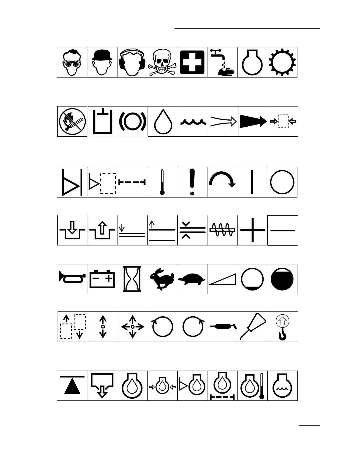
Symbol Glossary
Caustic liquids,
chemical burns to
fingers or hand
Crushing of
whole body,
applied from
above
Cutting or
entanglement of
foot, rotating auger
Poisonous
fumes or toxic
gases, asphyxiation
Crushing of
torso, force
applied from side
Severing of
foot, rotating
knives
Electrical shock,
electrocution
Crushing of fingers
or hand/, force
applied from side
Severing of
fingers or hand,
impeller blade
High pressure
fluid, injection
into body
force applied
from side
Wait until all
machine
components have
completely stopped
before touching them
High pressure
spray, erosion of
flesh
Crushing of
whole body
Severing of
fingers or hand,
engine fan
High pressure
spray, erosion of
flesh
Crushing of
head, torso and
arms
Whole body entanglement,
implement input drive line
Crushing of
fingers
or hand,
force
applied from
above
Cutting of
fingers or hand
Crushing of
toes or foot, force
applied from above
Cutting of footCrushing of leg,
Fingers or
hand entangle-
ment, chain drive
Hand & arm
entanglement,
belt drive
Explosion Fire or open
Shut off engine
& remove key before
performing mainten-
ance or repair work
6
Thrown or fly-
ing objects, whole
body exposure
flame
Riding on this
machine is allowed
only on a passen-
ger seat & only if the
driver’s view is not
hindered
Thrown or
flying objects,
face exposure
Secure lifting
cylinder with locking
device before getting
in hazardous area
Consult
technical manual
for proper service
procedures
Runover/back-
over, (relevant
machine to appear
in dashed box)
Stay a safe
distance from
the machine
Fasten seat belts Safety alert
Machine tipping,
riding mower
Stay clear of
articulation area
while engine is
running
Machine rollover,
ROPS (relevant
machine to appear
in dashed box)
triangle
Do not open
or remove safety
shields while
engine is
running
Stored energy
hazard, kickback
or upward motion
Do not step on
loading platform if
PTO is connected to tractor
& engine is running
outline safety
alert symbol
Hot surfaces,
burns to fingers
or hands
Do not step
Read operator’s
manual
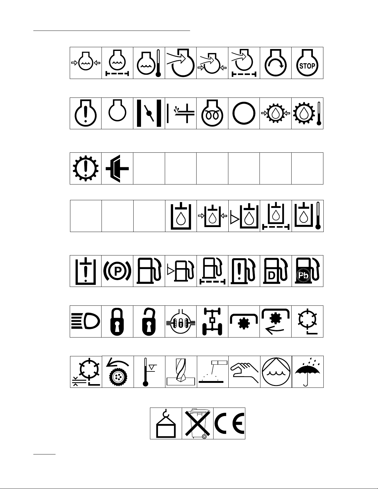
Page 7
Safety
Eye protection
must be worn
Fire, open light
& smoking
prohibited
Level
indicator
Head protection
must be worn
Hydraulic
system
Liquid level Filter Temperature Failure/
Hearing
protection must
be worn
Brake system
Caution, toxic
risk
Oil Coolant (water) Intake air Exhaust gas Pressure
First aid
Malfunction
Flush with water Engine Transmission
Start switch/
mechanism
On/start Off/stop
Engage Disengage
Horn Battery charging
Machine travel
direction,
forward/rearward
Jack or
support point
condition
Control lever
operating
direction, dual
direction
Draining/
emptying
Attachment
lower
Hourmeter/elapsed
operating hours
Control lever
operating
direction, multiple
direction
Engine lubricating oil
Attachment
raise
Fast Slow Continuous
Clockwise
rotation
Engine lubricating
oil pressure
Spacing distance Snow thrower,
Counter-clockwise rotation
Engine lubricating
oil level
collector auger
variable, linear
Grease
lubrication
point
Engine lubricating
oil filter
Plus/increase/
positive polarity
Volume empty Volume full
Oil lubrication
point
Engine
lubricating oil
temperature
Minus/decrease/
negative polarity
Lift point
Engine coolant
7
Page 8
Safety
Engine coolant
pressure
Engine coolant f
ilter
n/min
Engine failure/
malfunction
Transmission
failure/malfunction
Engine rotational
speed/frequency
Clutch Neutral High Low Forward Reverse Park
231
First gear Second gear
Engine
lubricating oil
pressure
Choke Primer (start aid) Electrical preheat
Engine intake/
combustion air
Engine intake/
combustion air
pressure
(low temperature
start aid)
Engine intake/
air filter
Transmission oil Transmission oil
Engine start Engine stop
pressure
Transmission oil
temperature
NHLFRP
Third gear (other #'s
may be used until
the maximum # of forward gears is reached.)
Hydraulic oil Hydraulic oil
Hydraulic oil
pressure
Hydraulic oil level Hydraulic oil filter
temperature
Hydraulic oil
failure/malfunction
Headlights Lock Unlock Differential lock 4-Wheel drive Power Take-Off Power Take-Off,
Reel cutting
element, height
adjustment
Parking brake Fuel Fuel level Fuel filter Fuel system
Traction Above working
temperature range
Drilling Manual metal arc
0430 weight Do not dispose
welding
in the garbage
failure/malfunction
Manual 0356 Water pump
CE logo
Diesel fuel Unleaded fuel
rotational speed
Reel cutting
element
0626 Keep dry
8
Page 9

Specifications
Engine: Peugeot, four-cycle, four cylinder, 1.9 liter
(1900 cc) displacement, liquid-cooled diesel engine.
23.5:1 compression ratio. Low idle—1600 rpm, high
idle—2500 rpm. Oil capacity is 5 l (5.3 qt) with the
filter.
Cooling System: Capacity is 13.2 l (3.5 gal) of a
50/50 mixture of Peugeot recommended anti-freeze.
Fuel System: Capacity is 53 l (14 gal) of #1 or #2
diesel fuel.
Hydraulic System: Reservoir capacity is 24.6 l (6.5
gal). Replaceable spin-on filter element.
Traction System: Ground speed: Low Range; 0—
10.5 km/h (0– 6.5 mph); 0–8.8 km/h (0–5.5 mph).
with mechanical speed limiter interlock forward and
0–4.8 km/h (0–3 mph) reverse. High Range; 0–24
km/h (0–15 mph); 0–20 km/h(0–12.4 mph) with
mechanical speed limiter interlock) forward and 0–8
km/h (0–5 mph) reverse.
Front Axle: Two-speed axle is designed to withstand
heavy-duty slope operation and side loading. Separate
mowing and transport selections for faster and more
efficient machine operation. Neutral position allows
easy towing. Lubricated with SAE 80—90 grade EP
gear lubrication. Capacity is 144 oz.
Rear Axles: T w o Wheel Drive—The large-diameter
wheel spindles are designed for durability and long
wear, yet provide superior stability and maneuverability. Four Wheel Drive—Heavy duty, agricultural type.
Hydraulic drive with “on demand” over running clutch
and balanced weight distribution provides superior
traction on hillsides. Lubricated with SAE 80—90 wt.
EP gear lubrication. Capacity is 80 oz.
Tires/Wheels: High flotation turf tread tires on demountable rims. Front tires: (2) 26 x 12.0-12, 8-ply.
Rear tires: (2) 20 x 10.0-10, 6 ply. Tire pressure
103–138 kPa (15-20 psi.)
Cutting Unit Drive System: Adjustable reel speed to
match clip to ground speed. Reel speed variable from
Approximately 500—1,200 rpm forward to 200—600
rpm reverse (for backlap operation).
Seat: (Model 30772) Adjustable fore and aft travel and
weight.
Diagnostic System: Test ports for forward traction,
cutting circuit, lift and counterbalance circuit, steering
circuit and charge circuit.
Steering System: Automotive type, full power.
Brakes: Totally enclosed, non asbestos, dry multi-
disc individual wheel and parking brakes on front traction wheels. Brakes controlled by individual pedals
operated by the left foot. Dynamic braking through a
closed-loop hydrostatic drive.
Electrical System: 12-volt battery with 530 coldcranking amps @ 0 degrees F. 55-amp alternator,
ammeter, starter, key switch and automatic temperature
controlled glow plug controller. Separately fused, run,
reel and instrument/accessory circuits.
Interlock System: Designed to stop the engine if the
operator gets off the seat while the cutting unit drive
switch is engaged. Prevents the engine from starting
unless the traction pedal is in neutral and the cutting
units are disengaged. Prevents the cutting units from
operating unless the axle shift is in the LO range and.
the cutting units are lowered. Prevents the engine
from starting unless the reel speed control is in
NEUTRAL.
Warning Lights:
Glow plug indicator
Engine oil pressure warning
Engine coolant temperature warning
Charge indicator
Indicators:
Engine coolant temperature gauge
Fuel gauge
Hour meter
9
Page 10

Specifications
GENERAL SPECIFICATIONS:
Width-of-Cut: 205 cm (81 in)
erall Width:
Ov
Cutting Units Raised. 165 cm (65 in)
Cutting Units Down 228 cm (90 in)
erall Length: 254 cm (100 in)
Ov
Height
: 147 cm (58 in)
With Roll Over Protection
System installed 208 cm (82 in)
Recommended Height-of-Cut:
5-Blade Cutting Unit: 2.54–10 cm (1–4 in)
7-Blade Cutting Unit: 1.27–5 cm (1/2–2 in)
11-Blade Cutting Unit: .95–1.9 cm (3/8–3/4 in)
W
heel Tread:
(Front). 132 cm (52 in)
(Rear) 111.8 cm (44 in)
W
heel Base: 132 cm (52 in)
y Weight:
Dr
2-Wheel Drive with 5-Blade Cutting Units &
skids = 980 kg (2,625 lbs)
2-Wheel Drive with 7- or 11-Blade Cutting Units
& rollers = 1092 kg (2,925 lbs)
4-Wheel Drive with 5-Blade Cutting Units &
skids = 1017 kg (2,725 lbs)
4-Wheel Drive with 7- or 11-Blade Cutting Units
& rollers = 1129 (3,025 lbs)
10
Page 11

Before Operating
CHECK THE ENGINE OIL
CAUTION
Before servicing or making adjustments to the
machine, stop the engine and remove the key from
the switch.
Crankcase capacity is 5.0 l (5.3 qt) with the filter.
1. Park the machine on a level surface. Release the
hood latch and open the hood.
Figure 1
1. Hood Latch
2. Remove the dipstick from the tube cap, wipe it
clean and reinstall it into the tube cap.. Pull it out
again and check the oil level on the dipstick: The
oil level must always be in the notch area on the
dipstick.
➀
Figure 2
1. Dipstick/Tub Cap
CHECK THE COOLING SYSTEM
Capacity of the system is 13.2 l (3.5 gal).
1. Park the machine on a level surface. Release the
hood latch and open the hood.
2. Check the coolant level. The coolant level should
be up to or above the mounting tabs on the tank,
when the engine is cold.
3. If coolant is low, remove the tank cap and add a
50/50 mixture of water and Peugeot-recommended anti-freeze. DO NOT USE WATER ONLY
OR ALCOHOL/ METHANOL BASE
COOLANTS.
➀
3. If the oil level is low, remove the tube cap and
add SAE 15W-40 CD oil until the level reaches
the top of notch on the dipstick. DO NOT
OVERFILL.
4. Install the oil tube cap.
5. Close the hood and secure the latch.
➁
➁
Figure 3
1. Degasser tank
2. Mounting tabs
11
Page 12

Before Operating
IMPORTANT: Do not remove the black plastic cap
on the tank.
DANGER
4. Install the tank cap.
5. Close the hood and secure the latch.
FILL THE FUEL T ANK
1. Park the machine on a level surface. Release the
hood latch and open the hood.
2. Remove the fuel tank cap.
➀
Because diesel fuel is highly flammable, use caution
when storing or handling it. Do not smoke while
filling the fuel tank. Do not fill the fuel tank while
the engine is running, hot, or when the machine is
in an enclosed area. Always fill the fuel tank outdoors and wipe up any spilled diesel fuel before
starting the engine. Store fuel in a clean, safetyapproved container and keep the cap in place. Use
diesel fuel for the engine only; not for any other
purpose.
Hydraulic Oil (Recommended brands):
Mobil DTE 26
Shell Tellus 68
Amoco Rykon Oil 68
Conoco Super Hydraulic Oil 68
Exxon Nuto 68
Kendall Kenoil R&O AW 68
Pennzoil Penreco 68
Phillips Magnus A 68
Standard Energol HLP 68
Sun Sunvis 831 WR
Union Unax A W 68
Chevron AW Hydraulic Oil 68
Figure 4
1. Fuel tank cap
3. Fill the tank to no more than one inch below the
bottom of the filler neck with No. 2 diesel fuel.
DO NOT OVER FILL. Then install the cap.
Note: For temperatures below 0° C (32° F), No 1
diesel fuel or a blend should be used.
4. Close the hood and secure the latch.
CHECK HYDRAULIC CIRCUIT OIL
The hydraulic system is designed to operate on Mobil
DTE 26 or equivalent anti-wear hydraulic fluid. The
machine’s reservoir is filled at the factory with 24.6 l
(6.5 gal) of fluid. However, check the level of
hydraulic fluid before the engine is first started and
daily thereafter.
Note: All are interchangeable.
IMPORTANT: Use only the hydraulic oils specified.
Other fluids could cause system damage.
Note: A red dye additive for the hydraulic system oil
is available in 2/3 oz. bottles. One bottle is sufficient
for 15–22.7 l (4–6 gal) of hydraulic oil. Order Part
No. 44-2500 from your Authorized Toro Distributor
1. Park the machine on a level surface. Make sure
the machine has been operated so the oil is warm.
Release the hood latch and open the hood. Check
the level of oil by viewing the sight gauge. If the
oil is visible in gauge, the oil level is sufficient.
2. If the oil level is not visible in gauge, remove the
cap from hydraulic oil reservoir and slowly fill
the reservoir with Mobil DTE 26 or equivalent
hydraulic oil until the level reaches middle (maximum) of the sight gauge. DO NOT OVERFILL.
12
Page 13

IMPORTANT: To prevent system contamination, clean the top of hydraulic oil containers
before puncturing them. Make sure the pour
spout and funnel are clean.
3. Install the reservoir cap, close the hood and
secure the latch.
➁
➀
Before Operating
➀
Figure 6
1. Access Panel
Figure 5
1. Sight gauge
2. Hydraulic reservoir cap
CHECK FRONT AXLE OIL LEVEL
The front axle is shipped from the factory filled with
SAE 80-90 grade gear lubricant. However, check the
level before the engine is first started and every 50
hours thereafter. Capacity is 128 oz.
1. Park the machine on a level surface.
2. Remove access panel (Fig. 6), in front of the seat,
to expose the front axle /dipstick.
3. Unscrew the dipstick cap (Fig. 7) from the filler
neck and wipe it with a clean rag. Screw the dipstick cap finger tight onto the filler neck.
Unscrew the dipstick and check the level of lubricant. If the level is not within 1/2 inch from the
groove in the dipstick, add enough to raise the
level to the groove mark. DO NOT OVERFILL
by more than 1.2 cm (1/2 in) above the groove.
Figure 7
1. Dipstick cap
4. Screw the dipstick filler cap finger-tight onto the
filler neck. It is not necessary to tighten the cap
with a wrench.
CHECK THE REAR AXLE LUBRICANT (Model 03603 Only) Fig. 8
The rear axle is shipped from the factory filled with
SAE 80-90 wt gear lubrication. However, check the
level before the engine is first started and every 50
hours thereafter. Capacity is 80 oz.
1. Position the machine on a level surface.
2. Remove a check plug from one end of the axle
13
Page 14

Before Operating
and make sure lubricant is up to the bottom of the
hole. If the level is low, remove the fill plug and
add enough lubricant to bring the level up to the
bottom of the check plug holes.
➁
➀
Figure 8
1. Check plug
2. Fill Plug
CHECK TIRE PRESSURE
CHECK TORQUE OF WHEEL
NUTS OR BOLTS
CHECK THE REEL-T O-BEDKNIFE
CONT ACT
Each day before operating, check the reel-to-bedknife
contact, regardless of whether or not quality of cut had
previously been acceptable. There must be light contact across the full length of the reel and bedknife.
WARNING
Torque the front wheel nuts to 61–75 Nm (45–55 ftlb) and the rear wheel nuts or bolts to 115–136 Nm
(85–100 ft lb) after 1–4 hours of operation and
again after 10 hours of operation and every 250
hours thereafter. Failure to maintain correct torque
could result in failure or loss of the wheel and may
result in personal injury.
The tires are over-inflated for shipping. Therefore,
release some of the air to reduce the pressure. Correct
air pressure in the front and rear tires is 103–138 kPa
(15–20 psi).
IMPORTANT: Maintain even pressure in all tires
to assure a good quality of cut and proper machine
performance. DO NOT UNDER INFLATE.
14
Page 15

Controls
Cutting Unit Engagement Switch (Fig 9)—Used
to start and stop cutting unit operation. Lift the switch
and move it forward to actuate the cutting units.
Glow Plug Indicator (Fig. 9)—Automatically actuates the proper glow period when the ignition key is
turned to the ON position. Illuminates when glow
plugs are actuated. When the glow plugs are heated
sufficiently, the light goes off indicating the engine is
ready to start.
Charge Indicator (Fig. 9)—Illuminates when the system charging circuit malfunctions.
Key Switch (Fig 9)—Three positions: OFF, ON and
START. Turn the key to START and release the key
when the engine begins running. To stop the engine,
turn the key to OFF.
Reel Speed Control (Fig 9)—Turn the knob clockwise to increase reel speed, counter-clockwise to
decrease speed or to backlap.
Throttle Control (Fig 9)—Move the control forward
to increase engine speed, backward to decrease it.
Cutting Unit Lift Controls (Fig 9)—The two outside
levers raise and lower the two outside the cutting units.
The center lever raises and lowers the center cutting
unit. The engine must be running to lower the cutting
units. When the cutting units are lifted, the reels automatically stop. To lower the cutting units just touch
levers momentarily. .
Coolant Temperature Gauge (Fig 9)—Shows temperature of engine coolant.
Fuel Gauge (Fig. 9)—Shows amount of fuel in the
tank.
Hour Meter (Fig. 9)—Shows the total hours the
machine has been operated.
Engine Oil Pressure Warning Light (Fig 9)—
Indicates dangerously low engine oil pressure.
Figure 9
1. Cutting unit engagement switch
2. Glow plug indicator
3. Charge indicator
4 Key Switch
5. Reel speed control
6. Throttle control
7. Cutting unit lift controls
8. Coolant temperature gauge
0. Fuel gauge
10. Hour meter
11. Engine oil pressure warning light
12. Engine coolant temperature warning light
Engine Coolant T emperature Warning Light (Fig.
9—The red light illuminates and the engine stops
when the coolant temperature exceeds 110° C (230°
F.)
Seat (Fig. 10)—The seat adjusting lever on left side of
the seat allows a 10 cm (4-in) fore and aft adjustment.
The seat adjusting knob on the front of the seat,
adjusts the seat for the operator’s weight.
Traction Pedal (Fig. 11)—Controls forward and
reverse operation. Depress the top of the pedal to
move forward and the bottom to move backward.
Ground speed depends on how far the pedal is
depressed. For no-load, maximum ground speed, fully
depress the pedal while the throttle is in FAST. For
maximum power under load or when going uphill,
keep engine rpm high by having the throttle in FAST
and the traction pedal partially engaged. If engine rpm
begins to decrease due to load, gradually reduce the
traction pedal pressure until the engine speed is
increased.
15
Page 16

Controls
To stop, reduce foot pressure on the traction pedal and
allow it to return to the center position. On extreme
downhill slopes, apply pressure to the REVERSE side
of the pedal, or operate with your heel on REVERSE
and your toe on the FORWARD portion of the pedal.
➁
Axle Shift Lever (Fig. 11)—Located on the right side
of the console, the lever selects the front drive mode.
Pull out the lockout knob and move the lever rearward
for mowing operation. Move it forward for transport
operation, then release the knob to lock your selection.
The middle position (N) is for towing.
CAUTION: The machine must be on a flat surface
with its brakes engaged when shifting the axle from
the HI to LO position.
➀
Figure 10
1. Seat adjusting lever
2. Seat adjusting knob
Speed Selector (Fig. 11)—The cam lever at the side
of the traction pedal can be rotated to maintain desired
speed. Rotating the lever forward decreases speed.
Rotating it backward increases speed.
➂
➃
➀
➁
➁
➂
➀
Figure 12
1. Brake pedals
2. Parking brake latch
3. Steering wheel tilt lever
Brake Pedals (Fig. 12)—Two foot pedals at the lower
left operate individual wheel brakes for turning assistance, parking and to aid in obtaining better sidehill
traction. The locking pin is for parking.
Parking Brake Latch (Fig. 12)—A knob on the left
side of the console actuates the parking brake lock. To
engage the parking brake, connect the pedals with the
locking pin, push down on both pedals and pull the
parking brake latch out. To release the parking brake,
depress both pedals until the parking brake latch
retracts.
1. Traction pedal
2. Speed Selector
3. Axle shift lever
4. Lockout knob
16
Figure 11
Steering Wheel Tilt Lever (Fig. 12)—This lever on
the left side of the console lets you adjust the steering
wheel for your comfort.
Transport Latches (Fig. 13)—Three latches secure
Page 17

Controls
the cutting units in the upright position for transport.
Horn—In the center of the steering wheel. Operates
only when the key switch is ON.
Figure 13
1. Transport latch (
3)
Operating Instructions
STARTING AND STOPPING
1. Sit on the seat, and keep your foot off the traction
pedal. Make sure the parking brake is engaged,
the traction pedal is in NEUTRAL and the cutting
unit engagement switch is in the DISENGAGED
position.
2. Turn the ignition switch to ON. When the glow
plug indicator light goes off, the engine is ready
to START.
3. Turn the ignition key to START. Release the key
when the engine starts.
4. To stop, disengage and move all controls to NEU-
TRAL and set the parking brake. Turn the key to
OFF and remove it from the switch. Raise and
latch all cutting units to the transport position.
PRIMING THE FUEL SYSTEM
(Fig. 14 & 15)
IMPORTANT: The fuel system may need to be
primed when a new engine is started for the first
time, if it runs out of fuel or if maintenance is performed on the fuel system.
1. Unlatch and raise the hood.
2. Insert a 3/16 inch hose over the bleed screw and
run the other end into a container to catch the
fuel.
3. Loosen the fuel filter/water separator bleed screw
(Fig. 14) a few turns. Pump the priming plunger
until a steady stream of fuel comes out of the
hole in the bleed screw. When the fuel stops
foaming, tighten the bleed screw during the
downstroke of the priming plunger. Wipe up any
spilled fuel.
17
Page 18

Operation
4. Pump the priming plunger until you feel resis-
tance. Try to start the engine. If the engine does
not start repeat step 3.
➀
➁
Figure 14
1. Primer plunger
2. Bleed screw
TRAL and the cutting unit engagement switch is DISENGAGED. In addition, the engine will stop when
the cutting unit engagement switch is engaged or the
traction pedal is depressed when the operator is off the
seat.
CAUTION
The interlock switches are for the operator’s protection, so do not disconnect them. Check operation of
the switches daily to assure the interlock system is
operating. If a switch is defective, replace it before
operating. Regardless of whether the switches are
operating correctly or not, replace them every two
years to assure maximum safety. Do not rely entirely on safety switches—use common sense.
1. In a wide open area free of debris and bystanders,
lower the cutting units to the ground. Stop the
engine.
2. Move the cutting unit engagement switch to DIS-
ENGAGED and remove your foot from the traction pedal.
Figure 15
1. Injection pump fitting
Note: It may be necessary to bleed the air out of the
fuel line between the fuel filter/water separator and the
injection pump. To do this, loosen the fitting on the
injection pump (Fig. 15) and repeat the bleeding procedure.
CHECKING THE INTERLOCK
SYSTEM.
The interlock system prevents the engine from cranking or starting unless the traction pedal is in NEU-
3. Turn the ignition key to START. The engine
should crank. If the engine cranks, go to step 4.
If the engine does not crank, there may be a malfunction in the interlock system.
4. Rise off the seat and engage the cutting unit
engagement switch while the engine is running.
The engine should stop within 2 seconds. If the
engine stops, the switch is operating correctly;
thus, go to step 5. If the engine does not stop,
there is a malfunction in the interlock system.
5. Rise off the seat and depress the traction pedal
while the engine is running and the cutting unit
engagement switch is DISENGAGED. The
engine should stop within 2 seconds. If the
engine stops, the switch is operating correctly;
thus, continue operation. If the engine does not
stop, there is a malfunction in the interlock system.
18
Page 19

Operating
OPERATING CHARACTERISTICS
Familiarization—Before mowing grass, practice operating the machine in an open area. Start and stop the
engine. Operate in forward and reverse. Lower and
raise the cutting units simultaneously and individually.
Engage and disengage the reels. Operate with all cutting units down, then with only an individual cutting
unit. When you feel familiar with the machine, practice operating around trees and obstacles. Also drive
up and down slopes at different speeds.
WARNING: When operating a 4-wheel drive
machine, always use the seat belt and roll over protection system together and have the seat pivot retaining
pin installed.
Another characteristic to consider is brake pedal operation. The brakes can be used to help turn the
machine. However, use them carefully, especially on
soft or wet grass because the turf may be torn accidentally. Another benefit of the brakes is to maintain traction. For example: Suppose when operating on a sidehill, the uphill wheel slips and loses traction. If this
occurs, depress the uphill brake pedal gradually and
intermittently until the uphill wheel stops slipping,
thus, increasing traction on the downhill wheel.
CAUTION: This product may exceed noise levels of
85 dB(A) at the operator position. Ear protectors are
recommended, for prolonged exposure, to reduce the
potential of permanent hearing damage.
Warning System—If a warning light comes on during
operation, stop the machine immediately and correct
the problem before continuing operation. Serious
damage could occur if the machine is operated with a
malfunction.
pulling back on the lift control levers. Hold the levers
back until the cutting units are fully raised. Lock the
cutting units in place with the transport latches. Move
the axle shift lever forward to the HI position. When
driving from one area to another, always shift the axle
to the LO position before encountering a slope. Never
shift from HI to LO while on a slope. Stop the
machine on a flat surface, engage the brakes and shift
before climbing the slope. Be careful when driving
between objects so you do not accidentally damage the
machine or the cutting units. Use extra care when
operating the machine on slopes. Drive slowly and
avoid sharp turns on slopes to prevent rollovers. The
cutting units must be lowered when going downhill for
steering control.
Pushing Or Towing The traction Unit—Use only a
rigid tow bar if it is necessary to tow the machine.
Make sure the axle shift lever is in NEUTRAL and
only tow the machine forward. Use a trailer for normal transport. Move the axle shift lever to LO before
loading the machine on a trailer.
Matching Ground Speed and Reel Speed—Vary reel
speed (while maintaining constant ground speed) to
establish the best quality of cut for the area being
mowed. Reel speeds either too fast or too slow for
conditions may effect the quality of cut. See clip chart
(Fig. 17) to determine approximate settings for reel
speed and ground speed.
Note: To lock the reel speed setting so it cannot be
changed while operating the machine, tighten the capscrew on the reel speed shaft. (Fig. 16).
Mowing—When you are at the area to be mowed,
release the cutting unit transport latches. Start the
engine, move axle shift lever rearward to the MOW
position and move the throttle to FAST so the engine
is running at maximum speed. To move forward and
cut grass, press the traction pedal forward. Maintain
traction pedal contact with the speed selector to assure
a consistent clip and quality of cut.
Transport—After mowing, raise the cutting units by
Figure 16
1. Reel speed locking capscrew
19
Page 20

Operating
CUTTING CHARTS
Relate height of cut and ground speed to required reel speed setting on reel speed knob
Note: 1 = 500 rpm; 2 = 700 rpm; 3 = 900 rpm; 4 = 1,200 rpm
Recommended Reel Speed Settings
5-Blade Reel
Ground Speed in KM/H
6 8
5
1
25
31
38
50
63
1
2
1
1
10
2 2
4
2
1
11
3 3
4
3
1 1
8-Blade Reel
Ground Speed in KM/H
6 8
5
13
16
3
19
2
25
31
3
2
4
3 2
4
2
3
1
2
2
1
Figure 17
10
11
4
3
3
3
3
11-Blade Reel
Ground Speed in KM/H
6 8
5
10
13
16
19
3
2
1
2
1
1
1
10
4
3
2 2 3
1
11
4
4
4
3
20
Page 21

Service Interval —2-Wheel Drive
Maintenance
CHECK/SERVICE
1. Engine oil level/fill 7. Grease Points (22)
2. Hydraulic oil level/fill 8. Radiator screen
3. Front axle oil level/fill 9. Air cleaner
4. Fan belt 10. Water separator/fuel filter
5. Fan belt 10. Water separator/fuel filter
6 Fuel—Diesel only 12. Tire pressure (1–1.5 bar/15-20 psi)
FLUID SPECIFICATIONS/CHANGE INTERVALS
Change Intervals Filter
Fluid Type Capacity Fluid Filter Part No.
Engine Oil SAE 15W-40 CD 5 L 50 hours 100 hours 74-7970A
Hydraulic Oil Mobil DTE 26 24.6 L 500 hours 500 hours 86-3010B
Axle Oil SAE 80-90 E.P. 750 hours
Fuel Filter 400 hours 76-5220C
Air Cleaner Clean @ 50 hours 250 hours 27-7110D
Fuel >0° C No. 2-D 53 L
<0° C No. 1.-D
Coolant 50/50 Peugeot
recommended antifreeze
13.25 L
Drain and flush, 2 years
21
Page 22

Maintenance
Service Interval —4-Wheel Drive
CHECK/SERVICE
1. Engine oil level/fill 7. Grease Points (22)
2. Hydraulic oil level/fill 8. Radiator screen
3. Front axle oil level/fill 9. Air cleaner
4. Rear axle oil 10. Water separator/fuel filter
A. Fill 11. Battery
B. Check (2) 12. Fan belt
5. Coolant level/fill 13. Tire pressure
6. Fuel—Diesel only (1–1.5 bar/15-20 psi)
Change Intervals Filter
Fluid Type Capacity Fluid Filter Part No.
Engine Oil SAE 15W-40 CD 5 L 50 hours 100 hours 74-7970A
Hydraulic Oil Mobil DTE 26 24.6 L 500 hours 500 hours 86-3010B
Axle Oil SAE 80-90 E.P. 750 hours
Fuel Filter 400 hours 76-5220C
Air Cleaner Clean @ 50 hours 250 hours 27-7110D
Fuel >0° C No. 2-D 53 L
<0° C No. 1.-D
Coolant 50/50 Peugeot
recommended antifreeze
13.25 L
Drain and flush, 2 years
22
Page 23

LUBRICATION
GREASING BEARINGS AND BUSHINGS
(Fig. 28-38)
The traction unit has grease fittings that must be lubricated regularly with No. 2 General Purpose Lithium
Base Grease. If you operate the machine under normal
conditions, lubricate all bearings and bushings after
every 25 hours of operation.
1. The traction unit bearings and bushings that must
be lubricated are:
wo- and Four-wheel drive the machines— #1
T
Lift arm pivot (1), #1 lift cylinder (1), brake arm
pivots (2) (Fig. 18); #2 & 3 lift arm pivots (2), #2
& #3 lift cylinders (2), brake pivot (1) (Fig. 19);
brake pivots (2) (Fig. 20); traction pedal pivot (1)
(Fig. 21); reel speed shaft (1) (Fig. 22); traction
adjuster (1) (Fig. 23) and the transmission shift
linkage (1) (Fig. 28)
wo-wheel drive machines—cylinder end (2), tie
T
rod assembly (2) (Fig. 24); center pivot (1), spindles (2) (Fig. 25).
our-wheel drive machines—tie rod assemblies
F
(2), center pivot (1), axle knuckles (2) (Fig. 26);
cylinder ends (2) (Fig. 27).
Maintenance
Figure 19
Figure 20
1. Wipe the grease fitting clean so foreign matter
cannot be forced into the bearing or bushing.
2. Pump grease into the bearing or bushing.
3. Wipe up excess grease.
Figure 18
Figure 21
23
Page 24

Maintenance
Figure 25
Figure 22
Figure 23
Figure 24
Figure 26
Figure 27
24
Page 25

Maintenance
1. Thumb Screw
2. Dust cup
3. Baffle
4. Wing nut & gasket
5. Filter element
6. Air cleaner body
Figure 28
Figure 29
Figure 31
1. Oil filter
Figure 32
1. Fuel filter/water separator
2. Drain screw
3. Primer plunger
1. Drain plug
Figure 30
Figure 33
1. Rear screen
25
Page 26

Maintenance
➀
1. Oil cooler
1. Fan belt
2. Adjusting screw
Figure 34
Figure 35
Figure 37
1. Sight gauge
➀
Figure 38
1. Hydraulic filter
Figure 35
1. Hydraulic reservoir drain plugs
26
Figure 39
1. Front axle drain plug
Page 27

Figure 40
1. Drain plugs (2)
Maintenance
➀
27
Page 28

Preparation For Seasonal Storage
Traction Unit
1. Thoroughly clean the traction unit, cutting units
and the engine.
2. Check the tire pressure. Inflate all tires to
103–138 kPa (15–20 psi)
3. Check all fasteners for looseness; tighten as nec-
essary.
4. Grease or oil all grease fittings and pivot points.
Wipe up any excess lubricant.
5. Lightly sand and use touch-up paint on painted
areas that are scratched, chipped, or rusted.
Repair any dents in the metal body.
6. Service the battery and cables as follows:
a. Remove the battery terminals from the battery
posts.
4. Start the engine and run at idle speed for approxi-
mately two minutes.
5. Stop the engine.
6. Thoroughly drain all fuel from the fuel tank, lines
and the fuel filter/water separator assembly.
7. Flush the fuel tank with fresh, clean diesel fuel.
8. Secure all fuel system fittings.
9. Thoroughly clean and service the air cleaner
assembly.
10. Seal the air cleaner inlet and the exhaust outlet
with weatherproof tape.
11. Check anti-freeze protection and add a 50/50
solution of water and Peugeot recommended antifreeze as needed for expected minimum temperature in your area.
b. Clean the battery, terminals, and posts with a
wire brush and baking soda solution.
c. Coat the cable terminals and battery posts
with Grafo 112X skin-over grease (Toro Part
No. 505-47) or petroleum jelly to prevent corrosion.
d. Slowly recharge the battery every 60 days for
24 hours to prevent lead sulfation of the battery.
Engine
1. Drain the engine oil from the oil pan and replace
the drain plug.
2. Remove and discard the oil filter. Install a new
oil filter.
3. Refill the oil pan with 5 l (5.3 qt) of SAE 15W—
40 CD motor oil.
Product Identification
MODEL AND SERIAL NUMBER
The model and serial number is on a plate that is
mounted on the left front frame member. Use model
and serial number in all correspondence and when
ordering parts.
28
 Loading...