

Toro 03550 Reelmaster 5500-D, 03551 Reelmaster 5500-D, 03550, 03551, Reelmaster 5500–D Operator's Manual
Page 1

Form No. 3354–505 Rev A
Reelmaster
5500–D
2 and 4 Wheel Drive Traction Units
Model No. 03550—260000001 and Up
Model No. 03551—260000001 and Up
Operator’s Manual
English (EN, GB)
Page 2

Warning
CALIFORNIA
Proposition 65 Warning
Diesel engine exhaust and some of its constituents
are known to the State of California to cause
cancer, birth defects, and other reproductive harm.
Important The engine in this product is not equipped
with a spark arrester muffler. It is a violation of California
Public Resource Code Section 4442 to use or operate this
engine on any forest-covered, brush-covered, or
grass-covered land as defined in CPRC 4126. Other states
or federal areas may have similar laws.
Contents
Page
Introduction 3. . . . . . . . . . . . . . . . . . . . . . . . . . . . . . . . .
Safety 3. . . . . . . . . . . . . . . . . . . . . . . . . . . . . . . . . . . . . .
Safe Operating Practices 3. . . . . . . . . . . . . . . . . . . .
Toro Riding Mower Safety 5. . . . . . . . . . . . . . . . . . .
Sound Pressure Level 6. . . . . . . . . . . . . . . . . . . . . . .
Vibration Level 6. . . . . . . . . . . . . . . . . . . . . . . . . . . .
Safety and Instruction Decals 7. . . . . . . . . . . . . . . . .
General Specifications 12. . . . . . . . . . . . . . . . . . . . .
Measurements 13. . . . . . . . . . . . . . . . . . . . . . . . . . . .
Optional Equipment 13. . . . . . . . . . . . . . . . . . . . . . . .
Setup 14. . . . . . . . . . . . . . . . . . . . . . . . . . . . . . . . . . . . . .
Connecting the Battery 15. . . . . . . . . . . . . . . . . . . . . .
Mounting the Hood Latch 16. . . . . . . . . . . . . . . . . . .
Replacing the Floor Panel Fastener 16. . . . . . . . . . .
Checking the Tire Pressure 16. . . . . . . . . . . . . . . . . .
Installing the Cutting Units 16. . . . . . . . . . . . . . . . . .
Alternate the Adjustments 18. . . . . . . . . . . . . . . . . . .
Adjusting the Cutting Unit Stabilizer 19. . . . . . . . . . .
Rear Ballast 19. . . . . . . . . . . . . . . . . . . . . . . . . . . . . .
Before Operating 20. . . . . . . . . . . . . . . . . . . . . . . . . . . . .
Checking the Engine Oil 20. . . . . . . . . . . . . . . . . . . .
Checking the Cooling System 20. . . . . . . . . . . . . . . .
Filling the Fuel Tank 21. . . . . . . . . . . . . . . . . . . . . . .
Checking the Transmission Fluid 21. . . . . . . . . . . . . .
Checking the Hydraulic Fluid 21. . . . . . . . . . . . . . . .
Checking the Rear Axle Lubricant 22. . . . . . . . . . . .
Checking the Reel to Bedknife Contact 22. . . . . . . . .
Check the Torque of the Wheel Nuts 22. . . . . . . . . . .
Operation 23. . . . . . . . . . . . . . . . . . . . . . . . . . . . . . . . . . .
Controls 23. . . . . . . . . . . . . . . . . . . . . . . . . . . . . . . . .
Starting and Stopping 25. . . . . . . . . . . . . . . . . . . . . . .
Bleeding the Fuel System 25. . . . . . . . . . . . . . . . . . . .
Setting the Reel Speed 25. . . . . . . . . . . . . . . . . . . . . .
Adjusting the Rear Lift Arm Counterbalance 26. . . .
Towing the Traction Unit 27. . . . . . . . . . . . . . . . . . . .
Diagnostic Light 27. . . . . . . . . . . . . . . . . . . . . . . . . . .
Diagnostic ACE Display 28. . . . . . . . . . . . . . . . . . . .
Checking the Interlock Switches 28. . . . . . . . . . . . . .
Hydraulic Valve Solenoid Functions 29. . . . . . . . . . .
Operating Characteristics 30. . . . . . . . . . . . . . . . . . . .
Maintenance 31. . . . . . . . . . . . . . . . . . . . . . . . . . . . . . . . .
Recommended Maintenance Schedule 31. . . . . . . . .
Lubricating the Mower 32. . . . . . . . . . . . . . . . . . . . . .
Service Interval Chart 34. . . . . . . . . . . . . . . . . . . . . .
Daily Maintenance Checklist 35. . . . . . . . . . . . . . . . .
Servicing the Air Cleaner 35. . . . . . . . . . . . . . . . . . . .
Servicing the Engine Oil and Filter 36. . . . . . . . . . . .
Servicing the Fuel System 37. . . . . . . . . . . . . . . . . . .
Replacing the Fuel Pre Filter 37. . . . . . . . . . . . . . . . .
Bleeding Air from the Injectors 38. . . . . . . . . . . . . . .
Servicing the Engine Cooling System 38. . . . . . . . . .
Servicing the Engine Belts 39. . . . . . . . . . . . . . . . . . .
Adjusting the Throttle 40. . . . . . . . . . . . . . . . . . . . . .
Changing the Hydraulic Fluid 40. . . . . . . . . . . . . . . .
Replacing the Hydraulic Filter 40. . . . . . . . . . . . . . . .
Checking Hydraulic Lines And Hoses 41. . . . . . . . . .
Using the Hydraulic System Test Ports 41. . . . . . . . .
Adjusting Traction Drive For Neutral 41. . . . . . . . . .
Adjusting the Cutting Unit Drop Rate 42. . . . . . . . . .
Checking and Adjusting Traction Linkage 43. . . . . .
Hydraulic Schematic 44. . . . . . . . . . . . . . . . . . . . . . .
Adjusting the Service Brakes 45. . . . . . . . . . . . . . . . .
Changing the Transmission Fluid 45. . . . . . . . . . . . .
Replacing the Transmission Filter 45. . . . . . . . . . . . .
Changing Rear Axle Lubricant 46. . . . . . . . . . . . . . .
Checking and Adjusting the Rear Wheel Toe–In 46. .
Servicing the Battery 46. . . . . . . . . . . . . . . . . . . . . . .
Servicing the Fuses 47. . . . . . . . . . . . . . . . . . . . . . . .
Adjusting the Parking Brake Switch 47. . . . . . . . . . .
Installing Optional Lighting 47. . . . . . . . . . . . . . . . . .
Wiring Diagram 48. . . . . . . . . . . . . . . . . . . . . . . . . . .
Backlapping 49. . . . . . . . . . . . . . . . . . . . . . . . . . . . . .
Maintaining the Cutting Unit 50. . . . . . . . . . . . . . . . .
Storage 51. . . . . . . . . . . . . . . . . . . . . . . . . . . . . . . . . . . . .
Traction Unit 51. . . . . . . . . . . . . . . . . . . . . . . . . . . . .
Engine 51. . . . . . . . . . . . . . . . . . . . . . . . . . . . . . . . . .
The Toro General Commercial Products Warranty 52. . .
2005 by The Toro Company
8111 Lyndale Avenue South
Bloomington, MN 55420-1196
All Rights Reserved
Printed in the USA
2
Page 3

Introduction
Read this manual carefully to learn how to operate and
maintain your product properly. The information in this
manual can help you and others avoid injury and product
damage. Although Toro designs and produces safe
products, you are responsible for operating the product
properly and safely.
Whenever you need service, genuine Toro parts, or
additional information, contact an Authorized Service
Dealer or Toro Customer Service and have the model and
serial numbers of your product ready. Figure 1 illustrates
the location of the model and serial numbers on the
product.
1
Figure 1
1. Location of the model and serial numbers
This manual uses two other words to highlight information.
Important calls attention to special mechanical
information and Note: emphasizes general information
worthy of special attention.
Safety
This machine meets or exceeds CEN standard EN
836:1997, ISO standard 5395:1990, and ANSI
B71.4-1999 specifications in effect at the time of
production when 40 lb. (18 kg) of ballast is added to the
rear wheel.
Improper use or maintenance by the operator or owner
can result in injury. To reduce the potential for injury,
comply with these safety instructions and always pay
attention to the safety alert
CAUTION, WARNING, or DANGER—“personal
safety instruction.” Failure to comply with the
instruction may result in personal injury or death.
Safe Operating Practices
The following instructions are from the CEN standard EN
836:1997, ISO standard 5395:1990, and ANSI B71.4-1999.
Training
symbol, which means
Write the product model and serial numbers in the space
below:
Model No.
Serial No.
This manual identifies potential hazards and has special
safety messages that help you and others avoid personal
injury and even death. Danger, Warning, and Caution are
signal words used to identify the level of hazard. However,
regardless of the hazard, be extremely careful.
Danger signals an extreme hazard that will cause serious
injury or death if you do not follow the recommended
precautions.
Warning signals a hazard that may cause serious injury or
death if you do not follow the recommended precautions.
Caution signals a hazard that may cause minor or moderate
injury if you do not follow the recommended precautions.
• Read the operator’s manual and other training material
carefully. Be familiar with the controls, safety signs,
and the proper use of the equipment.
• Never allow children or people unfamiliar with these
instructions to use or service the mower. Local
regulations may restrict the age of the operator.
• Never mow while people, especially children, or pets
are nearby.
• Keep in mind that the operator or user is responsible for
accidents or hazards occurring to other people or their
property.
• Do not carry passengers.
• All drivers and mechanics should seek and obtain
professional and practical instruction. The owner is
responsible for training the users. Such instruction
should emphasize:
– the need for care and concentration when working
with ride-on machines;
– control of a ride-on machine sliding on a slope will
not be regained by the application of the brake. The
main reasons for loss of control are:
• insufficient wheel grip;
3
Page 4

• being driven too fast;
• inadequate braking;
• the type of machine is unsuitable for its task;
• lack of awareness of the effect of ground
conditions, especially slopes;
• incorrect hitching and load distribution.
• The owner/user can prevent and is responsible for
accidents or injuries occurring to himself or herself,
other people, or property.
Preparation
• While mowing, always wear substantial footwear, long
trousers, hard hat, safety glasses, and ear protection.
Long hair, loose clothing, or jewelry may get tangled in
moving parts. Do not operate the equipment when
barefoot or wearing open sandals.
• Thoroughly inspect the area where the equipment is to
be used and remove all objects which may be thrown by
the machine.
• Warning—Fuel is highly flammable. Take the
following precautions:
– Store fuel in containers specifically designed for this
purpose.
– Refuel outdoors only and do not smoke while
refuelling.
– Add fuel before starting the engine. Never remove
the cap of the fuel tank or add fuel while the engine
is running or when the engine is hot.
– If fuel is spilled, do not attempt to start the engine
but move the machine away from the area of
spillage and avoid creating any source of ignition
until fuel vapors have dissipated.
– Replace all fuel tanks and container caps securely.
• Replace faulty silencers/mufflers.
• Evaluate the terrain to determine what accessories and
attachments are needed to properly and safely perform
the job. Only use accessories and attachments approved
by the manufacturer.
• Check that operator’s presence controls, safety switches
and shields are attached and functioning properly. Do
not operate unless they are functioning properly.
Operation
• Do not operate the engine in a confined space where
dangerous carbon monoxide fumes can collect.
• Mow only in daylight or in good artificial light.
• Before attempting to start the engine, disengage all
blade attachment clutches, shift into neutral, and engage
the parking brake.
• Remember there is no such thing as a safe slope. Travel
on grass slopes requires particular care. To guard
against overturning:
– do not stop or start suddenly when going up or
downhill;
– engage clutch slowly, always keep machine in gear,
especially when travelling downhill;
– machine speeds should be kept low on slopes and
during tight turns;
– stay alert for humps and hollows and other hidden
hazards;
– never mow across the face of the slope, unless the
mower is designed for this purpose.
• Stay alert for holes in the terrain and other hidden
hazards.
• Use care when pulling loads or using heavy equipment.
– Use only approved drawbar hitch points.
– Limit loads to those you can safely control.
– Do not turn sharply. Use care when reversing.
– Use counterweight(s) or wheel weights when
suggested in the operator’s manual.
• Watch out for traffic when crossing or near roadways.
• Stop the blades rotating before crossing surfaces other
than grass.
• When using any attachments, never direct discharge of
material toward bystanders nor allow anyone near the
machine while in operation.
• Never operate the machine with damaged guards,
shields, or without safety protective devices in place. Be
sure all interlocks are attached, adjusted properly, and
functioning properly.
• Do not change the engine governor settings or
overspeed the engine. Operating the engine at excessive
speed may increase the hazard of personal injury.
• Before leaving the operator’s position:
– stop on level ground;
– disengage the power take-off and lower the
attachments;
– change into neutral and set the parking brake;
– stop the engine and remove the key.
• Disengage drive to attachments when transporting or
not in use.
4
Page 5

• Stop the engine and disengage drive to attachment
– before refuelling;
– before removing the grass catcher/catchers;
– before making height adjustment unless adjustment
can be made from the operator’s position.
– before clearing blockages;
– before checking, cleaning or working on the mower;
– after striking a foreign object or if an abnormal
vibration occurs. Inspect the mower for damage and
make repairs before restarting and operating the
equipment.
• Be careful during adjustment of the machine to prevent
entrapment of the fingers between moving blades and
fixed parts of the machine.
• On multi-cylinder/multi-reel machines, take care as
rotating one cylinder/reel can cause other
cylinders/reels to rotate.
• Disengage drives, lower the cutting units, set parking
brake, stop engine and remove key and disconnect spark
plug wire. Wait for all movement to stop before
adjusting, cleaning or repairing.
• Clean grass and debris from cutting units, drives,
silencers/mufflers, and engine to help prevent fires.
Clean up oil or fuel spillage.
• Reduce the throttle setting during engine run-out and, if
the engine is provided with a shut-off valve, turn the
fuel off at the conclusion of mowing.
• Keep hands and feet away from the cutting units.
• Look behind and down before backing up to be sure of
a clear path.
• Slow down and use caution when making turns and
crossing roads and sidewalks. Stop cylinders/reels if not
mowing.
• Do not operate the mower under the influence of
alcohol or drugs
• Use care when loading or unloading the machine into a
trailer or truck
• Use care when approaching blind corners, shrubs, trees,
or other objects that may obscure vision.
Maintenance and Storage
• Keep all nuts, bolts and screws tight to be sure the
equipment is in safe working condition.
• Never store the equipment with fuel in the tank inside a
building where fumes may reach an open flame or
spark.
• Allow the engine to cool before storing in any
enclosure.
• To reduce the fire hazard, keep the engine,
silencer/muffler, battery compartment and fuel storage
area free of grass, leaves, or excessive grease.
• Use jack stands to support components when required.
• Carefully release pressure from components with stored
energy.
• Disconnect battery and remove spark plug wire before
making any repairs. Disconnect the negative terminal
first and the positive last. Reconnect positive first and
negative last.
• Use care when checking the cylinders/reels. Wear
gloves and use caution when servicing them.
• Keep hands and feet away from moving parts. If
possible, do not make adjustments with the engine
running.
• Charge batteries in an open well ventilated area, away
from spark and flames. Unplug charger before
connecting or disconnecting from battery. Wear
protective clothing and use insulated tools.
Toro Riding Mower Safety
The following list contains safety information specific to
Toro products or other safety information that you must
know that is not included in the CEN, ISO, or ANSI
standard.
This product is capable of amputating hands and feet and
throwing objects. Always follow all safety instructions to
avoid serious injury or death.
Use of this product for purposes other than its intended use
could prove dangerous to user and bystanders.
• Check the grass catcher frequently for wear or
deterioration.
• Keep all parts in good working condition and all
hardware and hydraulic fittings tightened. Replace all
worn or damaged parts and decals.
• If the fuel tank has to be drained, do this outdoors.
Warning
Engine exhaust contains carbon monoxide, which
is an odorless, deadly poison that can kill you.
Do not run engine indoors or in an enclosed area.
• Know how to stop the engine quickly.
5
Page 6

• Do not operate the machine while wearing tennis shoes
or sneakers.
• Wearing safety shoes and long pants is advisable and
required by some local ordinances and insurance
regulations.
• Handle fuel carefully. Wipe up any spills.
• Check the safety interlock switches daily for proper
operation. If a switch should fail, replace the switch
before operating the machine. After every two years,
replace all four interlock switches in the safety system,
whether they are working properly or not.
• Before starting the engine, sit on the seat.
• Using the machine demands attention. To prevent loss
of control:
Maintenance and Storage
• Make sure all hydraulic line connectors are tight and all
hydraulic hoses and lines are in good condition before
applying pressure to the system.
• Keep your body and hands away from pin hole leaks or
nozzles that eject hydraulic fluid under high pressure.
Use paper or cardboard, not your hands, to search for
leaks. Hydraulic fluid escaping under pressure can have
sufficient force to penetrate the skin and cause serious
injury. Seek immediate medical attention if fluid is
injected into skin.
• Before disconnecting or performing any work on the
hydraulic system, all pressure in the system must be
relieved by stopping the engine and lowering the cutting
units and attachments to the ground.
– Do not drive close to sand traps, ditches, creeks, or
other hazards.
– Reduce speed when making sharp turns. Avoid
sudden stops and starts.
– When near or crossing roads, always yield the
right-of-way.
– Apply the service brakes when going downhill to
keep forward speed slow and to maintain control of
the machine.
• The grass baskets must be in place during operation of
the cylinders/reels or thatchers for maximum safety.
Shut the engine off before emptying the baskets.
• Raise the cutting units when driving from one work
area to another.
• Do not touch the engine, silencer/muffler, or exhaust
pipe while the engine is running or soon after it has
stopped because these areas could be hot enough to
cause burns.
• Stay clear of the rotating screen at the side of the engine
to prevent direct contact with your body or clothing.
• If the engine stalls or loses headway and cannot make it
to the top of a slope, do not turn the machine around.
Always back slowly, straight down the slope.
• When a person or pet appears unexpectedly in or near
the mowing area, stop mowing. Careless operation,
combined with terrain angles, ricochets, or improperly
positioned guards can lead to thrown object injuries. Do
not resume mowing until the area is cleared.
• Check all fuel lines for tightness and wear on a regular
basis. Tighten or repair them as needed.
• If the engine must be running to perform a maintenance
adjustment, keep hands, feet, clothing, and any parts of
the body away from the cutting units, attachments, and
any moving parts, especially the screen at the side of the
engine. Keep everyone away.
• To ensure safety and accuracy, have an Authorized Toro
Distributor check the maximum engine speed with a
tachometer. Maximum governed engine speed should be
2900 RPM.
• If major repairs are ever needed or if assistance is
desired, contact an Authorized Toro Distributor.
• Use only Toro-approved attachments and replacement
parts. The warranty may be voided if used with
unapproved attachments.
Sound Pressure Level
This unit has an equivalent continuous A–weighted sound
pressure level at the operator ear of 82 dBA, based on
measurements of identical machines per Directive
98/37/EC and amendments.
Vibration Level
This unit does not exceed a vibration level of 2.5 m/s@ at
the hands based on measurements of identical machines per
ISO 5349 procedures.
This unit does not exceed a vibration level of 0.5 m/s@ at
the posterior based on measurements of identical machines
per ISO 2631 procedures.
6
Page 7
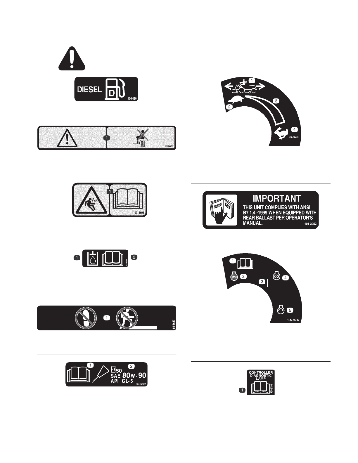
Safety and Instruction Decals
Safety decals and instructions are easily visible to the operator and are located near any area
of potential danger. Replace any decal that is damaged or lost.
93-6680
93-6689
1. Warning—do not carry passengers.
93-6696
1. Stored energy hazard—read the Operator’s Manual.
93-6686
1. Hydraulic oil 2. Read the Operator’s
Manual.
1. Machine speed
2. Slow
93-6699
3. Continuous variable
setting
4. Fast
104-2052
1. Do not step here.
(Model 03551 only)
1. Read the Operator’s
Manual.
93-6687
93-6697
2. Add SAE 80w–90 (API
GL-5) oil every 50 hours.
1. Read the Operator’s
Manual
2. Engine—stop
1. Read the Operator’s Manual.
7
105-7506
3. On
4. Engine—preheat
5. Engine—start
104-9298
Page 8
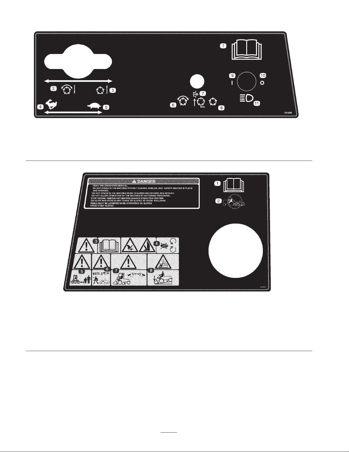
1. Read the Operator’s Manual.
2. Lower and engage the reels.
3. Raise and disengage the
reels.
4. Fast
5. Slow
6. Enable the reels
104-9296
7. Disable and raise the reels
8. Disable the reels
9. On
10. Off
11. Headlights
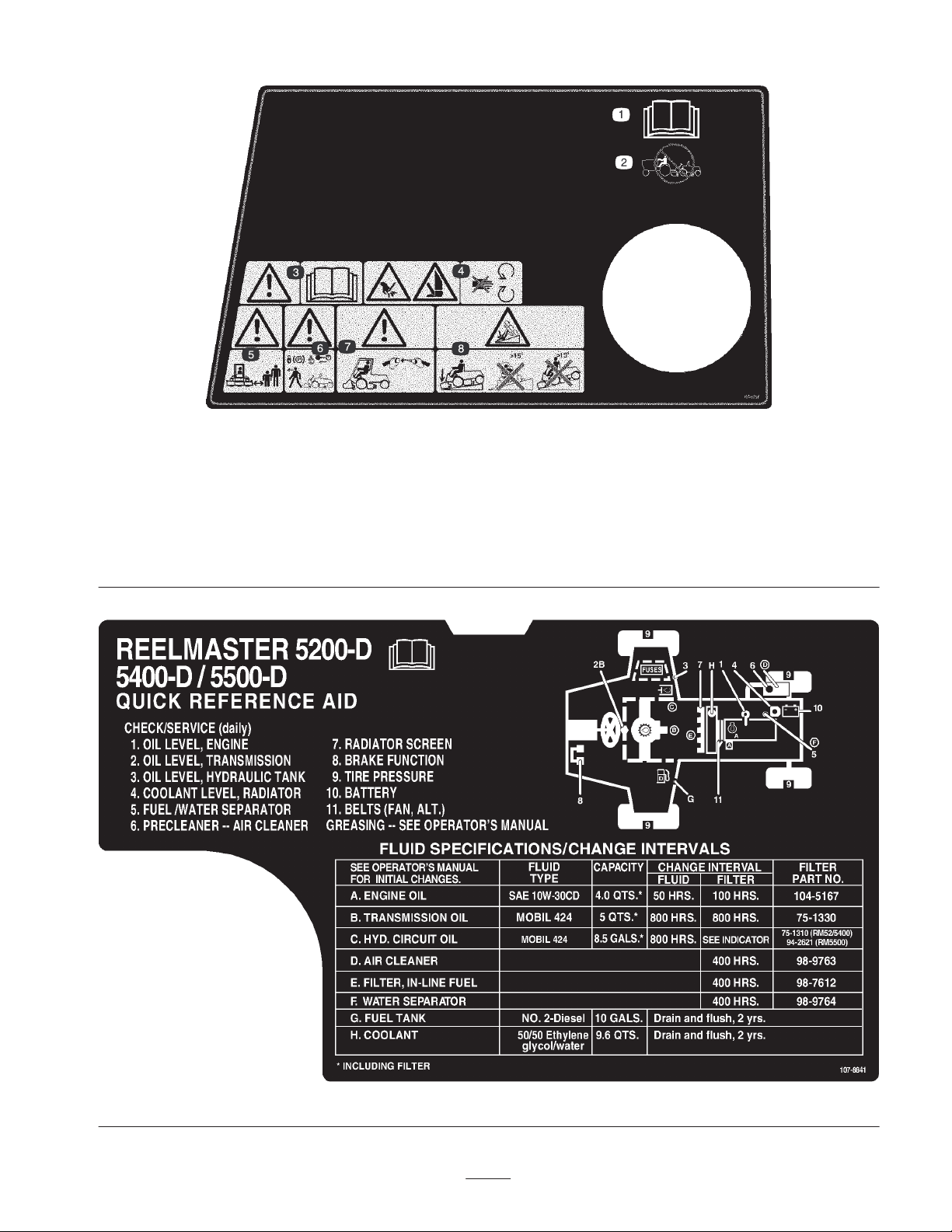
1. Read the Operator’s Manual.
2. Do not tow the machine.
3. Warning—read the
Operator’s Manual.
4. Cutting hazard of hand or
foot—stay away from
moving parts.
104-9294
5. Warning—keep bystanders
a safe distance from the
machine.
6. Warning—lock the parking
brake, stop the engine, and
remove the ignition key
before leaving the machine.
7. Warning—use a roll over
protection system and wear
the seat belt.
8
8. Tipping hazard—lower the
cutting unit when driving
down slopes.
Page 9
1. Read the Operator’s Manual.
2. Do not tow the machine.
3. Warning—read the
Operator’s Manual.
4. Cutting hazard of hand or
foot—stay away from
moving parts.
104-9295
Replaces 104–9294 for CE
5. Warning—keep bystanders
a safe distance from the
machine.
6. Warning—lock the parking
brake, stop the engine, and
remove the ignition key
before leaving the machine.
7. Warning—use a roll over
protection system and wear
the seat belt.
8. Tipping hazard—lower the
cutting unit when driving
down slopes and do not
drive across or down slopes
greater than 15 degrees.
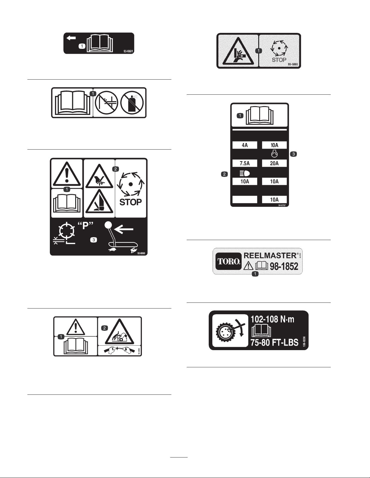
107-8841
9
Page 10
93-6691
1. Read the Operator’s Manual.
93-6692
1. Read the Operator’s Manual—do not prime or use starting
fluid.
93-6693
1. Crushing hazard of hand—wait for moving parts to stop.
94-6767
1. Read the Operator’s
Manual.
2. Headlights
3. Engine-start
1. Warning—read the
Operator’s Manual.
2. Cutting hazard of and or
foot—wait for moving
parts to stop.
(Model 03551 only)
1. Warning—read the
Operator’s Manual.
93-8060
93-8050
3. For backlapping, set the
parking brake and move
the throttle lever to Slow
(do not change the engine
speed while the reels are
running).
2. Tipping hazard—wear the
seat belt.
98-7976
1. Warning—read the Operator’s Manual.
106-9206
10
Page 11
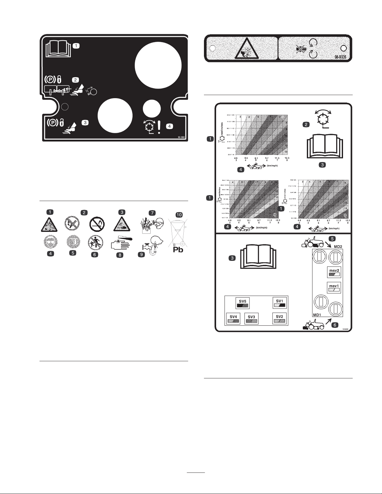
93-1263
1. Read the Operator’s Manual.
2. To lock the parking brake, secure the brake pedals with the
locking pin, press the brake pedals, and pull out the parking
brake knob.
3. To unlock the parking brake, press the brake pedal.
4. Reel failure/malfunction
98-9335
1. Cutting/dismemberment hazard, fan—stay away from moving
parts.
Battery Symbols
Some or all of these symbols are on your battery.
1. Explosion hazard
2. No fire, open flames, or
smoking.
3. Caustic liquid/chemical
burn hazard
4. Wear eye protection
5. Read the Operator’s
Manual.
6. Keep bystanders a safe
distance from the battery.
7. Wear eye protection;
explosive gases can
cause blindness and
other injuries
8. Battery acid can cause
blindness or severe
burns.
9. Flush eyes immediately
with water and get
medical help fast.
10. Contains lead; do not
discard.
1. Reel—height of cut
2. Reel—mow and backlap
3. Read the Operator’s
Manual.
104-0082
4. Machine speed
5. Rear reels circuit controls
6. Front reels circuit controls
11
Page 12

General Specifications
Kubota three cylinder, 4 cycle, liquid cooled, turbo diesel engine. 35 hp @ 3000
Engine
Main frame All welded formed steel frame, includes tie-down loops
Cooling system
rpm. Governed to 3200 rpm. 68–1/2 cubic inch (1123 cc) displacement. Heavy duty,
3-stage, remote mounted air cleaner. High water temperature shutdown switch.
Radiator capacity is approximately 240 ounces (9.4 l) of 50/50 mixture of ethylene
glycol anti–freeze. Remote mounted 32 ounces (.9 l) expansion tank. Removeable
oil cooler/radiator intake screen. Air to oil cooler, mounted to front of radiator, tips
forward for cleaning.
Fuel system
Traction system
Ground speed 0–10 mph forward, 0–4 mph reverse
Cutting unit drive system
Seat
Steering system Power steering with dedicated power source
Tires
Brakes
Electrical features
Fuel tank capacity is 10 gallons (57 l) of #2 diesel fuel. Equipped with a fuel
filter/water separator to capture water in the fuel.
Foot pedal controls forward/reverse ground speed. Hydrostatic transmission
mounted directly on a 20.9:1 ratio front axle. Axle/reservoir capacity is 160 ounces
(4.7 l). Replaceable filter mounted directly on transmission housing. Model 03551
only–Mechanical rear axle is coupled to front axle by a driveshaft and overrunning
clutch.
Reel motors feature quick disconnect for removal or installation onto cutting unit.
Hydraulic fluid reservoir capacity is 8–1/2 gallons. System protected by a filter
assembly with restriction bypass and service indicator.
Deluxe high back suspension seat with adjustable fore and aft travel, weight and
height. Tool box at left side of seat.
Two rear steering tires: 20 x 10.00-10, tubeless, 6-ply rating. Two front traction
drive tires: 26.5 x 14.00-12 tubeless, 4-ply rating. Recommended tire pressure for
front and rear tires is 10–15 psi.
Individual drum type wheel brakes on front traction wheels. Brakes controlled by
individual pedals operated by the left foot. Hydrostatic braking through traction
drive.
Automotive type electrical system. 12 volt, maintenance free battery with 530 cold
cranking Amps @ 0 degrees F. and 85 minute reserve capacity @ 85 degrees F.
40 amp alternator with I.C. regulator/rectifier. Seat switch, reel and traction interlock
switches. An electronic controller monitors and controls safety and operational
functions. Parking brake switch and individual circuit backlap switches.
Controls
Gauges
Diagnostics
Foot operated traction and brake pedals. Hand operated throttle, speed control
lever, parking brake lock, ignition switch with automatic preheat cycle, single joy
stick control for cutting unit on/off and lift lower. Cutting unit backlap controls and
reel speed controls located under seat base.
Hour meter, speedometer, fuel gauge, temperature gauge, 4 bank warning lamp: oil
pressure, water temperature, amps, and glow plug.
The Automatic Control Electronics, ACE™ system allows precise timing and control
of machine functions for maximum reliability. Optional diagnostic display connects
to an electronic control unit to pin point any electrical problems quickly and easily.
Available DATA LOG™ system allows mechanic to find intermittent problems.
12
Page 13

Measurements
Optional Equipment
Width-of-cut 100 inch (254 cm)
Overall width
Transport 88 inch (224 cm)
Outside of front tires 87 inch (221 cm)
Outside of rear tires 52–1/2 inch (133 cm)
Overall length
Without grass baskets 113 inch (287 cm)
With grass baskets 120 inch (305 cm)
Height
Without ROPS
installed
With ROPS installed 82 inch (208 cm)
Recommended
Height–of–cut
5 Blade cutting unit 1 to 1–3/4 inch (26–44 mm)
7 Blade cutting unit 1/2 to 1 inch (13–26 mm)
11 Blade cutting unit 3/8 to 3/4 inch (10–19 cm)
Weight
Model No. 03550 2962 lb. (1344 kg)*
Model No. 03551 3210 lb. 1456 kg)*
* With 7 blade cutting units and full fluid levels
59 inch (150 cm)
5 Blade Cutting Unit (7 inch) Model No. 03860
7 Blade Cutting Unit (7 inch) Model No. 03861
11 Blade Cutting Unit (7 inch) Model No. 03862
Dethatching Cutting Unit Model No. 03871
Grass Basket Kit Model No. 03882
Arm Rest Kit Model No. 30707
4 Wheel Drive Kit (For use with
model 03550 only)
T
Turf Defender
Detector
Precleaner Bowl Extension Tube
(Clamp, part number 20–4840
required to install extension tube)
Diagnostic ACE Tool Part No. 85–4750
Weight Kit Part No. 94–2836
High Torque Reel Motor Part No. 98-9998
Wiehle Roller Scraper Part No. 100-9908
Basket Tipper Kit Part No. 100-9945
Rear Roller Scraper Kit Part No. 100–9920
Full Roller Scraper Kit Part No. 99–8668
Shoulder Wiehle Roller Part No. 100-9911
Shoulder Wiehle Scraper Part No. 100-9913
Low Height–of–Cut Bedknife* Part No. 93–9774
Gauge Bar Assembly Part No. 108–6715
Angle Indicator Part No. 99-3503
Backlapping Brush Assembly Part No. 29–9100
Bedknife Screw Tool Part No. TOR510880
Cutting Unit Tool Kit Part No. TOR4070
Reel Drive Adapter Part No. TOR4074
* For height–of–cut below 1/2 inch (13mm)
Electronic Leak
Model No. 03538
Model No. 03521
Part No. 43–3810
13
Page 14

Setup
Note: Determine the left and right sides of the machine from the normal operating position.
Note: Use this chart as a checklist to ensure that all parts necessary for assembly have been received. Without these parts,
total set-up cannot be completed. Some parts may have already been assembled at the factory.
Description
Locking hood latch
Lockwasher
Nut
Key
Hood latch bracket
Hood latch strap
Capscrew, 1/4 x 3/4 inch
Flat washer, 9/32 x 5/8 inch
Locknut, 1/4 inch
Capscrew, 3/8 x 1 inch
Flange nut 1/4 inch
Flange head capscrew, 5/16 x 5/8 inch 1 Replacing the floor panel fastener for CE
Counterweight
O–ring, large
Lynch Pin
Steering Pin
Qty. Use
1
1
1
1
1
1
4
4
4
1
1
5
10
5
5
Mounting the hood latch for CE
Attaching the tipper chains to the front cutting
unit
Mounting the counterweights and motors to
cutting units
Mounting the cutting units to the traction unit
Diagnostic ACE display overlay 1 Use for diagnosing machine malfunctions
Hydraulic filter 1 Change filter after first 10 hours of operation
EEC decal
EEC certificate
Blank service decal 1 Affix to machine (International only)
Operator’s manual (traction unit) 2 Read before operating the machine.
Parts catalog 1
1
Affix to machine
2
14
Page 15
Connecting the Battery
Warning
CALIFORNIA
Proposition 65 Warning
Battery posts, terminals, and related accessories
contain lead and lead compounds, chemicals
known to the State of California to cause cancer
and reproductive harm. Wash hands after
handling.
Warning
Battery terminals or metal tools could short
against metal tractor components causing sparks.
Sparks can cause the battery gasses to explode,
resulting in personal injury.
• When removing or installing the battery, do not
allow the battery terminals to touch any metal
parts of the machine.
• Do not allow metal tools to short between the
battery terminals and metal parts of the
machine.
Warning
Incorrect battery cable routing could damage the
tractor and cables causing sparks. Sparks can
cause the battery gasses to explode, resulting in
personal injury.
• Always disconnect the negative (black) battery
cable before disconnecting the positive (red)
cable.
• Always connect the positive (red) battery cable
before connecting the negative (black) cable.
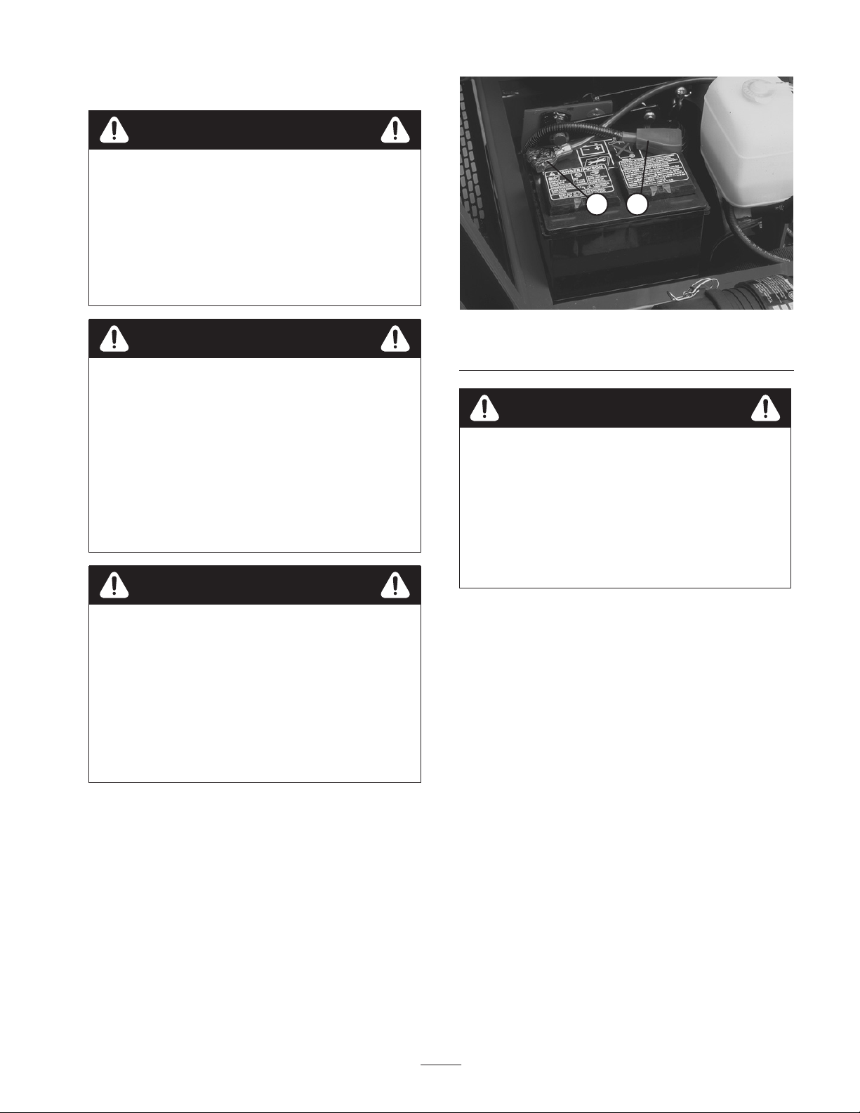
1. Open the hood.
2 1
Figure 2
1. Positive battery cable 2. Negative battery cable
Danger
Battery electrolyte contains sulfuric acid which is a
deadly poison and causes severe burns.
• Do not drink electrolyte and avoid contact with
skin, eyes or clothing. Wear safety glasses to
shield your eyes and rubber gloves to protect
your hands.
• Fill the battery where clean water is always
available for flushing the skin.
3. Slide the red, positive battery cable onto the positive
battery post and tighten nut securely (Fig. 2).
4. If removed, slide the black, negative battery cable onto
the negative battery post and tighten nut securely
(Fig. 2).
5. Coat both battery connections with Grafo 112X (skin
over) grease, Toro Part No. 505-47, petroleum jelly or
light grease to prevent corrosion and slide rubber boot
over positive terminal.
6. Close hood.
2. Ensure battery is securely fastened in place and check
battery charge with a hydrometer. If battery needs
charging, be sure at least one battery cable, preferable
the positive (+) cable, is disconnected from the battery
before connecting the charger (Fig. 2).
15
Page 16
Mounting the Hood Latch
Replacing the Floor Panel
1. Remove plug from hole in left front corner of hood
(Fig. 3).
2. Open the hood.
1
Figure 3
1. Hood plug
3. Mount locking latch to hood with lock washer and nut.
Position switch with latch toward front of machine
(Fig. 4).
4. Loosely mount latch strap to radiator support with 2
capscrews (1/4 x 3/4 inch), flat washers and locknuts
(Fig. 4).
1
Fastener
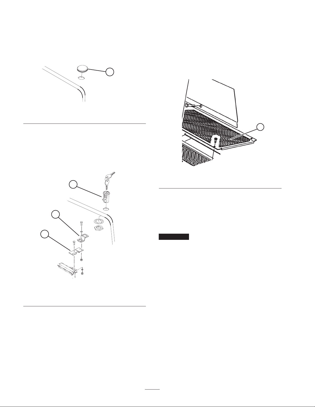
1. Remove fastener securing left front corner of floor
panel to frame (Fig. 5).
2. Replace with a flange head capscrew (5/16 x 5/8 inch)
supplied in loose parts (Fig. 5).
1. Floor panel
(Required for CE)
1
Figure 5
2
3
Figure 4
1. Locking latch
2. Latch bracket
5. Adjust latch bracket, until aligned with locking latch,
then tighten capscrews.
6. Rotate latch to locked and unlocked position with key.
Remove key and store in memorable place (Fig. 4).
7. Close the hood.
3. Latch strap
Checking the Tire Pressure
The tires are over–inflated for shipping. Therefore, release
some of the air to reduce the pressure. Correct air pressure
in the front and rear tires is 10-15 psi.
Important Maintain even pressure in all tires to assure
uniform contact with turf.
Installing the Cutting Units
Cutting unit models 03860, 03861, and 03862 can be
installed at any of the five mounting locations on the
traction unit.
Figure 6 shows the orientation of the hydraulic drive motor
for each of the five locations. For any of the locations
requiring the motor to be mounted on the right end of the
cutting unit, install a counter weight on the left end of the
cutting unit. For the locations requiring the motor to be
mounted on the left end, install a counter weight on the
right end of the cutting unit.
16
Page 17

Motor Weight
Motor Weight Weight Motor
Weight Motor Weight Motor
#1#4 #5
5
#2
#3
Figure 6
Note: Counter weight mounting capscrews are shipped
installed on the right bearing housing of the cutting units.
The capscrews on left bearing housing are to be used for
securing the hydraulic motor.
1. Remove cutting units from cartons. Assemble and
adjust per Cutting Unit Operator’s Manual.
2. Remove protective plugs from each end of cutting unit.
3. Lubricate and install a large O-ring into bearing housing
groove on each end of cutting unit (Fig. 7 & 10).
Note: Before installing cutting unit motors, lubricate
internal splines of cutting unit reel shafts with grease.
4. Install a counter weight onto appropriate end of each
cutting unit with capscrews provided (Fig. 7).
3
2
4
1
Figure 8
1. Carrier frame
2. Pivot knuckle
3. Lift arm steering plate
4. Lynch pin
5. Steering pin
7. Insert the horizontal shaft of the pivot knuckle into the
mounting tube of the carrier frame (Fig. 8).
8. Secure pivot knuckle to carrier frame with a thrust
washer, flat washer and a flange head capscrew (Fig. 8).
9. Insert a thrust washer onto vertical shaft of pivot
knuckle (Fig. 8).
3
1
2
Figure 7
1. Bearing housing
2. O–ring—large
3. Counterweight
5. Thoroughly grease the cutting unit reel bearings prior to
installation on the traction unit. Grease should be
evident at the inboard reel seals. Refer to Cutting Unit
Operator’s Manual for greasing procedure.
6. Insert a thrust washer onto horizontal shaft of pivot
knuckle as shown in Figure 8.
10. If removed, Insert the vertical shaft of the pivot knuckle
into lift arm pivot hub (Fig. 8). Guide the pivot knuckle
in place between the two rubber centering bumpers in
the under side of the lift arm steering plate.
11. Insert the lynch pin into the cross hole on the pivot
knuckle shaft (Fig. 8).
12. On front center cutting unit, remove nut securing turf
compensation spring mounting bracket to left cutting
unit stabilizer ear (Fig. 9). Insert left tipper chain onto
capscrew and secure with nut removed.
13. Secure the right tipper chain to right cutting unit
stabilizer ears with a capscrew (3/8 x 1 inch) and flange
nut supplied in loose parts (Fig. 9).
17
Page 18

3
1
2
Important Make spring adjustments with cutting unit is
mounted to traction unit and lowered to shop floor. Refer to
Traction Unit Operator’s Manual for mounting instructions.
1. Tighten lock nut on rear of spring rod until the gap C
between rear of spring bracket and front of washer is
1 inch (26 mm) (Fig. 11).
2. Tighten hex nuts on front end of spring rod until the
compressed length A of spring is 8 inches (203 mm)
(Fig. 11).
Figure 9
1. Lift chains
2. Turf compensation
mounting bracket
14. Mount the motor to the drive end of the cutting unit and
secure with two capscrews provided (Fig. 10).
Figure 10
1. Motor 2. O–ring
3. Cutting unit stabilizer ear
2
1
Note: When cutting rough or undulating turf, increase
compressed length A of the spring to 8-1/2 inch (216 mm)
and gap C between rear of spring bracket and front of
washer to 1–1/2 inches (39 mm) (Fig. 11).
Note: As compressed spring length A decreases, weight
transfer from front roller to rear roller increases and carrier
frame/cutting unit rotation angle B decreases.
Note: As gap C between spring bracket and washer
increases, cutting unit ground clearance decreases and
carrier frame/cutting unit rotation angle B increases.
B
A
C
Note: If fixed cutting unit position is required, insert
steering pin into pivot knuckle mounting hole (Fig. 8).
Hook spring wire around bottom of steering pin.
Alternate the Adjustments
Traction units are setup at the factory appropriately for
most fairway mowing applications.
The following adjustments are available for fine–tuning of
the machine to the application:
Adjusting the Turf Compensation Spring
The Turf Compensation Spring (Fig. 11), connecting carrier
frame to cutting unit, controls the amount of fore–aft
rotation available, as well as the amount of ground
clearance in transport and turn around.
The Turf Compensation Spring also transfers weight from
the front to rear roller. (This helps to reduce a wave pattern
in the turf, also known as bobbing.)
Figure 11
Lifted Height of Outer Front Cutting Units
(Enable Position)
The turnaround height of the front outer cutting units
(Number 4 & 5) may be increased to provide additional
ground clearance on contoured fairways. Contact your
distributor for assistance.
Note: The RM CONFIG time delay should not be changed
from the original setting of 0 when using this method to
adjust turn around height.
To increase the turn around height of the front cutting units
proceed as follows:
• Position machine on a level surface, lower the cutting
units and stop the engine.
18
Page 19

• Loosen the carriage bolt nut securing the lift arm switch
bracket to the #4 lift arm (left front) (Fig. 12).
Note: Additional holes are provided to further adjust, if
required.
3
Figure 12
1. Lift arm switch
2. Carriage bolt nut
• Move the lift switch bracket up in the slot to the desired
position.
• Set the distance between the lift arm switch and the flag
on the lift arm to to approximately .062 inches.
• Tighten carriage bolt nut.
1
2
3. Lift arm flag
Adjusting the Cutting Unit
Stabilizer
Rear Ballast
Model 03550 (2 Wheel Drive) complies with the CEN
standard EN 836:1997, ISO standard 5395:1990 and the
ANSI B71.4–1999 Standard when 100 lbs. (45 kg) of
calcium chloride ballast is added to rear wheels and rear
weight kit (Part No. 104–1478) is installed.
Model 03551 (4 Wheel Drive) complies with the CEN
standard EN 836:1997, ISO standard 5395:1990 and ANSI
B71.4–1999 Standard when 100 lbs. (45 kg) of calcium
chloride ballast is added to rear wheels.
Important If a puncture occurs in a tire with calcium
chloride, remove unit from turf area as quickly as possible.
To prevent possible damage to turf, immediately soak
affected area with water.
The stabilizer for the front center cutting unit can be
adjusted up or down to stabilize the cutting unit when in the
fully raised position.
1. Raise all cutting units to the transport position and shut
off the engine.
1
2
3
Figure 13
1. Cutting unit stabilizer
2. Stabilizer saddle
2. On front center cutting unit, loosen the carriage bolts
and nut securing the stabilizer saddle to stabilizer
(Fig. 13).
3. Carrier frame
3. Slide saddle down until it contacts cutting unit carrier
frame. Tighten carriage bolts and nuts.
19
Page 20

Before Operating
Note: Determine the left and right sides of the machine
from the normal operating position.
3. If oil is below full mark, remove fill cap and add oil
until level reaches full mark on dipstick (Fig. 14). Do
not over fill.
4. Install oil fill cap and close hood.
Warning
Before servicing or making adjustments to the
machine, stop the engine and remove the key from
the switch. Lower the cutting units to the ground.
Checking the Engine Oil
The engine is shipped with oil in the crankcase; however,
the oil level must be checked before and after the engine is
first started.
Crankcase capacity is approximately 128 ounces (3.8 l)
with the filter.
Use high-quality engine oil that meets the following
specifications:
API Classification Level Required: CH–4, CI–4 or
higher.
Preferred oil: SAE 15W–40 (above 0_F)
Alternate oil: SAE 10W–30 or 5W–30
(all temperatures)
Toro Premium Engine oil is available from your distributor
in either 15W–40 or 10W–30 viscosity. See the parts
catalog for part numbers.
1. Park machine on a level surface, stop engine and
remove key from ignition switch. Open the hood.
Checking the Cooling System
Clean debris off screen, oil cooler and front of radiator
daily, more often if conditions are extremely dusty and
dirty. Refer to Servicing the Engine Cooling System,
page 38.
The cooling system is filled with a 50/50 solution of water
and permanent ethylene glycol anti–freeze. Check level of
coolant in expansion tank at beginning of each day before
starting the engine. Capacity of cooling system is
307 ounces.
Caution
If the engine has been running, pressurized hot
coolant can escape and cause burns if the radiator
cap is removed.
Allow the engine to cool at least 15 minutes or until
the radiator cap is cool enough to touch without
burning hands.
5. Check level of coolant in expansion tank. Coolant level
should be between the marks on side of tank (Fig. 15).
1
2. Remove dipstick, wipe clean and reinstall dipstick.
Remove dipstick and check oil level on dipstick; Oil
level should be up to the full mark (Fig. 14).
2
1
Figure 14
1. Dip stick 2. Oil fill cap
Figure 15
1. Expansion tank
6. If coolant level is low, remove expansion tank cap and
replenish the system. Do not over fill.
7. Install expansion tank cap.
20
Page 21

Filling the Fuel Tank
Danger
Under certain conditions, diesel fuel and fuel
vapors are highly flammable and explosive. A fire
or explosion from fuel can burn you and others
and can cause property damage.
• Use a funnel and fill the fuel tank outdoors, in
an open area, when the engine is off and is cold.
Wipe up any fuel that spills.
• Do not fill the fuel tank completely full. Add fuel
to the fuel tank until the level is 1 in. (26 mm)
below the bottom of the filler neck. This empty
space in the tank allows the fuel to expand.
• Never smoke when handling fuel, and stay away
from an open flame or where fuel fumes may be
ignited by a spark.
• Store fuel in a clean, safety-approved container
and keep the cap in place.
1. Remove fuel tank cap (Fig. 16).
2. Fill tank to about 1 inch (26 mm) below top of tank, not
filler neck with No. 2 diesel fuel. Then install cap
(Fig. 16).
1
Figure 17
1. Transmission dipstick cap
3. Screw dipstick filler cap finger–tight onto filler neck
(Fig. 17). It is not necessary to tighten cap with a
wrench.
Checking the Hydraulic Fluid
The machines reservoir is filled at the factory with
approximately 8–1/2 gallons of high quality hydraulic
fluid. Check the level of the hydraulic fluid before the
engine is first started and daily thereafter. The
recommended replacement fluid is:
Toro Premium Transmission/Hydraulic Tractor
Fluid
(Available in 5 gallon pails or 55 gallon drums. See
parts catalog or Toro distributor for part numbers.)
1
Figure 16
1. Fuel tank cap
Checking the Transmission
Fluid
The front axle housing acts as the reservoir for the system.
The transmission and axle housing are shipped from the
factory with approximately 160 ounces of Mobil 424
hydraulic fluid. However, check level of transmission oil
before engine is first started and daily thereafter.
Alternate fluids: If the Toro fluid is not available, other
petroleum–based Universal Tractor Hydraulic Fluids
(UTHF) may be used provided its specifications fall within
the listed range for all the following material properties and
it meets industry standards. We do not recommend the use
of synthetic fluid. Consult with your lubricant distributor to
identify a satisfactory product Note: Toro will not assume
responsibility for damage caused by improper substitutions,
so use only products from reputable manufacturers who
will stand behind their recommendation.
Material Properties:
Viscosity, ASTM D445 cSt @ 40_C 55 to 62
cSt @ 100_C 9.1 to 9.8
Viscosity Index ASTM D2270 140 – 152
Pour Point, ASTM D97 –35_F to –46_F
Industry Specifications:
API GL–4, AGCO Powerfluid 821 XL, Ford New
Holland FNHA–2–C–201.00, Kubota UDT, John Deere
J20C, Vickers 35VQ25 and Volvo WB–101/BM.
Note: Many hydraulic fluids are almost colorless, making it
difficult to spot leaks. A red dye additive for the hydraulic
system oil is available in 2/3 oz. (20 ml) bottles. One bottle
is sufficient for 4–6 gal (15–22 1) of hydraulic oil. Order
part no. 44–2500 from your authorized Toro distributor.
21
Page 22

1. Position machine on a level surface, lower the cutting
units and stop the engine.
2. Clean area around filler neck and cap of hydraulic tank.
Remove cap from filler neck (Fig. 18).
1
2
Figure 18
1. Hydraulic tank cap
3. Remove dipstick from filler neck and wipe it with a
clean rag. Insert dipstick into filler neck; then remove it
and check level of fluid. Fluid level should be within
1/4 inch (6 mm) of mark on dipstick.
4. If level is low, add appropriate fluid to raise level to full
mark.
5. Install dipstick and cap onto filler neck.
Checking the Rear Axle
Lubricant
The rear axle has three separate reservoirs which use SAE
80W-90 wt. gear lube. Although the axle is shipped with
lubricant from the factory, check the level before operating
the machine.
1. Position the machine on a level surface.
2. Remove check plugs (3) from axle and make sure
lubricant is up to bottom of each hole
(Figures 19 and 20).
3. If level is low, remove center fill plug and add enough
lubricant to bring the level up to the bottom of the
center check plug hole (Figures 19 and 20).
(Model 03551 Only)
1
Figure 19
1. Check plug 2. Fill plug
1
Figure 20
1. Left check plug—rear part
of axle
1
Checking the Reel to Bedknife
Contact
Each day before operating, check reel to bedknife contact,
regardless if quality of cut had previously been acceptable.
There must be light contact across the full length of the reel
and bedknife (refer to Adjusting Reel to Bedknife in
Cutting Unit Operator’s Manual).
4. Remove each end check plug and add enough lubricant
to bring the level up to the bottom of each check plug
hole.
5. Install all the plugs.
Check the Torque of the Wheel
Nuts
Tighten wheel nuts to 75–80 ft-lb (102–108 NSm) after
1 to 4 hours of operation and again after 10 hours of
operation and every 250 hours thereafter.
22
Page 23

Warning
Failure to maintain proper torque of the wheel
nuts could result in personal injury.
Torque the front wheel nuts and rear wheel bolts to
75–80 ft.-lb. after 1–4 hours of operation and again
after 10 hours of operation. Torque every
250 hours thereafter.
Operation
Note: Determine the left and right sides of the machine
from the normal operating position.
Controls
Adjusting the Seat
Seat adjusting lever allows 4 inches (102 mm) fore and aft
adjustment. To adjust seat fore and aft, pull lever on left
side of seat assembly outward (Fig. 21). After moving seat
to desired location, release lever to lock seat into position.
Seat adjusting knob adjusts seat for operators weight. To
adjust for operators weight, turn spring tension knob;
clockwise to increase tension, counterclockwise to decrease
spring tension (Fig. 21).
1
Figure 22
1. Traction pedal
Brake Pedals
Two foot pedals operate individual wheel brakes for turning
assistance, parking and to aid in obtaining better sidehill
traction. Locking pin connects the pedals for parking brake
operation and transport (Fig. 23).
Parking Brake Latch
A knob on the left side of console actuates parking brake
lock. To engage parking brake, connect pedals with locking
pin, push down on both pedals and pull parking brake latch
out. To release parking brake, depress both pedals until
parking brake latch retracts (Fig. 23).
3
4
2
1
2
1
Figure 21
1. Seat adjusting lever 2. Seat adjusting knob
Traction Pedal
Controls forward and reverse operation. Depress top of
pedal to move forward and bottom to move backward
(Fig. 22). Ground speed depends on how far pedal is
depressed. For no load, maximum ground speed, fully
depress pedal while throttle is in the fast position. To stop,
reduce foot pressure on traction pedal and allow it to return
to center position.
5
6
Figure 23
1. Forward speed limiter
2. Reel control light
3. Speedometer
4. Brake pedals
7
5. Parking brake latch
6. Locking pin
7. Key switch
Traction Speed Limiter
Preset this lever to limit the amount the traction pedal can
be depressed in the forward direction to maintain a constant
mowing speed (Fig. 23).
Reel Control Light
When lit, indicates a control system problem. The light will
illuminate when the glow plugs are preheating (Fig. 23).
23
Page 24

Key Switch
Glow Plug Indicator Light
Three positions: Off, On/Preheat and Start (Fig. 23).
Speedometer
Indicates ground speed at which machine is traveling
(Fig. 23).
Lower Mow/Raise Control Lever
The lever raises and lowers the cutting units and also starts
and stops the reels (Fig. 24).
Fuel Gauge
Shows amount of fuel in tank (Fig. 24).
Engine Oil Pressure Warning Light
Indicates dangerously low engine oil pressure (Fig. 24).
2
4
1
7
8
9
5
3
6
When lit, indicates glow plugs are on (Fig. 24).
Charge Indicator
Illuminates when system charging circuit malfunctions
(Fig. 24).
Throttle Control
Move control forward to increase engine speed, rearward to
decrease speed (Fig. 24).
Enable/Disable Switch
Used in conjunction with lower mow / raise control lever
(Joystick) to operate reels. Reels can be raised but not
lowered when in mid position (Fig. 24).
Backlap Knobs
Used in conjunction with lower mow / raise control lever
for backlapping operation (Fig. 24). Refer to Backlapping
on page 49.
Reel Speed Controls
Controls RPM of front and rear cutting units (Fig. 25). #1
position is for backlapping. Remaining settings are for
mowing operations. See section in manual for operating
instructions and decal under seat for proper settings.
Figure 24
1. Lower mow/Raise control
lever
2. Fuel gauge
3. Engine coolant
temperature gauge
4. Engine oil pressure
warning light
5. Engine coolant
temperature warning light
6. Glow plug indicator light
7. Charge indicator
8. Throttle control
9. Enable/Disable switch
Engine Coolant Temperature Warning
Light
The light illuminates and engine shuts down when coolant
reaches a dangerously high temperature (Fig. 24).
2
1
1
2
Figure 25
1. Reel speed controls 2. Backlap knobs
24
Page 25

Hour Meter
(Located under control panel) shows total hours that
machine has been operated.
Warning
Before servicing or making adjustments to the
machine, stop the engine and remove the key from
the switch. Lower the cutting units to the ground.
Starting and Stopping
Important The fuel system must be bled if any of the
following situations have occurred. Refer to Bleeding the
Fuel System, page 25.
A. Initial start up of a new machine.
B. Engine has ceased running due to lack of fuel.
C. Maintenance has been performed upon fuel system
components; i.e., filter replaced, separator serviced,
etc.
1. Sit on the seat, keep foot off traction pedal. Assure
parking brake is engaged, traction pedal is in Neutral,
throttle is in Fast position and the Enable/Disable
switch is in the Disable position.
2. Turn ignition switch to On/Preheat position. An
automatic timer will control preheat for 6 seconds.
After preheat, turn key to start position. Do not crank
the engine or longer than 15 seconds. Release key
when engine starts. If additional preheat is required,
turn key to off position then to On/preheat position.
Repeat process as required.
3. Run engine at idle speed or partial throttle until engine
warms up.
Note: Move throttle to fast position when restarting a
warm engine.
4. To stop, move all controls to neutral and set parking
brake. Return throttle to the idle position, turn key to off
and remove it from the switch.
1
Figure 26
1. Fuel injection pump bleed screw
3. Turn key in ignition switch to the on position. Electric
fuel pump will begin operation, thereby forcing air out
around air bleed screw. Leave key in the on position
until solid stream of fuel flows out around screw.
Tighten screw and turn key to off.
Danger
Under certain conditions, diesel fuel and fuel
vapors are highly flammable and explosive. A fire
or explosion from fuel can burn you and others
and can cause property damage.
• Use a funnel and fill the fuel tank outdoors, in
an open area, when the engine is off and is cold.
Wipe up any fuel that spills.
• Do not fill the fuel tank completely full. Add fuel
to the fuel tank until the level is 1 inch (26 mm)
below the bottom of the filler neck. This empty
space in the tank allows the fuel to expand.
• Never smoke when handling fuel, and stay away
from an open flame or where fuel fumes may be
ignited by a spark.
• Store fuel in a clean, safety-approved container
and keep the cap in place.
Note: Normally, engine should start after above bleeding
procedures are followed. However, if engine does not start,
air may be trapped between injection pump and injectors;
refer to Bleeding Air From Injectors, page 38.
Bleeding the Fuel System
1. Raise hood over engine.
2. Open the air bleed screw on the fuel injection pump
(Fig. 26) with a 12 mm wrench.
Setting the Reel Speed
To achieve a consistent, high quality–of–cut and a uniform
after cut appearance, it is important that the reel speed
controls (located under seat) be correctly set.
Adjust the reel speed controls as follows:
1. Select the height-of-cut at which the cutting units are
set.
25
Page 26

2. Choose the desired ground speed best suited for
conditions.
3. Using the appropriate graph (See figure 27) for 5, 7 or
11 blade cutting units, determine the proper reel speed
setting.
2
1
1
2
Figure 28
1. Backlap knobs 2. Reel speed control
5. Operate the machine for several days, then examine the
cut to ensure satisfaction with the quality of cut. The reel
speed selector knobs may be set one position on either side
of the position indicated on the chart to account for
differences in grass condition, grass length removed, and
personal preference of the superintendent. For a cut with
more grass removed but slightly more clip visibility, move
the reel speed selector knobs one position lower than
specified. For a cut with less grass removed and slightly
less clip visibility, move the reel speed selector knobs one
position higher than specified.
Figure 27
4. To set reel speed, rotate knobs (Fig. 28) until indicator
arrows are in line with the number designating desired
setting.
Note: Reel speed can be increased or decreased to
compensate for turf conditions.
Adjusting the Rear Lift Arm
Counterbalance
The counterbalance spring on the rear cutting unit lift arms
can be adjusted to compensate for different turf conditions.
Decreased counterbalance will help keep the cutting units
on the ground when mowing at higher speeds and helps
maintain a uniform height-of-cut in rough conditions or in
areas of thatch build up. Each counterbalance spring may
be adjusted to one of three settings. Each increment
increases or decreases down pressure on the cutting units
by 2 lbs.
1. Position machine on a level surface, lower the cutting
units, stop the engine, engage the parking brakes and
remove key from ignition switch.
26
Page 27

Warning
Springs are under tension, use caution when
adjusting.
1
2
3
1
Figure 29
1. Counterbalance spring
2. Spring bolt
2. Remove the capscrew and locknut while relieving
spring tension (Fig. 29).
3. Move spring bolt to desired location and install
capscrew and locknut, while relieving spring tension
(Fig. 29).
3. Adjustment locations
Towing the Traction Unit
If it becomes necessary to tow the machine, tow it forward
only, for a short distance and at a speed no greater than
3 mph.
Note: If these towing limits are exceeded, severe damage to
the hydrostatic transmission will occur.
Figure 30
1. Drive shaft
Important If drive shaft is not removed before towing,
the transmission input shaft will not be able to rotate, thus
not allowing the transmission to maintain its internal
lubrication. Severe damage to the hydrostatic transmission
will occur.
2. Attach a suitable chain, strap or cable to the center of
the front frame member (Fig. 31).
1
Figure 31
1. Center of front frame member
1. Loosen and remove capscrews securing the drive shaft
to the engine drive coupler. Loosen capscrews clamping
drive shaft to transmission (Fig. 30). Remove drive
shaft.
Note: Lock both brake pedals together before towing.
3. Attach the other end of the towing device to a vehicle
that is capable of towing the machine safely and at
speeds below 3 mph.
4. An operator must be on the machine to steer it and keep
the traction pedal fully depressed in the forward
position while towing.
5. When towing is completed, reinstall driveshaft as
shown in Figure 30. The splines are designed to allow
assembly only when the two halves of the shaft are
properly oriented.
27
Page 28

Diagnostic Light
The RM 5500–D is equipped with a diagnostic light which
indicates if the electronic controller is functioning correctly.
The green diagnostic light is located under the control
panel, next to the fuse block. When the electronic controller
is functioning correctly and the key switch is moved to the
on position, the controller diagnostic light will be
illuminated. The light will blink if the controller detects a
malfunction in the electrical system. The light will stop
blinking and automatically reset when the key switch is
turned to the off position.
1
Figure 32
1. Electronic controller light
When the controller diagnostic light blinks, one of the
following problems has been detected by the controller:
A. One of the outputs has been shorted.
the machine as desired, each of the input switches, output
solenoids and relays must be connected and functioning
properly. The Diagnostic ACE display is a tool to help the
user verify correct electrical functions of the machine.
Checking the Interlock
Switches
The purpose of the interlock switches are to prevent the
engine from cranking or starting unless the traction pedal is
in neutral, the Enable/Disable switch is in disable and the
Lower Mow/Raise control is in the neutral position. In
addition, the engine will stop when the traction pedal is
depressed with operator off the seat or when parking brake
is engaged.
Caution
If safety interlock switches are disconnected or
damaged the machine could operate unexpectedly
causing personal injury.
• Do not tamper with the interlock switches.
• Check the operation of the interlock switches
daily and replace any damaged switches before
operating the machine.
• Replace switches every two years regardless of
whether they are operating properly or not.
B. One of the outputs is open circuited.
Using the diagnostic display, determine which output is
malfunctioning; refer to Checking Interlock Switches,
page 28.
If the diagnostic light is not illuminated when the key
switch is in the on position, this indicates that the electronic
controller is not operating. Possible causes are:
• Loopback is not connected.
• The light is burned out.
• Fuses are blown.
• No battery power.
Check electrical connections, input fuses and diagnostic
light bulb to determine malfunction. Make sure loopback
connector is secured to wire harness connector.
Diagnostic ACE Display
The RM 5500–D is equipped with an electronic controller
which controls most machine functions. The controller
determines what function is required for various input
switches (i.e. seat switch, key switch, etc.) and turns on the
outputs to actuate solenoids or relays for the requested
machine function. For the electronic controller to control
Verifying the Interlock Switch Function
1. Park machine on a level surface, lower the cutting units,
stop the engine and engage the parking brake.
2. Open control panel cover. Locate wire harness and
connectors near controller. Carefully unplug loop back
connector from harness connector.
1
Figure 33
1. Wire harness and connectors
28
Page 29

3. Connect the Diagnostic ACE display connector to the
harness connector. Make sure correct overlay decal is
positioned on Diagnostic ACE display.
2. Open control panel cover. Locate wire harness and
connectors near controller. Carefully unplug loopback
connector from harness connector.
4. Turn the key switch to the on position, but do not start
machine.
1
Figure 34
1. Diagnostic Ace
Note: The red text on the overlay decal refers to input
switches and the green text refers to outputs.
5. The inputs displayed LED, on lower right column of
the Diagnostic ACE, should be illuminated. If the
outputs displayed LED is illuminated, press the toggle
button, on Diagnostic ACE, to change the LED to
inputs displayed.
6. The Diagnostic ACE will illuminate the LED associated
with each of the inputs when that input switch is closed.
Individually, change each of the switches from open to
closed (i.e., sit on seat, engage traction pedal, etc.), and
note that the appropriate LED on Diagnostic ACE will
blink on and off when corresponding switch is closed.
Repeat on each switch that is it possible to be changed
by hand.
7. If switch is closed and appropriate LED does not turn
on, check all wiring and connections to switch and/or
check switches with an ohm meter. Replace any
defective switches and repair any defective wiring.
The Diagnostic ACE also has the ability to detect which
output solenoids or relays are turned on. This is a quick
way to determine if a machine malfunction is electrical or
hydraulic.
Verifying Output Function
1. Park machine on a level surface, lower the cutting units,
stop the engine and engage the parking brake.
3. Connect the Diagnostic ACE connector to the harness
connector. Make sure correct overlay decal is positioned
on Diagnostic ACE.
4. Turn the key switch to the on position, but do not start
machine.
Note: The red text on the overlay decal refers to input
switches and the green text refers to outputs.
5. The outputs displayed LED, on lower right column of
Diagnostic ACE, should be illuminated. If inputs
displayed LED is illuminated, press the toggle button,
on Diagnostic ACE, to change LED to outputs
displayed.
Note: It may be necessary to toggle between inputs
displayed and outputs displayed several times to do the
following step. To toggle back and forth, press toggle
button once. This may be done as often as required. Do not
hold the button.
6. Sit on the seat and attempt to operate the desired
function of the machine. (If you need help verifying the
correct input settings for each function, refer to the
Logic Chart on page 27) The appropriate output LED’s
should illuminate to indicate that the ECU is turning on
that function.
Note: If any output LED is blinking, this indicates an
electrical problem with that output. Repair or replace
defective electrical parts immediately. To reset a blinking
LED, turn the key switch off, then back on.
If no output LED’s are blinking, but the correct output
LED’s do not illuminate, verify that the required input
switches are in the necessary positions to allow that
function to occur. Verify correct switch function.
If the output LED’s are on as specified, but the machine
does not function properly, this indicates a non–electrical
problem. Repair as necessary.
Note: Due to electrical system constraints, the output
LED’s for start, preheat and etr/alt may not blink even
though an electrical problem may exist for those functions.
If the machine problem appears to be with one of these
functions, be certain to check the electrical circuit with a
volt/ohm meter to verify that no electrical problem exists to
these functions.
If each output switch is in the correct position and
functioning correctly, but the output LED’s are not
correctly illuminated, this indicates an ECU problem. If this
occurs, contact your Toro Distributor for assistance.
Important The Diagnostic ACE display must not be
left connected to the machine except for trouble shooting. It
is not designed to withstand the environment of the
machine’s every day use. When done using Diagnostic
29
Page 30

ACE, disconnect it from the machine and reconnect
loopback connector to harness connector. Machine will not
operate without loopback connector installed on harness.
Store the Diagnostic ACE in dry, secure location in shop,
not on machine.
Hydraulic Valve Solenoid
Functions
Use the list below to identify and describe the different
functions of the solenoids in the hydraulic manifold. Each
solenoid must be energized to allow function to occur.
Solenoid
MSV1 Front reel circuit
MSV2 Rear reel circuit
SV4 Lift front wing cutting units
SV3 Lift front center cutting unit
SV5 Lift rear cutting units
SV1 Lower any cutting units
SV1,SV2 Lift any cutting units
Function
Running the Mower
Start engine and move throttle to fast so engine is running
at maximum speed. Move the enable/disable switch to
enable and use the lower mow/raise lever to control the
cutting units (front cutting units are timed to lower before
the rear cutting units). To move forward and cut grass,
press traction pedal forward.
Transporting the mower
Move the enable/disable switch to joy stick disable and
raise the cutting units to the transport position. Be careful
when driving between objects so you do not accidentally
damage the machine or cutting units. Use extra care when
operating machine on slopes. Drive slowly and avoid sharp
turns on slopes to prevent roll overs. The cutting units
should be lowered when going downhill for steering
control.
Operating Characteristics
Becoming Familiar with the Machine
Before mowing grass, practice operating machine in an
open area. Start and stop the engine. Operate in forward
and reverse. Lower and raise cutting units and engage and
disengage reels. When you feel familiar with the machine,
practice operating up and down slopes at different speeds.
The brakes can be used to assist in turning the machine.
However, use them carefully, especially on soft or wet
grass conditions because the turf may be torn accidentally.
Individual turning brakes may also be used to help maintain
traction. For example, in some slope conditions, the uphill
wheel slips and loses traction. If this situation occurs,
depress uphill turn pedal gradually and intermittently until
the uphill wheel stops slipping, thus, increasing traction on
the downhill wheel.
Important When operating machine, always use the
seat belt and ROPS together.
Warning System
If a warning light comes on during operation, stop the
machine immediately and correct the problem before
continuing operation. Serious damage could occur if the
machine is operated with a malfunction.
30
Page 31

Maintenance
Note: Determine the left and right sides of the machine from the normal operating position.
Recommended Maintenance Schedule
Maintenance Service
Interval
After first 10 hours
After first 50 hours
After first 200 hours • Change the planetary gear oil
Every 50 hours
Every 100 hours
Every 200 hours
Every 400 hours
Maintenance Procedure
• Check the fan and alternator belt tension.
• Torque the wheel lug nuts.
• Change the transmission fluid.
• Replace the transmission filter.
• Change the engine oil and filter.
• Check the engine RPM (idle and full throttle).
• Torque the head and adjust valves.
• Change the engine oil.
• Check the air cleaner.
• Check the battery fluid level and cable connections.
• Change the engine oil filter.
• Inspect the cooling system hoses.
• Check the fan and alternator belt tension.
• Drain moisture from hydraulic tank.
• Drain moisture from fuel tank.
• Torque the wheel lug nuts.
• Check the reel bearing preload.
• Service the air cleaner.
• Replace the fuel/water separator filter.
• Replace the fuel filter.
• Inspect traction linkage movement
• Check the engine RPM (idle and full throttle).
• Torque the head and adjust valves.
1
1
• Change the hydraulic fluid
• Check rear wheel toe-in.
Every 800 hours
Every 1600 hours or
every 2 years,
whichever occurs first
1
Service air cleaner whenever indicator shows red
Important Refer to your engine operator’s manual for additional maintenance procedures.
• Pack the 2 WD rear wheel bearings.
• Change the 4 WD rear axle lubricant.
• Change the transmission fluid.
• Replace all moving hoses.
• Replace interlock safety switches.
• Flush/replace the cooling system fluid.
• Drain/flush fuel tank.
• Drain/flush hydraulic tank.
31
Page 32

Lubricating the Mower
Warning
Before servicing or making adjustments to the
machine, stop the engine and remove the key from
the switch. Lower the cutting units to the ground.
Greasing the Bearing and Bushings
The machine has grease fittings that must be lubricated
regularly with No. 2 General Purpose Lithium Base Grease.
If machine is operated under normal conditions, lubricate
all bearings and bushings after every 50 hours of operation.
Lubricate bearings and bushings immediately after every
washing, regardless of the interval listed.
The grease fitting locations and quantities are:
• Engine Drive shaft (3), (Fig. 35)
• Cutting unit carrier frame and pivot (2 ea.), (Fig. 36)
• Rear lift arm pivots (2), Drive shaft clutch (1) (Fig. 37)
• Rear axle tie rod (2), Steering cylinder ball joints (2),
Axle steering pivots (2) Rear axle pivot (1) (Fig. 38)
Figure 36
• Traction control linkage at transmission (1), Drive shaft
support bearing (1), Rear axle drive shaft (3) (Fig. 39)
• Brake pedal (1) (Fig. 40)
• Lift cylinders (5) (Fig. 41)
• Front lift arm pivots (3) (Fig. 42)
• Fan drive pulley (Fig. 43)
Figure 35
Figure 37
Figure 38
32
Page 33

Figure 39
Figure 40
Figure 42
Figure 43
Figure 41
33
Page 34

Service Interval Chart
Figure 44
34
Page 35

Daily Maintenance Checklist
Duplicate this page for routine use.
For the week of:
Maintenance Check Item
Safety Interlock Operation
Brake Operation
Engine Oil & Fuel Level
Cooling System Fluid Level
Drain Water/Fuel Separator
Air Filter Restriction Indicator
Radiator and Screen for Debris
Unusual Engine Noises
1
Unusual Operating Noises
Transmission Oil Level
Hydraulic System Oil Level
Hydraulic Filter Indicator
2
Hydraulic Hoses for Damage
Fluid Leaks
Tire Pressure
Instrument Operations
Mon. Tues. Wed. Thurs. Fri. Sat. Sun.
Reel–to–Bedknife Adjustment
Height–of–Cut Adjustment
Lubricate All Grease Fittings
3
Touch–up Damaged Paint
1
Check glow plugs and injector nozzles, if excess smoke or rough running is noted.
2
Check with engine running and oil at operating temperature.
3
Immediately after every washing, regardless of the interval listed.
Servicing the Air Cleaner
2. Service the air cleaner filters when ever air cleaner
indicator (Fig. 45) shows red or every 400 hours (more
frequently in extreme dusty or dirty conditions). Do not
Warning
over service air filter.
3. Be sure cover is sealing around air cleaner body.
Before servicing or making adjustments to the
machine, stop the engine and remove the key from
the switch. Lower the cutting units to the ground.
Servicing the Precleaner Bowl
Normally, inspect precleaner bowl daily. When conditions
1. Check air cleaner body for damage which could
possibly cause an air leak. Replace a damaged air
cleaner body.
are extremely dusty and dirty, inspect more frequently. Do
not let dust or debris build up above level marks on
precleaner bowl.
35
Page 36

1. Remove thumb screw, separate cover from precleaner
bowl.
2
3
Figure 45
1. Air cleaner indicator
2. Pre cleaner bowl
2. Empty precleaner bowl and wipe clean.
3. Assemble and install precleaner bowl, cover and thumb
screw.
Note: When operating machine in extremely dusty
conditions, an optional extension tube
(Toro Part No. 43-3810), which raises precleaner bowl
above hood, thus, lengthening the time between precleaner
bowl servicing, is available from your local authorized Toro
Distributor.
3. Dust cup
1
1
Figure 46
1. Filter element
6. Inspect new filter for shipping damage. Check sealing
end of filter. Do not install a damaged filter.
7. Insert new filter properly into air cleaner body. Make
sure filter is sealed properly by applying pressure to
outer rim of filter when installing. Do not press on
flexible center of filter.
8. Reinstall cover and secure latches.
9. Reset indicator (Fig. 45) if showing red.
Warning
Cleaning the Air Filter
1. Release latches securing air cleaner cover to air cleaner
body. Separate cover from body. Clean inside of air
cleaner cover.
2. Gently slide filter element out of air cleaner body to
reduce the amount of dust dislodged. Avoid knocking
filter against air cleaner body.
3. Inspect filter element and discard if damaged. Do not
wash or reuse a damaged filter.
4. Blow compressed air from inside to the outside of dry
filter element. Do not exceed 40 psi to prevent damage
to the element.
5. Keep air hose nozzle at least 2 inches (52 mm) from
filter and move nozzle up and down while rotating the
filter element. Inspect for holes and tears by looking
through the filter toward a bright light.
Before servicing or making adjustments to the
machine, stop the engine and remove the key from
the switch. Lower the cutting units to the ground.
Servicing the Engine Oil and
Filter
Change oil and filter initially after the first 50 hours of
operation, thereafter change the oil every 50 hours and the
filter every 100 hours.
1. Remove drain plug and let oil flow into drain pan
(Fig. 47). When oil stops, install drain plug.
36
Page 37

1. Engine oil drain plug
Servicing the Fuel Filter / Water Separator
Drain water or other contaminants from fuel filter / water
separator (Fig. 49) daily.
1. Locate fuel filter, under hood, and place a clean
container under it.
2. Loosen drain plug on bottom of filter canister. Tighten
plug after draining.
1
Figure 47
2. Remove the engine oil filter (Fig. 48). Apply a light
coat of clean oil to the new filter seal before screwing it
on. Do not over–tighten.
1
Figure 48
1. Engine oil filter
3. Add oil to crankcase; refer to Checking the Engine Oil,
page 20.
1
2
Figure 49
1. Fuel Filter/ Water
Separator
Replace filter canister after every 400 hours of operation.
1. Clean area where filter canister mounts.
2. Remove filter canister and clean mounting surface.
3. Lubricate gasket on filter canister with clean oil.
4. Install filter canister by hand until gasket contacts
mounting surface, then rotate an additional 1/2 turn.
2. Drain plug
Servicing the Fuel System
Changing the Fuel Tank
Drain and clean fuel tank every 2 years. Also, drain and
clean tank if fuel system becomes contaminated or if
machine is to be stored for an extended period. Use clean
fuel to flush out the tank.
Checking the Fuel Lines and Connections
Check lines and connections every 400 hours or yearly,
whichever comes first. Inspect for deterioration, damage, or
loose connections.
Replacing the Fuel Pre Filter
Replace the fuel pre filter after every 400 operating hours
or yearly, whichever occurs first.
1. Remove screw securing filter to frame rail.
2. Clamp both fuel lines that connect to the fuel filter so
fuel cannot drain when lines are removed.
3. Loosen the hose clamps at both ends of the filter and
pull fuel lines off filter.
4. Slide hose clamps onto ends of fuel lines. Push fuel
lines onto fuel filter and secure them with hose clamps.
Be sure arrow on side of filter points toward the
injection pump.
37
Page 38

3. Turn key in key switch to start position and watch fuel
flow around connector. Engine will crank. Turn key to
2
2
off position when solid flow is observed.
4. Tighten pipe connector securely.
5. Repeat steps on remaining nozzles.
1
Figure 50
1. Fuel filter 2. Hose clamp
Bleeding Air from the Injectors
Note: This procedure should be used only if fuel system
has been purged of air through normal priming procedures
and engine will not start; refer to Bleeding Fuel System,
page 25.
1. Loosen the pipe connection to the No. 1 nozzle and
holder assembly.
1
Servicing the Engine Cooling
System
Removing Debris
Remove debris from screen, oil coolers and radiator daily,
clean more frequently in dirty conditions.
1. Turn engine off and raise hood. Clean engine area
thoroughly of all debris.
2. Loosen clamps and pull up on screen to slide it out of
mounting tracks (Fig. 52). Clean screen thoroughly with
water or compressed air.
1
Figure 51
1. Fuel injector
2. Move throttle to fast position.
Figure 52
1. Screen
3. Slightly raise oil coolers and pivot forward (Fig. 53).
Clean both sides of oil coolers and radiator area
thoroughly with compressed air. Pivot oil coolers back
into position.
4. Install screen and close hood.
38
Page 39

2
1
1
2
3
Figure 53
1. Reel oil cooler
2. Radiator
3. Transmission oil cooler
Servicing the Engine Belts
Check condition and tension of all belts after first day of
operation and every 100 operating hours thereafter.
Servicing the Alternator Belt
1. Open hood.
2. Check tension by depressing belt midway between
alternator and crankshaft pulleys with 22 lb. (98 N) of
force. Belt should deflect 7/16 inch (11 mm) If
deflection is incorrect, proceed to step 3. If correct,
continue operation.
Figure 54
1. Alternator belt 2. Brace
3. Loosen bolt securing brace to engine and bolt securing
alternator to brace.
4. Insert pry bar between alternator and engine and pry out
on alternator.
5. When proper tension is achieved, tighten alternator and
brace bolts to secure adjustment.
Servicing the Cooling Fan Belt
1. Loosen lock nut on belt tensioner lever.
2. Apply 5–10 lb. (22–44 N) of force at end of lever to set
the proper tension on the fan belt.
3. Tighten lock nut to secure adjustment.
2
1
Figure 55
1. Cooling fan belt 2. Tensioner lever
39
Page 40

Adjusting the Throttle
1. Position throttle lever forward so it stops against seat
base slot.
2. Loosen the throttle cable connector on the lever arm at
the injection pump.
3. Hold the injection pump lever arm against the high idle
stop and tighten the cable connector.
Note: When tightened, the cable connector must be free to
swivel.
4. Torque the lock nut, used to set the friction device on
the throttle lever, to 40–55 in-lb (5–6 NSm) The
maximum force required to operate the throttle lever
should be 20 lb. (89 N).
1
Figure 57
1. Hydraulic reservoir
1
Figure 56
1. Injection pump lever arm
Warning
Before servicing or making adjustments to the
machine, stop the engine and remove the key from
the switch. Lower the cutting units to the ground.
Changing the Hydraulic Fluid
Change hydraulic fluid after every 800 operating hours, in
normal conditions. If fluid becomes contaminated, contact
your local TORO distributor because the system must be
flushed. Contaminated fluid looks milky or black when
compared to clean oil.
1. Turn engine off and set parking brake.
2. Remove drain plug from bottom of reservoir and let
hydraulic fluid flow into drain pan. Reinstall and
tighten plug when hydraulic fluid stops draining.
3. Fill reservoir with approximately 8–1/2 gallons of
hydraulic fluid. Refer to Checking Hydraulic Fluid,
page 21.
Important Use only hydraulic fluids specified. Other
fluids could cause system damage.
4. Install reservoir cap. Start engine and use all hydraulic
controls to distribute hydraulic fluid throughout the
system. Also check for leaks. Then stop the engine.
5. Check level of fluid and add enough to raise level to
full mark on dipstick. Do Not Over Fill.
Replacing the Hydraulic Filter
The hydraulic system filter head is equipped with a service
interval indicator. With the engine running, view the
indicator, it should be in the green zone. When the
indicator is in the red zone, the filter element should be
changed.
Use the Toro replacement filter (Part No. 94-2621).
Important Use of any other filter may void the
warranty on some components.
1. Position machine on a level surface, lower the cutting
units, stop the engine, engage the parking brakes and
remove key from ignition switch.
2. Clean area around filter mounting area. Place drain pan
under filter and remove filter.
40
Page 41

Using the Hydraulic System
Test Ports
1
Figure 58
1. Hydraulic filter
3. Lubricate new filter gasket and fill the filter with
hydraulic fluid.
4. Assure filter mounting area is clean. Screw filter on
until gasket contacts mounting plate. Then tighten filter
one–half turn.
5. Start engine and let run for about two minutes to purge
air from the system. Stop the engine and check for
leaks.
Checking Hydraulic Lines And
Hoses
Daily, check hydraulic lines and hoses for leaks, kinked
lines, loose mounting supports, wear, loose fittings, weather
deterioration and chemical deterioration. Make all
necessary repairs before operating.
The test ports are used to test pressure in the hydraulic
circuits. Contact your local Toro distributor for assistance.
1. Test Port #1 is used to assist in trouble shooting the
hydraulic circuit for the front cutting units and lift
cylinders.
2
1
Figure 59
1. Test port number 1 2. Test port number 2
2. Test Port #2 is used to assist in trouble shooting the
hydraulic circuit for the rear cutting units.
3. Test Port #3 is located on the rear of the hydrostatic
transmission and is used to measure the charge pressure
of the transmission.
4. Test Port #4 is located on the rear of the lift block and is
used to assist in trouble shooting the hydraulic lift
circuit.
Warning
Hydraulic fluid escaping under pressure can
penetrate skin and cause injury.
• If hydraulic fluid is injected into the skin it must
be surgically removed within a few hours by a
doctor familiar with this type of injury.
Gangrene may result if this is not done.
• Keep body and hands away from pin hole leaks
or nozzles that eject high pressure hydraulic
fluid.
• Use cardboard or paper to find hydraulic leaks.
• Safely relieve all pressure in the hydraulic
system before performing any work on the
hydraulic system.
• Make sure all hydraulic fluid hoses and lines are
in good condition and all hydraulic connections
and fittings are tight before applying pressure to
hydraulic system.
Adjusting Traction Drive For
Neutral
The machine must not creep when traction pedal is
released. If it does creep, an adjustment is required.
1. Park machine on a level surface, shut engine off and
lower cutting units to the floor. Depress only the right
brake pedal and engage the parking brake.
2. Jack up left side of machine until front tire is off the
shop floor. Support machine with jack stands to prevent
it from falling accidentally.
Note: On 4 wheel drive models, left rear tire must also be
off the shop floor or 4 wheel drive driveshaft must be
removed.
3. Under right side of machine, loosen locknut on traction
adjustment cam.
41
Page 42

4. After desired drop rate is attained, tighten setscrew to
lock adjustment.
1
1
Figure 60
1. Traction adjustment cam
Warning
Engine must be running so final adjustment of the
traction adjustment cam can be performed.
• To avoid possible personal injury, keep hands,
feet, face and other parts of the body away from
the muffler, other hot parts of the engine, and
other rotating parts.
4. Start engine and rotate cam hex in either direction until
wheel ceases rotation.
5. Tighten locknut securing adjustment.
6. Stop the engine and release the right brake. Remove
jack stands and lower the machine to the shop floor.
Test drive the machine to make sure it does not creep.
Adjusting the Cutting Unit Drop
Figure 61
1. Center cutting unit adjustment valve
Adjusting the Outside Front Cutting Units
1. Locate valve on right side of lift block (Fig. 62).
2. Loosen setscrew on valve. Rotate valve 1/2 turn
clockwise.
3. Verify drop rate adjustment by raising and lowering
cutting units several times. Readjust as required.
4. After desired drop rate is attained, tighten set screw to
lock adjustment.
1
Rate
The cutting unit lift circuit is equipped with (3) adjustable
valves used to ensure the cutting units do not drop too
quickly and damage the turf. Adjust cutting units as
follows:
Adjusting the Center Cutting Unit
1. Locate valve behind access panel above operator’s
platform (Fig. 61).
2. Loosen setscrew on valve and rotate valve
approximately 1/2 turn clockwise.
3. Verify drop rate adjustment by raising and lowering
cutting unit several times. Readjust as required.
Figure 62
1. Outside front cutting unit adjustment valve
Adjusting the Rear Cutting Units
1. Raise hood and locate valve in center of machine
behind engine (Fig. 63).
42
Page 43

Adjusting the Traction Linkage
1. Park machine on a level surface, lower cutting units to
1
the floor and shut engine off.
2. Connect brake pedals together with locking pin, push
both pedals down and pull parking brake latch out.
3. Loosen outer hex nut securing eye bolt to spring anchor
plate.
Figure 63
1. Rear cutting unit adjustment valve
2. Loosen locking ring on valve and rotate valve
approximately 1/2 turn clockwise.
3. Verify drop rate adjustment by raising and lowering
cutting units several times. Readjust as required.
4. After desired drop rate is attained, tighten locking ring
to lock adjustment.
Checking and Adjusting
Traction Linkage
Due to normal wear in the control linkage and hydrostatic
transmission, an increased amount of force may be required
to return the transmission to neutral. Periodically check the
machine.
2
3
1
5
4
Figure 64
1. Spring anchor plate
2. Eye bolt
3. Inner locknut
4. Outer locknut
5. Shorten the distance to
decrease the time
required to stop the
machine
4. Rotate, clockwise, until distance between inside of eye
bolt loop and inside of spring anchor plate is shortened
1/8 inch (3 mm), as shown in figure 64. Tighten hex
nut.
Checking the Traction Linkage
1. On a large, flat open area, drive the machine at full
throttle and full traction speed.
2. Remove foot from traction pedal and measure the
distance required for the machine to come to a stop.
3. If the distance required to stop is greater than 18 feet
(5.5 meters) an adjustment to the traction linkage is
required. Proceed to next step.
5. Operate the machine and check stopping distance.
Repeat procedure if required.
Note: Shortening the distance between inside of eye bolt
loop and inside of spring anchor plate increases the pedal
force on the traction pedal. Therefore, do not over adjust.
43
Page 44

Hydraulic Schematic
44
Page 45

Warning
Before servicing or making adjustments to the
machine, stop the engine and remove the key from
the switch. Lower the cutting units to the ground.
Adjusting the Service Brakes
Adjust the service brakes when there is more than 1 inch
(26 mm) of free travel of the brake pedal, or when the
brakes do not work effectively. Free travel is the distance
the brake pedal moves before braking resistance is felt.
1. Disengage locking pin from brake pedals so both pedals
work independently of each other.
2. To reduce free travel of brake pedals, tighten the brakes
– loosen front nut on threaded end of brake cable. Then
tighten rear nut to move cable backward until brake
pedals have 1/2 to 1 inch (13 mm to 26 mm) of free
travel. Tighten front nuts after brakes are adjusted
correctly.
2
1
Figure 66
1. Transmission suction line 2. Transmission oil filter
3. Remove line from transmission allowing fluid to drain
into drain pan.
4. Reinstall suction line to transmission.
5. Fill with oil; refer to Checking the Transmission Fluid,
page 21.
1
Figure 65
1. Brake cables
Changing the Transmission
Fluid
Change the transmission fluid after every 800 hours of
operation, in normal conditions.
1. Position machine on a level surface, lower the cutting
units, stop the engine, engage the parking brakes and
remove key from ignition switch.
2. Clean area around suction line on bottom of
transmission. Place drain pan under line.
6. Before starting the engine after changing transmission
fluid, disconnect the run (ETR) solenoid on the engine,
and crank the engine several times for 15 seconds. This
allows the charge pump to fill the transmission with
fluid before the engine is started.
Replacing the Transmission
Filter
Change the transmission filter after the first 10 hours of
operation and every 800 hours, thereafter.
Only the Toro replacement filter (Part No. 75-1330) can be
used in the hydraulic system.
Important Use of any other filter may void the
warranty on some components.
1. Position machine on a level surface, lower the cutting
units, stop the engine, engage the parking brakes and
remove key from ignition switch.
2. Clean area around filter mounting area. Place drain pan
under filter and remove filter.
3. Lubricate new filter gasket and fill the filter with
hydraulic oil.
4. Assure filter mounting area is clean. Screw filter on
until gasket contacts mounting plate. Then tighten filter
one–half turn.
45
Page 46

5. Start engine and let run for about two minutes to purge
air from the system. Stop the engine and check for
leaks. Check fluid level and replenish if necessary.
Changing Rear Axle Lubricant
(Model 03551 Only)
After every 800 hours of operation the oil in the rear axle
must be changed.
1. Position machine on a level surface.
2. Clean area around the drain plugs.
3. Remove plug allowing oil to drain into drain pans.
4. After oil is drained, apply thread locking compound
on drain plug threads and reinstall in axle.
11
Figure 67
1. Drain plug
5. Fill axle with lubricant; refer to Checking the Rear Axle
Lubricant, page 22.
1
Figure 68
1. Tie rod
2. To adjust, loosen clamps at both ends of tie rod.
3. Rotate tie rod to move front of tire inward or outward.
4. Tighten tie rod clamps when adjustment is correct.
Servicing the Battery
Warning
CALIFORNIA
Proposition 65 Warning
Battery posts, terminals, and related accessories
contain lead and lead compounds, chemicals
known to the State of California to cause cancer
and reproductive harm. Wash hands after
handling.
Checking and Adjusting the
Rear Wheel Toe–In
After every 800 operating hours or annually, check rear
wheel toe-in.
1. Measure center-to-center distance (at axle height) at
front and rear of steering tires. Front measurement must
be within ±1/8 inch (3 mm) of the rear measurement.
Important Before welding on a machine, disconnect
both cables from the battery, disconnect both wire harness
plugs from the electronic control unit and the terminal
connector from the alternator to prevent damage to the
electrical system.
Warning
Battery terminals or metal tools could short
against metal tractor components causing sparks.
Sparks can cause the battery gasses to explode,
resulting in personal injury.
• When removing or installing the battery, do not
allow the battery terminals to touch any metal
parts of the machine.
• Do not allow metal tools to short between the
battery terminals and metal parts of the
machine.
46
Page 47

Warning
Incorrect battery cable routing could damage the
tractor and cables causing sparks. Sparks can
cause the battery gasses to explode, resulting in
personal injury.
Adjusting the Parking Brake
Switch
The parking brake uses a proximity sensor located under
the cover of the steering tower. This sensor is adjusted so
the sensor locates a flag on the latch rod when the parking
brake is released.
• Always disconnect the negative (black) battery
cable before disconnecting the positive (red)
cable.
• Always connect the positive (red) battery cable
before connecting the negative (black) cable.
Note: Check battery condition weekly or after every
50 hours of operation. Keep terminals and entire battery
case clean because a dirty battery will discharge slowly. To
clean the battery, wash the entire case with solution of
baking soda and water. Rinse with clear water. Coat the
battery posts and cable connectors with Grafo 112X
(skin–over) grease (Toro Part No. 505-47) or petroleum
jelly to prevent corrosion.
Servicing the Fuses
There are 6 fuses in the machines electrical system. They
are located below control panel (Figures 69 and 70).
Using the Ace Diagnostic tool verify the brake sensor
opens and closes properly. The parking brake light on the
Diagnostic tool should be on when engaged and off when
disengaged. If the light remains on when the parking brake
is released the engine will stop when the traction system is
engaged. Should this condition exist adjust the sensor using
the Diagnostic tool to verify its operation.
The adjustment is accomplished by moving the sensor
within its slotted hole. The position of the flag on the latch
rod is over the sensor target area when the parking brake is
released. Ensure that in the engaged position the flag moves
away from the target zone of the sensor.
Installing Optional Lighting
Important If optional lighting is be added to the
traction unit, use the following schematic and part numbers
to prevent damage to the traction units electrical system.
Schematic For Optional Lighting
Black
Red
To Lights w/external ground
To Lights
87
30
Figure 69
Figure 70
Orange
23
Switch
Switch* Relay
Toro Part No. 75-1010
Honeywell Part No. 1TL1-2
Black, red and orange wires are located in control console.
Add 10 Amp fuse to fuse block at location shown
* Punch out in control panel provided for switch installation
85
86
Relay
Toro Part No. 70-1480
Bosch Part No. 0-332-204
Figure 71
Note: Make sure a good ground is achieved to prevent
damage to traction unit.
47
Page 48

Wiring Diagram
48
Page 49

Backlapping
Danger
Note: Backlapping speed may be increased by moving the
reel speed selector knob toward “13.” Each position will
increase speed approximately 100 rpm. After changing
selector, wait 30 seconds for the system to stabilize at the
new speed.
The reels may stall while backlapping and could
restart suddenly. Contact with the reels during
backlapping will cause personal injury.
• Never place hands or feet in the reel area while
the engine is running.
• Never attempt to turn the reels by hand or foot
or touch the reels while backlapping.
• Never change engine speed while backlapping.
Only backlap at idle speed.
• Stop the engine and move the desired reel speed
selector knob(s) one position closer to “13.”
Note: When backlapping, the front units all operate
together, and the rear units operate together.
1. Position the machine on a level surface, lower the
cutting units, stop the engine, engage the parking brake,
and move the Enable/Disable switch to disable position.
2. Unlock and raise the seat to expose controls.
3. Locate the reel speed selector knobs and backlap knobs
(Fig. 72). Rotate the desired backlap knob(s) to the
backlap position and the desired reel speed selector
knob(s) to position 1.
4. Make initial reel to bedknife adjustments appropriate
for backlapping on all cutting units which are to be
backlapped.
5. Start engine and run at idle speed.
Caution
Contact with the reels or other moving parts can
result in personal injury.
• Keep finger, hands, and clothing away from the
reels and other moving parts.
• Never use a short handles brush to apply
lapping compound.
6. Select either front, rear, or both backlap knobs to
determine which reels will be backlapped.
7. Move Enable/Disable switch to enable position. Move
Lower Mow/Lift control forward to start backlapping
operation on designated reels.
8. Apply lapping compound with a long handle brush
(Toro Part No. 29-9100). Never use a short handled
brush (Fig. 73).
2
1
1. Reel speed selector
knobs
Figure 72
2. Backlap knobs
1
1
2
Figure 73
1. Long handle brush
9. If reels stall or become erratic while backlapping, stop
backlapping by moving the Lower Mow/Lift control
lever rearward. Once the reels have stopped, move the
desired reel speed selector knob(s) one position closer
to 13. Resume backlapping by moving the Lower
Mow/Lift control lever forward.
49
Page 50

10. To make an adjustment to the cutting units while
backlapping, turn reels off by moving the Lower
Mow/Raise lever rearward; move the Enable/Disable
switch to disable and turn the engine off. After
adjustments have been completed, repeat steps 5–9.
11. Backlap until the reels can cut paper.
Maintaining the Cutting Unit
1. When the cutting unit is adequately sharpened, a burr
will form on the front edge of the knife. Using a file,
carefully remove the burr without dulling the cutting
edge (Fig. 74).
2. Repeat procedure for all cutting units to be backlapped.
When backlap operation has been completed, return the
backlap knobs to the forward flow position, lower seat and
wash all lapping compound off cutting units. Adjust cutting
unit reel to bedknife as needed.
Note: If the backlap knobs are not returned to the forward
flow position after backlapping, the cutting units will not
raise or function properly.
Figure 74
50
Page 51

Storage
Traction Unit
Engine
1. Drain the engine oil from the oil pan and replace the
drain plug.
1. Thoroughly clean the traction unit, cutting units and the
engine.
2. Check the tire pressure. Inflate all traction unit tires to
10–15 psi.
3. Check all fasteners for looseness; tighten as necessary.
4. Grease or oil all grease fittings and pivot points. Wipe
up any excess lubricant.
5. Lightly sand and use touch–up paint on painted areas
that are scratched, chipped, or rusted. Repair any dents
in the metal body.
6. Service the battery and cables as follows:
A. Remove the battery terminals from the battery posts.
B. Clean the battery, terminals, and posts with a wire
brush and baking soda solution.
C. Coat the cable terminals and battery posts with
Grafo 112X skin–over grease
(Toro Part No. 505-47) or petroleum jelly to prevent
corrosion.
D. Slowly recharge the battery every 60 days for
24 hours to prevent lead sulfation of the battery.
2. Remove and discard the oil filter. Install a new oil filter.
3. Refill oil pan with 128 ounces of SAE 15W-40 motor
oil.
4. Start the engine and run at idle speed for approximately
two minutes.
5. Stop the engine.
6. Thoroughly drain all fuel from the fuel tank, lines and
the fuel filter/water separator assembly.
7. Flush the fuel tank with fresh, clean diesel fuel.
8. Re–secure all fuel system fittings.
9. Thoroughly clean and service the air cleaner assembly.
10. Seal the air cleaner inlet and the exhaust outlet with
weatherproof tape.
11. Check anti–freeze protection and add as needed for
expected minimum temperature in your area.
Warning
Charging the battery produces gasses that can
explode.
Never smoke near the battery and keep sparks and
flames away from battery.
51
Page 52

The Toro General Commercial Products Warranty
A Two-Year Limited Warranty
Conditions and Products Covered
The Toro Company and its affiliate, Toro Warranty Company,
pursuant to an agreement between them, jointly warrant your Toro
Commercial Product (“Product”) to be free from defects in
materials or workmanship for two years or 1500 operational
hours*, whichever occurs first. Where a warrantable condition
exists, we will repair the Product at no cost to you including
diagnosis, labor, parts, and transportation. This warranty begins
on the date the Product is delivered to the original retail purchaser.
* Product equipped with hour meter
Instructions for Obtaining Warranty Service
You are responsible for notifying the Commercial Products
Distributor or Authorized Commercial Products Dealer from whom
you purchased the Product as soon as you believe a warrantable
condition exists.
If you need help locating a Commercial Products Distributor or
Authorized Dealer, or if you have questions regarding your
warranty rights or responsibilities, you may contact us at:
Toro Commercial Products Service Department
Toro Warranty Company
8111 Lyndale Avenue South
Bloomington, MN 55420-1196
952-888-8801 or 800-982-2740
E-mail: commercial.service@toro.com
Owner Responsibilities
As the Product owner, you are responsible for required maintenance and adjustments stated in your operator’s manual. Failure
to perform required maintenance and adjustments can be grounds
for disallowing a warranty claim.
Items and Conditions Not Covered
Not all product failures or malfunctions that occur during the
warranty period are defects in materials or workmanship. This
express warranty does not cover the following:
• Product failures which result from the use of non-Toro
replacement parts, or from installation and use of add-on,
modified, or unapproved accessories
• Product failures which result from failure to perform required
maintenance and/or adjustments
• Product failures which result from operating the Product in an
abusive, negligent or reckless manner
• Parts subject to consumption through use unless found to be
defective. Examples of parts which are consumed, or used up,
during normal Product operation include, but are not limited to,
blades, reels, bedknives, tines, spark plugs, castor wheels,
tires, filters, belts, and certain sprayer components such as
diaphragms, nozzles, and check valves, etc.
• Failures caused by outside influence. Items considered to be
outside influence include, but are not limited to, weather,
storage practices, contamination, use of unapproved coolants,
lubricants, additives, or chemicals, etc.
• Normal “wear and tear” items. Normal “wear and tear” includes,
but is not limited to, damage to seats due to wear or abrasion,
worn painted surfaces, scratched decals or windows, etc.
Parts
Parts scheduled for replacement as required maintenance are
warranted for the period of time up to the scheduled replacement
time for that part.
Parts replaced under this warranty become the property of Toro.
Toro will make the final decision whether to repair any existing part
or assembly or replace it. Toro may use factory remanufactured
parts rather than new parts for some warranty repairs.
General Conditions
Repair by an Authorized Toro Distributor or Dealer is your sole
remedy under this warranty.
Neither The Toro Company nor Toro Warranty Company is
liable for indirect, incidental or consequential damages in
connection with the use of the Toro Products covered by this
warranty, including any cost or expense of providing substitute equipment or service during reasonable periods of
malfunction or non-use pending completion of repairs under
this warranty. Except for the Emissions warranty referenced
below, if applicable, there is no other express warranty. All
implied warranties of merchantability and fitness for use are
limited to the duration of this express warranty.
Some states do not allow exclusions of incidental or consequential
damages, or limitations on how long an implied warranty lasts, so
the above exclusions and limitations may not apply to you.
This warranty gives you specific legal rights, and you may also
have other rights which vary from state to state.
Note regarding engine warranty: The Emissions Control System
on your Product may be covered by a separate warranty meeting
requirements established by the U.S. Environmental Protection
Agency (EPA) and/or the California Air Resources Board (CARB).
The hour limitations set forth above do not apply to the Emissions
Control System Warranty. Refer to the Engine Emission Control
Warranty Statement printed in your operator’s manual or contained in the engine manufacturer’s documentation for details.
Countries Other than the United States or Canada
Customers who have purchased Toro products exported from the United States or Canada should contact their Toro Distributor (Dealer)
to obtain guarantee policies for your country, province, or state. If for any reason you are dissatisfied with your Distributor’s service or
have difficulty obtaining guarantee information, contact the Toro importer. If all other remedies fail, you may contact us at Toro Warranty
Company.
Part No. 374-0031 Rev. C
 Loading...