

Page 1

FormNo.3363-235RevB
Reelmaster
ModelNo.03431—SerialNo.310000001andUp
®
2000TractionUnit
ToregisteryourproductordownloadanOperator'sManualorPartsCatalogatnocharge,gotowww.T oro.com.OriginalInstructions(EN)
Page 2

Warning
CALIFORNIA
Proposition65Warning
Dieselengineexhaustandsomeofits
constituentsareknowntotheStateof
Californiatocausecancer,birthdefects,
andotherreproductiveharm.
injuryordeathifyoudonotfollowtherecommended
precautions.
Figure1
1.Safetyalertsymbol
ThissparkignitionsystemcomplieswithCanadian
ICES-002.
Important:Thisengineisnotequippedwitha
sparkarrestermufer.ItisaviolationofCalifornia
PublicResourceCodeSection4442touseoroperate
theengineonanyforest-covered,brush-covered,or
grass-coveredland.Otherstatesorfederalareas
mayhavesimilarlaws.
Introduction
Thismachineisaride-on,reel-bladelawnmower
intendedtobeusedbyprofessional,hiredoperatorsin
commercialapplications.Itisprimarilydesignedfor
cuttinggrassonwell-maintainedlawnsinparks,golf
courses,sportselds,andoncommercialgrounds.Itis
notdesignedforcuttingbrush,mowinggrassandother
growthalongsidehighways,orforagriculturaluses.
Readthisinformationcarefullytolearnhowtooperate
andmaintainyourproductproperlyandtoavoidinjury
andproductdamage.Youareresponsibleforoperating
theproductproperlyandsafely.
Thismanualuses2otherwordstohighlightinformation.
Importantcallsattentiontospecialmechanical
informationandNoteemphasizesgeneralinformation
worthyofspecialattention.
YoumaycontactTorodirectlyatwww .Toro.comfor
productandaccessoryinformation,helpndinga
dealer,ortoregisteryourproduct.
Wheneveryouneedservice,genuineToroparts,or
additionalinformation,contactanAuthorizedService
DealerorToroCustomerServiceandhavethemodel
andserialnumbersofyourproductready.Themodel
andserialnumbersarestampedintoaplatethatis
rivetedtotheframeofthemachine.Writethenumbers
inthespaceprovided.
ModelNo.
SerialNo.
Thismanualidentiespotentialhazardsandhas
safetymessagesidentiedbythesafetyalertsymbol
(Figure1),whichsignalsahazardthatmaycauseserious
©2010—TheT oro®Company
8111LyndaleAvenueSouth
Bloomington,MN55420
Contactusatwww.Toro.com.
2
PrintedintheUSA.
AllRightsReserved
Page 3

Contents
Introduction.................................................................2
Safety...........................................................................4
SafeOperatingPractices.......................................4
ToroRidingMowerSafety....................................6
SoundPowerLevel...............................................7
SoundPressureLevel...........................................7
VibrationLevel....................................................7
SafetyandInstructionalDecals.............................7
Setup..........................................................................12
1InstallingtheRearWheel.................................13
2AdjustingtheRearCarrierFrame
Height............................................................13
3MountingtheCarrierFramestotheCutting
Units..............................................................14
4InstallingtheFrontLiftArms...........................14
5MountingtheCuttingUnitDrive
Motors...........................................................15
6MountingtheCuttingUnits.............................16
7InstallingtheCounterbalanceSprings...............16
8AddingRearBallast..........................................19
9ActivatingandChargingtheBattery..................20
10InstallingCECompliantDecals......................20
11Breaking-inaNewMachine............................21
ProductOverview......................................................21
Controls.............................................................21
Specications.....................................................23
Attachments/Accessories...................................23
Operation...................................................................24
CheckingtheEngineOilLevel............................24
AddingFuel.......................................................25
CheckingtheCoolingSystem..............................26
CheckingtheHydraulicFluid..............................27
CheckingtheTirePressure.................................28
CheckingtheReeltoBedknifeContact................28
ChecktheTorqueoftheWheelNuts...................28
BleedingtheFuelSystem....................................28
StartingandStoppingtheEngine........................29
CheckingtheOperationoftheInterlock
Switches.........................................................30
TowingtheTractionUnit....................................30
OperatingCharacteristics...................................30
SettingtheReelSpeed.........................................31
TrainingPeriod...................................................32
BeforeMowing..................................................32
TransportOperation..........................................32
InspectionandClean-UpAfterMowing..............32
StandardControlModule(SCM)........................32
Maintenance...............................................................35
RecommendedMaintenanceSchedule(s)................35
DailyMaintenanceChecklist...............................36
ServiceIntervalChart.........................................37
PremaintenanceProcedures....................................37
RemovingtheHood...........................................38
Lubrication.............................................................38
GreasingtheBearingsandBushings....................38
EngineMaintenance...............................................40
ServicingtheAirCleaner....................................40
ChangingtheEngineOilandFilter.....................40
FuelSystemMaintenance.......................................41
CheckingtheFuelLinesandConnections...........41
DrainingW aterfromtheWaterSeparator............41
ReplacingtheFuelFilterCanister........................42
BleedingAirfromtheFuelInjectors...................42
ElectricalSystemMaintenance................................43
ServicingtheBattery...........................................43
Fuses..................................................................43
DriveSystemMaintenance.....................................44
AdjustingtheTractionDriveforNeutral.............44
AdjustingtheNeutralSwitch..............................45
CoolingSystemMaintenance..................................45
RemovingDebrisfromtheCooling
System............................................................45
BrakeMaintenance.................................................46
AdjustingtheParkingBrake................................46
BeltMaintenance....................................................47
TensioningtheAlternatorBelt............................47
TensioningtheHydraulicPumpBelt...................47
ControlsSystemMaintenance.................................48
AdjustingtheTractionPedal...............................48
AdjustingtheTractionPedalDamper..................48
HydraulicSystemMaintenance...............................49
ChangingtheHydraulicFluid.............................49
HydraulicSystemTestPorts...............................50
CuttingUnitSystemMaintenance...........................50
BacklappingtheCuttingUnits............................50
Storage.......................................................................51
PreparingtheTractionUnit................................51
StoringtheBattery..............................................51
PreparingtheEngine..........................................51
Schematics.................................................................53
3
Page 4

Safety
ThismachinemeetsorexceedsCENstandard
EN836:1997,ISOstandard5395:1990,andANSI
B71.4-2004specicationsineffectattimeof
production,whenequippedwithrearweight.Refer
tothesectioninthismanualonInstallingRear
Weight.
Improperuseormaintenancebytheoperator
orownercanresultininjury.Toreducethe
potentialforinjury,complywiththesesafety
instructionsandalwayspayattentiontothesafety
alertsymbol,whichmeansCaution,Warning,or
Danger—personalsafetyinstruction.Failureto
complywiththeinstructionmayresultinpersonal
injuryordeath.
SafeOperatingPractices
ThefollowinginstructionsarefromtheCENstandard
EN836:1997,ISOstandard5395:1990,andANSI
B71.4-2004.
Training
•Readtheoperator’smanualandothertraining
materialcarefully .Befamiliarwiththecontrols,
safetysigns,andtheproperuseoftheequipment.
•Neverallowchildrenorpeopleunfamiliarwiththese
instructionstouseorservicethemower.Local
regulationsmayrestricttheageoftheoperator.
•Nevermowwhilepeople,especiallychildren,orpets
arenearby .
•Keepinmindthattheoperatororuserisresponsible
foraccidentsorhazardsoccurringtootherpeopleor
theirproperty.
•Donotcarrypassengers.
•Alldriversandmechanicsshouldseekandobtain
professionalandpracticalinstruction.Theowneris
responsiblefortrainingtheusers.Suchinstruction
shouldemphasizethefollowing:
–Theneedforcareandconcentrationwhen
workingwithride-onmachines
–Controlofaride-onmachineslidingonaslope
willnotberegainedbytheapplicationofthe
brake.Themainreasonsforlossofcontrolare
asfollows:
◊Insufcientwheelgrip
◊Beingdriventoofast
◊Inadequatebraking
◊Thetypeofmachineisunsuitableforitstask
◊Lackofawarenessoftheeffectofground
conditions,especiallyslopes
◊Incorrecthitchingandloaddistribution
•Theowner/usercanpreventandisresponsiblefor
accidentsorinjuriesoccurringtohimselforherself,
otherpeople,orproperty.
Preparation
•Whilemowing,alwayswearsubstantialfootwear,
longtrousers,hardhat,safetyglasses,andear
protection.Longhair,looseclothing,orjewelrymay
gettangledinmovingparts.Donotoperatethe
equipmentwhenbarefootorwearingopensandals.
•Thoroughlyinspecttheareawheretheequipment
istobeusedandremoveallobjectswhichmaybe
thrownbythemachine.
•Warning—Fuelishighlyammable.Takethe
followingprecautions:
–Storefuelincontainersspecicallydesignedfor
thispurpose.
–Refueloutdoorsonlyanddonotsmokewhile
refuelling.
–Addfuelbeforestartingtheengine.Never
removethecapofthefueltankoraddfuelwhile
theengineisrunningorwhentheengineishot.
–Iffuelisspilled,donotattempttostartthe
enginebutmovethemachineawayfromthe
areaofspillageandavoidcreatinganysourceof
ignitionuntilfuelvaporshavedissipated.
–Replaceallfueltanksandcontainercapssecurely .
•Replacefaultysilencers/mufers.
•Evaluatetheterraintodeterminewhataccessories
andattachmentsareneededtoproperlyand
safelyperformthejob.Onlyuseaccessoriesand
attachmentsapprovedbythemanufacturer.
•Checkthattheoperator’spresencecontrols,safety
switches,andshieldsareattachedandfunctioning
properly.Donotoperateunlesstheyarefunctioning
properly.
Operation
•Donotoperatetheengineinaconnedspacewhere
dangerouscarbonmonoxidefumescancollect.
•Mowonlyindaylightoringoodarticiallight.
•Beforeattemptingtostarttheengine,disengageall
bladeattachmentclutches,shiftintoneutral,and
engagetheparkingbrake.
•Rememberthereisnosuchthingasasafeslope.
Travelongrassslopesrequiresparticularcare.To
guardagainstoverturning:
4
Page 5

–Donotstoporstartsuddenlywhengoingupor
downhill.
–Machinespeedsshouldbekeptlowonslopes
andduringtightturns.
–Stayalertforhumpsandhollowsandother
hiddenhazards.
–Donotturnsharply.Usecarewhenreversing.
–Usecounterweight(s)orwheelweightswhen
suggestedintheoperator’smanual.
•Stayalertforholesintheterrainandotherhidden
hazards.
•Watchoutfortrafcwhencrossingornearroadways.
•Stopthebladesrotatingbeforecrossingsurfaces
otherthangrass.
•Whenusinganyattachments,neverdirectdischarge
ofmaterialtowardbystandersnorallowanyonenear
themachinewhileinoperation.
•Neveroperatethemachinewithdamagedguards,
shields,orwithoutsafetyprotectivedevicesinplace.
Besureallinterlocksareattached,adjustedproperly,
andfunctioningproperly.
•Donotchangetheenginegovernorsettingsor
over-speedtheengine.Operatingtheengineat
excessivespeedmayincreasethehazardofpersonal
injury.
•Beforeleavingtheoperator’ sposition:
–Stoponlevelground.
–Disengagethepowertake-offandlowerthe
attachments.
–Changeintoneutralandsettheparkingbrake.
–Stoptheengineandremovethekey.
•Disengagedrivetoattachmentswhentransporting
ornotinuse.
•Stoptheengineanddisengagethedrivetothe
attachment:
–Beforerefuelling
–Beforeremovingthegrasscatcher/catchers
–Beforemakingheightadjustmentunless
adjustmentcanbemadefromtheoperator’s
position
–Beforeclearingblockages
–Beforechecking,cleaningorworkingonthe
mower
–Afterstrikingaforeignobjectorifanabnormal
vibrationoccurs.Inspectthemowerfordamage
andmakerepairsbeforerestartingandoperating
theequipment.
•Reducethethrottlesettingduringenginerun-out.If
theengineisprovidedwithafuelshut-offvalve,turn
thefueloffattheconclusionofmowing.
•Keephandsandfeetawayfromthecuttingunits.
•Lookbehindanddownbeforebackinguptobesure
ofaclearpath.
•Slowdownandusecautionwhenmakingturnsand
crossingroadsandsidewalks.Stopcylinders/reels
ifnotmowing.
•Donotoperatethemowerundertheinuenceof
alcoholordrugs.
•Lightningcancausesevereinjuryordeath.If
lightningisseenorthunderisheardinthearea,do
notoperatethemachine;seekshelter.
•Usecarewhenloadingorunloadingthemachine
intoatrailerortruck.
•Usecarewhenapproachingblindcorners,shrubs,
trees,orotherobjectsthatmayobscurevision.
MaintenanceandStorage
•Keepallnuts,boltsandscrewstighttobesurethe
equipmentisinsafeworkingcondition.
•Neverstoretheequipmentwithfuelinthetank
insideabuildingwherefumesmayreachanopen
ameorspark.
•Allowtheenginetocoolbeforestoringinany
enclosure.
•Toreducetherehazard,keeptheengine,
silencer/mufer,batterycompartment,andfuel
storageareafreeofgrass,leaves,orexcessivegrease.
•Checkthegrasscatcherfrequentlyforwearor
deterioration.
•Keepallpartsingoodworkingconditionandall
hardwareandhydraulicttingstightened.Replaceall
wornordamagedpartsanddecals.
•Ifthefueltankhastobedrained,dothisoutdoors.
•Becarefulduringadjustmentofthemachineto
prevententrapmentofthengersbetweenmoving
bladesandxedpartsofthemachine.
•Onmulti-cylinder/multi-reelmachines,takecare
asrotatingonecylinder/reelcancauseother
cylinders/reelstorotate.
•Disengagedrives,lowerthecuttingunits,setparking
brake,stopengine,andremovekeyfromignition.
Waitforallmovementtostopbeforeadjusting,
cleaning,orrepairing.
•Cleangrassanddebrisfromcuttingunits,drives,
silencers/mufers,andenginetohelppreventres.
Cleanupoilorfuelspillage.
5
Page 6

•Usejackstandstosupportcomponentswhen
required.
•Usingthemachinedemandsattention.T oprevent
lossofcontrol:
•Carefullyreleasepressurefromcomponentswith
storedenergy.
•Disconnectbatterybeforemakinganyrepairs.
Disconnectthenegativeterminalrstandthe
positivelast.Reconnectpositiverstandnegative
last.
•Usecarewhencheckingthecylinders/reels.Wear
glovesandusecautionwhenservicingthem.
•Keephandsandfeetawayfrommovingparts.If
possible,donotmakeadjustmentswiththeengine
running.
•Chargebatteriesinanopenwellventilatedarea,
awayfromsparkandames.Unplugchargerbefore
connectingordisconnectingfrombattery.Wear
protectiveclothinganduseinsulatedtools.
ToroRidingMowerSafety
Thefollowinglistcontainssafetyinformationspecic
toToroproductsorothersafetyinformationthatyou
mustknowthatisnotincludedintheCEN,ISO ,or
ANSIstandards.
Thisproductiscapableofamputatinghandsand
feetandthrowingobjects.Alwaysfollowallsafety
instructionstoavoidseriousinjuryordeath.
–Donotdriveclosetosandtraps,ditches,creeks,
orotherhazards.
–Reducespeedwhenmakingsharpturns.Avoid
suddenstopsandstarts.
–Whennearorcrossingroads,alwaysyieldthe
right-of-way.
–Applytheservicebrakeswhengoingdownhillto
keepforwardspeedslowandtomaintaincontrol
ofthemachine.
•Raisethecuttingunitswhendrivingfromonework
areatoanother.
•Donottouchtheengine,silencer/mufer,or
exhaustpipewhiletheengineisrunningorsoon
afterithasstoppedbecausetheseareascouldbehot
enoughtocauseburns.
•Iftheenginestallsorlosesheadwayandcannotmake
ittothetopofaslope,donotturnthemachine
around.Alwaysbackslowly ,straightdowntheslope.
•Whenapersonorpetappearsunexpectedlyin
ornearthemowingarea,stopmowing.Careless
operation,combinedwithterrainangles,ricochets,
orimproperlypositionedguardscanleadtothrown
objectinjuries.Donotresumemowinguntilthe
areaiscleared.
Useofthisproductforpurposesotherthanitsintended
usecouldprovedangeroustouserandbystanders.
Engineexhaustcontainscarbonmonoxide,
whichisanodorless,deadlypoisonthatcan
killyou.
Donotrunengineindoorsorinanenclosed
area.
•Knowhowtostoptheenginequickly.
•Donotoperatethemachinewhilewearingtennis
shoesorsneakers.
•Wearingsafetyshoesandlongpantsisadvisableand
requiredbysomelocalordinancesandinsurance
regulations.
•Handlefuelcarefully.Wipeupanyspills.
•Checkthesafetyinterlockswitchesdailyforproper
operation.Ifaswitchshouldfail,replacetheswitch
beforeoperatingthemachine.
•Beforestartingtheengine,sitontheseat.
MaintenanceandStorage
•Makesureallhydrauliclineconnectorsaretightand
allhydraulichosesandlinesareingoodcondition
beforeapplyingpressuretothesystem.
•Keepyourbodyandhandsawayfrompinhole
leaksornozzlesthatejecthydraulicuidunder
highpressure.Usepaperorcardboard,notyour
hands,tosearchforleaks.Hydraulicuidescaping
underpressurecanhavesufcientforcetopenetrate
theskinandcauseseriousinjury.Seekimmediate
medicalattentionifuidisinjectedintoskin.
•Beforedisconnectingorperforminganyworkon
thehydraulicsystem,allpressureinthesystemmust
berelievedbystoppingtheengineandloweringthe
cuttingunitsandattachmentstotheground.
•Checkallfuellinesfortightnessandwearona
regularbasis.Tightenorrepairthemasneeded.
•Iftheenginemustberunningtoperforma
maintenanceadjustment,keephands,feet,clothing,
andanypartsofthebodyawayfromthecutting
units,attachments,andanymovingparts.Keep
everyoneaway.
6
Page 7
•Toensuresafetyandaccuracy,haveanAuthorized
ToroDistributorcheckthemaximumenginespeed
withatachometer.Maximumgovernedenginespeed
shouldbe3200RPM.
•Ifmajorrepairsareeverneededorifassistanceis
desired,contactanAuthorizedToroDistributor.
•UseonlyToro-approvedattachmentsand
replacementparts.Thewarrantymaybevoidedif
usedwithunapprovedattachments.
Soundpressurelevelwasdeterminedaccordingtothe
proceduresoutlinedinEN836.
VibrationLevel
Hand-Arm
Measuredvibrationlevelforrighthand=1.54m/s
Measuredvibrationlevelforlefthand=1.04m/s
2
2
SoundPowerLevel
Thisunithasaguaranteedsoundpowerlevelof100
dBA,whichincludesanUncertaintyValue(K)of1dBA.
Soundpowerlevelwasdeterminedaccordingtothe
proceduresoutlinedinEN11094.
SoundPressureLevel
Thisunithasasoundpressurelevelattheoperator’s
earof87dBA,whichincludesanUncertaintyValue(K)
of1dBA.
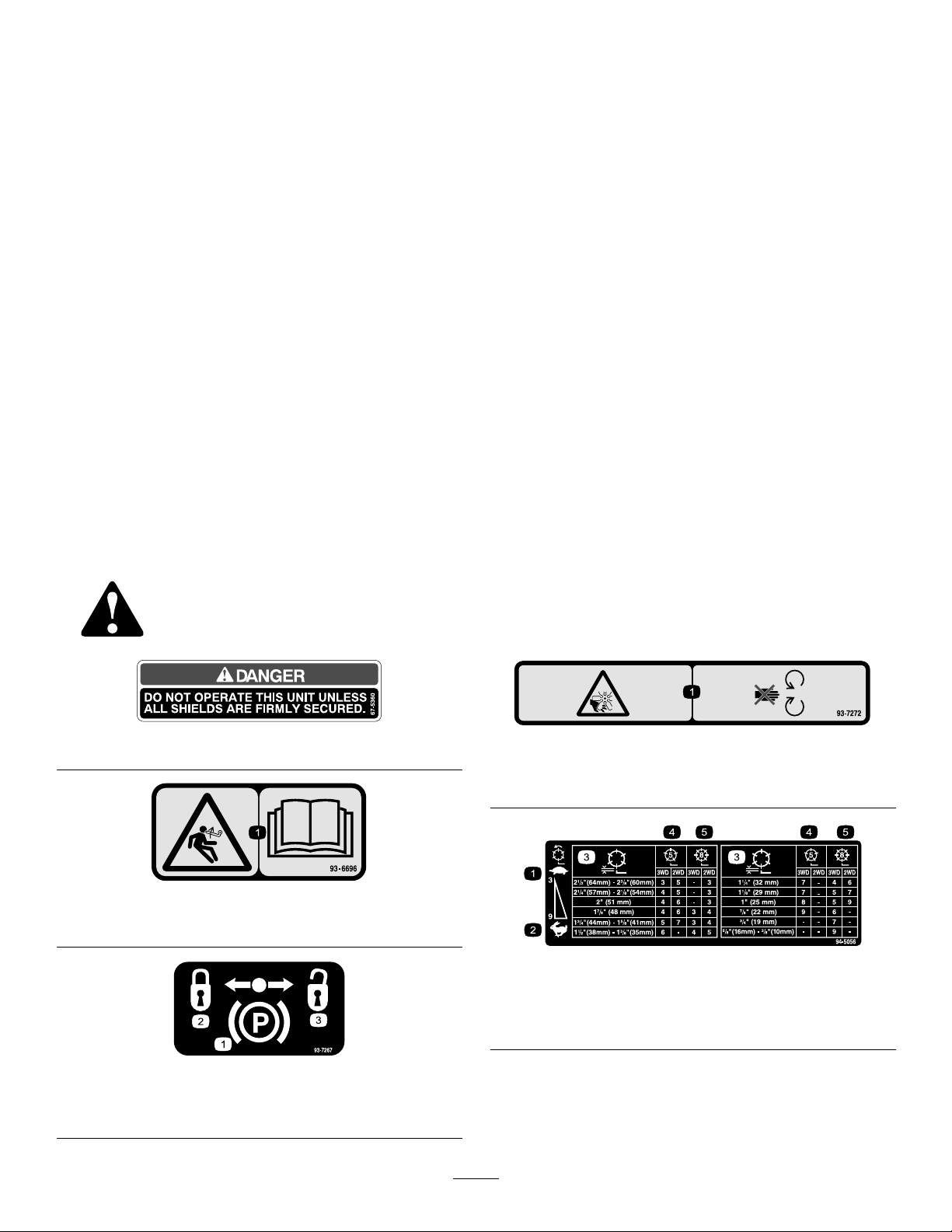
SafetyandInstructionalDecals
Safetydecalsandinstructionsareeasilyvisibletotheoperatorandarelocatednearanyareaof
potentialdanger.Replaceanydecalthatisdamagedorlost.
UncertaintyValue(K)=0.5m/s
2
Measuredvaluesweredeterminedaccordingtothe
proceduresoutlinedinEN836.
WholeBody
Measuredvibrationlevel=6.22m/s
UncertaintyValue(K)=0.4m/s
2
2
Measuredvaluesweredeterminedaccordingtothe
proceduresoutlinedinEN836.
67-5360
93-6696
1.Storedenergyhazard—readtheOperator’sManual.
93-7267
1.Parkingbrake3.Unlocked
2.Locked
93-7272
1.Cutting/dismembermenthazard;fan—stayawayfrom
movingparts.
94-5056
1.Reelspeed—slow4.5Bladecuttingunit
2.Reelspeed—fast
3.Reelheight
5.8Bladecuttingunit
7
Page 8
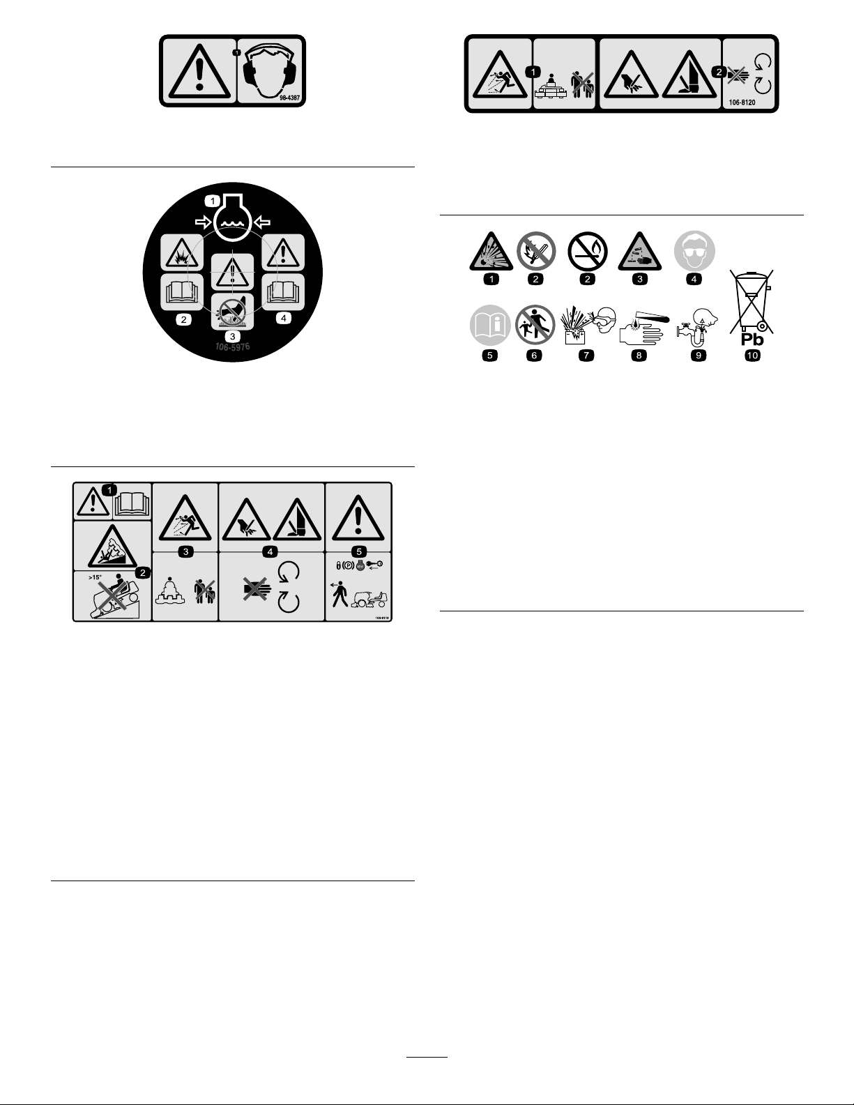
1.Warning—wearhearingprotection.
98-4387
106-8120
1.Thrownobjecthazard—keepbystandersasafedistance
fromthemachine.
2.Cuttinghazardofhandandfoot—stayawayfrommoving
parts.
106-5976
1.Enginecoolantunder
pressure
2.Explosionhazard—read
theOperator’sManual.
3.Warning—donottouch
thehotsurface.
4.Warning—readthe
Operator’sManual.
106-8119
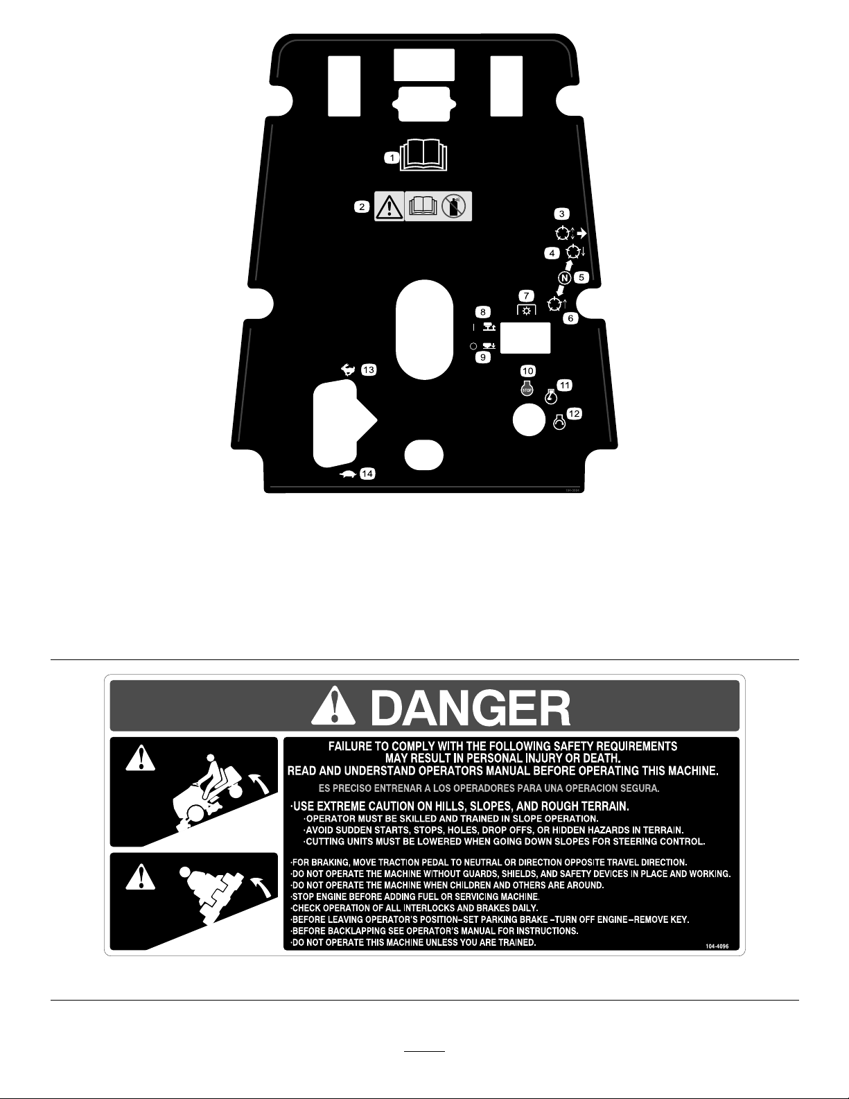
(Afxoverdecalpartno.104–4096forCE)
*Thissafetydecalincludesaslopewarningrequiredonthemachineforcompliance
totheEuropeanLawnMowerSafetyStandardEN836:1997.Theconservative
maximumslopeanglesindicatedforoperationofthismachineareprescribedby
andrequiredbythisstandard.
1.Warning—readtheOperator’sManual.
2.Tippinghazard—donotdrivethemachineonaslope
greaterthan15degrees.
3.Thrownobjecthazard—keepbystandersasafedistance
fromthemachine.
4.Cuttinghazardofhandandfoot—stayawayfrommoving
parts,keepallguardsandshieldsinplace.
5.Warning—locktheparkingbrake,stoptheengine,and
removetheignitionkeybeforeleavingthemachine.
BatterySymbols
Someorallofthesesymbolsareonyourbattery
1.Explosionhazard
2.Nore,opename,or
smoking.
3.Causticliquid/chemical
burnhazard
4.Weareyeprotection9.Flusheyesimmediately
5.ReadtheOperator’s
Manual.
6.Keepbystandersasafe
7.Weareyeprotection;
8.Batteryacidcancause
10.Containslead;donot
distancefromthebattery .
explosivegasescan
causeblindnessandother
injuries
blindnessorsevereburns.
withwaterandgetmedical
helpfast.
discard.
8
Page 9
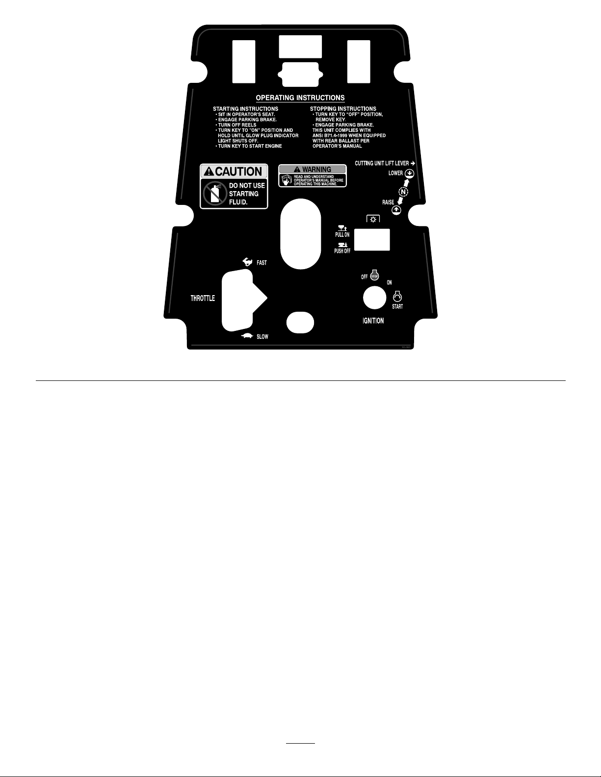
104-3991
9
Page 10
(Afxoverdecalpartno.104–3991forCE)
1.ReadtheOperator’s
Manual.
2.Warning—readthe
Operator’sManual,do
notusestartinguid.
3.Raiseandlowerthereels.
4.Lowerthereels.8.Pullon12.Engine—start
5.Neutral
6.Raisethereels.10.Engine—stop
7.Powertake-off(PTO)
104-3994
9.Pushoff
11.Engine—run
13.Fast
14.Slow
104-4096
10
Page 11
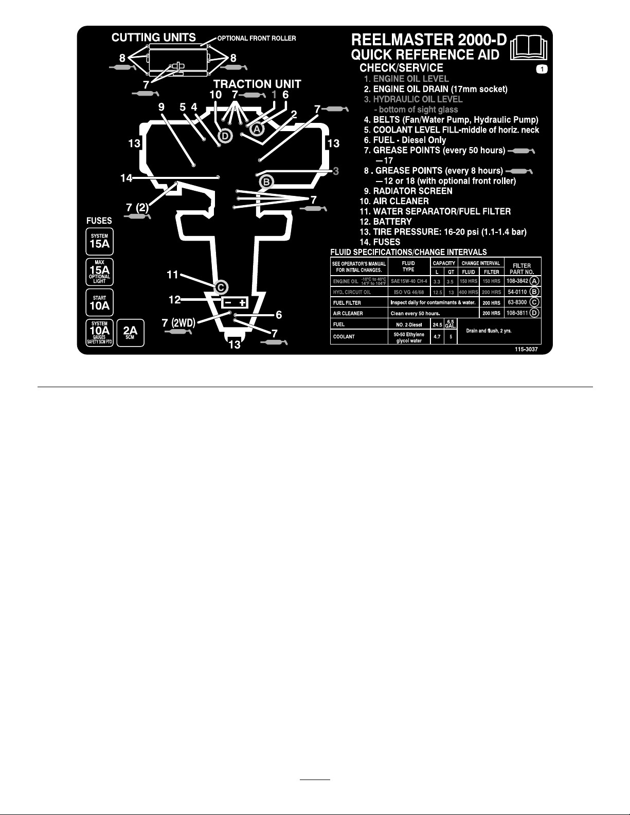
115–3037
11
Page 12

Setup
LooseParts
Usethechartbelowtoverifythatallpartshavebeenshipped.
ProcedureDescription
1
2
3
4
5
6
7
8
Wheelassembly1
Lugnut4
Rearcarrierframe
Washer6
Bolt(3/8x2-1/4inches)
Locknut(3/8inch)
Liftarm
Pivotrod2
Bolt(5/16x7/8inch)
Lockwasher2
Liftchain
Clevispin
Cotterpin
Nopartsrequired
Trustwasher3
Flatwasher3
Flange-headbolt3
Spring
Vinylsleeve1
Springshackle
Clevispin
Cotterpin
Shackle(32inchcuttingunitonly)
Springanchor(32inchcuttingunitonly)
Bolt(1/4x3/4inch)(32inchcuttingunit
only)
Locknut(32inchcuttingunitonly)
Rearweightkit(s)
Varies
Qty.
Use
Installtherearwheel.
1
3
3
2
2
2
4
4
–
3
3
6
6
2
2
4
4
Adjusttherearcarrierframeheight.
Mountthecarrierframestothecutting
units.
Installthefrontliftarms(suppliedinthe
LiftArmKit).
Mountthecuttingunitdrivemotors
(suppliedintheLiftArmKit).
Mountthecuttingunits.
Installthecounterbalancesprings
(suppliedintheliftarmkit).
Addrearballast(orderfromyourT oro
Distributor).
9
10
11
Nopartsrequired
Decal104–39941
Decal106–81191
Nopartsrequired
MediaandAdditionalParts
Description
Key2
Hydraulicreserviorplug1
Qty.
–
–
Startthemachine
Pluggingthehydraulicreservoirduringalterchange.
12
ActivateandChargetheBattery
InstallCECompliantDecals(CEOnly)
Break-inanewmachine
Use
Page 13
Operator’sManual
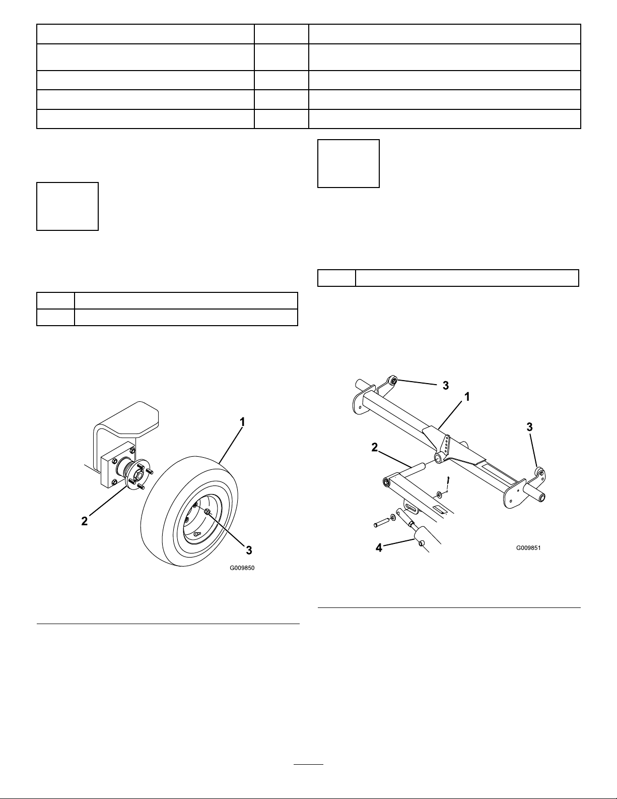
G009850
1
2
3
G009851
1
3
3
2
4
EngineOperator’sManual
Operatortrainingmaterial
Description
Qty.
1
1
1
Readbeforeoperatingthemachine.
Viewbeforeoperatingthemachine.
Use
PartsCatalog
Certicateofcompliance
Note:Determinetheleftandrightsidesofthemachine
fromthenormaloperatingposition.
1
InstallingtheRearWheel
Partsneededforthisprocedure:
1Wheelassembly
4Lugnut
Procedure
1.Mountthewheelassemblyontotherearwheelhub
(Figure2).
1Viewandorderparts.
1
CEcertication
2
AdjustingtheRearCarrier
FrameHeight
Partsneededforthisprocedure:
1
Procedure
1.Slidetherearcarrierframeontotherearliftarm
pivotrod(Figure3).Donotinstallthecarrierframe
tothecuttingunitatthistime.
Rearcarrierframe
Figure3
Figure2
1.Wheelassembly3.Lugnut
2.Rearwheelhub
2.Installthelugnuts(Figure2)andtightenthemto45
to65ft-lb(3to5N-m).
1.Rearcarrierframe
2.Pivotrod
2.Raisetheliftarmsandcarrierframefully.
3.Pressdownononeendofthecarrierframeuntilthe
upstopontheoppositeendcontactstheunderside
ofthefootstep(Figure3).
Thedistancebetweentheupstopandtheunderside
ofthefootstep,ontheendpresseddown,shouldbe
approximately1/4inch(6mm).
13
3.Upstop
4.Liftcylinder
Page 14
•Ifthedistanceiscorrect,removethecarrier
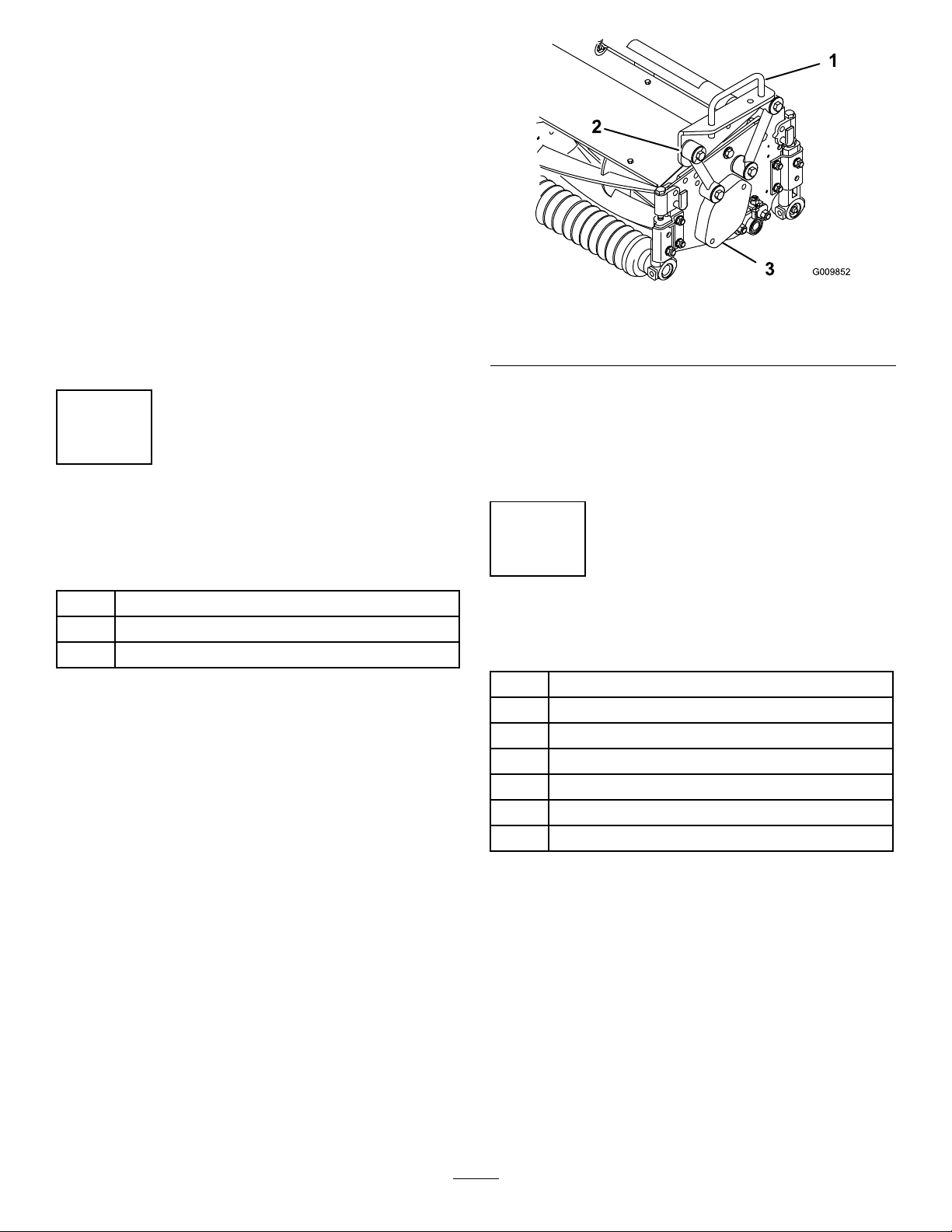
G009852
1
3
2
frameandproceedwiththesetupinstructions.
•Ifthedistanceisnot1/4inch(6mm),adjustthe
liftcylinderasfollows:
A.Removetheclevispinsecuringtherodend
oftheliftcylindertotheliftarm(Figure3).
B.Loosenthehexnutsecuringtheclevistothe
cylinderrod.
C.Rotatetheclevisendinoroutuntilyou
attain1/4inch(6mm)clearance.Checkthe
adjustmentandrepeatsteps2through3as
required.
D.Tightenthehexnutandconnectthecylinder
rodendtotheliftarm(Figure3).
3
MountingtheCarrierFrames
Figure4
1.Carrierframe
2.Mountinglink
3.Secureeachmountinglinktothecarrierframewith
abolt(3/8x2-1/4inches),2washers,andalocknut,
asshowninFigure4.Positionawasheroneach
sideofthelinkwhenmounting.Torqueto31ft-lb
(42N-m).
3.Bearinghousingcover
totheCuttingUnits
Partsneededforthisprocedure:
6Washer
3
Bolt(3/8x2-1/4inches)
3
Locknut(3/8inch)
Procedure
1.Removethecuttingunitsfromthecartons.Adjust
thempertheCuttingUnitOperator’ sManual.
2.Positionacarrierframeontoeachcuttingunit,
aligningthemountingholeswiththemountinglinks
(Figure4).
4
InstallingtheFrontLiftArms
Partsneededforthisprocedure:
2
Liftarm
2Pivotrod
2
Bolt(5/16x7/8inch)
2Lockwasher
2
Liftchain
4
Clevispin
4
Cotterpin
Procedure
1.Insertapivotrodintotheleftliftarmandalignthe
mountingholes(Figure5).
14
Page 15
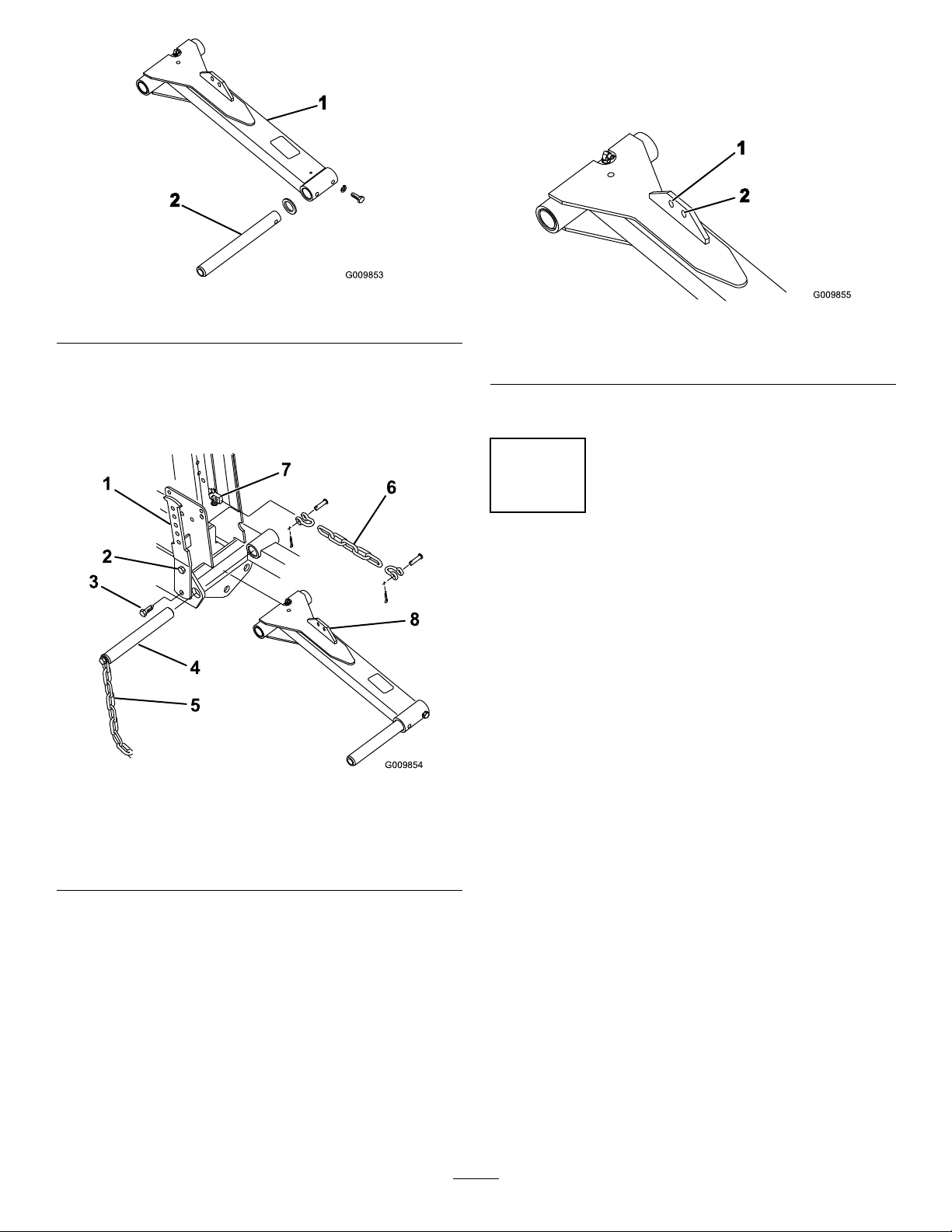
G009853
1
2
Figure5
G009854
1
2
3
4
5
8
6
7
G009855
2
1
1.Liftarm
2.Pivotrod
2.Securethepivotrodtotheliftarmwithabolt(5/16
x7/8inch)andlockwasher.
3.Loosenthetopboltsecuringtheleftcounterbalance
armtotheframe(Figure6).
8.Securetheotherendoftheliftchaintothehole
intheliftarmmountingtabwithclevispinsand
cotterpins.Usetheappropriateholeintheliftarm
asdesignatedinFigure7.
Figure7
1.27inchcuttingunit(inner
hole)
2.32inchcuttingunit(outer
hole)
9.Repeattheprocedureontheright-handliftarm.
5
MountingtheCuttingUnit
DriveMotors
NoPartsRequired
Procedure
1.Positionthecuttingunitsinfrontofthepivotrods.
2.Removethebearinghousingcover(Figure4)from
theinsideendoftheright-handcuttingunit.Install
Figure6
1.Counterbalancearm
2.Topbolt
3.Bottombolt
4.Liftarmpivotpin8.Liftarmtab
5.Tipperchain
6.Liftchain
7.Cylinderpin
4.Removethebottomboltandnutsecuringtheleft
counterbalancearmtotheframe(Figure6).
5.Rotatethecounterbalancearmoutwardandremove
theliftarmpivotpinandtipperchain(Figure6).
6.Positiontheliftarmbetweentheframemembers,
alignthemountingholes,andinstallthepivot
pin(Figure6).Insertthepivotpinsothatthe
counterbalancearmtsintotheslotinthepin.Do
notsecurethecounterbalancearmatthistime.
7.Secureoneendoftheliftchaintotheliftcylinder
pinwithaclevispinandcotterpin.
15
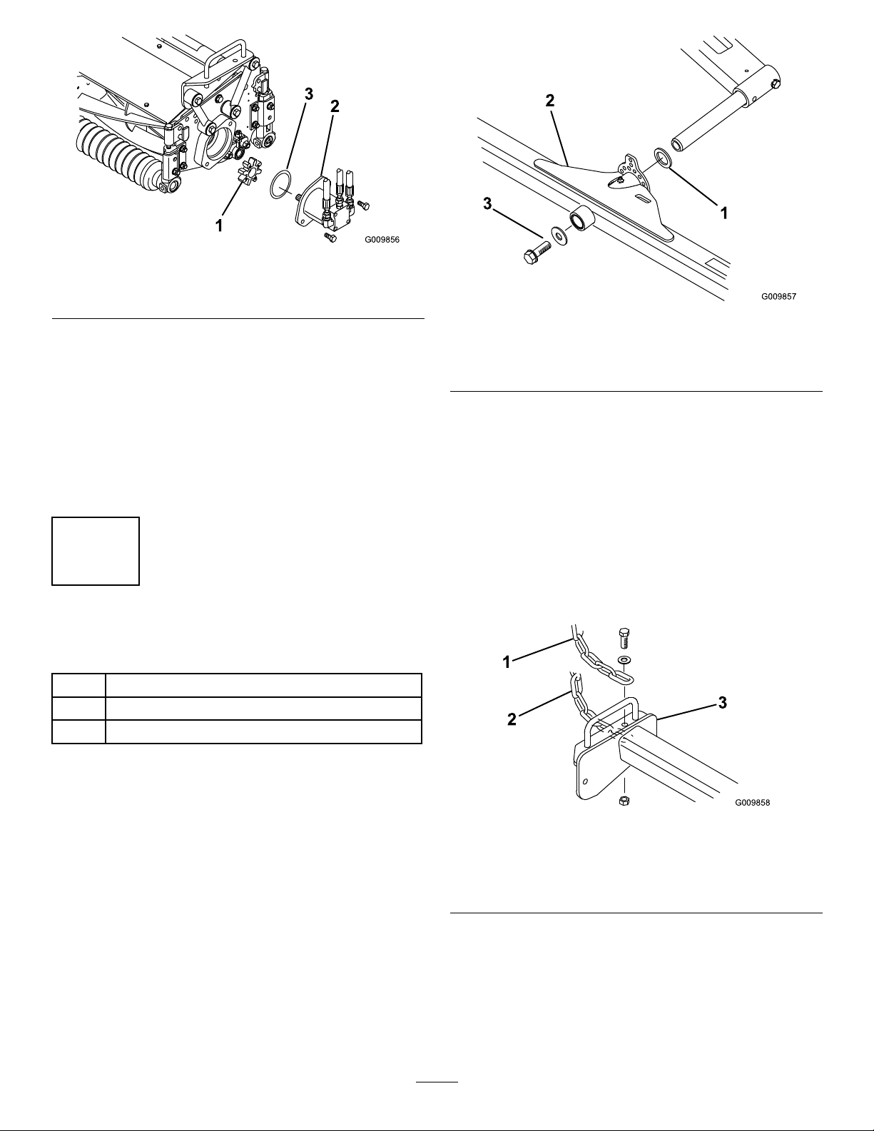
thecoverandgasket(suppliedwiththecuttingunit)
ontheoutsideend.Locatethespidercoupling
(Figure8)shippedinthebearinghousing.
Page 16
G009856
1
2
3
Figure8
G009857
1
2
3
G009858
1
2
3
1.Spidercoupling3.O-ring
2.Reelmotor
3.InserttheO-ring(suppliedwiththecuttingunit)on
theangeofthedrivemotor(Figure8).
4.Mountthemotorandthespidercouplingtothe
driveendofthecuttingunitandsecurethemwith2
boltsprovidedwiththecuttingunit(Figure8).
5.Onthecenterandleft-handcuttingunits,remove
thebearinghousingcoverandinstallthegasket
(suppliedwiththecuttingunits).
6
MountingtheCuttingUnits
Partsneededforthisprocedure:
Figure9
1.Thrustwasher3.Flatwasherand
ange-headbolt
2.Carrierframe
2.Slidethecuttingunitcarrierframeontothepivot
rodandsecureitwithaatwasherandange-head
bolt(Figure9).
Note:Ontherearcuttingunit,positionthethrust
washerbetweentherearofthecarrierframeandthe
atwasher.
3.Secureatipperchaintothetopofeach27inch
cuttingunitcarrierframeandtothebottomofeach
32inchcuttingunitcarrierframewithabolt,washer,
andlocknut(Figure10).
3Trustwasher
3Flatwasher
3Flange-headbolt
Procedure
1.Slideathrustwasherontotheliftarmpivotrod
(Figure9).
1.Tipperchain(27inch
cuttingunits)
2.Tipperchain(32inch
cuttingunits)
4.Greaseallliftarmandcarrierframepivotpoints.
16
Figure10
3.Carrierframe
Page 17
7
G009859
1
InstallingtheCounterbalance
Springs
Partsneededforthisprocedure:
3
Spring
1Vinylsleeve
3
Springshackle
6
Clevispin
6
Cotterpin
2
Shackle(32inchcuttingunitonly)
2
Springanchor(32inchcuttingunitonly)
4
Bolt(1/4x3/4inch)(32inchcuttingunitonly)
4
Locknut(32inchcuttingunitonly)
Note:Selectingthe#4holeposition(increasing
thespringtension)willreducetheweightonthe
inboardendofthecuttingunit,increasetheweight
ontheoutboardendofthecuttingunit,andincrease
traction.Selectingthe#2holepositionhasthe
oppositeaffect.
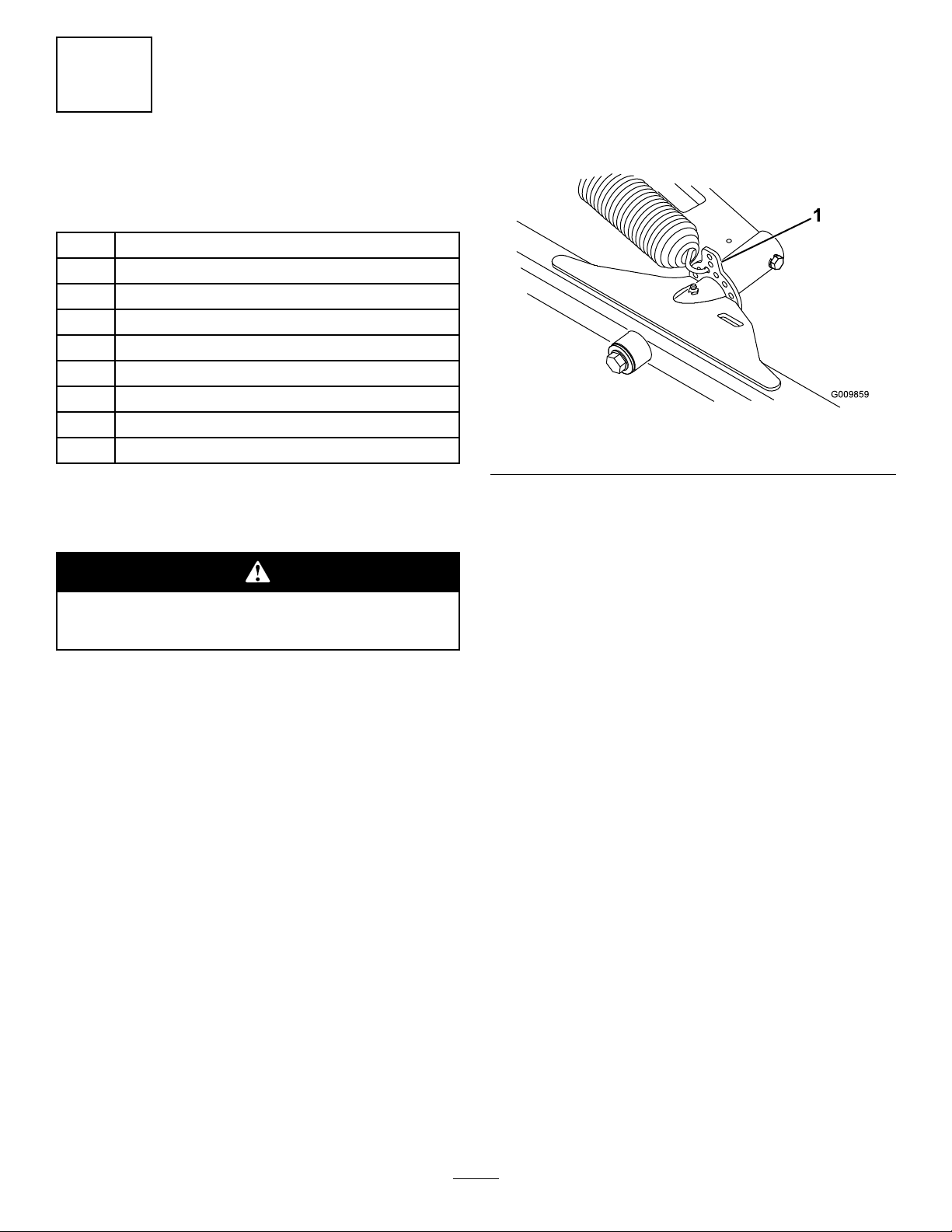
Figure11
1.Cuttingunitlifttab
PrecautionsandSettingsforthe
CounterbalanceSprings
Usecautionwhentensioningthespringsas
theyareunderheavyload.
Thecounterbalancespringshelpbalancethecutting
unitstoallowequalamountsofweight(downpressure)
tobedistributedtoeachendofthecuttingunit.The
springsalsotransferweightfromthecuttingunitstothe
tractionunit,thereforeincreasingtraction.
Thesettingsrecommendedinthefollowingprocedures
mayberequireminorchangestoachieveoptimum
performanceforyourturfconditions.Theweight,at
eachendofthecuttingunit,canbecheckedeasilywitha
springscale.
•Increasingthespringtensionreducestheweight
oninboardendofthecuttingunitandincreases
theweightontheoutboardend.
•Decreasingthespringtensionincreasestheweight
ontheinboardendofthecuttingunitandreduces
theweightonoutboardend.
2.Securetheotherendofthespringtotheappropriate
hole(seebelow)onthefrontandrearcounterbalance
arms(Figure12andFigure13)withthespring
shackle,clevispin,andcotterpin.
•5bladereels—fourthholefromthetop
•8bladereels—thirdholefromthetop
•Reelswithbaskets—tophole
Note:Ontherearcounterbalancespring,installthe
vinylcoveroverthespringbeforeinstalling.
Note:Increasingthespringtensionwillreduce
theweightontheinboardendofthecuttingunit,
increasetheweightontheoutboardendofthe
cuttingunit,andincreasetraction.Decreasingthe
springtensionhastheoppositeeffect.
InstallingtheCounterbalanceSprings
on27InchCuttingUnits
1.Hookthespringintothethirdholefromthetopon
theinboardsideofbothfrontcuttingunitlifttabs
andontherearcuttingunitlifttab(Figure11).
17
Page 18

Figure12
G009862
1
2
1.Counterbalancearm4.Springshackle
2.Topbolt
3.Bottombolt
5.Clevispinandcotterpin
InstallingtheCounterbalanceSprings
on32InchCuttingUnits
1.Mountaspringanchortotherearinboardsideof
eachfrontcuttingunitlifttabwith2bolts(1/4x3/4
inch)andlocknuts,asshowninFigure14.
Figure14
1.Cuttingunitlifttab2.Springanchor
2.Onthefrontcuttingunits,hookthespringintothe
secondholefromthebottom(#3position)inthe
springanchor(Figure14).
Figure13
1.Rearcounterbalance
spring
2.Vinylcover
3.Springshackle
3.Insertthebreakerbarintothesquareholeinthe
counterbalancearmandpivotthearmbacktoits
originalposition,aligningthemountingholes.
4.Securethebottomofthecounterbalancearmtothe
framewiththeboltandnutpreviouslyremoved.
Tightenthetopbolt(Figure12).
5.Totensionthecounterbalancesprings,proceedas
follows:
A.Removethecotterpinandclevispinsecuringthe
springshackletothecounterbalancearm.Do
notremovetheotherclevispin.
B.Movetheshackleupordownonthe
counterbalancearmuntilitisalignedwiththe
desiredholeonthearm.Installtheclevispin
andcotterpin.
Note:Selectingthe#4holeposition(increasing
thespringtension)willreducetheweightonthe
inboardendofthecuttingunit,increasetheweight
ontheoutboardendofthecuttingunit,andincrease
traction.Selectingthe#2holepositionhasthe
oppositeaffect.
3.Ontherearcuttingunit,hookthespringintothetop
holeontherearcuttingunitlifttab.
Note:Increasingthespringtensionwillreduce
theweightontheinboardendofthecuttingunit,
increasetheweightontheoutboardendofthe
cuttingunit,andincreasetraction.Decreasingthe
springtensionhastheoppositeaffect.
4.Securetheotherendofthespringtotheappropriate
hole(seebelow)onthefrontandrearcounterbalance
arms(Figure15andFigure16)withthespring
shacklewiththechain,clevis,clevispin,andcotter
pin.
•5bladereels—thirdholefromthetop
•8bladereels—secondholefromthetop
•Reelswithbaskets—tophole
Note:Onrearcounterbalancespring,installthe
vinylcoveroverthespringbeforeinstalling.
18
Page 19

Figure15
1.Counterbalancearm4.Springshackle
2.Topbolt
3.Bottombolt
5.Clevispinandcotterpin
6.Chain,clevis,andclevis
B.Movetheshackleupordownonthe
counterbalancearmuntilitisalignedwiththe
desiredholeonthearm.Installtheclevispin
andcotterpin.
8
AddingRearBallast
Partsneededforthisprocedure:
pin
Varies
Procedure
ThisunitcomplieswithANSlB71.4–2004Standardsand
allapplicableEuropeanrequirementswhenequipped
withrearballast.Usethefollowingcharttodetermine
theweightorcombinationsofweightsneeded.
Rearweightkit(s)
Figure16
1.Rearcounterbalance
spring
2.Vinylcover
3.Springshackle
5.Securetheotherendofthespringtothesecondhole
fromthetopwiththespringshacklewiththechain,
clevis,clevispin,andcotterpin(Figure15).
6.Ontherearcounterbalancearms,installthevinyl
coveroverthespringbeforehookingtheotherend
ofthespringintothespringshackleinthesecond
holefromthetop(Figure16).
7.Insertthebreakerbarintothesquareholeinthe
counterbalancearmandpivotthearmbacktoits
originalposition,aligningthemountingholes.
8.Securethebottomofthecounterbalancearmtothe
framewiththeboltandnutpreviouslyremoved.
Tightenthetopbolt(Figure15).
CuttingUnitConguration
Standardmachinewith27inch
cuttingunits
Standardmachinewith27inch
cuttingunits&baskets
Standardmachinewiththree
wheeldrivekit&27inch
cuttingunits
Standardmachinewiththree
wheeldrivekit,27inchcutting
units&baskets
Standardmachinewith32inch
cuttingunits
Standardmachinewith32inch
cuttingunits&threewheel
drivekit
WeightKitsRequired
(1)83-9370
(2)83-9390
(1)83-9370(3)83-9390
(2)94-3698
(1)83-9390
(1)83–9370
(2)83-9390(2)94-3698
(1)83–9370
(3)83-9390(2)94-3698
(1)83–9370
(1)83-9370(2)83-9390
(1)94–3698
Note:Allcongurationsrequirecalciumchlorideinthe
reartire.Thetireshouldbelledtoapproximately75%
capacity(levelwiththevalveatthetop)(60lb(27kg)
uidor74lb(33.5kg)tireanduid).
Important:Ifapunctureoccursinatirewith
calciumchloride,removetheunitfromtheturfarea
asquicklyaspossible.T opreventpossibledamage
totheturf,immediatelysoaktheaffectedareawith
water.
9.Totensionthecounterbalancespringsproceedas
follows:
A.Removethecotterpinandclevispinsecuringthe
springshackletothecounterbalancearm.Do
notremovetheotherclevispin.
EitherType1(77%)orType2(94%)commercial
calciumchlorideakemaybeused.
Plainwaterfreezessolidat32°F(0°C).The3-1/2lb.
(1.6kg)calciumchlorideto1gallon(3.8l)ofwater
19
Page 20

solutionisslushfreeto-12°F(-24°C)andwillfreeze
solidat-52°F(-46°C).The5lb.(2.3kg)pergallon(liter)
solutionisslushfreeto-50°F(-45°C)andwillfreeze
solidat-62°F(-52°C).
Chargingthebatteryproducesgassesthatcan
explode.
Neversmokenearthebatteryandkeepsparks
andamesawayfrombattery.
9
ActivatingandChargingthe
Battery
NoPartsRequired
Procedure
Warning
CALIFORNIA
Proposition65Warning
Batteryposts,terminals,andrelated
accessoriescontainleadandleadcompounds,
chemicalsknowntotheStateofCalifornia
tocausecancerandreproductiveharm.
Washhandsafterhandling.
Ifthebatteryisnotlledwithelectrolyteoractivated,
bulkelectrolytewith1.260specicgravitymustbe
purchasedfromalocalbatterysupplyoutletandadded
tothebattery.
1.Removethellercapsfromthebatteryandslowlyll
eachcelluntiltheelectrolyteisjustabovetheplates.
3.Whenthebatteryischarged,disconnectthecharger
fromtheelectricaloutletandbatteryposts.
4.Removethellercaps.Slowlyaddelectrolyteto
eachcelluntilthelevelisuptothellring.Install
thellercaps.
Important:Donotoverllthebattery.
Electrolytewilloverowontootherpartsofthe
machineandseverecorrosionanddeterioration
willresult.
5.Installthepositivecable(red)tothepositive(+)
terminalandthenegativecable(black)tothe
negative(-)terminalofthebatteryandsecurethem
withboltsandnuts.Slidetherubberbootoverthe
positiveterminaltopreventapossibleshortfrom
occurring.
Incorrectbatterycableroutingcoulddamage
themachineandcablescausingsparks.Sparks
cancausethebatterygassestoexplode,
resultinginpersonalinjury.
•Always
batterycablebeforedisconnectingthe
positive(red)cable.
disconnect
thenegative(black)
Batteryelectrolytecontainssulfuricacidwhich
isadeadlypoisonandcausessevereburns.
•Donotdrinkelectrolyteandavoidcontact
withskin,eyesorclothing.Wearsafety
glassestoshieldyoureyesandrubbergloves
toprotectyourhands.
•Fillthebatterywherecleanwaterisalways
availableforushingtheskin.
2.Replacethellercapswiththeventspointingto
therear(towardthefueltank)andconnecta3to4
ampbatterychargertothebatteryposts.Chargethe
batteryatarateof3to4amperesfor4to8hours.
•Always
cablebeforeconnectingthenegative(black)
cable.
20
connect
thepositive(red)battery
Page 21

ProductOverview
10
InstallingCECompliantDecals
Partsneededforthisprocedure:
1Decal104–3994
1Decal106–81 19
Procedure
IfyouaresettingupthisunitforuseintheEuropean
Union(CE),installtheCEcompliantdecalsovertheir
UScounterpartsasfollows:
Note:RefertoSafetyandInstructionalDecalsfor
illustrationsofthesedecals.
1.Installdecal104-3994overdecal104-3991.
2.Installdecal106-8119overdecal104-4096.
Controls
TractionandStoppingPedal
Thetractionpedal(Figure17)hasthreefunctions:to
makethemachinemoveforward,tomoveitbackward,
andtostopthemachine.Usingtheheelandtoeofthe
rightfoot,pressthetopofthepedaltomoveforward
andthebottomofthepedaltomovebackwardorto
assistinstoppingwhenmovingforward(Figure18).
Also,allowthepedaltomoveormoveittotheneutral
positiontostopthemachine.Donottherestheelof
yourfootonreversewhenoperatingforward.
11
Breaking-inaNewMachine
NoPartsRequired
Procedure
Whentheengineisstartedforthersttime,orafter
overhaulingtheengine,operatethemachineinforward
andreverseforonetotwominutes.Alsooperatethelift
leverandreeldriveswitchtobesureofproperoperation
ofallparts.
Turnthesteeringwheeltotheleftandrighttocheck
thesteeringresponse.Thenshuttheengineoffand
checkforoilleaks,looseparts,andanyothernoticeable
malfunctions.
Shuttheengineoffandwaitforallmoving
partstostopbeforecheckingforoilleaks,loose
parts,andothermalfunctions.
Figure17
1.Tractionpedal3.Pedalstop
2.Speedselector
Figure18
SpeedSelector
Thespeedselectorisacamleveratthesideofthe
tractionpedal(Figure17)thatcanberotatedtomaintain
desiredspeed.Thereversepedalstop(underthepedal)
21
Page 22

(Figure17)issetatthefactorytoprovide3MPH
maximumspeedinreverse.
StarterSwitch
CuttingUnitLiftLeverLock
Thecuttingunitliftleverlock(Figure19)lockscutting
unitsintheraisedpositionfortransporting.
Thestarterswitch(Figure19),usedtostart,stop,and
preheattheengine,hasthreepositions:Off,On,and
Start.RotatethekeyclockwisetotheOnpositionand
holdituntiltheglowpluglightgoesout.Thenrotate
thekeyclockwisetotheStartpositiontoengagethe
startermotor.Releasethekeywhentheenginestarts.
ThekeywillmoveautomaticallytotheOnposition.To
shuttheengineoff,rotatethekeycounterclockwiseto
theOffposition.Removethekeyfromtheswitchto
preventaccidentalstarting.
CuttingUnitDriveSwitch
Theswitch(Figure19)hastwopositions:Engageand
Disengage.Thepush-pullswitchoperatesasolenoid
valveonthevalvebank,todrivethecuttingunits.
HourMeter
Thehourmeter(Figure20)indicatesthetotalhoursof
machineoperation.Thehourmeterstartstofunction
wheneverthekeyswitchisrotatedtotheOnposition.
Figure19
1.Starterswitch4.Cuttingunitliftlever
2.Throttle
3.Cuttingunitdriveswitch
5.Cuttingunitliftleverlock
Throttle
Movingthethrottle(Figure19)upwardincreasesthe
enginespeedanddownwarddecreasestheenginespeed.
CuttingUnitLiftLever
Theliftlever(Figure19)hasthreepositions:Lower,
Raise,andNeutral.Tolowerthecuttingunitstothe
ground,movetheliftleverforward.Whenloweringthe
cuttingunits,makesurethatthefronthydrauliccylinder
iscompletelyretractedbeforereleasingtheliftlever.
Thecuttingunitswillnotoperateunlessthecylinderis
retracted.Toraisethecuttingunits,pulltheliftlever
rearwardtotheRaiseposition.
Figure20
1.Oilpressurelight4.Glowplugindicatorlight
2.Alternatorlight5.Hourmeter
3.Highwatertemperature
shut-downlight
6.Reeloperatinglight
OilPressureLight
Theoilpressurelight(Figure20)glowsiftheengineoil
pressuredropsbelowasafelevel.
WaterTemperatureLight
Thewatertemperaturelight(Figure20)glowsand
theengineautomaticallyshutsdownwhentheengine
coolanttemperaturegetstoohigh.
AlternatorLight
Thealternatorlight(Figure20)shouldbeoffwhen
theengineisrunning.Ifitison,checkandrepairthe
chargingsystemasnecessary.
22
Page 23

GlowPlugIndicator
G009878
1
2
Theindicatorlight(Figure20)willglowwhenglow
plugsareoperating.
ReelEngageIndicator
Thereelengageindicatorlight(Figure20)willglow
whenreelsareloweredtocuttingposition.
ParkingBrake
Whenevertheengineisshutoff,engagetheparking
braketopreventaccidentalmovementofthemachine.
Toengagetheparkingbrake,pullbackonthelever.
ReelSpeedControl
Toobtainthedesiredcliprate(reelspeed),rotatethe
reelspeedcontrolknob(Figure21)totheappropriate
settingfortheheight-of-cutsettingandmowerspeed.
RefertoSettingtheReelSpeed.
Figure21
1.Reelspeedcontrol2.Backlapcontrol
BacklapControl
Rotatetheknob(Figure21)toRforbacklappingandto
Fformowing.Donotchangetheknobpositionwhen
thereelsarerotating.
Figure22
1.Fuelshut-off(underthefueltank)
Specications
Note:Specicationsanddesignaresubjecttochange
withoutnotice.
Transportwidthwith27inch
cuttingunits
Transportwidthwith32inch
cuttingunits
Widthofcut76-1/2inches(194cm)
Length
Heightwithouttheseat
NetWeight(withoutcutting
units)
Attachments/Accessories
AselectionofToroapprovedattachmentsand
accessoriesareavailableforusewiththemachineto
enhanceandexpanditscapabilities.Contactyour
AuthorizedServiceDealerorDistributororgoto
www.Toro.comforalistofallapprovedattachments
andaccessories.
72inches(183cm)
85inches(216cm)
96inches(244cm)
44inches(112cm)
1,250lbs.(567kg)
SeatAdjustment
Movetheleveronthesideoftheseatoutward,slidethe
seatforwardorrearwardtothedesiredposition,and
releasethelevertolocktheseatintoposition.
FuelShut-OffValve
Closethefuelshut-offvalve,underthefueltank
(Figure22),whenstoringthemachine.
23
Page 24

Operation
Note:Determinetheleftandrightsidesofthe
machinefromthenormaloperatingposition.
Ifyouleavethekeyintheignitionswitch,
someonecouldaccidentlystarttheengineand
seriouslyinjureyouorotherbystanders.
Lowerthecuttingunitstotheground,setthe
parkingbrake,andremovethekeyfromthe
ignitionswitchbeforeservicingormaking
adjustmentstothemachine.
CheckingtheEngineOilLevel
ServiceInterval:Beforeeachuseordaily
Theengineisshippedwithoilinthecrankcase;
however,theoillevelmustbecheckedbeforeandafter
theengineisrststarted.
Crankcasecapacityisapproximately3.5qt.(3.3l)with
thelter.
Usehigh-qualityengineoilthatmeetsthefollowing
specications:
•APIClassicationLevelRequired:CH-4,CI-4or
higher
•Preferredoil:SAE15W-40(above0°F/-18°C)
Figure23
1.Dipstick
3.Removethedipstickandchecktheoillevelonthe
dipstick.
TheoillevelshouldbeuptotheFullmark.
4.IftheoillevelisbelowtheFullmark,removethe
llcap(Figure24)andaddoiluntilthelevelreaches
theFullmarkonthedipstick.Donotoverll.
Important:Besuretokeeptheengineoillevel
betweentheupperandlowerlimitsontheoil
gauge.Enginefailuremayoccurasaresultof
overllingorunderllingtheengineoil.
•Alternateoil:SAE10W-30or5W -30(all
temperatures)
ToroPremiumEngineoilisavailablefromyour
distributorineither15W-40or10W -30viscosity .
1.Parkthemachineonalevelsurface,stoptheengine,
settheparkingbrake,andremovethekeyfromthe
ignitionswitch.
2.Removethedipstick,wipeitclean,andinstallit,
ensuringthatitisfullyseated(Figure23).
Figure24
1.Oilllcap
Important:Whenaddingengineoilorlling
oil,theremustbeclearancebetweentheoilll
deviceandtheoilllholeinthevalvecoveras
showninFigure25.Thisclearanceisnecessary
topermitventingwhenlling,whichprevents
oilfromoverrunningintothebreather.
24
Page 25

Figure25
1.Clearance
5.Installthedipstickandtheoilllcap.Closethe
hood.
6.Startandruntheengineatidlefor30seconds.Shut
theengineoff.Wait30secondsandchecktheoil
level.Ifneeded,addoiltoraisetheleveltotheFull
markonthedipstick.
Fuelisharmfulorfatalifswallowed.Long-term
exposuretovaporscancauseseriousinjuryand
illness.
•Avoidprolongedbreathingofvapors.
•Keepfaceawayfromnozzleandfueltankor
conditioneropening.
•Keepfuelawayfromeyesandskin.
BiodieselReady
Thismachinecanalsouseabiodieselblendedfuel
ofuptoB20(20%biodiesel,80%petrodiesel).The
petrodieselportionshouldbeloworultralowsulfur.
Observethefollowingprecautions:
•Thebiodieselportionofthefuelmustmeet
specicationASTMD6751orEN14214.
•TheblendedfuelcompositionshouldmeetASTM
D975orEN590.
•Paintedsurfacesmaybedamagedbybiodiesel
blends.
•UseB5(biodieselcontentof5%)orlesserblends
incoldweather.
AddingFuel
Useonlyclean,freshdieselfuelorbiodieselfuelwith
low(<500ppm)orultralow(<15ppm)sulfurcontent.
Theminimumcetaneratingshouldbe40.Purchase
fuelinquantitiesthatcanbeusedwithin180daysto
ensurefuelfreshness.
Fueltankcapacity:6.5gallons(24.6l)
Usesummergradedieselfuel(No.2-D)attemperatures
above20°F(-7°C)andwintergrade(No.1-Dor
No.1-D/2-Dblend)belowthattemperature.Useof
wintergradefuelatlowertemperaturesprovideslower
ashpointandcoldowcharacteristicswhichwillease
startingandreducefuellterplugging.
Useofsummergradefuelabove20°F(-7°C)will
contributetowardlongerfuelpumplifeandincreased
powercomparedtowintergradefuel.
Important:Donotusekeroseneorgasoline
insteadofdieselfuel.Failuretoobservethis
cautionwilldamagetheengine.
•Monitorseals,hoses,gasketsincontactwithfuelas
theymaybedegradedovertime.
•Fuellterpluggingmaybeexpectedforatimeafter
convertingtobiodieselblended.
•Contactyourdistributorifyouwishformore
informationonbiodiesel.
25
Page 26

Incertainconditions,fuelisextremely
ammableandhighlyexplosive.Areor
explosionfromfuelcanburnyouandothers
andcandamageproperty.
•Fillthefueltankoutdoors,inanopenarea,
whentheengineiscold.Wipeupanyfuel
thatspills.
•Neverllthefueltankinsideanenclosed
trailer.
•Neversmokewhenhandlingfuel,andstay
awayfromanopenameorwherefuel
fumesmaybeignitedbyaspark.
•Storefuelinanapprovedcontainerandkeep
itoutofthereachofchildren.Neverbuy
morethana30-daysupplyoffuel.
Note:Ifpossible,llthefueltankaftereachuse.This
willminimizepossiblebuildupofcondensationinside
thefueltank.
1.Parkthemachineonalevelsurface.
2.Usingacleanrag,cleantheareaaroundthefuel
tankcap.
3.Removethecapfromthefueltank(Figure26).
•Donotoperatewithoutentireexhaust
systeminplaceandinproperworking
condition.
Incertainconditionsduringfueling,static
electricitycanbereleasedcausingaspark
whichcanignitethefuelvapors.Areor
explosionfromfuelcanburnyouandothers
andcandamageproperty.
•Alwaysplacefuelcontainersontheground
awayfromyourvehiclebeforelling.
•Donotllfuelcontainersinsideavehicle
oronatruckortrailerbedbecauseinterior
carpetsorplastictruckbedlinersmay
insulatethecontainerandslowthelossof
anystaticcharge.
•Whenpractical,removeequipmentfromthe
truckortrailerandrefueltheequipment
withitswheelsontheground.
•Ifthisisnotpossible,thenrefuelsuch
equipmentonatruckortrailerfroma
portablecontainer,ratherthanfromafuel
dispensernozzle.
Figure26
1.Fueltankcap
4.Fillthetanktoabout1inch(25mm)belowthe
topofthetank(bottomofthellerneck).Donot
overll.
5.Installthefueltankcaptightly.
6.Wipeupanyfuelthatmayhavespilledtopreventa
rehazard.
CheckingtheCoolingSystem
ServiceInterval:Beforeeachuseordaily
Cleandebrisoffofthescreen,oilcooler,andfront
oftheradiatordailyandmoreoftenifconditionsare
extremelydustyanddirty.RefertoRemovingDebris
fromtheCoolingSystem.
Thecoolingsystemislledwitha50/50solution
ofwaterandpermanentethyleneglycolantifreeze.
Checkthelevelofcoolantintheexpansiontankatthe
beginningofeachdaybeforestartingtheengine.The
capacityofthecoolingsystemis5.25quarts(5l).
•Ifafueldispensernozzlemustbeused,keep
thenozzleincontactwiththerimofthefuel
tankorcontaineropeningatalltimesuntil
fuelingiscomplete.
26
Page 27

3.Ifthecoolantlevelislow,replenishthesystem.Do
notoverll.
Iftheenginehasbeenrunning,thepressurized,
hotcoolantcanescapeandcauseburns.
•Donotopentheradiatorcapwhenthe
engineisrunning.
•Usearagwhenopeningtheradiatorcap,
andopenthecapslowlytoallowsteamto
escape.
1.Carefullyremovetheradiatorcap(Figure27).
Figure27
1.Radiatorcap
2.Checkthelevelofcoolantintheradiatorand
expansiontank(Figure28).
Theradiatorshouldbelledtothemiddleofthe
horizontalllerneck.Theexpansiontankshould
belledhalfwaybetweentheFullandLowmarks.
4.Installtheradiatorandexpansiontankcaps.
CheckingtheHydraulicFluid
ServiceInterval:Beforeeachuseordaily
Thehydraulicreservoirislledatthefactorywith
approximately3.3USgallons(12.5l)ofhighquality
hydraulicuid.Checkthelevelofthehydraulic
uidbeforetheengineisrststartedanddaily
thereafter.Therecommendedreplacementuidisas
follows:
ToroPremiumAllSeasonHydraulicFluid(Availablein
5gallonpailsor55gallondrums.Seethepartscatalogor
yourT orodistributorforpartnumbers.)
Alternateuids:IftheT orouidisnotavailable,other
uidsmaybeusedprovidedtheymeetallthefollowing
materialpropertiesandindustryspecications.Toro
doesnotrecommendtheuseofsyntheticuid.Consult
withyourlubricantdistributortoidentifyasatisfactory
product.
Note:Torowillnotassumeresponsibilityfordamage
causedbyimpropersubstitutions,souseonlyproducts
fromreputablemanufacturerswhowillstandbehind
theirrecommendation.
HighViscosityIndex/LowPourPointAnti-wearHydraulic
Fluid,ISOVG46
MaterialProperties:
Viscosity,ASTMD445cSt@40°C44to48
ViscosityIndexASTM
D2270
PourPoint,ASTMD97-34°Fto-49°F
IndustrySpecications:
VickersI-286-S(QualityLevel),VickersM-2950-S
(QualityLevel),DenisonHF-0
cSt@100°C7.9to8.5
140to160
1.Expansiontank
Figure28
Note:Manyhydraulicuidsarealmostcolorless,
makingitdifculttospotleaks.Areddyeadditive
forthehydraulicsystemoilisavailablein2/3oz.(20
ml)bottles.Onebottleissufcientfor4-6gal(15-22
l)ofhydraulicoil.Orderpartno.44-2500fromyour
authorizedTorodistributor.
BiodegradableHydraulicFluid-Mobil224H
ToroBiodegradableHydraulicFluid(Availablein5
gallonpailsor55gallondrums.SeepartscatalogorT oro
distributorforpartnumbers.)
Alternateuid:MobilEAL224H
Note:Thisisvegetable-oilbasedbiodegradable
oiltestedandapprovedbyT oroforthismodel.
Thisuidisnotasresistanttohightemperaturesas
standarduid,sobesuretofollowtherecommended
uidchangeintervalswiththisuid.Contamination
27
Page 28

bymineral-basedhydraulicuidswillchangethe
biodegradabilityandtoxicityofthisoil.Whenchanging
fromstandarduidtothebiodegradabletype,be
certaintofollowtheapprovedushingprocedure.
ContactyourlocalToroDistributorfordetails.
1.Positionthemachineonalevelsurface,lowerthe
cuttingunits,andstoptheengine.
Note:Thetiresareover-inatedforshipping.
Therefore,releasesomeoftheairtoreducethepressure
beforeusingthemachineforthersttime.
CheckingtheReeltoBedknife
Contact
2.Checktheuidlevelbyviewingitinthesightgauge
(Figure29).
Iftheuidiscold,thelevelshouldbeatthebottom
ofthegauge.Iftheuidishot,thelevelshouldbe
atthecenterofthegauge.
Figure29
1.Hydraulicreservoircap
3.Topreventsystemcontamination,cleanthetopof
thehydraulicuidcontainersbeforepuncturing.
Ensurethatthepourspoutandfunnelareclean.
Also,cleanaroundthehydraulicreservoircap.
2.Sightgauge
ServiceInterval:Beforeeachuseordaily
Eachdaybeforeoperating,checkreeltobedknife
contact,regardlessifthequalityofcuthadpreviously
beenacceptable.Theremustbelightcontactacross
thefulllengthofthereelandthebedknife(referto
AdjustingtheReeltoBedknifeinthecuttingunit
Operator’sManual).
ChecktheTorqueoftheWheel
Nuts
ServiceInterval:Afterthersthour
Aftertherst10hours
Every250hours
Torquethewheellugnutsto45to65ft-lb(61to88
N-m).
Failuretomaintainpropertorqueofthewheel
nutscouldresultinpersonalinjury.
4.Iftheuidlevelisnotatleastatthebottomofthe
gaugewhenitiscold,removethecapfromthe
hydraulicuidreservoir(Figure29)andslowlyll
thereservoirwithhighqualityhydraulicuiduntil
thelevelinitreachesthebottomofthesightgauge.
Donotoverll.
5.Installthereservoircap.Wipeupanyuidthatmay
havespilled.
CheckingtheTirePressure
ServiceInterval:Beforeeachuseordaily
Checktoensurethattheairpressureinthetiresis
16–20psi(110–138kPa).
Important:Maintaintherecommendedpressure
inalltirestoensureagoodquality-of-cut
andpropermachineperformance.
under -inate.
Do not
BleedingtheFuelSystem
Bleedthefuelsystembeforestartingtheengineifany
ofthefollowingsituationshaveoccurred:
•Initialstartupofanewmachine.
•Enginehasceasedrunningduetolackoffuel.
•Maintenancehasbeenperformeduponfuelsystem
components;i.e.,lterreplaced,separatorserviced,
etc.
28
Page 29

Incertainconditions,fuelisextremely
G009880
1
2
3
ammableandhighlyexplosive.Areor
explosionfromfuelcanburnyouandothers
andcandamageproperty.
Note:Normally,theengineshouldstartafterthe
abovebleedingproceduresarefollowed.However,if
theenginedoesnotstart,airmaybetrappedbetween
injectionpumpandinjectors;refertoBleedingAir
fromtheInjectors.
•Fillthefueltankoutdoors,inanopenarea,
whentheengineiscold.Wipeupanyfuel
thatspills.
•Neverllthefueltankinsideanenclosed
trailer.
•Neversmokewhenhandlingfuel,andstay
awayfromanopenameorwherefuel
fumesmaybeignitedbyaspark.
•Storefuelinanapprovedcontainerandkeep
itoutofthereachofchildren.Neverbuy
morethana30-daysupplyoffuel.
•Donotoperatewithoutentireexhaust
systeminplaceandinproperworking
condition.
1.Parkthemachineonalevelsurfaceandensurethat
thefueltankisatleasthalffull.
2.Openthehood.
3.Loosentheventplugontopoffuellter/water
separator(Figure30).
StartingandStoppingthe
Engine
Important:Youmustbleedthefuelsystembefore
startingtheengineifyouarestartingtheengine
forthersttime,theenginehasstoppeddueto
lackoffuel,oryouhaveperformedmaintenanceon
thefuelsystem;refertoBleedingtheFuelSystem.
StartingtheEngine
1.Sitontheseat,keepyourfootoffofthetraction
pedalsothatitisinNeutral,engagetheparking
brake,setthethrottletotheFastposition,and
ensurethatthereeldriveswitchisintheDisengage
position.
2.TurntheignitionswitchtotheOnpositionand
holdituntiltheglowpluglightgoesout,thenrotate
thekeyclockwisetotheStartpositiontoengage
thestartermotor.Releasethekeywhentheengine
starts.
Important:Topreventoverheatingofthe
startermotor,donotengagethestarterlonger
than10seconds.After10secondsofcontinuous
cranking,wait60secondsbeforeengagingthe
startermotoragain.
3.Runtheengineatlowidlespeeduntilitwarmsup.
StoppingtheEngine
1.MovethereeldriveswitchtotheDisengage
position,settheparkingbrake,andmovethe
throttletothelowidleposition.
Figure30
1.Fuellter/waterseparator
2.Ventplug
3.Drainvalve
4.TurnthekeyintheignitionswitchtotheOn
position.Theelectricfuelpumpwillbegin
operation,therebyforcingairoutaroundthevent
plug.LeavethekeyintheOnpositionuntilasolid
streamoffuelowsoutaroundtheplug.
5.TightentheplugandturnthekeytotheOff
position.
2.TurnthekeytotheOffpositionandremoveit
fromtheswitch.
3.Closethefuelshut-offvalvebeforestoringthe
machine.
29
Page 30

CheckingtheOperationofthe
TowingtheTractionUnit
InterlockSwitches
ServiceInterval:Beforeeachuseordaily
Ifthesafetyinterlockswitchesaredisconnected
ordamagedthemachinecouldoperate
unexpectedlycausingpersonalinjury.
•Donottamperwiththeinterlockswitches.
•Checktheoperationoftheinterlock
switchesdailyandreplaceanydamaged
switchesbeforeoperatingthemachine.
1.Ensurethattheparkingbrakeissetandall
bystandersareawayfromtheareaofoperation.
Keephandsandfeetawayfromthecuttingunits.
2.Withtheoperatoroffoftheseat,thebacklapknob
intheFposition,thetractionpedalinneutral,the
parkingbrakeengaged,andthereelswitchinthe
Offposition,theengineshouldstart.Ifeither
thetractionpedalispressedorthereelswitchis
turnedOn,withtheoperatoroffoftheseat,the
engineshouldstop.Correcttheproblemifitisnot
operatingproperly .
Incaseofanemergency,themachinecanbetowedfor
ashortdistance.However,wedonotrecommendthis
asastandardprocedure.
Important:Donottowthemachinefasterthan2
to3MPHbecausethedrivesystemmaybecome
damaged.Ifthemachinemustbemoveda
considerabledistance,transportitonatruckor
trailer.
1.Locatethebypassvalveonthepump(Figure31)
androtateit90°(thebypassvalvelevershouldbe
horizontalwhenitisopen).
Figure31
1.Bypassvalve
3.Withtheenginerunning,theoperatoroffofthe
seat,andthebacklapknobintheRposition,
theengineshouldnotstopwhenthereelswitch
isturnedOn.Correcttheproblemifitisnot
operatingproperly .
4.Withtheenginerunning,theoperatoroffofthe
seat,andthebacklapknobintheRposition,the
engineshouldstopifthetractionpedalisengaged.
Correcttheproblemifitisnotoperatingproperly.
5.Withtheoperatorontheseat,theenginerunning,
andthereelswitchintheOnposition,thedash
indicatorlightshouldbeglowingandthereelmotors
turningwhentheliftcylinderisfullyretracted.As
theliftcylinderisextended,thelightshouldgoout
andthereelmotorsshouldstopturning.Correct
theproblemifitisnotoperatingproperly.
6.Withtheoperatorontheseat,theenginemust
notstartwitheitherthereelswitchengagedorthe
tractioncontrolengaged.Correcttheproblemifit
isnotoperatingproperly.
2.Beforestartingtheengine,closethebypassvalve
byrotatingit90°(thebypassvalvelevershouldbe
verticalwhenclosed).Donotstarttheenginewhen
thevalveisopen.
OperatingCharacteristics
Thismachineproducessoundlevelsinexcess
of85dBAattheoperatorsearandcancause
hearinglossthroughextendedperiodsof
exposure.
Wearhearingprotectionwhenoperatingthis
machine.
Practiceoperatingthemachineandbecomethoroughly
familiarwithit.Becauseofitshydrostatictransmission,
itscharacteristicsdifferfrommanyturfmaintenance
machines.Pointstoconsiderwhenoperatingarethe
tractiondrive,enginespeed,andloadonthecutting
units.Regulatethetractionpedaltokeeptheengine
RPMhighandsomewhatconstantwhilemowingto
maintainadequatepowerforthetractionandcutting
30
Page 31

units.Adjustthespeedselectortomaintainconstant
G009915
G010094
1
2
groundspeedandqualityofcut.However,whenon
hillyterrain,donotusethespeedselector.
Followtheoperatingguidelinespresentedinthismanual
andknowhowtooperatethemachinesafelyonall
typesofterrain.Hills(orslopes)over15degreesshould
betraversedormowedupanddown,notsidetoside,
andhillsover20degreesshouldgenerallybeavoided
unlessspecialsafeguards,skills,andconditionsexist.
Alwaysplanwellaheadtoavoidtheneedforsudden
stops,starts,orturns.Tostop,usethereversepedal
forbraking.Beforestoppingtheengine,disengageall
controls,movethethrottletotheSlowposition,and
settheparkingbrake.
Figure33
1.Reelspeedcontrolknob2.Backlapknob
SettingtheReelSpeed
thecuttoensuresatisfactionwiththequality-of-cut.
Thereelspeedknobmaybesetonepositionon
eithersideofthepositionindicatedonthechart
toaccountfordifferencesingrasscondition,grass
lengthremoved,andpersonalpreferenceofthe
superintendent.
4.Operatethemachineforseveraldays,thenexamine
VariableReelSpeedSelectionChart—5BladeReel
Figure32
Toachieveaconsistent,highquality-of-cutanda
uniformaftercutappearance,itisimportantthatthe
reelspeedbematchedtotheheight-of-cut.Adjustthe
reelspeedcontrolsasfollows:
1.Verifytheheight-of-cutsettingonthecuttingunits.
HeightofCut(inches)
2-1/2(2.50)
2-3/8(2.38)
2-1/4(2.25)
2-1/8(2.13)
2(2.00)
3WD
Speeds
3–5MPH
3
3
4
4
46
2WD
Speeds
6–7MPH
5
5
5
5
Usingthecolumnofthechartlistingeither5or
8bladereels,ndtheheightofcutlistingnearest
theactualheight-of-cutsetting.Lookacrossthe
charttondthenumbercorrespondingtothat
height-of-cut.
2.EnsurethatthebacklapknobissetintheForward
(F)position(Figure33).
3.Turnthereelspeedcontrolknob(Figure33)tothe
numbersettingdeterminedinstep1.
*Thisheight-of-cutand/ormowingspeednotrecommended
for5bladereels.
1-7/8(1.88)
1-3/4(1.75)
1-5/8(1.63)
1-1/2(1.50)
1-3/8(1.38)
1-1/4(1.25)
1-1/8(1.13)
1(1.00)
7/8(.88)
3/4(.75)9*9*
5/8(.63)9*9*
1/2(.50)9*9*
3/8(.38)9*9*
46
57
57
6
6
7
7
8
9
9*
9*
9*
9*
9*
9*
31
Page 32

VariableReelSpeedSelectionChart—8BladeReel
HeightofCut(inches)
2-1/2(2.50)3*
2-3/8(2.38)3*
2-1/4(2.25)3*
2-1/8(2.13)3*
2(2.00)3*
1-7/8(1.88)
1-3/4(1.75)
1-5/8(1.63)
1-1/2(1.50)
1-3/8(1.38)
1-1/4(1.25)
1-1/8(1.13)
1(1.00)
7/8(.88)
3/4(.75)
5/8(.63)
1/2(.50)
3/8(.38)
*Thisheight-of-cutand/ormowingspeednotrecommended
for8bladereels.
3WD
Speeds
3–5MPH
34
34
34
4
4
46
57
5
6
7
9
9
9
6–7MPH
TrainingPeriod
Beforemowingwiththemachine,ndaclearareaand
practicestartingandstopping,raisingandlowering
cuttingunits,turning,etc.Thistrainingperiodwillbe
benecialtotheoperatoringainingcondenceinthe
performanceofthemachine.
anduseextremecautionbeforeturningtoreducethe
riskoftippingorlosingcontrol.W atchcarefullyfor
2WD
Speeds
3
3
3
3
3
andavoidholesintheterrain,suddendrop-offs,and
otherhiddenhazards.Topreventcostlydamageand
downtime,familiarizeyourselfwiththewidthofthe
machine.Donotattempttopassbetweenimmovable
objectsplacedclosetogether.
InspectionandClean-UpAfter
Mowing
Atthecompletionofthemowingoperation,thoroughly
washthemachinewithagardenhose—withouta
nozzle—sothatexcessivewaterpressurewillnotcause
5
5
contaminationanddamagetothesealsandbearings.
Makesurethattheradiatorscreen,radiator,andoil
coolerarekeptfreeofdirtorgrassclippings.After
cleaning,itisrecommendedthatthemachinebe
9
9*
9*
9*
9*
9*
inspectedforpossiblehydraulicuidleaks,damageor
weartothehydraulicandmechanicalcomponents,and
thecuttingunitscheckedforsharpnessandproperreel
tobedknifeadjustment.
StandardControlModule
(SCM)
TheStandardControlModuleisapottedelectronic
deviceproducedinaonesizetsallconguration.The
moduleusessolidstateandmechanicalcomponents
tomonitorandcontrolstandardelectricalfeatures
requiredforsafeproductoperation.
Themodulemonitorsinputsincludingneutral,parking
brake,PTO ,start,backlap,andhightemperature.The
moduleenergizesoutputsincludingPTO,Starter,and
ETR(energizetorun)solenoid.
BeforeMowing
Inspecttheareafordebrisandclearareaifnecessary.
Determinethebestdirectiontomowontheprevious
mowingdirection.Alwaysmowinanalternatepattern
fromthepreviousmowing,sothatthegrassbladeswill
belessapttolaydownandthereforebedifcultto
gatherbetweenthereelbladesandbedknife.
TransportOperation
Besurethatthecuttingunitsareinthefullyupposition,
movethetractionpedalstopfromunderthepedalto
allowfulltractionpedaltravel,andplacethethrottle
controlintheFASTposition.Whileoperatingon
slopesanduneventerrain,alwaysreduceyourspeed
Themoduleisdividedintoinputsandoutputs.Inputs
andoutputsareidentiedbygreenLEDindicators
mountedontheprintedcircuitboard.
Thestartcircuitinputisenergizedby12VDC.All
otherinputsareenergizedwhenthecircuitisclosedto
ground.EachinputhasaLEDthatisilluminatedwhen
thespeciccircuitisenergized.UsetheinputLED’ s
forswitchandinputcircuittroubleshooting.
Outputcircuitsareenergizedbyanappropriatesetof
inputconditions.ThethreeoutputsincludePTO,ETR,
andSTART.OutputLED’smonitorrelaycondition
indicatingthepresenceofvoltageatoneofthree
specicoutputterminals.
Outputcircuitsdonotdetermineoutputdevice
integritysoelectricaltroubleshootingincludesoutput
32
Page 33

LEDinspectionandconventionaldeviceandwire
harnessintegritytesting.Measuredisconnected
componentimpedance,impedancethroughwire
harness(disconnectatSCM),orbytemporarily”test
energizing”thespeciccomponent.
1.Input5.Inseat
2.Backlap
3.Hightempshutdown
4.Hightempwarning(Not
used)
6.PTOswitch10.PTO
7.Parkbrakeoff1 1.Start
8.Neutral12.ETR
TheSCMdoesnotconnecttoanexternalcomputeror
handhelddevice,cannotbere–programmed,anddoes
notrecordintermittentfaulttroubleshootingdata.
ThedecalontheSCMonlyincludessymbols.Three
LEDoutputsymbolsareshownintheoutputbox.
AllotherLED’ sareinputs.Figure34identiesthe
symbols.
Figure34
9.Output13.Start
14.Power
HerearethelogicaltroubleshootingstepsfortheSCM
device.
1.Determinetheoutputfaultyouaretryingtoresolve
(PTO,Start,orETR).
2.MoveignitionswitchtotheOnpositionandensure
theredpowerLEDisilluminated.
3.MoveallinputswitchestoensureallLED’ schange
state.
4.Positioninputdevicesatappropriatepositionto
achievetheappropriateoutput.Usethefollowing
logiccharttodeterminetheappropriateinput
condition.
•IfspecicoutputLEDisilluminatedwithout
appropriateoutputfunction,checkoutput
harness,connections,andcomponent.Repair
asrequired.
•IfspecicoutputLEDisnotilluminated,check
bothfuses.
•IfspecicoutputLEDisnotilluminatedand
inputsareinappropriatecondition,installnew
SCManddetermineiffaultdisappears.
conditionincluding:energizedtovoltage,closedto
ground,andopentoground.
Eachrow(across)inthelogicchartbelowidenties
inputandoutputrequirementsforeachspecic
productfunction.Productfunctionsarelistedin
theleftcolumn.Symbolsidentifyspeciccircuit
33
Page 34

Inputs
FunctionPower
Start
Run(offunit)
Run(onunit)
Mow
Backlap
Hi-Temp
On
––
––
–
–
––
–
InNeutral
StartOnBrakeOffPTOOnInSeat
+
OOOOOOO
OO
OO
OO
O
OO
–
–––
O
–
HiT empBacklap
–
–
OO
Note:-Indicatesacircuitclosedtoground.-LEDON
OIndicatesacircuitopentogroundorde-energized-LEDOFF
+Indicatesanenergizedcircuit(clutchcoil,solenoid,orstartinput)LEDON.
""ABlankindicatesacircuitthatisnotinvolvedwiththelogic.
Totroubleshoot,turnonthekeywithoutstarting
theengine.Identifythespecicfunctionthatdoes
notworkandworkacrossthelogicchart.Inspect
theconditionofeachinputLED’ stoensureit
matchesthelogicchart.
IftheinputLED’ sarecorrect,checktheoutput
LED.IftheoutputLEDisilluminatedbutthe
deviceisnotenergized,measureavailablevoltageat
theoutputdevice,continuityofthedisconnected
device,andpotentialvoltageonthegroundcircuit
(oatingground).Repairswillvarydependingon
yourndings.
OO
OOO
OOO
–
–
Outputs
Start
++
O
OOO
ETR
+
+
++
++
PTO
O
O
O
34
Page 35

Maintenance
Note:Determinetheleftandrightsidesofthemachinefromthenormaloperatingposition.
RecommendedMaintenanceSchedule(s)
MaintenanceService
Interval
Afterthersthour
Aftertherst5hours
Aftertherst8hours
Aftertherst10hours
Aftertherst50hours
Beforeeachuseordaily
Every25hours
Every50hours
MaintenanceProcedure
•T orquethewheellugnutsto45to65ft-lb(61to88N-m).
•Changethehydraulicoillter.
•Checktheconditionandtensionofthealternatorbelt.
•Checktheconditionandtensionofthehydraulicpumpbelt.
•T orquethewheellugnutsto45to65ft-lb(61to88N-m).
•Changetheengineoilandlter.
•ChecktheengineRPM(idleandfullthrottle).
•Checktheengineoillevel.
•Checkthecoolingsystem.
•Checkthehydraulicuidlevel.
•Checkthetirepressure.
•Checkthereeltobedknifecontact.
•Checktheoperationoftheinterlockswitches.
•Drainwaterfromthewaterseparator.
•Removedebrisfromthescreen,oilcoolers,andradiator.(Cleanmorefrequently
indirtyoperatingconditions.)
•Checktheelectrolytelevelandcleanthebattery.
•Checkthebatterycableconnections.
•Greasethebearingsandbushings.(Greaseimmediatelyaftereverywashing
regardlessoftheintervallisted.)
•Checktheconditionandtensionofthealternatorbelt.
Every100hours
Every150hours
Every200hours
Every250hours
Every400hours
Every1,000hours
•Checktheconditionandtensionofthehydraulicpumpbelt.
•Changetheengineoilandlter.
•Servicetheaircleaner.(Serviceitmorefrequentlyinextremelydirtyordusty
conditions.)
•Changethehydraulicoillter.
•T orquethewheellugnutsto45to65ft-lb(61to88N-m).
•Checkthefuellinesandconnectionsfordeterioration,damage,orlooseconnections.
•Replacethefuelltercanister.
•Changethehydraulicuid.
•ChecktheengineRPM(idleandfullthrottle).
•Inspectthetractionlinkagemovement.
•Flushandreplacethecoolingsystemuidandhoses.
•Replaceallmovinghoses.
•Replacethethermostat.
•Drainandushthefueltank.
•Drainandushthehydraulictank.
35
Page 36

DailyMaintenanceChecklist
Duplicatethispageforroutineuse.
Fortheweekof: MaintenanceCheckItem
Mon.Tues.Wed.Thurs.Fri.
Checkthesafetyinterlockoperation.
Checkthebrakeoperation.
Checktheengineoillevel.
Checkthecoolingsystemuidlevel.
Drainthewater/fuelseparator.
Checktheairlter,dustcup,andburpvalve.
Checktheoilcooler,radiatorandscreenfordebris.
Checkforunusualenginenoises.
Checkforunusualoperatingnoises.
Checkthehydraulicsystemoillevel.
Checkthehydraulichosesfordamage.
Checkforuidleaks.
Checkthefuellevel.
Checkthetirepressure.
Checkinstrumentoperation.
Checkreel-to-bedknifeadjustment.
Checkheight-of-cutadjustment.
Lubricateallgreasettings.
Touchupdamagedpaint.
1.Checktheglowplugandinjectornozzlesifhardstarting,excesssmoke,orroughrunningisnoted.
1
2
Sat.Sun.
2.Immediatelyaftereverywashing,regardlessoftheintervallisted
NotationforAreasofConcern
Inspectionperformedby:
ItemDate
1
2
3
4
5
6
7
8
Important:Refertoyour
Information
Engine Operator’ s Man ual
foradditionalmaintenanceprocedures.
36
Page 37

ServiceIntervalChart
Figure35
Ifyouleavethekeyintheignitionswitch,someonecouldaccidentlystarttheengineandseriously
injureyouorotherbystanders.
Removethekeyfromtheignitionbeforeyoudoanymaintenance.
Premaintenance
Procedures
37
Page 38

RemovingtheHood
Removethehoodtoeasemaintenanceproceduresinthe
engineareaofthemachine,asfollows:
1.Unlatchandraisethehood.
2.Removethecotterpinsecuringthehoodpivotto
themountingbrackets(Figure36).
Lubrication
GreasingtheBearingsand
Bushings
ServiceInterval:Every50hours(Greaseimmediately
aftereverywashingregardlessofthe
intervallisted.)
Lubricateallgreasettingsforthebearingsandbushings
withNo.2GeneralPurposeLithiumBaseGrease.
Lubricatebearingsandbushingsimmediatelyafter
everywashing,regardlessoftheintervallisted.
Thegreasettinglocationsandquantitiesareasfollows:
•Steeringcolumn(Figure37)
Figure36
1.Cotterpin
3.Slidethehoodtotherightside,lifttheotherside,
andpullitoutofthebrackets.
4.Reversetheproceduretoinstallthehood.
Figure37
•Steeringgears(2)(undertheskirtbelowthesteering
sector)andthesteeringshaft(2)(Figure38)
Figure38
38
Page 39

•Liftarms(3)(Figure39)
Figure39
•Rearliftcylinderpivot(Figure40)
•Tractionpedalpivot(Figure42)
Figure42
•Neutralcentering(Figure43)
Figure40
•Pivotrods(3)(Figure41)
Figure43
Figure41
39
Page 40

EngineMaintenance
G009916
1
2
3
Cleaningoftheusedelementisnotrecommended
duetothepossibilityofdamagetotheltermedia.
ServicingtheAirCleaner
ServiceInterval:Every200hours(Serviceitmore
frequentlyinextremelydirtyordusty
conditions.)
Checktheaircleanerbodyfordamagewhichcould
causeanairleak.Replaceifdamaged.Checkthewhole
intakesystemforleaks,damageorloosehoseclamps.
Servicetheaircleanerlteratthespeciedinterval.
Changingtheairlterbeforeitisnecessaryonly
increasesthechanceofdirtenteringtheenginewhen
thelterisremoved.
Important:Besurethecoverisseatedcorrectly
andsealswiththeaircleanerbody.
1.Releasethelatchessecuringtheaircleanercoverto
theaircleanerbody(Figure44).
5.Inspectthenewlterforshippingdamage,checking
thesealingendofthelterandthebody.Donot
useadamagedelement.
6.Insertthenewlterbyapplyingpressuretotheouter
rimoftheelementtoseatitinthecanister.Donot
applypressuretotheexiblecenterofthelter.
7.Cleanthedirtejectionportlocatedintheremovable
cover.Removetherubberoutletvalvefromthe
cover,cleanthecavityandreplacetheoutletvalve.
8.Installthecoverorientingtherubberoutletvalvein
adownwardposition—betweenapproximately5:00
to7:00whenviewedfromtheend.
9.Securethelatches.
ChangingtheEngineOiland
Filter
ServiceInterval:Aftertherst50hours
Every150hours
Figure44
1.Aircleanercoverlatch3.Filter
2.Aircleanercover
2.Removethecoverfromtheaircleanerbody.
3.Beforeremovingthelter,uselowpressureair(40
psi(276kPa),cleananddry)tohelpremovelarge
accumulationsofdebrispackedbetweenoutside
ofthelterandthecanister.Avoidusinghigh
pressureairwhichcouldforcedirtthroughthe
lterintotheintaketract.
1.Parkthemachineonalevelsurface,lowerthecutting
units,settheparkingbrake,andturntheengineoff.
2.Removethedrainplug(Figure45)andlettheoil
owintoadrainpan.
Figure45
1.Oildrainplug
3.Whentheoilstops,installthedrainplug.
4.Removetheoillter(Figure46).
Thiscleaningprocesspreventsdebrisfrommigrating
intotheintakewhenthelterisremoved.
4.Removeanddiscardthelter(Figure44).
40
Page 41

FuelSystem
Maintenance
Undercertainconditions,dieselfuelandfuel
vaporsarehighlyammableandexplosive.A
reorexplosionfromfuelcanburnyouand
othersandcancausepropertydamage.
Figure46
1.Oillter
5.Applyalightcoatofcleanoiltothenewlterseal.
6.Installthereplacementoilltertothelteradapter.
Turntheoillterclockwiseuntiltherubbergasket
contactsthelteradapter,thentightenthelteran
additional1/2to2/3turn.
Important:Donotover-tightenthelter.
7.Addoiltothecrankcase;refertoCheckingthe
EngineOil.
•Useafunnelandllthefueltankoutdoors,
inanopenarea,whentheengineisoffand
iscold.Wipeupanyfuelthatspills.
•Donotllthefueltankcompletelyfull.Add
fueltothefueltankuntilthelevelis1/4to
1/2inch(6to13mm)belowthebottomof
thellerneck.Thisemptyspaceinthetank
allowsthefueltoexpand.
•Neversmokewhenhandlingfuel,andstay
awayfromanopenameorwherefuel
fumesmaybeignitedbyaspark.
•Storefuelinaclean,safety-approved
containerandkeepthecapinplace.
CheckingtheFuelLinesand
Connections
ServiceInterval:Every400hours—Checkthefuellines
andconnectionsfordeterioration,
damage,orlooseconnections.
DrainingWaterfromtheWater
Separator
ServiceInterval:Beforeeachuseordaily
1.Locatethefuellterandplaceacleancontainer
underit.
2.Loosendrainvalveonbottomofltercanisterand
allowthecontentstodrain(Figure47).
41
Page 42

G009880
1
2
3
Figure47
1.Fuellter/waterseparator
canister
2.Ventplug
3.Drainvalve
3.Closeandtightenthedrainvalve.
Figure48
1.Fuelinjectors
2.SlowlymovethethrottletothefullFastposition.
ReplacingtheFuelFilter
Canister
ServiceInterval:Every400hours
1.Placeacleancontainerunderthefuellterandclean
areawheretheltercanistermounts.
2.Removeltercanisterandcleanthemounting
surface(Figure47).
3.Lubricategasketonltercanisterwithcleanoil.
4.Installtheltercanisterbyhanduntilthegasket
contactsmountingsurface,thenrotateitan
additional1/2turn.
BleedingAirfromtheFuel
Injectors
Note:Thisprocedureshouldbeusedonlyifthe
fuelsystemhasbeenpurgedofairthroughnormal
primingproceduresandtheenginewillnotstart;refer
toBleedingtheFuelSystem.
3.TurnthekeyinthekeyswitchtotheStartposition
andwatchthefuelowaroundtheconnector.When
youobserveasolidowoffuel,turnthekeytothe
Offposition.
4.Tightenthepipeconnectorsecurely.
5.Repeatsteps1through4ontheremainingnozzles.
1.Loosenthepipeconnectiontooneofthefuel
injectors(Figure48).
42
Page 43

ElectricalSystem
Maintenance
high,thebatterywillrundownmorerapidlythanif
themachineisstoredinalocationwheretemperatures
arecool.
Important:Beforeweldingonthemachine,
disconnectbothcablesfromthebattery,bothwire
harnessplugsfromtheelectroniccontrolmodule,
andtheterminalconnectorfromthealternatorto
preventdamagetotheelectricalsystem.
ServicingtheBattery
ServiceInterval:Every25hours—Checkthe
electrolytelevelandcleanthebattery.
Every25hours—Checkthebattery
cableconnections.
Warning
CALIFORNIA
Proposition65Warning
Batteryposts,terminals,andrelated
accessoriescontainleadandleadcompounds,
chemicalsknowntotheStateofCalifornia
tocausecancerandreproductiveharm.
Washhandsafterhandling.
Checktheelectrolytelevelevery25operatinghoursor,
ifmachineisinstorage,every30days.
Maintainthecelllevelwithdistilledordemineralized
water.Donotllthecellsabovethebottomofthesplit
ringinsideeachcell.Installthellercapswiththevents
pointingtotherear(towardthefueltank).
Keepthetopofthebatterycleanbywashingit
periodicallywithabrushdippedinammoniaor
bicarbonateofsodasolution.Flushthetopsurfacewith
wateraftercleaning.Donotremovethellcapswhile
cleaning.
Batterycablesmustbetightontheterminalstoprovide
goodelectricalcontact.
Incorrectbatterycableroutingcoulddamage
themachineandcablescausingsparks.Sparks
cancausethebatterygassestoexplode,
resultinginpersonalinjury.
•Always
batterycablebeforedisconnectingthe
positive(red)cable.
disconnect
thenegative(black)
Batteryelectrolytecontainssulfuricacidwhich
isadeadlypoisonandcausessevereburns.
•Donotdrinkelectrolyteandavoidcontact
withskin,eyes,orclothing.Wearsafety
glassestoshieldyoureyesandrubbergloves
toprotectyourhands.
•Fillthebatterywherecleanwaterisalways
availableforushingtheskin.
Warning
CALIFORNIA
Proposition65Warning
Batteryposts,terminals,andrelated
accessoriescontainleadandleadcompounds,
chemicalsknowntotheStateofCalifornia
tocausecancerandreproductiveharm.
Washhandsafterhandling.
Thebatteryelectrolytelevelmustbeproperlymaintained
andthetopofthebatterykeptclean.Ifthemachineis
storedinalocationwheretemperaturesareextremely
•Always
cablebeforeconnectingthenegative(black)
cable.
Ifcorrosionoccursattheterminals,disconnectthe
cables,negative(–)cablerst,andscrapeclampsand
terminalsseparately.Reconnectthecables,positive(+)
cablerst,andcoattheterminalswithpetroleumjelly.
connect
thepositive(red)battery
Fuses
Thefusesintheelectricalsystemarelocatedontheback
oftheinstrumentpanel(Figure49).
43
Page 44

1.Fuseblock
G009906
Figure49
DriveSystem
Maintenance
AdjustingtheTractionDrive
forNeutral
Ifthemachinemoveswhenthetractionpedalisinthe
neutralposition,thetractioncammustbeadjusted.
1.Parkthemachineonalevelsurfaceandturnthe
engineoff.
2.Raiseonefrontwheeloffoftheoorandplace
supportblocksundertheframe.
Ifthemachineisnotsupportedadequately,it
mayaccidentallyfall,injuringanyoneunder
themachine.
3.Loosenthelocknutonthetractionadjustmentcam
(Figure51).
Figure50
Figure51
1.Tractionadjustmentcam
Theenginemustberunningsoanal
adjustmentofthetractionadjustmentcamcan
beperformed.Contactwithhotormovingparts
canresultinpersonalinjury.
Keephands,feet,face,andotherbodyparts
awayfromthemufer,otherhotpartsofthe
engine,andotherrotatingparts.
4.Starttheengineandrotatethecamhexinboth
directionstodeterminethemidpositionofthe
neutralspan.
5.Tightenthelocknutsecuringtheadjustment.
6.Stoptheengine.
44
Page 45

7.Removethesupportblocksandlowerthemachine
totheshopoor.Testdrivethemachinetomake
sureitdoesnotmovewhenthetractionpedalisin
neutral.
CoolingSystem
Maintenance
8.Afteradjustingthepumpplate,checktheneutral
switchoperationandadjust,ifnecessary.
AdjustingtheNeutralSwitch
Wheneverthepumpplateisadjusted,checktheneutral
switch(Figure52)operationand,ifnecessary,adjustit
asfollows:
1.Parkthemachineonalevelsurfaceandturnthe
engineoff.
2.Loosenthelocknutsecuringtheswitchadjusting
screw.Threaditawayfromtheswitchuntilthebolt
headclearstheswitch.
RemovingDebrisfromthe
CoolingSystem
ServiceInterval:Beforeeachuseordaily—Remove
debrisfromthescreen,oilcoolers,
andradiator.(Cleanmorefrequently
indirtyoperatingconditions.)
Every1,000hours/Every2years
(whichevercomesrst)—Flushand
replacethecoolingsystemuidand
hoses.
Topreventthesystemfromoverheating,theradiator
screen,radiator,andoilcoolermustbekeptclean.
1.Removetheradiatorscreenandcleananddebrisoff
ofit(Figure53).
Figure52
1.Neutralswitch
3.Adjusttheswitchlocationuntilacircuitismade
wheninneutralandbrokenwith1inch(2.5cm)
travelofthetractionpedal.
4.Tightenthelocknut.
Figure53
1.Radiatorscreen
2.Workingfromthefansideoftheradiator,either
spraytheradiatorwithahoseorblowitwith
compressedair(Figure54).
45
Page 46

Figure54
1.Radiator
2.Oilcooler
3.Thoroughlycleantheoilcooler(Figure54)and
removeanyotherdebristhatmayhavecollected
aroundthecomponents.
4.Installthescreen.
BrakeMaintenance
AdjustingtheParkingBrake
1.Removebothfrontwheels.
2.MakesurethatthebrakeisintheOffposition.
3.Loosenthejamnutontheclevis(Figure55).
Figure55
1.Upperbrakelever
2.Clevis
4.Removethecotterpinsecuringthetopoftheclevis
totheupperbrakelever.
5.Rotatetheclevis,oneturnatatime,todecreasethe
distancebetweenthelevers
6.Installtheclevistotheupperbrakeleverandtighten
thejamnut.Repeattheprocedureontheopposite
sideofthemachine.
7.Afteranybrakeadjustment,operatethevehicleat
alowspeed(oneMPHorless)andcheckthatthe
brakesengageequallyonbothwheels.Adjustas
necessary.
46
Page 47

BeltMaintenance
Makesurethebeltsareproperlytensionedto
ensureproperoperationofthemachineandprevent
unnecessarywear.Onnewbelts,checkthetensionafter
8hoursoperation.
TensioningtheAlternatorBelt
ServiceInterval:Aftertherst8hours
Every50hours
Checkthetensionofthealternatorbeltbydepressing
thebeltatmidspanofcrankshaftandalternatorpulleys
with22lb(10kg)offorce.Anewbeltshoulddeect0.3
to0.5inch(8to12mm).Ausedbeltshoulddeect0.4
to0.55inch(10to14mm).Ifthedeectionisincorrect,
completethefollowingproceduretotensionthebelt:
1.Loosenalternatormountingbolts.(Figure56).
Tightenthenutontheadjustmentrod(Figure57)until
thedesiredbelttensionisattained.
Note:Tightenthebelttoeliminateslippage(squealing
underload)butdonotovertighten.
Figure57
1.Adjustmentrod
Figure56
1.Alternatorbelt2.Brace
2.Usingabar,rotatealternatoruntilproperbelt
tensionisattained,thentightenmountingbolts.
TensioningtheHydraulic
PumpBelt
ServiceInterval:Aftertherst8hours
Every100hours
Tensionanewhydraulicpumpbeltsothatitdeects
0.12inch(3mm)witha15to17lb(7to7.5kg)load
appliedmidwayinthespanofthebelt.Tensionaused
beltsothatitdeects0.12inch(3mm)withan11to13
lb(5to6kg)loadappliedmidwayinthespanofthebelt.
47
Page 48

ControlsSystem
G009903
1
3
2
Maintenance
AdjustingtheTractionPedal
Ifthetractionpedalcontactsthefootrestwhenitis
pushedfullyforwardormaximumforwardtraction
speedisunattainable,adjustthetractionpedallinkage.
1.Toexposethetractionrod,removetherightpanel.
2.Loosenthejamnutsoneachendofthetractionrod
barrel(Figure58).
Figure59
1.Damper3.Damperbracket
2.Damperpivot
3.Pressthetractionpedalfullyforward.
4.Fullycompressthedamperandthenreleaseit,
allowingittoextend0.08inch(2mm).Tightenthe
locknutsecuringtheadjustment.
5.Whenthetractionpedalisfullypressedinthe
rearwarddirection,thedampermustcontactthe
reversestopbeforeextendingthedamper.
Figure58
1.Tractionrodbarrel
3.Rotatetherodbarreluntiltherequiredpedal
clearanceortractionspeedisattained.
4.Tightenthejamnutssecuringtheadjustment.
5.Thestopforreversetravel(underthepedal)maybe
adjustedforslowertravel.Speedsinexcessof3mph
(5km/h)arenotrecommended.
6.Checktheneutralswitchadjustment.
AdjustingtheTractionPedal
Damper
6.Checkneutralswitchadjustment.
1.Toexposethetractionpedaldamper,removethe
right-handpanel.
2.Loosenthelocknutsecuringthedamperpivottothe
damperbracket(Figure59).
48
Page 49

HydraulicSystem
Maintenance
ChangingtheHydraulicFluid
ServiceInterval:Aftertherst5hours—Changethe
hydraulicoillter.
Every200hours—Changethe
hydraulicoillter.
Every400hours/Y early(whichever
comesrst)—Changethehydraulic
uid.
UseagenuineTorooillterforreplacement.Referto
CheckingtheHydraulicFluidLevelforreplacement
hydraulicuidspecications.
1.Parkthemachineonalevelsurface,lowerthecutting
units,settheparkingbrake,andturntheengineoff.
2.Ifonlythelteristobechanged,removethe
reservoircapandinsertthereservoirplug(Figure60)
toblocktheoutlet.Thiswillretainmostoftheuid
inthereservoirwhenthelterisremoved.
Figure61
1.Hydraulicoillter
4.Applyalmofoilontheltergasket.Installthe
lterbyhanduntilthegasketcontactsthemounting
head;thentightenthelteranadditional3/4turn.
5.Fillthereservoirtotheproperlevel;referto
CheckingtheHydraulicSystemFluid.
6.Placeallcontrolsinneutralorinthedisengaged
positionandstarttheengine.Runtheengineatthe
lowestpossibleRPMtopurgethesystemofair.
7.Runtheengineuntiltheliftcylindersextendand
retractandforwardandreversewheelmotionis
achieved.
8.Stoptheengineandchecktheoillevelinthe
reservoir.Addoilifnecessary.
9.Checkallconnectionsandhosesforleaks.
Figure60
1.Reservoirplug2.Reservoiroutlet
3.Cleantheareaaroundthehydraulicoillter
(Figure61).Removethelterfromthebottomof
thelterhousingandallowtheoiltoowintoa
drainpan.Useabottomtypelterwrench.Dispose
oftheoillterproperly .
Hydraulicuidescapingunderpressurecan
penetrateskinandcauseinjury.Fluidinjected
intotheskinmustbesurgicallyremovedwithin
afewhoursbyadoctorfamiliarwiththisform
ofinjuryorgangrenemayresult.
•Keepyourbodyandhandsawayfrompin
holeleaksornozzlesthatejecthighpressure
hydraulicuid.
•Usecardboardorpapertondhydraulic
leaks,neveruseyourhands.
49
Page 50

HydraulicSystemTestPorts
G009878
1
2
CuttingUnitSystem
Thetestportsareusedtotestpressureinthehydraulic
circuits.ContactyourlocalTorodistributorfor
assistance.
•UseTestPort#1(Figure62)tomeasureforward
tractionpressure.
Figure62
1.Testport#12.Testport#2
•UseTestPort#2(Figure62)tomeasurereverse
tractionpressure.
•UseTestPort#3(Figure63)tomeasurereelcircuit
pressure.
Maintenance
BacklappingtheCuttingUnits
Whilebacklapping,thereelsmaystallandthen
restart.Placingyourhandsorfeetinthereel
areawhilebacklappingwillresultininjuryor
death.
•Neverplacehandsorfeetinthereelarea
whiletheengineisrunning.
•Donotattempttorestartthereelsbyhand
orfoot.
•Donotadjustthereelswhiletheengineis
running.
•Ifthereelstalls,stoptheenginebefore
attemptingtoclearthereel.
1.Positionthemachineonaclean,levelsurface,lower
thecuttingunits,stoptheengine,engagetheparking
brake,andremovethekeyfromtheignitionswitch.
2.Unlatchandraisethehoodtoexposethecontrols.
3.Rotatethebacklapknob,onthevalveblock
(Figure64),totheBacklap(R)position.Rotatethe
reelspeedknob(Figure64)toposition1.
Important:Donotrotatethebacklapknob
fromtheForward(F)totheBacklap(R)position
whiletheengineisrunningasdamagetothe
reelsmayoccur.
Figure63
1.Testport#3
Figure64
1.Reelspeedknob2.Backlapknob
50
Page 51

4.Maketheinitialreeltobedknifeadjustments
appropriateforbacklappingonallcuttingunits.Start
theengineandsettheenginetolowidlespeed.
5.Engagethereelsbypullingouttheknobonthe
instrumentpanel.
6.Applylappingcompoundwiththelonghandled
brushsuppliedwiththemachine.
Contactwiththereelsorothermovingparts
canresultinpersonalinjury.
•Keepngers,hands,andclothingawayfrom
thereelsorothermovingparts.
•Neverattempttoturnthereelsbyhandor
footwhiletheengineisrunning.
7.Tomakeanadjustmenttothecuttingunitswhile
backlapping,turnthereelsoffbypushinginonthe
knobontheinstrumentpanelandturningtheengine
off.Afteradjustmentshavebeencompleted,repeat
steps4through6.
Storage
PreparingtheTractionUnit
1.Thoroughlycleanthetractionunit,cuttingunits,
andengine.
2.Checkthetirepressure.Inatealltractionunittires
to16to20psi(110to138kPa).
3.Checkallfastenersforloosenessandtightenthem
asnecessary.
4.Greaseallgreasettingsandpivotpoints.Wipeup
anyexcesslubricant.
5.Lightlysandandusetouch-uppaintonpaintedareas
thatarescratched,chipped,orrusted.Repairany
dentsinthemetalbody .
StoringtheBattery
Chargingthebatteryproducesgassesthatcan
explode.
8.Whenthebacklapoperationiscompleted,stopthe
engine,rotatethebacklapknobtotheForward(F)
position,setthereelspeedcontrolstothedesired
mowingsettingandwashalllappingcompoundoff
ofthecuttingunits.
Note:Additionalinstructionsandprocedureson
backlappingareavailableintheToroSharpeningReel&
RotaryMowersManual,FormNo.80-300SL.
Note:Forabettercuttingedge,runaleacrossthe
frontfaceofthebedknifewhenthelappingoperationis
completed.Thiswillremoveanyburrsorroughedges
thatmayhavebuiltuponthecuttingedge.
Neversmokenearthebatteryandkeepsparks
andamesawayfromit.
Ifthemachinewillbestoredmorethan30days,prepare
thebatteryasfollows:
1.Removethebatteryterminalsfromthebatteryposts
andremovethebatteryfromthemachine.
2.Cleanthebattery,terminals,andpostswithawire
brushandbakingsodasolution.
3.Coatthecableterminalsandbatterypostswith
Grafo112Xskin-overgrease(ToroPartNo.505-47)
orpetroleumjellytopreventcorrosion.
4.Slowlyrechargethebatteryevery60daysfor24
hourstopreventleadsulfationofthebattery.To
preventthebatteryfromfreezing,makesureitis
fullycharged.Thespecicgravityofafullycharged
batteryis1.265to1.299.
5.Eitherstorethebatteryontheshelforonthe
machine.Leavethecablesdisconnectedifitisstored
onthemachine.Storeitinacoolatmosphereto
avoidquickdeteriorationofthechargeinthebattery.
PreparingtheEngine
1.Draintheengineoilfromtheoilpanandreplace
thedrainplug.
2.Removeanddiscardtheoillter.Installanewoil
lter.
51
Page 52

3.Relltheoilpanwithdesignatedquantityofmotor
oil.
4.Starttheengineandrunitatidlespeedfor
approximatelytwominutes.
5.Stoptheengine.
6.Thoroughlydrainallfuelfromthefueltank,lines,
andthefuellter/waterseparatorassembly .
7.Flushthefueltankwithfresh,cleandieselfuel.
8.Secureallfuelsystemttings.
9.Thoroughlycleanandservicetheaircleaner
assembly.
10.Sealtheaircleanerinletandtheexhaustoutletwith
weatherprooftape.
11.Checktheantifreezeprotectionandaddasneeded
forexpectedminimumtemperatureinyourarea.
52
Page 53

Schematics
G009907
ElectricalSchematic(Rev.A)
53
Page 54

G009977
HydraulicSchematic(Rev.A)
54
Page 55

G009978
HydraulicSchematic,with3-WheelDriveKitInstalled(Rev .A)
55
Page 56

Toro General Commercial Products Warranty
A Two-Year Limited Warranty
Conditions and Products Covered
The Toro Company and its affi liate, Toro Warranty Company, pursuant
to an agreement between them, jointly warrant your Toro Commercial
Product (“Product”) to be free from defects in materials or workmanship for two years or 1500 operational hours*, whichever occurs
fi rst. This warranty is applicable to all products with the exception of
Aerators (refer to separate warranty statements for these products).
Where a warrantable condition exists, we will repair the Product at no
cost to you including diagnosis, labor, parts, and transportation. This
warranty begins on the date the Product is delivered to the original
retail purchaser.
* Product equipped with hour meter
Instructions for Obtaining Warranty Service
You are responsible for notifying the Commercial Products Distributor
or Authorized Commercial Products Dealer from whom you purchased the Product as soon as you believe a warrantable condition
exists. If you need help locating a Commercial Products Distributor or
Authorized Dealer, or if you have questions regarding your warranty
rights or responsibilities, you may contact us at:
Toro Commercial Products Service Department
Toro Warranty Company
8111 Lyndale Avenue South
Bloomington, MN 55420-1196
952-888-8801 or 800-952-2740
E-mail: commercial.warranty@toro.com
Owner Responsibilities
As the Product owner, you are responsible for required maintenance
and adjustments stated in your Operator’s Manual. Failure to perform
required maintenance and adjustments can be grounds for disallowing a warranty claim.
Items and Conditions Not Covered
Not all product failures or malfunctions that occur during the warranty
period are defects in materials or workmanship. This warranty does
not cover the following:
Product failures which result from the use of non-Toro replace-
•
ment parts, or from installation and use of add-on, or modifi ed
non-Toro branded accessories and products. A separate waranty
may be provided by the manufacturer of these items.
Product failures which result from failure to perform recomended
•
maintenance and/or adjustments. Failure to properly maintain
your Toro product per the Recommended Maintenance listed in
the Operator’s Manual can result in claims for warranty being
denied.
Product failures which result from operating the Product in an
•
abusive, negligent or reckless manner.
Parts subject to consumption through use unless found to be
•
defective. Examples of parts which are consumed, or used up,
during normal Product operation include, but are not limited to,
brake pads and linings, clutch linings, blades, reels, rollers and
bearings (sealed or greasable), bed knives, aerator crankshaft
and stomper arm bearings, tines, spark plugs, castor wheels and
bearings, tires, fi lters, belts, and certain sprayer components
such as diaphragms, nozzles, and check valves, etc.
Failures caused by outside infl uence. Conditions considered to be
•
outside infl uence include, but are not limited to, weather, storage
practices, contamination, use of unapproved coolants, lubricants,
additives, fertilizers, water, or chemicals, etc.
•
Normal noise, vibration, wear and tear, and deterioration.
•
Normal “wear and tear” includes, but is not limited to, damage to
seats due to wear or abrasion, worn painted surfaces, scratched
decals or windows, etc.
Parts
Parts scheduled for replacement as required maintenance are warranted for the period of time up to the scheduled replacement time
for that part. Parts replaced under this warranty are covered for the
duration of the original product warranty and become the property of
Toro. Toro will make the fi nal decision whether to repair any existing
part or assembly or replace it. Toro may use remanufactured parts for
warranty repairs.
Note Regarding Deep Cycle Battery Warranty:
Deep cycle batteries have a specifi ed total number of kilowatt-hours
they can deliver during their lifetime. Operating, recharging, and aintenance techniques can extend or reduce total battery life. As the batteries in this product are consumed, the amount of useful work between
charging intervals will slowly decrease until the battery is completely
worn out. Replacement of worn out batteries, due to normal consumption, is the responsibility of the product owner. Battery replacement
may be required during the normal product warranty period at owner’s
expense.
Maintenance is at Owner’s Expense
Engine tune-up, lubrication cleaning and polishing, replacement of
fi lters, coolant, and completing recommended maintenance are some
of the normal services Toro products require that are at the owner’s
expense.
General Conditions
Repair by an Authorized Toro Distributor or Dealer is your sole remedy
under this warranty.
Neither The Toro Company nor Toro Warranty Company is liable
for indirect, incidental or consequential damages in connetion
with the use of the Toro Products covered by this warranty,
including any cost or expense of providing substitute equipment
or service during reasonable periods of malfunction or non-use
pending completion of repairs under this warranty. Except for the
Emissions warranty referenced below, if applicable, there is no
other express warranty. All implied warranties of merchantability
and fi tness for use are limited to the duration of this express war-
ranty.
Some states do not allow exclusions of incidental or consequential
damages, or limitations on how long an implied warranty lasts, so the
above exclusions and limitations may not apply to you. This warranty
gives you specifi c legal rights, and you may also have other rights
which vary from state to state.
Note regarding engine warranty:
The Emissions Control System on your Product may be covered by a
separate warranty meeting requirements established by the U.S. Environmental Protection Agency (EPA) and/or the California Air Resources Board (CARB). The hour limitations set forth above do not apply to
the Emissions Control System Warranty. Refer to the Engine Emission
Control Warranty Statement supplied with your product or contained in
the engine manufacturer’s documentation for details.
Countries Other than the United States or Canada
Customers who have purchased Toro products exported from the United States or Canada should contact their Toro Distributor (Dealer) to obtain
guarantee policies for your country, province, or state. If for any reason you are dissatisfi ed with your Distributor’s service or have diffi culty ob-
taining guarantee information, contact the Toro importer.
Part No. 374-0031 Rev. E
 Loading...