

Page 1
FORM NO. 3318-232 GB Rev B
®
MODEL NO. 03422TE—70001 & UP
MODEL NO. 03427TE—70001 & UP
®
REELMASTER
Traction Unit
2300-D/2600-D
OPERATOR’S
MANUAL
© The T oro Company—1997
Page 2

This operator's manual has instructions on safety, operation, and maintenance.
This manual emphasizes safety, mechanical and general product information. DANGER, WARNING and CAUTION
identify safety messages. Whenever the triangular safety alert symbol appears, understand the safety message that
follows. “IMPORTANT” highlights special mechanical information and “NOTE” emphasizes general product information worthy of special attention.
IDENTIFICATION AND ORDERING
MODEL AND SERIAL NUMBER
The model and serial number for the traction unit is on a plate that is mounted on the left front frame member. The
model and serial number for the cutting unit is on a plate that is mounted on the top front of the center cutting unit.
Use model and serial number in all correspondence and when ordering parts.
To order replacement parts from an authorized TORO Distributor, supply the following information:
1. Model and serial numbers of the machine.
2. Part number, description and quantity of parts desired.
NOTE: Do not order by reference number if a parts catalog is being used; use the part number.
Table of Contents
Safety 3
Specifications 9
Before Operating 10
Controls 13
First-Time Operation 16
Operating 20
Maintenance 23
Page
2
Page 3

Safety
Training
1. Read the instructions carefully. Be familiar with
the controls and the proper use of the equipment.
2. Never allow children or people unfamiliar with
these instructions to use the lawn mower. Local
regulations may restrict the age of the operator.
3. Never mow while people, especially children, or
pets are nearby.
4. Keep in mind that the operator or user is responsi-
ble for accidents or hazards occurring to other
people or their property.
5. Do not carry passengers.
6. All drivers should seek and obtain professional
and practical instruction. Such instruction should
emphasize:
• the need for care and concentration when
working with ride-on machines;
• control of a ride-on machine sliding on a
slope will not be regained by the application
of the brake. The main reasons for loss of
control are:
– insufficient wheel grip;
– being driven too fast;
– inadequate braking;
3. WARNING—Petrol is highly flammable.
• Store fuel in containers specifically designed
for this purpose.
• Refuel outdoors only and do not smoke
while refueling.
• Add fuel before starting the engine. Never
remove the cap of the fuel tank or add petrol
while the engine is running or when the
engine is hot.
• If petrol is spilled, do not attempt to start the
engine but move the machine away from the
are of spillage and avoid creating any source
of ignition until petrol vapors have dissipated.
• Replace all fuel tanks and container caps
securely.
4. Replace faulty silencers.
Operation
1. Do not operate the engine in a confined space
where dangerous carbon monoxide fumes can collect.
2. Mow only in daylight or in good artificial light.
3. Before attempting to start the engine, disengage
all blade attachment clutches and shift into neutral.
– the type of machine is unsuitable for its
task;
– lack of awareness of the effects of
ground conditions, especially slopes;
– incorrect hitching and load distribution.
Preparation
1. While mowing, always wear substantial footwear
and long trousers. Do not operate the equipment
when barefoot or wearing open sandals.
2. Thoroughly inspect the area where the equipment
is to be used and remove all objects which may
be thrown by the machine.
4. Do not use on slopes of more than:
• Never mow side hills over 5°
• Never mow uphill over 10°
• Never mow downhill over 15°
5. Remember there is no such thing as a “safe”
slope. Travel on grass slopes requires particular
care. To guard against overturning:
• do not stop or start suddenly when going up
or downhill;
• engage the clutch slowly, and always keep
the machine in gear, especially when travailing downhill;
3
Page 4

Safety
• machine speeds should be kept low on
slopes and during tight turns;
• stay alert for bumps and hollows and other
hidden hazards;
• never mow across the face of the slope,
unless the lawn mower is designed for this
purpose.
6. Use care when pulling loads or using heavy
equipment.
• Use only approved drawbar hitch points.
• Limit loads to those you can safely control.
• Do not turn sharply. Use care when reversing.
• Use counterweight(s) or wheel weights
when suggested in the instruction handbook.
7. Watch out for traffic when crossing or near road-
ways.
• before refueling;
• before removing the grass catcher;
• before making height adjustments unless the
adjustment can be made from the operator’s
position.
• before clearing blockages;
• before checking, cleaning or working on the
lawnmower;
• after striking a foreign object. Inspect the
lawnmower for damage and make repairs
before restarting and operating the equipment.
15. Reduce the throttle setting during engine runout
and, if the engine is provided with a shutoff
valve, turn the fuel off at the conclusion of mowing.
Maintenance and Storage
8. Stop the blades rotating before crossing surfaces
other than grass.
9. When using any attachments, never direct dis-
charge of material toward bystanders nor allow
anyone near the machine while in operation .
10. Never operate the lawn mower with defective
guards, shields or without safety protective
devices in place.
11. Do not change the engine governor settings or
overspeed the engine. Operating the engine at
excessive speeds may increase the hazard of personal injury.
12. Before leaving the operator’s position:
• disengage the power take-off and lower the
attachments;
• change into neutral and set the parking
brake;
• stop the engine and remove the key.
13. Disengage the drive to attachments when trans-
porting or not in use.
14. Stop the engine and disengage the drive to the
attachment
1. Keep all nuts, bolts and screws tight to be sure
the equipment is in safe working condition.
2. Never store the equipment with petrol in the tank
inside a building where fumes may reach an open
flame or spark.
3. Allow the engine to cool before storing in any
enclosure.
4. To reduce the fire hazard, keep the engine,
silencer, battery compartment and petrol storage
area free of grass, leaves, or excessive grease.
5. Check the grass catcher frequently for wear or
deterioration.
6. Replace worn or damaged parts for safety.
7. If the fuel tank has to be drained, this should be
done outdoors.
8. Be careful during adjustment of the machine to
prevent entrapment of the fingers between moving blades and fixed parts of the machine.
9. On multi-bladed machines, take care as rotating
one blade can cause other blades to rotate.
4
Page 5

10. When the machine is to be parked, stored or left
unattended, lower the cutting means unless a positive mechanical lock is used.
Sound & Vibration Levels
Sound Levels
This unit has an equivalent continuous A-weighted
sound pressure at the operator ear of: 84 dB(A), based
on measurements of identical machines per
84/538/EEC.
This unit has a sound power level of 98 dB(A)/1pW,
based on measurements of identical machines per procedures outlined in Directive 79/113/EEC and amendments.
Vibration Levels
Safety
This unit has a vibration level of 5.0 m/s2at the posterior, based on measurements of identical machines per
ISO 5349 procedures.
This unit does not exceed a vibration level of 0.5 m/s
at the posterior based on measurements of identical
machines per ISO 5349 procedures.
2
5
Page 6

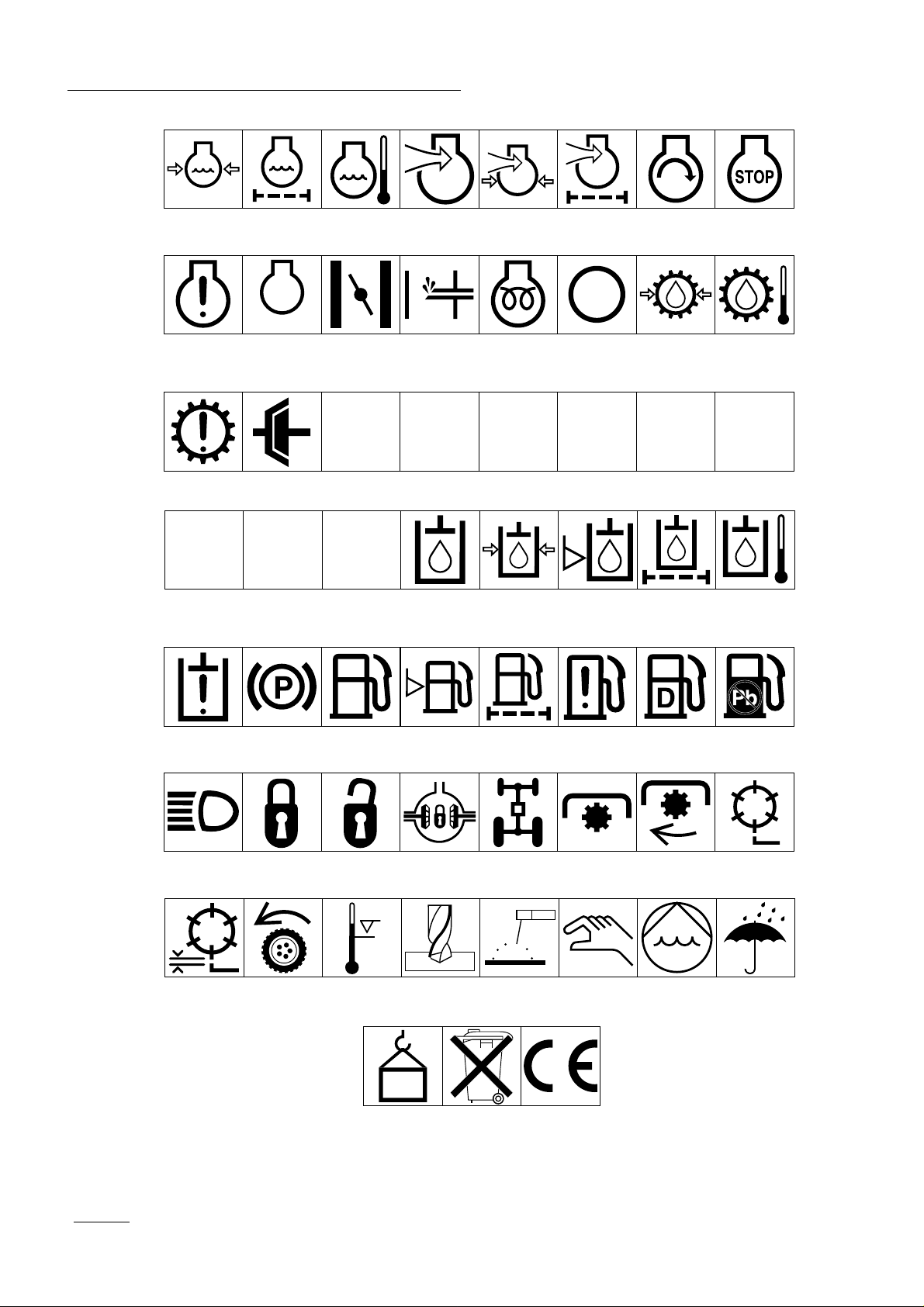
Symbol Glossary
Caustic liquids,
chemical burns to
fingers or hand
Crushing of
whole body,
applied from
above
Cutting or
entanglement of
foot, rotating auger
Poisonous
fumes or toxic
gases, asphyxiation
Crushing of
torso, force
applied from side
Severing of
foot, rotating
knives
Electrical shock,
electrocution
Crushing of fingers
or hand/, force
applied from side
Severing of
fingers or hand,
impeller blade
High pressure
fluid, injection
into body
force applied
from side
Wait until all
machine
components have
completely stopped
before touching them
High pressure
spray, erosion of
flesh
Crushing of
whole body
Severing of
fingers or hand,
engine fan
High pressure
spray, erosion of
flesh
Crushing of
head, torso and
arms
Whole body entanglement,
implement input drive line
Crushing of
fingers
or hand,
force
applied from
above
Cutting of
fingers or hand
Crushing of
toes or foot, force
applied from above
Cutting of footCrushing of leg,
Fingers or
hand entangle-
ment, chain drive
Hand & arm
entanglement,
belt drive
Explosion Fire or open
Shut off engine
& remove key before
performing mainten-
ance or repair work
Thrown or fly-
ing objects, whole
body exposure
flame
Riding on this
machine is allowed
only on a passen-
ger seat & only if the
driver’s view is not
hindered
Thrown or
flying objects,
face exposure
Secure lifting
cylinder with locking
device before getting
in hazardous area
Consult
technical manual
for proper service
procedures
Runover/back-
over, (relevant
machine to appear
in dashed box)
Stay a safe
distance from
the machine
Fasten seat belts Safety alert
Machine tipping,
riding mower
Stay clear of
articulation area
while engine is
running
Machine rollover,
ROPS (relevant
machine to appear
in dashed box)
Stored energy
hazard, kickback
or upward motion
Do not open
or remove safety
shields while
engine is
running
triangle
Do not step on
loading platform if
PTO is connected to tractor
& engine is running
outline safety
alert symbol
Hot surfaces,
burns to fingers
or hands
Do not step
Read operator’s
manual
6
Page 7

Safety
Eye protection
must be worn
Fire, open light
& smoking
prohibited
Level
indicator
Engage Disengage
Head protection
must be worn
Hydraulic
system
Liquid level Filter Temperature Failure/
Hearing
protection must
be worn
Brake system
Attachment
lower
Caution, toxic
risk
First aid
Oil Coolant (water) Intake air Exhaust gas Pressure
Malfunction
Attachment
raise
Spacing distance Snow thrower,
Flush with water Engine Transmission
Start switch/
mechanism
collector auger
On/start Off/stop
Plus/increase/
positive polarity
Minus/decrease/
negative polarity
Horn Battery charging
Machine travel
direction,
forward/rearward
Jack or
support point
condition
Control lever
operating
direction, dual
direction
Draining/
emptying
Hourmeter/elapsed
operating hours
Control lever
operating
direction, multiple
direction
Engine lubricating oil
Fast Slow Continuous
Clockwise
rotation
Engine lubricating
oil pressure
Counter-clockwise rotation
Engine lubricating
oil level
variable, linear
Grease
lubrication
point
Engine lubricating
oil filter
Volume empty Volume full
Oil lubrication
point
Engine
lubricating oil
temperature
Lift point
Engine coolant
7
Page 8
Safety
Engine coolant
pressure
Engine coolant f
ilter
n/min
Engine failure/
malfunction
Transmission
failure/malfunction
Engine rotational
speed/frequency
Clutch Neutral High Low Forward Reverse Park
231
First gear Second gear
Engine
lubricating oil
pressure
Choke Primer (start aid) Electrical preheat
Engine intake/
combustion air
Engine intake/
combustion air
pressure
(low temperature
start aid)
Engine intake/
air filter
Transmission oil Transmission oil
Engine start Engine stop
pressure
Transmission oil
temperature
NHLFRP
Third gear (other #'s
may be used until
the maximum # of forward gears is reached.)
Hydraulic oil Hydraulic oil
Hydraulic oil
pressure
Hydraulic oil level Hydraulic oil filter
temperature
Hydraulic oil
failure/malfunction
Headlights Lock Unlock Differential lock 4-Wheel drive Power Take-Off Power Take-Off,
Reel cutting
element, height
adjustment
Parking brake Fuel Fuel level Fuel filter Fuel system
Traction Above working
temperature range
Drilling Manual metal arc
0430 weight Do not dispose
welding
in the garbage
failure/malfunction
Manual 0356 Water pump
CE logo
Diesel fuel Unleaded fuel
rotational speed
Reel cutting
element
0626 Keep dry
8
Page 9

Specifications
Engine: Perkins, 4-cycle, 3-cylinder, liquid-cooled,
vertical overhead valve, diesel engine with centrifugal
water pump. 13.4 kW governed to a maximum speed
of 3200 rpm. 676 cc displacement. Forced lubrication
gear pump. Mechanical centrifugal governor.
Mechanical fuel transfer pump. Fuel filter/water separator with replaceable filter element. 12-volt (0.7 kW)
starter. Heavy-duty remote mounted air cleaner. Spinon oil
filter.
Radiator: Side-mounted radiator. Cooling system
capacity is 4.7 liters.
Electrical: 12-volt Group 55, 450 cold-cranking amps
at –18°, 75-minute reserve capacity at 27°C. 14-amp
alternator with regulator/rectifier. Seat switch, PTO
and traction interlock switches. Indicator light when
cutting units are running.
Fuel Capacity: 24.6 liters
Traction Drive: Three high-torque hydraulic wheel
motors. 3-wheel drive; two-position selector valve
located below the seat, push for 3-wheel drive and pull
for 2-wheel drive. Oil cooler and shuttle valve provide
positive closed-loop cooling.
Hydraulic Oil Capacity/Filter: Remote mounted, 8.7
liter oil reservoir. 25-micron remote-mounted spin-on
the filter.
Ground Speed: Infinitely variable speed selection in
forward and reverse
Mowing speed: 0–8 km/h
Transport speed: 0–13 km/h
Reverse speed: 0–3 km/h
Tires/Wheels: Two front traction tires, 20 x 10-8,
tubeless, 4-ply rating. Rear steering tire and tube: 20 x
8-8, 2-ply rating. Demountable front rims.
Recommended tire pressure 97–138 kPa front tires and
55–69 kPa rear tire.
teristics of the hydrostat. Parking or emergency brake
is actuated by a ratchet hand lever on the operator’s
left-hand side.
Controls: Foot-operated traction pedal and traction
pedal stop. Hand-operated throttle, ignition switch,
reel engagement switch, cold start button reel unit lift
lever, parking brake and seat adjustment, 2-position
selector valve for 2- or 3-wheel drive selection.
Gauges and Protective Systems: Hour meter, temperature gauge, 4-light warning cluster gauge: oil pressure, water temperature amps and glow plug. High
water temperature shutdown. Electric traction pump
declutching switch for cold start. Engine preheat
incorporated into the ignition switch.
Seat: Adjustable to operator weight, fore and aft, with
removable fold-up armrests.
Cutting Unit Lift: Hydraulic lift with an automatic
reel shut off.
Overall Dimensions:
Wheel tread width: 138
cm
Wheel base: 140
cm
Width: 194
cm
Length: 249
cm
Height: 112
cm
Weight: 562 kg with 5-blade cutting
unit
569 kg with 8-blade cutting
unit
Frame: The frame consists of formed steel, welded
steel and steel tubing components. Tricycle vehicle
with 3-wheel traction drive and rear wheel steering.
Steering: Pinion and sector gear with solid drag link
to rear steer wheel arm.
Brakes: Service braking through the dynamic charac-
9
Page 10

Before Operating
CAUTION
Before servicing or making adjustments to the
machine, stop the engine and remove the key
from the switch.
IMPORTANT Check the oil level every 5 operating
hours or daily. Change the oil after every 50 hours
of operation.
Fill The Fuel T ank
Check The Crankcase Oil
(Fig 1 & 2)
The engine is shipped with oil in the crankcase; however, you must check the oil level before and after you
first start the engine.
1. Position the machine on a level surface.
2. Remove the dipstick and wipe it with a clean
cloth. Push the dipstick down into the dipstick
tube and make sure it is seated fully. Pull out the
dipstick and check the oil level.
3. If the oil level is low, remove the oil fill cap (Fig
2) and gradually add small quantities of oil,
checking the level frequently, until the level
reaches the FULL mark on the dipstick.
4. The engine uses any high-quality 10W30 deter-
gent oil having the American Petroleum
Institute—API—service classification CD.
The engine runs on No. 2 diesel fuel. Fuel tank
capacity is 24.6 liters.
DANGER
Because diesel fuel is flammable, use caution when
storing or handling lt.
• Do not smoke while filling the fuel tank.
• Do not fill the fuel tank while the engine is
running, hot, or when the machine is in an
enclosed area.
• Always fill the fuel tank outside and wipe up
any spilled diesel fuel before starting the
engine.
• Store fuel in a clean, safety-approved container
and keep the cap in place. Use diesel fuel for
the engine only; not for any other purpose.
1. Clean the area around the fuel tank cap.
1. Dipstick
1. Oil fill cap
Figure 1
Figure 2
2. Remove the fuel tank cap.
Figure 3
1. Fuel tank cap
3. Fill the tank to about 2.5 cm below the top of the
tank (bottom of the filler neck). DO NOT
OVERFILL. Then install the cap.
10
Page 11

Before Operating
4. To prevent a fire hazard, wipe up any fuel that
may have spilled.
Check the Cooling System
Clean debris off the radiator screen, radiator and oil
cooler daily (Fig. 4), or hourly if conditions are
extremely dusty and dirt.
The cooling system is filled with a 50/50 solution of
water and permanent ethylene glycol anti-freeze.
Check the level of coolant at the beginning of each
day before you start the engine. Capacity of the cooling system is 5.0 liters.
WARNING
If the engine has been running, pressurized hot
coolant can escape when the radiator cap is
removed and cause burns.
1. Carefully remove the cap from the radiator.
2. Check the level of coolant in the radiator. The
radiator should be filled to the top of the filler
neck.
3. If the coolant level is low, replenish the system.
DO NOT OVERFILL.
4. Install the radiator cap.
Check The Hydraulic System Fluid
The hydraulic system is designed to operate on antiwear hydraulic fluid. The machine’s system is filled at
the factory with approximately 12.5 liters of fluid.
However, check the level of hydraulic fluid before you
first start the engine and daily thereafter.
Group 1—Hydraulic Fluid (Recommended for
ambient temperatures consistently below 37° C.)
1. Radiator screen
2. Radiator
3. Oil cooler
Figure 4
ISO-type 46/68 anti-wear hydraulic fluid
Mobil Mobil Fluid 424
Shell Donax TD
Amoco Amoco 1000
Conoco Power Tran 3
International Harvester Hy-Tran
Texaco TDH
Exxon Torque Fluid
Kendall Hyken 052
BP Oil BP HYD TF
Boron Oil Eldoran UTH
Phillips HG Fluid
Union Oil Hydraulic/Tractor
Fluid
Chevron Tractor Hydraulic
Fluid
Note: All are interchangeable.Group 2—Hydraulic
Fluid (Biodegradable):
ISO VG 32/46 anti-wear hydraulic fluid
1. Radiator cap
Mobil EAL 224 H
IMPORTANT: Due to the nature of biodegradable
fluids, it is critical that the fluid be changed at the
recommended intervals or severe hydraulic component damage may occur.
Figure 5
Note: The fluid in Group 2 is not compatible with the
11
Page 12

Before Operating
fluids in Group 1.
IMPORTANT: These hydraulic fluids are specified
to allow optimal operation of the machine in a wide
range of temperatures. The group 1 fluids are
multi-viscosity hydraulic fluids that allow operation
at lower temperatures without the increased viscosity associated with straight viscosity fluids.
Note: When changing from one type of hydraulic fluid
to the other, be certain you remove all the old fluid
from the system because some brands of one type are
not completely compatible with some brands of the
other type of hydraulic fluid.
IMPORTANT:Use only the types of hydraulic fluids specified. Other fluids could cause system damage.
Note: A red dye additive for the hydraulic system oil
is available in 20 ml bottles. One bottle is sufficient
for 15–23 liters of hydraulic oil. Order Part No. 442500 from your authorized Toro distributor.
1. Position the machine on a level surface.
IMPORTANT To prevent system contamination, clean the top of the hydraulic oil containers before puncturing. Make sure the pour
spout and funnel are clean.
4. Install the reservoir cap. Wipe up any oil that
may have spilled.
Inspect the Fuel Filter
Inspect the fuel filter bowl daily for water or other
contaminants. If water or other contaminants are present, they must be removed before operation.
1. Close the fuel shut-off above the filter.
2. Unscrew the nut securing the bowl to the filter
head. Remove water or other contaminants from
the bowl.
3. Inspect the fuel filter and replace it if it is dirty.
4. Install the bowl to the filter head. Make sure to
position the O-ring correctly between the bowl
mounting nut and the filter head.
2. Make sure the machine has been operated so the
oil is warm. Check the oil level oil by looking in
the sight gauge. If the oil level is at the center of
the gauge, it is sufficient.
3. If the oil level is not at the center of the gauge,
remove the cap from the hydraulic oil reservoir
and slowly fill the reservoir with Mobil 424 or
equivalent hydraulic oil until the level reaches the
center of the sight gauge. DO NOT OVERFILL.
1. Fuel filter
Figure 7
5. Open the fuel shut-off above the filter to re-fill
with fuel. Close the bleed screw.
6. Open the bleed screw on the filter mounting,
allowing the bowl to re-fill with fuel. Close the
bleed screw.
1. Hydraulic reservoir cap
2. Sight Gauge
12
Figure 6
Page 13

DANGER
Because diesel fuel is flammable, use caution
when storing or handling lt.
• Do not smoke while filling the fuel tank.
• Do not fill the fuel tank while the engine
is running, hot, or when the machine is in
an enclosed area.
• Always fill the fuel tank outside and wipe
up any spilled diesel fuel before starting
the engine.
• Store fuel in a clean, safety-approved container and keep the cap in place. Use
diesel fuel for the engine only; not for any
other purpose.
Before Operating
Check Tire Pressure
The tires are over-inflated for shipping. Therefore,
release some of the air to reduce the pressure. Correct
air pressure in the front tires is 83–110 kPa and the
rear tire is 55–68 kPa.
IMPORTANT: Maintain even pressure in all tires
to assure a good quality of cut and proper machine
performance. DO NOT UNDERINFLATE.
Check Reel-to-Bedknife Contact.
Each day before operating, check the reel-to-bedknife
contact, regardless of whether quality of cut had previously been acceptable. There much be light contact
across the full length of the reel and bedknife.
Check The Torque of the Wheel
Nuts
WARNING
Torque the wheel nuts to 61–88 Nm after 1–4
hours of operation and again after 10 hours of
operation and every 200 hours thereafter.
Failure to maintain proper torque could result in
failure or loss of the wheel and may result in
personal injury.
13
Page 14

Contr ols
Traction and Stopping Pedal (Fig. 8, 9, & 10)—The
traction pedal has three functions: one, to make the
machine move forward; two, to move it backward; and
three, to stop it. Using the heel and toe of your right
foot, depress the top of the pedal to move forward and
bottom of the pedal to move backward or to assist in
stopping when moving forward. Also, move the pedal
to the neutral position to stop the machine. For your
comfort, do not rest the heel of your foot on reverse
when operating forward.
Figure 9
Throttle (Figure 11)—Moving the throttle upward
increases engine speed; downward decreases engine
speed.
1. Traction pedal
Figure 8
2. Speed selector
3. Pedal stop
Speed Selector (Fig. 8)—The cam lever at the side of
the traction pedal can be rotated to maintain the
desired speed.
The reverse pedal stop (under the pedal) is set at the
factory to provide 4.8 kmh (3 mph) maximum speed in
reverse.
Ignition Switch—The ignition switch, which is used
to start, stop and preheat the engine, has four positions: OFF, ON, START and GLOW PLUGS (PREHEAT).
To start the engine, turn the key counterclockwise—
GLOW PLUG position—and hold it there for 20 to 30
seconds, then, turn the key clockwise to the START
position to engage the starter motor. Release the key
when the engine starts. The key will move automatically to ON. To shut off the engine, turn the key counterclockwise to OFF. Remove the key from the switch
and install the switch cover to prevent accidental starting.
Cutting Unit Lift Lever (Figures 11)—The lift lever
has three positions: LOWER, RAISE, and NEUTRAL.
To lower the cutting units to the ground, move the lift
lever forward.
When lowering the cutting units, make sure the
hydraulic cylinder is completely retracted before
releasing the lift lever. The cutting units won’t operate
unless the cylinder is retracted.
To raise the cutting units, pull the lift lever rearward to
the RAISE position.
Cutting Unit Drive Switch (Figures 11) —The switch
has two positions: ENGAGE and DISENGAGE. An
amber light on the dash indicates when the reels are
turning. Pull the switch lever out to move from disengage to engage.
Hour Meter (Figures 11)—Indicates the total hours of
machine operation. The hour meter starts whenever
the key switch is turned to “ON.”
Temperature Gauge (Fig. 10)—Registers coolant
temperature in the system.
Oil Pressure Light (Fig. 10)—Glows if the engine oil
pressure drops below a safe level.
WaterTemperature Light (Figure 10)—This light
glows and the engine automatically shuts-down if the
14
Page 15

engine coolant temperature gets too high.
Controls
1. Starter switch & cover
Figure 10
2. Throttle
3. Cutting unit lift lever
4. Cutting unit drive switch
S. Hour meter
6. Water temperature gauge
7. Oil pressure light
8. Amp gauge
9. Glow plug indicator
10. High water temperature shut-down light
11. Reel operating light
12. Cold-start button
1. Deck engagement control Pull out—Two-wheel drive
Figure 11
Push in—Three-wheel drive
Reel Speed Control (Fig. 12)—For the desired reel
speed, turn the reel speed control knob to the appropriate setting for height-of-cut setting and mower
speed. Refer to Selecting the Clip Rate section of this
manual.
Backlap Control (Fig. 12)—Turn the knob clockwise
0for backlapping and counterclockwise for mowing
Amp Light (Fig. 10)—The amp light should be off
when the engine is running. If it is on, the charging
system should be checked and repaired as necessary.
Glow Plug Indicator (Fig. 10)—This indicator light
will glow when the glow plugs are operating.
Cold Start Button (Fig. 10)—When starting a cold
engine, press the cold start button to electrically declutch the traction pump. When the engine starts,
release the button.
Parking Brake— Whenever the engine is shut off,
the parking brake must be engaged to prevent accidental movement of the machine. To engage the parking
brake, pull back on the lever.
Drive Engagement Control (Fig 11)—Located on the
lower left side of the operator. Pull the knob out for
2-wheel drive; push the knob in for 3-wheel drive.
1. Reel speed control
Fig. 12
2. Backlap control
Seat Adjustments (Fig. 13)
Fore and Aft Adjustment—Move the lever on the side
of the seat outward, slide the seat to the desired position and release the lever to lock the seat into position.
Deluxe Seat Adjustments (Fig. 13)
Weight Adjustment—Push the lever up or down to
adjust to the operator’s weight. Lever up—light operator, lever in middle position—medium weight operator or lever down for heavy operator.
Inclining Backrest—Turn the handle to adjust the
backrest angle. (Deluxe Seat only).
15
Page 16

Controls
1. Fore and aft lever
Figure 13
2. Weight adjustment lever
3. Inclining backrest
Fuel Shut-off Valves, (Fig. 14 & 15)—Close the fuel
shutoff valves under the fuel tank and on the fuel filter
when storing the machine.
1. Fuel shut off (on the fuel filter)
Figure 15
1. Fuel shut off (under the fuel tank)
Figure 14
16
Page 17

Operating Instructions
Starting/Stopping The Engine
IMPORTANT: The fuel system may have to be
bled if any of the following situations have
occurred:
• Initial start up of a new engine.
• The engine has ceased running due to lack of
fuel.
• Maintenance has been done on fuel system
components; i.e., the filter replaced, etc.
Refer to Bleeding The fuel System
1. Be sure the parking brake is set and the reel drive
switch is in DISENGAGE.
2. Remove your foot from the traction pedal and
make sure the pedal is in the neutral position.
3. Move the throttle lever to the full throttle position.
be sure all parts operate correctly.
Turn the steering wheel to the left and right to
check steering response. Then shut the engine off
and check for oil leaks, loose parts and any other
noticeable malfunctions.
CAUTION
Shut off the engine and wit for all moving
parts to stop before checking for oil leaks,
loose parts and other malfunctions.
7. To stop the engine, move the throttle control
downward to IDLE, move the reel drive switch to
DISENGAGE and turn the ignition key to OFF.
Remove the key from the switch and install the
switch cover to prevent accidental starting.
8. Close the fuel shut-off valves before storing the
machine.
Bleeding The Fuel System
4. Remove the cover from the ignition switch.
Insert the key and turn it counterclockwise to the
GLOW PLUG position—and hold it there for
approximately 20 to 30 seconds. Then, turn the
key clockwise to START to engage the starter
motor. Release the key when the engine starts.
The key will move automatically to ON.
IMPORTANT To prevent overheating the
starter motor, do not engage the starter longer
than 10 seconds. After 10 seconds of continuous cranking, wait 60 seconds before engaging
the starter motor again.
5. For cold-weather starting, press the cold-start but-
ton to declutch the electric traction pump. When
the engine starts, release the button.
6. When starting the engine for the first time, or
after an engine overhaul, operate the machine in
forward and reverse for one to two minutes. Also
operate the lift lever and the reel drive switch to
1. Park the machine on a level surface. Make sure
the fuel tank is at least half full.
DANGER
Because diesel fuel is flammable, use caution
when storing or handling lt.
• Do not smoke while filling the fuel tank.
• Do not fill the fuel tank while the engine
is running, hot, or when the machine is in
an enclosed area.
• Always fill the fuel tank outside and wipe
up any spilled diesel fuel before starting
the engine.
• Store fuel in a clean, safety-approved container and keep the cap in place. Use
diesel fuel for the engine only; not for any
other purpose.
2. Unlatch and raise the hood.
17
Page 18

Operating
3. Open the fuel shut-off valve under the fuel tank
and on the fuel filter.
4. Open the (2) bleed screws on the side of the fuel
filter mounting head, allowing the bowl to re-fill
with fuel. Close bleed screws when the bowl is
filled.
1. Fuel shutoff
Figure 16
2. Bleed screws (2)
3. Bowl
5. On the left side of the engine (below the alterna-
tor) find the transfer pump inlet screw. Note the
angle of the fitting on the transfer pump inlet and
loosen the screw (left screw only).
6. When a steady stream of fuel flows out of the
transfer pump screw, tighten the screw, retaining
the angle of fitting before it was loosened.
7. Loosen the injection pump inlet screw on the
right side of the engine.
8. Pump the priming lever until a steady stream of
fuel flows out of the injection pump inlet screw,
then tighten the screw.
1. Transfer pump screw
Figure 17
2. Injection pump Inlet screw location
3. Injection pump inlet screw
4. Priming lever
5. Note fitting angle
Check The Interlock Switch
Operation
CAUTION
Do not disconnect the safety switches because they
are for the operator’s protection. Check the safety
switch operation dally to be sure the system operates
correctly. If a switch is not operating correctly,
replace it before operating the machine. Replace the
switches every two years to be sure of maximum
safety.
1. Be sure the parking brake is set and all bystanders
are away from the area of operation. Keep your
hands and feet away from the cutting units.
18
2. With the operator off the seat, the backlap knob
turned counterclockwise, the traction pedal in
neutral and the reel switch switch in the OFF
position, the engine should start. If either the
traction pedal is depressed or the reel switch is
turned ON with the operator off the seat, the
engine should stop. Correct the problem if the
safety switches are not operating correctly.
3. With the engine running, the operator off the seat
and the backlap knob turned clockwise, the
engine should not stop when the reel switch is
turned ON. Correct the problem if the safety
Page 19

Operating
switches are not operating correctly.
4. With the operator on the seat, the engine running,
and the reel switch in the ON position, the dash
indicator light should be glowing and the reel
motors turning when the lift cylinder is fully
retracted. As the lift cylinder is extended, the
light should go out and the reel motors should
stop turning. Correct the problem if the system is
not operating correctly.
5. With the operator on the sea, the engine must not
start with either reel switch engaged or the traction control engaged. Correct the problem if the
system is not operating correctly.
Towing the Traction Unit
In case of emergency, the Reelmaster 2300-D can be
towed for a short distance. However, Toro does not
recommend this as a standard procedure.
IMPORTANT Do not tow the machine faster than
3–4.8 kmh because the drive system may be damaged. If the machine must be moved a considerable distance, transport it on a truck or trailer.
nance machines. Points to consider when operating
are the traction drive, engine speed and the load on the
cutting units. Regulate the traction pedal to keep the
engine rpm high and somewhat constant while mowing to maintain adequate power for the traction and
cutting units. Adjust the speed selector to maintain
constant ground speed and quality of cut. However,
when on hilly terrain, do not use the speed selector.
Follow the operating guidelines in this manual and
know how to operate the machine safely on all types
of terrain. Never traverse or mow up and down on
slopes over 20 degrees, nor traverse or mow side hills
in excess of 15 degrees. Always plan well ahead to
avoid the need for sudden stops, starts or turns. To
stop, use the reverse pedal for braking. Before stopping the engine, disengage all controls, move the
throttle to IDLE, and set the parking brake.
Selecting Clip Rate (Reel Speed)
To achieve a consistent, high-quality cut and a uniform after-cut appearance, the reel speed must be
matched to the height of cut.
1. Turn the by-pass valve on pump 90°.
Figure 18
1. Hose plug
2. Before starting the engine, close the by-pass
valve securely by rotating it 90°. Do not start the
engine when the valve is open.
Operating Characteristics
Practice operating the Reelmaster and become thoroughly familiar with it. Because of its hydrostatic
transmission and choices of either two or three wheel
drive, its characteristics differ from many turf mainte-
1. Reel speed control
Figure 19
Adjust the clip rate (reel speed) as follows:
1. Verify the height-of-cut setting on the cutting
units. Using the column of the chart listing either
5- or 8-blade reels, find the height-of-cut listing
nearest the actual height-of-cut setting. Look
across the chart to find the number corresponding
to that height of cut.
2. Turn the reel speed control knob to the number
setting you found in step 1.
3. Operate the machine for several days, then exam-
19
Page 20

Operating
ine the cut to ensure you are satisfied with the quality of cut. The reel speed knob may be set one
position of either side of the position on the chart to
account for differences in grass condition, grass
length removed, and your personal preferences.
Training Period
Before mowing with the Reelmaster, The Toro Company
suggests you find a clear area and practice starting and
stopping, raising and lowering the cutting units, turning,
etc. This training period will help the operator gain confidence in the performance of the Reelmaster.
Before Mowing
Inspect the area for debris and clear it if necessary.
Determine the direction best to mow on the previous
mowing direction. Always mow in an alternate pattern
from the previous mowing, so that the grass blades will
be less apt to lay down and therefore be difficult to gather between the reel blades and bedknife.
Transport Operation
Be sure the cutting units are in the fully up position,
move the traction pedal stop from under the pedal to
allow full traction pedal travel and place the throttle
control FAST. While operating on slopes and uneven
terrain, always reduce speed and use extreme caution
before turning to reduce risk of tipping or losing control.
Watch carefully for, and avoid, holes in the terrain, sudden drop-off s and other hidden hazards. To prevent
costly damage and downtime, familiarize yourself with
the width of the Reelmaster. Do not attempt to pass
between immovable objects placed close together.
Inspection And Clean-Up After
Mowing
After mowing, thoroughly wash the machine with a garden hose—without a nozzle so excessive water pressure
will not cause contamination and damage to seals and
bearings.
Height of Cut (cm)
6.4
6.0
5.7
5.4
5.1
4.8
4.5
4.1
3.8
3.5
3.2
2.9
2.5
2.2
1.9
1.6
1.3
1.0
5-Blade Reel
Reel Speeds Reel Speeds
3-Wheel Drive
5–8 kmh
3
3
4
4
4
4
5
5
6
6
7
7
8
9
Selecting Reel Speed
2-Wheel Drive
10–11 kmh
5
5
5
5
6
6
7
7
8-Blade Reel
3-Wheel Drive
5–8 kmh
3
3
3
4
4
4
5
5
6
7
9
9
9
2-Wheel Drive
10–11 kmh
3
3
3
3
3
4
4
4
5
5
6
7
9
20
Page 21

Make sure the radiator screen, radiator and the oil
cooler(diesel models) and cooling fins and area around
the engine cooling air intake (gasoline models) are
kept free of dirt or grass clippings. After cleaning, it
is recommended
– the machine be inspected for possible hydraulic
fluid leaks, damage or wear to the hydraulic and
mechanical components
– the cutting units be checked for sharpness and cor-
rect reel-to-bedknife adjustment.
Operating
21
Page 22

Maintenance
Minimum Recommended Maintenance Intervals
Inspect the air filter, dust
cap and burp valve
Lube all grease fittings
✝Change engine oil
✝Check engine belt tension
✝Change the engine oil filter
✝Check the traction belt’s tension
Service the air filter
Replace the fuel filter
✝Replace the hydraulic filter
✝Torque the wheel lug nuts
Replace hydraulic fluid
Check battery level and connections
Inspect the traction linkage movement
✝✝Torque the head bolts and adjust the valves
✝✝Check the engine RPM (idle and full throttle)
✝Initial break in at 10 hours
✝✝Initial break in at 50 hours
Every 50
hours
Every 100
hours
Every
200 hours
Every
400 hours
Replace moving hoses
Replace safety switches
Flush cooling the cooling system and replace hoses
Replace the thermostat
Drain and flush the fuel tank
Drain and flush the hydraulic tank
Annual Recommendations:
Items are recommended every 1000 hours or
two years, whichever occurs first.
22
Page 23

Quick Reference Aid
1. Engine oil level
2. Engine oil drain (17mm socket)
3. Hydraulic oil level—Center of sight glass
4. Belts (Fan/water pump, hydraulic pump)
5. Coolant level fill
6. Fuel—Diesel only
7. Grease points
8. Radiator screen
9. Air cleaner
10. Water separator/fuel filter
11. Battery
12. Tire pressure:
(.8–1.1 bar) front
(.6–.7 bar) rear
13. Fuses
GREASING BEARINGS AND BUSHINGS
(Fig. 20–26)
The traction unit and cutting unit’s grease fittings must
be lubricated regularly with No. 2 General Purpose
Lithium Base Grease. If the machine is operated under
normal conditions, lubricate bearings and bushings after
every 50 hours of operation. Bearings and bushings
must be lubricated daily when operating conditions are
extremely dusty and dirty. Dusty and dirty operating
conditions could cause dirt to get into the bearings and
bushings, resulting in accelerated wear.
Engine oil
Hyd. circuit oil
Fuel filter
Air cleaner
Fuel
Coolant
Fluid
Type
SAE
10W30 CD
Mobil 424 12.5 l 400 hours 200 hours 54-0110
No. 2
Diesel
50/50
Ethylene gly-
col water
Capacity
3.0 l 50 hours 100 hours 85-4930
Clean every 50 hours 200 hours 93-2195
24.5 l
4.7 l
Change
Fluid
Change
Filter
200 hours
Drain and flush, 2 years
Filter
Part No.
Perkins
130366040
The traction unit bearings and bushings that must be
lubricated are:
Steering column (Fig. 20), steering gears (2) (Under
skirt below steering sector), steering shaft (2) (Fig. 21),
lift arms (3) (Fig. 22), rear lift cylinder pivot (Fig.24),
traction pedal pivot (Fig 25).
Also, apply grease to slots in cylinder support (Fig. 26).
Figure 20
23
Page 24

Maintenance
Figure 21
Figure 24
Figure 22
Figure 23
Figure 25
Figure 26
24
Page 25

CAUTION
Before servicing or making adjustments to the
machine, stop the engine and remove the key
from the switch.
Hood Removal
The hood may be easily removed to ease maintenance
in the engine area.
1. Unlatch and raise the hood.
2. Remove the cotter pin securing the hood pivot to
the mounting brackets.
3. Slide the hood to the right side, lift the other side
and pull the hood out of the brackets.
Maintenance
Figure 28
1. Dust Cup & Baffle
2. Filter Element
3. Air Cleaner Body
4. Reverse the procedure to install the hood.
Figure 27
1. Cotter pin
Servicing The Air Cleaner
Service the air cleaner filter every 400 hours, or more
frequently in extremely dusty or dirty conditions, by
washing or using compressed air.
1. Release the latches that secure the air cleaner
cover to the air cleaner body. Separate the cover
from the body. Clean inside the air cleaner cover.
2. Gently slide the filter out of the air cleaner body
to reduce the amount of dust dislodged. Avoid
knocking the filter against the air cleaner’s body.
3. Inspect the filter and discard it if it is damaged.
Do not was or reuse a damaged filter.
Washing Method
1. Prepare a solution of filter cleaner and water and
soak the filter element about 15 minutes.
2. After soaking the filter for 15 minutes, rinse it
with clear water.
3. Dry the filter element using warm, flowing air no
hotter than 71° C, or allow the element to air dry.
Do not use compressed air or a light bulb to dry
the filter element because they may damage it.
Compressed Air Method
1. Blow compressed air from inside to the the out-
side of the dry filter element. Do not exceed 689
kPa (100 psi) to prevent damage to the filter.
2. Keep the air hose nozzle at least 3 cm from the
pleated paper, and move the nozzle up and down
while rotating the filter element.
3. Inspect for holes and tears by looking through the
filter toward a bright light.
25
Page 26

Maintenance
Installing A New Air Filter
1. Inspect the new filter for shipping damage.
Check the sealing end of the filter. Do not install
a damaged filter.
2. Insert the new filter into the air cleaner body.
Make sure the filter is sealed properly by applying pressure to the outer rim of the filter when
installing. Do not press on the flexible center of
the filter.
3. Install the cover and secure the latches. Make
sure the cover is positioned with the TOP side up.
Changing The Engine Oil And
Filter
Change the oil and the oil filter initially after the first
20 hours of operation, thereafter change the oil every
50 hours and the oil filter every 100 hours.
1. Reservoir plug
Figure 29
2. Reservoir outlet
This will retain most of the fluid in the reservoir
when the filter is removed.
3. Clean the area around the hydraulic oil filter.
Remove the filter from the bottom of the filter
housing and allow the oil to flow into a drain pan.
Use a bottom type filter wrench.
1. Locate the engine the oil drain plug on the bottom
of the oil pan.. Remove the drain plug and let the
oil flow into the drain pan. When the oil stops,
install the drain plug.
2. Locate the engine filter on the front of the engine.
Remove the oil filter. Apply a light coat of clean
oil to the new filter seal before screwing it on.
DO NOT OVER-TIGHTEN.
3. Add oil to the crankcase.
Changing the Hydraulic System
Fluid And Filter
The hydraulic system filter must be changed after the
first five hours of operation, and after that, every 250
hours of operation or yearly, whichever comes first.
Use a genuine Toro oil filter for replacement. The
hydraulic fluid must be changed every 500 hours of
operation or yearly, whichever comes first.
1. Park the machine on a level surface, lower the
cutting units, set the parking brake and turn the
engine off.
2. If only the filter is to be changed, remove the
reservoir cap and insert the reservoir plug (Fig.
30), to the block outlet.
1. Hydraulic oil filter
Figure 30
4. Apply a film of oil on the filter gasket. Install the
filter by hand until gasket contacts mounting
head; then tighten the filter an additional threefourths of a turn.
5. Fill the reservoir to the correct level.
6. Place all controls in the neutral or disengaged
position and start the engine. Run the engine at
the lowest possible rpm to purge the system of
air.
7. Run the engine until the lift cylinder extends and
retracts and forward and reverse wheel motion is
achieved.
8. Stop the engine and check the oil level in the
26
Page 27

Maintenance
reservoir; add oil if necessary.
9. Check all connections for leaks.
Backlapping
DANGER
TO AVOID PERSONAL INJURY OR DEATH:
• Never place your hands or feet in the reel area
while the engine is running.
• While backlapping, reels may stall and then
restart.
• Do not attempt to restart reels by hand or foot.
• Do not adjust reels while the engine is running.
• If the reel stalls, stop the engine before trying
to clear the reel.
1. Position the machine on a clean, level surface,
lower the cutting units, stop the engine, engage
parking brake and remove key from ignition
switch.
panel
6. Apply lapping compound with long handled
brush supplied with machine.
CAUTION
Be careful when lapping the reel because contact with the reel or other moving parts can
result in personal injury.
7. To make an adjustment to the cutting units while
backlapping, turn reels OFF by pushing in on
knob on instrument panel and turning engine
OFF. After adjustments have been completed,
repeat steps 4-6.
8. When backlap operation is completed, rotate
backlap knob clockwise to MOW position, set
reel speed controls to desired mowing setting and
wash ail lapping compound off cutting units.
NOTE: Additional instructions and procedures
on Backlapping are available in the TORO
Sharpening Reel & Rotary Mowers Manual Form
No. 80-300PT.
2. Unlatch and raise the hood to expose controls.
3. Turn backlap knob, on valve block, clockwise to
backlap position. Turn the reel speed knob to
position 1.
Figure 31
1. Reel speed knob
2. Backlap knob
4. Make initial reel to bedknife adjustments appro-
priate for backlapping on all cutting units Start
engine and set engine to low idle speed.
NOTE: For a better cutting edge, run a file
across the front face of the bedknife when the
lapping operation is completed. This will remove
any burrs or rough edges that may have built up
on the cutting edge.
MODEL AND SERIAL NUMBER
The mower has two identification numbers: a model
number and a serial number. The two numbers are
stamped into a plate that is riveted to the frame at the
rear of the mower. In any correspondence concerning
the mower, supply the model and serial numbers to
assure that correct information and replacement parts
are obtained.
NOTE: Do not order by reference number if a parts
catalog is being used; use the part number.
To order replacement parts from an Authorized TORO
Service Dealer, supply the following information:
1. Model and serial numbers of the mower.
5. Engage reels by pulling out knob on instrument
2. Part number, description and quantity of part(s)
desired.
27
Page 28

15° and 20° Slope Chart
Align this edge with a vertical surface such as a tree, building, pole, etc.
Example: Compare
the slop with the
folded edge.
This is a 15° Slope
This is a 20°Slope
Fold along the appropriate line
28
Page 29

 Loading...