

Page 1
FORM NO. 3318-231 GB Rev A
®
MODEL NO. 03410TE—70001 & UP
REELMASTER® 216
OPERATOR’S
MANUAL
© The T oro Company—1996
Page 2

This operator's manual has instructions on safety, operation, and maintenance.
This manual emphasizes safety, mechanical and general product information. DANGER, WARNING and CAUTION
identify safety messages. Whenever the triangular safety alert symbol appears, understand the safety message that
follows. “IMPORTANT” highlights special mechanical information and “NOTE” emphasizes general product information worthy of special attention.
IDENTIFICATION AND ORDERING
MODEL AND SERIAL NUMBER
The model and serial number for the traction unit is on a plate that is mounted on the left front frame member. The
model and serial number for the cutting unit is on a plate that is mounted on the top front of the center cutting unit.
Use model and serial number in all correspondence and when ordering parts.
To order replacement parts from an authorized TORO Distributor, supply the following information:
1. Model and serial numbers of the machine.
2. Part number, description and quantity of parts desired.
NOTE: Do not order by reference number if a parts catalog is being used; use the part number.
Table of Contents
Safety 3
Specifications 9
Before Operating 10
Controls 13
First-Time Operation 16
Operating 20
Maintenance 23
Page
2
Page 3

Safety
Training
1. Read the instructions carefully. Be familiar with
the controls and the proper use of the equipment.
2. Never allow children or people unfamiliar with
these instructions to use the lawn mower. Local
regulations may restrict the age of the operator.
3. Never mow while people, especially children, or
pets are nearby.
4. Keep in mind that the operator or user is responsi-
ble for accidents or hazards occurring to other
people or their property.
5. Do not carry passengers.
6. All drivers should seek and obtain professional
and practical instruction. Such instruction should
emphasize:
• the need for care and concentration when
working with ride-on machines;
is to be used and remove all objects which may
be thrown by the machine.
3. WARNING—Petrol is highly flammable.
• Store fuel in containers specifically designed
for this purpose.
• Refuel outdoors only and do not smoke
while refueling.
• Add fuel before starting the engine. Never
remove the cap of the fuel tank or add petrol
while the engine is running or when the
engine is hot.
• If petrol is spilled, do not attempt to start the
engine but move the machine away from the
are of spillage and avoid creating any source
of ignition until petrol vapors have dissipated.
• Replace all fuel tanks and container caps
securely.
4. Replace faulty silencers.
• control of a ride-on machine sliding on a
slope will not be regained by the application
of the brake. The main reasons for loss of
control are:
– insufficient wheel grip;
– being driven too fast;
– inadequate braking;
– the type of machine is unsuitable for its
task;
– lack of awareness of the effects of
ground conditions, especially slopes;
– incorrect hitching and load distribution.
Preparation
1. While mowing, always wear substantial footwear
and long trousers. Do not operate the equipment
when barefoot or wearing open sandals.
2. Thoroughly inspect the area where the equipment
Operation
1. Do not operate the engine in a confined space
where dangerous carbon monoxide fumes can collect.
2. Mow only in daylight or in good artificial light.
3. Before attempting to start the engine, disengage
all blade attachment clutches and shift into neutral.
4. Do not use on slopes of more than:
• Never mow side hills over 5°
• Never mow uphill over 10°
• Never mow downhill over 15°
5. Remember there is no such thing as a “safe”
slope. Travel on grass slopes requires particular
care. To guard against overturning:
3
Page 4

Safety
• do not stop or start suddenly when going up
or downhill;
• engage the clutch slowly, and always keep
the machine in gear, especially when travailing downhill;
• machine speeds should be kept low on
slopes and during tight turns;
• stay alert for bumps and hollows and other
hidden hazards;
• never mow across the face of the slope,
unless the lawn mower is designed for this
purpose.
6. Use care when pulling loads or using heavy
equipment.
• Use only approved drawbar hitch points.
• Limit loads to those you can safely control.
• Do not turn sharply. Use care when reversing.
• Use counterweight(s) or wheel weights
when suggested in the instruction handbook.
• change into neutral and set the parking
brake;
• stop the engine and remove the key.
13. Disengage the drive to attachments when trans-
porting or not in use.
14. Stop the engine and disengage the drive to the
attachment
• before refueling;
• before removing the grass catcher;
• before making height adjustments unless the
adjustment can be made from the operator’s
position.
• before clearing blockages;
• before checking, cleaning or working on the
lawnmower;
• after striking a foreign object. Inspect the
lawnmower for damage and make repairs
before restarting and operating the equipment.
7. Watch out for traffic when crossing or near road-
ways.
8. Stop the blades rotating before crossing surfaces
other than grass.
9. When using any attachments, never direct dis-
charge of material toward bystanders nor allow
anyone near the machine while in operation .
10. Never operate the lawn mower with defective
guards, shields or without safety protective
devices in place.
11. Do not change the engine governor settings or
overspeed the engine. Operating the engine at
excessive speeds may increase the hazard of personal injury.
12. Before leaving the operator’s position:
• disengage the power take-off and lower the
attachments;
15. Reduce the throttle setting during engine runout
and, if the engine is provided with a shutoff
valve, turn the fuel off at the conclusion of mowing.
Maintenance and Storage
1. Keep all nuts, bolts and screws tight to be sure
the equipment is in safe working condition.
2. Never store the equipment with petrol in the tank
inside a building where fumes may reach an open
flame or spark.
3. Allow the engine to cool before storing in any
enclosure.
4. To reduce the fire hazard, keep the engine,
silencer, battery compartment and petrol storage
area free of grass, leaves, or excessive grease.
5. Check the grass catcher frequently for wear or
deterioration.
4
Page 5

Safety
6. Replace worn or damaged parts for safety.
7. If the fuel tank has to be drained, this should be
done outdoors.
8. Be careful during adjustment of the machine to pre-
vent entrapment of the fingers between moving
blades and fixed parts of the machine.
9. On multi-bladed machines, take care as rotating
one blade can cause other blades to rotate.
10. When the machine is to be parked, stored or left
unattended, lower the cutting means unless a positive mechanical lock is used.
Sound & Vibration Levels
Sound Levels
This unit has an equivalent continuous A-weighted
sound pressure at the operator ear of: 90 dB(A), based
on measurements of identical machines per SAE
J1174—Mar 85 procedures.
This unit has a sound power level of 105 dB(A)/1pW,
based on measurements of identical machines per procedures outlined in Directive 79/113/EEC and amendments
Vibration Levels
This unit has a vibration level of 7.5 m/s2at the posterior, based on measurements of identical machines per
ISO 2631 procedures.
2
This unit does not exceed a vibration level of 0.9 m/s
the posterior based on measurements of identical
machines per ISO 2631 procedures.
at
5
Page 6

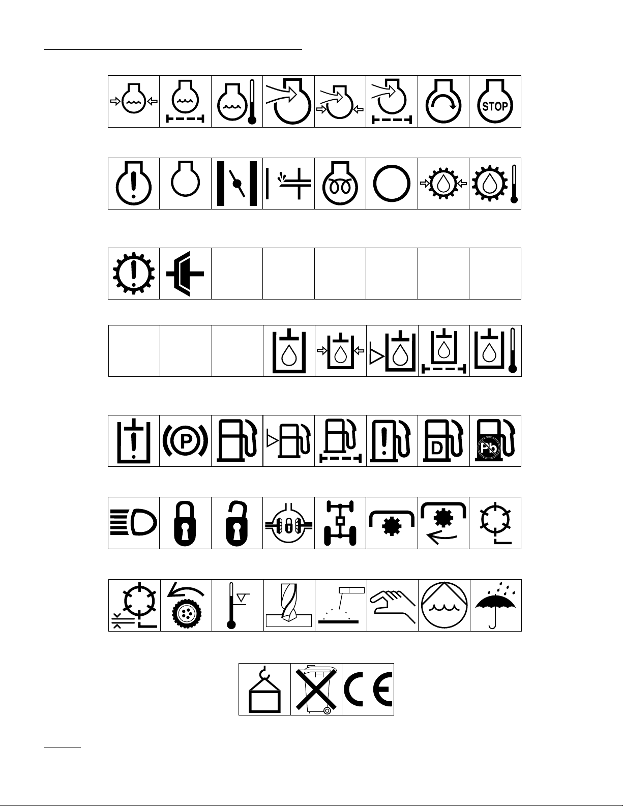
Symbol Glossary
Caustic liquids,
chemical burns to
fingers or hand
Crushing of
whole body,
applied from
above
Cutting or
entanglement of
foot, rotating auger
Poisonous
fumes or toxic
gases, asphyxiation
Crushing of
torso, force
applied from side
Severing of
foot, rotating
knives
Electrical shock,
electrocution
Crushing of fingers
or hand/, force
applied from side
Severing of
fingers or hand,
impeller blade
High pressure
fluid, injection
into body
force applied
from side
Wait until all
machine
components have
completely stopped
before touching them
High pressure
spray, erosion of
flesh
Crushing of
whole body
Severing of
fingers or hand,
engine fan
High pressure
spray, erosion of
flesh
Crushing of
head, torso and
arms
Whole body entanglement,
implement input drive line
Crushing of
fingers
or hand,
force
applied from
above
Cutting of
fingers or hand
Crushing of
toes or foot, force
applied from above
Cutting of footCrushing of leg,
Fingers or
hand entangle-
ment, chain drive
Hand & arm
entanglement,
belt drive
Explosion Fire or open
Shut off engine
& remove key before
performing mainten-
ance or repair work
Thrown or fly-
ing objects, whole
body exposure
flame
Riding on this
machine is allowed
only on a passen-
ger seat & only if the
driver’s view is not
hindered
Thrown or
flying objects,
face exposure
Secure lifting
cylinder with locking
device before getting
in hazardous area
Consult
technical manual
for proper service
procedures
Runover/back-
over, (relevant
machine to appear
in dashed box)
Stay a safe
distance from
the machine
Fasten seat belts Safety alert
Machine tipping,
riding mower
Stay clear of
articulation area
while engine is
running
Machine rollover,
ROPS (relevant
machine to appear
in dashed box)
Stored energy
hazard, kickback
or upward motion
Do not open
or remove safety
shields while
engine is
running
triangle
Do not step on
loading platform if
PTO is connected to tractor
& engine is running
outline safety
alert symbol
Hot surfaces,
burns to fingers
or hands
Do not step
Read operator’s
manual
6
Page 7

Safety
Eye protection
must be worn
Fire, open light
& smoking
prohibited
Level
indicator
Head protection
must be worn
Hydraulic
system
Liquid level Filter Temperature Failure/
Hearing
protection must
be worn
Brake system
Caution, toxic
risk
Oil Coolant (water) Intake air Exhaust gas Pressure
First aid
Malfunction
Flush with water Engine Transmission
Start switch/
mechanism
On/start Off/stop
Engage Disengage
Horn Battery charging
Machine travel
direction,
forward/rearward
Jack or
support point
condition
Control lever
operating
direction, dual
direction
Draining/
emptying
Attachment
lower
Hourmeter/elapsed
operating hours
Control lever
operating
direction, multiple
direction
Engine lubricating oil
Attachment
raise
Fast Slow Continuous
Clockwise
rotation
Engine lubricating
oil pressure
Spacing distance Snow thrower,
Counter-clockwise rotation
Engine lubricating
oil level
collector auger
variable, linear
Grease
lubrication
point
Engine lubricating
oil filter
Plus/increase/
positive polarity
Volume empty Volume full
Oil lubrication
point
Engine
lubricating oil
temperature
Minus/decrease/
negative polarity
Lift point
Engine coolant
7
Page 8
Safety
Engine coolant
pressure
Engine coolant f
ilter
n/min
Engine failure/
malfunction
Transmission
failure/malfunction
Engine rotational
speed/frequency
Clutch Neutral High Low Forward Reverse Park
231
First gear Second gear
Engine
lubricating oil
pressure
Choke Primer (start aid) Electrical preheat
Engine intake/
combustion air
Engine intake/
combustion air
pressure
(low temperature
start aid)
Engine intake/
air filter
Transmission oil Transmission oil
Engine start Engine stop
pressure
Transmission oil
temperature
NHLFRP
Third gear (other #'s
may be used until
the maximum # of forward gears is reached.)
Hydraulic oil Hydraulic oil
Hydraulic oil
pressure
Hydraulic oil level Hydraulic oil filter
temperature
Hydraulic oil
failure/malfunction
Headlights Lock Unlock Differential lock 4-Wheel drive Power Take-Off Power Take-Off,
Reel cutting
element, height
adjustment
Parking brake Fuel Fuel level Fuel filter Fuel system
Traction Above working
temperature range
Drilling Manual metal arc
0430 weight Do not dispose
welding
in the garbage
failure/malfunction
Manual 0356 Water pump
CE logo
Diesel fuel Unleaded fuel
rotational speed
Reel cutting
element
0626 Keep dry
8
Page 9

Specifications
Diesel Model
216 Diesel Engine: Perkins, 4-cycle, 3-cylinder, liquid
cooled, vertical overhead valve, diesel engine with centrifugal water pump. 16.5 hp governed to a maximum
speed of 3200 rpm. 37.60 cu. in. displacement. Forced
lubrication gear pump. Mechanical fuel transfer pump.
Fuel filter/water separator with replaceable filter element. Heavy-duty remote mounted air cleaner.
Radiator: Side mounted radiator, industrial construc-
1
tion. Cooling system capacity is 5 liters (5-
Electrical: 12-volt starter. Interlock switches. 14-amp
alternator with remote electronic regulator rectifier.
Fuel Capacity: 24.6 liters (6.5 gallons.)
Hydraulic Oil Capacity/Filter: 8.7 liter (2.3 gallon) oil
reservoir. 12.5 liter (3.3 gallon) total system capacity.
10-micron remote mounted spin on the filter.
Ground Speed: Infinitely variable speed selection in
forward and reverse
Mowing speed: 0–8 km/h (0–5 mph)
Transport speed: 0–12.9/kmh (0–8 mph)
Reverse speed: 0–3 km/h (0–4.8 mph)
⁄4 quarts).
Gasoline Model
Reverse speed: 0–4.8 km/h (0–3 mph)
Both Models
Traction Drive: Hydrostatic drive; variable displacement pump, infinitely variable in both forward and
reverse direction. High-torque hydraulic wheel motors.
Brakes: Service braking through the dynamic characteristics of the hydrostat. Parking or emergency brake is
actuated by a ratchet hand lever.
Tires/Wheels: Two front traction tires, 18 x 8.50-8,
tubeless, 4-ply rating. Rear steering tire 18 x 6.50-8, 4ply tire with tube. Recommended tire pressure 97–138
kPa (12–16 psi).
Frame: The frame consists of formed steel, welded steel
and steel tubing components.
Model 03420: Tricycle vehicle with 2-wheel traction
drive in front and rear wheel steering.
Model 03425: Tricycle vehicle with 3-wheel traction
drive and rear wheel steering.
Model 03410: Tricycle vehicle with 2-wheel traction
drive in front and rear wheel steering.
Model 03430: Tricycle vehicle with 3-wheel traction
drive and rear wheel steering.
216 Gasoline Engine: Kohler, 4-cycle, air cooled, 11.9
kW (16 hp) @ 3,600 rpm, 588 cc (35.9 cu. in.) displacement. Mechanical fuel pump, large capacity dual element air cleaner, 2.5 l (5-1/4 pint) oil capacity
Steering: Adjustable steering wheel. Pinion gear and
sector gear with solid drag link to the rear steer wheel
arm.
Fuel Capacity: 22.7 liters (6.0 gallons.)
Electrical: 12-volt starter. Interlock switches. 15-amp
alternator with remote electronic regulator rectifier.
Ground Speed: Infinitely variable speed selection in
forward and reverse
Mowing speed: 0–8 km/h (0–5 mph)
Transport speed: 0–10.5 kmh (0–6.5 mph)
Cutting Unit Lift: Hydraulic lift with an automatic reel
shut off.
Overall Dimensions:
Wheel tread width: 137.2 cm (54 in.)
Wheel base: 139.7 cm (55 in.)
Width: 205.7 cm (81 in.)
Length: 233.7 cm (92 in.)
Height: 109.2 cm (43 in.)
Weight with 5-blade cutting unit:
Model 03420: 449.8 kg (1,205 lb.)
Model 03425: 461 kg (1,235 lb.)
Weight with 8-blade cutting unit:
Models 03410, 03430: 467 kg (1,250 lb.)
9
Page 10
Before Operating
CAUTION
Before servicing or making adjustments to the
machine, stop the engine and remove the key
from the switch.
CHECK THE CRANKCASE OIL
The engine is shipped with oil in the crankcase; however, you must check the oil level before and after you first
start the engine.
1. Position the machine on a level surface.
2. Remove the dipstick and wipe it with a clean rag.
Push the dipstick down into the dipstick tube and
make sure it is seated fully. Pull out the dipstick
and check the oil level. If the level is low, add
enough oil to raise the level to the FULL mark on
the dipstick.
A. Above 0° C—Use SAE 30.
B. Below 0° C—Use SAE 5@-20 or 5W30.
IMPORTANT Check the oil level every 5 operating hours or daily. Change the oil after every 50
hours of operation.
1. Oil fill cap
Figure 2 Gasoline Model
Figure 3
1. Oil fill cap
FILL THE FUEL T ANK
Diesel Model:
The engine runs on No. 2 diesel fuel. Fuel tank capacity
is 24.6 liters (6.5 gallons).
1. Clean the area around the fuel tank cap.
10
2. Remove the fuel tank cap.
3. Fill the tank to about 2.5 cm (one inch) below the
top of the tank (bottom of the filler neck). DO
NOT OVERFILL. Then install the cap.
4. To prevent a fire hazard, wipe up any fuel that may
have spilled .
Figure 1 Diesel Model
1. Dipstick
Page 11

1. Fuel tank cap
Figure 4
DANGER
Because diesel fuel is flammable, use caution
when storing or handling lt.
• Do not smoke while filling the fuel tank.
• Do not fill the fuel tank while the engine
is running, hot, or when the machine is in
an enclosed area.
• Always fill the fuel tank outside and wipe
up any spilled diesel fuel before starting
the engine.
Before Operating
DANGER
Because gasoline is flammable, use caution when
storing or handling it.
• Do not fill the fuel tank while the engine is
running, hot or when the machine is in an
enclosed area. Vapors may build up and be
ignited by a spark or flame source many feet
away.
• DO NOT SMOKE while filling the fuel tank to
prevent the possibility of an explosion.
• Always fill the fuel tank outside and wipe up
any spilled gasoline, and fill the tank no higher
than to the bottom of the filter screen. DO
NOT OVERFILL.
• Store gasoline in a clean safety approved container and keep the cap on the container. Keep
gasoline in a cool, well-ventilated place; never
in an enclosed area such as a hot storage shed.
To assure volatility, do not buy more than a 30day supply of gasoline.
• Gasoline is a fuel for internal combustion
engines; do not use it for any other purpose.
• Store fuel in a clean, safety-approved container and keep the cap in place. Use
diesel fuel for the engine only; not for any
other purpose.
Gasoline Model:
THE TORO COMPANY STRONGLY RECOMMENDS THE USE OF FRESH, CLEAN, UNLEADED REGULAR GRADE GASOLINE IN TORO
GASOLINE POWERED PRODUCTS. UNLEADED
GASOLINE BURNS CLEANER, EXTENDS
ENGINE LIFE, AND PROMOTES GOOD STARTING BY REDUCING THE BUILD-UP OF COMBUSTION CHAMBER DEPOSITS. LEADED
GASOLINE CAN BE USED IF UNLEADED IS
NOT AVAILABLE.
• Since children like the smell of gasoline, keep
it out of their reach because the fumes are
explosive and dangerous to inhale.
1. Clean the area around the fuel tank cap and remove
the cap.
2. Fill the tank to about one inch below the top of the
tank, (bottom of filler neck). DO NOT OVERFILL. Then install the cap.
3. Wipe up any gasoline that may have spilled to pre-
vent a fire hazard.
11
Page 12

Before Operating
DIESEL MODELS: CHECK THE
COOLING SYSTEM
Clean debris off the radiator screen, radiator and oil
cooler daily (Fig. 5), or hourly if conditions are extremely dusty and dirt.
The cooling system is filled with a 50/50 solution of
water and permanent ethylene glycol anti-freeze. Check
the level of coolant at the beginning of each day before
you start the engine. Capacity of the cooling system is
5.0 liters.
WARNING
If the engine has been running, pressurized hot
coolant can escape when the radiator cap is
removed and cause burns.
1. Radiator cap
Figure 6
CHECK THE HYDRAULIC
SYSTEM FLUID
The hydraulic system is designed to operate with Mobil
DTE26 or equivalent anti-wear hydraulic fluid. The
machine’s system is filled at the factory with approximately 12.5 liters (3.3 gallons) of fluid. However, check
the level of hydraulic fluid before you first start the
engine and daily thereafter.
1. Radiator screen
Figure 5
2. Radiator
3. Oil cooler
1. Carefully remove the cap from the radiator.
2. Check the level of coolant in the radiator. The radi-
ator should be filled to the top of the filler neck.
3. If the coolant level is low, replenish the system.
DO NOT OVERFILL. If coolant is added, bleeding the system may be required; refer to Bleeding
The Cooling System.
Hydraulic Oil (recommended brands): (ISO 68)
Mobil DTE26
Shell Tellus 68
Amoco Rykon Oil #68
Conoco Super Hydraulic Oil 68
Exxon Nuto 68
Kendall Kenoil R&O AW 68
Pennzoil Penreco 68
Phillips Magnus A 68
Standard Energol HLP 68
Sun Sunvis 831 WR
Union Unaz AW 68
Chevron AW Hydraulic Oil 68
Note: All are interchangeable.
IMPORTANT Use only the hydraulic oils specified. Other fluids could cause system damage.
Note: A red dye additive for the hydraulic system oil is
available in 20 ml. (2/3 oz) bottles. One bottle is sufficient for 15–23 liters (4–6 gal.) of hydraulic oil. Order
Part No. 44-2500 from your authorized Toro distributor.
4. Install the radiator cap.
12
1. Position the machine on a level surface.
Page 13

2. Make sure the machine has been operated so the oil
is warm. Check the oil level oil by looking in the
sight gauge. If the oil level is at the center of the
gauge, it is sufficient.
3. If the oil level is not at the center of the gauge,
remove the cap from the hydraulic oil reservoir and
slowly fill the reservoir with Mobil DTE 26 or
equivalent hydraulic oil until the level reaches the
center of the sight gauge. DO NOT OVERFILL.
Before Operating
1. Hydraulic reservoir cap
Figure 7
2. Sight Gauge
IMPORTANT To prevent system contamination, clean the top of the hydraulic oil
containers before puncturing. Make sure
the pour spout and funnel are clean.
4. Install the reservoir cap. Wipe up any oil that may
have spilled.
1. Fuel filter
Figure 8
3. Inspect the fuel filter and replace it if it is dirty.
4. Re-install the bowl to the filter head. Make sure to
position the O-ring correctly between the bowl
mounting nut and the filter head.
5. Open the fuel shut-off above the filter to re-fill with
fuel. Close the bleed screw.
6. Open the bleed screw on the filter mounting, allow-
ing the bowl to re-fill with fuel. Close the bleed
screw.
DANGER
Because diesel fuel is flammable, use caution
when storing or handling lt.
• Do not smoke while filling the fuel tank.
DIESEL MODELS: INSPECT
THE FUEL FILTER
Inspect the fuel filter bowl daily for water or other contaminants. If water or other contaminants are present,
they must be removed before operation.
1. Close the fuel shut-off above the filter.
2. Unscrew the nut securing the bowl to the filter
head. Remove water or other contaminants from
the bowl.
• Do not fill the fuel tank while the engine
is running, hot, or when the machine is in
an enclosed area.
• Always fill the fuel tank outside and wipe
up any spilled diesel fuel before starting
the engine.
• Store fuel in a clean, safety-approved container and keep the cap in place. Use
diesel fuel for the engine only; not for any
other purpose.
13
Page 14

Contr ols
Traction and Stopping Pedal (Fig. 9, 10, & 11)—The
traction pedal has three functions: one, to make the
machine move forward; two, to move it backward; and
three, to stop it. Using the heel and toe of your right
foot, depress the top of the pedal to move forward and
bottom of the pedal to move backward or to assist in
stopping when moving forward. Also, move the pedal to
the neutral position to stop the machine. For your comfort, do not rest the heel of your foot on reverse when
operating forward.
Figure 11
The reverse pedal stop (under the pedal) is set at the factory to provide 4.8 kmh (3 mph) maximum speed in
reverse.
1. Traction pedal
Figure 9
2. Speed selector
3. Pedal stop
Figure 10
1. Traction pedal
2. Traction pedal stop (forward)
Speed Selector (Diesel Models) (Fig. 9)—The cam
lever at the side of the traction pedal can be rotated to
maintain the desired speed.
Ignition Switch
Diesel Models (Fig. 12)—The ignition switch,
which is used to start, stop and preheat the engine,
has four positions: OFF, ON, START and GLOW
PLUGS (PREHEAT).
To start the engine, turn the key counterclockwise—
GLOW PLUG position—and hold it there for 20 to
30 seconds, then, turn the key clockwise to the
START position to engage the starter motor.
Release the key when the engine starts. The key
will move automatically to ON. To shut off the
engine, turn the key counterclockwise to OFF.
Remove the key from the switch and install the
switch cover to prevent accidental starting.
Gasoline Models (Fig. 13)—The ignition switch,
which is used to start, stop and preheat the engine,
has three positions: OFF, ON, and START.
Throttle (Figures 12 and 13)—The throttle is used to
operate the engine at various speeds. Moving the throttle
upward increases engine speed; downward decreases
engine speed. The throttle controls the speed of the reel
blades and, with the traction pedal, controls the
machine’s ground speed. Position the control in MOW
14
Page 15

Controls
1. Ignition switch & cover
Figure 12 (Diesel Models)
2. Throttle
3. Cutting unit lift lever
4. Cutting unit drive switch
S. Hour meter
6. Water temperature gauge
7. Oil pressure light
8. Amp gauge
9. Glow plug indicator
10. High water temperature shut-down light
11. Engine fuse
12. Accessory fuse
13. Reel operating light
for normal cutting. For TRANSPORT, move the control
to MOW, push the control to the right, then up to FAST
Cutting Unit Lift Lever (Figures 12 & 13)—The lift
lever has three positions: LOWER, RAISE, and NEUTRAL. To lower the cutting units to the ground, move
the lift lever forward.
When lowering the cutting units, make sure the
hydraulic cylinder is completely retracted before releasing the lift lever. The cutting units won’t operate unless
the cylinder is retracted.
1. Throttle control
Figure 13 (Gasoline Models)
2. Choke control
3. Cutting unit drive switch
4. Parking brake
5. Ignition switch
6. Cutting unit left lever
7. Hour meter
8. Fuse holder
9. Hood latch
10. High water temperature shut-down light
Cutting Unit Drive Switch (Figures 12 & 13) —The
switch has two positions: ENGAGE and DISENGAGE.
The toggle switch engages the electromagnetic clutch to
drive the cutting units. An amber light on the dash indicates when the reels are turning. Pull the switch lever
out to move from disengage to engage.
Hour Meter (Figures 12 & 13)—Indicates the total
hours of machine operation. The hour meter starts
whenever the key switch is turned to “ON.”
Fuse Holders (Fig. 12 & 13)— To replace a fuse, turn
the knob counter-clockwise and remove the fuse from
the case. Install the fuse, insert the knob and turn it
clockwise to secure it in the panel.
Diesel Models: Temperature Gauge (Fig. 12)—
Registers coolant temperature in the system.
To raise the cutting units, pull the lift lever rearward to
the RAISE position.
Diesel Models: Oil Pressure Light (Fig. 12)—Glows if
the engine oil pressure drops below a safe level.
Diesel Models: Water Temperature Light (Figure
12)—This light glows and the engine automatically
15
Page 16

Controls
shuts-down if the engine coolant temperature gets too
high.
Diesel Models: Amp Light (Fig. 12)—The amp light
should be off when the engine is running. If it is on, the
charging system should be checked and repaired as necessary.
Diesel Models: Glow Plug Indicator (Fig. 12)—This
indicator light will glow when the glow plugs are operating.
Parking Brake—(Figures 12 & 13) Whenever the
engine is shut off, the parking brake must be engaged to
prevent accidental movement of the machine. To engage
the parking brake, pull back on the lever.
Drive Engagement Control (Fig 14)—Models 03425
and 03430 only Located on the lower left side of the
operator. Pull the knob out for 2-wheel drive; push the
knob in for 3-wheel drive. The mower must come to a
complete stop before shifting from 2- to 3-wheel drive.
1. Fore and aft lever
Figure 15
2. Weight adjustment lever
3. Inclining backrest
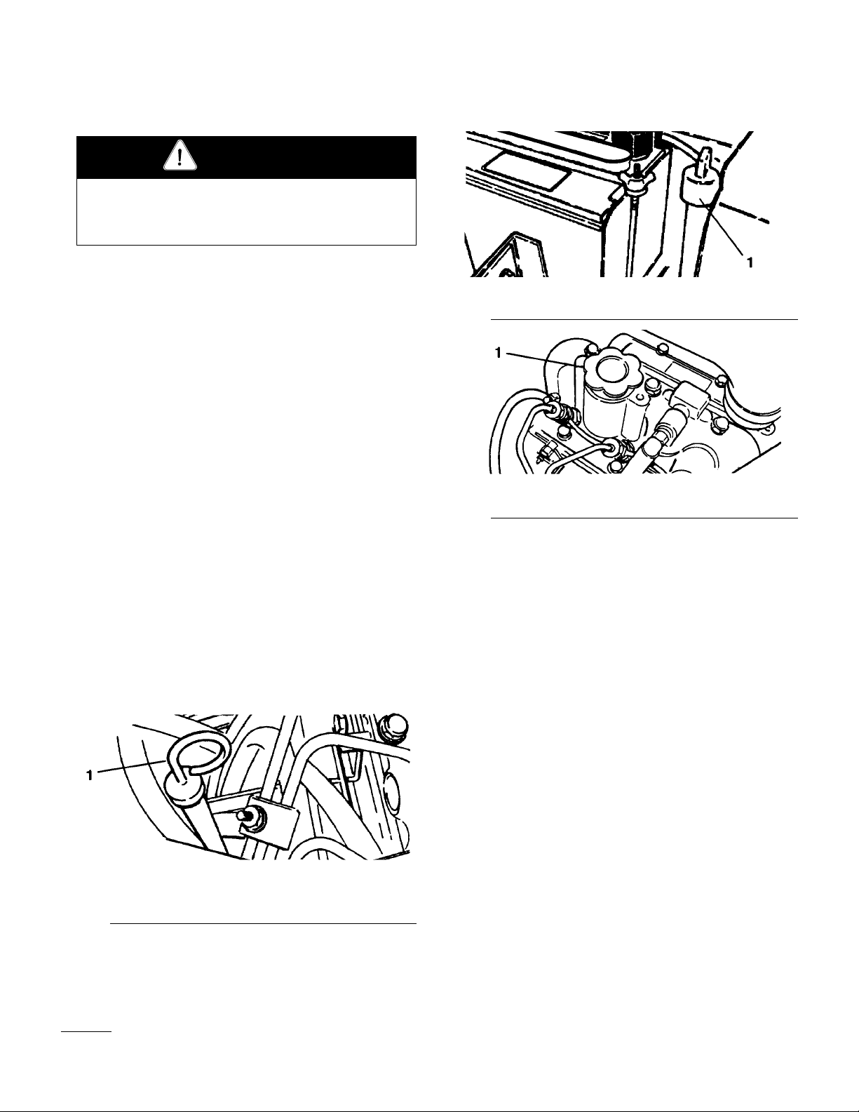
Fuel Shut-off Valves, Diesel Models (Fig. 16 & 17)—
Close the fuel shutoff valves under the fuel tank and on
the fuel filter when storing the machine.
1. Deck engagement control Pull out—Two-wheel drive
Figure 14
Push in—Three-wheel drive
Seat Adjustments (Fig. 15)
Fore and Aft Adjustment—Move the lever on the side of
the seat outward, slide the seat to the desired position
and release the lever to lock the seat into position.
Deluxe Seat Adjustments (Fig. 15)
Weight Adjustment—Push the lever up or down to adjust
to the operator’s weight. Lever up—light operator, lever
in middle position—medium weight operator or lever
down for heavy operator.
Inclining Backrest—Turn the handle to adjust the backrest angle. (Deluxe Seat only).
16
1. Fuel shut off (under the fuel tank)
Figure 16
Figure 17
1. Fuel shut off (on the fuel filter)
Page 17

Fuel Shut-off Valves, Diesel Models (Fig. 16 & 17)—
Close the fuel shutoff valves under the fuel tank and on
the fuel filter when storing the machine.
Operating Instructions
Controls
DIESEL MODELS: ST AR TING/
STOPPING THE ENGINE
IMPORTANT: The fuel system may have to be bled
if any of the following situations have occurred:
A. Initial start up of a new engine.
B. The engine has ceased running due to lack of
fuel.
C. Maintenance has been done on fuel system com-
ponents; i.e., the filter replaced, etc.
Refer to Bleeding The fuel System
1. Be sure the parking brake is set and the reel drive
switch is in DISENGAGE.
2. Remove your foot from the traction pedal and make
sure the pedal is in the neutral position.
the lift lever and the reel drive switch to be sure all
parts operate correctly.
Turn the steering wheel to the left and right to
check steering response. Then shut the engine off
and check for oil leaks, loose parts and any other
noticeable malfunctions.
CAUTION
If the engine has been running, pressurized hot
coolant can escape when the radiator cap is
removed and cause burns.
6. To stop the engine, move the throttle control down-
ward to IDLE, move the reel drive switch to DISENGAGE and turn the ignition key to OFF.
Remove the key from the switch and install the
switch cover to prevent accidental starting.
3. Move the throttle lever to the full throttle position.
4. Remove the cover from the ignition switch. Insert
the key and turn it counterclockwise to the GLOW
PLUG position—and hold it there for approximately 20 to 30 seconds. Then, turn the key clockwise
to START to engage the starter motor. Release the
key when the engine starts. The key will move
automatically to ON.
IMPORTANT To prevent overheating the starter
motor, do not engage the starter longer than 10
seconds. After 10 seconds of continuous cranking, wait 60 seconds before engaging the starter
motor again.
5. When starting the engine for the first time, or after
an engine overhaul, operate the machine in forward
and reverse for one to two minutes. Also operate
7. Close the fuel shut-off valves before storing the
machine.
DIESEL MODELS: BLEEDING
THE FUEL SYSTEM
1. Park the machine on a level surface. Make sure the
fuel tank is at least half full.
2. Unlatch and raise the hood.
3. Open the fuel shut-off valve under the fuel tank and
on the fuel filter.
4. Open the (2) bleed screws on the side of the fuel
filter mounting head, allowing the bowl to re-fill
with fuel. Close bleed screws when the bowl is
filled.
17
Page 18

Operating
DANGER
Because diesel fuel is flammable, use caution
when storing or handling lt.
• Do not smoke while filling the fuel tank.
• Do not fill the fuel tank while the engine
is running, hot, or when the machine is in
an enclosed area.
• Always fill the fuel tank outside and wipe
up any spilled diesel fuel before starting
the engine.
• Store fuel in a clean, safety-approved container and keep the cap in place. Use
diesel fuel for the engine only; not for any
other purpose.
8. Pump the priming lever until a steady stream of
fuel flows out of the injection pump inlet screw,
then tighten the screw.
1. Fuel shutoff
Figure 18
2. Bleed screws (2)
3. Bowl
5. On the left side of the engine (below the alternator)
find the transfer pump inlet screw. Note the angle
of the fitting on the transfer pump inlet and loosen
the screw (left screw only).
6. When a steady stream of fuel flows out of the trans-
fer pump screw, tighten the screw, retaining the
angle of fitting before it was loosened.
1. Transfer pump screw
Figure 19
2. Injection pump Inlet screw location
3. Injection pump inlet screw
4. Priming lever
5. Note fitting angle
DIESEL MODELS: BLEEDING
THE COOLING SYSTEM
If the system is being completely filled or more than a
quart of coolant is being added to the system, the cooling system may need to be bled.
1. Unlatch and raise the hood.
2. Remove the radiator cap.
CAUTION
If the engine has been running, pressurized hot
coolant can escape when the radiator cap is
removed and cause burns.
7. Loosen the injection pump inlet screw on the right
side of the engine.
18
Page 19

Operating
3. Remove the square plug from the radiator hose.
4. Slowly fill the radiator with a 50/50 solution of
water and permanent ethylene glycol anti-freeze
until it comes out the plug opening in the hose.
5. Reinstall the hose plug and finish filling the radia-
tor.
Figure 20
1. Hose plug
motor, do not engage the starter longer than 10
seconds. After 10 seconds of continuous cranking, wait 60 seconds before engaging the starter
motor again.
5. When starting the engine for the first time, or after
an engine overhaul, operate the machine in forward
and reverse for one to two minutes. Also operate
the lift lever and the reel drive switch to be sure all
parts operate correctly.
Turn the steering wheel to the left and right to
check steering response. Then shut the engine off
and check for oil leaks, loose parts and any other
noticeable malfunctions.
6. To stop the engine, move the throttle control down-
ward to IDLE, move the reel drive switch to DISENGAGE and turn the ignition key to OFF.
Remove the key from the switch and install the
switch cover to prevent accidental starting.
6. Install the radiator cap.
GASOLINE MODELS: STARTING/ STOPPING THE ENGINE
1. Be sure the parking brake is set and the reel drive
switch is in DISENGAGE.
Note: After the hand brake is released, run the
vehicle in the opposite direction of resistance to fully release the brake.
2. Remove your foot from the traction pedal and make
sure the pedal is in the neutral position.
3. Move the choke lever to the ON position—when
starting a cold engine—and the throttle lever to the
half-throttle position.
4. Insert the key into the ignition switch and turn it
clockwise to start the engine. Release the key
when the engine starts. Regulate the choke to keep
the engine running smoothly.
IMPORTANT To prevent overheating the starter
CAUTION
Do not disconnect the safety switches because they
are for the operator’s protection. Check the safety
switch operation dally to be sure the system operates correctly. If a switch is not operating correctly, replace it before operating the machine. Replace
the switches every two years to be sure of maximum
safety.
7. Close the fuel shut-off valves before storing the
machine.
CHECK OPERATION OF INTERLOCK SWITCHES
1. With the operator off the seat, the traction pedal in
neutral and the cutting unit clutch switch in disengage, the engine should start. If either the traction
pedal is depressed or the cutting unit clutch switch
is engaged, with the operator off the seat, the
engine should stop. Correct the problem if the
safety switches are not operating correctly.
2. With the operator on the seat, the engine running,
and the cutting unit clutch switch engaged, the
19
Page 20

Operating
clutch should be engaged, the dash indicator light
glowing and the jackshaft turning when the lift
cylinder is fully retracted. As the lift cylinder is
extended, the light should go out, the clutch disengage and the jackshaft stop turning. Correct the
problem if the safety switches are not operating
correctly.
3. With the operator on the seat, the engine running,
the clutch switch engaged, the cutting units lowered
and the lift cylinder fully retracted, the reels should
turn and the dash indicator light should glow. If the
reels do not turn and the light does not glow, an
adjustment to the cutting unit interlock switch may
be necessary.
A. Stop the engine and set the parking brake.
B. Make sure the cutting units are completely
lowered and the lift cylinder is fully retracted.
C. Locate the cutting unit interlock switch on the
left side of the machine on the bottom of the
hydraulic cylinder.
3. Adjust the steering column to the desired operating
position and reinstall the capscrew.
TO WING THE TRACTION UNIT
In case of emergency, the Reelmaster 216-D can be
towed for a short distance. However, Toro does not recommend this as a standard procedure.
IMPORTANT Do not tow the machine faster than
3–4.8 kmh (2–3 mph) because the drive system
may be damaged. If the machine must be
moved a considerable distance, transport it on
a truck or trailer.
1. Turn the by-pass valve on pump counterclockwise
until it is fully open.
D. Turn the screw out until the switch is activated.
Check continuity when the switch is activated.
E. Check operation and repeat adjustment, if nec-
essary.
ADJUST THE STEERING COLUMN
1. Raise the hood.
2. Remove the capscrew securing the steering column
to the frame bracket.
1. By-pass valve
Figure 22
2. Before starting the engine, close the by-pass valve
securely by rotating it clockwise. Do not exceed
7–11 Nm (5–8 ft-lb) torque. Do not start the
engine when the valve is open.
TRAINING PERIOD
Before mowing with the Reelmaster, The Toro Company
suggests you find a clear area and practice starting and
stopping, raising and lowering the cutting units, turning,
etc. This training period will help the operator gain confidence in the performance of the Reelmaster.
1. Steering column
2. Frame bracket
20
Figure 21
Page 21

Operating
BEFORE MOWING
Inspect the area for debris and clear it if necessary.
Determine the direction best to mow on the previous
mowing direction. Always mow in an alternate pattern
from the previous mowing, so that the grass blades will
be less apt to lay down and therefore be difficult to gather between the reel blades and bedknife.
OPERATING CHARACTERISTICS
Practice operating the Reelmaster and become thoroughly familiar with it. Because of its hydrostatic transmission and choices of either two or three wheel drive, its
characteristics differ from many turf maintenance
machines. Points to consider when operating are the
traction drive, engine speed and the load on the cutting
units. Regulate the traction pedal to keep the engine
rpm high and somewhat constant while mowing to maintain adequate power for the traction and cutting units.
Adjust the speed selector to maintain constant ground
speed and quality of cut. However, when on hilly terrain, do not use the speed selector.
INSPECTION AND CLEAN-UP
AFTER MOWING
After mowing, thoroughly wash the machine with a garden hose—without a nozzle so excessive water pressure
will not cause contamination and damage to seals and
bearings.
Make sure the radiator screen, radiator and the oil cooler(diesel models) and cooling fins and area around the
engine cooling air intake (gasoline models) are kept free
of dirt or grass clippings. After cleaning, it is recommended
– the machine be inspected for possible hydraulic
fluid leaks, damage or wear to the hydraulic and
mechanical components
– the cutting units be checked for sharpness and cor-
rect reel-to-bedknife adjustment.
CUTTING UNIT
CHARACTERISTICS
Follow the operating guidelines in this manual and know
how to operate the machine safely on all types of terrain.
Never traverse or mow up and down on slopes over 20
degrees, nor traverse or mow side hills in excess of 15
degrees. Always plan well ahead to avoid the need for
sudden stops, starts or turns. To stop, use the reverse
pedal for braking. Before stopping the engine, disengage all controls, move the throttle to IDLE, and set the
parking brake.
TRANSPORT OPERATION
Be sure the cutting units are in the fully up position,
move the traction pedal stop from under the pedal to
allow full traction pedal travel and place the throttle control FAST. While operating on slopes and uneven terrain, always reduce speed and use extreme caution
before turning to reduce risk of tipping or losing control.
Watch carefully for, and avoid, holes in the terrain, sudden drop-off s and other hidden hazards. To prevent
costly damage and downtime, familiarize yourself with
the width of the Reelmaster. Do not attempt to pass
between immovable objects placed close together.
The single-knob, bedknife-to-reel adjustment system
simplifies the adjustment needed to deliver optimum
mowing performance. The precise adjustment that is
possible gives the necessary control to provide a continual self-sharpening action—thus maintaining sharp cutting edges, assuring good quality-of-cut, and greatly
reducing the need for routine backlapping.
Also, the rear roller positioning system permits optimum
bedknife altitude and location for varying cutting heights
and turf conditions.
CUTTING UNIT DAILY
ADJUSTMENTS
Before each day’s mowing, or as required, check each
cutting unit to verify correct bedknife-to-reel contact.
This must be performed even though quality of cut is
acceptable.
1. Shut off the engine and lower the cutting units onto
a hard surface.
21
Page 22

Operating
2. Release belt tension to the cutting units, refer to
Releasing Belt Tension to the Cutting Units.
3. Slowly turn the reel in reverse direction, listening
for reel-to-bedknife contact. If no contact is evident, turn bedknife adjusting knob clockwise, one
click at a time, until light contact is felt and heard.
4. If excessive contact is felt, turn the bedknife adjust-
ing knob counterclockwise, one click at a time until
no contact is evident. Then turn the bedknife
adjusting knob one click at a time clockwise, until
light contact is felt and heard.
IMPORTANT Light contact is preferred at all
times. If light contact is not maintained, bedknife/ reel edges will not sufficiently self-sharpen
and dull cutting edges will result. If excessive
contact is maintained, bedknife/reel wear will be
accelerated, uneven wear can result, and quality
of cut may be adversely affected.
Note: As the reel blades continue to run against the
bedknife, a slight burr will appear on the front cutting edge surface the full length of the bedknife. If
a file is occasionally run across the front edge to
remove this burr, improved cutting can be obtained.
After extended running, a ridge will eventually develop
at both ends of the bedknife. These notches must be
rounded off or filed flush with the bedknife’s cutting
edge to assure smooth operation.
22
Page 23

Maintenance
LUBRICATION
GREASING BEARINGS AND BUSHINGS
(Fig. 23–31)
The traction unit and cutting unit’s grease fittings must
be lubricated regularly with No. 2 General Purpose
Lithium Base Grease. If the machine is operated under
normal conditions, lubricate bearings and bushings after
every 25 hours of operation. Bearings and bushings
must be lubricated daily when operating conditions are
extremely dusty and dirty. Dusty and dirty operating
conditions could cause dirt to get into the bearings and
bushings, resulting in accelerated wear.
The traction unit bearings and bushings that must be
lubricated are:
Steering column (Fig. 23), steering gears (2) (Under
skirt below steering sector) steering shaft (2) (Fig. 24),
jackshaft pulley bearing (2) (Fig. 25), lift arms (3) (Fig.
26) pivot rods (3) (Fig. 27), and belt tensioners (3) (Fig.
28).
Figure 24
Figure 25
Also, apply grease to slots in cylinder support (Fig. 29).
The cutting unit lubrication points are: Single point
adjustment knob (2) (Fig. 30), reel flange bearing (2)
and front and rear rollers (Fig. 31).
Figure 23
Figure 26
Figure 27
23
Page 24

Maintenance
Figure 28
Figure 29
Figure 30
Figure 31
24
Page 25

CAUTION
Before servicing or making adjustments to the
machine, stop the engine and remove the key
from the switch.
Maintenance
FILTER
Service the air cleaner filter every 400 hours, or more
frequently in extremely dusty or dirty conditions, by
washing or using compressed air. Replace the element
after every four cleanings (1,600 hour) or annually,
whichever comes first.
DIESEL MODELS: SERVICING
THE AIR CLEANER DUST CUP,
BAFFLE, AND FILTER
Inspect the dust cup and rubber baffle once a week or
every 50 hours operation. However, daily or more frequent inspection is required when operating conditions
are extremely dusty and dirty. Never allow dust to build
up closer than one inch from the rubber baffle.
1. Loosen the thumb screw until the dust cup is
removed. Separate the dust cup and baffle.
2. Dump the dust out of the dust cup. After cleaning
the cup and baffle, assemble and reinstall both
parts.
Washing Method
IMPORTANT: Do not remove the plastic fin assembly because washing removes dust from beneath the
fins.
1. Prepare a solution of filter cleaner and water and
soak the filter element about 15 minutes.
2. After soaking the filter for 15 minutes, rinse it with
clear water.
3. Dry the filter element using warm, flowing air no
hotter than 71° C, or allow the element to air dry.
Do not use compressed air or a light bulb to dry the
filter element because they may damage it.
Compressed Air Method
IMPORTANT: Do not remove the plastic fin assembly because this method removes dust from beneath
the fins.
1. Dust Cup & Baffle
2. Filter Element
3. Air Cleaner Body
Figure 32
1. Blow compressed air from inside to the the outside
of the dry filter element. Do not exceed 689 kPa
(100 psi) to prevent damage to the filter.
2. Keep the air hose nozzle at least 3 cm from the
pleated paper, and move the nozzle up and down
while rotating the filter element.
GASOLINE MODELS: SERVICING THE AIR CLEANER
The foam pre-cleaner must be cleaned and reoiled after
every 25 hours of engine operation if the engine is operated in clean air conditions. However, the air cleaner
must be cleaned every few hours if operating conditions
are extremely dusty or sandy.
25
Page 26

Maintenance
1. Remove the lock nut and cover.
2. Remove the foam pre-cleaner by sliding it off the
paper element.
3. Wash the pre-cleaner in detergent and warm water.
Then wrap it in a cloth and squeeze it dry. Do not
wring it. Next, saturate the precleaner in engine oil
and squeeze it to remove excess oil.
4. Install the cleaned pre-filter on the paper cartridge.
Inspect the paper element every 50 hours of operation
and replace it when it is dirty or damaged. Do not wash
the paper element or clean it with compressed air.
CHANGING ENGINE OIL AND THE
OIL FILTER
Diesel models:
Change the oil and the oil filter initially after the first
20 hours of operation, thereafter change the oil every 50
hours and the oil filter every 100 hours.
1. Locate the engine the oil drain plug on bottom, rear
of the oil pan. Remove the drain plug and let the
oil flow into the drain pan. When the oil stops,
install the drain plug.
2. Locate the engine filter on the rear of the engine.
Remove the oil filter. Apply a light coat of clean
oil to the new filter seal before screwing it on. DO
NOT OVER-TIGHTEN.
3. Add oil to the crankcase.
Gasoline models:
1. Air cleaner cover
1. Foam pre-cleaner
Figure 33
Figure 34
For new engines, change the oil after the first 5 operating hours. Thereafter, under normal conditions change
the oil after every 25 hour of engine operation. Change
more often if you operate the engine in dusty or dirty
conditions.
If possible, run the engine just before changing the oil,
which will make the oil flow more freely and carry more
contaminants.
Figure 35
1. Crankcase drain plug (gasoline engines)
26
Page 27

CHANGING THE SPARK PLUG
(GASOLINE ENGINES)
Check the condition of the electrodes at 100-hour intervals. The correct spark plug for the engine is Champion
RH-10 or equivalent. Set the air gap at .125 in.
CHANGING THE HYDRAULIC SYSTEM FLUID AND FILTER
The hydraulic system filter must be changed after the
first five hours of operation, and after that, every 250
hours of operation or yearly, whichever comes first. Use
a genuine Toro oil filter for replacement. The hydraulic
fluid must be changed every 500 hours of operation or
yearly, whichever comes first.
1. Park the machine on a level surface, lower the cut-
ting units, set the parking brake and turn the engine
off.
2. If only the filter is to be changed, remove the reser-
voir cap and insert the reservoir plug (Fig. 35), to
the block outlet.
Maintenance
Figure 37
1. Hydraulic oil filter
4. Apply a film of oil on the filter gasket. Install the
filter by hand until gasket contacts mounting head;
then tighten the filter an additional three-fourths of
a turn.
5. Fill the reservoir to the correct level.
6. Place all controls in the neutral or disengaged posi-
tion and start the engine. Run the engine at the
lowest possible rpm to purge the system of air.
7. Run the engine until the lift cylinder extends and
retracts and forward and reverse wheel motion is
achieved.
1. Reservoir plug
Figure 36
2. Reservoir outlet
This will retain most of the fluid in the reservoir
when the filter is removed.
3. Clean the area around the hydraulic oil filter.
Remove the filter from the bottom of the filter
housing and allow the oil to flow into a drain pan.
Use a bottom type filter wrench.
8. Stop the engine and check the oil level in the reser-
voir; add oil if necessary.
9. Check all connections for leaks.
BA CKLAPPING THE CUTTING
UNITS
The cutting units may be backlapped on the machine.
Backlap Kit, Part no. 84-5510 is available from your
authorized TORO distributor.
Backlap according to the procedures in the Toro
Sharpening Reel and Rotary Mowers Manual Form No.
80-300 PT.
27
Page 28

Maintenance
CAUTION
Be careful when lapping the reel because contact with the reel or other moving parts can
result in personal injury.
CAUTION
Under no circumstances use a short-handled
paint brush. The 29-9100 handle assembly or
individual parts are available from your local
authorized TORO distributor.
MODEL AND SERIAL NUMBER
The mower has two identification numbers: a model
number and a serial number. The two numbers are
stamped into a plate that is riveted to the frame at the
rear of the mower. In any correspondence concerning
the mower, supply the model and serial numbers to
assure that correct information and replacement parts are
obtained.
Note: Do not order by reference number if a parts catalog is being used; use the part number.
To order replacement parts from an Authorized TORO
Service Dealer, supply the following information:
1. Model and serial numbers of the mower.
2. Part number, description and quantity of part(s)
desired.
Cutting Unit Set Up and Adjustment
SET HEIGHT OF CUT AND LEVEL
THE REAR ROLLER
(Floating Cutting Unit)
1. Position the cutting unit on a flat level table or
board.
2. Slightly loosen (crack) the nut securing each roller
bracket to the angle bracket.
3. Adjust the support capscrew to achieve a 1-inch ±
1
⁄16 inch dimension between the height-of-cut sup-
port and the front roller bracket (2 places).
5
4. Adjust the support capscrew to achieve
1
⁄16 inch dimension between the height-of-cut sup-
port and the rear roller bracket (2 places).
⁄8 inch ±
ting as indicated on height-of-cut plate.
Figure 38
1. Roller bracket
2. Angle bracket
3. Height-of-cut pin
4. Support capscrew
5. Locknuts
5. Remove the hairpin cotters securing the rear
1
height-of-cut pins and reinstall in the
28
⁄2-inch set-
6. Remove the hairpin cotters securing the front
height-of-cut pins and reinstall in the
1
⁄4-inch set-
Page 29

ting as indicated on the height-of-cut plate to allow
clearance between the roller and table.
1
7. Position a
⁄2 inch or thicker bar under the reel
blades and against the front face of the bedknife.
Make sure the bar covers the full length of the reel
blades.
8. Verify if the rear roller is level by inserting a piece
of paper under each end of the roller.
Cutting Unit
9. Level the roller by adjusting the appropriate support
capscrew on the rear roller supports until the roller
is parallel and entire length of the roller contacts
table.
10. When the roller is level, adjust both rollers to the
desired height-of-cut pins. Tighten the nuts securing the roller brackets.
SET HEIGHT OF CUT AND LEVEL
THE REAR ROLLER
(Fixed Cutting Units)
1. Position the cutting unit on flat level surface or
board.
2. Slightly loosen (crack) the nuts securing the roller
brackets to the angle brackets.
5
3. Adjust the support capscrews to achieve
1
⁄16 inch dimension between the height-of-cut sup-
port and the roller bracket (2 places).
4. Remove the hairpin cotters securing the height-of-cut
pins and install them in the hole at the desired setting indicated on the height-of-cut plate.
5. Use a gauge block with a height equal to the
desired height of cut and position it against the
front edge of the bedknife at one end. Turn the
support capscrew to adjust the height of the bedknife equal to the gauge block.
6. Repeat the procedure at the other end, then recheck
the original end.
⁄8 inch ±
1. Roller bracket
Figure 39
2. Angle bracket
3. Height-of-cut pin
4. Support capscrew
7. Tighten the nuts securing the roller brackets.
8. After initial set-up, you may change the height of
cut by repositioning the height-of-cut pins to the
desired setting.
ADJUST THE BEDKNIFE PARALLEL TO THE REEL
(Floating or Fixed Cutting Units}
1. Make sure the reel contact is removed by turning
the bedknife adjustment knob counterclockwise
(Fig. 40). Tip the cutting unit to gain access to the
reel and the bedknife (Fig. 41).
2. On either end of the reel, insert a long strip of dry
newspaper between the reel and the bedknife.
While slowly rotating the reel into bedknife, turn
the bedknife adjusting knob clockwise one click at
a time until the paper is pinched lightly, which
results in a slight drag when paper is pulled.
3. Check for light contact at the other end of the reel
using paper. If light contact is not evident, go to
the next step
4. Loosen (2) carriage bolts on the bedbar adjuster
(Fig. 42).
5. Adjust the nuts to move the bedbar adjuster up or
29
Page 30

Cutting Unit
down until the paper is pinched along the entire
bedknife surface when the bedknife adjustment
knob is adjusted to no more than two clicks beyond
first contact of the reel bedknife (Fig 41).
6. Tighten the nuts and carriage bolts and verify
adjustment
1. Bedknife adjusting screw
Figure 40
Figure 41
1. Roller bracket
2. Angle bracket
3. Height-of-cut pin
4. Support capscrew
1. Bedbar adjuster
Figure 42
2. Carriage bolts
3. Adjustment nuts
VERIFY HEIGHT-OF-CUT SETTING
(Floating Cutting Unit)
1. On the gauge bar, set the head of the screw to the
desired height of cut (Fig. 43) This measurement is
from the bar face to the underside of the screw
head. The gauge bar (Toro Part No. 138199) may
be obtained from your local Toro Distributor
30
1. Gauge bar
Figure 43
2. Front roller support screw
2. Slightly loosen (crack) the nut securing each front
roller bracket to the angle bracket.
3. Place the bar across the front and rear rollers and
adjust the front roller support screws until the
underside of the screw head engages the bedknife
cutting edge. Do this on both ends of the reel.
Page 31

Cutting Unit
4. Tighten the nuts securing the roller brackets.
MOUNT THE CUTTING UNITS
(Floating Cutting Unit)
1. Slide a thrust washer onto the lift arm pivot rod.
Figure 44
1. Thrust washer
2. Carrier frame
3. Flatwasher and flange head capscrew
2. Slide the cutting unit carrier frame onto pivot rod
and secure with a flatwasher and capscrew. l
2. Slide the cutting unit support onto the pivot rod and
secure with a flat washer and flange head capscrew.
Note: Position the thrust washer between the rear of
the cutting unit support and flatwasher on the rear
cutting unit.
Note: When mounting the rear cutting unit, position
the thrust washer between the cutting unit support
and the flatwasher at the rear.
3. The front cutting units should be parallel to the
front wheels. To adjust, loosen the capscrews
securing the supports to the cutting units, adjusting
the cutting units until they are parallel, then tighten
screws.
INSTALL THE CUTTING UNIT
DRIVE BELTS
(Floating Cutting Units)
1. Route (3) V-belts (two in loose parts) around the
jackshaft pulleys and reel pulleys (Fig 46).
MOUNT THE CUTTING UNITS
(Fixed Cutting Units)
1. Slide a thrust washer onto the lift arm pivot rod
(Fig 45).
Figure 45
1. Thrust washer
2. Cutting unit Support
3. Flatwasher & flange head capscrew
4. Cutting unit support
1. Cutting unit drive belt
Figure 46
2. Carrier frame
3. Shoulder bolt, (2) flatwashers & nut
4. Tensioner bracket
5. Belt tensioner
31
Page 32

Cutting Unit
INSTALL THE CUTTING UNIT
DRIVE BELTS
(Fixed Cutting Units)
1. Route (3) V-belts around the jackshaft pulleys and
reel pulleys.
Figure 47
1. Tensioner bracket
2. Belt tensioner
3. Capscrew, (2) flatwashers, spacer & nut
INSTALL BELT TENSIONERS TO
THE CUTTING UNITS
(Fixed Cutting Units)
1. On the pulley end of the front cutting units and
both ends of the rear cutting unit, install a washer,
spacer, belt tension rod and spacer on a capscrew
(Fig 46).
Note: Position belt tension rods in locked position
when installing. Loosen the jam nut and rotate the
rod to adjust the rod length for installation.
2. Secure with the nut.
ADJUST THE PULLEY CLEANERS
1. Adjust the cleaner bracket so it is centered in the
groove of the pulley and tighten the carriage bolt
and locknut.
INST ALL THE BEL T TENSIONERS
TO THE CUTTING UNITS
(Floating Cutting Units)
1. On pulley end of the front cutting units and both
ends of the rear cutting unit, remove the nut from
the bolt securing the carrier frame to the tensioner
bracket (Fig. 46).
2. Install a spacer belt tension rod and washer onto the
capscrew.
Note: Position the belt tension rods in locked position when installing. Loosen the jam nut and rotate
the rod to adjust the rod length for installation.
3. Reinstall the nut previously removed.
2. Adjust the cleaner bracket so there is approximately
.030–.060 clearance between the bracket and pulley, then tighten the capscrew and locknut.
Figure 48
1. Cleaner bracket
32
Page 33

Cutting Unit
INSTALL COUNTERBALANCE
SPRINGS
1. Hook one end of the spring into the second hole
(from bottom) on the cutting unit lift tab (Fig. 49).
Figure 49
1. Cutting unit lift tab
2. On the front cutting units secure other end of the
spring to the appropriate hole (see chart) on the
counterbalance arm with the spring shackle, (2) clevis pins and (2) cotter pin.
vis pins and (2) cotter pins.
A. Second hole from Bottom—for 5-blade reel
application
B. Middle hole—for 8-blade reels without baskets
C. Top hole—for 8 blade reels using baskets
Figure 51
1. Rear counter balance spring
2. Chain links
3. Vinyl cover
4. Spring shackle
IMPORTANT: These are recommended settings.
Readjust the spring positions to attain optimum performance. By raising the spring locations on the
counterbalance arms, the cutting unit weight on the
ground is reduced and traction is increased.
1. Counterbalance arm
Figure 50
2. Spring shackle
3. Clevis pin & cotter pin
Note: On the rear counterbalance spring, install a
vinyl cover over the spring before installing.
3. On the rear cutting unit, secure the other end of the
spring to the appropriate hole (see chart) in the
counterbalance arm with (2) chain links (5-, 8- &
11-blade floating cutting units) or (3) chain links
(5-blade fixed cutting units) spring shackle (2) cle-
4. To tension the counterbalance springs proceed as
follows:
A. Remove the cotter pin and clevis pin securing
the spring shackle to the counterbalance arm.
Do not remove the other clevis pin.
B. Move the shackle up or down on counterbal-
ance arm until aligned with the desired hole of
the arm. Reinstall the clevis pin and cotter
pin.
33
Page 34

Page 35

Page 36

 Loading...