

Page 1

OperatorCoolingFan
Groundsmaster
Sunshade
ModelNo.03247
Installation
LooseParts
Usethechartbelowtoverifythatallpartshavebeenshipped.
FormNo.3430-932RevA
®
orReelmaster
®
TractionUnitwithUniversal
InstallationInstructions
ProcedureDescription
1
2
3
4
5
6
Nopartsrequired
Nopartsrequired
Nopartsrequired
Longfan-mountbracket
Coolingfan
Shortfan-mountbracket
Carriagebolt(1/4x5/8inch)
Flangelocknut(1/4inch)
Fanswitch1
Jamnut1
Knob1
Fan-speedcontroller1
Thread-formingscrew(#8x3/8inch)
Wireharness1
Cableties
Fuse(25A)
Nopartsrequired
Qty.
Use
–
–
–
1
1
1
4
4
2
4
1
–
Preparethemachine.
Removethesunshade.
Installtheswitchpanelkit.
Installthecoolingfan,fan-speed
controller,andswitch.
Installthewireharness.
Connectthebattery.
7
8
©2019—TheToro®Company
8111LyndaleAvenueSouth
Bloomington,MN55420
Nopartsrequired
Nopartsrequired
Registeratwww.T oro.com.
–
–
Adjustthecoolingfanposition.
Installthesunshade.
OriginalInstructions(EN)
PrintedintheUSA
AllRightsReserved
*3430-932*A
Page 2
1
PreparingtheMachine
NoPartsRequired
Procedure
1.Parkthemachineonalevelsurface.
2.Shutofftheengine,engagetheparkingbrake,
andremovethekeyfromtheignitionswitch.
3.Disconnectthebattery;refertotheelectrical
systemmaintenancesectionofyourOperator’s
Manual.
g244328
Figure2
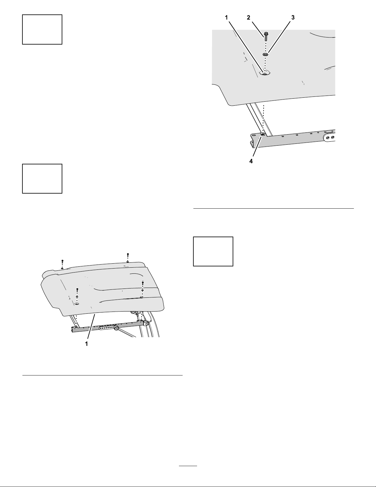
2
RemovingtheSunshade
NoPartsRequired
Procedure
1.Sunshade
Figure1
1.Grommet3.Washer(5/16inch)
2.Flange-headbolt(5/16x
1-1/4inches)
2.Removethesunshadefromthemachine(Figure
1).
4.Clipnut(side-frame
channel)
3
InstallingtheOptional
SwitchPanelKit
NoPartsRequired
Procedure
g244329
IftheoptionalSwitchPanelKitisnotinstalled,install
it;refertotheinstallationinstructionsfortheswitch
panelkit.
1.Removethe4ange-headbolts(5/16x1-1/4
inches)and4washers(5/16inch)thatsecure
thesunshadetotheside-framechannels(Figure
1andFigure2).
Note:Donotremovethegrommetsfromthe
sunshade.
2
Page 3
4
InstallingtheCoolingFan,
FanSwitch,andFan-Speed
Controller
Partsneededforthisprocedure:
1
Longfan-mountbracket
1
Coolingfan
1
Shortfan-mountbracket
4
Carriagebolt(1/4x5/8inch)
4
Flangelocknut(1/4inch)
1Fanswitch
1Jamnut
1Knob
1Fan-speedcontroller
2
Thread-formingscrew(#8x3/8inch)
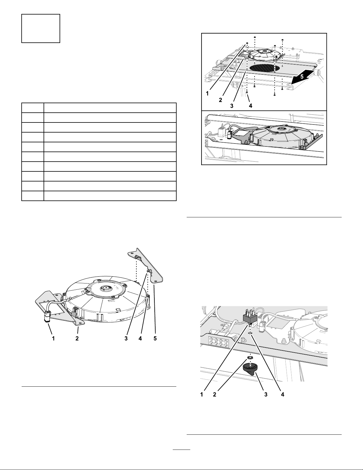
InstallingtheCoolingFan
1.Locatethe2slotsinthecooling-fanhousing
closesttothefanharnesswiththe2-socket
connector(Figure3).
4.Aligntheholesinthefanmountbracketstothe
holeintheswitchpanelasshowninFigure4.
Figure4
1.Flangelocknut(1/4inch)4.Carriagebolt(1/4x5/8
2.Longfan-mountbracket
3.Switchpanel
inch)
5.Frontofmachine
5.Assemblethecoolingfanandbracketstothe
switchpanel(Figure4)with4carriagebolts(1/4
x5/8inch)and4angelocknuts(1/4inch).
6.Torquetheangelocknutsto1017to1243N∙cm
(90to110in-lb).
g244454
Figure3
1.2-socketconnector
2.Longfan-mountbracket5.Shortfan-mountbracket
3.Mountingtab
4.Slot(cooling-fanhousing)
2.Insertthe2mountingtabsofthelongfan-mount
bracketintotheslotsinthefanhousing(Figure
3)thatyouidentiedinstep1.
3.Insertthe2mountingtabsoftheshortfan-mount
bracketintotheother2slotsinthecooling-fan
housing(Figure3).
InstallingtheFanSwitch
1.Aligntheatontheoutershaftofthefan-switch
shaftwiththeD-shapedholeintheswitchpanel
(Figure5).
g244453
g244490
Figure5
1.Flat(fan-switchshaft)
2.Jamnut4.D-shapedhole
3.Knob
3
Page 4

2.Insertthefan-switchshaftthroughtheholein
thepanelandsecuretheswitchwiththejamnut
(Figure5).
3.AligntheD-shapedholeintheknobwiththeat
ontheinnershaftofthefan-switchshaft(Figure
5).
4.Presstheknobontotheswitchuntilknobisfully
seated(Figure5).
InstallingtheFan-SpeedController
1.Alignthefan-speedcontrollertotheangeof
thelongfan-mountbracketwiththeelectrical
terminalsaligntowardthebackofthemachine
(Figure6).
5
InstallingtheWireHarness
andFuse
Partsneededforthisprocedure:
1Wireharness
4
Cableties
1
Fuse(25A)
InstallingtheWireHarness
1.Alignthewireharnessofthekittotheswitch
panelasshowninFigure7.
Figure6
1.Frontofthemachine3.Longfan-mountbracket
2.Fan-speedcontroller
2.Securethefan-speedcontrollertotheangeof
thelongfan-mountbracket(Figure6)withthe2
thread-formingscrew(#8x3/8inch).
4.Thread-formingscrew(#8
x3/8inch)
g244491
g244638
Figure7
1.Kit-wireharness
2.Connectthesocketterminalsofthekitwire
harnesstothebladeterminalsofthefan-speed
controller(Figure8)asshowninthefollowing
table:
WireHarness—WireColor
fortheSocketT erminals
Violet1—Low
Brown2—Medium
Orange
Optional
Pink5—Motor
Fan-Speed
Controller—BladeTerminal
3—High1
4—High2
4
Page 5

Figure8
1.Violet(wire-harness
terminallabeledRESISTOR
MODULEL)
2.Bladeterminal1
(Low—fan-speed
controller)
3.Bladeterminal2
(Medium—fan-speed
controller)
4.Bladeterminal3(High
1—fan-speedcontroller)
5.Bladeterminal
4—Optional(High
2—fan-speedcontroller)
6.Bladeterminal5—Motor
(fan-speedcontroller)
7.Pink(wire-harness
terminallabeledMOTOR
(+))
8.Orange(wire-harness
terminallabeledRESISTOR
MODULEH)
9.Brown(wire-harness
terminallabeledRESISTOR
MODULEM)
3.Atthe20cm(8inch)branchofthekitwire
harness,connectthe2-socketconnectorinto
the2-pinconnectoroftheadapterwireharness
fortheswitchpanel(Figure9).
g244634
g283647
1.5-socketconnector(kit
wireharness)
2.2-pinconnector(kitwire
harness)
Figure10
3.2-socketconnector
(cooling-fanharness)
4.Fanswitch
5.Connectthe2-pinconnectorofthekitwire
harnessintothe2-socketconnectorofthe
cooling-fanharness(Figure10).
6.Securethewireharnesswiththe4cableties.
Figure9
1.2-socketconnector(20cm
(8inch)branch—kitwire
harness)
2.2-pinconnector(adapter
wireharness—switch
panel)
4.Connectthe5-pinconnectorofthefanswitch
intothe5-socketconnectorofthekitwire
harness(Figure10).
g244633
5
Page 6

InstallingtheFuse
Insetthefuse(25A)intothefuseblockatthesecond
fuseslotfromtheleft(Figure11).
Note:Thefusemaynotneedtobeinstalledifafuse
hasalreadybeeninstalledfromanotherT orokit.
Figure11
•Iftheairstreampositioniscorrect,shutoff
thecoolingfan.
•Iftheoperatorwantstheairstreamofthe
coolingfanmoved,performthefollowing
steps:
A.Shutoffthecoolingfan.
B.Removethe4carriagebolts(1/4x5/8
inch)and4angelocknuts(1/4inch)
thatsecuretheswitchpaneltotheleft
andrightside-framechannels(Figure
12).
g244641
1.Fuse(25A)2.Fuseslot—secondfrom
left(switchpanelfuse
block)
6
ConnectingtheBattery
NoPartsRequired
Procedure
Connectthebattery;refertotheelectricalsystem
maintenancesectionofyourOperator’sManual.
7
AdjustingtheCoolingFan
g244667
Figure12
1.Flangelocknut(1/4inch)3.Carriagebolt(1/4x5/8
inch)
2.Switchpanel4.Side-framechannel
C.Movetheswitchpanelforwardor
rearward(Figure13)toalignthecooling
fanthepositionthatyoudeterminedin
step3.
Note:Youcansetthecoolingfanto1
of5positions.
Position
NoPartsRequired
Procedure
1.Seattheoperatorofthemachineinthe
operator’sseat.
2.Rotatethefanswitchtomedium-fanspeed.
3.Determineiftheoperatorwantstheairstreamof
thecoolingfanmovedforwardorrearward:
6
Page 7

Figure13
D.Assembletheswitchpaneltothe
side-framechannelswiththecarriage
boltsandlocknuts(Figure12)thatyou
removedinstep3B.
E.Torquetheangelocknutsto1017to
1243N∙cm(90to110in-lb).
g244666
Figure14
1.Sunshade3.Washer(5/16inch)
2.Flange-headbolt(5/16x
1-1/4inches)
3.Torquetheange-headboltsto1017to1355
N∙cm(90to120in-lb).
4.Clipnut(side-frame
channel)
g244327
Operation
8
InstallingtheSunshade
NoPartsRequired
Procedure
1.Aligntheholesinthegrommetsofthesunshade
withthe4clipnutsoftheside-framechannels.
2.Assemblethesunshadetotheframechannels
(Figure14)withthe4ange-headbolts(5/16x
1-1/4inches)and4washers(5/16inch)thatyou
removedin2RemovingtheSunshade(page2).
UsingtheCoolingFan
g244665
Figure15
1.Knob(fanswitch)
•T orunthecoolingfan,rotatetheknobforthe
fanswitchclockwisetotheLOW,MEDIUM,orHIGH
fan-speedposition(Figure15).
•T oshutoffthecoolingfan,fullyrotatetheknob
counterclockwisetotheOFFposition(Figure15).
7
Page 8

DeclarationofIncorporation
TheToroCompany,8111LyndaleAve.South,Bloomington,MN,USAdeclaresthatthefollowingunit(s)
conform(s)tothedirectiveslisted,wheninstalledinaccordancewiththeaccompanyinginstructionsontocertain
ToromodelsasindicatedontherelevantDeclarationsofConformity.
ModelNo.
SerialNo.
03247
—
ProductDescriptionInvoiceDescription
OPERATORCOOLINGFANOPERATORCOOLINGFANOPERATORCOOLINGFAN
GeneralDescription
Directive
2006/42/EC,
2014/30/EU
RelevanttechnicaldocumentationhasbeencompiledasrequiredperPartBofAnnexVIIof2006/42/EC.
Wewillundertaketotransmit,inresponsetorequestsbynationalauthorities,relevantinformationonthispartly
completedmachinery.Themethodoftransmissionshallbeelectronictransmittal.
ThismachineryshallnotbeputintoserviceuntilincorporatedintoapprovedT oromodelsasindicatedonthe
associatedDeclarationofConformityandinaccordancewithallinstructions,wherebyitcanbedeclaredin
conformitywithallrelevantDirectives.
Certied:
JohnHeckel
Sr.EngineeringManager
811 1LyndaleAve.South
Bloomington,MN55420,USA
February5,2019
AuthorizedRepresentative:
MarcelDutrieux
ManagerEuropeanProductIntegrity
ToroEuropeNV
Nijverheidsstraat5
2260Oevel
Belgium
 Loading...