

Toro 03200 Reelmaster 3100-D, 03201 Reelmaster 3100-D, 03200, 03220, 03221 Operator's Manual
...Page 1

Reelmaster 3100–D
Traction Unit
Model No. 03200—240000001 and Up
Model No. 03201—240000001 and Up
Model No. 03220
Model No. 03221
Form No. 3350–555
Operator’s Manual
English (EN, GB)
Page 2

Warning
CALIFORNIA
Proposition 65 Warning
Diesel engine exhaust and some of its constituents
are known to the State of California to cause
cancer, birth defects, and other reproductive harm.
Important The engine in this product is not equipped
with a spark arrester muffler. It is a violation of California
Public Resource Code Section 4442 to use or operate this
engine on any forest-covered, brush-covered, or
grass-covered land as defined in CPRC 4126. Other states
or federal areas may have similar laws.
Contents
Page
Introduction 3. . . . . . . . . . . . . . . . . . . . . . . . . . . . . . . . .
Safety 3. . . . . . . . . . . . . . . . . . . . . . . . . . . . . . . . . . . . . .
Safe Operating Practices 3. . . . . . . . . . . . . . . . . . . .
Toro Riding Mower Safety 5. . . . . . . . . . . . . . . . . . .
Sound Pressure Level 7. . . . . . . . . . . . . . . . . . . . . . .
Sound Power Level 7. . . . . . . . . . . . . . . . . . . . . . . .
Vibration Level 7. . . . . . . . . . . . . . . . . . . . . . . . . . . .
Safety and Instruction Decals 7. . . . . . . . . . . . . . . . .
Specifications 11. . . . . . . . . . . . . . . . . . . . . . . . . . . . . . . .
General Specifications 11. . . . . . . . . . . . . . . . . . . . .
Optional Equipment 11. . . . . . . . . . . . . . . . . . . . . . . .
Setup 12. . . . . . . . . . . . . . . . . . . . . . . . . . . . . . . . . . . . . .
Loose Parts Chart 12. . . . . . . . . . . . . . . . . . . . . . . . . .
Install Wheels 13. . . . . . . . . . . . . . . . . . . . . . . . . . . . .
Install Steering Wheel 13. . . . . . . . . . . . . . . . . . . . . .
Activate, Charge and Connect Battery 13. . . . . . . . .
Install Seat 14. . . . . . . . . . . . . . . . . . . . . . . . . . . . . . .
Check Angle Indicator 15. . . . . . . . . . . . . . . . . . . . . .
Install Hood Latch
(European Compliance) 15. . . . . . . . . . . . . . . . . . .
Install Exhaust Guard
(European Compliance) 16. . . . . . . . . . . . . . . . . . .
Install ROPS 16. . . . . . . . . . . . . . . . . . . . . . . . . . . . . .
Install Front Lift Arms 16. . . . . . . . . . . . . . . . . . . . . .
Mount Carrier Frames To Cutting Units 17. . . . . . . .
Mount Cutting Units 18. . . . . . . . . . . . . . . . . . . . . . .
Mount Cutting Unit Drive Motors 19. . . . . . . . . . . . .
Adjust Lift Arms 19. . . . . . . . . . . . . . . . . . . . . . . . . .
Before Operating 21. . . . . . . . . . . . . . . . . . . . . . . . . . . . .
Check Crankcase Oil 21. . . . . . . . . . . . . . . . . . . . . . .
Page
Fill Fuel Tank 21. . . . . . . . . . . . . . . . . . . . . . . . . . . . .
Check Cooling System 22. . . . . . . . . . . . . . . . . . . . . .
Check Hydraulic System Fluid 22. . . . . . . . . . . . . . .
Check Tire Pressure 23. . . . . . . . . . . . . . . . . . . . . . . .
Check Reel To Bedknife Contact 24. . . . . . . . . . . . . .
Check Torque Of Wheel Nuts 24. . . . . . . . . . . . . . . .
Controls 24. . . . . . . . . . . . . . . . . . . . . . . . . . . . . . . . . . . .
Operation 26. . . . . . . . . . . . . . . . . . . . . . . . . . . . . . . . . . .
Starting/Stopping Engine 26. . . . . . . . . . . . . . . . . . . .
Bleeding Fuel System 27. . . . . . . . . . . . . . . . . . . . . .
Check Operation Of Interlock Switches 27. . . . . . . .
Towing Traction Unit 27. . . . . . . . . . . . . . . . . . . . . . .
Operating Characteristics 28. . . . . . . . . . . . . . . . . . . .
Mowing Techniques 29. . . . . . . . . . . . . . . . . . . . . . . .
After Mowing 29. . . . . . . . . . . . . . . . . . . . . . . . . . . . .
Selecting Clip Rate (Reel Speed) 30. . . . . . . . . . . . . .
Standard Control Module (SCM) 31. . . . . . . . . . . . . .
Lubrication 33. . . . . . . . . . . . . . . . . . . . . . . . . . . . . . . . . .
Maintenance 36. . . . . . . . . . . . . . . . . . . . . . . . . . . . . . . . .
Recommended Maintenance Schedule 36. . . . . . . . .
Daily Maintenance Checklist 37. . . . . . . . . . . . . . . . .
Service Interval Chart 38. . . . . . . . . . . . . . . . . . . . . .
Hood Removal 38. . . . . . . . . . . . . . . . . . . . . . . . . . . .
General Air Cleaner Maintenance 39. . . . . . . . . . . . .
Servicing Air Cleaner 39. . . . . . . . . . . . . . . . . . . . . . .
Engine Oil and Filter 39. . . . . . . . . . . . . . . . . . . . . . .
Fuel System 40. . . . . . . . . . . . . . . . . . . . . . . . . . . . . .
Bleeding Air From Injectors 41. . . . . . . . . . . . . . . . .
Cleaning Engine Cooling System 41. . . . . . . . . . . . .
Servicing Engine Belts 42. . . . . . . . . . . . . . . . . . . . . .
Adjusting Throttle 42. . . . . . . . . . . . . . . . . . . . . . . . .
Changing Hydraulic Fluid 43. . . . . . . . . . . . . . . . . . .
Replacing Hydraulic Filter 43. . . . . . . . . . . . . . . . . . .
Checking Hydraulic Lines And Hoses 43. . . . . . . . . .
Adjusting Traction Drive For Neutral 44. . . . . . . . . .
Adjusting Parking Brake 44. . . . . . . . . . . . . . . . . . . .
Battery Care 45. . . . . . . . . . . . . . . . . . . . . . . . . . . . . .
Battery Storage 45. . . . . . . . . . . . . . . . . . . . . . . . . . . .
Fuses 45. . . . . . . . . . . . . . . . . . . . . . . . . . . . . . . . . . . .
Backlapping 45. . . . . . . . . . . . . . . . . . . . . . . . . . . . . .
Electrical Schematic 47. . . . . . . . . . . . . . . . . . . . . . . .
Hydraulic Schematic 48. . . . . . . . . . . . . . . . . . . . . . .
Storage 49. . . . . . . . . . . . . . . . . . . . . . . . . . . . . . . . . . . . .
Traction Unit 49. . . . . . . . . . . . . . . . . . . . . . . . . . . . .
Engine 49. . . . . . . . . . . . . . . . . . . . . . . . . . . . . . . . . .
The Toro General Commercial Products Warranty 52. . .
2003 by The Toro Company
8111 Lyndale Avenue South
Bloomington, MN 55420-1196
All Rights Reserved
Printed in the USA
2
Page 3

Introduction
Read this manual carefully to learn how to operate and
maintain your product properly. The information in this
manual can help you and others avoid injury and product
damage. Although Toro designs and produces safe
products, you are responsible for operating the product
properly and safely.
Whenever you need service, genuine Toro parts, or
additional information, contact an Authorized Service
Dealer or Toro Customer Service and have the model and
serial numbers of your product ready.The two numbers are
stamped into a plate that is riveted to the frame of mower.
Write the product model and serial numbers in the space
below:
Model No.
Serial No.
This manual identifies potential hazards and has special
safety messages that help you and others avoid personal
injury and even death. Danger, Warning, and Caution are
signal words used to identify the level of hazard. However,
regardless of the hazard, be extremely careful.
Danger signals an extreme hazard that will cause serious
injury or death if you do not follow the recommended
precautions.
Warning signals a hazard that may cause serious injury or
death if you do not follow the recommended precautions.
CAUTION, WARNING, or DANGER—“personal
safety instruction.” Failure to comply with the
instruction may result in personal injury or death.
Safe Operating Practices
The following instructions are from the CEN standard EN
836:1997, ISO standard 5395:1990, and ANSI B71.4-1999.
Training
• Read the operator’s manual and other training material
carefully. Be familiar with the controls, safety signs,
and the proper use of the equipment.
• Never allow children or people unfamiliar with these
instructions to use or service the mower. Local
regulations may restrict the age of the operator.
• Never mow while people, especially children, or pets
are nearby.
• Keep in mind that the operator or user is responsible for
accidents or hazards occurring to other people or their
property.
• Do not carry passengers.
• All drivers and mechanics should seek and obtain
professional and practical instruction. The owner is
responsible for training the users. Such instruction
should emphasize:
– the need for care and concentration when working
with ride-on machines;
– The main reasons for loss of control on a slope are:
Caution signals a hazard that may cause minor or moderate
injury if you do not follow the recommended precautions.
This manual uses two other words to highlight information.
Important calls attention to special mechanical
information and Note: emphasizes general information
worthy of special attention.
Safety
This machine meets or exceeds CEN standard EN
836:1997, ISO standard 5395:1990, and ANSI
B71.4-1999 specifications in effect at the time of
production when rear tires are filled with calcium
chloride and two rear wheel weight kits (Part No.
11–0440) are installed.
Improper use or maintenance by the operator or owner
can result in injury. To reduce the potential for injury,
comply with these safety instructions and always pay
attention to the safety alert
symbol, which means
• insufficient wheel grip;
• being driven too fast;
• inadequate braking;
• the type of machine is unsuitable for its task;
• lack of awareness of the effect of ground
conditions, especially slopes;
• incorrect hitching and load distribution.
• The owner/user can prevent and is responsible for
accidents or injuries occurring to himself or herself,
other people, or property.
Preparation
• While mowing, always wear substantial footwear, long
trousers, hard hat, safety glasses, and ear protection.
Long hair, loose clothing, or jewelry may get tangled in
moving parts. Do not operate the equipment when
barefoot or wearing open sandals.
3
Page 4

• Thoroughly inspect the area where the equipment is to
be used and remove all objects which may be thrown by
the machine.
• Warning—Fuel is highly flammable. Take the
following precautions:
– Store fuel in containers specifically designed for this
purpose.
– Refuel outdoors only and do not smoke while
refuelling.
– Add fuel before starting the engine. Never remove
the cap of the fuel tank or add fuel while the engine
is running or when the engine is hot.
– If fuel is spilled, do not attempt to start the engine
but move the machine away from the area of
spillage and avoid creating any source of ignition
until fuel vapors have dissipated.
– Replace all fuel tanks and container caps securely.
• Replace faulty silencers/mufflers.
• Evaluate the terrain to determine what accessories and
attachments are needed to properly and safely perform
the job. Only use accessories and attachments approved
by the manufacturer.
• Check that operator’s presence controls, safety switches
and shields are attached and functioning properly. Do
not operate unless they are functioning properly.
• Watch out for traffic when crossing or near roadways.
• Stop the blades rotating before crossing surfaces other
than grass.
• When using any attachments, never direct discharge of
material toward bystanders nor allow anyone near the
machine while in operation.
• Never operate the machine with damaged guards,
shields, or without safety protective devices in place. Be
sure all interlocks are attached, adjusted properly, and
functioning properly.
• Do not change the engine governor settings or
overspeed the engine. Operating the engine at excessive
speed may increase the hazard of personal injury.
• Before leaving the operator’s position:
– stop on level ground;
– disengage the power take-off and lower the
attachments;
– change into neutral and set the parking brake;
– stop the engine and remove the key.
• Disengage drive to attachments when transporting or
not in use.
• Stop the engine and disengage drive to attachment
– before refuelling;
Operation
• Do not operate the engine in a confined space where
dangerous carbon monoxide fumes can collect.
• Mow only in daylight or in good artificial light.
• Before attempting to start the engine, disengage all
blade attachment clutches, shift into neutral, and engage
the parking brake.
• Do not use on slopes of more than 25°.
• Remember there is no such thing as a safe slope. Travel
on grass slopes requires particular care. To guard
against overturning:
– do not stop or start suddenly when going up or
downhill;
– machine speeds should be kept low on slopes and
during tight turns;
– stay alert for humps and hollows and other hidden
hazards;
– never mow across the face of the slope, unless the
mower is designed for this purpose.
• Stay alert for holes in the terrain and other hidden
hazards.
– before removing the grass catcher/catchers;
– before making height adjustment unless adjustment
can be made from the operator’s position.
– before clearing blockages;
– before checking, cleaning or working on the mower;
– after striking a foreign object or if an abnormal
vibration occurs. Inspect the mower for damage and
make repairs before restarting and operating the
equipment.
• Reduce the throttle setting during engine run-out and, if
the engine is provided with a shut-off valve, turn the
fuel off at the conclusion of mowing.
• Keep hands and feet away from the cutting units.
• Look behind and down before backing up to be sure of
a clear path.
• Slow down and use caution when making turns and
crossing roads and sidewalks. Stop cylinders/reels if not
mowing.
• Do not operate the mower under the influence of
alcohol or drugs
• Use care when loading or unloading the machine into a
trailer or truck
4
Page 5

• Use care when approaching blind corners, shrubs, trees,
or other objects that may obscure vision.
Maintenance and Storage
• Keep all nuts, bolts and screws tight to be sure the
equipment is in safe working condition.
• Never store the equipment with fuel in the tank inside a
building where fumes may reach an open flame or
spark.
• Allow the engine to cool before storing in any
enclosure.
• To reduce the fire hazard, keep the engine,
silencer/muffler, battery compartment and fuel storage
area free of grass, leaves, or excessive grease.
• Check the grass catcher frequently for wear or
deterioration.
• Keep all parts in good working condition and all
hardware and hydraulic fittings tightened. Replace all
worn or damaged parts and decals.
• If the fuel tank has to be drained, do this outdoors.
• Be careful during adjustment of the machine to prevent
entrapment of the fingers between moving blades and
fixed parts of the machine.
• On multi-cylinder/multi-reel machines, take care as
rotating one cylinder/reel can cause other
cylinders/reels to rotate.
• Disengage drives, lower the cutting units, set parking
brake, stop engine and remove key and disconnect spark
plug wire. Wait for all movement to stop before
adjusting, cleaning or repairing.
• Clean grass and debris from cutting units, drives,
silencers/mufflers, and engine to help prevent fires.
Clean up oil or fuel spillage.
• Use jack stands to support components when required.
• Carefully release pressure from components with stored
energy.
• Disconnect battery and remove spark plug wire before
making any repairs. Disconnect the negative terminal
first and the positive last. Reconnect positive first and
negative last.
• Use care when checking the cylinders/reels. Wear
gloves and use caution when servicing them.
• Keep hands and feet away from moving parts. If
possible, do not make adjustments with the engine
running.
• Charge batteries in an open well ventilated area, away
from spark and flames. Unplug charger before
connecting or disconnecting from battery. Wear
protective clothing and use insulated tools.
Toro Riding Mower Safety
The following list contains safety information specific to
Toro products or other safety information that you must
know that is not included in the CEN, ISO, or ANSI
standard.
This product is capable of amputating hands and feet and
throwing objects. Always follow all safety instructions to
avoid serious injury or death.
Use of this product for purposes other than its intended use
could prove dangerous to user and bystanders.
Warning
Engine exhaust contains carbon monoxide, which
is an odorless, deadly poison that can kill you.
Do not run engine indoors or in an enclosed area.
• Be sure to establish your own special procedures and
work rules for unusual operating conditions (e.g. slopes
to steep for machine operation. Survey complete
mowing site to determine which hills can be safely
operated on. When performing this site survey always
use common sense and take into consideration the turf
condition and the rollover risk. To determine which
hills or slopes may be safely operated on use the
inclinometer provided with each machine. To perform a
site survey, lay a 4’ two by four on the slope surface and
measure the angle of the slope. The 2 by 4 will average
the slope but will not take into consideration dips or
holes. THE MAXIMUM SIDE HILL ANGLE
SHOULD NOT BE GREATER THAN 25
DEGREES.
• The Reelmaster 3100 is equipped with an angle
indicator, mounted on the steering tube, which indicates
the side hill angle the machine is operating on and
identifies the recommended maximum limit of 25
degrees. Stay alert for holes in terrain and other hidden
hazards which can cause a sudden change in side hill
angle.
• Use extreme caution when operating close to sand traps,
ditches, creeks, steep hillsides or other hazards. Reduce
speed when making sharp turns. Do not turn on hills.
Avoid sudden stops and starts. Use reverse pedal for
braking. Cutting units must be lowered when going
down slopes for steering control.
• Know how to stop the engine quickly.
• Do not operate the machine while wearing tennis shoes
or sneakers.
• Wearing safety shoes and long pants is advisable and
required by some local ordinances and insurance
regulations.
• Handle fuel carefully. Wipe up any spills.
5
Page 6

• Check the safety interlock switches daily for proper
operation. If a switch should fail, replace the switch
before operating the machine. After every two years,
replace all four interlock switches in the safety system,
whether they are working properly or not.
• Before starting the engine, sit on the seat.
• Using the machine demands attention. To prevent loss
of control:
– Do not drive close to sand traps, ditches, creeks, or
other hazards.
– Reduce speed when making sharp turns. Avoid
sudden stops and starts.
– When near or crossing roads, always yield the
right-of-way.
– Apply the service brakes when going downhill to
keep forward speed slow and to maintain control of
the machine.
• The grass baskets must be in place during operation of
the cylinders/reels or thatchers for maximum safety.
Shut the engine off before emptying the baskets.
• Raise the cutting units when driving from one work
area to another.
• Check all fuel lines for tightness and wear on a regular
basis. Tighten or repair them as needed.
• If the engine must be running to perform a maintenance
adjustment, keep hands, feet, clothing, and any parts of
the body away from the cutting units, attachments, and
any moving parts, especially the screen at the side of the
engine. Keep everyone away.
• To ensure safety and accuracy, have an Authorized Toro
Distributor check the maximum engine speed with a
tachometer. Maximum governed engine speed should be
2650 RPM.
• If major repairs are ever needed or if assistance is
desired, contact an Authorized Toro Distributor.
• Use only Toro-approved attachments and replacement
parts. The warranty may be voided if used with
unapproved attachments.
• Do not touch the engine, silencer/muffler, or exhaust
pipe while the engine is running or soon after it has
stopped because these areas could be hot enough to
cause burns.
• If the engine stalls or loses headway and cannot make it
to the top of a slope, do not turn the machine around.
Always back slowly, straight down the slope.
• When a person or pet appears unexpectedly in or near
the mowing area, stop mowing. Careless operation,
combined with terrain angles, ricochets, or improperly
positioned guards can lead to thrown object injuries. Do
not resume mowing until the area is cleared.
Maintenance and Storage
• Make sure all hydraulic line connectors are tight and all
hydraulic hoses and lines are in good condition before
applying pressure to the system.
• Keep your body and hands away from pin hole leaks or
nozzles that eject hydraulic fluid under high pressure.
Use paper or cardboard, not your hands, to search for
leaks. Hydraulic fluid escaping under pressure can have
sufficient force to penetrate the skin and cause serious
injury. Seek immediate medical attention if fluid is
injected into skin.
• Before disconnecting or performing any work on the
hydraulic system, all pressure in the system must be
relieved by stopping the engine and lowering the cutting
units and attachments to the ground.
6
Page 7

Sound Pressure Level
Vibration Level
This unit has an equivalent continuous A–weighted sound
pressure level at the operator ear of 83 dBA, based on
measurements of identical machines per Directive
98/37/EC and amendments.
Sound Power Level
This unit has a guaranteed sound power level of:
105 dBA/1 pW, based on measurements of identical
machines per Directive 2000/14/EC and amendments.
Safety and Instruction Decals
Safety decals and instructions are easily visible to the operator and are located near any area
of potential danger. Replace any decal that is damaged or lost.
This unit does not exceed a vibration level of 2.5 m/s at
the hands based on measurements of identical machines per
ISO 5349 procedures.
This unit does not exceed a vibration level of .5 m/s at the
posterior based on measurements of identical machines per
ISO 2631 procedures.
1. Engage the reels.
2. Disengage the reels.
3. Lower the reels.
4. Move the cutting units to the
right.
104–5192 for Model 03200
5. Raise the reels.
6. Move the cutting units to the
left.
7. Move rear ward to lock the
lift lever.
8. Engine—stop
9. Engine—run
10. Engine=start
7
11. Fast
12. Continuous variable setting
13. Slow
Page 8

1. Engage the reels.
2. Disengage the reels.
3. Lower the reels.
104-5193 for Model 03201
4. Raise the reels.
5. Move rear ward to lock the
lift lever.
6. Engine—stop
7. Engine—run
8. Engine=start
9. Fast
10. Continuous variable setting
11. Slow
94-3353 for Model 03201 only
1. Crushing hazard of hand—keep your hands a safe distance
away.
99-3558 for CE
1. Warning—read the
2. To start the engine, sit on the operator’s seat,, turn the key to
Run and wait for the engine preheat light to turn off, turn the
key to Start, and disengage the parking brake by moving the
lever down; read the
3. To stop the engine, press the switch to disengage the reels,
turn the key to Stop and remove it, engage the parking brake
by pulling the lever up; read the
Operator’s Manual.
Operators Manual.
Operators Manual.
93-6681
1. Cutting/dismemberment hazard, fan—stay away from moving
parts.
8
Page 9

104-5199
99-3496
9
Page 10
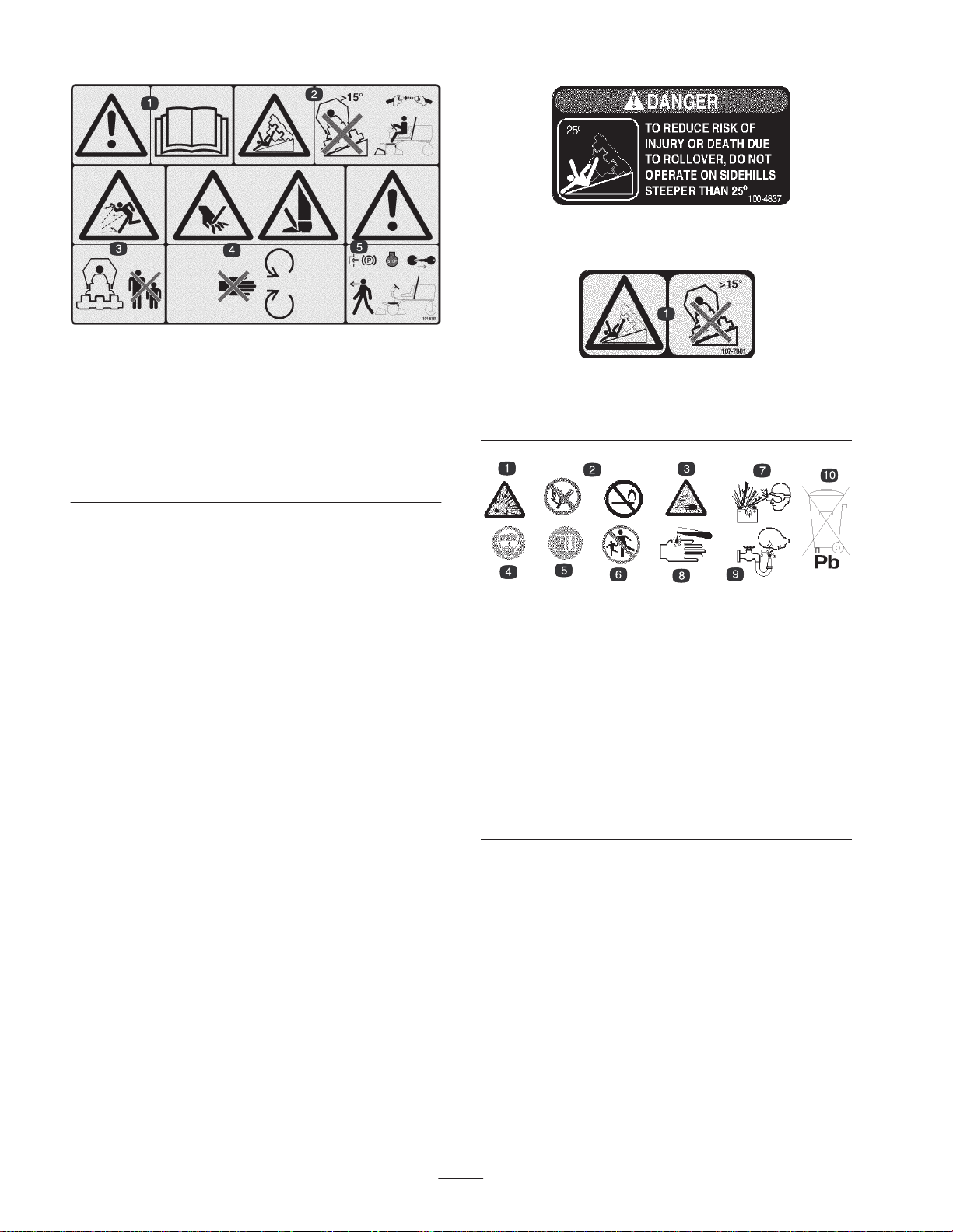
104-5181 for CE
1. Warning—read the
2. Tipping hazard—do not drive on slopes greater than 15
degrees and always wear the seat belt with ROPS.
3. Thrown object hazard—keep bystanders a safe distance from
the machine.
4. Cutting hazard of hand or foot—stay away from moving parts.
5. Warning—lock the parking brake, stop the engine, and remove
the ignition key before leaving the machine.
Operator’s Manual.
100-4837
107-7801 for CE
1. Tipping hazard—do not drive on slopes greater than 15
degrees.
Battery Symbols
Some or all of these symbols are on your battery.
1. Explosion hazard
2. No fire, open flames, or
smoking.
3. Caustic liquid/chemical
burn hazard
4. Wear eye protection
5. Read the
Manual.
6. Keep bystanders a safe
distance from the battery.
Operator’s
7. Wear eye protection;
explosive gases can
cause blindness and
other injuries
8. Battery acid can cause
blindness or severe
burns.
9. Flush eyes immediately
with water and get
medical help fast.
10. Contains lead; do not
discard.
10
Page 11

Specifications
Note: Specifications and design subject to change without notice.
General Specifications
Kubota three cylinder, 4 cycle liquid cooled diesel engine. 21.5 hp @ 2500 rpm
Engine
Governed to 2650 rpm. 68.5 cu. in. (1124 cc) displacement. Heavy duty, 2-stage,
remote mounted air cleaner. High water temperature shutdown switch.
Cooling System
Electrical
Fuel Capacity 7.5 gallons.
Traction Drive
Hydraulic System Remote mounted, 3.5 gallon oil reservoir. 10 micron remote mounted spin on filter.
Ground Speed
Tires/Wheels
Frame
Steering Power steering.
Brakes
Radiator capacity is approximately 6 qts. of 50/50 mixture of ethylene glycol
anti–freeze. Remote mounted 1 qt. expansion tank.
12 volt Group 55, 450 cold cranking amps at 0F (–18C), 75 minute reserve
capacity at 80F (27C). 40 amp alternator with regulator/rectifier. Seat switch,
PTO, parking brake and traction interlock switches.
High torque hydraulic wheel motors. 3–wheel drive. Oil cooler and shuttle valve
provide positive closed–loop cooling.
Infinitely variable speed selection in forward and reverse
Mowing speed: 0–6 mph (adjustable)
Transport speed: 0–9 mph
Reverse speed: 0–3.5 mph
Front tires are 20 x 12–10 tubeless tires and rear tires are 20 x 10–10 tubeless. All
have 4–ply rating with demountable rims. Recommended tire pressure: 14–18 psi
front and rear tires.
Tricycle vehicle with 3–wheel traction drive and rear wheel steering. Frame consists
of formed steel, welded steel and steel tubing components.
Service braking accomplished through dynamic characteristics of Hydrostat.
Parking or emergency brake is actuated by ratchet hand lever on the operator’s
right hand side.
Foot operated forward and reverse traction pedals and Mow/Transport slide. Hand
Controls
Gauges & Protective
Systems
Seat Optional standard or deluxe seats.
Cutting Unit Lift Hydraulic lift with automatic reel shut off.
operated throttle, ignition switch, reel engagement switch, reel unit lift and shift
lever, parking brake and seat adjustment. Shift lever only on Model 03201.
Hour meter. 4 light warning cluster gauge: oil pressure, water temperature, amps,
glow plug and side hill angle indicator.
Optional Equipment
Standard Seat Model No. 03224
11
Page 12

Setup
Note: Determine the left and right sides of the machine from the normal operating position.
Loose Parts Chart
Note: Use this chart as a checklist to ensure all parts necessary for assembly have been shipped. If any of these parts are
missing, total setup cannot be completed.
Description
Wheel assembly 3 Mount to wheel hubs
Steering wheel
Jam nut
Cover
Screw
Hood lock bracket
Screw 1/4–20 x 1–1/2” lg.
Flat washer 1/4–20
Lock nut 1/4–20
Exhaust guard
Self tapping screw
Hose clamp 1 Secure vent hose to vent tube of ROPS
Lift arms
Pivot rod
Capscrews 5/16–18 x 7/8” lg.
Thrust washers
Lynch pin
Qty. Use
1
1
1
1
1
1
1
1
1
4
2
2
2
2
2
Mount to steering shaft
Mount to hood for European Compliance
Mount to machine for European Compliance
Install pivot rods to lift arms
(supplied with Lift Arm Kit)
Mount cutting units to lift arms
(supplied with Lift Arm Kit)
Key 2
Inclinometer 1 Use for site survey before operating machine
EEC Decal
EEC Certificate
Operator’s manual 2 Read before operating the machine.
Engine operator’s manual 1 Read before operating the machine.
Parts catalog 1
Operator video 1 View before operating the machine
Pre–delivery check list 1
Registration cards 2 Fill out and return to Toro.
Note: Specifications and design subject to change without notice.
4
Affix to machine for European Compliance
2
12
Page 13
Install Wheels
1. Mount a wheel assembly onto each wheel hub (valve
stem outward).
Important Rear tire has a narrower rim than front tires.
2. Install lug nuts and torque to 45–65 ft–Ib.
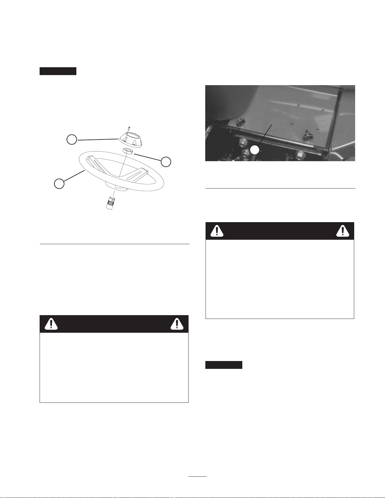
Install Steering Wheel
1. Slide steering wheel onto steering shaft.
3
2
1
Figure 1
1. Steering wheel
2. Jam nut
3. Cap
3. If Battery is not filled with electrolyte or activated, bulk
electrolyte with 1.260 specific gravity must be
purchased from a local battery supply outlet and added
to battery.
4. Remove filler caps from battery and slowly fill each
cell until electrolyte is just above the plates.
1
Figure 2
1. Battery cover
5. Replace filler caps and connect a 3 to 4 amp battery
charger to the battery posts. Charge the battery at a rate
of 3 to 4 amperes for 4 to 8 hours.
Caution
2. Secure steering wheel to shaft with jam nut and tighten
it to 25 ft-lb.
3. Install cap to steering wheel with screw.
Activate, Charge and Connect
Battery
Warning
CALIFORNIA
Proposition 65 Warning
Battery posts, terminals, and related accessories
contain lead and lead compounds, chemicals
known to the State of California to cause cancer
and reproductive harm. Wash hands after
handling.
1. Open hood.
2. Remove battery cover.
Wear safety goggles and rubber gloves when
working with electrolyte. Charge the battery in a
well ventilated place so gasses produced while
charging can dissipate. Since the gases are
explosive, keep open flames and electrical spark
away from the battery; do not smoke. Nausea may
result if the gases are inhaled. Unplug charger
from electrical outlet before connecting to or
disconnecting charger leads from battery posts.
6. When battery is charged, disconnect charger from
electrical outlet and battery posts.
7. Remove filler caps. Slowly add electrolyte to each cell
until level is up to fill ring. Install filler caps.
Important Do not overfill battery. Electrolyte will
overflow onto other parts of the machine and severe
corrosion and deterioration will result.
8. Install the positive cable (red) to the positive (+)
terminal and the negative cable (black) to the negative
(—) terminal of the battery and secure with capscrews
and nuts. Make sure positive (+) terminal is all the way
onto post and cable is positioned snug to battery. Cable
13
Page 14
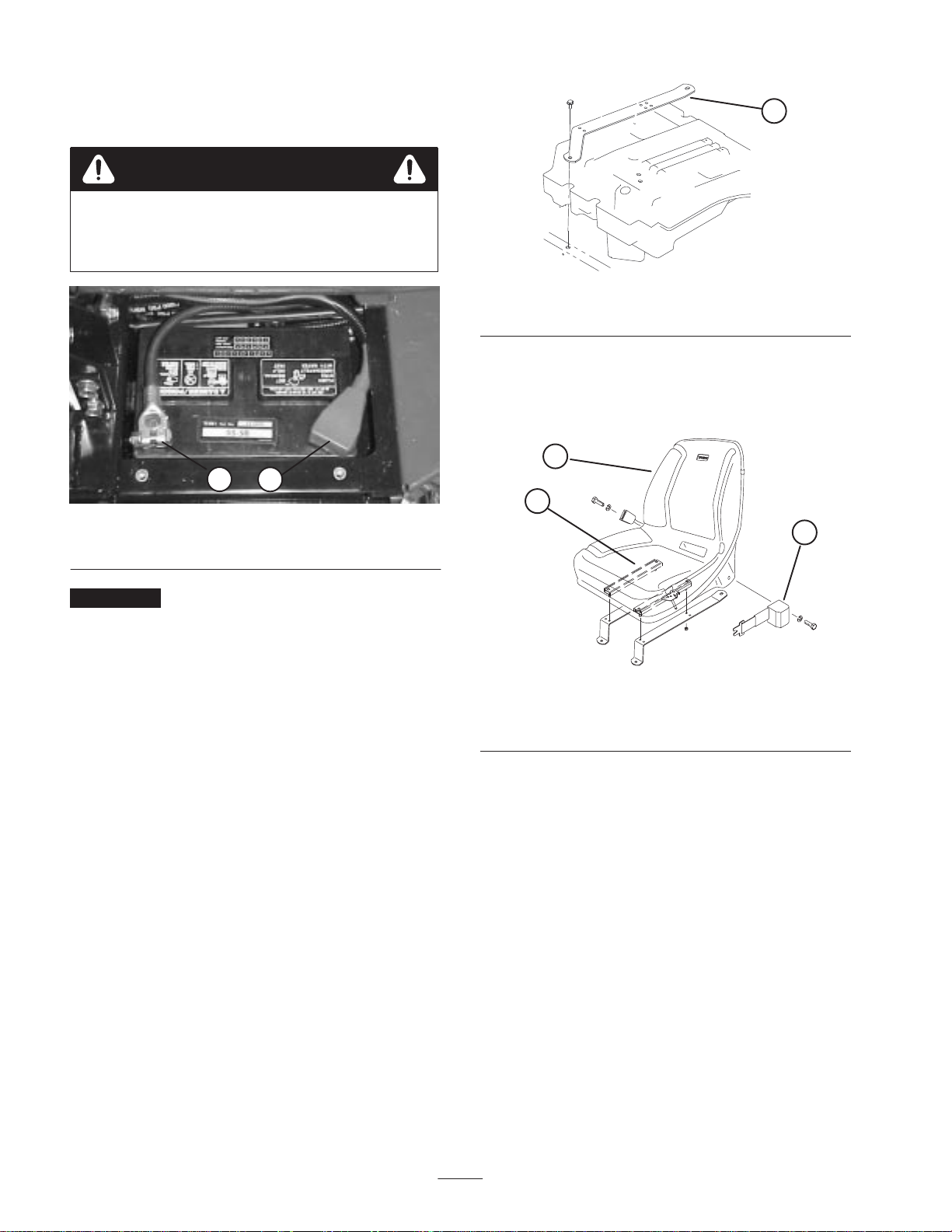
must not contact battery cover. Slide the rubber boot
over the positive terminal to prevent possible short–out
from occurring.
Warning
• Connecting cables to the wrong post could
damage the electrical system and result in
personal injury.
2
1. Positive (+) battery cable 2. Negative (–) battery cable
1
Figure 3
1
Figure 4
1. Seat mounting strap (2)
3. Install seat belt to holes on each side of seat with (2)
bolts and lockwashers (standard seat) or (2) bolts and
locknuts (deluxe seat). All mounting fasteners supplied
with seat kit loose parts.
1
2
3
Important If battery is ever removed, make sure
battery clamp bolts are reinstalled with bolt heads
positioned on bottom side and nuts on top side. If clamp
bolts are reversed, they may interfere with hard lines when
shifting cutting units.
9. Coat both battery connections with Grafo 112X (skin
over) grease, Toro Part No. 505–47, petroleum jelly or
light grease to prevent corrosion and slide rubber boot
over positive terminal.
10.Install battery cover.
Install Seat
The Reelmaster 3100 is shipped without the seat assembly.
Deluxe Seat Kit, Model 03225 or Standard Seat Kit, Model
03224, must be installed as follows:
1. Remove capscrews securing seat mounting straps to
traction unit frame (Fig. 4).
2. Secure seat mounting straps to seat adjusters with (4)
flange nuts (standard seat) or (4) capscrews, flat
washers and flange nuts (deluxe seat). Mounting
fasteners supplied with seat kit loose parts.
Figure 5
1. Standard seat
2. Seat adjusters
4. Position seat and seat straps on frame aligning
mounting holes.
5. Route seat switch wire under right hand seat strap and
connect to appropriate seat switch connector on harness.
6. On deluxe seat only, route unused seat switch connector
back under seat strap and secure both wires to rear most
hole in seat strap (Fig. 6) with a cable tie (cable tie
supplied with seat kit).
3. Seat belt
14
Page 15
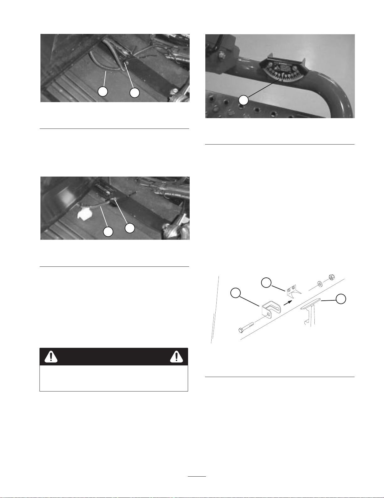
1
Figure 6
1. Seat switch wire 2. Cable tie
7. On standard seat only, slide seat all the way forward,
pull wire to the right so unused connector is positioned
as shown in figure 7 and secure seat switch wire to rear
most hole in seat strap with a cable tie (cable tie
supplied with seat kit).
2
1
Figure 8
1. Angle indicator
3. If inclinometer does not read zero degrees, move the
machine to a location where a zero degree reading is
obtained. The angle indicator, mounted on machine,
should now read zero degrees as well.
4. If angle indicator does not read zero degrees, loosen the
two screws and nuts securing angle indicator to
mounting bracket, adjust indicator to obtain a zero
degree reading and tighten capscrews.
1
Figure 7
1. Seat switch wire 2. Cable tie
8. Mount seat straps to frame with fasteners previously
removed.
9. Slide seat completely forward and backward to ensure
proper operation and that seat switch wires and
connectors are not pinched or do not contact any
moving parts.
2
Check Angle Indicator
Danger
To reduce risk of injury or death due to rollover do
not operate on side hills steeper than 25.
1. Park machine on a flat, level surface.
2. Verify that the machine is level by placing a hand held
inclinometer (supplied with machine) on the frame
cross rail, by the tool box. The inclinometer should read
zero degrees, when viewed from the operator’s position.
Install Hood Latch
(European Compliance)
1. Unhook hood latch from bracket.
2. Slide hood lock bracket onto latch.
2
3
Figure 9
1. Hood latch
2. Hood latch bracket
3. Re–hook latch onto bracket.
4. Insert 1/4–20 x 1–1/2” lg. capscrew thru hood lock
bracket and secure with a capscrew, flat washer and
locknut.
3. Hood lock bracket
1
15
Page 16
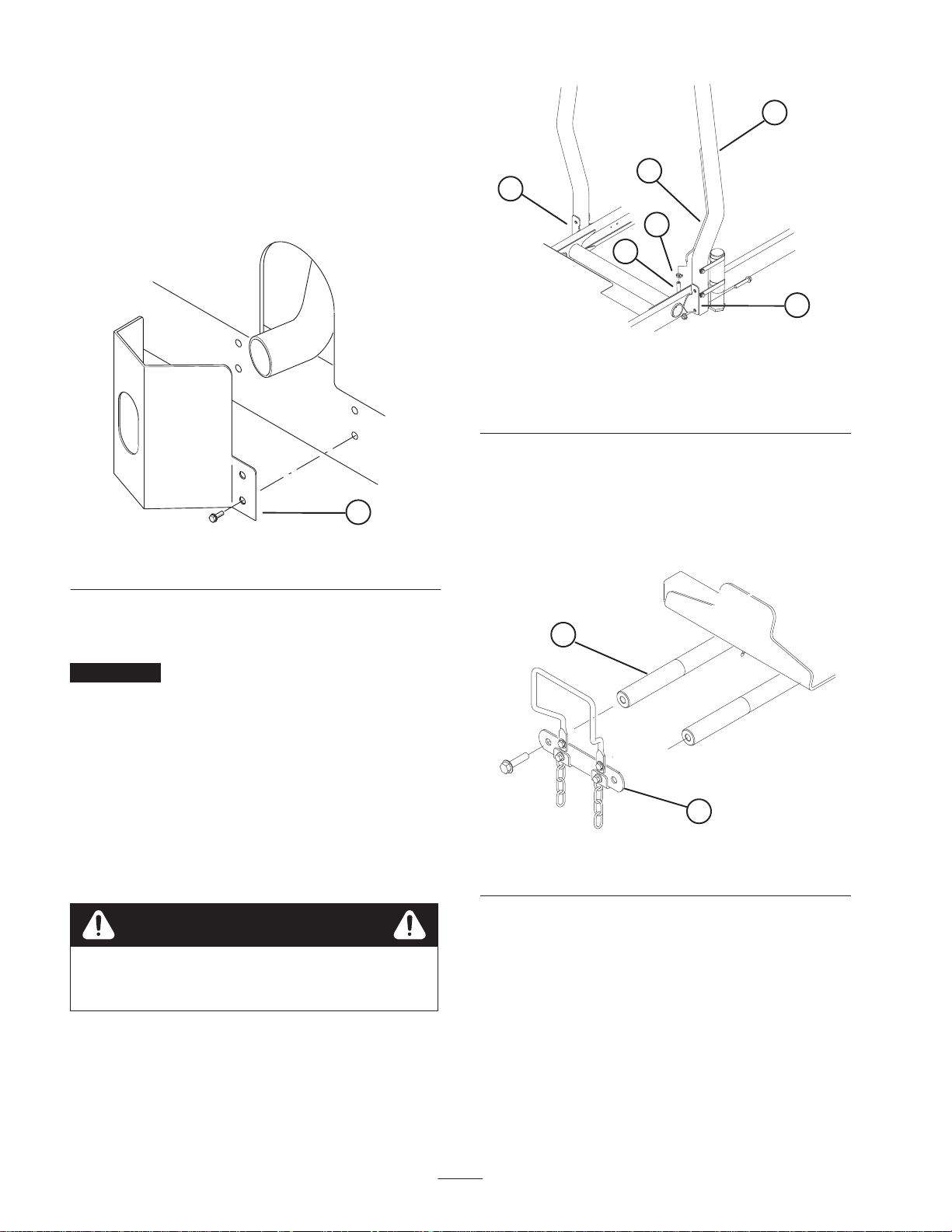
Install Exhaust Guard
(European Compliance)
1
1. Position exhaust guard around muffler while aligning
mounting holes with holes in frame.
2. Secure exhaust guard to frame with (4) self tapping
screws.
1
Figure 10
1. Exhaust guard
3
2
5
4
2
Figure 11
1. ROPS
2. Mounting bracket
3. Vent tube
4. Fuel line vent tube hose
5. Hose clamp
Install Front Lift Arms
1. Remove (2) capscrews securing lift arm pivot shaft link
to lift arm pivot shafts. Remove and retain pivot shaft
link and capscrews (Fig. 12).
Install ROPS
Important Never weld or modify ROPS. Replace a
damaged ROPS, do not repair or revise. Any alteration of
ROPS must be approved by manufacturer.
1. Lower ROPS frame onto traction unit mounting
brackets, aligning mounting holes. Vent tube, secured to
ROPS, must be positioned on left side of machine.
2. Secure each side of roll bar to mounting brackets with
(2) flange head capscrews and locknuts (Fig. 11).
Torque fasteners to 60 ft–lbs.
3. Secure fuel line vent hose to vent tube on ROPS with
hose clamp.
Caution
Fuel line vent hose must be connected to vent tube
prior to starting engine or fuel will flow from hose.
2
1
Figure 12
1. Lift arm pivot shaft link 2. Lift arm pivot shaft
2. Insert a pivot rod into each (R.H. & L.H.) lift arm and
align mounting holes (Fig. 13).
16
Page 17

1
2
Figure 13
1. Lift arm 2. Pivot rod
3. Secure pivot rods to lift arms with a 5/16 – 18 x 7/8” lg.
capscrew.
1
1. Lift cylinder
2. Hoses
2
3
Figure 15
3. Clearance here
4. Insert R.H. & L.H. lift arms onto lift arm pivot shafts.
Secure with lift arm pivot shaft link and capscrews
previously removed. Torque capscrews to 70 ft–lbs.
5. Remove rear retaining rings securing mounting pins to
each end of lift cylinder.
3
1
4
6
2
4
5
Figure 14
1. Lift arm (R.H.)
2. Lift arm (L.H.)
3. Retaining ring
4. Mounting pin
5. Lift cylinder
6. Spacer (2)
7. Secure left end of lift cylinder to left lift arm with pin.
Secure with retaining ring.
Note: With lift arms fully raised, hoses should be routed as
shown in figure 18 and clear lift arm by .04–.12”.
Mount Carrier Frames To
Cutting Units
1. Remove cutting units from cartons. Adjust per Cutting
Unit Operator’s Manual.
2. Position a front carrier frame (Fig. 16) onto each front
cutting unit. Align mounting holes with mounting links
as shown in figure 18.
1
6. Secure right end of lift cylinder to right lift arm with pin
and (2) spacers. Secure with retaining ring.
Figure 16
1. Front carrier frame
17
Page 18

3. Position rear carrier frame (Fig. 17) onto rear cutting
unit, aligning mounting holes with mounting links as
shown in figure 18.
Note: On rear cutting unit, thrust washer to be positioned
between rear of carrier frame and lynch pin.
1
Figure 17
1. Rear carrier frame
4. Secure each mounting link to carrier frame with a
3/8–16 x 2–1/4” lg capscrew, (2) flatwashers and a
locknut, as shown in figure 18. Position a washer on
each side of link when mounting. Torque to 31 ft–lb.
1
2
3
Figure 19
1. Thrust washer
2. Carrier frame
3. Lynch pin
3. Grease all lift arm and carrier frame pivot points.
Important Make sure hoses are free of twists or
sharp bends and rear cutting unit hoses are routed as
shown in Fig. 20. Raise cutting units and shift them to
the left (Model 03201 only). Rear cutting unit hoses
must not contact traction cable bracket. Re–position
fittings and / or hoses, if required.
1
2
3
FRONT
Figure 18
1. Carrier frame
2. Mounting link
3. Plug
Mount Cutting Units
1. Slide a thrust washer onto each front lift arm pivot rod.
2. Slide cutting unit carrier frame onto pivot rod and
secure with a lynch pin (Fig. 19).
Figure 20
4. Route a tipper chain up thru slot in end of each carrier
frame. Secure tipper chain to top of carrier frame with a
capscrew, washer and locknut (Fig. 21).
18
Page 19

1
Figure 21
1. Tipper chain
Mount Cutting Unit Drive
Motors
1. Spider coupling
2. Reel motor
1
Figure 23
3. O–ring
3
2
1. Position cutting units in front of lift arm pivot rods.
2. Remove weights and gasket (Fig. 22) from inside end of
right hand cutting unit. Remove plug from bearing
housing on outside end of right hand cutting unit and
install weights and gasket. Locate spider coupling
(Fig. 23) shipped in bearing housing.
1
2
Figure 22
1. Weights 2. Gasket
3. Remove shipping plug from bearing housings on
remaining cutting units (Fig. 18).
Adjust Lift Arms
1. Start engine, raise lift arms and check to make sure
clearance between each lift arm and floor plate bracket
is .18” – .32” (Fig. 24). If clearance is not in this range,
back off stop bolts (Fig. 26) and adjust cylinder to attain
clearance. To adjust cylinder, back off the jam nut on
the cylinder (Fig. 25), remove pin from rod end and
rotate clevis. Install pin and check clearance. Repeat
procedure if required. Tighten clevis jam nut.
2
3
1
Figure 24
1. Lift arm
2. Floor plate bracket
3. Clearance
4. Insert O–ring (supplied with cutting unit) on flange of
drive motor.
5. Mount the motor and the spider coupling to the drive
end of the cutting unit and secure with two capscrews
provided with cutting unit.
19
Page 20

2
1
2
1
Figure 25
1. Front cylinder 2. Jam nut
1
3
2
Figure 26
1. Stop bolt
2. Lift arm
3. Clearance
Note: If rear lift arm “clunks” during transport, clearance
can be reduced.
Figure 27
1. Wear bar 2. Bumper strap
1
2
Figure 28
1. Rear cylinder 2. Adjusting nut
Important Lack of clearance at front stops or rear
wear bar could damage lift arms.
2. Check to make sure clearance between each lift arm and
stop bolt is .005” – .040” (Fig. 26). If clearance is not in
this range, adjust stop bolts to attain clearance.
3. Start engine, raise lift arms and check to make sure
clearance between wear strap on top of rear cutting unit
wear bar and bumper strap is .020” – .100” (Fig. 27). If
clearance is not in this range, adjust rear cylinder to
attain clearance. To adjust cylinder, lower the cutting
units and back off the jam nut on the cylinder (Fig. 28).
Grasp cylinder rod close to the nut with a pliers and rag
and rotate the rod. Raise the cutting units and check
clearance. Repeat procedure if required. Tighten clevis
jam nut.
20
Page 21

Before Operating
Note: Determine the left and right sides of the machine
from the normal operating position.
Check Crankcase Oil
The engine is shipped with oil in the crankcase; however,
level of oil must be checked before and after the engine is
first started.
Important Check level of oil every 5 operating hours
or daily. Change oil after every 50 hours of operation.
Fill Fuel Tank
The engine runs on No. 2 diesel fuel.
Fuel tank capacity is approximately 7.5 gallons.
1. Clean area around fuel tank cap.
Crankcase capacity is approximately 4 qts. (2.8 l) with
filter.
1. Position machine on a level surface.
2. Remove dipstick and wipe it with a clean rag. Push
dipstick down into dipstick tube and make sure it is
seated fully. Pull dipstick out and check level of oil. If
oil level is low, add enough oil to raise level to FULL
mark on dipstick.
1
Figure 29
1. Dipstick
1
Figure 31
1. Fuel tank cap 2.
2. Remove fuel tank cap.
Danger
Under certain conditions, diesel fuel and fuel
vapors are highly flammable and explosive. A fire
or explosion from fuel can burn you and others
and can cause property damage.
1
Figure 30
1. Oil fill cap
3. If oil level is low, remove oil fill cap and gradually add
small quantities of oil, checking level frequently, until
level reaches FULL mark on dipstick.
4. The engine uses any high–quality 10W30 detergent oil
having the American Petroleum Institute – API –
“service classification” CD, CE, CF CF–4 or CG–4.
5. Install oil fill cap and close hood.
• Use a funnel and fill the fuel tank outdoors, in
an open area, when the engine is off and is cold.
Wipe up any fuel that spills.
• Do not fill the fuel tank completely full. Add fuel
to the fuel tank until the level is 1 in. (25 mm)
below the bottom of the filler neck. This empty
space in the tank allows the fuel to expand.
• Never smoke when handling fuel, and stay away
from an open flame or where fuel fumes may be
ignited by a spark.
• Store fuel in a clean, safety-approved container
and keep the cap in place.
3. Fill tank to bottom of filler neck. DO NOT
OVERFILL. Then install cap.
4. Wipe up any fuel that may have spilled to prevent a fire
hazard.
21
Page 22

Check Cooling System
4. Install expansion tank cap.
Clean debris off radiator and oil cooler daily (Fig. 32),
hourly if conditions are extremely dusty and dirty; refer to
Cleaning Radiator.
1. The cooling system is filled with a 50/50 solution of
water and permanent ethylene glycol anti–freeze. Check
level of coolant at beginning of each day before starting
the engine. Capacity of cooling system is approximately
6 quarts.
Caution
• If engine has been running, pressurized hot
coolant can escape when radiator cap is
removed and cause burns.
2
3
Check Hydraulic System Fluid
The hydraulic system driving the reels is designed to
operate on anti–wear hydraulic fluid. The machines
reservoir is filled at the factory with approximately 3.5
gallons of high quality hydraulic fluid. Check level of
hydraulic fluid before engine is first started and daily
thereafter. Appropriate hydraulic fluids are listed below.
The following list is not assumed to be all–inclusive.
Hydraulic fluids produced by other manufacturers may be
used if they can cross reference to find an equivalent to the
products listed. Toro will not assume responsibility for
damage caused by improper substitutions, so use only
products from reputable manufacturers who will stand
behind their recommendation.
Important Use only types of hydraulic fluids
specified. Other fluids could cause system damage.
Group 1 Hydraulic Fluid (Moderate climate– average
duty)
Note: The fluids within this group are interchangeable.
ISO VG 46/68 multi-viscosity anti-wear
hydraulic fluid
1
Figure 32
1. Access panel
2. Radiator
2. Check level of coolant in expansion tank. With a cold
engine, coolant level should be midway (approx)
between the marks on side of tank.
1
Figure 33
1. Expansion tank
3. Oil cooler
Mobil DTE 15M
Amoco Rykon Premium ISO 46
Castrol AWH 46
Conoco Hydroclear AW MV46
Gulf Harmony HVI 46 AW
Kendall Hyken Golden MV SAE 5W-20
Pennzbell AWX MV46
Phillips Magnus A KV 5W-20
Shell Tellus T 46
Sunoco Sun Hyd. Oil 2105
Texaco Rando HDZ 46
Universal Tractor Hydraulic Fluid
Mobil Mobil Fluid 424
Amoco 1000 Fluid
Chevron Tractor Hydraulic Fluid
Conoco Power-Tran 3
Exxon Torque Fluid
Pennzoil Hydra–Tranz
Shell Donax TD
Texaco TDH
3. If coolant level is low, remove expansion tank cap and
replenish the system. DO NOT OVERFILL.
22
Page 23

Group 2 Hydraulic Fluid (Hot Climate– Heavy Duty)
Note: The fluids within this group are interchangeable.
ISO VG 68 anti-wear hydraulic fluid
Note: A red dye additive for the hydraulic system fluid is
available in 2/3 oz. bottles. One bottle is sufficient for 4–6
gal. of hydraulic fluid. Order Part No. 44–2500 from your
Authorized Toro Distributor.
Mobil DTE 26
Amoco Rykon AW No. 68
Castrol AWS 68
Chevron Hydraulic Oil AW ISO 68
Conoco Hydroclear AW 68
Exxon Nuto H 68
Gulf Harmony 68AW
Kendall Four Seasons AW 68
Marathon ISO 68
Pennzbell AW Hydraulic Oil 68
Phillips Magnus A ISO 68
Shell Tellus 68
76 Lubricants AW 68
Sunoco SunVis 868
Texaco Rando HD 68
Important Group 1 fluids are recommended for use at
typical ambient temperatures of 32F (0C) to 105F
(41C). The ISO Type 46/68 fluid has been found to offer
optimal performance in a wide range of temperature
conditions for the average user. The Universal Tractor
Fluids offer similar performance for those who prefer them,
with perhaps some slight loss of efficiency at high ambient
temperatures compared to the Type 46/68 fluids.
Group 2 fluids are recommended for heavy-duty use in hot
climates where ambient temperatures range from about
70F (20C) to 120F (49C). Use at lower ambient
temperatures may result in hard starting, increased engine
laboring while cold, sluggish or non-operating spool valves
while cold and high filter back-pressure due to the higher
viscosity of these fluids.
Note: When changing from one type of hydraulic fluid to
another, be certain to remove all the old fluid from the
system, as some fluids are incompatible with others.
1
Figure 34
1. Hydraulic tank cap
1. Position machine on a level surface, lower the cutting
units and stop the engine.
2. Clean area around filler neck and cap of hydraulic tank.
Remove cap from filler neck.
3. Remove dipstick from filler neck and wipe it with a
clean rag. Insert dipstick into filler neck; then remove it
and check level of fluid. Fluid level should be within
1/4 inch of mark on dipstick.
4. If level is low, add appropriate fluid to raise level to full
mark.
5. Install dipstick and cap onto filler neck.
Check Tire Pressure
The tires are over–inflated for shipping. Therefore, release
some of the air to reduce the pressure. Correct air pressure
in tires is 14 –18 psi.
Important Maintain recommended pressure in all tires
to assure a good quality–of–cut and proper machine
performance.
Group 3 Hydraulic Fluid (Biodegradable)
ISO VG 32/46 anti-wear hydraulic fluid
Mobil EAL 224H
Note: This biodegradable hydraulic fluid is not compatible
with the fluids in Group 1 and 2.
Note: When changing from standard fluid to the
biodegradable type, be certain to follow approved flushing
procedures as published by Mobil. Contact your local Toro
Distributor for details.
Important Use only types of hydraulic fluids
specified. Other fluids could cause system damage.
Danger
Low tire pressure decreases the machine’s sidehill
stability. Do not under inflate tires. This could
cause a rollover, which may result in personal
injury or death.
23
Page 24

Check Reel To Bedknife
Contact
Each day before operating, check reel to bedknife contact,
regardless if quality of cut had previously been acceptable.
There must be light contact across the full length of the reel
and bedknife (refer to Adjusting Reel to Bedknife in
Cutting Unit Operator’s Manual).
Mow/Transport Slide
Using your heel, move slide to the left to transport and to
the right to mow. The cutting units will only operate in
the mow position.
Note: Mow speed is set at the factory to 6 mph. It can be
increased or decreased by adjusting the speed stop screw
(Fig. 36)
Check Torque Of Wheel Nuts
Warning
Torque wheel nuts to 45-65 ft–lb after 1-4 hours of
operation and again after 10 hours of operation
and every 200 hours thereafter. Failure to maintain
proper torque could result in failure or loss of
wheel and may result in personal injury.
Controls
Note: Determine the left and right sides of the machine
from the normal operating position.
Traction Pedals
Depress traction forward pedal to move forward. Depress
traction reverse pedal to move backward or to assist in
stopping when moving forward. Also, allow pedal to move
or move it to neutral position to stop machine.
4
Tilt Steering Lever
Pull lever back to loosen to tilt the steering wheel to desired
position. Then push lever forward to tighten.
Angle Indicator
Indicates sidehill angle of the machine in degrees.
Indicator Slot
The slot in the operator’s platform indicates when the
cutting units are in the center position.
1
Figure 36
1. Speed stop screw
1. Forward traction pedal
2. Reverse traction pedal
3. Mow/transport pedal
5
Figure 35
4. Tilt steering wheel
5. Indicator slot
6. Angle indicator
Starter Switch
6
3
1
2
The starter switch, used to start, stop and preheat the
engine, has three positions: OFF, ON/PREHEAT and
START. Rotate key to ON/PREHEAT position until glow
plug indicator light goes out (approximately 7 seconds),
then rotate key to START position to engage starter motor.
Release key when engine starts. The key will move
automatically to the ON/RUN position. To shut engine off,
rotate key to OFF position. Remove key from switch to
prevent accidental starting.
Throttle
Moving throttle forward increases engine speed, rearward
decreases engine speed.
24
Page 25

Cutting Unit Shift Lever
Hour Meter
To lower cutting units to the ground, move lift lever
forward. Cutting units will not drop unless engine is
running and will not operate in raised position. To raise
cutting units, pull lift lever rearward to the RAISE position.
Model 03201 only– Move lever to the right or left to move
cutting units in same direction. This should only be done
when cutting units are raised or if they’re on the ground
and the machine is moving.
Danger
The machine is most stable on a side hill when the
cutting units are shifted uphill. Shifting cutting
units downhill decreases machine stability. This
could cause a rollover, which may result in
personal injury or death.
Note: Lever does not have to be held in forward position
while cutting units are lowered.
Cutting Unit Drive Switch
The switch has two positions: ENGAGE and
DlSENGAGE. Rocker switch operates a solenoid valve, on
valve bank, to drive cutting units.
7
8
4
6
3
5
2
1
Indicates the total hours of machine operation. The Hour
Meter starts to function whenever the key switch is ON.
Engine Coolant Temperature Warning
Light
Light glows if engine coolant temperature is high. If
traction unit is not stopped and coolant temperature rises
another 10 F., the engine will kill.
Oil Pressure Warning Light
Light glows if engine oil pressure drops below a safe level.
Alternator Light
The amp light should be off when engine is running. If it is
on, the charging system should be checked and repaired as
necessary.
Glow Plug Indicator
Indicator light will glow when glow plugs are operating.
Parking Brake
Whenever the engine is shut off, the parking brake must be
engaged to prevent accidental movement of the machine.
To engage the parking brake, pull up on lever. Engine will
stop if traction pedal is depressed with parking brake
engaged.
Lift Lever Lock
10
11
1. Throttle
2. Hour meter
3. Temperature light
4. Oil pressure light
5. Glow plug indicator
6. Alternator light
Figure 37
7. Cutting unit drive switch
8. Cutting unit shift lever
9. Ignition switch
10. Parking brake
11. Lift lever lock
Move lever rearward to prevent cutting units from
9
dropping.
Reel Speed Control
(Located under console cover) – To obtain the desired clip
rate (reel speed), rotate reel speed control knob to
appropriate setting for height–of–cut setting and mower
speed. Refer to Selecting Clip Rate section of Manual.
Backlap Control
(Located under console cover) – Rotate knob clockwise for
backlapping and counterclockwise for mowing. Do not
change knob position when reels are rotating.
25
Page 26

2
Figure 38
1. Reel speed control 2. Backlap control
1
Operation
Note: Determine the left and right sides of the machine
from the normal operating position.
Starting/Stopping Engine
Important The fuel system may have to be bled if
any of the following situations have occurred:
• Initial start up of a new engine.
• Engine has ceased running due to lack of fuel.
• Maintenance has been performed upon fuel
system components; i.e. filter replaced, etc.
Fuel Gauge
Registers amount of fuel in tank.
Seat Adjustments
Fore and Aft Adjustment — Move lever on side of seat
outward, slide seat to desired position and release lever to
lock seat into position.
Deluxe Seat Adjustments
Weight Adjustment — Push lever up or down to adjust to
operator’s weight. Lever up — light operator, lever in
middle position — medium weight operator or lever down
for heavy operator.
Inclining Backrest — Turn handle to adjust angle of
backrest.
• Refer to Bleeding Fuel System
1. Be sure parking brake is set and Reel Drive switch is in
DISENGAGE position.
2. Remove foot from traction pedal and make sure pedal is
in neutral position.
3. Move throttle lever to 1/2 throttle position.
4. Insert key into switch and rotate it to ON/PREHEAT
position until glow plug indicator light goes out
(approximately 7 seconds), then rotate key to START
position to engage starter motor. Release key when
engine starts. The key will move automatically to the
ON/RUN position.
Important To prevent overheating of the starter
motor, do not engage starter longer than 15 seconds.
After 10 seconds of continuous cranking, wait 60
seconds before engaging starter motor again.
5. When engine is started for the first time, or after
overhaul of the engine, operate the machine in forward
and reverse for one to two minutes. Also operate the lift
lever and reel drive switch to be sure of proper
operation of all parts.
Turn steering wheel to the left and right to check steering
response. Then shut engine off and check for oil leaks,
loose parts and any other noticeable malfunctions.
2
Figure 39
1. Fore and aft lever 2. Fuel gauge
Caution
• Shut engine off and wait for all moving parts to
stop before checking for oil leaks, loose parts or
1
26
other malfunctions.
6. To stop engine, move throttle control to IDLE position,
move reel drive switch to DISENGAGE and rotate
starter key to OFF. Remove key from switch to prevent
accidental starting.
Page 27

Bleeding Fuel System
1. Park the machine on a level surface. Make sure fuel
tank is at least half full.
2. Unlatch and raise hood.
3. Open the air bleed screw on the fuel injection pump
(Fig. 40).
Note: Normally, engine should start after above bleeding
procedures are followed. However, if engine does not start,
air may be trapped between injection pump and injectors;
refer to Bleeding Air From Injectors.
Check Operation Of Interlock
Switches
Caution
Figure 40
1. Fuel injection pump bleed
screw
Danger
Under certain conditions, diesel fuel and fuel
vapors are highly flammable and explosive. A fire
or explosion from fuel can burn you and others
and can cause property damage.
• Use a funnel and fill the fuel tank outdoors, in
an open area, when the engine is off and is cold.
Wipe up any fuel that spills.
• Do not fill the fuel tank completely full. Add fuel
to the fuel tank until the level is 1 in. (25 mm)
below the bottom of the filler neck. This empty
space in the tank allows the fuel to expand.
• Never smoke when handling fuel, and stay away
from an open flame or where fuel fumes may be
ignited by a spark.
• Store fuel in a clean, safety-approved container
and keep the cap in place.
1
If safety interlock switches are disconnected or
damaged the machine could operate unexpectedly
causing personal injury.
• Do not tamper with the interlock switches.
• Check the operation of the interlock switches
daily and replace any damaged switches before
operating the machine.
• Replace switches every two years regardless of
whether they are operating properly or not.
1. Make sure all bystanders are away from the area of
operation. Keep hands and feet away from cutting units.
2. With operator on seat, the engine must not start with
either reel switch engaged or traction pedal engaged.
Correct problem if not operating properly.
3. With operator on the seat, traction pedal in neutral,
parking brake off and reel switch in OFF position, the
engine should start. Lift off the seat and slowly depress
the traction pedal, the engine should stop in one to
three seconds. Correct problem if not operating
properly.
4. With operator on the seat, engine running, reel transport
slide in mow and reel switch in ON position, lower
cutting units. Reels should come on. Pull back on the
lift lever, the reels should stop when fully raised.
Correct problem if not operating properly.
Note: The machine is equipped with an interlock switch on
the parking brake. Engine will stop if traction pedal is
depressed with parking brake engaged.
Towing Traction Unit
4. Turn key in ignition switch to the ON position. Electric
fuel pump will begin operation, thereby forcing air out
around air bleed screw. Leave key in ON position until
solid stream of fuel flows out around screw. Tighten
screw and turn key to OFF.
In case of emergency, the Reelmaster can be towed for a
short distance. However, Toro does not recommend this as
a standard procedure.
27
Page 28

Important Do not tow the machine faster than 2–3 mph
because drive system may be damaged. If machine must be
moved a considerable distance, transport it on a truck or
trailer.
Operating Characteristics
Danger
1. Locate by–pass valve on pump and rotate it 90.
1
Figure 41
1. By–pass valve
2. Before starting engine, close by–pass valve by rotating
it 90. Do not start engine when valve is open.
The mower has a unique traction system that will
allow the machine to move forward on side hills,
even if the uphill wheel should come of the ground.
If this should happen, the operator or any
bystanders can be seriously injured or killed in a
rollover.
The slope angle at which the machine will tip is
dependent on many factors. Among these are
mowing conditions such as wet or undulating turf,
speed (especially in turns), position of the cutting
units (with Sidewinder) tire pressure and operator
experience.
At side hill angles of 20 degrees or less the risk of a
rollover is low. As the slope angle increases to a
Toro recommended maximum limit of 25 degrees
the risk of a rollover increases to a moderate level.
DO NOT EXCEED A 25 DEGREE SIDE HILL
SLOPE ANGLE BECAUSE THE RISK OF A
ROLLOVER AND SERIOUS INJURY OR
DEATH IS VERY HIGH.
To determine which hills or slopes may be safely
operated on, a site survey of the mowing area must
be done. When performing this site survey always
use common sense and take into consideration the
turf condition and the rollover risk. To determine
which hills or slopes may be safely operated on use
the inclinometer provided with each machine. To
perform a site survey, lay a 4’ two by four on the
slope surface and measure the angle of the slope.
The 2 by 4 will average the slope but will not take
into consideration dips or holes which can cause a
sudden change in sidehill angle. THE MAXIMUM
SIDE HILL ANGLE SHOULD NOT BE
GREATER THAN 25 DEGREES.
Additionally, the Reelmaster 3100–D is equipped
with an angle indicator mounted on the steering
tube. This indicates the sidehill angle the machine
is on and identifies the recommended maximum
limit of 25 degrees.
ALWAYS WEAR YOUR SEAT BELT.
Practice operating the Reelmaster and become thoroughly
familiar with it.
Start the engine and run it at half idle until it warms up.
Push the throttle lever all the way forward, lift the cutting
units, disengage the parking brake, press the forward
traction pedal and carefully drive off to an open area.
28
Page 29

Practice going both forward and in reverse, starting and
stopping the machine. To stop, take your foot off
traction pedal and let it return to neutral or press down on
the reverse pedal to stop. Going down a hill, you may need
to use the reverse pedal to stop.
When driving on slopes, drive slowly to maintain steering
control and avoid turns to prevent rollovers. In side hill
situations you should shift the sidewinder cutting units
to the up hill side to give you more stability. Conversely,
shifting the cutting units to the down hill side will give
you less stability. This should always be done before
going on a side hill.
When possible, mow up and down hills rather than across
them. Have the cutting units lowered when going down a
hill to maintain steering control. Do not attempt to turn on a
hill.
Practice driving around obstacles with the reels up and
down. Be careful when driving between narrow objects so
you don’t damage the machine or cutting units.
On the Sidewinder unit, get a feel for the reach of the
cutting units so you don’t hang them up or damage them in
any way.
Don’t shift the units from side to side, unless the cutting
units are down and the machine is moving, or the cutting
units are up in the transport position. Shifting the cutting
units when they are down and the machine is not moving
may cause turf damage.
The Reelmaster is a precision mowing machine, so always
drive slowly in rough areas.
If a person appears in or near the operating area, stop the
machine, and don’t start up again until the area is cleared.
The Reelmaster is a one–person machine. Never let anyone
else ride on the machine with you. This is extremely
dangerous and could result in serious injury.
Accidents can happen to anyone. The most common causes
are excessive speed, sudden turns, terrain (with the
Reelmaster 3100–D that’s knowing what slopes and hills
can be mowed safely), not stopping the engine before
leaving the operator’s seat, and drugs which impair your
alertness. Cold capsules or prescription drugs may cause
drowsiness, as can alcohol and other drugs. Stay alert and
stay safe. Failure to do so could result in serious injury.
the
When transporting the machine from one work area to
another, raise cutting units to the fully up position, move
Mow/Transport slide to the left to transport and place
throttle in FAST position. (The cutting units will not
operate in transport.)
Mowing Techniques
To begin cutting, engage the reels, then approach the
mowing area slowly. Once the front reels are over the
mowing area, lower the cutting units.
To achieve the professional straight line cut and striping
that is desirable for some applications, find a tree or other
object in the distance and drive straight toward it.
As soon as the front reels reach the edge of the mowing
area, lift the cutting units and perform a tear drop turn, to
quickly line you up for your next pass.
Mowing around bunkers ponds or other contours is easily
done with The Reelmaster 3100–D with Sidewinder. To use
the Sidewinder application, move the control lever left or
right, depending on your mowing application. The cutting
units can also be shifted to vary tire tracking.
The Reelmaster 3100–D cutting units can throw clippings
to the front or rear. Front throw should be used when
cutting off smaller amounts of grass; thus, leaving a better
after cut appearance. To throw clippings to the front, simply
close the rear shield on the cutting units.
Caution
• Shut engine off and wait for all moving parts to
stop before opening or closing cutting unit
shields
When cutting off larger amounts of grass, the shields shown
be positioned to just below horizontal. Do not open the
shields too far or excessive clippings can build up on the
frame, rear radiator screen and engine area.
The cutting units are also equipped with balance weights,
on the non–motor end, to give an even cut. Weights can be
added or removed if mismatch occurs on your turf.
The Sidewinder offers up to a maximum of 23 inches of
overhang, allowing you to trim closer to the edge of traps
and other obstacles, while at the same time keeping the
tractor tires as far away from the edge of traps or water
hazards as possible.
If an obstacle is in the way, shift the cutting units to easily
mow around it.
The use of protective equipment for eyes, ears, feet, and
head is recommended.
After Mowing
At the completion of mowing operation, thoroughly wash
the machine with a garden hose – without a nozzle – so
excessive water pressure will not cause contamination and
damage to seals and bearings. Make sure radiator and oil
cooler are kept free of dirt or grass clippings. After
cleaning, it is recommended the machine be inspected for
possible hydraulic fluid leaks, damage or wear to hydraulic
and mechanical components and the cutting units checked
for sharpness and proper reel to bedknife adjustment.
29
Page 30

IMPORTANT: After wash down, move the Sidewinder
mechanism (model 03201 only) from left to right several
times to remove water between bearing blocks and cross
tube.
Selecting Clip Rate
(Reel Speed)
To achieve a consistent, high quality of cut, and a uniform
after cut appearance, it is important that the reel speed be
matched to the height of cut.
Important If reel speed is too slow, clip marks may be
visible. If reel speed is too fast the cut may have a fuzzy
appearance.
Adjust the clip rate (reel speed) as follows:
1. Verify the height–of–cut setting on the cutting units.
Using the column of the chart, on page 30, listing either
5 or 8 blade reels, find the height of cut listing nearest
the actual height–of–cut setting. Look across the chart
to find the number corresponding to that height of cut.
Note: The higher the number, the higher the speed.
2. Turn the reel speed control knob to the number setting
determined in step 1.
1
5 BLADE REEL
REEL SPEED SELECTION CHART
5 MPH 6 MPHHEIGHT OF CUT
2–1/2 2.50 3 3
2–3/8 2.38 3 4
2–1/4 2.25 3 4
2–1/8 2.13 3 4
2 2.00 3 4
1–7/8 1.88 4 5
1–3/4 1.75 4 5
1–5/8 1.63 5 6
1–1/2 1.50 5 7
1–3/8 1.38 5 8
1–1/4 1.25 6 11
1–1/8 1.13 8 11*
1 1.00 11 11*
7/8 0.88 11* 11*
3/4 0.75 11* 11*
5/8 0.63 11* 11*
1/2 0.50 11* 11*
3/8 0.38 11* 11*
* This height–of–cut and/or mowing speed not recommended
for 5 blade reels.
8 BLADE REEL
REEL SPEED SELECTION CHART
Figure 42
1. Reel speed control
3. Operate the machine for several days, then examine the
cut to ensure satisfaction with the quality of cut. The
reel speed knob may be set one position on either side
of the position indicated on the chart to account for
differences in grass condition, grass length removed and
personal preference.
5 MPH 6 MPHHEIGHT OF CUT
2–1/2 2.50 3* 3*
2–3/8 2.38 3* 3*
2–1/4 2.25 3* 3*
2–1/8 2.13 3* 3*
2 2.00 3* 3*
1–7/8 1.88 3* 3*
1–3/4 1.75 3* 3*
1–5/8 1.63 3* 3*
1–1/2 1.50 3 4
1–3/8 1.38 3 4
1–1/4 1.25 4 4
1–1/8 1.13 4 5
1 1.00 5 6
7/8 0.88 5 7
3/4 0.75 7 11
5/8 0.63 11 11*
1/2 0.50 11 11*
3/8 0.38 11 11*
* This height–of–cut and/or mowing speed not recommended
for 8 blade reels.
Note: Positions 9 to 11 give the same reel speed.
30
Page 31

Standard Control Module
(SCM)
The Standard Control Module is a ”potted” electronic
device produced in a ”one size fits all” configuration. The
module uses solid state and mechanical components to
monitor and control standard electrical features required for
safe product operation.
The module monitors inputs including neutral, parking
brake, PTO, start, backlap, and high temperature. The
module energizes outputs including PTO, Starter, and ETR
(energize to run) solenoid.
The module is divided into inputs and outputs. Inputs and
outputs are identified by green LED indicators mounted on
the printed circuit board.
The start circuit input is energized by 12 VDC. All other
inputs are energized when the circuit is closed to ground.
Each input has a LED that is illuminated when the specific
circuit is energized. Use the input LED’s for switch and
input circuit troubleshooting.
Output circuits are energized by an appropriate set of input
conditions. The three outputs include PTO, ETR, and
START. Output LED’s monitor relay condition indicating
the presence of voltage at one of three specific output
terminals.
Output circuits do not determine output device integrity so
electrical troubleshooting includes output LED inspection
and conventional device and wire harness integrity testing.
Measure disconnected component impedance, impedance
through wire harness (disconnect at SCM), or by
temporarily ”test energizing” the specific component.
The SCM does not connect to an external computer or hand
held device, can not be re–programmed, and does not
record intermittent fault troubleshooting data.
The decal on the SCM only includes symbols. Three LED
output symbols are shown in the output box. All other
LED’s are inputs. The chart below identifies the symbols.
Backlap
Hi Temp
Inputs
Park Brake Off
Here are the logical troubleshooting steps for the SCM
device.
1. Determine the output fault you are trying to resolve
(PTO, START, or ETR).
2. Move key switch to ”ON” and ensure the red ”power”
LED is illuminated.
3. Move all input switches to ensure all LED’s change
state.
In Seat
PTO Switch
Neutral
PTO
Start
ETR
Start
Power
5. If specific output LED is illuminated without
appropriate output function, check output harness,
connections, and component. Repair as required.
6. If specific output LED is not illuminated, check both
fuses.
7. If specific output LED is not illuminated and inputs are
in appropriate condition, install new SCM and
determine if fault disappears.
Outputs
4. Position input devices at appropriate position to achieve
the appropriate output. Use the following logic chart to
determine the appropriate input condition.
31
Page 32

Each row (across) in the logic chart below identifies input and output requirements for each specific product function.
Product functions are listed in the left column. Symbols identify specific circuit condition including: energized to voltage,
closed to ground, and open to ground.
– Indicates a circuit closed to ground. – LED ON
O Indicates a circuit open to ground or de–energized – LED OFF
+ Indicates an energized circuit (clutch coil, solenoid, or start input) LED ON.
” ” A Blank indicates a circuit that is not involved with the logic.
To troubleshoot, turn on the key without starting the engine.
Identify the specific function that does not work and work
across the logic chart. Inspect the condition of each input
LED’s to ensure it matches the logic chart.
If the input LED’s are correct, check the output LED. If the
output LED is illuminated but the device is not energized,
measure available voltage at the output device, continuity
of the disconnected device, and potential voltage on the
ground circuit (floating ground). Repairs will vary
depending on your findings.
32
Page 33

Lubrication
The traction unit has grease fittings that must be lubricated
regularly with No. 2 General Purpose Lithium Base Grease.
If machine is operated under normal conditions, lubricate
bearings and bushings after every 50 hours of operation.
Bearings and bushings must be lubricated daily when
operating conditions are extremely dusty and dirty. Dusty
and dirty operating conditions could cause dirt to get into
the bearings and bushings, resulting in accelerated wear.
Lubricate bearings and bushings immediately after every
washing, regardless of the interval listed.
The traction unit bearings and bushings that must be
lubricated are: Rear cutting unit pivot (Fig. 43), Front
cutting unit pivot (Fig. 44), SideWinder cylinder ends (2)
(Model 03201 only) (Fig. 45), Steering pivot (Fig. 46),
Rear lift arm pivot and lift cylinder (2) (Fig. 47), Left front
lift arm pivot and lift cylinder (2) (Fig. 48), Right front lift
arm pivot and lift cylinder (2) (Fig. 49), Neutral adjust
mechanism (Fig. 50), Mow/Transport slide (Fig. 51), Belt
tension pivot (Fig. 52) Steering cylinder (Fig. 53).
Figure 44
Note: If desired, an additional grease fitting may be
installed in other end of steering cylinder. Tire must be
removed, fitting installed, greased, fitting removed and
plug installed (Fig. 54).
Important Do not lubricate Sidewinder (model 03201)
cross tube, bearing blocks are self lubricated.
Figure 43
(2)
Figure 45
33
Figure 46
Page 34

Figure 47
(2)
Figure 50
Figure 48
Figure 49
Figure 51
Figure 52
34
Page 35

Figure 53
Figure 54
(see note)
35
Page 36

Maintenance
Note: Determine the left and right sides of the machine from the normal operating position.
Recommended Maintenance Schedule
Maintenance Service
Interval
After first 10 hours
After first 50 hours
Every 50 hours
Every 100 hours
Every 200 hours
Every 400 hours
Maintenance Procedure
• Check Fan and Alternator Belt Tensions
• Change Hydraulic Filter
• Torque Wheel Lug Nuts
• Change Engine Oil Filter
• Check Engine RPM (idle and full throttle)
• Inspect Air Filter, Dust Cup, and Burp Valve
• Lubricate All Grease Fittings
• Change Engine Oil
• Check Battery Cable Connections
• Check Fan and Alternator Belt Tensions
• Check Battery Fluid Level
• Change Engine Oil Filter
• Check Traction Belt
• Change Air Filter
• Change Hydraulic Filter
• Torque Wheel Lug Nuts
• Change Hydraulic Fluid
• Change Fuel/Water Separator Filter
• Change Fuel Pre Filter
• Inspect Traction Cable Movement
• Inspect Spider Coupling for Wear
• Check Engine RPM (idle and full throttle)
Every 800 hours • Adjust valves
• Replace Moving Hoses
• Replace Safety Switches
Every 1000 hours
• Coolant System – Flush/Replace Fluid
• Fuel Tank – Drain/Flush
• Hydraulic Tank – Drain/Flush
36
Page 37

If you leave the key in the ignition switch, someone could accidently start the engine and
seriously injure you or other bystanders.
Remove the key from the ignition and disconnect the wire from the spark plug before you do any
maintenance. Set the wire aside so that it does not accidentally contact the spark plug.
Daily Maintenance Checklist
Duplicate this page for routine use.
For the week of:
Caution
Maintenance Check Item
Check Safety Interlock Operation
Check Brake Operation
Check Fuel Level
Check Engine Oil Level
Check Cooling System Fluid Level
Check Drain Water/Fuel Separator
Check Air Filter, Dust Cup & Burp Valve
Check Radiator & Screen for Debris
Check Unusual Engine Noises
Check Unusual Operating Noises
Check Hydraulic System Oil Level
Check Hydraulic Hoses for Damage
Check Fluid Leaks
Check Tire Pressure
Check Instrument Operation
Check Reel–to–Bedknife Adjustment
1
Mon. Tues. Wed. Thurs. Fri. Sat. Sun.
Check Height–of–Cut Adjustment
Lubricate All Grease Fittings
Touch–up Damaged Paint
1
= Check glow plug and injector nozzles, if hard starting, excess smoke or rough running is noted.
2
= Immediately after every washing, regardless of the interval listed.
Important Refer to your engine operator’s manual for additional maintenance procedures.
2
37
Page 38

Service Interval Chart
Hood Removal
Hood may be easily removed to ease maintenance
procedures in engine area of machine.
1. Unlatch and raise hood.
2. Remove cotter pin securing hood pivot to mounting
brackets.
3. Slide hood to right side, lift other side and pull out of
brackets.
4. Reverse procedure to reinstall hood.
1
Figure 55
1. Cotter pin
38
Page 39

General Air Cleaner
Maintenance
• Check air cleaner body for damage which could
possibly cause an air leak. Replace a damaged air
cleaner body.
• Service the air cleaner filter every 200 hours (more
frequently in extreme dusty or dirty conditions). Do not
over service air filter.
• Be sure cover is sealing around air cleaner body.
Servicing Air Cleaner
1. Release latches securing air cleaner cover to air cleaner
body. Separate cover from body. Clean inside of air
cleaner cover.
2
7. Insert new filter properly into air cleaner body. Make
sure filter is sealed properly by applying pressure to
outer rim of filter when installing. Do not press on
flexible center of filter.
1
Figure 57
1. Filter element
8. Reinstall cover and secure latches. Make sure cover is
positioned with TOP side up.
1
Figure 56
1. Air cleaner dust cup 2. Air cleaner latches
2. Gently slide filter out of air cleaner body to reduce the
amount of dust dislodged. Avoid knocking filter against
air cleaner body.
3. Inspect filter and discard if damaged. Do not wash or
reuse a damaged filter.
4. Blow compressed air from inside to the outside of dry
filter element. Do not exceed 100 psi to prevent damage
to the element.
5. Keep air hose nozzle at least 2” from filter and move
nozzle up and down while rotating the filter element.
Inspect for holes and tears by looking through the filter
toward a bright light.
6. Inspect new filter for shipping damage. Check sealing
end of filter. Do not install a damaged filter.
Engine Oil and Filter
Change oil and filter initially after the first 50 hours of
operation, thereafter change oil every 50 hours and filter
every 100 hours.
1. Remove either drain plug and let oil flow into drain
pan. When oil stops, install drain plug.
1
Figure 58
1. Engine oil drain plug 2.
39
Page 40

2. Remove oil filter. Apply a light coat of clean oil to the
new filter seal before screwing it on. DO NOT
OVER–TIGHTEN.
1
3. Lubricate gasket on filter canister with clean oil.
4. Install filter canister by hand until gasket contacts
mounting surface, then rotate an additional 1/2 turn.
1
Figure 59
1. Engine oil filter
3. Add oil to crankcase, refer to Check Engine Oil.
Fuel System
Fuel Tank
Drain and clean fuel tank every 2 years. Also, drain and
clean tank if fuel system becomes contaminated or if
machine is to be stored for an extended period. Use clean
fuel to flush out the tank.
Fuel Lines and Connections
Check lines and connections every 400 hours or yearly,
whichever comes first. Inspect for deterioration, damage, or
loose connections.
Water Separator
2
Figure 60
1. Water separator 2. Drain plug
Replacing Fuel Pre Filter
Replace the fuel pre filter, located on inside of frame rail
below water separator after every 400 operating hours or
yearly, whichever occurs first.
1. Remove screw securing filter to frame rail.
2. Clamp both fuel lines that connect to the fuel filter so
fuel cannot drain when lines are removed.
3. Loosen the hose clamps at both ends of the filter and
pull fuel lines off filter.
2
2
Drain water or other contaminants from water separator
(Fig. 60) daily.
1. Place a clean container under fuel filter.
2. Loosen drain plug on bottom of filter canister. Tighten
plug after draining.
Replace filter canister after every 400 hours of operation.
1. Clean area where filter canister mounts.
2. Remove filter canister and clean mounting surface.
1
Figure 61
1. Fuel pre filter 2. Hose clamp
40
Page 41

4. Slide hose clamps onto ends of fuel lines. Push fuel
lines onto fuel filter and secure them with hose clamps.
Be sure arrow on side of filter points toward the
injection pump.
Danger
Under certain conditions, diesel fuel and fuel
vapors are highly flammable and explosive. A fire
or explosion from fuel can burn you and others
and can cause property damage.
• Use a funnel and fill the fuel tank outdoors, in
an open area, when the engine is off and is cold.
Wipe up any fuel that spills.
• Do not fill the fuel tank completely full. Add fuel
to the fuel tank until the level is 1 in. (25 mm)
below the bottom of the filler neck. This empty
space in the tank allows the fuel to expand.
• Never smoke when handling fuel, and stay away
from an open flame or where fuel fumes may be
ignited by a spark.
• Store fuel in a clean, safety-approved container
and keep the cap in place.
5. Repeat steps on remaining nozzles.
Cleaning Engine Cooling
System
Remove debris from oil cooler and radiator daily, clean
more frequently in dirty conditions.
• Turn engine off and raise hood. Clean engine area
thoroughly of all debris.
• Remove access panel.
2
3
1
Bleeding Air From Injectors
Note: This procedure should be used only if fuel system
has been purged of air through normal priming procedures
and engine will not start; refer to Bleeding Fuel System.
1. Loosen the pipe connection to the No. 1 nozzle and
holder assembly.
1
Figure 62
1. Fuel injectors (3)
2. Move throttle to FAST position.
Figure 63
1. Access panel
2. Oil cooler
• Remove access panel. Unlatch oil cooler and pivot
rearward. Clean both sides of oil cooler and radiator
area thoroughly with water or compressed air. Pivot oil
cooler back into position.
Figure 64
• Install access panel and close hood.
3. Radiator
3. Turn key in key switch to START position and watch
fuel flow around connector. Turn key to OFF position
when solid flow is observed.
4. Tighten pipe connector securely.
41
Page 42

Servicing Engine Belts
Check condition and tension of all belts after first day of
operation and every 100 operating hours thereafter.
Alternator/fan Belt
1. Open hood.
2. Check tension by depressing belt midway between
alternator and crankshaft pulleys with 22 lb. of force.
Belt should deflect 7/16 in. If deflection is incorrect,
proceed to step 3. If correct, continue operation.
3. Loosen bolt securing brace to engine and bolt securing
alternator to brace.
4. Insert pry bar between alternator and engine and pry out
on alternator.
5. When proper tension is achieved, tighten alternator and
brace bolts to secure adjustment.
2
1
Figure 66
1. Hydrostat drive belt 2. Spring end
Adjusting Throttle
1. Position throttle lever rearward so it stops against
control panel slot.
2. Loosen the throttle cable connector on the lever arm at
the injection pump.
1
Figure 65
1. Alternator /fan belt
Hydrostat Drive Belt Replacement
1. Insert a nut driver or small piece of tubing onto end of
belt tensioning spring.
Warning
Use caution when de–tensioning spring as it is
under heavy load.
2. Push down and forward on spring end to unhook from
bracket and release tension on spring.
3. Replace belt.
4. Reverse procedure to tension spring.
1
Figure 67
1. Injection pump lever arm
3. Hold the injection pump lever arm against the low idle
stop and tighten the cable connector.
4. Loosen screws securing throttle control to control panel.
5. Push throttle control lever all the way forward.
6. Slide stop plate until it contacts throttle lever and
tighten screws securing throttle control to control panel.
7. If throttle does not stay in position during operation,
torque the lock nut, used to set the friction device on the
throttle lever, to 40 – 55 in. lb. The maximum force
required to operate the throttle lever should be 20 lb.
42
Page 43

Changing Hydraulic Fluid
Change hydraulic fluid after every 400 operating hours, in
normal conditions. If fluid becomes contaminated, contact
your local TORO distributor because the system must be
flushed. Contaminated fluid looks milky or black when
compared to clean oil.
1. Turn engine off and raise hood.
2. Disconnect hydraulic line or remove hydraulic filter and
let hydraulic fluid flow into drain pan. Reinstall line
when hydraulic fluid stops draining.
1
Figure 70
1. Hydraulic reservoir
Replacing Hydraulic Filter
1
Figure 68
1. Hydraulic line
1
Figure 69
1. Hydraulic filter
3. Fill reservoir with approximately 3.5 gallons of
hydraulic fluid. Refer to Checking Hydraulic Fluid.
The hydraulic system filter must be changed initially, after
the first 10 hours of operation, and thereafter every 200
hours of operation or yearly, whichever comes first. Use a
genuine Toro oil filter for replacement. The hydraulic oil
must be changed every 400 hours of operation or yearly,
whichever comes first.
Use the Toro replacement filter (Part No. 54–0110).
Important Use of any other filter may void the
warranty on some components.
1. Position machine on a level surface, lower the cutting
units, stop the engine, engage the parking brake and
remove key from ignition switch.
2. Pinch off hose to filter mounting plate.
3. Clean area around filter mounting area. Place drain pan
under filter and remove filter.
4. Lubricate new filter gasket and fill the filter with
hydraulic fluid.
5. Assure filter mounting area is clean. Screw filter on
until gasket contacts mounting plate. Then tighten filter
one–half turn.
6. Start engine and let run for about two minutes to purge
air from the system. Stop the engine and check for
leaks.
Important Use only hydraulic fluids specified. Other
fluids could cause system damage.
4. Install reservoir cap. Start engine and use all hydraulic
controls to distribute hydraulic fluid throughout the
system. Also check for leaks. Then stop the engine.
5. Check level of fluid and add enough to raise level to
FULL mark on dipstick. DO NOT OVER FILL.
Checking Hydraulic Lines And
Hoses
Daily, check hydraulic lines and hoses for leaks, kinked
lines, loose mounting supports, wear, loose fittings, weather
deterioration and chemical deterioration. Make all
necessary repairs before operating.
43
Page 44

Warning
Hydraulic fluid escaping under pressure can
penetrate skin and cause injury.
• Make sure all hydraulic fluid hoses and lines are
in good condition and all hydraulic connections
and fittings are tight before applying pressure to
the hydraulic system.
• Keep your body and hands away from pin hole
leaks or nozzles that eject high pressure
hydraulic fluid.
• Use cardboard or paper to find hydraulic leaks.
• Safely relieve all pressure in the hydraulic
system before performing any work on the
hydraulic system.
• Get immediate medical help if fluid is injected
into skin.
1
2
Figure 71
1. Traction adjustment cam 2. Locknut
4. Start engine and rotate cam hex in both directions to
determine mid position of neutral span.
Adjusting Traction Drive For
Neutral
If the machine “creeps” when the traction pedal is in the
neutral position, the traction cam must be adjusted.
1. Park the machine on a level surface and turn the engine
off.
2. Raise one front wheel and rear wheel off floor and place
support blocks under frame.
Warning
One front wheel and rear wheel must be raised off
the ground or the machine will move during
adjustment. Make sure machine is supported so it
will not accidentally fall injuring anyone under
machine.
3. Loosen locknut on traction adjustment cam.
Warning
5. Tighten locknut securing adjustment.
6. Stop the engine.
7. Remove support blocks and lower the machine to the
shop floor. Test drive the machine to make sure it does
not creep.
Adjusting Parking Brake
Check adjustment every 200 hours.
1. Loosen set screw securing knob to parking brake lever.
2. Rotate knob until a force of 30–40 lbs. is required to
actuate lever.
3. Tighten set screw after adjustment has been attained.
3
1
2
Engine must be running so final adjustment of the
traction adjustment cam can be performed. To
guard against possible personal injury, keep hands,
feet, face and other parts of the body away from
the muffler, other hot parts of the engine, and
other rotating parts.
1. Parking brake lever
2. Knob
44
Figure 72
3. Set screw
Page 45

Battery Care
Warning
CALIFORNIA
Proposition 65 Warning
Battery posts, terminals, and related accessories
contain lead and lead compounds, chemicals
known to the State of California to cause cancer
and reproductive harm. Wash hands after
handling.
1. Battery electrolyte level must be properly maintained
and the top of the battery kept clean. lf the machine is
stored in a location where temperatures are extremely
high, the battery will run down more rapidly than if the
machine is stored in a location where temperatures are
cool.
6. If corrosion occurs at terminals, disconnect cables,
negative (—) cable first and scrape clamps and
terminals separately. Reconnect cables, positive (+)
cable first and coat terminals with petroleum jelly.
7. Always disconnect battery cables, ground cable (—)
first, to prevent possible wiring damage from short outs
whenever working with the electrical system.
Battery Storage
If the machine will be stored more than 30 days, remove
the battery and charge it fully. Either store it on the shelf on
the machine. Leave the cables disconnected if stored on the
machine. Store the battery in a cool atmosphere to avoid
quick deterioration of the charge in the battery. To prevent
battery from freezing, make sure it is fully charged. The
specific gravity of a fully charged battery is 1.265 – 1.299.
Fuses
2. Check the electrolyte level every 25 operating hours or,
if machine is in storage, every 30 days.
3. Maintain cell level with distilled or demineralized
water. Do not fill cells above the bottom of the split ring
inside each cell. Install filler caps with vents pointing to
the rear (toward fuel tank).
Caution
Wear safety goggles and rubber gloves when
working with electrolyte. Charge the battery in a
well ventilated place so gasses produced while
charging can dissipate. Since the gases are
explosive, keep open flames and electrical spark
away from the battery; do not smoke. Nausea may
result if the gases are inhaled. Unplug charger
from electrical outlet before connecting to or
disconnecting charger leads from battery posts.
4. Keep top of battery clean by washing periodically with
a brush dipped in ammonia or bicarbonate of soda
solution. Flush the top surface with water after cleaning.
Do not remove the fill caps while cleaning.
5. Battery cables must be tight on terminals to provide
good electrical contact.
Warning
The fuses in machines electrical system are located under
console cover.
Backlapping
Danger
TO AVOID PERSONAL INJURY OR DEATH:
• Never place hands or feet in reel area while
engine is running.
• While backlapping, reels may stall and then
restart.
• Do not attempt to restart reels by hand or foot.
• Do not adjust reels while engine is running.
• If reel stalls, stop engine before attempting to
clear reel.
1. Position machine on a clean, level surface, lower the
cutting units, stop the engine, engage parking brake and
remove key from ignition switch.
2. Remove console cover to expose controls.
3. Rotate backlap knob to backlap position. Rotate reel
speed knob to position 1.
Note: Seat switch is bypassed when backlap knob is in
backlap position. Operator does not need to be in seat, but
parking brake must be engaged or engine will not run.
Connecting cables to the wrong post could result in
personal injury and/or damage to the electrical
system.
45
Page 46

Caution
Caution
Do not rotate backlap knob from mow to backlap
position while engine is running as damage to reels
may occur.
2
1
Figure 73
1. Backlap knob 2. Reel speed knob
4. Make initial reel to bedknife adjustments appropriate
for backlapping on all cutting units. Start engine and set
engine to low idle speed.
5. Engage reels by engaging PTO switch on control panel.
Be careful when lapping the reel because contact
with the reel or other moving parts can result in
personal injury.
7. To make an adjustment to the cutting units while
backlapping, disengage reels and turn engine OFF.
After adjustments have been completed, repeat steps
4–6.
8. When backlap operation is completed, stop the engine,
rotate backlap knob to MOW position, set reel speed
controls to desired mowing setting and wash all lapping
compound off cutting units.
Note: Additional instructions and procedures on
Backlapping are available in the TORO Sharpening Reel &
Rotary Mowers Manual Form No. 80–300SL.
Note: For a better cutting edge, run a file across the front
face of the bedknife when the lapping operation is
completed. This will remove any burrs or rough edges that
may have built up on the cutting edge.
6. Apply lapping compound with long handled brush.
46
Page 47

Electrical Schematic
47
Page 48

Hydraulic Schematic
PORT
LOWER
FORWARD
INTERNAL CASE DRAIN
FILTER
STRAINER
HYDROSTAT
OIL
GEAR PUMP
RPM
P1 P2
P3
ENGINE
100–150 psi
OIL
COOLER
P1 LV
CHG
ST
LC2
3000 psi
TRACTION WHEEL MOTORS
DUMP
VALVE
M6
FC1
LC1 LOGIC
TOP PORT
G1
BACKLAPPING
VALVE
MD1
UPPER
PORT
CONTROLLER
REEL SPEED
T1
VALVE
S1
3000 psi
RELIEF
R1
REEL
VALVE
ON–OFF
REEL
M4
M5
T2
D1
M1
M2
STEERING
VALVE
POWER
AUX
OUT
R
1000 psi
V1
STEERING
IN
G2
IN
OUT
L
D
PLG
MANIFOLD
CF
CR
A
B
C
SIDEWINDER
BLOCK
LEFT
R
F
RIGHT
REAR
48
Page 49

Storage
Traction Unit
• Thoroughly clean the traction unit, cutting units and the
engine.
• Check the tire pressure. Inflate all tires to 14–18 psi.
• Check all fasteners for looseness; tighten as necessary.
• Grease or oil all grease fittings and pivot points. Wipe
up any excess lubricant.
• Cover the entire length of the Sidewinder (Model
03201) cross tube with a light oil to prevent rust. After
storage, wipe off all oil.
• Lightly sand and use touch–up paint on painted areas
that are scratched, chipped, or rusted. Repair any dents
in the metal body.
• Service the battery and cables as follows:
Engine
• Drain the engine oil from the oil pan and replace the
drain plug.
• Remove and discard the oil filter. Install a new oil filter.
• Refill oil pan with approximately 4.0 quarts of
SAE10W-30 motor oil.
• Start the engine and run at idle speed for approximately
two minutes.
• Stop the engine.
• Thoroughly drain all fuel from the fuel tank, lines fuel
filter and water separator assembly.
• Flush the fuel tank with fresh, clean diesel fuel.
• Re–secure all fuel system fittings.
• Thoroughly clean and service the air cleaner assembly.
• Seal the air cleaner inlet and the exhaust outlet with
weatherproof tape.
• Remove the battery terminals from the battery posts.
• Clean the battery, terminals, and posts with a wire
brush and baking soda solution.
• Coat the cable terminals and battery posts with
Grafo 112X skin–over grease (Toro Part No.
505-47) or petroleum jelly to prevent corrosion.
• Slowly recharge the battery every 60 days for 24
hours to prevent lead sulfation of the battery.
• Check anti–freeze protection and add as needed for
expected minimum temperature in your area.
49
Page 50

50
Page 51

51
Page 52

The Toro General Commercial Products Warranty
A Two-Year Limited Warranty
Conditions and Products Covered
The Toro Company and its affiliate, Toro Warranty Company,
pursuant to an agreement between them, jointly warrant your Toro
Commercial Product (“Product”) to be free from defects in
materials or workmanship for two years or 1500 operational
hours*, whichever occurs first. Where a warrantable condition
exists, we will repair the Product at no cost to you including
diagnosis, labor, parts, and transportation. This warranty begins
on the date the Product is delivered to the original retail purchaser.
* Product equipped with hour meter
Instructions for Obtaining Warranty Service
You are responsible for notifying the Commercial Products
Distributor or Authorized Commercial Products Dealer from whom
you purchased the Product as soon as you believe a warrantable
condition exists.
If you need help locating a Commercial Products Distributor or
Authorized Dealer, or if you have questions regarding your
warranty rights or responsibilities, you may contact us at:
Toro Commercial Products Service Department
Toro Warranty Company
8111 Lyndale Avenue South
Bloomington, MN 55420-1196
952-888-8801 or 800-982-2740
E-mail: commercial.service@toro.com
Owner Responsibilities
As the Product owner, you are responsible for required maintenance and adjustments stated in your operator’s manual. Failure
to perform required maintenance and adjustments can be grounds
for disallowing a warranty claim.
Items and Conditions Not Covered
Not all product failures or malfunctions that occur during the
warranty period are defects in materials or workmanship. This
express warranty does not cover the following:
• Product failures which result from the use of non-Toro
replacement parts, or from installation and use of add-on,
modified, or unapproved accessories
• Product failures which result from failure to perform required
maintenance and/or adjustments
• Product failures which result from operating the Product in an
abusive, negligent or reckless manner
• Parts subject to consumption through use unless found to be
defective. Examples of parts which are consumed, or used up,
during normal Product operation include, but are not limited to,
blades, reels, bedknives, tines, spark plugs, castor wheels,
tires, filters, belts, etc.
• Failures caused by outside influence. Items considered to be
outside influence include, but are not limited to, weather,
storage practices, contamination, use of unapproved coolants,
lubricants, additives, or chemicals, etc.
• Normal “wear and tear” items. Normal “wear and tear”
includes, but is not limited to, damage to seats due to wear or
abrasion, worn painted surfaces, scratched decals or windows, etc.
Parts
Parts scheduled for replacement as required maintenance are
warranted for the period of time up to the scheduled replacement
time for that part.
Parts replaced under this warranty become the property of Toro.
Toro will make the final decision whether to repair any existing part
or assembly or replace it. Toro may use factory remanufactured
parts rather than new parts for some warranty repairs.
General Conditions
Repair by an Authorized Toro Distributor or Dealer is your sole
remedy under this warranty.
Neither The Toro Company nor Toro Warranty Company is
liable for indirect, incidental or consequential damages in
connection with the use of the Toro Products covered by this
warranty, including any cost or expense of providing substitute equipment or service during reasonable periods of
malfunction or non-use pending completion of repairs under
this warranty . Except for the Emissions warranty referenced
below, if applicable, there is no other express warranty. All
implied warranties of merchantability and fitness for use are
limited to the duration of this express warranty.
Some states d o n o t a l l o w exclusions of incidental or consequential
damages, or limitations on how long an implied warranty lasts, so
the above exclusions and limitations may not apply to you.
This warranty gives you specific legal rights, and you may also
have other rights which vary from state to state.
Note regarding engine warranty: The Emissions Control
System on your Product may be covered by a separate warranty
meeting requirements established by the U.S. Environmental
Protection Agency (EPA) and/or the California Air Resources
Board (CARB). The hour limitations set forth above do not apply to
the Emissions Control System Warranty. Refer to the Engine
Emission Control Warranty Statement printed in your operator’s
manual or contained in the engine manufacturer’s documentation
for details.
Countries Other than the United States or Canada
Customers who have purchased Toro products exported from the United States or Canada should contact their T oro Distributor (Dealer)
to obtain guarantee policies for your country , province, or state. If for any reason you are dissatisfied with your Distributor’s service or
have difficulty obtaining guarantee information, contact the Toro importer. If all other remedies fail, you may contact us at Toro Warranty
Company.
Part No. 374-0031 Rev. a
 Loading...