

Page 1
FormNo.3368-464RevB
5,8and11-Blade27-inchand
8-Blade32-inchDPACuttingUnit
Reelmaster
ModelNo.03180—SerialNo.311000001andUp
ModelNo.03181—SerialNo.311000001andUp
ModelNo.03182—SerialNo.311000001andUp
ModelNo.03183—SerialNo.311000001andUp
®
3100-DSeriesTractionUnit
ToregisteryourproductordownloadanOperator'sManualorPartsCatalogatnocharge,gotowww.T oro.com.OriginalInstructions(EN)
Page 2
Introduction
ThisproductcomplieswithallrelevantEuropean
directives,fordetailspleaseseetheseparateproduct
specicDeclarationofConformity(DOC)sheet.
Thisreel-bladelawnmowerismountedtoaride-on
machineandisintendedtobeusedbyprofessional,hired
operatorsincommercialapplications.Itisprimarily
designedforcuttinggrassonwell-maintainedlawnsin
parks,golfcourses,sportselds,andoncommercial
grounds.Itisnotdesignedforcuttingbrush,mowing
grassandothergrowthalongsidehighways,orfor
agriculturaluses.
Readthisinformationcarefullytolearnhowtooperate
andmaintainyourproductproperlyandtoavoidinjury
andproductdamage.Youareresponsibleforoperating
theproductproperlyandsafely.
YoumaycontactTorodirectlyatwww.Toro.comfor
productandaccessoryinformation,helpndinga
dealer,ortoregisteryourproduct.
ModelNo.
SerialNo.
Thismanualidentiespotentialhazardsandhas
safetymessagesidentiedbythesafetyalertsymbol
(Figure2),whichsignalsahazardthatmaycauseserious
injuryordeathifyoudonotfollowtherecommended
precautions.
Figure2
1.Safetyalertsymbol
Thismanualuses2otherwordstohighlightinformation.
Importantcallsattentiontospecialmechanical
informationandNoteemphasizesgeneralinformation
worthyofspecialattention.
Wheneveryouneedservice,genuineToroparts,or
additionalinformation,contactanAuthorizedService
DealerorToroCustomerServiceandhavethemodel
andserialnumbersofyourproductready.
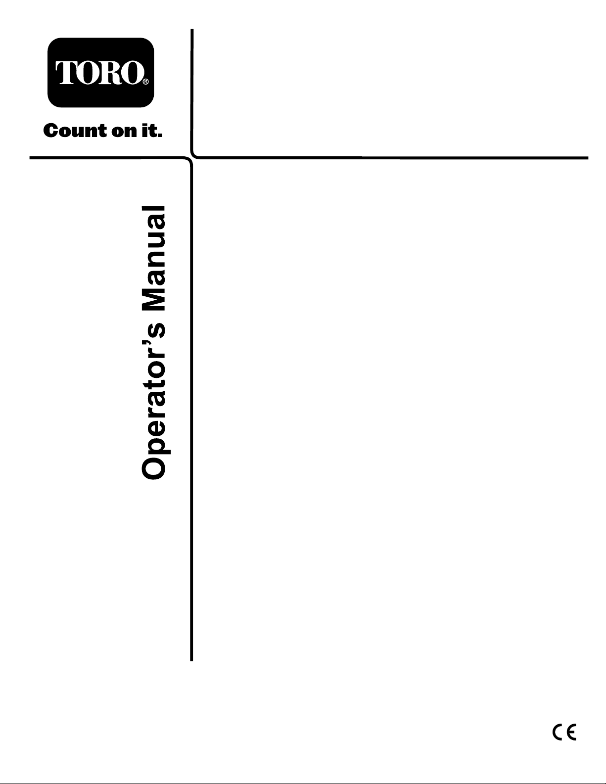
Figure1
identiesthelocationofthemodelandserialnumbers
ontheproduct.Writethenumbersinthespace
provided.
Figure1
1.Locationofthemodelandserialnumbers
Contents
Introduction.................................................................2
Safety...........................................................................3
SafetyandInstructionalDecals.............................3
Setup............................................................................4
1Inspection.........................................................4
2CuttingUnitKickstand......................................4
3AdjustingtheRearShield...................................5
4MounttheCounterWeights...............................5
5InstallingtheTipperRollerKit
(Optional)........................................................6
6InstallingtheFixedPlateKit(Optional)..............6
ProductOverview........................................................8
Specications.......................................................8
CuttingUnitAccessoriesandKits(seeparts
catalogforpartnumbers)..................................8
Operation.....................................................................9
Adjustments.........................................................9
HeightofCutChartTerms.................................10
HeightofCutChart............................................11
ServicingBedknife.............................................13
Maintenance...............................................................15
Lubrication.........................................................15
AdjustingtheReelBearings................................15
ServicingtheBedbar...........................................16
ServicingtheRoller............................................17
©2011—TheToro®Company
8111LyndaleAvenueSouth
Bloomington,MN55420
Contactusatwww.T oro.com.
2
PrintedintheUSA.
AllRightsReserved
Page 3
Safety
Hazardcontrolandaccidentpreventionare
dependentupontheawareness,concern,and
propertrainingofthepersonnelinvolvedinthe
operation,transport,maintenance,andstorageof
themachine.Improperuseormaintenanceofthe
machinecanresultininjuryordeath.Toreduce
thepotentialforinjuryordeath,complywiththe
followingsafetyinstructions.
•Read,understand,andfollowallinstructionsinthe
tractionunitandcuttingunitoperatorsmanual’s
beforeoperatingthecuttingunit.
•Neverallowchildrentooperatethetractionunitor
cuttingunits.Donotallowadultstooperatetraction
unitorcuttingunitswithoutproperinstruction.
Onlytrainedoperatorswhohavereadthismanual
shouldoperatethetractionunitorcuttingunits.
•Neveroperatethecuttingunitswhenunderthe
inuenceofdrugsoralcohol.
•Lightningcancausesevereinjuryordeath.If
lightningisseenorthunderisheardinthearea,do
notoperatethemachine;seekshelter.
•Keepallshieldsandsafetydevicesinplace.Ifa
shield,safetydeviceordecalisillegibleordamaged,
repairorreplaceitbeforeoperationiscommenced.
Alsotightenanyloosenuts,bolts,andscrewsto
ensurecuttingunitisinsafeoperatingcondition.
•Alwayswearsubstantialshoes.Donotoperate
cuttingunitswhilewearingsandals,tennisshoes,
sneakersorshorts.Also,donotwearloosetting
clothingwhichcouldgetcaughtinmovingparts.
Alwayswearlongpantsandsubstantialshoes.
Wearingsafetyglasses,safetyshoesandahelmetis
advisableandrequiredbysomelocalordinancesand
insuranceregulations.
•Removealldebrisorotherobjectsthatmightbe
pickedupandthrownbythecuttingunitreelblades.
Keepallbystandersawayfromtheworkingarea.
•Ifthecuttingbladesstrikeasolidobjectortheunit
vibratesabnormally,stopandshuttheengineoff.
Checkcuttingunitfordamagedparts.Repairany
damagebeforerestartingandoperatingthecutting
unit.
•Lowerthecuttingunitstothegroundandremove
keyfromignitionswitchwhenevermachineisleft
unattended.
•Besurecuttingunitsareinsafeoperatingcondition
bykeepingnuts,boltsandscrewstight.
•Removekeyfromignitionswitchtoprevent
accidentalstartingoftheenginewhenservicing,
adjustingorstoringthemachine.
•Performonlythosemaintenanceinstructions
describedinthismanual.Ifmajorrepairsare
everneededorassistanceisdesired,contactan
AuthorizedToroDistributor.
•Toensureoptimumperformanceandsafety,always
purchasegenuineTororeplacementpartsand
accessoriestokeeptheT oroallToro.Neveruse
"will-t"replacementpartsandaccessories
madebyothermanufacturers.Lookforthe
Torologotoassuregenuineness.Usingunapproved
replacementpartsandaccessoriescouldvoidthe
warrantyofTheToroCompany.
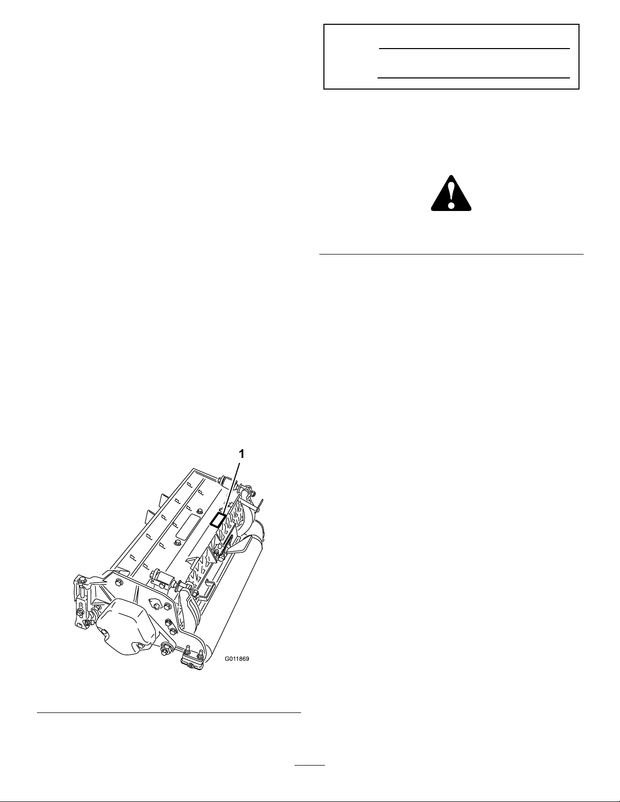
SafetyandInstructionalDecals
Safetydecalsandinstructionsareeasilyvisibletotheoperatorandarelocatednearanyareaof
potentialdanger.Replaceanydecalthatisdamagedorlost.
93-6688
1.Warning—readthe
instructionsbefore
servicingorperforming
maintenance.
2.Cuttinghazardofhandor
foot—stoptheengineand
waitformovingpartsto
stop.
3
Page 4

Setup
LooseParts
Usethechartbelowtoverifythatallpartshavebeenshipped.
ProcedureDescription
1
2
3
4
5
6
Cuttingunit
Nopartsrequired
Nopartsrequired
Nopartsrequired
Tipperrollerkit(notincluded)
Fixedplatekit(notincluded)
MediaandAdditionalParts
Description
Partscatalog1
Operator’sManual
CerticateofCompliance
Qty.
1Inspectthecuttingunit
–
–
–
1Installtheoptionaltipperrollerkit
1
Qty.
Usetoreferencepartnumbers
1Reviewthemanualandsaveinanappropriateplace
1
CEcompliance
Usethekickstandwhentippingthe
cuttingunit
Adjusttherearshield
Mountthecounterweights
InstalltheOptionalFixedPlateKit
Use
Use
O-ring
Screws
Note:Determinetheleftandrightsidesofthemachine
fromthenormaloperatingposition.
1
Inspection
Partsneededforthisprocedure:
1
Cuttingunit
Procedure
Afterthecuttingunitisremovedfromthebox,inspect
thefollowing:
1.Checkeachendofthereelforgrease.Greaseshould
bevisiblyevidentinthereelbearingsandinternal
splinesofthereelshaft.
1Usewhenmountingreelmotortocuttingunit
2Usetomountreelmotortocuttingunit
2.Ensurethatallnutsandboltsaresecurelytightened.
3.Makesurethecarrierframesuspensionoperates
freelyanddoesnotbindwhenmovedbackandforth.
2
CuttingUnitKickstand
NoPartsRequired
Procedure
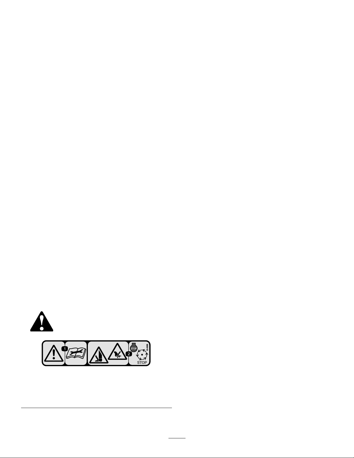
Wheneverthecuttingunithastobetippedtoexposethe
bedknife/reel,propuptherearofthecuttingunitwith
thekickstand(suppliedwiththetractionunit)tomake
surethenutsonthebackendofthebedbaradjusting
screwsarenotrestingontheworksurface(
Figure3).
4
Page 5
1.Cuttingunitkickstand
Figure3
1.Rearshield
Figure4
2.Capscrew
4
3
AdjustingtheRearShield
NoPartsRequired
Procedure
Undermostconditions,bestdispersionisattained
whentherearshieldisclosed(frontdischarge).When
conditionsareheavyorwet,rearshieldmaybeopened.
Toopentherearshield(Figure4),loosenthecapscrew
securingtheshieldtotheleftsideplate,rotatetheshield
totheopenpositionandtightenthecapscrew .
MounttheCounterWeights
NoPartsRequired
Procedure
Allcuttingunitsareshippedwiththecounterweight
mountedtotheleftendofthecuttingunit.Usethe
followingdiagramtodeterminethepositionofthe
counterweightsandreelmotors.
Figure5
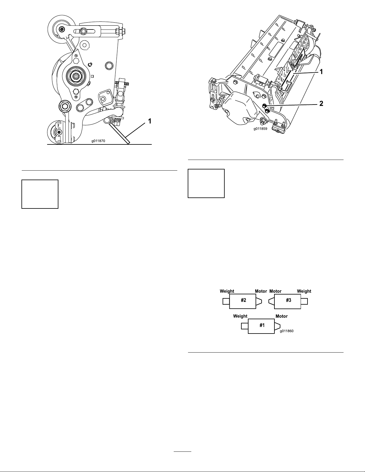
1.Onthe#3cuttingunit,removethe2capscrews
securingthecounterweighttotheleftendofthe
cuttingunit.Removethecounterweight(Figure6).
5
Page 6
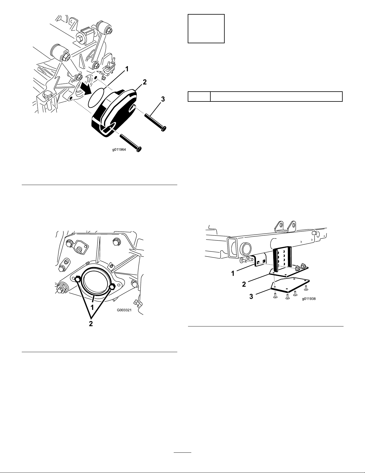
Figure6
G003321
1
2
1.O-ring
2.Counterweight
2.Onrightendofcuttingunit,removetheplasticplug
fromthebearinghousing(Figure7).
3.Removethe2capscrewsfromtherightsideplate
(Figure7).
3.Mountingbolts
5
InstallingtheTipperRollerKit
(Optional)
Partsneededforthisprocedure:
1
Tipperrollerkit(notincluded)
Procedure
Whencuttinginhigherheightsofcut,itisrecommended
thattheTipperRollerKitbeinstalled.
1.Raisethecuttingunitsallthewayup.
2.Locatetheframebracketabovethecentercutting
unit(Figure8).
3.Whilepressingdownonthefrontrollerofthecenter
cuttingunit,determinewhichholesonthetipper
bracketalignwiththeframebracketholestoattain
thesamerollercontactwhenthetipperbracketis
installed(
Figure8).
Figure7
1.Plasticplug
4.Installthecounterweighttotherightendofthe
cuttingunitwiththe2screwspreviouslyremoved.
5.Looselyinstallthe2reelmotormountingcapscrews
totheleftsideplateofthecuttingunit(Figure7).
2.Capscrew(2)
Figure8
1.Framebracket2.Tipperbracket
4.Lowerthecuttingunitsandmountthetipperbracket
totheframewiththe(2)carriageboltsandnuts
suppliedwiththekit(Figure8).
6
Page 7

6
InstallingtheFixedPlateKit
(Optional)
Partsneededforthisprocedure:
1
Fixedplatekit(notincluded)
Procedure
1.Removethenutsandwasherssecuringtheliftlinks
tothecuttingunitsideplateandcarrierframe
(Figure10).
Figure9
1.Nuts2.Washers
2.Usingthenumber2holes,insertaxedplateonto
theboltsandsecurewiththenutsremoved.The
number1holesaretobepositionedtowardthe
front.Donotreusethewashers.
Figure10
1.Nuts2.Fixedplate
3.Loosenthelocknutssecuringtheheight-of-cut
bracketstothecuttingunitsideplates(Figure11).
Figure11
1.Height-of-cutbracket
2.Locknut
4.Removetheheight-of-cutbracketsandtheroller
fromthecuttingunit.
5.Repeattheprocedureontheremainingcuttingunits.
3.Adjustingscrew
Note:Number1isalessaggressivesettingand
number3isamoreaggressivesetting.
7
Page 8

ProductOverview
Specications
Weight
27inch5Blade–148lb.(67kg)27inch8Blade–153lb.(69kg)
27inch11Blade–158lb.(72kg)32inch8Blade–167lb.(76kg)
CuttingUnitAccessoriesandKits(see
partscatalogforpartnumbers)
Note:Allaccessoriesandkitsare1percuttingunit
unlessotherwisespecied.
GrassBasketKit:Aseriesofclippingcollectionbaskets
attachedtothecuttingunitstocollectgrassclippings.
TipperRollerKit:Anadjustablebracketinstalledon
thetractionunitframe,whichwhenthecuttingunitsare
raised,thecentercuttingunitfrontrollercontactsthe
bracketandcausestherearrollertoriseforincreased
groundclearance.Recommendedforhigherheightsof
cut.
RearRollerBrushKit:Ahighspeed,highcontact
brushthatkeepstherearrollerfreeofgrassanddebris,
whichmaintainsaconsistentheightofcutandprevents
clumping.Thisleadstoabetterafter-cutappearance.
Comb/ScraperKit:Axedcombinstalledbehindthe
frontrollerwhichhelpsreducegrainandspongyturfby
standingupthegrassbeforecutting.Ascraperforthe
frontWiehlerollerisincludedinthekit.
FixedPlateKit:Boltingonxedplatesoverthe
suspensionmountinglinksremovesthepitchmovement
ofthecuttingunit.Recommendedforuseonlevel
surfacesandforhigherheightsofcut(greaterthan1.50
inches[38mm]).Becausethefrontrollerisremoved
whenusingthexedplates,thequalityofcut(efciency
ofcut)isincreased.
ShoulderRoller:Helpsreduceover-lapmarksfor
warmseasongrasses(Bermuda,Zoysia,Paspalum).
CollarKit(6neededperroller):Helpsreduceover
lapmarksforwarmseasongrasses(Bermuda,Zoysia,
Paspalum).Thiskitisinstalledontheouterthree
groovesoftheexistingWiehleroller,butisnotas
aggressiveastheShoulderroller.
ShortRearRoller:Helpsreducedoublerollermarks
forcoolseasongrasses(Bent,Bluegrass,Rye).
FullFrontRoller:Helpsproducemorepronounced
striping(repeatedcuttinginthesamedirection/path),
however,effectiveheightofcutisraisedandqualityof
cutisreduced.
Scrapers(Wiehle,Shoulder,Rearroller,FullFront
Roller):Fixedscrapersforalloptionalrollersare
availableforreducinggrassbuilduponrollerswhich
canaffectheightofcutsettings.
RollerRebuildKit:Includesallthebearings,bearing
nuts,innersealsandoutersealsrequiredtorebuilda
roller.
RollerRebuildToolKit:Includesallthetoolsandthe
installationinstructionsrequiredtorebuildarollerwith
therollerrebuildkit.
8
Page 9

Operation
G003323G003323
Note:Determinetheleftandrightsidesofthe
machinefromthenormaloperatingposition.
Adjustments
AdjustingtheBedknifetotheReel
Bedknifetoreeladjustmentisaccomplishedby
looseningortighteningbedbaradjustingscrews,located
ontopofmower.
1.Positionmachineonaat,levelworksurface.Make
surereelcontactisremovedbyturningbedbar
adjustingscrewscounterclockwise(
Figure12
1.Bedbaradjustingscrew
Figure12).
2.Tiltmoweronback,ontothecuttingunitkickstand,
toexposebedknifeandreel.
Important:Makesurenutsonbackendof
bedbaradjustingscrewsarenotrestingonthe
worksurface(
Figure12).
Figure13
4.Checkforlightcontactatotherendofreelusing
paperandadjustasrequired.
5.Afteradjustmentisaccomplished,checktoseeif
reelcanpinchpaperwheninsertedfromthefront
andcutpaperwheninsertedatarightangletothe
bedknife(Figure13).Itshouldbepossibletocut
paperwithminimumcontactbetweenthebedknife
andthereelblades.Ifexcessivecontact/reeldrag
isevidentitwillbeeithernecessarytobacklapor
regrindthecuttingunittoachievethesharpedges
neededforprecisioncutting(RefertotheToro
manualforSharpeningReelandRotaryMowers,
FormNo.80-300PT).
AdjustingtheRearRoller
1.Adjusttherearrollerbrackets(Figure14)tothe
desiredheightofcutrangebypositioningthe
requiredamountofspacersbelowthesideplate
mountingange(Figure14)pertheHOCChart.
3.Atoneendofreel,insertastripofnewspaper
betweenreelandbedknife(Figure13).Whileslowly
rotatingreelforward,turnbedbaradjustingscrew
Figure12)clockwise(onsameendofreel,one
(
clickatatime,untilpaperispinchedlightly,when
insertedfromthefront,paralleltothebedknife.A
slightdragwillbenotedasthepaperispulled.
Note:Eachtimeadjustingscrewisrotatedone
clickclockwise,bedknifemoves.0009in(.023mm).
closertoreel.Donotovertightentheadjusting
screws.
Figure14
1.Spacer3.Sideplatemountingange
2.Rollerbracket
2.Raiserearofcuttingunitandplaceablockunder
bedknife.
3.Remove(2)nutssecuringeachrollerbracketand
spacertoeachsideplatemountingange.
4.Lowerrollerandscrewsfromsideplatemounting
angesandspacers.
5.Placespacersontoscrewsonrollerbrackets.
9
Page 10

6.Re-securerollerbracketandspacerstounderside
ofsideplatemountingangeswithnutspreviously
removed.
regularlytodeterminethedesiredbenchsetheightof
cut.
7.Verifythatbedknifetoreelcontactiscorrect.Tip
mowertoexposefrontandrearrollersandbedknife.
Note:Thepositionoftherearrollertothe
reeliscontrolledbythemachiningtolerances
oftheassembledcomponentsandparallelingis
notrequired.Alimitedamountofadjustmentis
possiblebysettingthecuttingunitonasurface
plateandlooseningthesideplatemountingcap
screws(
Figure15).Adjustandretightencapscrews.
Torquethecapscrewsto27-33ft-lb(37-45N-m).
AggressivenessofCut
CuttingunitAggressivenessofCuthasasignicant
impactontheperformanceofthecuttingunit.
AggressivenessofCutreferstotheangleofthe
bedkniferelativetotheground(
Thebestcuttingunitsetupisdependentonyour
turfconditionsanddesiredresults.Experiencewith
thecuttingunitonyourturfwilldeterminethebest
settingtouse.Aggressivenessofcutmaybeadjusted
throughoutthecuttingseasontoallowforvariousturf
conditions.
Ingeneral,lesstonormalaggressivesettingsare
moreappropriateforwarmseasongrasses(Bermuda,
Paspalum,Zoysia)whilecoolseasongrasses(Bent,
Bluegrass,Rye)mayrequirenormaltomoreaggressive
setups.Moreaggressivesetupscutmoregrassoffby
allowingthespinningreeltopullmoregrassupinto
thebedknife.
Figure16).
Figure15
1.Sideplatemountingcapscrews
HeightofCutChartTerms
HeightofCutSetting(HOC)
ThedesiredHeightofCut.
BenchSetHeightofCut
Theheightatwhichthetopedgeofthebedknifeisset
aboveaatlevelsurfacethatcontactsthebottomof
boththefrontandrearroller.
EffectiveHeightofCut
Thisistheactualheightthegrasshasbeencut.For
agivenbenchsetheightofcut,theactualheightof
cutwillvarydependingonthetypeofgrass,timeof
year,turfandsoilconditions.Thecuttingunitsetup
(aggressivenessofcut,rollers,bedknives,attachments
installed,turfcompensationsettings,etc.)willalso
affecttheeffectiveheightofcut.Checktheeffective
heightofcutusingtheTurfEvaluator,Model04399
Figure16
1.Rearspacers
2.Sideplatemountingange
3.Aggressivenessofcut
RearSpacers
Thenumberofrearspacersdeterminesthe
aggressivenessofcutforthecuttingunit.Foragiven
heightofcut,addingspacers,belowthesideplate
mountingange,increasestheaggressivenessofthe
cuttingunit.Allcuttingunitsonagivenmachinemust
besettothesameaggressivenessofcut(Numberof
rearspacers,partno.119–0626),otherwisetheafter-cut
appearancecouldbenegativelyaffected(
Figure16).
10
Page 11

HeightofCutChart
HOCSetting
0.250"(6mm)
0.375"(9mm)
0.500"(13mm)
0.625"(16mm)
0.750"(19mm)
0.875"(22mm)
1.000"(25mm)
1.125"(29mm)
1.250"(32mm)
1.375"(35mm)
1.500"(38mm)
1.625"(41mm)
1.750"(44mm)
1.875"(48mm)
2.000"(51mm)
2.125"(54mm)*
2.250"(57mm)*
2.375"(60mm)*
2.500"(64mm)*
Aggressiveness
ofCut
Less
Normal
More
Less
Normal
More
Less
Normal
More
Less
Normal
More
Less
Normal
More
Less
Normal
More
Less
Normal
More
Less
Normal
More
Less
Normal
More
Less
Normal
More
Less
Normal
More
Less
Normal
More
Less
Normal
More
Less
Normal
More
Less
Normal
More
Less
Normal
More
Less
Normal
More
Less
Normal
More
No.ofRear
Spacers
0
0
1
0
1
2
0
1
2
1
2
3
2
3
4
2
3
4
3
4
5
4
5
6
4
5
6
4
5
6
5
6
7
6
7
8
6
7
8
7
8
9
7
8
9
8
9
10
8
9
10
9
10
11
*FixedPlateKits(PartNo.119–0646–03)arerecommended
for2.00to2.5inch(51to64mm)heightsofcut.
AdjustingtheHeightofCut
1.Loosenlocknutssecuringheight-of-cutbracketsto
cuttingunitsideplates(Figure17).
1.Height-of-cutbracket
2.Locknut
2.Loosennutongaugebar(Figure18)andset
adjustingscrewtodesiredheight-of-cut.Distance
betweenbottomofscrewheadandfaceofbaris
height-of-cut.
1.Gaugebar
2.Heightadjustingscrew
3.Hookthescrewheadoncuttingedgeofbedknife
andrestrearendofbaronrearroller(Figure19).
4.Rotatetheadjustingscrewuntilthefrontroller
contactsthegaugebar(Figure19).Adjustbothends
Less
Normal
More
Figure17
3.Adjustingscrew
Figure18
3.Nut
9
10
11
ofrolleruntilentirerollerisparalleltothebedknife.
11
Page 12

Figure19
Important:Whensetproperly,therearand
frontrollerswillcontactthegaugebarandthe
screwwillbesnugagainstthebedknife.This
ensuresthattheheight-of-cutisidenticalat
bothendsofthebedknife.
5.Tightennutstosecureadjustment.Donot
overtightennut.Tightenenoughtoremoveplay
fromwasher.
Figure20
1.BedknifeLipHeight*
6.Toadjusttheheightofcutwhenxedplatekitsare
installedonthecuttingunits,proceedasfollows:
•Removetheheightofcutbracketsandfront
rollerasdescribedinProcedure6intheSet-Up
section.
•Installthecuttingunitontothetractionunit
asdescribedintheTractionUnitOperator’s
Manual.
•Lowerthecuttingunittotheoorandmeasure
thedistancefromtheoortothetopofthe
bedknife,asshownin
Figure21
Usethefollowingcharttodeterminewhich
bedknifeisbestsuitedforthedesiredheightofcut.
Bedknife/HeightofCutChart
Bedknife
LowHOC
(Optional)
EdgeMax®
(Optional)
Standard
(Production)
HeavyDuty
(Optional)
PartNo.
120–1641
(27inch)
120–1642
(32inch)
112-8910
(27inch)
112–8956
(32inch)
114–9388
(27inch)
114–9389
(32inch)
114–9390
(27inch)
114–9391
(32inch)
Bedknife
LipHeight
*
.220inch
(5.6mm)
.270inch
(6.9mm)
.270inch
(6.9mm)
.370inch
(9.3mm)
HeightofCut
.250-.500inch
(6.4–12.7mm)
.375-2.50inches*
(9.5–63.5mm)
.375-2.50inches*
(9.5–63.5mm)
.500-2.50inches
(12.7-63.5mm)
*WarmseasongrassesmayrequiretheLowHOC
bedknifefor.500inches(12.7mm)andbelow.
Figure21
1.Fixedplate
2.Uppermountingholes
3.Rearheightofcutspacers
4.Heightofcut
•Toattainthedesiredheightofcut,adjustthe
rearrollerbracketstothedesiredheightofcut
rangebypositioningtherequiredamountof
spacersbelowthesideplatemountingange
pertheHOCChart.RefertoAdjustingtheRear
Roller.
Note:Toachievealessaggressivecut,mount
thecuttingunitlinksinthenumber1position
ormountthelinkstothenumber3positionfor
amoreaggressivecut.
12
Page 13

CuttingUnitCharacteristics
Thedualknobbedknife-to-reeladjustmentsystem
incorporatedinthiscuttingunitsimpliesthe
adjustmentprocedureneededtodeliveroptimum
mowingperformance.Thepreciseadjustment
possiblewiththedualknob/bedbardesigngivesthe
necessarycontroltoprovideacontinualself-sharpening
action-thusmaintainingsharpcuttingedges,ensuring
goodquality-of-cut,andgreatlyreducingtheneedfor
routinebacklapping.
DailyAdjustmentsofCuttingUnit
Note:Overtime,thechamfer(
Figure22)willneed
toberegroundasitisonlydesignedtolast40%
ofthebedknifelife.
Priortomowingeachday,orasrequired,eachcutting
unitmustbecheckedtoverifyproperbedknife-to-reel
contact.Thismustbeperformedeventhough
qualityofcutisacceptable.
1.Lowerthecuttingunitsontoahardsurface,shutoff
theengine,andremovetheignitionkey.
2.Slowlyrotatethereelinareversedirection,
listeningforreel-to-bedknifecontact.Ifnocontact
isevident,turnthebedknifeadjustingknobs
clockwise,oneclickatatime,untillightcontactis
feltandheard.
Note:Thereelmustcutonesheetofpaper,when
insertedatarightangletothebedknife,atboth
endsandthecenterofthereel.
Note:Theadjustmentknobshavedetents
correspondingto0.0009inch(0.023mm)bedknife
movementforeachindexedposition.
3.Ifexcessivecontactisneededtocutpaper,
backlappingorgrindingisrequired.
Important:Lightcontactispreferredatall
times.Iflightcontactisnotmaintained,
thebedknife/reeledgeswillnotsufciently
self-sharpenanddullcuttingedgeswillresult
afteraperiodofoperation.Ifexcessivecontact
ismaintained,bedknife/reelwearwillbe
accelerated,unevenwearcanresult,andquality
ofcutmaybeadverselyaffected.
Note:Asthereelbladescontinuetorunagainst
thebedknife,aslightburrwillappearonthefront
cuttingedgesurfacealongthefulllengthofthe
bedknife.Ifaleisoccasionallyrunacrossthe
frontedgetoremovethisburr,improvedcutting
canbeobtained.
Afterextendedrunning,aridgewilleventually
developatbothendsofthebedknife.Thesenotches
mustberoundedofforledushwiththecutting
edgeofthebedknifetoensuresmoothoperation.
Figure22
1.Lead-inchamferonright
endofbedknife
2..060inch(1.5mm)
3..340inch(8.6mm)
Note:Donotmakelead-inchamfertoolargeas
itmaycauseturftufting.
ServicingBedknife
Thebedknifeservicelimitsarelistedinthefollowing
charts.
Important:Operatingthecuttingunitwiththe
bedknifebelowthe“servicelimit”mayresultin
poorafter-cutappearanceandreducethestructural
integrityofthebedknifeforimpacts.
BedknifeServiceLimitChart
Bedknife
LowHOC
(Optional)
EdgeMax®
(Optional)
Standard
(Production)
HeavyDuty
(Optional)
Note:Therecommendedtopandfrontbedknifegrind
angleis3to7degrees(Figure23).
PartNo.
120–1641
(27inch)
120–1642
(32inch)
112-8910
(27inch)
112–8956
(32inch)
114–9388
(27inch)
114–9389
(32inch)
114–9390
(27inch)
114–9391
(32inch)
BedknifeLip
Height*
.220inch
(5.6mm)
.270inch
(6.9mm)
.270inch
(6.9mm)
.370inch
(9.3mm)
Service
Limit*
.190inch
(4.8mm)
.190inch
(4.8mm)
.190inch
(4.8mm)
.190inch
(4.8mm)
13
Page 14

Figure23
1.BedknifeServiceLimit*
Note:Allbedknifeservicelimitmeasurements
referencethebottomofthebedknife(Figure24)
Figure24
14
Page 15

Maintenance
G003331
Lubrication
Eachcuttingunithas(6)greasettings(Figure25)that
mustbelubricatedregularlywithNo.2GeneralPurpose
LithiumBaseGrease.
Thelubricationpointsarefrontroller(2),rearroller(2)
andreelbearing(2).
Figure26
1.Bedknifeadjustingknob
Note:Lubricatingcuttingunitsimmediatelyafter
washinghelpspurgewateroutofbearingsand
increasesbearinglife.
1.Wipeeachgreasettingwithacleanrag.
2.Applygreaseuntilcleangreaseisseencomingoutof
rollersealsandbearingreliefvalve.
3.Wipeexcessgreaseaway.
Figure25
1.Reliefvalve
2.Usingaragorthicklypaddedglove,holdontothe
reelbladeandtrytomovethereelassemblysideto
Figure27).
side(
Figure27
3.Ifendplayexists,proceededasfollows:
A.Loosenexternalsetscrewsecuringbearing
adjustingnuttobearinghousinglocatedonthe
leftsideofthecuttingunit(Figure28).
AdjustingtheReelBearings
Toensurelonglifeofthereelbearings,periodically
checkifreelendplayexists.Thereelbearingscanbe
checkedandadjustedasfollows:
1.Loosenreeltobedknifecontactbyturning
thebedknifeadjustingknobs(Figure26)
counterclockwiseuntilnocontactexists.
Figure28
B.Usinga1-3/8"socketwrench,slowlytightenthe
reelbearingadjustmentnutuntilnoendplayof
thereelexists.Ifadjustingnutdoesnoteliminate
reelendplay,replacereelbearings.
15
Page 16

Note:Reelbearingsdonotrequirepreload.
Overtighteningreelbearingadjusternutwill
damagereelbearings.
4.Retightensetscrewsecuringbearingadjustingnutto
bearinghousing.Torqueto12-15in-lb.
ServicingtheBedbar
RemovingtheBedbar
1.Turnbedbaradjusterscrews,counterclockwise,to
backbedknifeawayfromreel(Figure29).
Figure29
1.Bedbaradjustingscrew3.Bedbar
2.Springtensionnut
2.Backoutthespringtensionnut,untilthewasheris
nolongertensionedagainstthebedbar(Figure29).
3.Oneachsideofthemachine,loosenthelocknut
securingthebedbarbolt(Figure30).
4.Washer
Figure31
1.Bedbarbolt
2.Nut4.Nylonwasher
3.Steelwasher
AssemblingtheBedbar
1.Installbedbar,positioningmountingearsbetween
washerandbedbaradjuster.
2.Securebedbartoeachsideplatewithbedbarbolts
(nutsonbolts)and6washers.Anylonwasheristo
bepositionedoneachsideofsideplateboss.Place
asteelwasheroutsideeachofthenylonwashers
Figure31).T orquebedbarboltsto27-33(37-45
(
N-m).Tightenlocknutsuntiltheoutsidesteel
washerstopsrotatingandendplayisremovedbut
donotovertightenordeectsideplates.Washers
oninsidemayhaveagap.
Figure30
1.Bedbarbolt2.Locknut
4.Removeeachbedbarboltallowingbedbartobe
pulleddownwardandremovedfrommachinebolt
(Figure30).Accountfor2nylonand1stampedsteel
washersoneachendofbedbar(Figure31).
3.Tightenspringtensionnutuntilspringiscollapsed,
thenbackoff1/2turn(
Figure32).
Note:Donotovertightenasdamagetothespring
mayoccur.
Figure32
1.Springtensionnut2.Spring
16
Page 17

ServicingtheRoller
ARollerRebuildKit,PartNo.114–5430andaRoller
RebuildToolKit,PartNo.115–0803(Figure33)are
availableforservicingtheroller.TheRollerRebuildKit
includesallthebearings,bearingnuts,innersealsand
outersealstorebuildaroller.TheRollerRebuildTool
Kitincludesallthetoolsandtheinstallationinstructions
requiredtorebuildarollerwiththerollerrebuildkit.
Refertoyourpartscatalogorcontactyourdistributor
forassistance.
Figure33
1.Rebuildkit(PartNo.114–5430)
2.Rebuildtoolkit(PartNo.1 15–0803)
3.Innerseal8.Washer
4.Bearing
5.Outerseal
6.Bearingnut
7.Innersealtool
9.Bearing/outersealtool
17
Page 18

Notes:
18
Page 19

Notes:
19
Page 20

TheToroTotalCoverageGuarantee
ALimitedWarranty
ConditionsandProductsCovered
TheT oro
toanagreementbetweenthem,jointlywarrantyourT oroCommercial
product(“Product”)tobefreefromdefectsinmaterialsorworkmanship
fortwoyearsor1500operationalhours*,whicheveroccursrst.This
warrantyisapplicabletoallproductswiththeexceptionofAerators
(refertoseparatewarrantystatementsfortheseproducts).Wherea
warrantableconditionexists,wewillrepairtheProductatnocosttoyou
includingdiagnostics,labor,parts,andtransportation.Thiswarranty
beginsonthedatetheProductisdeliveredtotheoriginalretailpurchaser.
*Productequippedwithanhourmeter.
®
Companyanditsafliate,T oroWarrantyCompany,pursuant
InstructionsforObtainingWarrantyService
YouareresponsiblefornotifyingtheCommercialProductsDistributoror
AuthorizedCommercialProductsDealerfromwhomyoupurchasedthe
Productassoonasyoubelieveawarrantableconditionexists.Ifyouneed
helplocatingaCommercialProductsDistributororAuthorizedDealer,or
ifyouhavequestionsregardingyourwarrantyrightsorresponsibilities,
youmaycontactusat:
CommercialProductsServiceDepartment
ToroWarrantyCompany
811 1LyndaleAvenueSouth
Bloomington,MN55420-1196
E-mail:commercial.warranty@toro.com
OwnerResponsibilities
AstheProductowner,youareresponsibleforrequiredmaintenance
andadjustmentsstatedinyourOperator’sManual.Failuretoperform
requiredmaintenanceandadjustmentscanbegroundsfordisallowinga
warrantyclaim.
ItemsandConditionsNotCovered
Notallproductfailuresormalfunctionsthatoccurduringthewarranty
periodaredefectsinmaterialsorworkmanship.Thiswarrantydoesnot
coverthefollowing:
•Productfailureswhichresultfromtheuseofnon-T ororeplacement
parts,orfrominstallationanduseofadd-on,ormodiednon-Toro
brandedaccessoriesandproducts.Aseparatewarrantymaybe
providedbythemanufactureroftheseitems.
•Productfailureswhichresultfromfailuretoperformrecommended
maintenanceand/oradjustments.Failuretoproperlymaintainyour
ToroproductpertheRecommendedMaintenancelistedinthe
Operator’sManualcanresultinclaimsforwarrantybeingdenied.
•ProductfailureswhichresultfromoperatingtheProductinan
abusive,negligentorrecklessmanner.
•Partssubjecttoconsumptionthroughuseunlessfoundtobe
defective.Examplesofpartswhichareconsumed,orusedup,during
normalProductoperationinclude,butarenotlimitedto,brakes
padsandlinings,clutchlinings,blades,reels,bedknives,tines,
sparkplugs,castorwheels,tires,lters,belts,andcertainsprayer
componentssuchasdiaphragms,nozzles,andcheckvalves,etc.
•Failurescausedbyoutsideinuence.Itemsconsideredtobeoutside
inuenceinclude,butarenotlimitedto,weather,storagepractices,
contamination,useofunapprovedcoolants,lubricants,additives,
fertilizers,water,orchemicals,etc.
•Normalnoise,vibration,wearandtear,anddeterioration.
•Normal“wearandtear”includes,butisnotlimitedto,damageto
seatsduetowearorabrasion,wornpaintedsurfaces,scratched
decalsorwindows,etc.
Parts
Partsscheduledforreplacementasrequiredmaintenancearewarranted
fortheperiodoftimeuptothescheduledreplacementtimeforthatpart.
Partsreplacedunderthiswarrantyarecoveredforthedurationofthe
originalproductwarrantyandbecomethepropertyofT oro.T orowill
makethenaldecisionwhethertorepairanyexistingpartorassemblyor
replaceit.Toromayuseremanufacturedpartsforwarrantyrepairs.
NoteRegardingDeepCycleBatteryWarranty:
Deepcyclebatterieshaveaspeciedtotalnumberofkilowatt-hoursthey
candeliverduringtheirlifetime.Operating,recharging,andmaintenance
techniquescanextendorreducetotalbatterylife.Asthebatteriesinthis
productareconsumed,theamountofusefulworkbetweencharging
intervalswillslowlydecreaseuntilthebatteryiscompletelywornout.
Replacementofwornoutbatteries,duetonormalconsumption,isthe
responsibilityoftheproductowner.Batteryreplacementmayberequired
duringthenormalproductwarrantyperiodatowner’sexpense.
MaintenanceisatOwner’sExpense
Enginetune-up,lubricationcleaningandpolishing,replacementof
ItemsandConditionsNotCoveredlters,coolant,andcompleting
RecommendedMaintenancearesomeofthenormalservicesT oro
productsrequirethatareattheowner’sexpense.
GeneralConditions
RepairbyanAuthorizedT oroDistributororDealerisyoursoleremedy
underthiswarranty.
NeitherTheToroCompanynorToroWarrantyCompanyisliablefor
indirect,incidentalorconsequentialdamagesinconnectionwiththe
useoftheT oroProductscoveredbythiswarranty,includingany
costorexpenseofprovidingsubstituteequipmentorserviceduring
reasonableperiodsofmalfunctionornon-usependingcompletion
ofrepairsunderthiswarranty.ExceptfortheEmissionswarranty
referencedbelow,ifapplicable,thereisnootherexpresswarranty.
Allimpliedwarrantiesofmerchantabilityandtnessforusearelimitedto
thedurationofthisexpresswarranty.Somestatesdonotallowexclusions
ofincidentalorconsequentialdamages,orlimitationsonhowlongan
impliedwarrantylasts,sotheaboveexclusionsandlimitationsmaynot
applytoyou.
Thiswarrantygivesyouspeciclegalrights,andyoumayalsohaveother
rightswhichvaryfromstatetostate.
Noteregardingenginewarranty:
TheEmissionsControlSystemonyourProductmaybecoveredby
aseparatewarrantymeetingrequirementsestablishedbytheU.S.
EnvironmentalProtectionAgency(EP A)and/ortheCaliforniaAir
ResourcesBoard(CARB).Thehourlimitationssetforthabovedonot
applytotheEmissionsControlSystemWarranty .RefertotheEngine
EmissionControlW arrantyStatementprintedinyourOperator’sManual
orcontainedintheenginemanufacturer’sdocumentationfordetails
CountriesOtherthantheUnitedStatesorCanada
CustomerswhohavepurchasedT oroproductsexportedfromtheUnitedStatesorCanadashouldcontacttheirToroDistributor(Dealer)toobtain
guaranteepoliciesforyourcountry ,province,orstate.IfforanyreasonyouaredissatisedwithyourDistributor’sserviceorhavedifcultyobtaining
guaranteeinformation,contacttheT oroimporter.Ifallotherremediesfail,youmaycontactusatToroWarrantyCompany.
374-0253RevA
 Loading...