

Page 1

FormNo.3363-312RevC
Reelmaster
ModelNo.03170—SerialNo.310000001andUp
ModelNo.03171—SerialNo.310000001andUp
ModelNo.03172
ModelNo.03173
®
3100-DTractionUnit
ToregisteryourproductordownloadanOperator'sManualorPartsCatalogatnocharge,gotowww.T oro.com.OriginalInstructions(EN)
Page 2
ModelNo.
Introduction
ThisproductcomplieswithallrelevantEuropean
directives,fordetailspleaseseetheseparateproduct
specicDeclarationofConformity(DOC)sheet.
WARNING
CALIFORNIA
Proposition65Warning
Dieselengineexhaustandsomeofits
constituentsareknowntotheStateof
Californiatocausecancer,birthdefects,
andotherreproductiveharm.
Thismachineisaride-on,reel-bladelawnmower
intendedtobeusedbyprofessional,hiredoperatorsin
commercialapplications.Itisprimarilydesignedfor
cuttinggrassonwell-maintainedlawnsinparks,golf
courses,sportselds,andoncommercialgrounds.Itis
notdesignedforcuttingbrush,mowinggrassandother
growthalongsidehighways,orforagriculturaluses.
Readthisinformationcarefullytolearnhowtooperate
andmaintainyourproductproperlyandtoavoidinjury
andproductdamage.Youareresponsibleforoperating
theproductproperlyandsafely.
SerialNo.
Thismanualidentiespotentialhazardsandhassafety
messagesidentiedbythesafetyalertsymbol(Figure2),
whichsignalsahazardthatmaycauseseriousinjury
ordeathifyoudonotfollowtherecommended
precautions.
Figure2
1.Safetyalertsymbol
Thismanualuses2otherwordstohighlightinformation.
Importantcallsattentiontospecialmechanical
informationandNoteemphasizesgeneralinformation
worthyofspecialattention.
Important:Thisengineisnotequippedwitha
sparkarrestermufer.ItisaviolationofCalifornia
PublicResourceCodeSection4442touseoroperate
theengineonanyforest-covered,brush-covered,or
grass-coveredland.Otherstatesorfederalareas
mayhavesimilarlaws.
YoumaycontactTorodirectlyatwww .Toro.comfor
productandaccessoryinformation,helpndingadealer,
ortoregisteryourproduct.
Wheneveryouneedservice,genuineToroparts,
oradditionalinformation,contactanAuthorized
ServiceDealerorToroCustomerServiceandhave
themodelandserialnumbersofyourproductready.
Figure1identiesthelocationofthemodelandserial
numbersontheproduct.Writethenumbersinthe
spaceprovided.
Figure1
1.Modelandserialnumberlocation
©2012—TheT oro®Company
8111LyndaleAvenueSouth
Bloomington,MN55420
Contactusatwww.Toro.com.
2
PrintedintheUSA
AllRightsReserved
Page 3

Contents
Introduction.................................................................2
Safety...........................................................................4
SafeOperatingPractices.......................................4
ToroMowerSafety...............................................6
SoundPowerLevel...............................................8
SoundPressureLevel...........................................8
VibrationLevel....................................................8
SafetyandInstructionalDecals.............................8
Setup.........................................................................13
1InstallingtheWheels........................................14
2InstallingtheSteeringWheel............................14
3Activating,Charging,andConnectingthe
Battery...........................................................15
4CheckingtheAngleIndicator...........................16
5InstallingtheHoodLatch(CEOnly)................16
6InstallingtheExhaustGuard(CE
Only)..............................................................17
7InstallingtheRollBar.......................................18
8InstallingtheFrontLiftArms...........................18
9InstallingtheCarrierFramestotheCutting
Units..............................................................19
10MountingtheCuttingUnits............................21
11MountingtheCuttingUnitDrive
Motors...........................................................21
12AdjustingtheLiftArms.................................22
ProductOverview......................................................24
Controls.............................................................24
Specications.....................................................26
Attachments/Accessories...................................26
Operation...................................................................27
CheckingtheEngineOilLevel............................27
FillingtheFuelTank...........................................27
CheckingtheCoolingSystem..............................28
CheckingtheHydraulicSystem...........................29
CheckingtheTirePressure.................................30
CheckingtheReel-to-BedknifeContact...............30
TorquingtheWheelNuts....................................30
StartingandStoppingtheEngine........................30
BleedingtheFuelSystem....................................30
CheckingtheInterlockSystem............................31
TowingtheTractionUnit....................................31
StandardControlModule(SCM)........................32
OperatingTips...................................................34
Maintenance...............................................................39
RecommendedMaintenanceSchedule(s)................39
DailyMaintenanceChecklist...............................40
ServiceIntervalChart.........................................41
PremaintenanceProcedures....................................41
RemovingtheHood...........................................41
Lubrication.............................................................42
GreasingtheBearingsAndBushings...................42
SealedBearings...................................................44
EngineMaintenance...............................................45
ServicingtheAirCleaner....................................45
ChangingtheEngineOilandFilter.....................45
FuelSystemMaintenance.......................................46
ServicingtheFuelTank......................................46
InspectingtheFuelLinesand
Connections...................................................46
DrainingtheWaterSeparator..............................46
ChangingtheFuelFilterCanister........................47
BleedingAirfromtheInjectors...........................47
ElectricalSystemMaintenance................................48
CaringfortheBattery.........................................48
StoringtheBattery..............................................48
Fuses..................................................................48
DriveSystemMaintenance.....................................49
AdjustingtheTractionDriveforNeutral.............49
CoolingSystemMaintenance..................................49
CleaningtheEngineCoolingSystem...................49
BrakeMaintenance.................................................50
AdjustingtheParkingBrake................................50
BeltMaintenance....................................................51
ServicingtheEngineBelts..................................51
ControlsSystemMaintenance.................................52
AdjustingtheThrottle........................................52
HydraulicSystemMaintenance...............................52
ChangingtheHydraulicFluid.............................52
ChangingtheHydraulicFilter.............................53
CheckingtheHydraulicLinesandHoses.............54
MiscellaneousMaintenance....................................54
BacklappingtheCuttingSystem..........................54
Storage.......................................................................55
PreparationforSeasonalStorage.........................55
Schematics.................................................................57
3
Page 4

Safety
ThismachinemeetsorexceedsCENstandardEN
836:1997(whenappropriatedecalsapplied),and
ANSIB71.4-2004specicationsineffectatthetime
ofproductionwhenequippedwithrequiredweights
aslistedintheweightchart.
◊Inadequatebraking
◊Thetypeofmachineisunsuitableforthetask
◊Lackofawarenessoftheeffectofground
conditions,especiallyslopes
◊Incorrecthitchingandloaddistribution
Improperuseormaintenancebytheoperator
orownercanresultininjury.T oreducethe
potentialforinjury,complywiththesesafety
instructionsandalwayspayattentiontothesafety
alertsymbol,whichmeansCaution,Warning,or
Danger—personalsafetyinstruction.Failureto
complywiththeinstructionmayresultinpersonal
injuryordeath.
SafeOperatingPractices
ThefollowinginstructionsarefromtheCENstandard
EN836:1997,ISOstandard5395:1990,andANSI
B71.4-2004.
Training
•ReadtheOperator’ sManualandothertrainingmaterial
carefully.Befamiliarwiththecontrols,safetysigns,
andtheproperuseoftheequipment.
•Iftheoperatorormechaniccannotreadthelanguage
ofthismanual,itistheowner’sresponsibilityto
explainthismaterialtothem.
•Neverallowchildrenorpeopleunfamiliarwiththese
instructionstouseorservicethemower.Local
regulationsmayrestricttheageoftheoperator.
•Nevermowwhilepeople,especiallychildren,orpets
arenearby .
•Keepinmindthattheoperatororuserisresponsible
foraccidentsorhazardsoccurringtootherpeopleor
theirproperty.
•Donotcarrypassengers.
•Alldriversandmechanicsshouldseekandobtain
professionalandpracticalinstruction.Theowneris
responsiblefortrainingtheusers.Suchinstruction
shouldemphasizethefollowing:
–Theneedforcareandconcentrationwhen
workingwithride-onmachines
–Controlofaride-onmachineslidingonaslope
willnotberegainedbytheapplicationofthe
brake.Themainreasonsforlossofcontrolare
asfollows:
◊Insufcientwheelgrip
◊Beingdriventoofast
Preparation
•Whilemowing,alwayswearsubstantialfootwear,
longtrousers,hardhat,safetyglasses,andhearing
protection.Longhair,looseclothing,orjewelrymay
gettangledinmovingparts.Donotoperatethe
equipmentwhenbarefootorwearingopensandals.
•Thoroughlyinspecttheareawheretheequipment
istobeusedandremoveallobjectswhichmaybe
thrownbythemachine.
•Warning—Fuelishighlyammable.Takethe
followingprecautions:
–Storefuelincontainersspecicallydesignedfor
thispurpose.
–Refueloutdoorsonlyanddonotsmokewhile
refueling.
–Addfuelbeforestartingtheengine.Never
removethecapofthefueltankoraddfuelwhile
theengineisrunningorwhentheengineishot.
–Iffuelisspilled,donotattempttostartthe
enginebutmovethemachineawayfromthe
areaofspillageandavoidcreatinganysourceof
ignitionuntilfuelvaporshavedissipated.
–Replaceallfueltankandcontainercapssecurely.
•Replacefaultysilencers/mufers.
•Evaluatetheterraintodeterminewhataccessories
andattachmentsareneededtoproperlyand
safelyperformthejob.Onlyuseaccessoriesand
attachmentsapprovedbythemanufacturer.
•Checkthatoperator’spresencecontrols,safety
switchesandshieldsareattachedandfunctioning
properly.Donotoperateunlesstheyarefunctioning
properly.
Operation
•Donotoperatetheengineinaconnedspacewhere
dangerouscarbonmonoxidefumescancollect.
•Mowonlyindaylightoringoodarticiallight.
•Beforeattemptingtostarttheengine,disengageall
bladeattachmentclutches,shiftintoneutral,and
engagetheparkingbrake.Onlystarttheenginefrom
4
Page 5

theoperator’ sposition.NeverremovetheROPSand
alwaysweartheseatbeltsduringoperation.
•Rememberthereisnosuchthingasasafeslope.
Travelongrassslopesrequiresparticularcare.Do
thefollowingtoguardagainstoverturning:
–Donotstoporstartsuddenlywhengoingupor
downhill.
–Keepmachinespeedslowonslopesandduring
tightturns.
–Stayalertforhumpsandhollowsandother
hiddenhazards.
–Nevermowacrossthefaceoftheslope,unless
themowerisdesignedforthispurpose.
•Stayalertforholesintheterrainandotherhidden
hazards.
•Watchoutfortrafcwhencrossingornearroadways.
•Stopthebladesfromrotatingbeforecrossing
surfacesotherthangrass.
•Whenusinganyattachments,neverdirectdischarge
ofmaterialtowardbystandersnorallowanyonenear
themachinewhileinoperation.
•Neveroperatethemachinewithdamagedguards,
shields,orwithoutsafetyprotectivedevicesinplace.
Besureallinterlocksareattached,adjustedproperly,
andfunctioningproperly.
•Donotchangetheenginegovernorsettingsor
overspeedtheengine.Operatingtheengineat
excessivespeedmayincreasethehazardofpersonal
injury.
•Dothefollowingbeforeleavingtheoperator’s
position:
–Stoponlevelground.
–Disengagethepowertake-offandlowerthe
attachments.
–Changeintoneutralandsettheparkingbrake.
–Stoptheengineandremovethekey.
•Disengagethedrivetoattachments,stopthe
engine,andremovetheignitionkeyinthefollowing
conditions:
–Beforerefueling
–Beforeremovingthegrasscatcher(s)
–Beforemakingheightadjustments,unlessthe
adjustmentcanbemadefromtheoperator’s
position.
–Beforeclearingblockages
–Beforechecking,cleaning,orworkingonthe
mower
–Afterstrikingaforeignobjectorifanabnormal
vibrationoccurs(checkimmediately).Inspect
themowerfordamageandmakerepairsbefore
restartingandoperatingtheequipment.
•Disengagethedrivetoattachmentswhen
transportingorwhenthemachineisnotinuse.
•Reducethethrottlesettingbeforestoppingthe
engineand,iftheengineisprovidedwithafuel
shut-offvalve,turnthefueloffattheconclusionof
mowing.
•Keephandsandfeetawayfromthecuttingunits.
•Lookbehindanddownbeforebackinguptobesure
ofaclearpath.
•Slowdownandusecautionwhenmakingturnsand
crossingroadsandsidewalks.Stopcylinders/reels
ifnotmowing.
•Donotoperatethemowerundertheinuenceof
alcoholordrugs.
•Lightningcancausesevereinjuryordeath.If
lightningisseenorthunderisheardinthearea,do
notoperatethemachine;seekshelter.
•Usecarewhenloadingorunloadingthemachine
intoatrailerortruck.
•Theoperatorshallturnonashingwarninglights,
ifprovided,whenevertravelingonapublicroad,
exceptwheresuchuseisprohibitedbylaw .
•Usecarewhenapproachingblindcorners,shrubs,
trees,orotherobjectsthatmayobscurevision.
MaintenanceandStorage
•Keepallnuts,boltsandscrewstighttobesurethe
equipmentisinsafeworkingcondition.
•Neverstoretheequipmentwithfuelinthetank
insideabuildingwherefumesmayreachanopen
ameorspark.
•Allowtheenginetocoolbeforestoringinany
enclosure.
•Toreducetherehazard,keeptheengine,
silencer/mufer,batterycompartmentfuelstorage
area,cuttingunitsanddrivesfreeofgrass,leaves,or
excessivegrease.Cleanupoilorfuelspillage.
•Keepallpartsingoodworkingconditionandall
hardwareandhydraulicttingstightened.Replace
wornordamagedpartsanddecalsforsafety .
•Ifthefueltankhastobedrained,dothisoutdoors.
•Becarefulduringadjustmentofthemachineto
prevententrapmentofthengersbetweenmoving
bladesandxedpartsofthemachine.
5
Page 6

•Onmulti-cylinder/multi-reelmachines,takecare
asrotatingonecylinder/reelcancauseother
cylinders/reelstorotate.
•Disengagedrives,lowerthecuttingunits,setparking
brake,stopengineandremovekey.Waitforall
movementtostopbeforeadjusting,cleaningor
repairing.
•Cleangrassanddebrisfromcuttingunits,drives,
silencers/mufers,andenginetohelppreventres.
Cleanupoilorfuelspillage.
•Shutofffuelwhilestoringortransporting.Donot
storefuelnearames.
•Parkthemachineonlevelground.
•Neverallowuntrainedpersonneltoservicethe
machine.
•Usejackstandstosupportcomponentswhen
required.
•Carefullyreleasepressurefromcomponentswith
storedenergy.
•Disconnectbatterybeforemakinganyrepairs.
Disconnectthenegativeterminalrstandthe
positivelast.Reconnectpositiverstandnegative
last.
•Usecarewhencheckingthecylinders/reels.Wear
glovesandusecautionwhenservicingthem.
•Keephandsandfeetawayfrommovingparts.If
possible,donotmakeadjustmentswiththeengine
running.
•Chargebatteriesinanopenwellventilatedarea,
awayfromsparkandames.Unplugchargerbefore
connectingordisconnectingfrombattery.Wear
protectiveclothinganduseinsulatedtools.
ToroMowerSafety
Thefollowinglistcontainssafetyinformationspecic
toToroproductsorothersafetyinformationthatyou
mustknowthatisnotincludedintheCEN,ISO,or
ANSIstandards.
Thisproductiscapableofamputatinghandsand
feetandthrowingobjects.Alwaysfollowallsafety
instructionstoavoidseriousinjuryordeath.
Useofthisproductforpurposesotherthanitsintended
usecouldprovedangeroustouserandbystanders.
Preparation
Besuretoestablishyourownspecialproceduresand
workrulesforunusualoperatingconditions(e.g.,
slopestoosteepforoperation).Surveythecomplete
mowingsitetodeterminewhichhillscanbesafely
operatedon.Whenperformingthissitesurvey,always
usecommonsenseandtakeintoconsiderationtheturf
conditionandtherolloverrisk.Todeterminewhichhills
orslopesmaybesafelyoperatedon,usetheinclinometer
providedwitheachmachine.T operformasitesurvey,
followtheprocedureoutlinedintheOperationsection
ofthethismanual.Themaximumsidehillangleis
detailedontheslopedecalafxedneartheangle
indicator.
Training
Theoperatormustbeskilledandtrainedinhowtodrive
onhillsides.Failuretousecautiononslopesorhills
maycausethevehicletotiporroll,possiblyresulting
inpersonalinjuryordeath.
Operation
•Knowhowtostopthemachineandenginequickly .
•Donotoperatethemachinewhilewearingtennis
shoesorsneakers.
•Wearingsafetyshoesandlongpantsisadvisableand
requiredbysomelocalordinancesandinsurance
regulations.
•Keephands,feet,andclothingawayfrommoving
partsandthemowerdischargearea.
•Fillthefueltankuntillevelis1/2inch(12mm)
belowthebottomofthellerneck.Donotoverll.
•Checkthesafetyinterlockswitchesdailyforproper
operation.Ifaswitchshouldfail,replacetheswitch
beforeoperatingthemachine.
•Whenstartingtheengine,engagetheparkingbrake,
putthetractionpedalinneutral,anddisengage
thebladedrive.Aftertheenginestarts,releasethe
parkingbrakeandkeepyourfootoffofthetraction
pedal.Themachinemustnotmove.Ifmovement
isevident,refertotheMaintenancesectionofthis
manualtoadjustthetractiondrive.
•Useextremecautionwhenoperatingclosetosand
traps,ditches,creeks,steephillsides,orotherhazards.
•Reducespeedwhenmakingsharpturns.
WARNING
Engineexhaustcontainscarbonmonoxide,which
isanodorless,deadlypoisonthatcankillyou.Do
notrunengineindoorsorinanenclosedarea.
•Donotturnonhills.
•Iftheenginestallsorlosesheadwayandcannotmake
ittothetopofaslope,donotturnthemachine
around.Alwaysbackslowly,straightdowntheslope.
6
Page 7

•Donotoperateonasidehillthatistoosteep.A
rollovermayoccurbeforelosingtraction.
•Model03171-Theslopeangleatwhichthemachine
willtipisdependentonmanyfactors.Amongthese
aremowingconditionssuchaswetorundulating
terrain,speed(especiallyinturns),positionofthe
cuttingunits(withtheSidewinder),tirepressure,
andoperatorexperience.Atsidehillanglesof15
degreesorless,theriskofarolloverislow .Asthe
slopeangleincreasestoarecommendedmaximum
limitof20degrees,theriskofarolloverincreasesto
amoderatelevel.Donotexceeda20degreeside
hillslopeanglebecausetheriskofarolloverand
seriousinjuryordeathisveryhigh.
•Model03170-Theslopeangleatwhichthemachine
willtipisdependentonmanyfactors.Amongthese
aremowingconditionssuchaswetorundulating
terrain,speed(especiallyinturns),positionofthe
cuttingunits,tirepressure,andoperatorexperience.
Atsidehillanglesof20degreesorless,theriskof
arolloverislow .Astheslopeangleincreasestoa
recommendedmaximumlimitof25degrees,therisk
ofarolloverincreasestoamoderatelevel.Donot
exceeda25degreesidehillslopeanglebecause
theriskofarolloverandseriousinjuryordeath
isveryhigh.
•Forsteeringcontrol,lowerthecuttingunitswhen
goingdownslopes.
•Avoidsuddenstopsandstarts.
•Usethereversepedalforbraking.
•Watchfortrafcwhennearorcrossingroads.
Alwaysyieldtheright-of-way.
•Raisethecuttingunitswhendrivingfromonework
areatoanother.
•Donottouchtheengine,mufer,exhaustpipe,or
hydraulictankwhiletheengineisrunningorsoon
afterithasstoppedbecausetheseareascouldbehot
enoughtocauseburns.
•Thismachineisnotdesignedorequippedfor
on-roaduseandisaslow-movingvehicle.Ifyou
mustcrossortravelonapublicroad,youshould
beawareofandcomplywithlocalregulations,such
asrequiredlights,slowmovingvehiclesigns,and
reectors.
•Thegrassbasketsmustbeinplaceduringoperation
ofthecylinders/reelsorthatchersformaximum
safety.Shuttheengineoffbeforeemptyingthe
baskets.
•Whenapersonorpetappearsunexpectedlyinor
nearthemowingarea,stopmowing.Careless
operation,combinedwithterrainangles,ricochets,
orimproperlypositionedguardscanleadtothrown
objectinjuries.Donotresumemowinguntilthe
areaiscleared.
MaintenanceandStorage
•Beforeservicingormakingadjustments,stopthe
engineandremovetheignitionkey.
•Ensurethattheentiremachineisproperlymaintained
andingoodoperatingcondition.Frequentlycheck
allnuts,bolts,screws,andhydraulicttings.
•Makesureallhydrauliclineconnectorsaretightand
allhydraulichosesandlinesareingoodcondition
beforeapplyingpressuretothesystem.
•Keepyourbodyandhandsawayfrompinhole
leaksornozzlesthatejecthydraulicuidunderhigh
pressure.Usepaperorcardboard,notyourhands,
tosearchforleaks.Hydraulicuidescapingunder
pressurecanhavesufcientforcetopenetratethe
skinandcauseseriousinjury.Ifuidisinjectedinto
theskinitmustbesurgicallyremovedwithinafew
hoursbyadoctorfamiliarwiththisformofinjury
organgrenemayresult.
•Checkallfuellinesfortightnessandwearona
regularbasis.Tightenorrepairthemasneeded.
•Beforedisconnectingorperforminganyworkon
thehydraulicsystem,allpressureinthesystemmust
berelievedbystoppingtheengineandloweringthe
cuttingunitstotheground.
•Iftheenginemustberunningtoperforma
maintenanceadjustment,keephands,feet,clothing,
andanypartsofthebodyawayfromthecutting
units,attachments,andanymovingparts.Keep
everyoneaway.
•Donotoverspeedtheenginebychanginggovernor
settings.T oensuresafetyandaccuracy,havean
AuthorizedToroDistributorcheckthemaximum
enginespeedwithatachometer.
•Theenginemustbeshutoffbeforecheckingtheoil
oraddingoiltothecrankcase.
•Ifmajorrepairsareeverneededorifassistanceis
desired,contactanAuthorizedToroDistributor.
•Toensureoptimumperformanceandcontinued
safetycerticationofthemachine,useonly
genuineTororeplacementpartsandaccessories.
Replacementpartsandaccessoriesmadebyother
manufacturerscouldbedangerous,andsuchuse
couldvoidtheproductwarranty.
7
Page 8
SoundPowerLevel
99-3444
VibrationLevel
Thisunithasaguaranteedsoundpowerlevelof96dBA,
whichincludesanUncertaintyValue(K)of1dBA.
Soundpowerlevelwasdeterminedaccordingtothe
proceduresoutlinedinISO11094.
SoundPressureLevel
Thisunithasasoundpressurelevelattheoperator’ s
earof82dBA,whichincludesanUncertaintyValue(K)
of1dBA.
Soundpressurelevelwasdeterminedaccordingtothe
proceduresoutlinedinEN836.
SafetyandInstructionalDecals
Safetydecalsandinstructionsareeasilyvisibletotheoperatorandarelocatednearanyareaof
potentialdanger.Replaceanydecalthatisdamagedorlost.
Hand-Arm
Measuredvibrationlevelforrighthand=.41m/s
Measuredvibrationlevelforlefthand=.52m/s
UncertaintyValue(K)=0.5m/s
2
Measuredvaluesweredeterminedaccordingtothe
proceduresoutlinedinEN836.
WholeBody
Measuredvibrationlevel=.49m/s
UncertaintyValue(K)=0.5m/s
2
2
Measuredvaluesweredeterminedaccordingtothe
proceduresoutlinedinEN836.
2
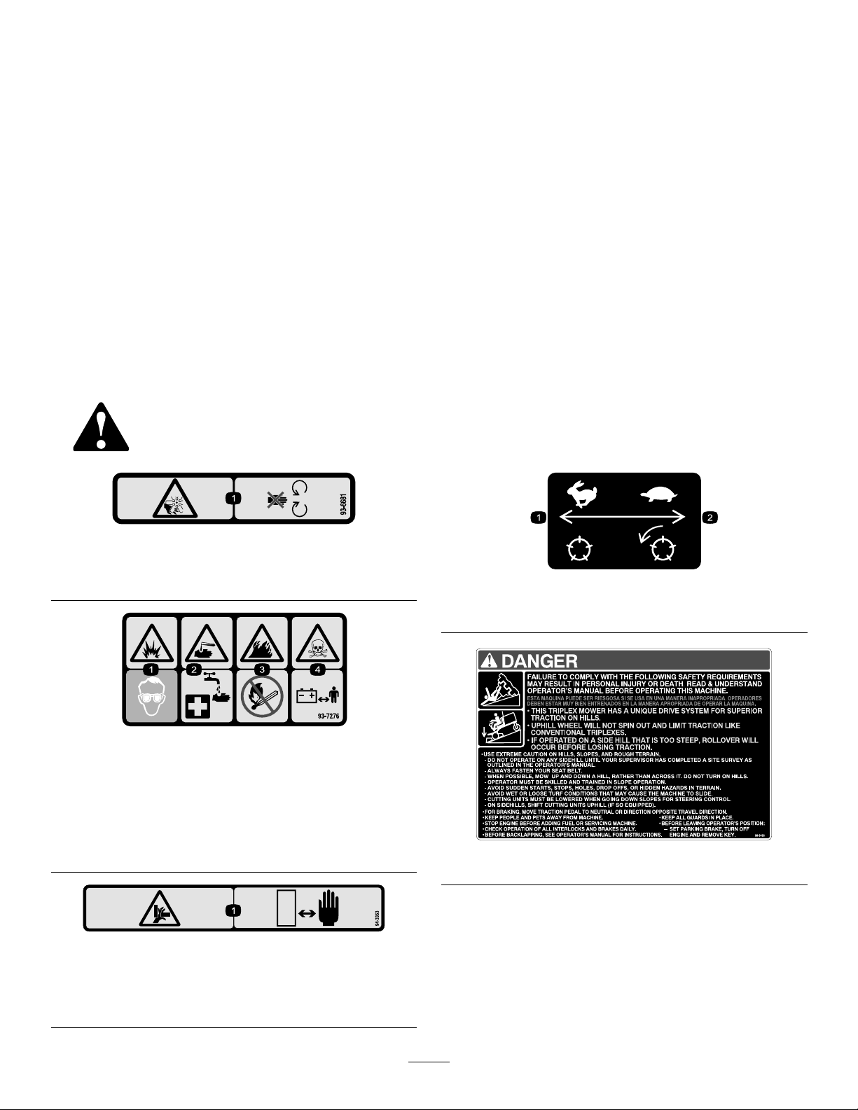
2
93-6681
1.Cutting/dismemberment—hazard,fan-stayawayfrom
movingparts.
93-7276
1.Explosionhazard—weareyeprotection.
2.Causticliquid/chemicalburnhazard—toperformrstaid,
ushwithwater.
3.Firehazard—nore,openames,orsmoking.
4.Poisonhazard—keepchildrenasafedistancefromthe
battery.
99-3444
1.Reelspeed—fast
2.Reelspeed—slow
99-3496
94-3353
Model03207only
1.Crushinghazardofhand—keepyourhandsasafedistance
away.
8
Page 9
104-5181
CEonly
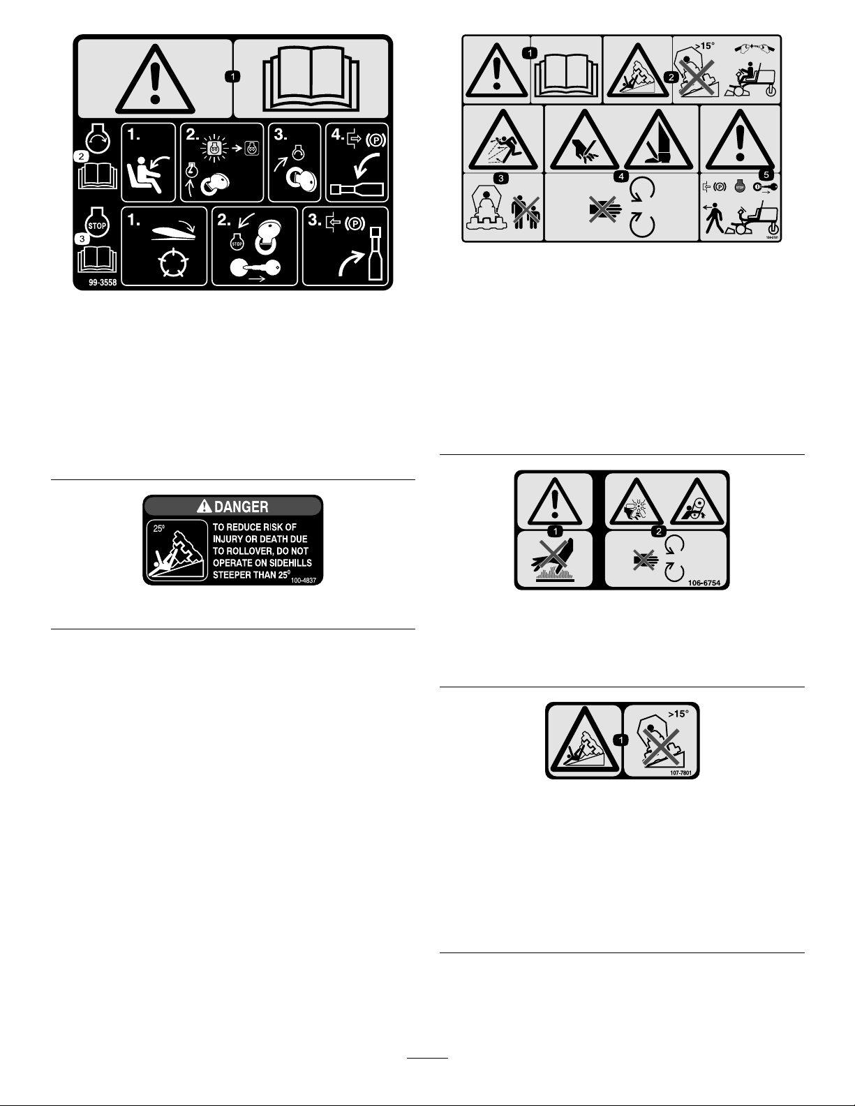
99-3558
CEonly
1.Warning—readtheOperator’sManual.
2.Tostarttheengine,sitontheseatandrotatetheignition
keytoOn/Preheatuntiltheglowplugindicatorlightgoes
out.Rotatethekeytostartanddisengagetheparking
brake.ReadtheOperator’sManualforfurtherinstructions.
3.Tostoptheengine,disengagethecuttingunits,rotatethe
ignitionkeytoOff,andremovethekey .Engagetheparking
brake.ReadtheOperator’sManualforfurtherinstructions.
100-4837
1.Warning—readtheOperator’sManual.
2.Tippinghazard—donotdriveonslopesgreaterthan15
degreesand,iftherollbarisinstalled,weartheseatbelt.
3.Thrownobjecthazard—keepbystandersasafedistance
fromthemachine.
4.Cuttinghazardofhandorfoot—stayawayfrommoving
parts.
5.Warning—locktheparkingbrake,stoptheengine,and
removetheignitionkeybeforeleavingthemachine.
106-6754
1.Warning—donottouchthehotsurface.
2.Cutting/dismembermenthazard,fanandentanglement
hazard,belt—stayawayfrommovingparts.
107-7801(CEonly)
Thissafetydecalincludesaslopewarningrequired
onthemachineforcompliancetotheEuropeanLawn
MowerSafetyStandardEN836:1997.Theconservative
maximumslopeanglesindicatedforoperationof
thismachineareprescribedbyandrequiredbythis
standard.
1.Tippinghazard—donotdriveonslopesgreaterthan15
degrees.
9
Page 10
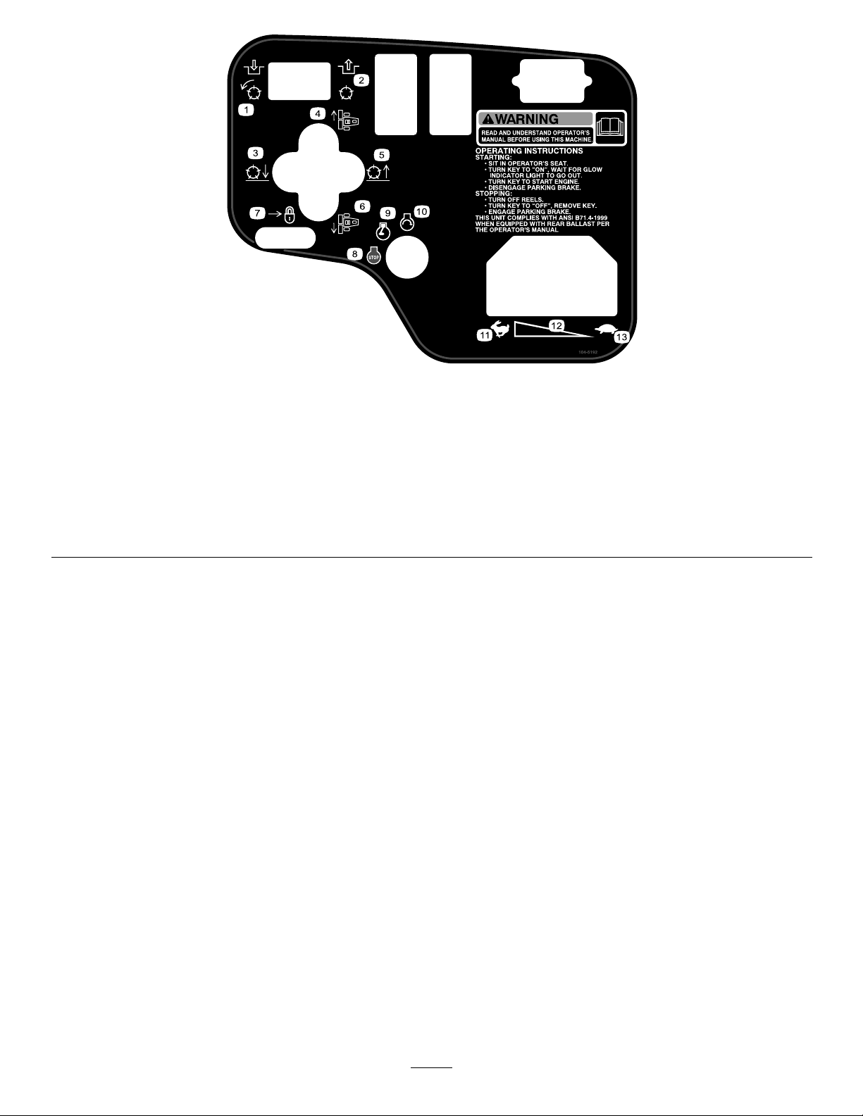
104-5192
Model03207only
1.Engagethepowertakeoff
(PTO).
2.Disengagethepowertake
off(PTO).
3.Lowerthecuttingunits.7.Moverearwardtolockthe
4.Movethecuttingunitsto
theright.
5.Raisethecuttingunits.9.Engine—run
6.Movethecuttingunitsto
theleft.
liftlever.
8.Engine—stop
13.Slow
10.Engine—start
11.Fast
12.Continuousvariablesetting
10
Page 11
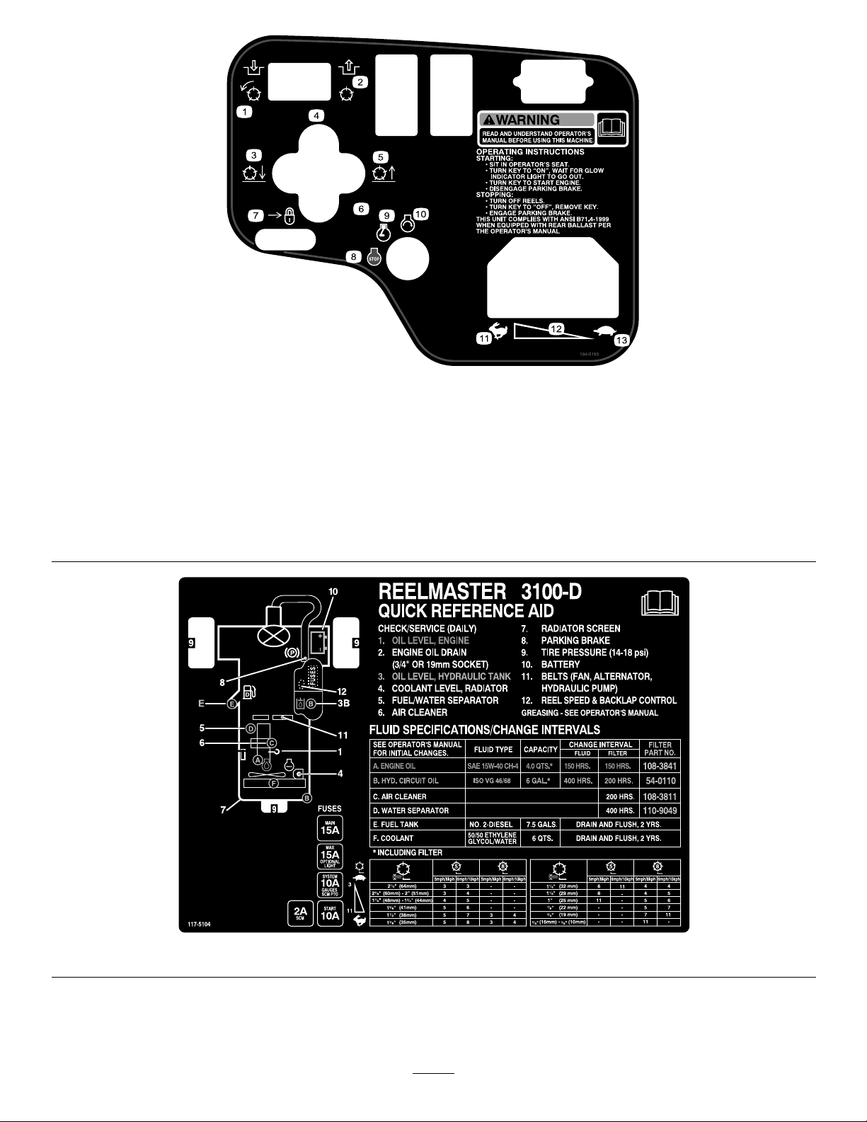
104-5193
Model03206only
1.Engagethepowertakeoff
(PTO).
2.Disengagethepowertake
off(PTO).
3.Lowerthecuttingunits.7.Moverearwardtolockthe
4.Movethecuttingunitsto
theright.
5.Raisethecuttingunits.9.Engine—run
6.Movethecuttingunitsto
theleft.
liftlever.
8.Engine—stop
13.Slow
10.Engine—start
11.Fast
12.Continuousvariablesetting
117-5104
11
Page 12

BatterySymbols
Someorallofthesesymbolsareonyourbattery
1.Explosionhazard
2.Nore,opename,or
smoking.
3.Causticliquid/chemical
burnhazard
4.Weareyeprotection9.Flusheyesimmediately
5.ReadtheOperator's
Manual.
6.Keepbystandersasafe
7.Weareyeprotection;
8.Batteryacidcancause
10.Containslead;donot
distancefromthebattery .
explosivegasescan
causeblindnessandother
injuries
blindnessorsevereburns.
withwaterandgetmedical
helpfast.
discard.
12
Page 13

Setup
LooseParts
Usethechartbelowtoverifythatallpartshavebeenshipped.
ProcedureDescription
1
2
3
4
5
6
7
8
9
Frontwheelassemblies2
Rearwheelassembly1
Steeringwheel
Steeringwheelcap
Largewasher1
Jamnut1
Screw
Electrolyte
Inclinometer1
Lockbracket1
Rivet2
Washer1
Screw,1/4x2inches
Locknut,1/4inch
Exhaustguard1
Self-tappingscrew
Rollbarassembly1
Flangeheadbolts4
Locknuts4
Hoseclamp1
Liftarms
Pivotrod2
Bolt(5/16x7/8inch)
Nopartsrequired
Qty.
A/R
Use
Installthewheels.
1
1
Installthesteeringwheel.
1
Activate,charge,andconnectthe
battery.
Checktheangleindicator.
InstalltheHoodLatch(CE).
1
1
4
2
2
–
InstalltheExhaustGuard(CE).
Installtherollbar .
Installthefrontliftarms.(Partssupplied
intheLiftArmKit.)
Installthecarrierframestothecutting
units.
10
11
12
Nopartsrequired
Nopartsrequired
Nopartsrequired
13
–
–
–
Mountthecuttingunits.
Mountthecuttingunitdrivemotors.
Adjusttheliftarms.
Page 14
MediaandAdditionalParts
Description
Decal,CE
Ignitionkey2
Operator'sManual
EngineOperator'sManual
PartsCatalog
OperatorTrainingMaterial
Pre-deliverychecklist1
Certicateofcompliance
Note:Determinetheleftandrightsidesofthemachine
fromthenormaloperatingposition.
1
InstallingtheWheels
Partsneededforthisprocedure:
2Frontwheelassemblies
1Rearwheelassembly
Qty.
6
1
1
1Usetolookupandorderparts.
1
1
AfxtothemachineovercorrespondingEnglishdecals
forEuropeancompliance.
Starttheengine.
Readbeforeoperatingthemachine.
Viewbeforeoperatingthemachine.
Checktoensurethatthemachinehasbeenproperlyset
up.
EnsureCEcompliance.
2
InstallingtheSteeringWheel
Partsneededforthisprocedure:
1
Steeringwheel
1
Steeringwheelcap
1Largewasher
1Jamnut
1
Screw
Use
Procedure
1.Mountawheelassemblyontoeachwheelhub(valve
stemoutward).
Important:Thereartirehasanarrowerrim
thanthefronttires.
2.Installlugnutsandtorqueto45to65ft-lb(61to
88N-m).
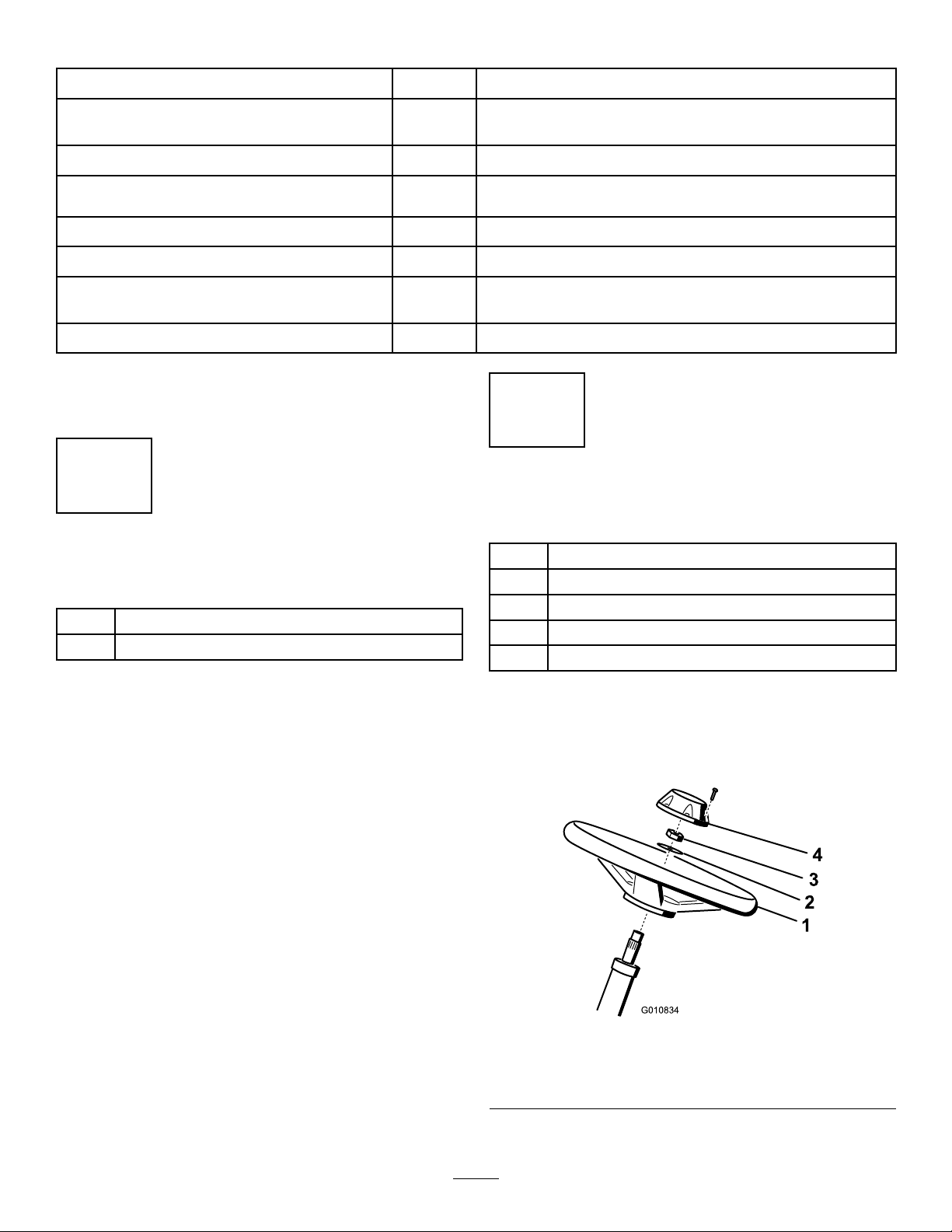
Procedure
1.Slidethesteeringwheelontothesteeringshaft
Figure3).
(
Figure3
1.Steeringwheel
2.Washer
2.Slidethewasherontothesteeringshaft(Figure3).
3.Jamnut
4.Cap
14
Page 15

3.Securethesteeringwheeltotheshaftwithajam
nutandtightenitto20to26ft-lb(27to35N-m)
(Figure3).
4.Installthecaptothesteeringwheelandsecureit
withascrew(
Figure3).
3
Activating,Charging,and
ConnectingtheBattery
Partsneededforthisprocedure:
Electrolyte
A/R
Procedure
WARNING
CALIFORNIA
Proposition65Warning
Batteryposts,terminals,andrelated
accessoriescontainleadandleadcompounds,
chemicalsknowntotheStateofCalifornia
tocausecancerandreproductiveharm.
W ash hands after handling .
Note:Ifthebatteryisnotlledwithelectrolyteor
activated,bulkelectrolytewith1.260specicgravity
mustbepurchasedfromalocalbatterysupplyoutlet
andaddedtothebattery.
DANGER
Batteryelectrolytecontainssulfuricacidwhichisa
deadlypoisonandcausessevereburns.
•Donotdrinkelectrolyteandavoidcontactwith
skin,eyes,orclothing.Wearsafetyglassesto
shieldyoureyesandrubberglovestoprotect
yourhands.
Figure4
1.Batterycover
4.Removethellercapsfromthebatteryandslowly
lleachcelluntilelectrolyteisjustabovetheplates.
5.Installthellercapsandconnecta3to4ampbattery
chargertothebatteryposts.Chargethebatteryata
rateof3to4ampsfor4to8hours.
WARNING
Chargingthebatteryproducesgassesthatcan
explode.
•Keepsparksandamesawayfrombattery.
•Neversmokenearthebattery.
6.Whenthebatteryischarged,disconnectthecharger
fromtheelectricaloutletandbatteryposts.
7.Removethellercaps.Slowlyaddelectrolyteto
eachcelluntilthelevelisuptothellring.Install
thellercaps.
Important:Donotoverllthebattery.
Electrolytewilloverowontootherpartsofthe
machineandseverecorrosionanddeterioration
willresult.
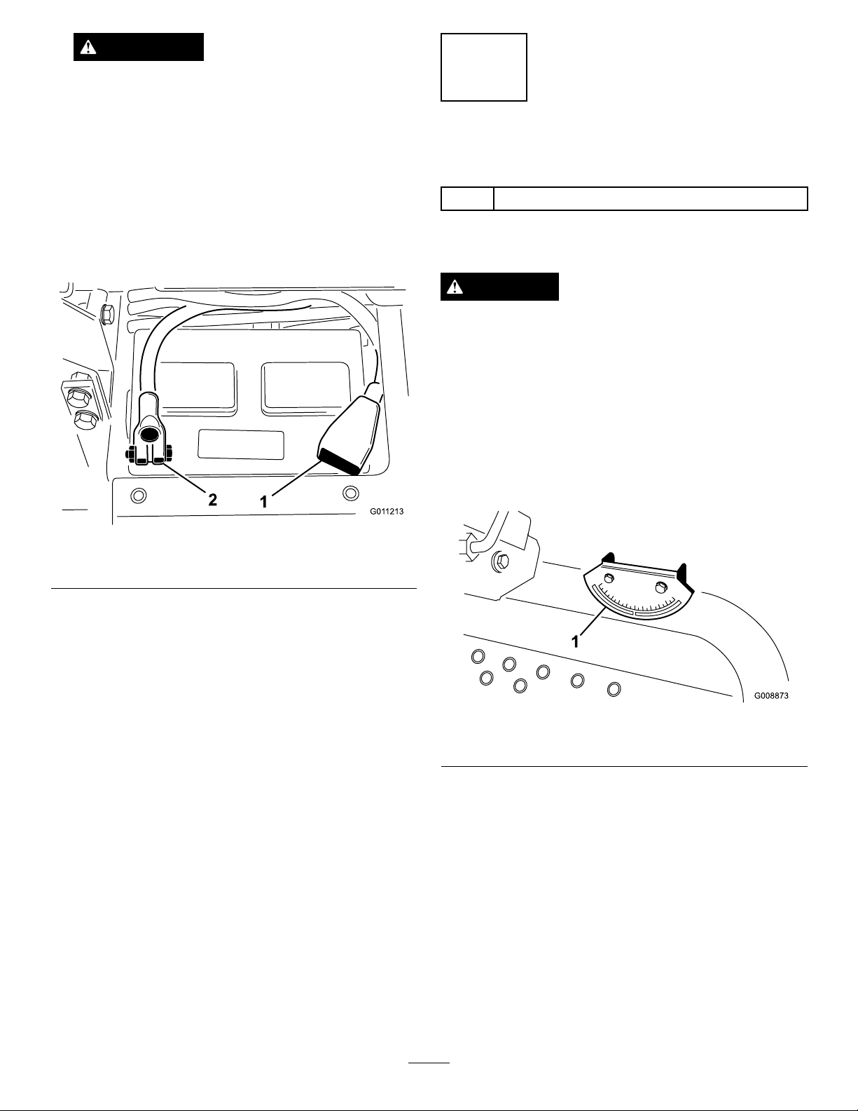
8.Installthepositivecable(red)tothepositive(+)
terminalandthenegativecable(black)tothe
negative(–)terminalofthebatteryandsecurethem
withboltsandnuts(
positive(+)terminalisallofthewayontothepost
andthecableispositionedsnugtothebattery.The
cablemustnotcontactthebatterycover.
Figure5).Makesurethatthe
•Fillthebatterywherecleanwaterisalways
availableforushingtheskin.
1.Purchasebulkelectrolytewith1.260specicgravity
fromalocalbatterysupplyoutlet.
2.Openthehood.
3.Removethebatterycover(Figure4).
15
Page 16
WARNING
Incorrectbatterycableroutingcoulddamage
thetractorandcablescausingsparks.Sparks
cancausethebatterygassestoexplode,
resultinginpersonalinjury.
4
CheckingtheAngleIndicator
•Alwaysdisconnectthenegative(black)
batterycablebeforedisconnectingthe
positive(red)cable.
•Alwaysconnectthepositive(red)battery
cablebeforeconnectingthenegative(black)
cable.
Figure5
1.Positive(+)batterycable2.Negative(–)batterycable
Partsneededforthisprocedure:
1Inclinometer
Procedure
DANGER
Toreduceriskofinjuryordeathduetorollover,do
notoperatethemachineonsidehillssteeperthan
25º.
1.Parkthemachineonaat,levelsurface.
2.Verifythatthemachineislevelbyplacingahand
heldinclinometer(suppliedwiththemachine)on
theframecrossrail,bythefueltank(
inclinometershouldreadzerodegreeswhenviewed
fromtheoperator’sposition.
Figure6).The
Important:Ifthebatteryiseverremoved,make
surethatthebatteryclampboltsareinstalled
withtheboltheadspositionedonthebottom
sideandthenutsonthetopside.Iftheclamp
boltsarereversed,theymayinterferewiththe
hydraulictubeswhenshiftingthecuttingunits.
9.CoatbothbatteryconnectionswithGrafo112X
(skinover)grease,ToroPartNo.505-47,petroleum
jelly,orlightgreasetopreventcorrosion.
10.Slidetherubberbootoverthepositiveterminalto
preventapossibleshortfromoccurring.
11.Installthebatterycover.
Figure6
1.Angleindicator
3.Iftheinclinometerdoesnotreadzerodegrees,
movethemachinetoalocationwhereazerodegree
readingisobtained.Theangleindicator,mountedon
themachine,shouldnowreadzerodegreesaswell.
4.Iftheangleindicatordoesnotreadzerodegrees,
loosenthetwoscrewsandnutssecuringtheangle
indicatortothemountingbracket,adjustthe
indicatortoobtainazerodegreereading,andtighten
thebolts.
16
Page 17
5
G012628
1
2
G012629
1
2
G012630
1
G012631
1
2
3
InstallingtheHoodLatch(CE
Only)
Partsneededforthisprocedure:
1Lockbracket
2Rivet
1Washer
1
Screw,1/4x2inches
1
Locknut,1/4inch
Procedure
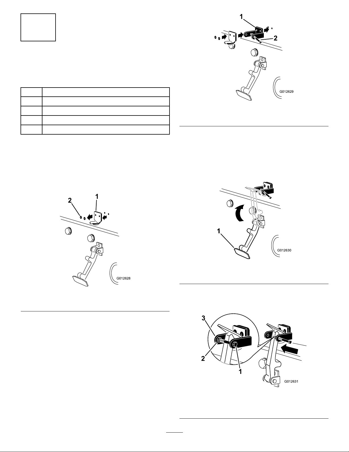
1.Unhookthehoodlatchfromthehoodlatchbracket.
2.Removethe(2)rivetssecuringthehoodlatchbracket
tothehood(Figure7).Removethehoodlatch
bracketfromthehood.
Figure8
1.CElockbracket
2.Boltandnutassembly
4.Alignthewasherswiththeholesontheinsideofthe
hood.
5.Rivetthebracketsandthewasherstothehood
(Figure8).
6.Hookthelatchontothehoodlatchbracket
Figure9).
(
Figure9
1.Hoodlatch
Figure7
1.Hoodlatchbracket2.Rivets
7.Screwtheboltintotheotherarmofhoodlock
brackettolockthelatchinposition(Figure10).
Tightenboltsecurelybutdonottightennut.
3.Whilealigningthemountingholes,positiontheCE
lockbracketandthehoodlatchbracketontothe
hood.Thelockbracketmustbeagainstthehood
(Figure8).Donotremoveboltandnutassembly
fromthelockbracketarm.
1.Bolt
2.Nut
Figure10
3.Armofhoodlockbracket
17
Page 18
6
7
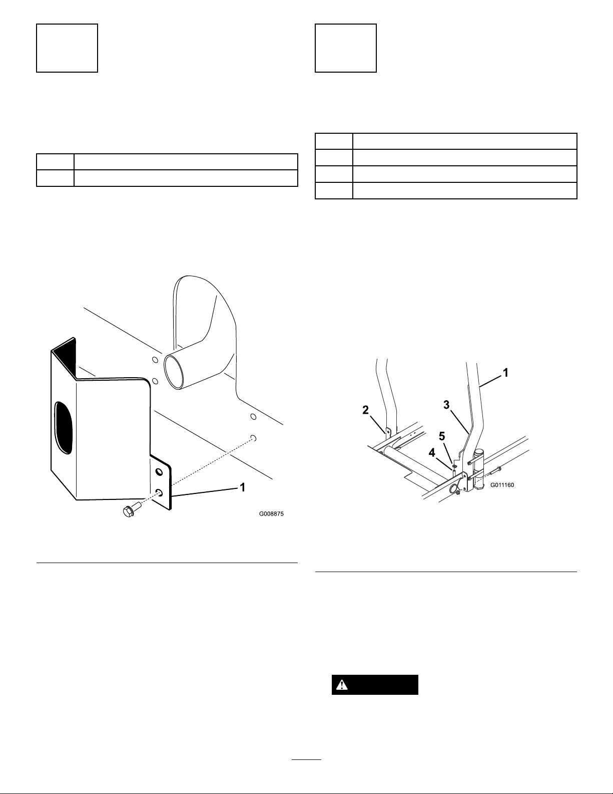
InstallingtheExhaustGuard
(CEOnly)
Partsneededforthisprocedure:
1Exhaustguard
4
Self-tappingscrew
Procedure
1.Positiontheexhaustguardaroundthemuferwhile
aligningthemountingholeswiththeholesinthe
frame(
Figure11).
InstallingtheRollBar
Partsneededforthisprocedure:
1Rollbarassembly
4Flangeheadbolts
4Locknuts
1Hoseclamp
Procedure
Important:Neverweldormodifyarollover
protectionsystem(ROPS).Replaceadamaged
ROPS,donotrepairorrevise.Anyalterationofa
ROPSmustbeapprovedbythemanufacturer.
1.Lowertherollbarontothetractionunitmounting
brackets,aligningthemountingholes.Ensurethat
theventtubeontherollbarisontheleftsideof
themachine(
Figure12).
Figure11
1.Exhaustguard
2.Securetheexhaustguardtotheframewith4
self-tappingscrews(
Figure11).
Figure12
1.ROPS
2.Mountingbracket5.Hoseclamp
3.Venttube
2.Secureeachsideoftherollbartothemounting
bracketswith2angeheadboltsandlocknuts
(
Figure12).Torquethefastenersto60ft-lb(81
N-m).
3.Securethefuellineventhosetotheventtubeonthe
rollbarwiththehoseclamp.
4.Fuellineventtubehose
CAUTION
Youmustconnectthefuellineventhosetothe
venttubepriortostartingtheengineorfuelwill
owfromthehose.
18
Page 19

8
InstallingtheFrontLiftArms
Partsneededforthisprocedure:
2
Liftarms
2Pivotrod
2
Bolt(5/16x7/8inch)
Procedure
1.Removethe2boltsthatsecuretheliftarmpivot
shaftlinktotheliftarmpivotshafts,andremoveand
retainthepivotshaftlinkandbolts(
Figure13).
4.Inserttheliftarmsontotheliftarmpivotshafts
(Figure15),andsecureeachwithaliftarmpivot
shaftlinkandboltspreviouslyremoved.
Note:Torquetheboltsto70ft-lb(95N-m).
Figure15
1.Liftarm,right4.Liftcylinder
2.Retainingring
3.Liftarm,left
5.Spacers(2)
6.Mountingpin
Figure13
1.Liftarm,pivotshaftlink2.Liftarmpivotshaft
2.Insertapivotrodintoeachliftarmandalignthe
mountingholes(Figure14).
Figure14
1.Liftarm
2.Pivotrod
5.Removetherearretainingringssecuringthe
mountingpinstoeachendoftheliftcylinder.
6.Securetherightendoftheliftcylindertotheright
liftarmwithapinand2spacers((
Secureitwitharetainingring.
7.Securetheleftendoftheliftcylindertotheleftlift
armwithapin.Secureitwitharetainingring.
Figure15),).
9
InstallingtheCarrierFrames
totheCuttingUnits
NoPartsRequired
Procedure
1.Removethecuttingunitsfromthecartons.Adjust
themasdescribedintheCuttingUnitOperator’ s
Manual.
2.Positionafrontcarrierframe(Figure16)ontoeach
frontcuttingunit.
3.Securethepivotrodstotheliftarmswith2bolts
(5/16x7/8inch).
19
Page 20

Figure16
1.Frontcarrierframe
3.Securethemountinglinkstothefrontcarrierframes
asfollows:
•Securethefrontmountinglinkstothemiddle
carrierframeholeswithabolt(3/8x2-1/4
inch),2atwashers,andalocknut,asshownin
Figure17.Positionawasheroneachsideofthe
linkwhenmounting.Torquethefastenersto31
ft-lb(42N-m).
•Securetherearmountinglinkstothemiddle
carrierframeholeswithabolt(3/8x2-1/4
inch),2atwashers,andalocknut,asshownin
Figure17.Positionawasheroneachsideofthe
linkwhenmounting.Torquethefastenersto31
ft-lb(42N-m).
4.Positiontherearcarrierframe(Figure18)ontothe
rearcuttingunit.
Figure18
1.Rearcarrierframe
5.Securethemountinglinkstotherearcarrierframe
asfollows:
•Securethefrontmountinglinkstothecarrier
frameholeswithabolt(3/8x2-1/4inch),2at
washers,andalocknut,asshownin
Figure19.
Positionawasheroneachsideofthelinkwhen
mounting.Torquethefastenersto31ft-lb(42
N-m).
•Securetherearmountinglinkstotherearcarrier
frameholeswithabolt(3/8x2-1/4inch),2at
washers,andalocknut,asshownin
Figure19.
Positionawasheroneachsideofthelinkwhen
mounting.Torquethefastenersto31ft-lb(42
N-m).
1.Frontcarrierframe
2.Frontmountinglink
3.Rearmountinglink
Figure17
20
Page 21

Figure19
3.Greasealltheliftarmandcarrierframepivotpoints.
Important:Ensurethatthehosesarefreeof
twistsorsharpbendsandthattherearcutting
unithosesareroutedasshowin(
Raisethecuttingunitsandshiftthemtotheleft
(Model03170).Therearcuttingunithosesmust
notcontacttractioncablebracket.Reposition
thettingsand/orhoses,ifnecessary.
Figure21).
1.Rearcarrierframe
2.Frontmountinglink
3.Rearmountinglink
10
MountingtheCuttingUnits
NoPartsRequired
Procedure
1.Slideathrustwasherontoeachfrontliftarmpivot
rod.
2.Slidethecuttingunitcarrierframeontothepivotrod
andsecureitwithalynchpin(
Note:Onrearcuttingunit,positionthethrust
washerbetweentherearofthecarrierframeand
thelynchpin.
Figure20).
Figure21
4.Routeatipperchainupthroughtheslotontheend
ofeachcarrierframe.Securethetipperchaintothe
topofthecarrierframewithabolt,awasher,anda
locknut(
Figure22).
Figure20
1.Thrustwasher3.Lynchpin
2.Carrierframe
Figure22
1.Tipperchain
21
Page 22

11
MountingtheCuttingUnit
DriveMotors
NoPartsRequired
Procedure
1.Positionthecuttingunitsinfrontoftheliftarm
pivotrods.
2.RemovetheweightandO-ring(
insideendoftherighthandcuttingunit.
Figure23
1.O-ring
2.Weight
3.Mountingbolts
Figure23)fromthe
Figure24
1.O-ring
6.Mountthemotortothedriveendofthecutting
unit,andsecureitwithtwocapscrewsprovidedwith
cuttingunit(Figure24).
2.Reelmotor
12
AdjustingtheLiftArms
NoPartsRequired
Procedure
1.Starttheengine,raisetheliftarms,andcheckto
ensurethattheclearancebetweeneachliftarmand
theoorplatebracketis0.18to0.32inches(5to
8mm)(Figure25).
3.Removetheplugfromthebearinghousingonthe
outsideendoftherighthandcuttingunitandinstall
theweightsandgasket.
4.Removetheshippingplugfromthebearinghousings
ontheremainingcuttingunits.
5.InserttheO-ring(suppliedwiththecuttingunit)on
theangeofthedrivemotor(
Figure24).
Figure25
Cuttingunitsremovedforclarity
1.Liftarm3.Clearance
2.Floorplatebracket
22
Page 23

Note:Iftheclearanceisnotinthisrange,adjustthe
cylinderasfollows:
A.Backoffthestopboltsandadjustthecylinderto
attaintheclearance(Figure26).
Figure26
1.Stopbolt3.Clearance
2.Liftarm
B.Backoffthejamnutonthecylinder(Figure27).
bumperstrapis0.02to0.10inches(0.51to2.54
mm)(
Figure28).
Figure28
1.Wearbar2.Bumperstrap
Iftheclearanceisnotinthisrange,adjusttherear
cylinderasfollows:
A.Lowerthecuttingunitsandbackoffthejamnut
onthecylinder(Figure29).
Figure27
1.Frontcylinder2.Jamnut
C.Removethepinfromtherodendandrotatethe
clevis.
D.Installthepinandchecktheclearance.
E.RepeatstepsAthroughDifnecessary.
F.Tightentheclevisjamnut.
Note:Iftherearliftarmclunksduringtransport,
reducetheclearance.
2.Checktoensurethattheclearancebetweeneachlift
armandstopboltis0.005to0.040inches(0.13to
1.02mm)(
Figure26).
Note:Iftheclearanceisnotinthisrange,adjustthe
stopboltstoattainclearance.
Figure29
1.Rearcylinder2.Adjustingnut
B.Graspthecylinderrodclosetothenutwitha
pliersandragandrotatetherod.
C.Raisethecuttingunitsandchecktheclearance.
D.RepeatstepsAthroughCifnecessary.
E.Tightentheclevisjamnut.
Important:Lackofclearanceatthefrontstopsor
therearwearbarcoulddamagetheliftarms.
3.Starttheengine,raisetheliftarms,andcheckto
ensurethattheclearancebetweenthewearstrap
onthetopoftherearcuttingunitwearbarandthe
23
Page 24

ProductOverview
TiltSteeringLever
Pullthetiltsteeringlever(Figure30)backtoadjustthe
Controls
steeringwheeltothedesiredposition,thenpushthe
leverforwardtotighten.
IndicatorSlot
Theslotintheoperatorplatform(Figure30)indicates
whenthecuttingunitsareinthecenterposition.
AngleIndicator
Theangleindicator(Figure30)indicatesthesidehill
angleofthemachineindegrees.
IgnitionSwitch
Figure30
1.Forwardtractionpedal4.Tiltsteeringlever
2.Reversetractionpedal5.Indicatorslot
3.Mow/transportslide
6.Angleindicator
TractionPedals
Pressthetractionforwardpedal(Figure30)tomove
forward.Presstractionreversepedal(Figure30)to
movebackwardortoassistinstoppingwhenmoving
forward.Also,allowthepedaltomoveormoveittothe
neutralpositiontostopthemachine.
Mow/TransportSlide
Usingyourheel,movethemow/transportslide
(Figure30)tothelefttotransportandtotherightto
mow .Thecuttingunitswillonlyoperateinthemow
position.
Important:Themowspeedissetatthefactoryto
6mph(9.7km/h).Itcanbeincreasedordecreased
byadjustingthespeedstopscrew(
Figure31).
Theignitionswitch(Figure32),whichisusedtostart,
stop,andpreheattheengine,hasthreepositions:
Off,On/Preheat,andStart.Rotatethekeytothe
On/Preheatpositionuntiltheglowplugindicatorlight
goesout(approximately7seconds);thenrotatethe
keytotheStartpositiontoengagethestartermotor.
Releasethekeywhentheenginestarts.Thekeywill
moveautomaticallytotheOn/Runposition.Toshutthe
engineoff,rotatethekeytotheOffpositionandremove
thekeyfromtheswitchtopreventaccidentalstarting.
Figure32
1.Throttle
2.Hourmeter
3.Temperaturelight9.Ignitionswitch
4.Oilpressurelight
5.Glowplugindicatorlight1 1.Liftleverlock
6.Alternatorlight
7.Cuttingunitdriveswitch
8.Cuttingunitshiftlever
10.Parkingbrake
1.Speedstopscrew
Figure31
Throttle
Movethethrottle(Figure32)forwardtoincreasethe
enginespeedandrearwardtodecreasetheenginespeed.
24
Page 25

CuttingUnitDriveSwitch
GlowPlugIndicator
Thecuttingunitdriveswitch(Figure32)hastwo
positions:EngageandDisengage.Therockerswitch
operatesasolenoidvalveonthevalvebanktodrivethe
cuttingunits.
HourMeter
Thehourmeter(Figure32)indicatesthetotalhoursof
machineoperation.Thehourmeterstartstofunction
wheneverthekeyswitchisOn.
CuttingUnitShiftLever
Tolowerthecuttingunitstotheground,movethe
cuttingunitshiftlever(Figure32)forward.Thecutting
unitswillnotdropunlesstheengineisrunning,and
theywillnotoperateintheraisedposition.Toraisethe
cuttingunits,pulltheshiftleverrearwardtotheRaise
position.
Movethelevertotherightorlefttomovethecutting
unitsinthesamedirection.Thisshouldonlybedone
whenthecuttingunitsareraisedoriftheyareonthe
groundandthemachineismoving(Model03170only).
Theglowplugindicatorlight(Figure32)willglowwhen
theglowplugsareoperating.
ParkingBrake
Whenevertheengineisshutoff,engagetheparking
brake(Figure32)topreventaccidentalmovementofthe
machine.Toengagetheparkingbrake,pulluponthe
lever.Theenginewillstopifyoupressthetractionpedal
withtheparkingbrakeengaged.
LiftLeverLock
Movetheliftleverlock(Figure32)rearwardtoprevent
thecuttingunitsfromdropping.
ReelSpeedControl
Thereelspeedcontrolislocatedundertheconsole
cover(
(reelspeed),rotatethereelspeedcontrolknobtothe
appropriateheight-of-cutsettingandmowerspeed.
RefertoSelectingtheClipRate.
Figure33).Toobtainthedesiredcliprate
Note:Theleverdoesnothavetobeheldintheforward
positionwhilethecuttingunitsarelowered.
DANGER
Shiftingthecuttingunitsdownhilldecreases
machinestability .Thiscouldcausearollover,
whichmayresultinpersonalinjuryordeath.
Shiftthecuttingunitsuphillwhileonasidehill.
EngineCoolantTemperatureWarning
Light
Thetemperaturewarninglight(Figure32)glowsifthe
enginecoolanttemperatureishigh.Ifthetractionunitis
notstoppedandthecoolanttemperaturerisesanother
10°F,theenginewillkill.
OilPressureWarningLight
Theoilpressurewarninglight(Figure32)glowsifthe
engineoilpressuredropsbelowasafelevel.
AlternatorLight
Thealternatorlight(Figure32)shouldbeoffwhenthe
engineisrunning.Ifitison,thechargingsystemshould
becheckedandrepairedasnecessary.
Figure33
1.Reelspeedcontrol2.Backlapcontrol
BacklapControl
Thebacklapcontrolislocatedundertheconsolecover
(Figure33).RotatetheknobtoRforbacklappingandto
Fformowing.Donotchangetheknobpositionwhile
thereelsarerotating.
25
Page 26

FuelGauge
Thefuelgauge(Figure34)registerstheamountoffuel
inthetank.
Figure34
enhanceandexpanditscapabilities.Contactyour
AuthorizedServiceDealerorDistributororgoto
www.Toro.comforalistofallapprovedattachments
andaccessories.
1.Foreandaftlever
2.Fuelgauge
ForeandAftSeatAdjustments
Movethelever(Figure34)onthesideoftheseat
outward,slidetheseattothedesiredposition,and
releasethelevertolocktheseatintoposition.
Specications
Note:Specicationsanddesignaresubjecttochange
withoutnotice.
TransportWidth
Widthofcut72"(183cm)or85"(216cm)
Length
Height
Netweight*1860lbs.(844kg)
Fueltankcapacity
GroundspeedMow:0-6mph(0-10km/h);
*Withcuttingunitsanduids
80"(203cm)in72"
(183cm)widthofcut
92"(234cm)in85"(216
cm)widthofcut
widthofcut
93"(248cm)
71"(180cm)withROPS
7.5gallons(28liters).
Transport:0-9mph(0-14
km/h).Reverse:0-4mph.(0-6
km/h).
Attachments/Accessories
AselectionofToroapprovedattachmentsand
accessoriesareavailableforusewiththemachineto
26
Page 27

Operation
Note:Determinetheleftandrightsidesofthe
machinefromthenormaloperatingposition.
CheckingtheEngineOilLevel
ServiceInterval:Beforeeachuseordaily
Theengineisshippedwithoilinthecrankcase;
however,theoillevelmustbecheckedbeforeandafter
theengineisrststarted.
Crankcasecapacityisapproximately4qt.(2.8l)with
thelter.
Usehigh-qualityengineoilthatmeetsthefollowing
specications:
•APIClassicationLevelRequired:CH-4,CI-4or
higher.
•Preferredoil:SAE15W-40(above0ºF(-17ºC))
3.Pushthedipstickdownintothedipsticktubeand
ensurethatitisseatedfully,thenpullthedipstick
outandchecktheoillevel.
4.Iftheoillevelislow ,removetheoilllcap
Figure36)andgraduallyaddsmallquantitiesofoil,
(
checkingthelevelfrequently ,untilthelevelreaches
theFullmarkonthedipstick.
Figure36
1.Oilllcap
•Alternateoil:SAE10W -30or5W -30(all
temperatures)
Note:ToroPremiumEngineoilisavailablefroma
distributorineither15W-40or10W-30viscosity.See
thepartscatalogforpartnumbers.
Note:Thebesttimetochecktheengineoiliswhen
theengineiscoolbeforeithasbeenstartedforthe
day.Ifithasalreadybeenrun,allowtheoiltodrain
backdowntothesumpforatleast10minutesbefore
checking.Iftheoillevelisatorbelowthe“add”mark
onthedipstick,addoiltobringtheoilleveltothe“full”
mark.Donotoverll.Iftheoillevelisbetweenthe
“full”and“add”marks,youdonotneedtoaddoil.
1.Positionthemachineonalevelsurface.
2.Removethedipstick(
acleanrag.
Figure35)andwipeitwith
5.Installtheoilllcapandclosethehood.
Important:Besuretokeeptheengineoillevel
betweentheupperandlowerlimitsontheoil
gauge.Enginefailuremayoccurasaresultof
overllingorunderllingtheengineoil.
FillingtheFuelTank
DANGER
Undercertainconditions,dieselfuelandfuel
vaporsarehighlyammableandexplosive.Are
orexplosionfromfuelcanburnyouandothersand
cancausepropertydamage.
•Useafunnelandllthefueltankoutdoors,in
anopenarea,whentheengineisoffandiscold.
Wipeupanyfuelthatspills.
•Donotllthefueltankcompletelyfull.Add
fueltothefueltankuntilthelevelis1/4to1/2
inch(6to13mm)belowthebottomoftheller
neck.Thisemptyspaceinthetankallowsthe
fueltoexpand.
•Neversmokewhenhandlingfuel,andstay
awayfromanopenameorwherefuelfumes
maybeignitedbyaspark.
•Storefuelinaclean,safety-approvedcontainer
Figure35
1.Dipstick
27
andkeepthecapinplace.
Useonlyclean,freshdieselfuelorbiodieselfuelswith
low(<500ppm)orultralow(<15ppm)sulfurcontent.
Page 28

Theminimumcetaneratingshouldbe40.Purchase
fuelinquantitiesthatcanbeusedwithin180daysto
ensurefuelfreshness.
Thefueltankcapacityisapproximately7.5gallons(28
liters).
3.Fillthetanktothebottomofthellerneck.Do
notoverll.
4.Installthecap.
5.Wipeupanyfuelthatmayhavespilled.
Usesummergradedieselfuel(No.2-D)attemperatures
above20°F(-7°C)andwintergrade(No.1-DorNo.
1-D/2-Dblend)belowthattemperature.Usingwinter
gradefuelatlowertemperaturesprovidesalowerash
pointandcoldowcharacteristicswhichwillease
startingandreducepluggingofthefuellter.
Useofsummergradefuelabove20°F(-7°C)will
contributetowardlongerfuelpumplifeandincreased
powercomparedtowintergradefuel.
BiodieselReady
Thismachinecanalsouseabiodieselblendedfuel
ofuptoB20(20%biodiesel,80%petrodiesel).The
petrodieselportionshouldbeloworultralowsulfur.
Observethefollowingprecautions:
•Thebiodieselportionofthefuelmustmeet
specicationASTMD6751orEN14214.
•TheblendedfuelcompositionshouldmeetASTM
D975orEN590.
•Paintedsurfacesmaybedamagedbybiodiesel
blends.
•UseB5(biodieselcontentof5%)orlesserblends
incoldweather.
CheckingtheCoolingSystem
ServiceInterval:Beforeeachuseordaily
Cleandebrisoffoftheradiatorandtheoilcoolerdaily
Figure38).Cleantheradiatorhourlyifconditionsare
(
extremelydustyanddirty;refertoCleaningtheEngine
CoolingSystem.
Figure38
1.Accesspanel
2.Radiator
3.Oilcooler
•Monitorseals,hoses,gasketsincontactwithfuelas
theymaybedegradedovertime.
•Fuellterpluggingmaybeexpectedforatimeafter
convertingtobiodieselblends.
•Contactadistributorformoreinformationon
biodieselblendedfuel.
1.Cleantheareaaroundthefueltankcap(
Figure37
1.Fueltankcap
Figure37).
2.Removethefueltankcap.
Thecoolingsystemislledwitha50/50solutionof
waterandpermanentethyleneglycolanti-freeze.Check
thecoolantlevelatthebeginningofeachdaybefore
startingtheengine.
Thecapacityofthecoolingsystemisapproximately
6qt(5.7l).
CAUTION
Iftheenginehasbeenrunning,thepressurized,
hotcoolantcanescapeandcauseburns.
•Donotopentheradiatorcapwhentheengine
isrunning.
•Usearagwhenopeningtheradiatorcap,and
openthecapslowlytoallowsteamtoescape.
1.Checkthecoolantlevelintheexpansiontank
(Figure39).
28
Page 29

PourPoint,ASTMD97-34°Fto-49°F
IndustrySpecications:
VickersI-286-S(QualityLevel),VickersM-2950-S
(QualityLevel),DenisonHF-0
Note:Manyhydraulicuidsarealmostcolorless,
makingitdifculttospotleaks.Areddyeadditivefor
thehydraulicsystemoilisavailablein2/3oz.(20ml)
bottles.Onebottleissufcientfor4-6U.S.gallons
(15-221)ofhydraulicoil.Orderpartno.44-2500from
anauthorizedTorodistributor.
BiodegradableHydraulicFluid—Mobil224H
Figure39
1.Expansiontank
Note:Withacoldengine,thecoolantlevelshould
beapproximatelymidwaybetweenthemarksonthe
sideofthetank.
2.Ifthecoolantlevelislow ,removetheexpansion
tankcapandreplenishthesystem.Donotoverll.
3.Installtheexpansiontankcap.
CheckingtheHydraulic
System
ServiceInterval:Beforeeachuseordaily—Checkthe
hydraulicuidlevel.
Thehydraulicuidtankislledatthefactorywith
approximately3.5U .S.gallons(13.2l)ofhigh-quality
hydraulicuid.Checkthelevelofthehydraulic
uidbeforetheengineisrststartedanddaily
thereafter.Therecommendedreplacementuid
isT oroPremiumAllSeasonHydraulicFluid
(Availablein5-gallonpailsor55-gallondrums.See
partscatalogorT orodistributorforpartnumbers.)
ToroBiodegradableHydraulicFluid(Availablein5gallon
pailsor55gallondrums.SeepartscatalogoraT oro
distributorforpartnumbers.)
Alternateuid:MobilEAL224H
Thisisvegetable-oilbasedbiodegradableoiltestedand
approvedbyToroforthismodel.Thisuidisnot
asresistanttohightemperaturesasstandarduid,so
installanoilcoolerifrequiredbytheoperatormanual
andfollowrecommendeduidchangeintervalswith
thisuid.Contaminationbymineral–basedhydraulic
uidswillchangethebiodegradabilityandtoxicityof
thisoil.Whenchangingfromstandarduidtothe
biodegradabletype,becertaintofollowtheapproved
ushingprocedure.ContactalocalToroDistributor
fordetails.
1.Positionthemachineonalevelsurface,lowerthe
cuttingunits,andstoptheengine.
2.Cleantheareaaroundthellerneckandcapofthe
hydraulicuidtank(
Figure40)andremovethecap.
Alternateuids:IftheTorouidisnotavailable,other
uidsmaybeusedprovidedtheymeetallthefollowing
materialpropertiesandindustryspecications.Toro
doesnotrecommendusingsyntheticuid.Consultwith
alubricantdistributortoidentifyasatisfactoryproduct.
Note:Torowillnotassumeresponsibilityfordamage
causedbyimpropersubstitutions,souseonlyproducts
fromreputablemanufacturerswhowillstandbehind
theirrecommendation.
HighViscosityIndex/LowPourPointAnti-wearHydraulic
Fluid,ISOVG46
MaterialProperties:
Viscosity,ASTMD445cSt@40°C44to48
ViscosityIndexASTM
D2270
cSt@100°C7.9to8.5
140to160
Figure40
1.Hydraulicuidtankcap
3.Removethedipstickfromthellerneckandwipe
itwithacleanrag.Insertthedipstickintotheller
neck;thenremoveitandchecktheuidlevel.The
uidlevelshouldbewithin1/4inch(6mm)ofthe
markonthedipstick.
29
Page 30

4.Ifthelevelislow ,addtheappropriateuidtoraise
theleveltothefullmark.
5.Installthedipstickandcapontothellerneck.
•Theenginehasceasedrunningduetolackof
fuel.
•Maintenancehasbeenperformeduponthefuel
systemcomponents;e.g.,lterreplaced,etc.
CheckingtheTirePressure
ServiceInterval:Beforeeachuseordaily
Thetiresareover-inatedforshipping.Therefore,
releasesomeoftheairtoreducethepressure.The
properairpressureinthetiresis14to18psi(97to
124kPa).
Note:Maintaintherecommendedpressureinalltires
toensureagoodqualityofcutandpropermachine
performance.
DANGER
Lowtirepressuredecreasesmachinesidehill
stability.Thiscouldcausearollover,whichmay
resultinpersonalinjuryordeath.
Donotunder-inatethetires.
CheckingtheReel-to-Bedknife
Contact
ServiceInterval:Beforeeachuseordaily
Checkthereel-to-bedknifecontactevenifthequalityof
cuthadbeenacceptablepreviously .Theremustbelight
contactacrossthefulllengthofthereelandbedknife;
refertoAdjustingReeltoBedknifeintheCuttingUnit
Operator’sManual.
TorquingtheWheelNuts
StartingtheEngine
1.Ensurethattheparkingbrakeissetandthereel
driveswitchisintheDisengageposition.
2.Removeyourfootfromthetractionpedaland
ensurethatthepedalisintheneutralposition.
3.Movethethrottlelevertothe1/2throttleposition.
4.Insertthekeyintotheswitchandrotateittothe
On/Preheatpositionuntiltheglowplugindicator
lightgoesout(approximately7seconds);thenrotate
thekeytotheStartpositiontoengagethestarter
motor.Releasethekeywhentheenginestarts.
Note:Thekeywillmoveautomaticallytothe
On/Runposition.
Important:Topreventoverheatingofthe
startermotor,donotengagethestarterlonger
than15seconds.After10secondsofcontinuous
cranking,wait60secondsbeforeengagingthe
startermotoragain.
5.Whentheengineisstartedforthersttimeorafter
anoverhauloftheengine,operatethemachinein
forwardandreverseforonetotwominutes.Also
operatetheliftleverandcuttingunitdriveswitchto
ensureproperoperationofallparts.
Note:Turnthesteeringwheeltotheleftandright
tocheckthesteeringresponse,thenshuttheengine
offandcheckforoilleaks,looseparts,andany
othernoticeablemalfunctions.
ServiceInterval:Afterthersthour
Aftertherst10hours
Every200hours
Torquethewheelnutsto45to65ft-lb(61to88N-m).
WARNING
Failuretomaintainpropertorqueofthewheelnuts
couldresultinpersonalinjury.
StartingandStoppingthe
Engine
Youmayneedtobleedthefuelsystemifanyof
thefollowingsituationshaveoccurred(referto
BleedingtheFuelSystem):
•Itistheinitialstartupofanewengine.
CAUTION
Stoptheengineandwaitforallmovingpartsto
stopbeforecheckingforoilleaks,looseparts,
andothermalfunctions.
StoppingtheEngine
MovethethrottlecontroltotheIdleposition,movethe
reeldriveswitchtoDisengage,androtatethestarter
keytoOff.
Note:Removethekeyfromtheswitchtoprevent
accidentalstarting.
BleedingtheFuelSystem
1.Parkthemachineonalevelsurface,andensurethat
thefueltankisatleasthalffull.
2.Unlatchandraisethehood.
30
Page 31

DANGER
CheckingtheInterlockSystem
Undercertainconditions,dieselfuelandfuel
vaporsarehighlyammableandexplosive.A
reorexplosionfromfuelcanburnyouand
othersandcancausepropertydamage.
•Useafunnelandllthefueltankoutdoors,
inanopenarea,whentheengineisoffand
iscold.Wipeupanyspilledfuel.
•Donotllthefueltankcompletelyfull.Add
fueltothefueltankuntilthelevelis1/4to
1/2inch(6to13mm)belowthebottomof
thellerneck.Thisemptyspaceinthetank
allowsthefueltoexpand.
•Neversmokewhenhandlingfuel,andstay
awayfromanopenameorwherefuel
fumesmaybeignitedbyaspark.
•Storefuelinaclean,safety-approved
containerandkeepthecapinplace.
3.Opentheairbleedscrewonthefuelinjectionpump
(Figure41).
ServiceInterval:Beforeeachuseordaily
CAUTION
Ifthesafetyinterlockswitchesaredisconnectedor
damaged,themachinecouldoperateunexpectedly,
causingpersonalinjury.
•Donottamperwiththeinterlockswitches.
•Checktheoperationoftheinterlockswitches
dailyandreplaceanydamagedswitchesbefore
operatingthemachine.
1.Ensurethatallbystandersareawayfromtheareaof
operation,andkeephandsandfeetawayfromthe
cuttingunits.
2.Whilesittingontheseat,theenginemustnotstart
witheitherthecuttingunitswitchengagedorthe
tractionpedalengaged.Correcttheproblemifitis
notoperatingproperly .
3.Whilesittingontheseat,putthetractionpedalin
neutral,disengagetheparkingbrake,andsetthe
cuttingunitswitchintheOffposition.Theengine
shouldstart.Risefromtheseatandslowlypress
thetractionpedal,andtheengineshouldstopin
onetothreeseconds.Correcttheproblemifitis
notoperatingproperly .
Figure41
1.Fuelinjectionpumpbleedscrew
4.TurnthekeyintheignitionswitchtotheOn
position.Theelectricfuelpumpwillbegin
operation,therebyforcingairoutaroundtheair
bleedscrew .
Note:LeavethekeyintheOnpositionuntilasolid
streamoffuelowsoutaroundthescrew .
5.TightenthescrewandturnthekeytoOff.
Note:Normallytheengineshouldstartafterfollowing
thebleedingproceduresabove.However,iftheengine
doesnotstart,airmaybetrappedbetweentheinjection
pumpandtheinjectors;refertoBleedingAirfromthe
Injectors.
Note:Themachineisequippedwithaninterlock
switchontheparkingbrake.Theenginewillstopif
thetractionpedalispressedwiththeparkingbrake
engaged.
TowingtheTractionUnit
Incaseofanemergency,themachinecanbetowedfor
ashortdistance;however,Torodoesnotrecommend
thisasastandardprocedure.
Important:Donottowthemachinefasterthan2
to3mph(3to4km/h)becauseitmaydamage
thedrivesystem.Ifthemachinemustbemoveda
considerabledistance,transportitonatruckor
trailer.
1.Locatethebypassvalveonthepump(Figure42)
androtateit90°.
31
Page 32

Figure42
1.Bypassvalve
2.Beforestartingtheengine,closethebypassvalveby
rotatingit90°(1/4turn).Donotstarttheengine
whilethevalveisopen.
ThedecalontheSCMonlyincludessymbols.Three
LEDoutputsymbolsareshownintheoutputbox.All
otherLEDsareinputs.Thechartbelowidentiesthe
symbols.
Figure43
StandardControlModule
(SCM)
TheStandardControlModuleisapottedelectronic
deviceproducedinaone-size-ts-allconguration.The
moduleusessolidstateandmechanicalcomponents
tomonitorandcontrolstandardelectricalfeatures
requiredforsafeproductoperation.
Themodulemonitorsinputsincludingneutral,parking
brake,PTO ,start,backlap,andhightemperature.The
moduleenergizesoutputsincludingPTO ,Starter,and
ETR(energizetorun)solenoid.
Themoduleisdividedintoinputsandoutputs.Inputs
andoutputsareidentiedbygreenLEDindicators
mountedontheprintedcircuitboard.
Thestartcircuitinputisenergizedby12VDC.All
otherinputsareenergizedwhenthecircuitisclosedto
ground.EachinputhasaLEDthatisilluminatedwhen
thespeciccircuitisenergized.UsetheinputLEDsfor
switchandinputcircuittroubleshooting.
Outputcircuitsareenergizedbyanappropriatesetof
inputconditions.ThethreeoutputsincludePTO,ETR,
andSTART.OutputLEDsmonitorrelaycondition
indicatingthepresenceofvoltageatoneofthree
specicoutputterminals.
Outputcircuitsdonotdetermineoutputdevice
integrity,soelectricaltroubleshootingincludesoutput
LEDinspectionandconventionaldeviceandwire
harnessintegritytesting.Measurethedisconnected
componentimpedance,theimpedancethroughwire
harness(disconnectatSCM),orbytemporarily”test
energizing”thespeciccomponent.
HerearethelogicaltroubleshootingstepsfortheSCM
device.
1.Determinetheoutputfaultyouaretryingtoresolve
(PTO,START,orETR).
2.MovethekeyswitchtotheOnpositionandensure
thattheredpowerLEDisilluminated.
3.MovealltheinputswitchestoensurethatallLEDs
changestate.
4.Positiontheinputdevicesattheappropriate
positiontoachievetheappropriateoutput.Usethe
followinglogiccharttodeterminetheappropriate
inputcondition.
5.IfthespecicoutputLEDisilluminatedwithout
theappropriateoutputfunction,checktheoutput
harness,connections,andcomponent.Repairas
needed.
6.IfthespecicoutputLEDisnotilluminated,check
bothfuses.
7.IfthespecicoutputLEDisnotilluminatedand
theinputsareintheappropriatecondition,installa
newSCManddetermineifthefaultdisappears.
Eachrow(across)inthelogicchartbelowidenties
inputandoutputrequirementsforeachspecicproduct
function.Theproductfunctionsarelistedintheleft
column.Thesymbolsidentifythespeciccircuit
conditionincluding:energizedtovoltage,closedto
ground,andopentoground.
TheSCMdoesnotconnecttoanexternalcomputeror
handhelddevice,cannotbere-programmed,anddoes
notrecordintermittentfaulttroubleshootingdata.
32
Page 33

INPUTSOUTPUTS
FunctionPower
Start
Run(Off
Unit)
Run(On
Unit)
Mow
Backlap
HiT emp
ON
——
——
—
—
——
—
In
Neutral
OO
OO
StartON
Brake
ON
+
OOOOOOO
OO
O
OO
—
———
PTOONInSeat
—
•(–)Indicatesacircuitclosedtoground—LEDON.
•(O)Indicatesacircuitopentogroundor
de-energized—LEDOFF .
•(+)Indicatesanenergizedcircuit(clutchcoil,
solenoid,orstartinput)—LEDON.
•ABlankindicatesacircuitthatisnotinvolvedwith
thelogic.
Totroubleshoot,turnonthekeywithoutstartingthe
engine.Identifythespecicfunctionthatdoesnot
workandworkacrossthelogicchart.Inspectthe
conditionofeachinputLED’stoensurethatitmatches
thelogicchart.
HiT empBacklap
—
O
—
OO
OO
OOO
OOO
—
—
Start
++
O
OOO
ETR
+
+
++
++
PTO
O
O
O
IftheinputLEDsarecorrect,checktheoutputLED.
IftheoutputLEDisilluminatedbutthedeviceisnot
energized,measuretheavailablevoltageattheoutput
device,thecontinuityofthedisconnecteddevice,and
thepotentialvoltageonthegroundcircuit(oating
ground).Repairswillvarydependingonyourndings.
33
Page 34

OperatingTips
theforwardtractionpedal,andcarefullydriveto
anopenarea.
GeneralTipsforModel03171
DANGER
Themowerhasauniquetractionsystemthatwill
allowthemachinetomoveforwardonsidehills,
eveniftheuphillwheelshouldcomeoffofthe
ground.Ifthisshouldhappen,theoperatororany
bystanderscouldbeseriouslyinjuredorkilledina
rollover.
Theslopeangleatwhichthemachinewilltipis
dependentonmanyfactors.Amongtheseare
mowingconditionssuchaswetorundulatingturf,
speed(especiallyinturns),positionofthecutting
units(withSidewinder),tirepressure,andoperator
experience.
Atsidehillanglesof15degreesorless,therisk
ofarolloverislow.Astheslopeangleincreases
toarecommendedmaximumlimitof25degrees,
theriskofarolloverincreasestoamoderatelevel.
Do not ex ceed a 20 deg r ee side hill slope ang le
because the risk of a r ollo v er and serious injur y or
death is v er y high.
Todeterminewhichhillsorslopesyoumaysafely
operateon,youmustconductasitesurveyof
themowingarea.Whenperformingthissite
survey,alwaysusecommonsenseandtakeinto
considerationtheturfconditionandtherollover
risk.T odeterminewhichhillsorslopesmaybe
safelyoperatedon,usetheinclinometerprovided
witheachmachine.Toperformasitesurvey,lay
a4ft2x4(1.25mplank)ontheslopesurface
andmeasuretheangleoftheslope.The2x
4willaveragetheslopebutwillnottakeinto
considerationdipsorholeswhichcancausea
suddenchangeinsidehillangle.
side hill ang le should not be g r eater than 20
deg r ees.
Additionally,themachineisequippedwithan
angleindicatormountedonthesteeringtube.This
indicatesthesidehillanglethemachineisonand
identiestherecommendedmaximumlimitof25
degrees.
Al w ays w ear y our seat belt.
•Practiceoperatingthemachineandbecome
thoroughlyfamiliarwithit.
•Starttheengineandrunitathalfidleuntilitwarms
up.Pushthethrottleleverallthewayforward,lift
thecuttingunits,disengagetheparkingbrake,press
T he maximum
•Practicemovingforwardandreverse,andstarting
andstoppingthemachine.Tostop,takeyourfoot
offofthetractionpedalandletitreturntoneutral
orpressdownonthereversepedaltostop.Going
downahill,youmayneedtousethereversepedal
tostop.
•Whendrivingonslopes,driveslowlytomaintain
steeringcontrolandavoidturnstopreventrollovers.
Insidehillsituationsyoushouldshiftthesidewinder
cuttingunitstotheuphillsidetogiveyoumore
stability.Conversely ,shiftingthecuttingunitsto
thedownhillsidewillgiveyoulessstability.This
shouldalwaysbedonebeforegoingonasidehill.
•Whenpossible,mowupanddownhillsratherthan
acrossthem.Havethecuttingunitsloweredwhen
goingdownahilltomaintainsteeringcontrol.Do
notattempttoturnonahill.
•Practicedrivingaroundobstacleswiththecutting
unitsupanddown.Becarefulwhendriving
betweennarrowobjectssothatyoudonotdamage
themachineorcuttingunits.
•OntheSidewinderunit,getafeelforthereachof
thecuttingunitssothatyoudonothangthemup
ordamagetheminanyway.
•Donotshifttheunitsfromsidetoside,unlessthe
cuttingunitsaredownandthemachineismoving,
orthecuttingunitsareupinthetransportposition.
Shiftingthecuttingunitswhentheyaredownand
themachineisnotmovingmaydamagetheturf.
•Alwaysdriveslowlyinroughareas.
•Ifapersonappearsinorneartheoperatingarea,
stopthemachine,anddonotstartitagainuntilthe
areaiscleared.Themachineisdesignedforone
person.Neverletanyoneelserideonthemachine
withyou.Thisisextremelydangerousandcould
resultinseriousinjury.
•Accidentscanhappentoanyone.Themost
commoncausesareexcessivespeed,suddenturns,
terrain(notknowingwhichslopesandhillscan
bemowedsafely),notstoppingtheenginebefore
leavingtheoperator’sseat,anddrugsthatimpair
youralertness.Coldcapsulesorprescriptiondrugs
maycausedrowsiness,ascanalcoholandother
drugs.Stayalertandstaysafe.Failuretodoso
couldresultinseriousinjury.
•TheSidewinderoffersuptoamaximumof13
inches(33cm)ofoverhang,allowingyoutotrim
closertotheedgeofsandtrapsandotherobstacles,
whileatthesametimekeepingthetractortiresas
34
Page 35

farawayfromtheedgeoftrapsorwaterhazards
aspossible.
•Ifanobstacleisintheway ,shiftthecuttingunits
toeasilymowaroundit.
•Whentransportingthemachinefromonework
areatoanother,raisethecuttingunitstothefully
upposition,movethemow/transportslidetothe
lefttotransport,andplacethethrottleintheFast
position.
GeneralTipsforModel03170
DANGER
Themowerhasauniquetractionsystemthatwill
allowthemachinetomoveforwardonsidehills,
eveniftheuphillwheelshouldcomeoffofthe
ground.Ifthisshouldhappen,theoperatororany
bystanderscouldbeseriouslyinjuredorkilledina
rollover.
Theslopeangleatwhichthemachinewilltipis
dependentonmanyfactors.Amongtheseare
mowingconditionssuchaswetorundulatingturf,
speed(especiallyinturns),positionofthecutting
units,tirepressure,andoperatorexperience.
Atsidehillanglesof20degreesorless,therisk
ofarolloverislow.Astheslopeangleincreases
toarecommendedmaximumlimitof25degrees,
theriskofarolloverincreasestoamoderatelevel.
Do not ex ceed a 25 deg r ee side hill slope ang le
because the risk of a r ollo v er and serious injur y or
death is v er y high.
Todeterminewhichhillsorslopesyoumaysafely
operateon,youmustconductasitesurveyof
themowingarea.Whenperformingthissite
survey,alwaysusecommonsenseandtakeinto
considerationtheturfconditionandtherollover
risk.T odeterminewhichhillsorslopesmaybe
safelyoperatedon,usetheinclinometerprovided
witheachmachine.Toperformasitesurvey,lay
a4ft2x4(1.25mplank)ontheslopesurface
andmeasuretheangleoftheslope.The2x
4willaveragetheslopebutwillnottakeinto
considerationdipsorholeswhichcancausea
suddenchangeinsidehillangle.
T he maximum
side hill ang le should not be g r eater than 25
deg r ees.
Additionally,themachineisequippedwithan
angleindicatormountedonthesteeringtube.This
indicatesthesidehillanglethemachineisonand
identiestherecommendedmaximumlimitof25
degrees.
Al w ays w ear y our seat belt.
•Practiceoperatingthemachineandbecome
thoroughlyfamiliarwithit.
•Starttheengineandrunitathalfidleuntilitwarms
up.Pushthethrottleleverallthewayforward,lift
thecuttingunits,disengagetheparkingbrake,press
theforwardtractionpedal,andcarefullydriveto
anopenarea.
35
Page 36

•Practicemovingforwardandreverse,andstarting
andstoppingthemachine.Tostop,takeyourfoot
offofthetractionpedalandletitreturntoneutral
orpressdownonthereversepedaltostop.Going
downahill,youmayneedtousethereversepedal
tostop.
•Whendrivingonslopes,driveslowlytomaintain
steeringcontrolandavoidturnstopreventrollovers.
Insidehillsituationsyoushouldshiftthesidewinder
cuttingunitstotheuphillsidetogiveyoumore
stability.Conversely ,shiftingthecuttingunitsto
thedownhillsidewillgiveyoulessstability.This
shouldalwaysbedonebeforegoingonasidehill.
•Whenpossible,mowupanddownhillsratherthan
acrossthem.Havethecuttingunitsloweredwhen
goingdownahilltomaintainsteeringcontrol.Do
notattempttoturnonahill.
•Practicedrivingaroundobstacleswiththecutting
unitsupanddown.Becarefulwhendriving
betweennarrowobjectssothatyoudonotdamage
themachineorcuttingunits.
•OntheSidewinderunit,getafeelforthereachof
thecuttingunitssothatyoudonothangthemup
ordamagetheminanyway.
•Donotshifttheunitsfromsidetoside,unlessthe
cuttingunitsaredownandthemachineismoving,
orthecuttingunitsareupinthetransportposition.
Shiftingthecuttingunitswhentheyaredownand
themachineisnotmovingmaydamagetheturf.
•Alwaysdriveslowlyinroughareas.
•Ifapersonappearsinorneartheoperatingarea,
stopthemachine,anddonotstartitagainuntilthe
areaiscleared.Themachineisdesignedforone
person.Neverletanyoneelserideonthemachine
withyou.Thisisextremelydangerousandcould
resultinseriousinjury.
•Accidentscanhappentoanyone.Themost
commoncausesareexcessivespeed,suddenturns,
terrain(notknowingwhichslopesandhillscan
bemowedsafely),notstoppingtheenginebefore
leavingtheoperator’sseat,anddrugsthatimpair
youralertness.Coldcapsulesorprescriptiondrugs
maycausedrowsiness,ascanalcoholandother
drugs.Stayalertandstaysafe.Failuretodoso
couldresultinseriousinjury.
•TheSidewinderoffersuptoamaximumof13
inches(33cm)ofoverhang,allowingyoutotrim
closertotheedgeofsandtrapsandotherobstacles,
whileatthesametimekeepingthetractortiresas
farawayfromtheedgeoftrapsorwaterhazards
aspossible.
•Ifanobstacleisintheway ,shiftthecuttingunits
toeasilymowaroundit.
•Whentransportingthemachinefromonework
areatoanother,raisethecuttingunitstothefully
upposition,movethemow/transportslidetothe
lefttotransport,andplacethethrottleintheFast
position.
MowingTechniques
•Tobegincutting,engagethecuttingunits,then
approachthemowingareaslowly.Oncethefront
cuttingunitsareoverthemowingarea,lowerthe
cuttingunits.
•Toachievetheprofessionalstraight-linecutand
stripingthatisdesirableforsomeapplications,nd
atreeorotherobjectinthedistanceanddrive
straighttowardit.
•Assoonasthefrontcuttingunitsreachtheedgeof
themowingarea,liftthecuttingunitsandperform
ateardropshapedturntoquicklylineyouupfor
yournextpass.
•Tomowaroundbunkers,ponds,orothercontours
easily,usetheSidewinderandmovethecontrol
leverleftorright,dependingonyourmowing
application.Thecuttingunitscanalsobeshifted
tovarytiretracking.
•Thecuttingunitstendtothrowgrasstothefront
ortherearofthemachine.Frontthrowshouldbe
usedwhencuttingsmalleramountsofgrass;thus,
leavingabetterafter-cutappearance.Tothrow
clippingstothefront,simplyclosetherearshield
onthecuttingunits.
CAUTION
Topreventpersonalinjuryordamagetothe
machine,donotopenorclosethecuttingunit
shieldswhiletheengineisrunning.
Shutofftheengineandwaitforallmovingparts
tostopbeforeopeningorclosingthecuttingunit
shields.
•Whencuttinglargeramountsofgrass,position
theshieldstojustbelowhorizontal.Donotopen
theshieldstoofaroranexcessiveamountof
clippingscouldbuildupontheframe,rear
radiatorscreen,andenginearea.
•Thecuttingunitsarealsoequippedwithbalance
weightsonthenon-motorendtogiveaneven
cut.Youcanaddorremoveweightsifamismatch
occursonyourturf.
36
Page 37

AfterMowing
Aftermowing,thoroughlywashthemachinewitha
gardenhosewithoutanozzletopreventexcessive
waterpressurefrompreventcontaminationanddamage
tothesealsandbearings.Ensurethattheradiator
andoilcoolerarekeptfreeofdirtorgrassclippings.
Aftercleaning,inspectthemachineforpossible
hydraulicuidleaks,damage,orweartothehydraulic
andmechanicalcomponents.Checkthecuttingunit
bladestoensurethattheyaresharpandthatthe
reel-to-bedknifecontactisproperlyadjusted.
Important:Afterwashingthemachine,movethe
Sidewindermechanismfromlefttorightseveral
timestoremovethewaterbetweenthebearing
blocksandthecrosstube(model03170only).
SelectingtheClipRate(ReelSpeed)
Toachieveaconsistent,highqualityofcutanda
uniformafter-cutappearance,itisimportantthatthe
reelspeedbematchedtotheheightofcut.
Important:Ifthereelspeedistooslow,youmay
noticevisibleclipmarks.Ifthereelspeedistoo
fast,thecutmayhaveafuzzyappearance.
Adjustthecliprate(reelspeed)asfollows:
1.Verifytheheight-of-cutsettingonthecuttingunits.
Usethecolumnofthechartlistingeither5or8
reels,andndtheheight-of-cutlistingnearestthe
actualheight-of-cutsetting.Lookacrossthechart
tondthenumberthatcorrespondstothatheight
ofcut.
REELSPEEDSELECTIONCHART
Height-of-Cut
(inches)
2-1/2
2-3/8
2-1/4
2-1/8
22.0034
1-7/8
1-3/4
1-5/8
1-1/2
1-3/8
1-1/4
1-1/8
11.009
7/8
3/4
5/8
1/2
3/8
2.5033
2.3834
2.2534
2.1334
1.884
1.754
1.63
1.50
1.38
1.256944
1.138
0.88
0.75
0.63
0.50
0.38
5-BladeReel8-BladeReel
5MPH6MPH5MPH6MPH
3*3*
3*3*
3*3*
3*3*
3*3*
5
57
5
9*9*
9*9*
9*9*
9*9*
9*9*
5
5
6
834
9*
9*
3*3*
3*3*
3*3*
34
4
5
57
7
9
9
9
*Torodoesnotrecommendthisheight-of-cut
and/ormowingspeed.
Note:Thehigherthenumber,thehigherthespeed.
2.Turnthereelspeedcontrolknob(Figure44)tothe
numbersettingdeterminedinStep1.
5
6
9
9*
9*
9*
37
Page 38

Figure44
1.Reelspeedcontrol2.Backlapcontrol
3.Operatethemachineforseveraldays,thenexamine
thecuttoensurethequalityofcut.Thereelspeed
knobmaybesetonepositiononeithersideof
thepositionindicatedonthecharttoaccountfor
differencesingrasscondition,grasslengthremoved,
andpersonalpreference.
38
Page 39

Maintenance
Note:Determinetheleftandrightsidesofthemachine
fromthenormaloperatingposition.
RecommendedMaintenanceSchedule(s)
MaintenanceService
Interval
Afterthersthour
Aftertherst10hours
Aftertherst50hours
Beforeeachuseordaily
Every25hours
Every50hours
Every100hours
Every150hours
MaintenanceProcedure
•T orquethewheelnuts.
•T orquethewheelnuts.
•Checktheconditionandtensionofallbelts.
•Changethehydrauliclter.
•Changetheoilandoillter.
•Checktheengineoillevel.
•Checktheenginecoolantlevel.
•Checkthehydraulicuidlevel.
•Checkthetirepressure.
•Checkthereel-to-bedknifecontact.
•Checktheinterlocksystem.
•Drainthewaterseparator.
•Cleantheradiatorandoilcooler.
•Checkthehydrauliclinesandhoses.
•Checktheelectrolytelevel.(Ifmachineisinstorage,checkevery30days.)
•Lubricateallbearingsandbushings.(Lubricateallbearingsandbushingsdailywhen
conditionsaredustyanddirty.)
•Checktheconditionandtensionofallbelts.
•Changetheoilandoillter.
•T orquethewheelnuts.
Every200hours
Every400hours
Every500hours
Every2years
•Servicetheaircleaner(Morefrequentlyinextremedustyordirtyconditions)
•Checktheparkingbrakeadjustment.
•Changethehydrauliclter.
•Checkthefuellinesandconnections.
•Replacethefuelltercanister.
•Changethehydraulicuid.
•Greasethebearingsintherearaxle.
•Drainandcleanthefueltank.
•Drainandushthecoolantsystem(T aketoanauthorizedT orodealerorrefertothe
ServiceManual).
CAUTION
Ifyouleavethekeyintheignitionswitch,someonecouldaccidentlystarttheengineandseriouslyinjure
youorotherbystanders.
Removethekeyfromtheignitionbeforeyoudoanymaintenance.
39
Page 40

DailyMaintenanceChecklist
Duplicatethispageforroutineuse.
Fortheweekof:
MaintenanceCheckItem
Checkthesafetyinterlock
operation.
Checkthebrakeoperation.
Checkthefuellevel.
Checktheengineoillevel.
Checkthecoolingsystem
uidlevel.
Drainthewater/fuel
separator.
Checktheairlter,dustcup,
andburpvalve.
Checkforunusualengine
2
noises.
Checktheradiatorand
screenfordebris
Checkforunusualoperating
noises.
Checkthehydraulicsystem
oillevel.
Checkthehydraulichoses
fordamage.
Checkforuidleaks.
Checkthefuellevel.
Checkthetirepressure.
Checktheinstrument
operation.
Checkthereel-to-bedknife
contactadjustment.
Checktheheight-of-cut
adjustment.
Lubricateallthegrease
2
ttings.
Touch-upanydamagedpaint.
1
Checktheglowplugandinjectornozzlesifstartingishard,thereisexcesssmoke,orroughrunningisnoted.
2
Immediatelyaftereverywashing,regardlessoftheintervallisted.
Mon.Tues.Wed.Thurs.Fri.
Sat.Sun.
Important:Refertoyourengine
NotationforAreasofConcern
Inspectionperformedby:
ItemDate
Operator's Man ual
foradditionalmaintenanceprocedures.
Information
40
Page 41

NotationforAreasofConcern(cont'd.)
ServiceIntervalChart
Premaintenance
Procedures
RemovingtheHood
Thehoodmaybeeasilyremovedtoeasemaintenance
proceduresintheengineareaofthemachine.
1.Unlatchandraisethehood.
2.Removethecotterpinthatsecuresthehoodpivotto
themountingbrackets(Figure46).
Figure45
Figure46
1.Cotterpin
3.Slidethehoodtotherightside,lifttheotherside,
andpullitoutofthebrackets.
Note:Reversetheproceduretoinstallthehood.
41
Page 42

Lubrication
GreasingtheBearingsAnd
Bushings
ServiceInterval:Every50hours(Lubricateallbearings
andbushingsdailywhenconditions
aredustyanddirty.)
Every500hours/Y early(whichever
comesrst)
Themachinehasgreasettingsthatmustbelubricated
regularlywithNo.2GeneralPurposeLithiumBase
Grease.Bearingsandbushingsmustbelubricated
dailywhentheoperatingconditionsareextremely
dustyanddirty.Dustyanddirtyoperatingconditions
couldcausedirttogetintothebearingsandbushings,
resultinginacceleratedwear.Lubricatethegrease
ttingsimmediatelyaftereverywashing,regardlessof
theintervalspecied.
Thegreasettinglocationsandquantitiesareasfollows:
Figure49
•Steeringpivot(Figure50)
•Rearcuttingunitpivot(
•Frontcuttingunitpivot(Figure48)
Figure47)
Figure47
Figure50
•Rearliftarmpivotandliftcylinder(2)(Figure51)
Figure48
•SideWindercylinderends(2;model03170only)
(Figure49)
42
Page 43

Figure51
•Leftfrontliftarmpivotandliftcylinder(2)
(Figure52)
Figure52
Figure54
•Mow/transportslide(Figure55)
Figure55
•Belttensionpivot(Figure56)
•Rightfrontliftarmpivotandliftcylinder(2)
(Figure53)
Figure53
•Neutraladjustmechanism(Figure54)
Figure56
•Steeringcylinder(Figure57).
43
Page 44

Figure57
Note:Ifdesired,installanadditionalgreasetting
intheotherendofthesteeringcylinder.Removethe
tire,installthetting,greasethetting,removethe
tting,andinstalltheplug(Figure58).
Duetotheoperatingconditionsthesebearing/seal
packagesaresubjectto(i.e.,sand,turfchemicals,water,
impacts,etc.)theyareconsiderednormalwearitems.
Bearingsthatfailduetocausesotherthandefectsin
materialsorworkmanshiparetypicallynotcovered
underthewarranty.
Note:Bearinglifecanbenegativelyaffectedby
improperwash-downprocedures.Donotwash
downtheunitwhenitisstillhotandavoiddirecting
high-pressureorhighvolumesprayatthebearings.
Figure58
SealedBearings
Bearingsrarelyfailfromdefectsinmaterialsor
workmanship.Themostcommonreasonforfailure
ismoistureandcontaminationworkingitswaypast
theprotectiveseals.Bearingsthataregreasedwillrely
uponregularmaintenancetopurgeharmfuldebrisfrom
thebearingarea.Sealedbearingsrelyonaninitial
llofspecialgreaseandarobustintegralsealtokeep
contaminantsandmoistureoutoftherollingelements.
Thesealedbearingsrequirenolubricationorshort-term
maintenance.Thisminimizesroutineservicerequired
andreducesthepotentialofturfdamageduetogrease
contamination.Thesesealedbearingpackageswill
providegoodperformanceandlifeundernormaluse,
butperiodicinspectionsofbearingconditionandseal
integrityshouldbeconductedtoavoiddowntime.These
bearingsshouldbeinspectedseasonallyandreplacedif
damagedorworn.Bearingsshouldoperatesmoothly
withnodetrimentalcharacteristicssuchashighheat,
noise,looseness,orindicationsofcorrosion(rust).
44
Page 45

EngineMaintenance
ServicingtheAirCleaner
ServiceInterval:Every200hours(Morefrequentlyin
extremedustyordirtyconditions)
•Checktheaircleanerbodyfordamagewhichcould
causeanairleak.Replaceitifitisdamaged.Check
thewholeintakesystemforleaks,damage,orloose
hoseclamps.
•Servicetheaircleanerattherecommendedservice
intervalorearlierifengineperformancesuffersdue
toextremelydusty,dirtyconditions.Changingtheair
lterbeforeitisnecessaryonlyincreasesthechance
ofdirtenteringtheenginewhenthelterisremoved.
•Ensurethatthecoverisseatedcorrectlyandseals
withtheaircleanerbody.
1.Releasethelatchesthatsecuretheaircleanercover
totheaircleanerbody(
Figure59).
Figure60
1.Primarylter
5.Inspectthenewlterforshippingdamageandcheck
thesealingendofthelterandthebody.Donot
useadamagedelement.
6.Insertthenewlterbyapplyingpressuretotheouter
rimoftheelementtoseatitinthecanister.Donot
applypressuretotheexiblecenterofthelter.
Figure59
1.Aircleanercover2.Aircleanerlatch
2.Removethecoverfromtheaircleanerbody.
3.Beforeremovingthelter,uselow-pressure
air(40psi,cleananddry)tohelpremovelarge
accumulationsofdebrispackedbetweentheoutside
ofprimarylterandthecanister.Avoidusing
high-pressureairwhichcouldforcedirtthroughthe
lterintotheintaketract.Thiscleaningprocess
preventsdebrisfrommigratingintotheintakewhen
youremovetheprimarylter.
7.Cleanthedirtejectionportlocatedintheremovable
cover.
8.Removetherubberoutletvalvefromthecover,clean
thecavity,andreplacetheoutletvalve.
9.Installthecoverorientingtherubberoutletvalve
inadownwardposition—betweenapproximately5
o'clockto7o'clockwhenviewedfromtheend.
10.Securethecoverlatches.
ChangingtheEngineOiland
Filter
ServiceInterval:Aftertherst50hours
Every150hours
1.Removeeitherdrainplug(Figure61)andlettheoil
owintoadrainpan;whentheoilstopsowing,
installthedrainplug.
4.Removeandreplacetheprimarylter(
Note:Cleaningtheusedelementmaydamagethe
ltermedia.
Figure60).
45
Page 46

Figure61
1.Engineoildrainplug
2.Removetheoillter(Figure62).
FuelSystem
Maintenance
DANGER
Undercertainconditions,dieselfuelandfuelvapors
arehighlyammableandexplosive.Areoran
explosionfromfuelcanburnyouandothersand
cancausepropertydamage.
•Useafunnelandllthefueltankoutdoors,in
anopenarea,whentheengineisoffandiscold.
Wipeupanyfuelthatspills.
•Donotllthefueltankcompletelyfull.Addfuel
tothefueltankuntilthelevelis1in.(25mm)
belowthebottomofthellerneck.Thisempty
spaceinthetankallowsthefueltoexpand.
•Neversmokewhenhandlingfuel,andstayaway
fromanopenameorwherefuelfumesmaybe
ignitedbyaspark.
•Storefuelinaclean,safety-approvedcontainer,
andkeepthecapinplace.
Figure62
1.Engineoillter
3.Applyalightcoatofcleanoiltothenewlterseal
andinstalltheoillter.Donotovertighten0.
4.Addoiltothecrankcase;refertoCheckingthe
EngineOilLevel.
ServicingtheFuelTank
ServiceInterval:Every2years—Drainandcleanthe
fueltank.
Drainandcleanthetankifthefuelsystembecomes
contaminatedorifthemachinewillbestoredforan
extendedperiodoftime.Usecleanfueltoushout
thetank.
InspectingtheFuelLinesand
Connections
ServiceInterval:Every400hours/Yearly(whichever
comesrst)
Inspectthefuellinesandconnectionsfordeterioration,
damage,orlooseconnections.
DrainingtheWaterSeparator
ServiceInterval:Beforeeachuseordaily
1.Placeacleancontainerunderthefuellter.
2.Loosenthedrainvalveonthebottomofthelter
canister(Figure63).
46
Page 47

G009880
1
2
3
Figure63
Figure64
1.Fuelinjectors
1.Waterseparator/lter
canister
2.Ventplug
3.Drainvalve
3.Tightenthevalveafterdraining.
ChangingtheFuelFilter
Canister
ServiceInterval:Every400hours
1.Cleantheareawheretheltercanistermounts
(Figure63).
2.Removetheltercanisterandcleanthemounting
surface.
3.Lubricatethegasketontheltercanisterwithclean
oil.
4.Installtheltercanisterbyhanduntilthegasket
contactsthemountingsurface;thenrotatean
additional1/2turn.
2.MovethethrottletotheFastposition.
3.TurnthekeyinthekeyswitchtotheStartposition
andwatchthefuelowaroundtheconnector.Turn
thekeytotheOffpositionwhenyouseeasolidow .
4.Tightenthepipeconnectorsecurely.
5.Repeatthisprocedureontheremainingnozzles.
BleedingAirfromtheInjectors
Note:Thisprocedureshouldbeusedonlyifthe
fuelsystemhasbeenpurgedofairthroughnormal
primingproceduresandtheenginewillnotstart;referto
BleedingtheFuelSystem.
1.LoosenthepipeconnectiontotheNo.1nozzleand
holderassembly .
47
Page 48

ElectricalSystem
Maintenance
CaringfortheBattery
ServiceInterval:Every25hours—Checktheelectrolyte
level.(Ifmachineisinstorage,check
every30days.)
ringinsideeachcell.Installthellercapswiththevents
pointingtotherear(towardthefueltank).
Keepthetopofthebatterycleanbywashingit
periodicallywithabrushdippedinammoniaor
bicarbonateofsodasolution.Flushthetopsurfacewith
wateraftercleaning.Donotremovethellercapswhile
cleaning.
Thebatterycablesmustbetightontheterminalsto
providegoodelectricalcontact.
WARNING
CALIFORNIA
Proposition65Warning
Batteryposts,terminals,andrelated
accessoriescontainleadandleadcompounds,
chemicalsknowntotheStateofCalifornia
tocausecancerandreproductiveharm.
W ash hands after handling .
Thebatteryelectrolytelevelmustbeproperlymaintained
andthetopofthebatterykeptclean.Ifthemachineis
storedinalocationwheretemperaturesareextremely
high,thebatterywillrundownmorerapidlythanifthe
machineisstoredinalocationwheretemperaturesare
cool.
DANGER
Batteryelectrolytecontainssulfuricacidwhichisa
deadlypoisonandcausessevereburns.
•Donotdrinkelectrolyteandavoidcontactwith
skin,eyesorclothing.Wearsafetyglassesto
shieldyoureyesandrubberglovestoprotect
yourhands.
•Fillthebatterywherecleanwaterisalways
availableforushingtheskin.
•Chargethebatteryinawell-ventilatedplaceso
thatthegassesproducedwhilechargingcan
dissipate.
•Sincethegasesareexplosive,keepopenames
andelectricalsparksawayfromthebattery;do
notsmoke.
•Nauseamayresultifthegasesareinhaled.
•Unplugthechargerfromtheelectricaloutlet
beforeconnectingtoordisconnectingthe
chargerleadsfromthebatteryposts.
WARNING
Incorrectbatterycableroutingcoulddamagethe
tractorandcablescausingsparks.Sparkscancause
thebatterygassestoexplode,resultinginpersonal
injury.
•Always
cablebeforedisconnectingthepositive(red)
cable.
•Always
beforeconnectingthenegative(black)cable.
Ifcorrosionoccursattheterminals,disconnectthe
cables,negative(–)cablerst,andscrapetheclampsand
terminalsseparately.Connectthecables,positive(+)
cablerst,andcoattheterminalswithpetroleumjelly.
Important:Alwaysdisconnectthebatterycables,
groundcable(–)rst,topreventpossiblewiring
damagefromshortoutswheneverworkingwiththe
electricalsystem.
disconnect
connect
thenegative(black)battery
thepositive(red)batterycable
StoringtheBattery
Ifthemachinewillbestoredmorethan30days,remove
thebatteryandchargeitfully.Eitherstoreitontheshelf
oronthemachine.Leavethecablesdisconnectedifthey
arestoredonthemachine.Storethebatteryinacool
atmospheretoavoidquickdeteriorationofthechargein
thebattery.Topreventthebatteryfromfreezing,ensure
thatitisfullycharged.Thespecicgravityofafully
chargedbatteryis1.265–1.299.
Fuses
Thefusesarelocatedunderconsolecoverofthe
machine.
Maintainthecelllevelwithdistilledordemineralized
water.Donotllthecellsabovethebottomofthesplit
48
Page 49

DriveSystem
CoolingSystem
Maintenance
AdjustingtheTractionDrive
forNeutral
Ifthemachinemoveswhenthetractionpedalisinthe
neutralposition,adjustthetractioncam.
1.Parkthemachineonalevelsurfaceandturnthe
engineoff.
2.Raiseonefrontwheelandonerearwheeloffthe
oorandplacesupportblocksundertheframe.
Note:Onefrontwheelandrearwheelmustbe
raisedoffthegroundorthemachinewillmove
duringtheadjustment.
3.Loosenlocknutontractionadjustmentcam
Figure65).
(
Maintenance
CleaningtheEngineCooling
System
ServiceInterval:Beforeeachuseordaily
Removedebrisfromtheoilcoolerandradiatordaily.
Cleanthemmorefrequentlyindirtyconditions.
1.Turntheengineoffandraisethehood.
2.Cleantheengineareathoroughlyofalldebris.
3.Removetheaccesspanel(
Figure66).
Figure65
1.Tractionadjustmentcam2.Locknut
4.Starttheengineandrotatethecamhexinboth
directionstodeterminemid-positionofneutralspan.
5.Tightenthelocknutthatsecurestheadjustment.
6.Stoptheengine.
7.Removethesupportblocksandlowerthemachine
totheshopoor.Testdrivethemachinetoensure
thatitdoesnotcreep.
Figure66
1.Accesspanel3.Radiator
2.Oilcooler
4.Unlatchtheoilcoolerandpivotitrearward
(Figure67).
Figure67
5.Cleanbothsidesoftheoilcoolerandradiatorarea
thoroughlywithwaterorcompressedair.
49
Page 50

6.Pivottheoilcoolerbackintoposition.
7.Installtheaccesspanelandclosethehood.
BrakeMaintenance
AdjustingtheParkingBrake
ServiceInterval:Every200hours—Checktheparking
brakeadjustment.
1.Loosenthesetscrewthatsecurestheknobtothe
parkingbrakelever(
Figure68).
Figure68
1.Parkingbrakelever
2.Knob
2.Rotatetheknobuntilyouproduceaforceof30–40
lb(41–68N-m)neededtoactuatethelever.
3.Tightenthesetscrewafterattainingtheadjustment.
3.Setscrew
50
Page 51

BeltMaintenance
ServicingtheEngineBelts
ServiceInterval:Aftertherst10hours—Checkthe
conditionandtensionofallbelts.
Every100hours—Checkthe
conditionandtensionofallbelts.
TensioningtheAlternator/FanBelt
1.Openthehood.
2.Checkthetensionbydepressingthealternator/fan
beltmidwaybetweenthealternatorandcrankshaft
pulleyswith22lb(30N-m)offorce(Figure69).
2.Pushdownandforwardonthespringend(Figure70)
tounhookitfromthebracketandreleasetension
onthespring.
Figure70
Note:Thebeltshoulddeect7/16inch(11mm).
Figure69
1.Alternator/fanbelt
3.Ifthedeectionisincorrect,completethefollowing
proceduretotensionthebelt:
A.Loosentheboltthatsecuresthebracetothe
engineandtheboltthatsecuresthealternatorto
thebrace.
1.Hydrostatdrivebelt
3.Replacethebelt.
4.Reversetheproceduretotensionthespring.
2.Springend
B.Insertaprybarbetweenthealternatorandthe
engineandpryoutonthealternator.
C.Whenyouachievetheproperbelttension,
tightenthealternatorandbraceboltstosecure
theadjustment.
ReplacingtheHydrostatDriveBelt
1.Insertanutdriverorsmallpieceoftubingontothe
endofthebelttensioningspring.
WARNING
Usecautionwhende-tensioningthespring,asit
isunderaheavyload.
51
Page 52

ControlsSystem
HydraulicSystem
Maintenance
AdjustingtheThrottle
1.Positionthethrottleleverrearwardsothatitstops
againstthecontrolpanelslot.
2.Loosenthethrottlecableconnectorontheinjection
pumpleverarm(Figure71).
Maintenance
ChangingtheHydraulicFluid
ServiceInterval:Every400hours
Iftheuidbecomescontaminated,contactaToro
distributortoushthehydraulicsystem.Contaminated
hydraulicuidlooksmilkyorblackwhencomparedto
cleanuid.
1.Turntheengineoffandraisethehood.
2.Disconnectthehydraulicline(
thehydrauliclter(Figure73)andletthehydraulic
uidowintoadrainpan.
Figure72)orremove
Figure71
1.Injectionpumpleverarm
3.Holdtheinjectionpumpleverarmagainstthelow
idlestopandtightenthecableconnector.
4.Loosenthescrewssecuringthethrottlecontrolto
thecontrolpanel.
5.Pushthethrottlecontrolleverallthewayforward.
6.Slidethestopplateuntilitcontactsthethrottle
lever,andtightenthescrewsthatsecurethethrottle
controltothecontrolpanel.
7.Ifthethrottledoesnotstayinpositionduring
operation,torquethelocknutusedtosetthefriction
deviceonthethrottleleverto40–55inch-lb(5–6
N-m).
Note:Themaximumforcerequiredtooperatethe
throttlelevershouldbe20lb(27N-m).
Figure72
1.Hydraulicline
Figure73
1.Hydrauliclter
3.Installthehydrauliclinewhenhydraulicuidstops
draining.
4.Fillthereservoir(Figure74)withapproximately
3.5U.S.gallons(13.2l)ofhydraulicuid;referto
CheckingtheHydraulicSystem.
52
Page 53

Important:Useonlythehydraulicuids
specied.Otheruidscoulddamagethe
hydraulicsystem.
Figure74
1.Hydraulicllcap
5.Installthereservoircap,starttheengine,anduseall
ofthehydrauliccontrolstodistributethehydraulic
uidthroughoutthesystem.
8.Starttheengineandletitrunforabouttwominutes
topurgetheairfromthesystem.
9.Stoptheengineandcheckforleaks.
6.Checkforleaks;thenstoptheengine.
7.Checktheuidlevelandaddenoughtoraisethe
leveltoFullmarkonthedipstick.Donotoverll.
ChangingtheHydraulicFilter
ServiceInterval:Aftertherst10hours
Every200hours/Y early(whichever
comesrst)
UseagenuineT ororeplacementlter(PartNo.
54-0110).
Important:Usinganyotherltermayvoidthe
warrantyonsomecomponents.
1.Positionthemachineonalevelsurface,lowerthe
cuttingunits,stoptheengine,engagetheparking
brake,andremovethekeyfromtheignitionswitch.
2.Pinchoffthehosetotheltermountingplate.
3.Cleanaroundtheltermountingarea.
4.Placeadrainpanunderthelter(
Figure73)and
removethelter.
5.Lubricatethenewltergasketandllthelterwith
hydraulicuid.
6.Ensurethattheltermountingareaisclean,screw
thelteronuntilthegasketcontactsthemounting
plate,andthentightenthelter1/2turn.
7.Releasethehosetotheltermountingplate.
53
Page 54

CheckingtheHydraulicLines
Miscellaneous
andHoses
ServiceInterval:Beforeeachuseordaily
Checkhydrauliclinesandhosesforleaks,kinkedlines,
loosemountingsupports,wear,loosettings,weather
deterioration,andchemicaldeterioration.Makeall
necessaryrepairsbeforeoperating.
WARNING
Hydraulicuidescapingunderpressurecan
penetrateskinandcauseinjury.
•Ensurethatallhydraulicuidhosesandlinesare
ingoodconditionandallhydraulicconnections
andttingsaretightbeforeapplyingpressureto
thehydraulicsystem.
•Keepyourbodyandhandsawayfrompin
holeleaksornozzlesthatejecthigh-pressure
hydraulicuid.
•Usecardboardorpapertondhydraulicleaks.
•Safelyrelieveallpressureinthehydraulicsystem
beforeperforminganyworkonthehydraulic
system.
•Seekimmediatemedicalattentionifuidis
injectedintoskin.
Maintenance
BacklappingtheCutting
System
DANGER
Contactingthereelsmaycausepersonalinjuryor
death.
•Neverplaceyourhandsorfeetinthereelarea
whiletheengineisrunning.
•Whilebacklapping,thereelsmaystallandthen
startagain.
•Donotattempttostartreelsagainwithyour
handorfoot.
•Donotadjustthereelswhiletheengineis
running.
•Ifthereelstalls,stoptheenginebefore
attemptingtoclearthereel.
1.Positionthemachineonacleanandlevelsurface,
lowerthecuttingunits,stoptheengine,engage
parkingbrake,andremovethekeyfromtheignition
switch.
2.Removetheconsolecovertoexposethecontrols.
3.Rotatethebacklapcontroltothebacklapposition
(R).Rotatethereelspeedcontroltoposition1.See
Figure75.
Figure75
1.Reelspeedcontrol2.Backlapcontrol
54
Page 55

Note:Theseatswitchisbypassedwhenthebacklap
controlisinthebacklapposition.Theoperatordoes
notneedtobeintheseat,buttheparkingbrake
mustbeengagedortheenginewillnotrun.
Storage
PreparationforSeasonal
Important:Donotrotatethebacklapcontrol
fromthemowpositiontothebacklapposition
whileengineisrunning.Otherwise,youmay
damagethereels.
4.Maketheinitialreel-to-bedknifeadjustments
appropriateforbacklappingonallcuttingunits.Start
theengineandsetittolowidlespeed.
5.EngagethereelsbyengagingthePTOswitchonthe
controlpanel.
6.Applylappingcompoundwithlong-handledbrush.
7.Toadjustthecuttingunitswhilebacklapping,
disengagethereelsandturntheengineoff.Afteryou
havemadetheadjustments,repeatsteps4through6
8.Afterbacklapping,stoptheengine,rotatethebacklap
controltotheMowposition(F),setthereelspeed
controlstothedesiredmowingsetting,andwashall
thelappingcompoundoffthecuttingunits.
Note:Additionalinstructionsandprocedureson
backlappingareavailableintheTOROSharpening
Reel&RotaryMowersManualFormNo.80–300SL.
Storage
Followtheseproceduresanytimeyouwillbestoringthe
machineformorethan30days.
TractionUnit
1.Thoroughlycleanthetractionunit,cuttingunits,
andengine.
2.Checkthetirepressure.Inatealltiresto14to18
psi(97to110kPa).
3.Checkforloosefastenersandtightenthemas
necessary.
4.Greaseoroilallgreasettingsandpivotpoints.
Wipeupanyexcesslubricant.
5.Lightlysandandusetouch-uppaintonpaintedareas
thatarescratched,chipped,orrusted.Repairany
dentsinthemetalbody .
6.Servicethebatteryandcablesasfollows:
A.Removethebatteryterminalsfromthebattery
posts.
B.Removethebattery.
Note:Forabettercuttingedge,runaleacrossthe
frontfaceofthebedknifeafterlapping.Thiswill
removeanyburrsorroughedgesthatmayhavebuilt
uponthecuttingedge.
C.Slowlychargethebatterybeforestorageand
every60daysthereafterfor24hourstoprevent
leadsulfationofthebattery.
Note:Topreventthebatteryfromfreezing,
ensurethatitisfullycharged.Thespecicgravity
ofafullychargedbatteryis1.265–1.299.
D.Cleanthebattery,terminals,andpostswithawire
brushandbakingsodasolution.
E.Coatthecableterminalsandbatterypostswith
Grafo112Xskin-overgrease(ToroPartNo.
505-47)orpetroleumjellytopreventcorrosion.
F.Eitherstorethebatteryontheshelforon
themachineinacoolarea.Leavethecables
disconnectedifthebatteryisstoredonthe
machine.
Engine
1.Draintheengineoilfromtheoilpanandreplace
thedrainplug.
2.Removeanddiscardtheoillter.
3.Installanewoillter.
4.Filltheoilpanwithapproximately4qt(3.8l)ofSAE
15W-40motoroil.
55
Page 56

5.Starttheengineandrunitatidlespeedfor
approximatelytwominutes.
6.Stoptheengine.
7.Thoroughlydrainallthefuelfromthefueltank,fuel
lines,fuellter,andwaterseparatorassembly.
8.Flushthefueltankwithfresh,cleandieselfuel.
9.Secureallfuelsystemttings.
10.Thoroughlycleanandservicetheaircleaner
assembly.
11.Sealtheaircleanerinletandtheexhaustoutletwith
weatherprooftape.
12.Checkanti-freezeprotectionandaddasneededfor
theexpectedminimumtemperatureinyourarea.
56
Page 57

Schematics
G008924
ElectricalSchematic(Rev.A)
57
Page 58

HydraulicSchematic-Model03170(Rev .A)
58
Page 59

G008925
HydraulicSchematic-Model03171(Rev .A)
59
Page 60

TheToroT otalCoverageGuarantee
ALimitedWarranty
ConditionsandProductsCovered
TheT oro
toanagreementbetweenthem,jointlywarrantyourT oroCommercial
product(“Product”)tobefreefromdefectsinmaterialsorworkmanship
fortwoyearsor1500operationalhours*,whicheveroccursrst.This
warrantyisapplicabletoallproductswiththeexceptionofAerators
(refertoseparatewarrantystatementsfortheseproducts).Wherea
warrantableconditionexists,wewillrepairtheProductatnocosttoyou
includingdiagnostics,labor,parts,andtransportation.Thiswarranty
beginsonthedatetheProductisdeliveredtotheoriginalretailpurchaser.
*Productequippedwithanhourmeter.
®
Companyanditsafliate,T oroWarrantyCompany,pursuant
InstructionsforObtainingWarrantyService
YouareresponsiblefornotifyingtheCommercialProductsDistributoror
AuthorizedCommercialProductsDealerfromwhomyoupurchasedthe
Productassoonasyoubelieveawarrantableconditionexists.Ifyouneed
helplocatingaCommercialProductsDistributororAuthorizedDealer,or
ifyouhavequestionsregardingyourwarrantyrightsorresponsibilities,
youmaycontactusat:
CommercialProductsServiceDepartment
ToroWarrantyCompany
811 1LyndaleAvenueSouth
Bloomington,MN55420-1196
E-mail:commercial.warranty@toro.com
OwnerResponsibilities
AstheProductowner,youareresponsibleforrequiredmaintenance
andadjustmentsstatedinyourOperator’sManual.Failuretoperform
requiredmaintenanceandadjustmentscanbegroundsfordisallowinga
warrantyclaim.
ItemsandConditionsNotCovered
Notallproductfailuresormalfunctionsthatoccurduringthewarranty
periodaredefectsinmaterialsorworkmanship.Thiswarrantydoesnot
coverthefollowing:
•Productfailureswhichresultfromtheuseofnon-T ororeplacement
parts,orfrominstallationanduseofadd-on,ormodiednon-T oro
brandedaccessoriesandproducts.Aseparatewarrantymaybe
providedbythemanufactureroftheseitems.
•Productfailureswhichresultfromfailuretoperformrecommended
maintenanceand/oradjustments.Failuretoproperlymaintainyour
ToroproductpertheRecommendedMaintenancelistedinthe
Operator’sManualcanresultinclaimsforwarrantybeingdenied.
•ProductfailureswhichresultfromoperatingtheProductinan
abusive,negligentorrecklessmanner.
•Partssubjecttoconsumptionthroughuseunlessfoundtobe
defective.Examplesofpartswhichareconsumed,orusedup,during
normalProductoperationinclude,butarenotlimitedto,brakes
padsandlinings,clutchlinings,blades,reels,bedknives,tines,
sparkplugs,castorwheels,tires,lters,belts,andcertainsprayer
componentssuchasdiaphragms,nozzles,andcheckvalves,etc.
•Failurescausedbyoutsideinuence.Itemsconsideredtobeoutside
inuenceinclude,butarenotlimitedto,weather,storagepractices,
contamination,useofunapprovedcoolants,lubricants,additives,
fertilizers,water,orchemicals,etc.
•Normalnoise,vibration,wearandtear,anddeterioration.
•Normal“wearandtear”includes,butisnotlimitedto,damageto
seatsduetowearorabrasion,wornpaintedsurfaces,scratched
decalsorwindows,etc.
Parts
Partsscheduledforreplacementasrequiredmaintenancearewarranted
fortheperiodoftimeuptothescheduledreplacementtimeforthatpart.
Partsreplacedunderthiswarrantyarecoveredforthedurationofthe
originalproductwarrantyandbecomethepropertyofT oro.T orowill
makethenaldecisionwhethertorepairanyexistingpartorassemblyor
replaceit.T oromayuseremanufacturedpartsforwarrantyrepairs.
NoteRegardingDeepCycleBatteryWarranty:
Deepcyclebatterieshaveaspeciedtotalnumberofkilowatt-hoursthey
candeliverduringtheirlifetime.Operating,recharging,andmaintenance
techniquescanextendorreducetotalbatterylife.Asthebatteriesinthis
productareconsumed,theamountofusefulworkbetweencharging
intervalswillslowlydecreaseuntilthebatteryiscompletelywornout.
Replacementofwornoutbatteries,duetonormalconsumption,isthe
responsibilityoftheproductowner.Batteryreplacementmayberequired
duringthenormalproductwarrantyperiodatowner’sexpense.
MaintenanceisatOwner’sExpense
Enginetune-up,lubricationcleaningandpolishing,replacementof
ItemsandConditionsNotCoveredlters,coolant,andcompleting
RecommendedMaintenancearesomeofthenormalservicesT oro
productsrequirethatareattheowner’sexpense.
GeneralConditions
RepairbyanAuthorizedT oroDistributororDealerisyoursoleremedy
underthiswarranty.
NeitherTheToroCompanynorToroWarrantyCompanyisliablefor
indirect,incidentalorconsequentialdamagesinconnectionwiththe
useoftheT oroProductscoveredbythiswarranty,includingany
costorexpenseofprovidingsubstituteequipmentorserviceduring
reasonableperiodsofmalfunctionornon-usependingcompletion
ofrepairsunderthiswarranty.ExceptfortheEmissionswarranty
referencedbelow,ifapplicable,thereisnootherexpresswarranty.
Allimpliedwarrantiesofmerchantabilityandtnessforusearelimitedto
thedurationofthisexpresswarranty .Somestatesdonotallowexclusions
ofincidentalorconsequentialdamages,orlimitationsonhowlongan
impliedwarrantylasts,sotheaboveexclusionsandlimitationsmaynot
applytoyou.
Thiswarrantygivesyouspeciclegalrights,andyoumayalsohaveother
rightswhichvaryfromstatetostate.
Noteregardingenginewarranty:
TheEmissionsControlSystemonyourProductmaybecoveredby
aseparatewarrantymeetingrequirementsestablishedbytheU.S.
EnvironmentalProtectionAgency(EP A)and/ortheCaliforniaAir
ResourcesBoard(CARB).Thehourlimitationssetforthabovedonot
applytotheEmissionsControlSystemWarranty .RefertotheEngine
EmissionControlW arrantyStatementprintedinyourOperator’sManual
orcontainedintheenginemanufacturer’sdocumentationfordetails
CountriesOtherthantheUnitedStatesorCanada
CustomerswhohavepurchasedT oroproductsexportedfromtheUnitedStatesorCanadashouldcontacttheirToroDistributor(Dealer)toobtain
guaranteepoliciesforyourcountry ,province,orstate.IfforanyreasonyouaredissatisedwithyourDistributor'sserviceorhavedifcultyobtaining
guaranteeinformation,contacttheT oroimporter.Ifallotherremediesfail,youmaycontactusatT oroWarrantyCompany.
374-0253RevA
 Loading...