


FormNo.3380-145RevA
Reelmaster
ModelNo.03170—SerialNo.314000001andUp
ModelNo.03171—SerialNo.314000001andUp
®
3100-DTractionUnit
Registeratwww.T oro.com.
OriginalInstructions(EN)
*3380-145*A

ThisproductcomplieswithallrelevantEuropeandirectives,
fordetailspleaseseetheseparateproductspecicDeclaration
ofConformity(DOC)sheet.
WARNING
CALIFORNIA
Proposition65Warning
Thisproductcontainsachemicalorchemicals
knowntotheStateofCaliforniatocausecancer,
birthdefects,orreproductiveharm.
yourproductready.
Figure1identiesthelocationofthe
modelandserialnumbersontheproduct.Writethenumbers
inthespaceprovided.
Dieselengineexhaustandsomeofits
constituentsareknowntotheStateof
Californiatocausecancer,birthdefects,
andotherreproductiveharm.
Important:Thisengineisnotequippedwithaspark
arrestermufer.ItisaviolationofCaliforniaPublic
ResourceCodeSection4442touseoroperatetheengine
onanyforest-covered,brush-covered,orgrass-covered
land.Otherstatesorfederalareasmayhavesimilarlaws.
ThissparkignitionsystemcomplieswithCanadianICES-002.
Theenclosed
Engine Owner's Man ual
issuppliedfor
informationregardingtheUSEnvironmentalProtection
Agency(EPA)andtheCaliforniaEmissionControl
Regulationofemissionsystems,maintenance,and
warranty.Replacementsmaybeorderedthroughthe
enginemanufacturer.
Introduction
Thismachineisaride-on,reel-bladelawnmowerintended
tobeusedbyprofessional,hiredoperatorsincommercial
applications.Itisprimarilydesignedforcuttinggrasson
well-maintainedlawnsinparks,golfcourses,sportselds,
andoncommercialgrounds.Itisnotdesignedforcutting
brush,mowinggrassandothergrowthalongsidehighways,
orforagriculturaluses.
Figure1
1.Modelandserialnumberlocation
ModelNo.
SerialNo.
Thismanualidentiespotentialhazardsandhassafety
messagesidentiedbythesafetyalertsymbol(Figure2),
whichsignalsahazardthatmaycauseseriousinjuryordeath
ifyoudonotfollowtherecommendedprecautions.
Figure2
1.Safetyalertsymbol
Thismanualuses2otherwordstohighlightinformation.
Importantcallsattentiontospecialmechanicalinformation
andNoteemphasizesgeneralinformationworthyofspecial
attention.
Readthisinformationcarefullytolearnhowtooperateand
maintainyourproductproperlyandtoavoidinjuryand
productdamage.Youareresponsibleforoperatingthe
productproperlyandsafely.
YoumaycontactTorodirectlyatwww .Toro.comforproduct
andaccessoryinformation,helpndingadealer,ortoregister
yourproduct.
Wheneveryouneedservice,genuineT oroparts,oradditional
information,contactanAuthorizedServiceDealerorToro
CustomerServiceandhavethemodelandserialnumbersof
©2013—TheToro®Company
8111LyndaleAvenueSouth
Bloomington,MN55420
Contactusatwww.Toro.com.
2
PrintedintheUSA
AllRightsReserved

Contents
Introduction..................................................................2
Safety...........................................................................4
SafeOperatingPractices...........................................4
ToroMowerSafety..................................................6
SoundPowerLevel..................................................7
SoundPressureLevel...............................................7
VibrationLevel......................................................7
SafetyandInstructionalDecals.................................8
Setup...........................................................................12
1InstallingtheWheels............................................13
2InstallingtheSteeringWheel..................................13
3Activating,Charging,andConnectingthe
Battery..............................................................14
4CheckingtheAngleIndicator.................................15
5InstallingtheHoodLatch(CEOnly).......................15
6InstallingtheExhaustGuard(CEOnly)..................16
7InstallingtheRollBar...........................................17
8InstallingtheFrontLiftArms................................17
9InstallingtheCarrierFramestotheCutting
Units.................................................................18
10MountingtheCuttingUnits.................................20
11MountingtheCuttingUnitDriveMotors...............20
12AdjustingtheLiftArms......................................21
ProductOverview.........................................................23
Controls...............................................................23
Specications........................................................25
Attachments/Accessories........................................25
Operation....................................................................25
CheckingtheEngineOilLevel.................................25
FillingtheFuelTank...............................................26
CheckingtheCoolingSystem...................................26
CheckingtheHydraulicSystem................................27
CheckingtheTirePressure......................................28
CheckingtheReel-to-BedknifeContact.....................28
TorquingtheWheelNuts........................................28
StartingandStoppingtheEngine..............................28
BleedingtheFuelSystem.........................................29
CheckingtheInterlockSystem.................................29
TowingtheTractionUnit.........................................30
StandardControlModule(SCM)..............................30
OperatingTips......................................................32
Maintenance.................................................................36
RecommendedMaintenanceSchedule(s)......................36
DailyMaintenanceChecklist....................................37
ServiceIntervalChart.............................................38
PremaintenanceProcedures........................................38
RemovingtheHood...............................................38
Lubrication...............................................................39
GreasingtheBearingsAndBushings.........................39
SealedBearings......................................................41
EngineMaintenance..................................................42
ServicingtheAirCleaner.........................................42
ChangingtheEngineOilandFilter...........................42
FuelSystemMaintenance...........................................43
ServicingtheFuelTank...........................................43
InspectingtheFuelLinesandConnections.................43
DrainingtheWaterSeparator...................................43
ChangingtheFuelFilterCanister..............................44
BleedingAirfromtheInjectors................................44
ElectricalSystemMaintenance....................................45
CaringfortheBattery..............................................45
StoringtheBattery..................................................45
Fuses....................................................................45
DriveSystemMaintenance.........................................46
AdjustingtheTractionDriveforNeutral....................46
CoolingSystemMaintenance......................................46
CleaningtheEngineCoolingSystem.........................46
BrakeMaintenance....................................................47
AdjustingtheParkingBrake.....................................47
BeltMaintenance......................................................47
ServicingtheEngineBelts.......................................47
ControlsSystemMaintenance.....................................48
AdjustingtheThrottle.............................................48
HydraulicSystemMaintenance....................................49
ChangingtheHydraulicFluid...................................49
ChangingtheHydraulicFilter...................................49
CheckingtheHydraulicLinesandHoses....................50
MiscellaneousMaintenance.........................................50
BacklappingtheCuttingSystem................................50
Storage........................................................................51
PreparationforSeasonalStorage..............................51
3

Safety
ThismachinemeetsorexceedsCENstandardEN
836:1997(whenappropriatedecalsapplied),and
ANSIB71.4-2004specicationsineffectatthetimeof
productionwhenequippedwithrequiredweightsas
listedintheweightchart.
Improperuseormaintenancebytheoperatoror
ownercanresultininjury.Toreducethepotential
forinjury,complywiththesesafetyinstructionsand
alwayspayattentiontothesafetyalertsymbol,which
meansCaution,Warning,orDanger—personalsafety
instruction.Failuretocomplywiththeinstructionmay
resultinpersonalinjuryordeath.
Preparation
•Whilemowing,alwayswearsubstantialfootwear,long
trousers,hardhat,safetyglasses,andhearingprotection.
Longhair,looseclothing,orjewelrymaygettangled
inmovingparts.Donotoperatetheequipmentwhen
barefootorwearingopensandals.
•Thoroughlyinspecttheareawheretheequipmentisto
beusedandremoveallobjectswhichmaybethrownby
themachine.
•Replacefaultysilencers/mufers.
•Evaluatetheterraintodeterminewhataccessoriesand
attachmentsareneededtoproperlyandsafelyperform
thejob.Onlyuseaccessoriesandattachmentsapproved
bythemanufacturer.
SafeOperatingPractices
ThefollowinginstructionsareadaptedfromtheCEN
standardEN836:1997,ISOstandard5395:1990,andANSI
B71.4-2004.
Training
•ReadtheOperator’sManualandothertrainingmaterial
carefully.Befamiliarwiththecontrols,safetysigns,and
theproperuseoftheequipment.
•Iftheoperatorormechaniccannotreadthelanguage
ofthismanual,itistheowner’sresponsibilitytoexplain
thismaterialtothem.
•Neverallowchildrenorpeopleunfamiliarwiththese
instructionstouseorservicethemower.Local
regulationsmayrestricttheageoftheoperator.
•Nevermowwhilepeople,especiallychildren,orpetsare
nearby.
•Keepinmindthattheoperatororuserisresponsiblefor
accidentsorhazardsoccurringtootherpeopleortheir
property.
•Donotcarrypassengers.
•Alldriversandmechanicsshouldseekandobtain
professionalandpracticalinstruction.Theowneris
responsiblefortrainingtheusers.Suchinstructionshould
emphasizethefollowing:
–Theneedforcareandconcentrationwhenworking
withride-onmachines
–Controlofaride-onmachineslidingonaslopewill
notberegainedbytheapplicationofthebrake.The
mainreasonsforlossofcontrolareasfollows:
◊Insufcientwheelgrip
◊Beingdriventoofast
◊Inadequatebraking
◊Thetypeofmachineisunsuitableforthetask
◊Lackofawarenessoftheeffectofground
conditions,especiallyslopes
◊Incorrecthitchingandloaddistribution
•Checkthatoperator’spresencecontrols,safetyswitches
andshieldsareattachedandfunctioningproperly.Donot
operateunlesstheyarefunctioningproperly.
SafeHandlingofFuels
•Toavoidpersonalinjuryorpropertydamage,use
extremecareinhandlinggasoline.Gasolineisextremely
ammableandthevaporsareexplosive.
•Extinguishallcigarettes,cigars,pipes,andothersources
ofignition.
•Useonlyanapprovedfuelcontainer.
•Neverremovefuelcaporaddfuelwiththeengine
running.
•Allowenginetocoolbeforerefueling.
•Neverrefuelthemachineindoors.
•Neverstorethemachineorfuelcontainerwherethereis
anopename,spark,orpilotlightsuchasonawater
heateroronotherappliances.
•Neverllcontainersinsideavehicleoronatruckor
trailerbedwithaplasticliner.Alwaysplacecontainerson
thegroundawayfromyourvehiclebeforelling.
•Removeequipmentfromthetruckortrailerandrefuelit
ontheground.Ifthisisnotpossible,thenrefuelsuch
equipmentwithaportablecontainer,ratherthanfroma
fueldispensernozzle.
•Keepthenozzleincontactwiththerimofthefueltank
orcontaineropeningatalltimesuntilfuelingiscomplete.
Donotuseanozzlelockopendevice.
•Iffuelisspilledonclothing,changeclothingimmediately.
•Neveroverllfueltank.Replacefuelcapandtighten
securely.
Operation
•Donotoperatetheengineinaconnedspacewhere
dangerouscarbonmonoxidefumescancollect.
•Mowonlyindaylightoringoodarticiallight.
4

•Beforeattemptingtostarttheengine,disengageallblade
attachmentclutches,shiftintoneutral,andengagethe
parkingbrake.Onlystarttheenginefromtheoperator’s
position.NeverremovetheROPSandalwayswearthe
seatbeltsduringoperation.
•Rememberthereisnosuchthingasasafeslope.Travel
ongrassslopesrequiresparticularcare.Dothefollowing
toguardagainstoverturning:
–Donotstoporstartsuddenlywhengoingupor
downhill.
–Keepmachinespeedslowonslopesandduringtight
turns.
–Stayalertforhumpsandhollowsandotherhidden
hazards.
–Nevermowacrossthefaceoftheslope,unlessthe
mowerisdesignedforthispurpose.
•Stayalertforholesintheterrainandotherhiddenhazards.
•Watchoutfortrafcwhencrossingornearroadways.
•Stopthebladesfromrotatingbeforecrossingsurfaces
otherthangrass.
•Whenusinganyattachments,neverdirectdischargeof
materialtowardbystandersnorallowanyonenearthe
machinewhileinoperation.
•Neveroperatethemachinewithdamagedguards,shields,
orwithoutsafetyprotectivedevicesinplace.Besureall
interlocksareattached,adjustedproperly ,andfunctioning
properly.
•Donotchangetheenginegovernorsettingsoroverspeed
theengine.Operatingtheengineatexcessivespeedmay
increasethehazardofpersonalinjury.
•Dothefollowingbeforeleavingtheoperator’ sposition:
–Stoponlevelground.
–Disengagethepowertake-offandlowerthe
attachments.
–Changeintoneutralandsettheparkingbrake.
–Stoptheengineandremovethekey.
•Disengagethedrivetoattachments,stoptheengine,and
removetheignitionkeyinthefollowingconditions:
–Beforerefueling
–Beforeremovingthegrasscatcher(s)
–Beforemakingheightadjustments,unlessthe
adjustmentcanbemadefromtheoperator’sposition.
–Beforeclearingblockages
–Beforechecking,cleaning,orworkingonthemower
–Afterstrikingaforeignobjectorifanabnormal
vibrationoccurs(checkimmediately).Inspectthe
mowerfordamageandmakerepairsbeforerestarting
andoperatingtheequipment.
•Disengagethedrivetoattachmentswhentransportingor
whenthemachineisnotinuse.
•Reducethethrottlesettingbeforestoppingtheengine
and,iftheengineisprovidedwithafuelshut-offvalve,
turnthefueloffattheconclusionofmowing.
•Keephandsandfeetawayfromthecuttingunits.
•Lookbehindanddownbeforebackinguptobesureof
aclearpath.
•Slowdownandusecautionwhenmakingturnsand
crossingroadsandsidewalks.Stopcylinders/reelsifnot
mowing.
•Donotoperatethemowerundertheinuenceofalcohol
ordrugs.
•Lightningcancausesevereinjuryordeath.Iflightning
isseenorthunderisheardinthearea,donotoperate
themachine;seekshelter.
•Usecarewhenloadingorunloadingthemachineintoa
trailerortruck.
•Theoperatorshallturnonashingwarninglights,if
provided,whenevertravelingonapublicroad,except
wheresuchuseisprohibitedbylaw .
•Usecarewhenapproachingblindcorners,shrubs,trees,
orotherobjectsthatmayobscurevision.
MaintenanceandStorage
•Keepallnuts,boltsandscrewstighttobesurethe
equipmentisinsafeworkingcondition.
•Neverstoretheequipmentwithfuelinthetankinsidea
buildingwherefumesmayreachanopenameorspark.
•Allowtheenginetocoolbeforestoringinanyenclosure.
•Toreducetherehazard,keeptheengine,
silencer/mufer,batterycompartmentfuelstoragearea,
cuttingunitsanddrivesfreeofgrass,leaves,orexcessive
grease.Cleanupoilorfuelspillage.
•Keepallpartsingoodworkingconditionandallhardware
andhydraulicttingstightened.Replacewornor
damagedpartsanddecalsforsafety.
•Ifthefueltankhastobedrained,dothisoutdoors.
•Becarefulduringadjustmentofthemachinetoprevent
entrapmentofthengersbetweenmovingbladesand
xedpartsofthemachine.
•Onmulti-cylinder/multi-reelmachines,takecareas
rotatingonecylinder/reelcancauseothercylinders/reels
torotate.
•Disengagedrives,lowerthecuttingunits,setparking
brake,stopengineandremovekey .Waitforallmovement
tostopbeforeadjusting,cleaningorrepairing.
•Cleangrassanddebrisfromcuttingunits,drives,
silencers/mufers,andenginetohelppreventres.Clean
upoilorfuelspillage.
•Shutofffuelwhilestoringortransporting.Donotstore
fuelnearames.
•Parkthemachineonlevelground.
5

•Neverallowuntrainedpersonneltoservicethemachine.
•Usejackstandstosupportcomponentswhenrequired.
•Carefullyreleasepressurefromcomponentswithstored
energy.
•Disconnectbatterybeforemakinganyrepairs.Disconnect
thenegativeterminalrstandthepositivelast.Reconnect
positiverstandnegativelast.
•Usecarewhencheckingthecylinders/reels.Weargloves
andusecautionwhenservicingthem.
•Keephandsandfeetawayfrommovingparts.Ifpossible,
donotmakeadjustmentswiththeenginerunning.
•Chargebatteriesinanopenwellventilatedarea,away
fromsparkandames.Unplugchargerbeforeconnecting
ordisconnectingfrombattery.W earprotectiveclothing
anduseinsulatedtools.
Hauling
•Usecarewhenloadingorunloadingthemachineintoa
trailerortruck.
•Usefullwidthrampsforloadingmachineintotraileror
truck.
•Tiethemachinedownsecurelyusingstraps,chains,cable,
orropes.Bothfrontandrearstrapsshouldbedirected
downandoutwardfromthemachine
ToroMowerSafety
ThefollowinglistcontainssafetyinformationspecictoToro
productsorothersafetyinformationthatyoumustknowthat
isnotincludedintheCEN,ISO,orANSIstandards.
Thisproductiscapableofamputatinghandsandfeetand
throwingobjects.Alwaysfollowallsafetyinstructionsto
avoidseriousinjuryordeath.
Useofthisproductforpurposesotherthanitsintendeduse
couldprovedangeroustouserandbystanders.
WARNING
Engineexhaustcontainscarbonmonoxide,which
isanodorless,deadlypoisonthatcankillyou.Do
notrunengineindoorsorinanenclosedarea.
Preparation
Besuretoestablishyourownspecialproceduresandwork
rulesforunusualoperatingconditions(e.g.,slopestoosteep
foroperation).Surveythecompletemowingsiteto
determinewhichhillscanbesafelyoperatedon.When
performingthissitesurvey,alwaysusecommonsenseand
takeintoconsiderationtheturfconditionandtherolloverrisk.
Todeterminewhichhillsorslopesmaybesafelyoperated
on,usetheinclinometerprovidedwitheachmachine.To
performasitesurvey,followtheprocedureoutlinedinthe
Operationsectionofthethismanual.Themaximumside
hillangleisdetailedontheslopedecalafxednearthe
angleindicator.
Training
Theoperatormustbeskilledandtrainedinhowtodriveon
hillsides.Failuretousecautiononslopesorhillsmaycause
thevehicletotiporroll,possiblyresultinginpersonalinjury
ordeath.
Operation
•Knowhowtostopthemachineandenginequickly.
•Donotoperatethemachinewhilewearingtennisshoes
orsneakers.
•Wearingsafetyshoesandlongpantsisadvisableand
requiredbysomelocalordinancesandinsurance
regulations.
•Keephands,feet,andclothingawayfrommovingparts
andthemowerdischargearea.
•Fillthefueltankuntillevelis12mm(1/2inch)belowthe
bottomofthellerneck.Donotoverll.
•Checkthesafetyinterlockswitchesdailyforproper
operation.Ifaswitchshouldfail,replacetheswitch
beforeoperatingthemachine.
•Whenstartingtheengine,engagetheparkingbrake,put
thetractionpedalinneutral,anddisengagetheblade
drive.Aftertheenginestarts,releasetheparkingbrake
andkeepyourfootoffofthetractionpedal.Themachine
mustnotmove.Ifmovementisevident,refertothe
Maintenancesectionofthismanualtoadjustthetraction
drive.
•Useextremecautionwhenoperatingclosetosandtraps,
ditches,creeks,steephillsides,orotherhazards.
•Reducespeedwhenmakingsharpturns.
•Donotturnonhills.
•Iftheenginestallsorlosesheadwayandcannotmakeit
tothetopofaslope,donotturnthemachinearound.
Alwaysbackslowly,straightdowntheslope.
•Donotoperateonasidehillthatistoosteep.Arollover
mayoccurbeforelosingtraction.
•Model03171-Theslopeangleatwhichthemachine
willtipisdependentonmanyfactors.Amongtheseare
mowingconditionssuchaswetorundulatingterrain,
speed(especiallyinturns),positionofthecutting
units(withtheSidewinder),tirepressure,andoperator
experience.Atsidehillanglesof15degreesorless,the
riskofarolloverislow.Astheslopeangleincreasestoa
recommendedmaximumlimitof20degrees,theriskofa
rolloverincreasestoamoderatelevel.Donotexceeda
20degreesidehillslopeanglebecausetheriskofa
rolloverandseriousinjuryordeathisveryhigh.
•Model03170-Theslopeangleatwhichthemachine
willtipisdependentonmanyfactors.Amongtheseare
mowingconditionssuchaswetorundulatingterrain,
speed(especiallyinturns),positionofthecuttingunits,
tirepressure,andoperatorexperience.Atsidehillangles
of20degreesorless,theriskofarolloverislow .As
theslopeangleincreasestoarecommendedmaximum
6

limitof25degrees,theriskofarolloverincreasestoa
moderatelevel.Donotexceeda25degreesidehill
slopeanglebecausetheriskofarolloverandserious
injuryordeathisveryhigh.
•Forsteeringcontrol,lowerthecuttingunitswhengoing
downslopes.
relievedbystoppingtheengineandloweringthecutting
unitstotheground.
•Iftheenginemustberunningtoperformamaintenance
adjustment,keephands,feet,clothing,andanypartsof
thebodyawayfromthecuttingunits,attachments,and
anymovingparts.Keepeveryoneaway.
•Avoidsuddenstopsandstarts.
•Usethereversepedalforbraking.
•Watchfortrafcwhennearorcrossingroads.Always
yieldtheright-of-way.
•Raisethecuttingunitswhendrivingfromoneworkarea
toanother.
•Donottouchtheengine,mufer,exhaustpipe,or
hydraulictankwhiletheengineisrunningorsoonafter
ithasstoppedbecausetheseareascouldbehotenough
tocauseburns.
•Thismachineisnotdesignedorequippedforon-roaduse
andisaslow-movingvehicle.Ifyoumustcrossortravel
onapublicroad,youshouldbeawareofandcomplywith
localregulations,suchasrequiredlights,slowmoving
vehiclesigns,andreectors.
•Thegrassbasketsmustbeinplaceduringoperationof
thecylinders/reelsorthatchersformaximumsafety.Shut
theengineoffbeforeemptyingthebaskets.
•Whenapersonorpetappearsunexpectedlyinornear
themowingarea,stopmowing.Carelessoperation,
combinedwithterrainangles,ricochets,orimproperly
positionedguardscanleadtothrownobjectinjuries.Do
notresumemowinguntiltheareaiscleared.
MaintenanceandStorage
•Beforeservicingormakingadjustments,stoptheengine
andremovetheignitionkey.
•Donotoverspeedtheenginebychanginggovernor
settings.Toensuresafetyandaccuracy,havean
AuthorizedToroDistributorcheckthemaximumengine
speedwithatachometer.
•Theenginemustbeshutoffbeforecheckingtheoilor
addingoiltothecrankcase.
•Ifmajorrepairsareeverneededorifassistanceisdesired,
contactanAuthorizedToroDistributor.
•Toensureoptimumperformanceandcontinuedsafety
certicationofthemachine,useonlygenuineToro
replacementpartsandaccessories.Replacementparts
andaccessoriesmadebyothermanufacturerscouldbe
dangerous,andsuchusecouldvoidtheproductwarranty.
SoundPowerLevel
Thisunithasaguaranteedsoundpowerlevelof96dBA,
whichincludesanUncertaintyValue(K)of1dBA.
Soundpowerlevelwasdeterminedaccordingtothe
proceduresoutlinedinISO11094.
SoundPressureLevel
Thisunithasasoundpressurelevelattheoperator’ searof82
dBA,whichincludesanUncertaintyValue(K)of1dBA.
Soundpressurelevelwasdeterminedaccordingtothe
proceduresoutlinedinEN836.
•Ensurethattheentiremachineisproperlymaintained
andingoodoperatingcondition.Frequentlycheckall
nuts,bolts,screws,andhydraulicttings.
•Makesureallhydrauliclineconnectorsaretightandall
hydraulichosesandlinesareingoodconditionbefore
applyingpressuretothesystem.
•Keepyourbodyandhandsawayfrompinholeleaksor
nozzlesthatejecthydraulicuidunderhighpressure.
Usepaperorcardboard,notyourhands,tosearchfor
leaks.Hydraulicuidescapingunderpressurecanhave
sufcientforcetopenetratetheskinandcauseserious
injury.Ifuidisinjectedintotheskinitmustbesurgically
removedwithinafewhoursbyadoctorfamiliarwiththis
formofinjuryorgangrenemayresult.
•Checkallfuellinesfortightnessandwearonaregular
basis.Tightenorrepairthemasneeded.
•Beforedisconnectingorperforminganyworkonthe
hydraulicsystem,allpressureinthesystemmustbe
VibrationLevel
Hand-Arm
Measuredvibrationlevelforrighthand=.41m/s
Measuredvibrationlevelforlefthand=.52m/s
UncertaintyValue(K)=0.5m/s
Measuredvaluesweredeterminedaccordingtotheprocedures
outlinedinEN836.
WholeBody
Measuredvibrationlevel=.49m/s
UncertaintyValue(K)=0.5m/s
Measuredvaluesweredeterminedaccordingtotheprocedures
outlinedinEN836.
7
2
2
2
2
2

SafetyandInstructionalDecals
99-3444
Safetydecalsandinstructionsareeasilyvisibletotheoperatorandarelocatednearanyareaofpotential
danger.Replaceanydecalthatisdamagedorlost.
93-6681
1.Cutting/dismemberment—hazard,fan-stayawayfrom
movingparts.
93-7276
1.Explosionhazard—weareyeprotection.
2.Causticliquid/chemicalburnhazard—toperformrstaid,
ushwithwater.
3.Firehazard—nore,openames,orsmoking.
4.Poisonhazard—keepchildrenasafedistancefromthe
battery.
99-3496
94-3353
Model03207only
1.Crushinghazardofhand—keepyourhandsasafedistance
away.
99-3444
1.Reelspeed—fast
2.Reelspeed—slow
99-3558
CEonly
1.Warning—readtheOperator’sManual.
2.Tostarttheengine,sitontheseatandrotatetheignition
keytoOn/Preheatuntiltheglowplugindicatorlightgoes
out.Rotatethekeytostartanddisengagetheparking
brake.ReadtheOperator’sManualforfurtherinstructions.
3.Tostoptheengine,disengagethecuttingunits,rotatethe
ignitionkeytoOff,andremovethekey.Engagetheparking
brake.ReadtheOperator’sManualforfurtherinstructions.
100-4837
8
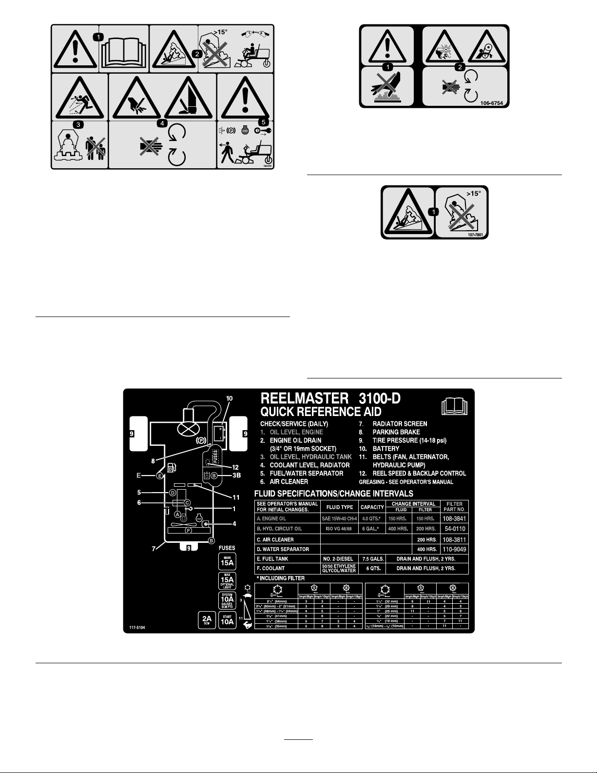
104-5181
CEonly
1.Warning—readtheOperator’sManual.
2.Tippinghazard—donotdriveonslopesgreaterthan15
degreesand,iftherollbarisinstalled,weartheseatbelt.
3.Thrownobjecthazard—keepbystandersasafedistance
fromthemachine.
4.Cuttinghazardofhandorfoot—stayawayfrommoving
parts.
5.Warning—locktheparkingbrake,stoptheengine,and
removetheignitionkeybeforeleavingthemachine.
106-6754
1.Warning—donottouchthehotsurface.
2.Cutting/dismembermenthazard,fanandentanglement
hazard,belt—stayawayfrommovingparts.
107-7801
(CEonly)
*Thissafetydecalincludesaslopewarningrequiredonthemachinefor
compliancetotheEuropeanLawnMowerSafetyStandardEN836:1997.The
conservativemaximumslopeanglesindicatedforoperationofthismachineare
prescribedbyandrequiredbythisstandard.
1.Tippinghazard—donotdriveonslopesgreaterthan15
degrees.
117-5104
9

104-5192
Model03207only
1.Engagethepowertakeoff
(PTO).
2.Disengagethepowertake
off(PTO).
3.Lowerthecuttingunits.7.Moverearwardtolockthe
4.Movethecuttingunitsto
theright.
5.Raisethecuttingunits.9.Engine—run
6.Movethecuttingunitsto
theleft.
liftlever .
8.Engine—stop
13.Slow
10.Engine—start
11.Fast
12.Continuousvariablesetting
10

104-5193
Model03206only
1.Engagethepowertakeoff
(PTO).
2.Disengagethepowertake
off(PTO).
3.Lowerthecuttingunits.7.Moverearwardtolockthe
4.Movethecuttingunitsto
theright.
5.Raisethecuttingunits.9.Engine—run
6.Movethecuttingunitsto
theleft.
liftlever .
8.Engine—stop
BatterySymbols
Someorallofthesesymbolsareonyourbattery
1.Explosionhazard
2.Nore,opename,or
smoking.
3.Causticliquid/chemical
burnhazard
4.Weareyeprotection9.Flusheyesimmediately
5.ReadtheOperator's
Manual.
6.Keepbystandersasafe
distancefromthebattery.
7.Weareyeprotection;
explosivegasescan
causeblindnessandother
injuries
8.Batteryacidcancause
blindnessorsevereburns.
withwaterandgetmedical
helpfast.
10.Containslead;donot
discard.
13.Slow
10.Engine—start
11.Fast
12.Continuousvariablesetting
11

Setup
LooseParts
Usethechartbelowtoverifythatallpartshavebeenshipped.
ProcedureDescription
1
2
3
4
5
6
7
8
9
Frontwheelassemblies2
Rearwheelassembly1
Steeringwheel
Steeringwheelcap
Largewasher1
Jamnut1
Screw
Electrolyte
Inclinometer1
Lockbracket1
Rivet2
Washer1
Screw,1/4x2inches
Locknut,1/4inch
Exhaustguard1
Self-tappingscrew
Rollbarassembly1
Flangeheadbolts4
Locknuts4
Hoseclamp1
Liftarms
Pivotrod2
Bolt(5/16x7/8inch)
Nopartsrequired
Qty.
A/R
Use
Installthewheels.
1
1
Installthesteeringwheel.
1
Activate,charge,andconnectthe
battery.
Checktheangleindicator.
InstalltheHoodLatch(CE).
1
1
4
2
2
–
InstalltheExhaustGuard(CE).
Installtherollbar.
Installthefrontliftarms.(Partssupplied
intheLiftArmKit.)
Installthecarrierframestothecutting
units.
10
11
12
Nopartsrequired
Nopartsrequired
Nopartsrequired
12
–
–
–
Mountthecuttingunits.
Mountthecuttingunitdrivemotors.
Adjusttheliftarms.

MediaandAdditionalParts
Description
Decal,CE
Ignitionkey2
Operator'sManual
EngineOperator'sManual
PartsCatalog
OperatorTrainingMaterial
Pre-deliverychecklist1
Certicateofcompliance
Note:Determinetheleftandrightsidesofthemachine
fromthenormaloperatingposition.
1
InstallingtheWheels
Partsneededforthisprocedure:
2Frontwheelassemblies
1Rearwheelassembly
Qty.
6
1
1
1Usetolookupandorderparts.
1
1
AfxtothemachineovercorrespondingEnglishdecals
forEuropeancompliance.
Starttheengine.
Readbeforeoperatingthemachine.
Viewbeforeoperatingthemachine.
Checktoensurethatthemachinehasbeenproperlyset
up.
EnsureCEcompliance.
2
InstallingtheSteeringWheel
Partsneededforthisprocedure:
1
Steeringwheel
1
Steeringwheelcap
1Largewasher
1Jamnut
1
Screw
Use
Procedure
1.Mountawheelassemblyontoeachwheelhub(valve
stemoutward).
Important:Thereartirehasanarrowerrimthan
thefronttires.
2.Installlugnutsandtorqueto61to88N-m(45to65
ft-lb).
Procedure
1.Slidethesteeringwheelontothesteeringshaft(Figure
3).
Figure3
1.Steeringwheel
2.Washer
2.Slidethewasherontothesteeringshaft(Figure3).
3.Jamnut
4.Cap
13

3.Securethesteeringwheeltotheshaftwithajamnut
andtightenitto27to35N-m(20to26ft-lb)(Figure3).
4.Installthecaptothesteeringwheelandsecureitwitha
screw(Figure3).
3
Activating,Charging,and ConnectingtheBattery
Partsneededforthisprocedure:
A/R
Procedure
Note:Ifthebatteryisnotlledwithelectrolyteoractivated,
bulkelectrolytewith1.260specicgravitymustbepurchased
fromalocalbatterysupplyoutletandaddedtothebattery.
Batteryelectrolytecontainssulfuricacidwhichisa
deadlypoisonandcausessevereburns.
•Donotdrinkelectrolyteandavoidcontactwith
•Fillthebatterywherecleanwaterisalways
1.Purchasebulkelectrolytewith1.260specicgravity
2.Openthehood.
3.Removethebatterycover(
Electrolyte
WARNING
CALIFORNIA
Proposition65Warning
Batteryposts,terminals,andrelated
accessoriescontainleadandleadcompounds,
chemicalsknowntotheStateofCalifornia
tocausecancerandreproductiveharm.
W ash hands after handling .
DANGER
skin,eyes,orclothing.Wearsafetyglassesto
shieldyoureyesandrubberglovestoprotect
yourhands.
availableforushingtheskin.
fromalocalbatterysupplyoutlet.
Figure4).
Figure4
1.Batterycover
4.Removethellercapsfromthebatteryandslowlyll
eachcelluntilelectrolyteisjustabovetheplates.
5.Installthellercapsandconnecta3to4ampbattery
chargertothebatteryposts.Chargethebatteryata
rateof3to4ampsfor4to8hours.
WARNING
Chargingthebatteryproducesgassesthatcan
explode.
•Keepsparksandamesawayfrombattery.
•Neversmokenearthebattery.
6.Whenthebatteryischarged,disconnectthecharger
fromtheelectricaloutletandbatteryposts.
7.Removethellercaps.Slowlyaddelectrolytetoeach
celluntilthelevelisuptothellring.Installtheller
caps.
Important:Donotoverllthebattery.Electrolyte
willoverowontootherpartsofthemachineand
severecorrosionanddeteriorationwillresult.
8.Installthepositivecable(red)tothepositive(+)
terminalandthenegativecable(black)tothenegative
(–)terminalofthebatteryandsecurethemwithbolts
andnuts(Figure5).Makesurethatthepositive(+)
terminalisallofthewayontothepostandthecable
ispositionedsnugtothebattery.Thecablemustnot
contactthebatterycover.
WARNING
Incorrectbatterycableroutingcoulddamage
thetractorandcablescausingsparks.Sparks
cancausethebatterygassestoexplode,
resultinginpersonalinjury.
•Alwaysdisconnectthenegative(black)
batterycablebeforedisconnectingthe
positive(red)cable.
•Alwaysconnectthepositive(red)battery
cablebeforeconnectingthenegative
(black)cable.
14

Figure5
1.Positive(+)batterycable2.Negative(–)batterycable
Important:Ifthebatteryiseverremoved,make
surethatthebatteryclampboltsareinstalledwith
theboltheadspositionedonthebottomsideand
thenutsonthetopside.Iftheclampboltsare
reversed,theymayinterferewiththehydraulic
tubeswhenshiftingthecuttingunits.
9.CoatbothbatteryconnectionswithGrafo112X(skin
over)grease,T oroPartNo.505-47,petroleumjelly,or
lightgreasetopreventcorrosion.
10.Slidetherubberbootoverthepositiveterminalto
preventapossibleshortfromoccurring.
11.Installthebatterycover.
4
CheckingtheAngleIndicator
Partsneededforthisprocedure:
1Inclinometer
Figure6
1.Angleindicator
3.Iftheinclinometerdoesnotreadzerodegrees,move
themachinetoalocationwhereazerodegreereading
isobtained.Theangleindicator,mountedonthe
machine,shouldnowreadzerodegreesaswell.
4.Iftheangleindicatordoesnotreadzerodegrees,
loosenthetwoscrewsandnutssecuringtheangle
indicatortothemountingbracket,adjusttheindicator
toobtainazerodegreereading,andtightenthebolts.
5
InstallingtheHoodLatch(CE Only)
Partsneededforthisprocedure:
1Lockbracket
2Rivet
1Washer
1
Screw,1/4x2inches
1
Locknut,1/4inch
Procedure
DANGER
Toreduceriskofinjuryordeathduetorollover,do
notoperatethemachineonsidehillssteeperthan
25º.
1.Parkthemachineonaat,levelsurface.
2.Verifythatthemachineislevelbyplacingahandheld
inclinometer(suppliedwiththemachine)ontheframe
crossrail,bythefueltank(Figure6).Theinclinometer
shouldreadzerodegreeswhenviewedfromthe
operator’sposition.
Procedure
1.Unhookthehoodlatchfromthehoodlatchbracket.
2.Removethe(2)rivetssecuringthehoodlatchbracket
tothehood(
fromthehood.
15
Figure7).Removethehoodlatchbracket

G012628
1
2
G012629
1
2
G012630
1
Figure9
G012631
1
2
3
Figure7
1.Hoodlatchbracket2.Rivets
3.Whilealigningthemountingholes,positiontheCE
lockbracketandthehoodlatchbracketontothehood.
Thelockbracketmustbeagainstthehood(Figure8).
Donotremoveboltandnutassemblyfromthelock
bracketarm.
Figure8
1.Hoodlatch
7.Screwtheboltintotheotherarmofhoodlockbracket
tolockthelatchinposition(Figure10).Tightenbolt
securelybutdonottightennut.
Figure10
1.Bolt
2.Nut
3.Armofhoodlockbracket
1.CElockbracket
2.Boltandnutassembly
6
4.Alignthewasherswiththeholesontheinsideofthe
hood.
5.Rivetthebracketsandthewasherstothehood(Figure
8).
6.Hookthelatchontothehoodlatchbracket(Figure9).
InstallingtheExhaustGuard (CEOnly)
Partsneededforthisprocedure:
1Exhaustguard
4
Self-tappingscrew
Procedure
1.Positiontheexhaustguardaroundthemuferwhile
aligningthemountingholeswiththeholesintheframe
(
Figure11).
16

Figure12
Figure11
1.Exhaustguard
2.Securetheexhaustguardtotheframewith4
self-tappingscrews(Figure11).
7
InstallingtheRollBar
Partsneededforthisprocedure:
1Rollbarassembly
4Flangeheadbolts
4Locknuts
1Hoseclamp
Procedure
1.ROPS
2.Mountingbracket5.Hoseclamp
3.Venttube
2.Secureeachsideoftherollbartothemounting
bracketswith2angeheadboltsandlocknuts(Figure
12).T orquethefastenersto81N-m(60ft-lb).
3.Securethefuellineventhosetotheventtubeonthe
rollbarwiththehoseclamp.
4.Fuellineventtubehose
CAUTION
Youmustconnectthefuellineventhosetothe
venttubepriortostartingtheengineorfuel
willowfromthehose.
8
InstallingtheFrontLiftArms
Partsneededforthisprocedure:
2
Liftarms
2Pivotrod
2
Bolt(5/16x7/8inch)
Important:Neverweldormodifyarolloverprotection
system(ROPS).ReplaceadamagedROPS,donotrepair
orrevise.AnyalterationofaROPSmustbeapproved
bythemanufacturer.
1.Lowertherollbarontothetractionunitmounting
brackets,aligningthemountingholes.Ensurethat
theventtubeontherollbarisontheleftsideofthe
machine(
Figure12).
Procedure
1.Removethe2boltsthatsecuretheliftarmpivotshaft
linktotheliftarmpivotshafts,andremoveandretain
thepivotshaftlinkandbolts(
17
Figure13).

Figure13
Figure15
1.Liftarm,pivotshaftlink2.Liftarmpivotshaft
2.Insertapivotrodintoeachliftarmandalignthe
mountingholes(Figure14).
Figure14
1.Liftarm
3.Securethepivotrodstotheliftarmswith2bolts(5/16
x7/8inch).
4.Inserttheliftarmsontotheliftarmpivotshafts(
15
),andsecureeachwithaliftarmpivotshaftlinkand
boltspreviouslyremoved.
2.Pivotrod
1.Liftarm,right4.Liftcylinder
2.Retainingring
3.Liftarm,left
5.Removetherearretainingringssecuringthemounting
pinstoeachendoftheliftcylinder.
6.Securetherightendoftheliftcylindertotherightlift
armwithapinand2spacers(Figure15).Secureitwith
aretainingring.
7.Securetheleftendoftheliftcylindertotheleftliftarm
withapin.Secureitwitharetainingring.
5.Spacers(2)
6.Mountingpin
9
InstallingtheCarrierFrames totheCuttingUnits
Figure
NoPartsRequired
Note:Torquetheboltsto95N-m(70ft-lb).
Procedure
1.Removethecuttingunitsfromthecartons.Adjust
themasdescribedintheCuttingUnitOperator’sManual.
2.Positionafrontcarrierframe(Figure16)ontoeach
frontcuttingunit.
18
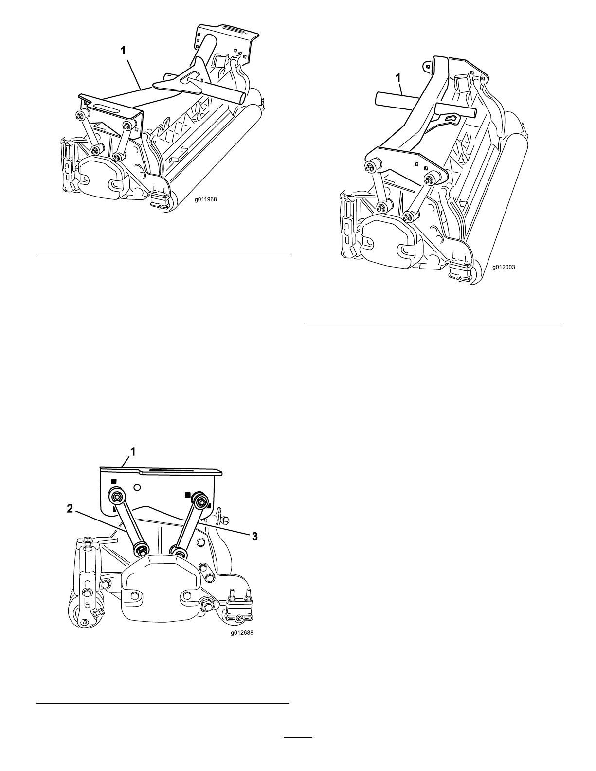
Figure16
1.Frontcarrierframe
3.Securethemountinglinkstothefrontcarrierframes
asfollows:
•Securethefrontmountinglinkstothemiddle
carrierframeholeswithabolt(3/8x2-1/4inch),
2atwashers,andalocknut,asshowninFigure
17.Positionawasheroneachsideofthelinkwhen
mounting.Torquethefastenersto42N-m(31
ft-lb).
•Securetherearmountinglinkstothemiddlecarrier
frameholeswithabolt(3/8x2-1/4inch),2at
washers,andalocknut,asshowninFigure17.
Positionawasheroneachsideofthelinkwhen
mounting.Torquethefastenersto42N-m(31
ft-lb).
4.Positiontherearcarrierframe(Figure18)ontotherear
cuttingunit.
Figure18
1.Rearcarrierframe
5.Securethemountinglinkstotherearcarrierframeas
follows:
•Securethefrontmountinglinkstothecarrierframe
holeswithabolt(3/8x2-1/4inch),2atwashers,
andalocknut,asshownin
Figure19.Positiona
washeroneachsideofthelinkwhenmounting.
Torquethefastenersto31ft-lb(42N-m).
•Securetherearmountinglinkstotherearcarrier
frameholeswithabolt(3/8x2-1/4inch),2at
washers,andalocknut,asshowninFigure19.
Positionawasheroneachsideofthelinkwhen
mounting.Torquethefastenersto31ft-lb(42
N-m).
1.Frontcarrierframe
2.Frontmountinglink
3.Rearmountinglink
Figure17
19

Figure19
unithosesareroutedasshowin(Figure21).
Raisethecuttingunitsandshiftthemtotheleft
(Model03170).Therearcuttingunithosesmust
notcontacttractioncablebracket.Repositionthe
ttingsand/orhoses,ifnecessary.
1.Rearcarrierframe
2.Frontmountinglink
3.Rearmountinglink
10
MountingtheCuttingUnits
NoPartsRequired
Procedure
1.Slideathrustwasherontoeachfrontliftarmpivotrod.
2.Slidethecuttingunitcarrierframeontothepivotrod
andsecureitwithalynchpin(
Note:Onrearcuttingunit,positionthethrustwasher
betweentherearofthecarrierframeandthelynchpin.
Figure20).
Figure21
4.Routeatipperchainupthroughtheslotontheendof
eachcarrierframe.Securethetipperchaintothetop
ofthecarrierframewithabolt,awasher,andalocknut
(Figure22).
Figure22
1.Tipperchain
Figure20
1.Thrustwasher3.Lynchpin
2.Carrierframe
3.Greasealltheliftarmandcarrierframepivotpoints.
Important:Ensurethatthehosesarefreeof
twistsorsharpbendsandthattherearcutting
11
MountingtheCuttingUnit DriveMotors
NoPartsRequired
Procedure
1.Positionthecuttingunitsinfrontoftheliftarmpivot
rods.
2.Removetheweightando-ring(Figure23)fromthe
insideendoftherighthandcuttingunit.
20

Figure23
12
AdjustingtheLiftArms
NoPartsRequired
Procedure
1.Starttheengine,raisetheliftarms,andchecktoensure
thattheclearancebetweeneachliftarmandtheoor
platebracketis5to8mm(0.18to0.32inches)(Figure
25).
1.O-ring
2.Weight
3.Removetheplugfromthebearinghousingonthe
outsideendoftherighthandcuttingunitandinstall
theweightsandgasket.
4.Removetheshippingplugfromthebearinghousings
ontheremainingcuttingunits.
5.InserttheO-ring(suppliedwiththecuttingunit)on
theangeofthedrivemotor(Figure24).
3.Mountingbolts
Figure25
Cuttingunitsremovedforclarity
1.Liftarm3.Clearance
2.Floorplatebracket
Note:Iftheclearanceisnotinthisrange,adjustthe
cylinderasfollows:
A.Backoffthestopboltsandadjustthecylinderto
attaintheclearance(Figure26).
Figure24
1.O-ring
6.Mountthemotortothedriveendofthecuttingunit,
andsecureitwithtwocapscrewsprovidedwithcutting
unit(Figure24).
2.Reelmotor
Figure26
1.Stopbolt3.Clearance
2.Liftarm
B.Backoffthejamnutonthecylinder(Figure27).
21
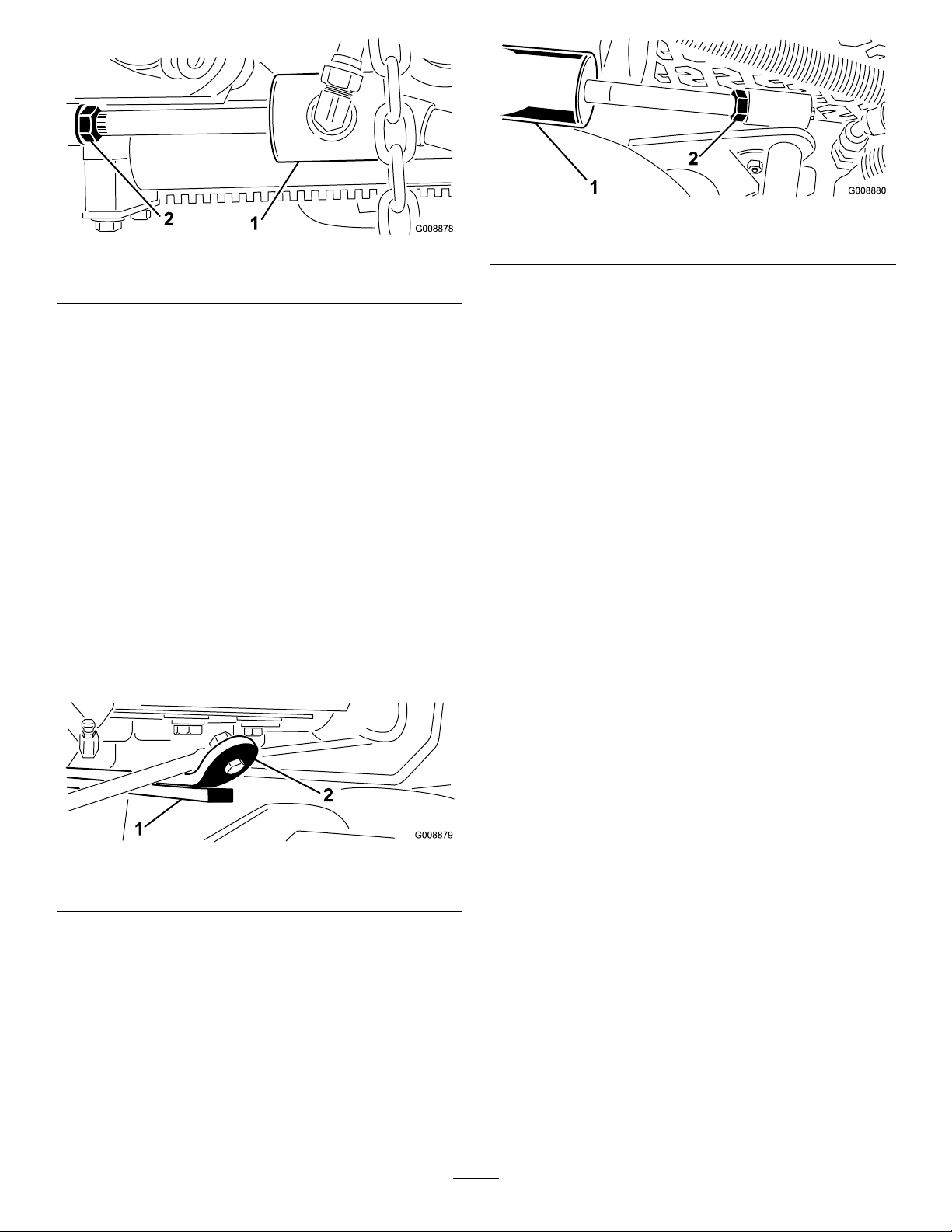
Figure29
Figure27
1.Frontcylinder2.Jamnut
C.Removethepinfromtherodendandrotatethe
clevis.
D.Installthepinandchecktheclearance.
E.RepeatstepsAthroughDifnecessary.
F.Tightentheclevisjamnut.
Note:Iftherearliftarmclunksduringtransport,
reducetheclearance.
2.Checktoensurethattheclearancebetweeneachlift
armandstopboltis0.13to1.02mm(0.005to0.040
inches)(Figure26).
Note:Iftheclearanceisnotinthisrange,adjustthe
stopboltstoattainclearance.
3.Starttheengine,raisetheliftarms,andchecktoensure
thattheclearancebetweenthewearstraponthetopof
therearcuttingunitwearbarandthebumperstrapis
0.51to2.54mm(0.02to0.10inches)(Figure28).
1.Rearcylinder2.Adjustingnut
B.Graspthecylinderrodclosetothenutwitha
pliersandragandrotatetherod.
C.Raisethecuttingunitsandchecktheclearance.
D.RepeatstepsAthroughCifnecessary.
E.Tightentheclevisjamnut.
Important:Lackofclearanceatthefrontstopsorthe
rearwearbarcoulddamagetheliftarms.
Figure28
1.Wearbar2.Bumperstrap
Iftheclearanceisnotinthisrange,adjusttherear
cylinderasfollows:
A.Lowerthecuttingunitsandbackoffthejamnut
onthecylinder(Figure29).
22
ProductOverview
Controls
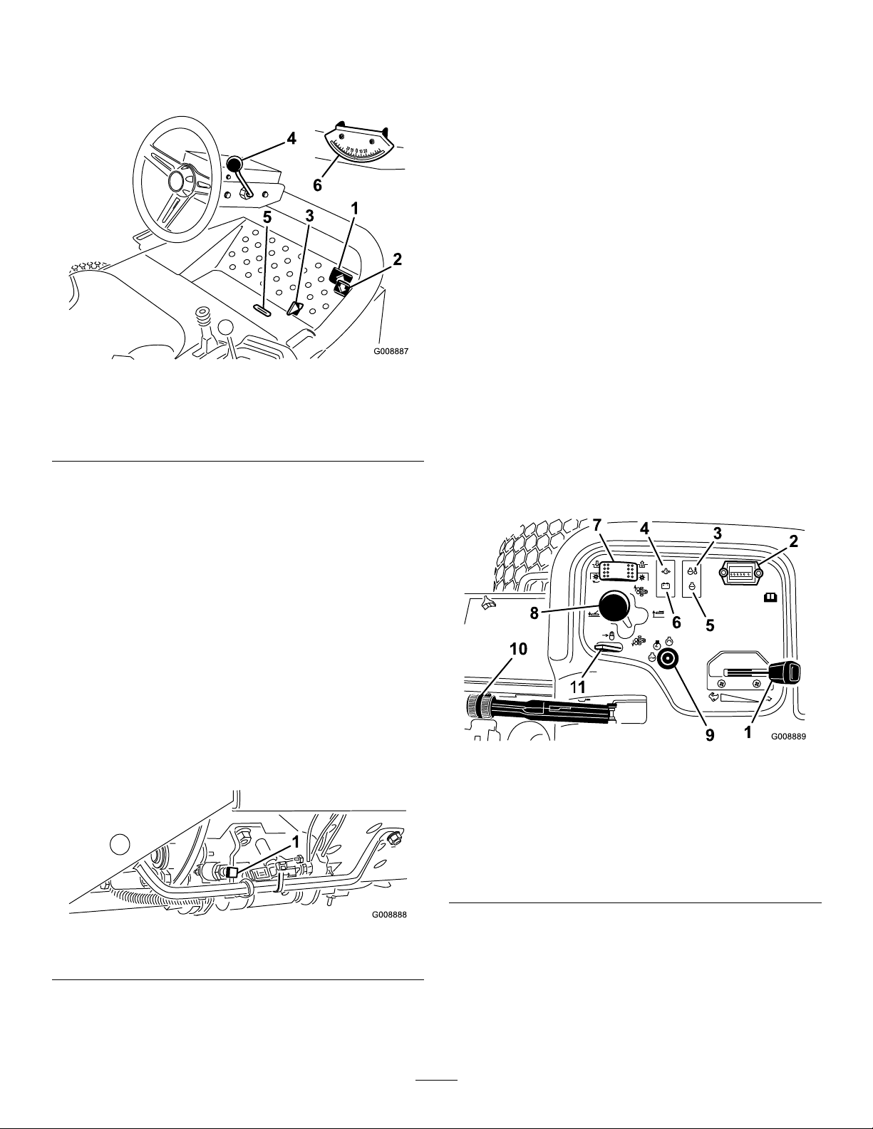
TiltSteeringLever
Pullthetiltsteeringlever(Figure30)backtoadjustthe
steeringwheeltothedesiredposition,thenpushthelever
forwardtotighten.
IndicatorSlot
Theslotintheoperatorplatform(Figure30)indicateswhen
thecuttingunitsareinthecenterposition.
AngleIndicator
Theangleindicator(Figure30)indicatesthesidehillangleof
themachineindegrees.
IgnitionSwitch
Figure30
1.Forwardtractionpedal4.Tiltsteeringlever
2.Reversetractionpedal5.Indicatorslot
3.Mow/transportslide
6.Angleindicator
TractionPedals
Pressthetractionforwardpedal(Figure30)tomoveforward.
Presstractionreversepedal(
toassistinstoppingwhenmovingforward.Also,allowthe
pedaltomoveormoveittotheneutralpositiontostopthe
machine.
Figure30)tomovebackwardor
Mow/TransportSlide
Usingyourheel,movethemow/transportslide(Figure30)
tothelefttotransportandtotherighttomow.Thecutting
unitswillonlyoperateinthemowposition.
Important:Themowspeedissetatthefactoryto9.7
km/h(6mph).Itcanbeincreasedordecreasedby
adjustingthespeedstopscrew(
Figure31).
Theignitionswitch(Figure32),whichisusedtostart,stop,
andpreheattheengine,hasthreepositions:Off,On/Preheat,
andStart.RotatethekeytotheOn/Preheatpositionuntilthe
glowplugindicatorlightgoesout(approximately7seconds);
thenrotatethekeytotheStartpositiontoengagethestarter
motor.Releasethekeywhentheenginestarts.Thekeywill
moveautomaticallytotheOn/Runposition.T oshutthe
engineoff,rotatethekeytotheOffpositionandremovethe
keyfromtheswitchtopreventaccidentalstarting.
Figure32
1.Throttle
2.Hourmeter
3.Temperaturelight9.Ignitionswitch
4.Oilpressurelight
5.Glowplugindicatorlight1 1.Liftleverlock
6.Alternatorlight
7.Cuttingunitdriveswitch
8.Cuttingunitshiftlever
10.Parkingbrake
1.Speedstopscrew
Figure31
Throttle
Movethethrottle(Figure32)forwardtoincreasetheengine
speedandrearwardtodecreasetheenginespeed.
23
CuttingUnitDriveSwitch
ParkingBrake
Thecuttingunitdriveswitch(Figure32)hastwopositions:
EngageandDisengage.Therockerswitchoperatesasolenoid
valveonthevalvebanktodrivethecuttingunits.
HourMeter
Thehourmeter(Figure32)indicatesthetotalhoursof
machineoperation.Thehourmeterstartstofunction
wheneverthekeyswitchisOn.
CuttingUnitShiftLever
Tolowerthecuttingunitstotheground,movethecutting
unitshiftlever(Figure32)forward.Thecuttingunitswillnot
dropunlesstheengineisrunning,andtheywillnotoperatein
theraisedposition.Toraisethecuttingunits,pulltheshift
leverrearwardtotheRaiseposition.
Movethelevertotherightorlefttomovethecuttingunits
inthesamedirection.Thisshouldonlybedonewhenthe
cuttingunitsareraisedoriftheyareonthegroundandthe
machineismoving(Model03170only).
Note:Theleverdoesnothavetobeheldintheforward
positionwhilethecuttingunitsarelowered.
Whenevertheengineisshutoff,engagetheparkingbrake
(Figure32)topreventaccidentalmovementofthemachine.
Toengagetheparkingbrake,pulluponthelever.Theengine
willstopifyoupressthetractionpedalwiththeparkingbrake
engaged.
LiftLeverLock
Movetheliftleverlock(Figure32)rearwardtopreventthe
cuttingunitsfromdropping.
ReelSpeedControl
Thereelspeedcontrolislocatedundertheconsolecover
(Figure33).Toobtainthedesiredcliprate(reelspeed),rotate
thereelspeedcontrolknobtotheappropriateheight-of-cut
settingandmowerspeed.RefertoSelectingtheClipRate.
DANGER
Shiftingthecuttingunitsdownhilldecreases
machinestability.Thiscouldcausearollover,
whichmayresultinpersonalinjuryordeath.
Shiftthecuttingunitsuphillwhileonasidehill.
EngineCoolantTemperatureWarning
Light
Thetemperaturewarninglight(Figure32)glowsiftheengine
coolanttemperatureishigh.Ifthetractionunitisnotstopped
andthecoolanttemperaturerisesanother10°F,theengine
willkill.
OilPressureWarningLight
Theoilpressurewarninglight(Figure32)glowsiftheengine
oilpressuredropsbelowasafelevel.
AlternatorLight
Thealternatorlight(Figure32)shouldbeoffwhentheengine
isrunning.Ifitison,thechargingsystemshouldbechecked
andrepairedasnecessary.
Figure33
1.Reelspeedcontrol2.Backlapcontrol
BacklapControl
Thebacklapcontrolislocatedundertheconsolecover
(Figure33).RotatetheknobtoRforbacklappingandtoF
formowing.Donotchangetheknobpositionwhilethe
reelsarerotating.
FuelGauge
Thefuelgauge(Figure34)registerstheamountoffuelin
thetank.
GlowPlugIndicator
Theglowplugindicatorlight(Figure32)willglowwhenthe
glowplugsareoperating.
24
Operation
Note:Determinetheleftandrightsidesofthemachine
fromthenormaloperatingposition.
CheckingtheEngineOilLevel
ServiceInterval:Beforeeachuseordaily
Theengineisshippedwithoilinthecrankcase;however,the
oillevelmustbecheckedbeforeandaftertheengineisrst
started.
Crankcasecapacityisapproximately2.8liters(4quarts)with
thelter.
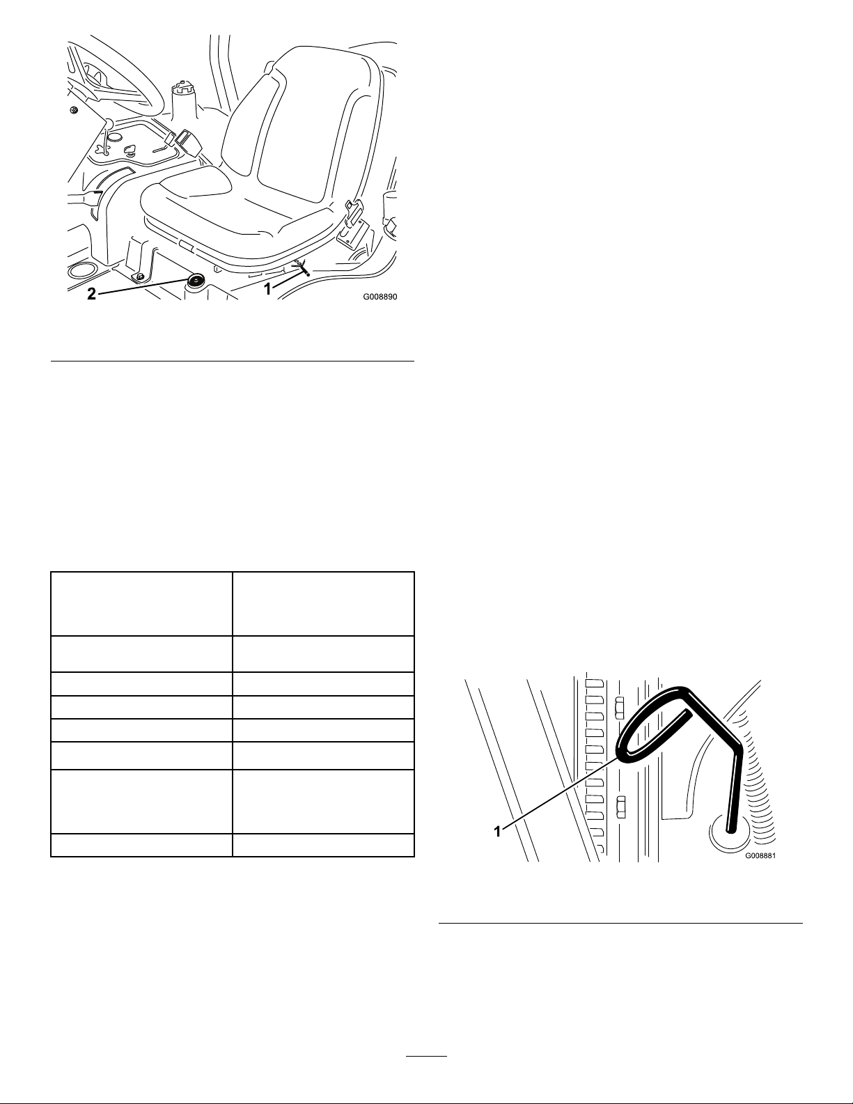
Figure34
1.Foreandaftlever
2.Fuelgauge
ForeandAftSeatAdjustments
Movethelever(Figure34)onthesideoftheseatoutward,
slidetheseattothedesiredposition,andreleasethelever
tolocktheseatintoposition.
Specications
Note:Specicationsanddesignaresubjecttochange
withoutnotice.
TransportWidth
Widthofcut183cm(72inches)or216cm
Length
Height
Netweight*844kg(1860lbs)
Fueltankcapacity
203cm(80inches)in183
cm(72inches)widthofcut
234cm(92inches)in216cm
(85inches)widthofcut
(85inches)widthofcut
248cm(93inch)
180cm(71inches)withROPS
28liters(7.5gallons).
Usehigh-qualityengineoilthatmeetsthefollowing
specications:
•APIClassicationLevelRequired:CH-4,CI-4orhigher.
•Preferredoil:SAE15W-40(above0ºF(-17ºC))
•Alternateoil:SAE10W-30or5W-30(alltemperatures)
Note:ToroPremiumEngineoilisavailablefroma
distributorineither15W-40or10W-30viscosity.Seethe
partscatalogforpartnumbers.
Note:Thebesttimetochecktheengineoiliswhenthe
engineiscoolbeforeithasbeenstartedfortheday.Ifit
hasalreadybeenrun,allowtheoiltodrainbackdownto
thesumpforatleast10minutesbeforechecking.Iftheoil
levelisatorbelowthe“add”markonthedipstick,addoilto
bringtheoilleveltothe“full”mark.Donotoverll.Ifthe
oillevelisbetweenthe“full”and“add”marks,youdonot
needtoaddoil.
1.Positionthemachineonalevelsurface.
2.Removethedipstick(Figure35)andwipeitwitha
cleanrag.
GroundspeedMow:0-10km/h(0-6mph);
Transport:0-14km/h(0-9
mph).Reverse:0-6km/h(0-4
mph)
*Withcuttingunitsanduids
Attachments/Accessories
AselectionofToroapprovedattachmentsandaccessoriesis
availableforusewiththemachinetoenhanceandexpand
itscapabilities.ContactyourAuthorizedServiceDealeror
Distributororgotowww .Toro.comforalistofallapproved
attachmentsandaccessories.
Figure35
1.Dipstick
3.Pushthedipstickdownintothedipsticktubeand
ensurethatitisseatedfully,thenpullthedipstickout
andchecktheoillevel.
4.Iftheoillevelislow ,removetheoilllcap(Figure36)
andgraduallyaddsmallquantitiesofoil,checkingthe
25

levelfrequently,untilthelevelreachestheFullmark
onthedipstick.
Figure36
1.Oilllcap
5.Installtheoilllcapandclosethehood.
Important:Besuretokeeptheengineoillevel
betweentheupperandlowerlimitsontheoil
gauge.Enginefailuremayoccurasaresultofover
llingorunderllingtheengineoil.
FillingtheFuelTank
DANGER
Undercertainconditions,dieselfuelandfuel
vaporsarehighlyammableandexplosive.Are
orexplosionfromfuelcanburnyouandothersand
cancausepropertydamage.
fuelatlowertemperaturesprovidesalowerashpointand
coldowcharacteristicswhichwilleasestartingandreduce
pluggingofthefuellter.
Useofsummergradefuelabove-7°C(20°F)willcontribute
towardlongerfuelpumplifeandincreasedpowercompared
towintergradefuel.
BiodieselReady
Thismachinecanalsouseabiodieselblendedfuelofup
toB20(20%biodiesel,80%petrodiesel).Thepetrodiesel
portionshouldbeloworultralowsulfur.Observethe
followingprecautions:
•Thebiodieselportionofthefuelmustmeetspecication
ASTMD6751orEN14214.
•TheblendedfuelcompositionshouldmeetASTMD975
orEN590.
•Paintedsurfacesmaybedamagedbybiodieselblends.
•UseB5(biodieselcontentof5%)orlesserblendsincold
weather.
•Monitorseals,hoses,gasketsincontactwithfuelasthey
maybedegradedovertime.
•Fuellterpluggingmaybeexpectedforatimeafter
convertingtobiodieselblends.
•Contactadistributorformoreinformationonbiodiesel
blendedfuel.
1.Cleantheareaaroundthefueltankcap(
Figure37).
•Useafunnelandllthefueltankoutdoors,in
anopenarea,whentheengineisoffandiscold.
Wipeupanyfuelthatspills.
•Donotllthefueltankcompletelyfull.Add
fueltothefueltankuntilthelevelis6to13mm
(1/4to1/2inch)belowthebottomoftheller
neck.Thisemptyspaceinthetankallowsthe
fueltoexpand.
•Neversmokewhenhandlingfuel,andstayaway
fromanopenameorwherefuelfumesmaybe
ignitedbyaspark.
•Storefuelinaclean,safety-approvedcontainer
andkeepthecapinplace.
Useonlyclean,freshdieselfuelorbiodieselfuelswithlow
(<500ppm)orultralow(<15ppm)sulfurcontent.The
minimumcetaneratingshouldbe40.Purchasefuelin
quantitiesthatcanbeusedwithin180daystoensurefuel
freshness.
Thefueltankcapacityisapproximately28liters(7.5gallons).
Usesummergradedieselfuel(No.2-D)attemperatures
above-7°C(20°F)andwintergrade(No.1-DorNo.
1-D/2-Dblend)belowthattemperature.Usingwintergrade
Figure37
1.Fueltankcap
2.Removethefueltankcap.
3.Fillthetanktothebottomofthellerneck.Donot
overll.
4.Installthecap.
5.Wipeupanyfuelthatmayhavespilled.
CheckingtheCoolingSystem
ServiceInterval:Beforeeachuseordaily
Cleandebrisoffoftheradiatorandtheoilcoolerdaily(Figure
38).Cleantheradiatorhourlyifconditionsareextremely
dustyanddirty;refertoCleaningtheEngineCoolingSystem.
26

Figure38
1.Accesspanel
2.Radiator
3.Oilcooler
Thecoolingsystemislledwitha50/50solutionofwater
andpermanentethyleneglycolanti-freeze.Checkthecoolant
levelatthebeginningofeachdaybeforestartingtheengine.
Thecapacityofthecoolingsystemisapproximately5.7liters
(6quarts).
2.Ifthecoolantlevelislow,removetheexpansiontank
capandreplenishthesystem.Donotoverll.
3.Installtheexpansiontankcap.
CheckingtheHydraulic System
ServiceInterval:Beforeeachuseordaily—Checkthe
hydraulicuidlevel.
Thehydraulicuidtankislledatthefactorywith
approximately13.2liters(3.5U.S.gallons)ofhigh-quality
hydraulicuid.Checkthelevelofthehydraulicuid
beforetheengineisrststartedanddailythereafter.
TherecommendedreplacementuidisT oroPremium
AllSeasonHydraulicFluid(Availablein5-gallonpailsor
55-gallondrums.SeepartscatalogorTorodistributorfor
partnumbers.)
Alternateuids:IftheT orouidisnotavailable,other
uidsmaybeusedprovidedtheymeetallthefollowing
materialpropertiesandindustryspecications.Torodoesnot
recommendusingsyntheticuid.Consultwithalubricant
distributortoidentifyasatisfactoryproduct.
CAUTION
Iftheenginehasbeenrunning,thepressurized,hot
coolantcanescapeandcauseburns.
•Donotopentheradiatorcapwhentheengine
isrunning.
•Usearagwhenopeningtheradiatorcap,and
openthecapslowlytoallowsteamtoescape.
1.Checkthecoolantlevelintheexpansiontank(Figure
).
39
Figure39
1.Expansiontank
Note:Withacoldengine,thecoolantlevelshouldbe
approximatelymidwaybetweenthemarksontheside
ofthetank.
Note:Torowillnotassumeresponsibilityfordamage
causedbyimpropersubstitutions,souseonlyproducts
fromreputablemanufacturerswhowillstandbehindtheir
recommendation.
HighViscosityIndex/LowPourPointAnti-wearHydraulic
Fluid,ISOVG46
MaterialProperties:
Viscosity,ASTMD445cSt@40°C44to48
ViscosityIndexASTM
D2270
PourPoint,ASTMD97-34°Fto-49°F
IndustrySpecications:
VickersI-286-S(QualityLevel),VickersM-2950-S
(QualityLevel),DenisonHF-0
cSt@100°C7.9to8.5
140to160
Important:TheISOVG46Multigradeuidhasbeen
foundtoofferoptimalperformanceinawiderangeof
temperatureconditions.Foroperationinconsistently
highambienttemperatures,65°F(18°C)to120°F
(49°C),ISOVG68hydraulicuidmayofferimproved
performance.
PremiumBiodegradableHydraulicFluid-MobilEAL
EnviroSyn46H
Important:MobilEALEnviroSyn46Histheonly
syntheticbiodegradableuidapprovedbyT oro.This
uidiscompatiblewiththeelastomersusedinToro
hydraulicsystemsandissuitableforawide-range
oftemperatureconditions.Thisuidiscompatible
withconventionalmineraloils,butformaximum
biodegradabilityandperformancethehydraulicsystem
shouldbethoroughlyushedofconventionaluid.The
oilisavailablein19liters(5gallon)containersor55
gallondrumsfromyourMobilDistributor.
27

Important:Manyhydraulicuidsarealmostcolorless,
makingitdifculttospotleaks.Areddyeadditive
forthehydraulicsystemoilisavailablein20ml(2/3
oz.)bottles.Onebottleissufcientfor15-22liters(4-6
gallons)ofhydraulicoil.Orderpartno.44-2500from
yourauthorizedT orodistributor.
1.Positionthemachineonalevelsurface,lowerthe
cuttingunits,andstoptheengine.
2.Cleantheareaaroundthellerneckandcapofthe
hydraulicuidtank(Figure40)andremovethecap.
CheckingtheReel-to-Bedknife Contact
ServiceInterval:Beforeeachuseordaily
Checkthereel-to-bedknifecontactevenifthequalityof
cuthadbeenacceptablepreviously.Theremustbelight
contactacrossthefulllengthofthereelandbedknife;refer
toAdjustingReeltoBedknifeintheCuttingUnitOperator’ s
Manual.
TorquingtheWheelNuts
ServiceInterval:Afterthersthour
Aftertherst10hours
Every200hours
Torquethewheelnutsto61to88N-m(45to65ft-lb).
WARNING
Failuretomaintainpropertorqueofthewheelnuts
couldresultinpersonalinjury.
Figure40
1.Hydraulicuidtankcap
3.Removethedipstickfromthellerneckandwipeit
withacleanrag.Insertthedipstickintothellerneck;
thenremoveitandchecktheuidlevel.Theuidlevel
shouldbewithin6mm(1/4inch)ofthemarkonthe
dipstick.
4.Ifthelevelislow ,addtheappropriateuidtoraisethe
leveltothefullmark.
5.Installthedipstickandcapontothellerneck.
CheckingtheTirePressure
ServiceInterval:Beforeeachuseordaily
Thetiresareover-inatedforshipping.Therefore,release
someoftheairtoreducethepressure.Theproperair
pressureinthetiresis97to124kPa(14to18psi).
Note:Maintaintherecommendedpressureinalltiresto
ensureagoodqualityofcutandpropermachineperformance.
StartingandStoppingthe Engine
Youmayneedtobleedthefuelsystemifanyofthe
followingsituationshaveoccurred(refertoBleeding
theFuelSystem):
•Itistheinitialstartupofanewengine.
•Theenginehasceasedrunningduetolackoffuel.
•Maintenancehasbeenperformeduponthefuel
systemcomponents;e.g.,lterreplaced,etc.
StartingtheEngine
1.Ensurethattheparkingbrakeissetandthereeldrive
switchisintheDisengageposition.
2.Removeyourfootfromthetractionpedalandensure
thatthepedalisintheneutralposition.
3.Movethethrottlelevertothe1/2throttleposition.
4.Insertthekeyintotheswitchandrotateittothe
On/Preheatpositionuntiltheglowplugindicatorlight
goesout(approximately7seconds);thenrotatethe
keytotheStartpositiontoengagethestartermotor.
Releasethekeywhentheenginestarts.
DANGER
Lowtirepressuredecreasesmachinesidehill
stability.Thiscouldcausearollover,whichmay
resultinpersonalinjuryordeath.
Donotunder-inatethetires.
Note:ThekeywillmoveautomaticallytotheOn/Run
position.
Important:Topreventoverheatingofthestarter
motor,donotengagethestarterlongerthan15
seconds.After10secondsofcontinuouscranking,
wait60secondsbeforeengagingthestartermotor
again.
5.Whentheengineisstartedforthersttimeorafteran
overhauloftheengine,operatethemachineinforward
28

andreverseforonetotwominutes.Alsooperatethe
liftleverandcuttingunitdriveswitchtoensureproper
operationofallparts.
Note:Turnthesteeringwheeltotheleftandright
tocheckthesteeringresponse,thenshuttheengine
offandcheckforoilleaks,looseparts,andanyother
noticeablemalfunctions.
CAUTION
Stoptheengineandwaitforallmovingparts
tostopbeforecheckingforoilleaks,loose
parts,andothermalfunctions.
StoppingtheEngine
MovethethrottlecontroltotheIdleposition,movethereel
driveswitchtoDisengage,androtatethestarterkeytoOff.
Note:Removethekeyfromtheswitchtopreventaccidental
starting.
BleedingtheFuelSystem
1.Parkthemachineonalevelsurface,andensurethatthe
fueltankisatleasthalffull.
2.Unlatchandraisethehood.
DANGER
Undercertainconditions,dieselfuelandfuel
vaporsarehighlyammableandexplosive.A
reorexplosionfromfuelcanburnyouand
othersandcancausepropertydamage.
•Useafunnelandllthefueltankoutdoors,
inanopenarea,whentheengineisoffand
iscold.Wipeupanyspilledfuel.
•Donotllthefueltankcompletelyfull.
Addfueltothefueltankuntilthelevelis
6to13mm(1/4to1/2inch)belowthe
bottomofthellerneck.Thisemptyspace
inthetankallowsthefueltoexpand.
•Neversmokewhenhandlingfuel,andstay
awayfromanopenameorwherefuel
fumesmaybeignitedbyaspark.
•Storefuelinaclean,safety-approved
containerandkeepthecapinplace.
3.Opentheairbleedscrewonthefuelinjectionpump
(Figure41).
Figure41
1.Fuelinjectionpumpbleedscrew
4.TurnthekeyintheignitionswitchtotheOnposition.
Theelectricfuelpumpwillbeginoperation,thereby
forcingairoutaroundtheairbleedscrew .
Note:LeavethekeyintheOnpositionuntilasolid
streamoffuelowsoutaroundthescrew .
5.TightenthescrewandturnthekeytoOff.
Note:Normallytheengineshouldstartafterfollowingthe
bleedingproceduresabove.However,iftheenginedoesnot
start,airmaybetrappedbetweentheinjectionpumpandthe
injectors;refertoBleedingAirfromtheInjectors.
CheckingtheInterlockSystem
ServiceInterval:Beforeeachuseordaily
CAUTION
Ifthesafetyinterlockswitchesaredisconnectedor
damaged,themachinecouldoperateunexpectedly,
causingpersonalinjury.
•Donottamperwiththeinterlockswitches.
•Checktheoperationoftheinterlockswitches
dailyandreplaceanydamagedswitchesbefore
operatingthemachine.
1.Ensurethatallbystandersareawayfromtheareaof
operation,andkeephandsandfeetawayfromthe
cuttingunits.
2.Whilesittingontheseat,theenginemustnotstart
witheitherthecuttingunitswitchengagedorthe
tractionpedalengaged.Correcttheproblemifitisnot
operatingproperly.
3.Whilesittingontheseat,putthetractionpedalin
neutral,disengagetheparkingbrake,andsetthecutting
unitswitchintheOffposition.Theengineshouldstart.
Risefromtheseatandslowlypressthetractionpedal,
andtheengineshouldstopinonetothreeseconds.
Correcttheproblemifitisnotoperatingproperly.
29

Note:Themachineisequippedwithaninterlockswitchon
theparkingbrake.Theenginewillstopifthetractionpedalis
pressedwiththeparkingbrakeengaged.
TowingtheTractionUnit
Incaseofanemergency ,themachinecanbetowedfora
shortdistance;however,Torodoesnotrecommendthisas
astandardprocedure.
Important:Donottowthemachinefasterthan3to
4km/h(2to3mph)becauseitmaydamagethedrive
system.Ifthemachinemustbemovedaconsiderable
distance,transportitonatruckortrailer.
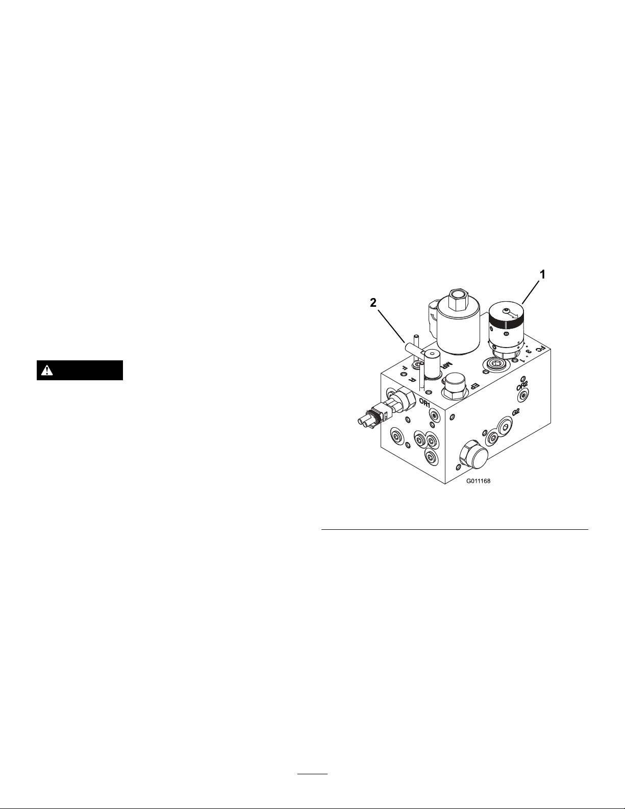
1.Locatethebypassvalveonthepump(Figure42)and
rotateit90°.
START.OutputLEDsmonitorrelayconditionindicatingthe
presenceofvoltageatoneofthreespecicoutputterminals.
Outputcircuitsdonotdetermineoutputdeviceintegrity,so
electricaltroubleshootingincludesoutputLEDinspection
andconventionaldeviceandwireharnessintegritytesting.
Measurethedisconnectedcomponentimpedance,the
impedancethroughwireharness(disconnectatSCM),orby
temporarily”testenergizing”thespeciccomponent.
TheSCMdoesnotconnecttoanexternalcomputerorhand
helddevice,cannotbere-programmed,anddoesnotrecord
intermittentfaulttroubleshootingdata.
ThedecalontheSCMonlyincludessymbols.ThreeLED
outputsymbolsareshownintheoutputbox.AllotherLEDs
areinputs.Thechartbelowidentiesthesymbols.
Figure42
1.Bypassvalve
2.Beforestartingtheengine,closethebypassvalveby
rotatingit90°(1/4turn).Donotstarttheenginewhile
thevalveisopen.
StandardControlModule (SCM)
TheStandardControlModuleisapottedelectronicdevice
producedinaone-size-ts-allconguration.Themodule
usessolidstateandmechanicalcomponentstomonitorand
controlstandardelectricalfeaturesrequiredforsafeproduct
operation.
Themodulemonitorsinputsincludingneutral,parkingbrake,
PTO,start,backlap,andhightemperature.Themodule
energizesoutputsincludingPTO,Starter,andETR(energize
torun)solenoid.
Themoduleisdividedintoinputsandoutputs.Inputsand
outputsareidentiedbygreenLEDindicatorsmountedon
theprintedcircuitboard.
Thestartcircuitinputisenergizedby12VDC.Allother
inputsareenergizedwhenthecircuitisclosedtoground.
EachinputhasaLEDthatisilluminatedwhenthespecic
circuitisenergized.UsetheinputLEDsforswitchandinput
circuittroubleshooting.
Figure43
HerearethelogicaltroubleshootingstepsfortheSCMdevice.
1.Determinetheoutputfaultyouaretryingtoresolve
(PTO,START,orETR).
2.MovethekeyswitchtotheOnpositionandensure
thattheredpowerLEDisilluminated.
3.MovealltheinputswitchestoensurethatallLEDs
changestate.
4.Positiontheinputdevicesattheappropriatepositionto
achievetheappropriateoutput.Usethefollowinglogic
charttodeterminetheappropriateinputcondition.
5.IfthespecicoutputLEDisilluminatedwithoutthe
appropriateoutputfunction,checktheoutputharness,
connections,andcomponent.Repairasneeded.
6.IfthespecicoutputLEDisnotilluminated,check
bothfuses.
7.IfthespecicoutputLEDisnotilluminatedandthe
inputsareintheappropriatecondition,installanew
SCManddetermineifthefaultdisappears.
Eachrow(across)inthelogicchartbelowidentiesinputand
outputrequirementsforeachspecicproductfunction.The
productfunctionsarelistedintheleftcolumn.Thesymbols
identifythespeciccircuitconditionincluding:energizedto
voltage,closedtoground,andopentoground.
Outputcircuitsareenergizedbyanappropriatesetofinput
conditions.ThethreeoutputsincludePTO,ETR,and
30

INPUTSOUTPUTS
FunctionPower
Start
Run(Off
Unit)
Run(On
Unit)
Mow
Backlap
HiTemp
ON
——
——
—
—
——
—
In
Neutral
StartON
OO
OO
Brake
ON
+
OOOOOOO
OO
O
OO
—
———
PTOONInSeat
O
—
•(–)Indicatesacircuitclosedtoground—LEDON.
•(O)Indicatesacircuitopentogroundorde-energized
—LEDOFF.
•(+)Indicatesanenergizedcircuit(clutchcoil,solenoid,or
startinput)—LEDON.
•ABlankindicatesacircuitthatisnotinvolvedwiththe
logic.
Totroubleshoot,turnonthekeywithoutstartingtheengine.
Identifythespecicfunctionthatdoesnotworkandwork
acrossthelogicchart.Inspecttheconditionofeachinput
LED’stoensurethatitmatchesthelogicchart.
—
—
OO
HiTempBacklap
OO
OOO
OOO
—
—
Start
++
O
OOO
ETR
+
+
++
++
PTO
O
O
O
IftheinputLEDsarecorrect,checktheoutputLED .Ifthe
outputLEDisilluminatedbutthedeviceisnotenergized,
measuretheavailablevoltageattheoutputdevice,the
continuityofthedisconnecteddevice,andthepotential
voltageonthegroundcircuit(oatingground).Repairswill
varydependingonyourndings.
31

OperatingTips
GeneralTipsforModel03171
DANGER
Themowerhasauniquetractionsystemthatwill
allowthemachinetomoveforwardonsidehills,
eveniftheuphillwheelshouldcomeoffofthe
ground.Ifthisshouldhappen,theoperatororany
bystanderscouldbeseriouslyinjuredorkilledina
rollover.
Theslopeangleatwhichthemachinewilltipis
dependentonmanyfactors.Amongtheseare
mowingconditionssuchaswetorundulatingturf,
speed(especiallyinturns),positionofthecutting
units(withSidewinder),tirepressure,andoperator
experience.
Atsidehillanglesof15degreesorless,theriskof
arolloverislow.Astheslopeangleincreasestoa
recommendedmaximumlimitof25degrees,the
riskofarolloverincreasestoamoderatelevel.
not ex ceed a 20 deg r ee side hill slope ang le because
the risk of a r ollo v er and serious injur y or death is
v er y high.
Todeterminewhichhillsorslopesyoumaysafely
operateon,youmustconductasitesurveyof
themowingarea.Whenperformingthissite
survey,alwaysusecommonsenseandtakeinto
considerationtheturfconditionandtherollover
risk.T odeterminewhichhillsorslopesmaybe
safelyoperatedon,usetheinclinometerprovided
witheachmachine.Toperformasitesurvey,laya
1.25mplank(4ft2x4)ontheslopesurfaceand
measuretheangleoftheslope.The1.25mplank
(4ft2x4)willaveragetheslopebutwillnottake
intoconsiderationdipsorholeswhichcancausea
suddenchangeinsidehillangle.
T he maximum
side hill ang le should not be g r eater than 20 deg r ees.
Additionally,themachineisequippedwithan
angleindicatormountedonthesteeringtube.This
indicatesthesidehillanglethemachineisonand
identiestherecommendedmaximumlimitof25
degrees.
Al w ays w ear y our seat belt.
•Practiceoperatingthemachineandbecomethoroughly
familiarwithit.
•Starttheengineandrunitathalfidleuntilitwarmsup.
Pushthethrottleleverallthewayforward,liftthecutting
units,disengagetheparkingbrake,presstheforward
tractionpedal,andcarefullydrivetoanopenarea.
Do
•Practicemovingforwardandreverse,andstartingand
stoppingthemachine.Tostop,takeyourfootoffofthe
tractionpedalandletitreturntoneutralorpressdown
onthereversepedaltostop.Goingdownahill,youmay
needtousethereversepedaltostop.
•Whendrivingonslopes,driveslowlytomaintainsteering
controlandavoidturnstopreventrollovers.Insidehill
situationsyoushouldshiftthesidewindercuttingunits
totheuphillsidetogiveyoumorestability.Conversely,
shiftingthecuttingunitstothedownhillsidewillgive
youlessstability.Thisshouldalwaysbedonebefore
goingonasidehill.
•Whenpossible,mowupanddownhillsratherthanacross
them.Havethecuttingunitsloweredwhengoingdowna
hilltomaintainsteeringcontrol.Donotattempttoturn
onahill.
•Practicedrivingaroundobstacleswiththecuttingunits
upanddown.Becarefulwhendrivingbetweennarrow
objectssothatyoudonotdamagethemachineorcutting
units.
•OntheSidewinderunit,getafeelforthereachofthe
cuttingunitssothatyoudonothangthemupordamage
theminanyway.
•Donotshifttheunitsfromsidetoside,unlessthecutting
unitsaredownandthemachineismoving,orthecutting
unitsareupinthetransportposition.Shiftingthecutting
unitswhentheyaredownandthemachineisnotmoving
maydamagetheturf.
•Alwaysdriveslowlyinroughareas.
•Ifapersonappearsinorneartheoperatingarea,stop
themachine,anddonotstartitagainuntiltheareais
cleared.Themachineisdesignedforoneperson.Never
letanyoneelserideonthemachinewithyou.Thisis
extremelydangerousandcouldresultinseriousinjury.
•Accidentscanhappentoanyone.Themostcommon
causesareexcessivespeed,suddenturns,terrain(not
knowingwhichslopesandhillscanbemowedsafely),not
stoppingtheenginebeforeleavingtheoperator’sseat,
anddrugsthatimpairyouralertness.Coldcapsulesor
prescriptiondrugsmaycausedrowsiness,ascanalcohol
andotherdrugs.Stayalertandstaysafe.Failuretodoso
couldresultinseriousinjury.
•TheSidewinderoffersuptoamaximumof33cm(13
inches)ofoverhang,allowingyoutotrimclosertothe
edgeofsandtrapsandotherobstacles,whileatthesame
timekeepingthetractortiresasfarawayfromtheedge
oftrapsorwaterhazardsaspossible.
•Ifanobstacleisintheway,shiftthecuttingunitstoeasily
mowaroundit.
•Whentransportingthemachinefromoneworkareato
another,raisethecuttingunitstothefullyupposition,
movethemow/transportslidetothelefttotransport,
andplacethethrottleintheFastposition.
32

GeneralTipsforModel03170
DANGER
Themowerhasauniquetractionsystemthatwill
allowthemachinetomoveforwardonsidehills,
eveniftheuphillwheelshouldcomeoffofthe
ground.Ifthisshouldhappen,theoperatororany
bystanderscouldbeseriouslyinjuredorkilledina
rollover.
Theslopeangleatwhichthemachinewilltipis
dependentonmanyfactors.Amongtheseare
mowingconditionssuchaswetorundulatingturf,
speed(especiallyinturns),positionofthecutting
units,tirepressure,andoperatorexperience.
Atsidehillanglesof20degreesorless,theriskof
arolloverislow.Astheslopeangleincreasestoa
recommendedmaximumlimitof25degrees,the
riskofarolloverincreasestoamoderatelevel.
not ex ceed a 25 deg r ee side hill slope ang le because
the risk of a r ollo v er and serious injur y or death is
v er y high.
Todeterminewhichhillsorslopesyoumaysafely
operateon,youmustconductasitesurveyof
themowingarea.Whenperformingthissite
survey,alwaysusecommonsenseandtakeinto
considerationtheturfconditionandtherollover
risk.T odeterminewhichhillsorslopesmaybe
safelyoperatedon,usetheinclinometerprovided
witheachmachine.Toperformasitesurvey,laya
1.25mplank(4ft2x4)ontheslopesurfaceand
measuretheangleoftheslope.The1.25mplank
(4ft2x4)willaveragetheslopebutwillnottake
intoconsiderationdipsorholeswhichcancausea
suddenchangeinsidehillangle.
T he maximum
side hill ang le should not be g r eater than 25 deg r ees.
Additionally,themachineisequippedwithan
angleindicatormountedonthesteeringtube.This
indicatesthesidehillanglethemachineisonand
identiestherecommendedmaximumlimitof25
degrees.
Al w ays w ear y our seat belt.
•Practiceoperatingthemachineandbecomethoroughly
familiarwithit.
•Starttheengineandrunitathalfidleuntilitwarmsup.
Pushthethrottleleverallthewayforward,liftthecutting
units,disengagetheparkingbrake,presstheforward
tractionpedal,andcarefullydrivetoanopenarea.
•Practicemovingforwardandreverse,andstartingand
stoppingthemachine.Tostop,takeyourfootoffofthe
tractionpedalandletitreturntoneutralorpressdown
Do
onthereversepedaltostop.Goingdownahill,youmay
needtousethereversepedaltostop.
•Whendrivingonslopes,driveslowlytomaintainsteering
controlandavoidturnstopreventrollovers.Insidehill
situationsyoushouldshiftthesidewindercuttingunits
totheuphillsidetogiveyoumorestability.Conversely,
shiftingthecuttingunitstothedownhillsidewillgive
youlessstability.Thisshouldalwaysbedonebefore
goingonasidehill.
•Whenpossible,mowupanddownhillsratherthanacross
them.Havethecuttingunitsloweredwhengoingdowna
hilltomaintainsteeringcontrol.Donotattempttoturn
onahill.
•Practicedrivingaroundobstacleswiththecuttingunits
upanddown.Becarefulwhendrivingbetweennarrow
objectssothatyoudonotdamagethemachineorcutting
units.
•OntheSidewinderunit,getafeelforthereachofthe
cuttingunitssothatyoudonothangthemupordamage
theminanyway.
•Donotshifttheunitsfromsidetoside,unlessthecutting
unitsaredownandthemachineismoving,orthecutting
unitsareupinthetransportposition.Shiftingthecutting
unitswhentheyaredownandthemachineisnotmoving
maydamagetheturf.
•Alwaysdriveslowlyinroughareas.
•Ifapersonappearsinorneartheoperatingarea,stop
themachine,anddonotstartitagainuntiltheareais
cleared.Themachineisdesignedforoneperson.Never
letanyoneelserideonthemachinewithyou.Thisis
extremelydangerousandcouldresultinseriousinjury.
•Accidentscanhappentoanyone.Themostcommon
causesareexcessivespeed,suddenturns,terrain(not
knowingwhichslopesandhillscanbemowedsafely),not
stoppingtheenginebeforeleavingtheoperator’sseat,
anddrugsthatimpairyouralertness.Coldcapsulesor
prescriptiondrugsmaycausedrowsiness,ascanalcohol
andotherdrugs.Stayalertandstaysafe.Failuretodoso
couldresultinseriousinjury.
•TheSidewinderoffersuptoamaximumof33cm(13
inches)ofoverhang,allowingyoutotrimclosertothe
edgeofsandtrapsandotherobstacles,whileatthesame
timekeepingthetractortiresasfarawayfromtheedge
oftrapsorwaterhazardsaspossible.
•Ifanobstacleisintheway,shiftthecuttingunitstoeasily
mowaroundit.
•Whentransportingthemachinefromoneworkareato
another,raisethecuttingunitstothefullyupposition,
movethemow/transportslidetothelefttotransport,
andplacethethrottleintheFastposition.
MowingTechniques
•Tobegincutting,engagethecuttingunits,thenapproach
themowingareaslowly.Oncethefrontcuttingunitsare
overthemowingarea,lowerthecuttingunits.
33

•Toachievetheprofessionalstraight-linecutandstriping
thatisdesirableforsomeapplications,ndatreeorother
objectinthedistanceanddrivestraighttowardit.
Important:Ifthereelspeedistooslow ,youmaynotice
visibleclipmarks.Ifthereelspeedistoofast,thecut
mayhaveafuzzyappearance.
•Assoonasthefrontcuttingunitsreachtheedgeofthe
mowingarea,liftthecuttingunitsandperformateardrop
shapedturntoquicklylineyouupforyournextpass.
•Tomowaroundbunkers,ponds,orothercontours
easily,usetheSidewinderandmovethecontrolleverleft
orright,dependingonyourmowingapplication.The
cuttingunitscanalsobeshiftedtovarytiretracking.
•Thecuttingunitstendtothrowgrasstothefrontorthe
rearofthemachine.Frontthrowshouldbeusedwhen
cuttingsmalleramountsofgrass;thus,leavingabetter
after-cutappearance.T othrowclippingstothefront,
simplyclosetherearshieldonthecuttingunits.
CAUTION
Topreventpersonalinjuryordamagetothe
machine,donotopenorclosethecuttingunit
shieldswhiletheengineisrunning.
Shutofftheengineandwaitforallmovingparts
tostopbeforeopeningorclosingthecuttingunit
shields.
•Whencuttinglargeramountsofgrass,positiontheshields
tojustbelowhorizontal.Donotopentheshieldstoo
faroranexcessiveamountofclippingscouldbuild
upontheframe,rearradiatorscreen,andengine
area.
Adjustthecliprate(reelspeed)asfollows:
1.Verifytheheight-of-cutsettingonthecuttingunits.
Usethecolumnofthechartlistingeither5or8reels,
andndtheheight-of-cutlistingnearesttheactual
height-of-cutsetting.Lookacrossthecharttondthe
numberthatcorrespondstothatheightofcut.
•Thecuttingunitsarealsoequippedwithbalanceweights
onthenon-motorendtogiveanevencut.Youcanadd
orremoveweightsifamismatchoccursonyourturf.
AfterMowing
Aftermowing,thoroughlywashthemachinewithagarden
hosewithoutanozzletopreventexcessivewaterpressure
frompreventcontaminationanddamagetothesealsand
bearings.Ensurethattheradiatorandoilcoolerarekept
freeofdirtorgrassclippings.Aftercleaning,inspectthe
machineforpossiblehydraulicuidleaks,damage,orwear
tothehydraulicandmechanicalcomponents.Checkthe
cuttingunitbladestoensurethattheyaresharpandthatthe
reel-to-bedknifecontactisproperlyadjusted.
Important:Afterwashingthemachine,movethe
Sidewindermechanismfromlefttorightseveraltimes
toremovethewaterbetweenthebearingblocksandthe
crosstube(model03170only).
SelectingtheClipRate(ReelSpeed)
Toachieveaconsistent,highqualityofcutandauniform
after-cutappearance,itisimportantthatthereelspeedbe
matchedtotheheightofcut.
34

REELSPEEDSELECTIONCHART
Height-of-Cut
5-BladeReel8-BladeReel
8kph
(5MPH)
9.6kph
(6MPH)
8kph
(5MPH)
9.6kph
(6MPH)
63.5
mm
60.32
mm
57.15
mm
53.97
mm
50.8
mm
47.62
mm
44.45
mm
41.27
mm
38.10
mm
34.92
mm
31.75
mm
28.75
mm
25.40
mm
22.22
mm
19.05
mm
15.87
mm
12.70
mm
9.52
mm
2-1/2
inches
2-3/8
inches
2-1/4
inches
2-1/8
inches
2inches34
1-7/8
inches
1-3/4
inches
1-5/8
inches
1-1/2
inches
1-3/8
inches
1-1/4
inches
1-1/8
inches
1inch9
7/8inch9*9*
3/4inch9*9*
5/8inch9*9*
1/2inch9*9*
3/8inch9*9*
33
34
34
34
4
4
5
57
5
6944
8
5
5
6
834
9*
9*
3*3*
3*3*
3*3*
3*3*
3*3*
3*3*
3*3*
3*3*
34
4
5
57
7
9
9
9
Figure44
1.Reelspeedcontrol2.Backlapcontrol
3.Operatethemachineforseveraldays,thenexaminethe
cuttoensurethequalityofcut.Thereelspeedknob
maybesetonepositiononeithersideoftheposition
indicatedonthecharttoaccountfordifferencesin
grasscondition,grasslengthremoved,andpersonal
preference.
5
6
9
9*
9*
9*
*Torodoesnotrecommendthisheight-of-cutand/or
mowingspeed.
Note:Thehigherthenumber,thehigherthespeed.
2.Turnthereelspeedcontrolknob(Figure44)tothe
numbersettingdeterminedinStep1.
35

Maintenance
Note:Determinetheleftandrightsidesofthemachine
fromthenormaloperatingposition.
RecommendedMaintenanceSchedule(s)
MaintenanceService
Interval
Afterthersthour
Aftertherst10hours
Aftertherst50hours
Beforeeachuseordaily
Every25hours
Every50hours
Every100hours
Every150hours
MaintenanceProcedure
•T orquethewheelnuts.
•T orquethewheelnuts.
•Checktheconditionandtensionofallbelts.
•Changethehydrauliclter.
•Changetheoilandoillter.
•Checktheengineoillevel.
•Checktheenginecoolantlevel.
•Checkthehydraulicuidlevel.
•Checkthetirepressure.
•Checkthereel-to-bedknifecontact.
•Checktheinterlocksystem.
•Drainthewaterseparator.
•Cleantheradiatorandoilcooler.
•Checkthehydrauliclinesandhoses.
•Checktheelectrolytelevel.(Ifmachineisinstorage,checkevery30days.)
•Lubricateallbearingsandbushings.(Lubricateallbearingsandbushingsdailywhen
conditionsaredustyanddirty.)
•Checktheconditionandtensionofallbelts.
•Changetheoilandoillter.
•T orquethewheelnuts.
Every200hours
Every400hours
Every500hours
Every2years
•Servicetheaircleaner(Morefrequentlyinextremedustyordirtyconditions)
•Checktheparkingbrakeadjustment.
•Changethehydrauliclter.
•Checkthefuellinesandconnections.
•Replacethefuelltercanister.
•Changethehydraulicuid.
•Greasethebearingsintherearaxle.
•Drainandcleanthefueltank.
•Drainandushthecoolantsystem(T aketoanauthorizedTorodealerorrefertothe
ServiceManual).
CAUTION
Ifyouleavethekeyintheignitionswitch,someonecouldaccidentlystarttheengineandseriouslyinjure
youorotherbystanders.
Removethekeyfromtheignitionbeforeyoudoanymaintenance.
36

DailyMaintenanceChecklist
Duplicatethispageforroutineuse.
Fortheweekof:
MaintenanceCheckItem
Checkthesafetyinterlock
operation.
Checkthebrakeoperation.
Checkthefuellevel.
Checktheengineoillevel.
Checkthecoolingsystem
uidlevel.
Drainthewater/fuel
separator.
Checktheairlter ,dustcup,
andburpvalve.
Checkforunusualengine
2
noises.
Checktheradiatorand
screenfordebris
Checkforunusualoperating
noises.
Checkthehydraulicsystem
oillevel.
Checkthehydraulichoses
fordamage.
Checkforuidleaks.
Checkthefuellevel.
Checkthetirepressure.
Checktheinstrument
operation.
Checkthereel-to-bedknife
contactadjustment.
Checktheheight-of-cut
adjustment.
Lubricateallthegrease
2
ttings.
Touch-upanydamagedpaint.
1
Checktheglowplugandinjectornozzlesifstartingishard,thereisexcesssmoke,orroughrunningisnoted.
2
Immediatelyaftereverywashing,regardlessoftheintervallisted.
Mon.T ues.Wed.Thurs.Fri.
Sat.Sun.
Important:Refertoyourengine
NotationforAreasofConcern
Inspectionperformedby:
ItemDate
Operator's Man ual
foradditionalmaintenanceprocedures.
Information
37
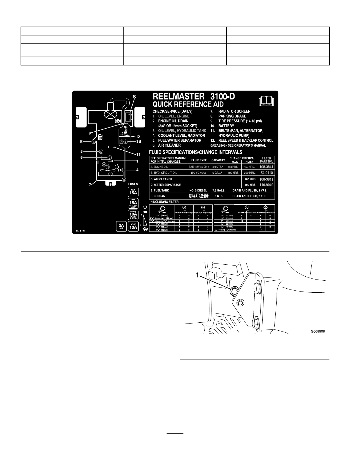
NotationforAreasofConcern(cont'd.)
ServiceIntervalChart
Premaintenance
Procedures
RemovingtheHood
Thehoodmaybeeasilyremovedtoeasemaintenance
proceduresintheengineareaofthemachine.
1.Unlatchandraisethehood.
2.Removethecotterpinthatsecuresthehoodpivotto
themountingbrackets(
Figure46).
Figure45
Figure46
1.Cotterpin
3.Slidethehoodtotherightside,lifttheotherside,and
pullitoutofthebrackets.
Note:Reversetheproceduretoinstallthehood.
38

Lubrication
GreasingtheBearingsAnd Bushings
ServiceInterval:Every50hours(Lubricateallbearingsand
bushingsdailywhenconditionsaredusty
anddirty.)
Every500hours/Yearly(whichevercomesrst)
Themachinehasgreasettingsthatmustbelubricated
regularlywithNo.2GeneralPurposeLithiumBaseGrease.
Bearingsandbushingsmustbelubricateddailywhenthe
operatingconditionsareextremelydustyanddirty.Dusty
anddirtyoperatingconditionscouldcausedirttogetinto
thebearingsandbushings,resultinginacceleratedwear.
Lubricatethegreasettingsimmediatelyaftereverywashing,
regardlessoftheintervalspecied.
Thegreasettinglocationsandquantitiesareasfollows:
Figure49
•Rearcuttingunitpivot(Figure47)
Figure47
•Frontcuttingunitpivot(Figure48)
•Steeringpivot(Figure50)
Figure50
•Rearliftarmpivotandliftcylinder(2)(Figure51)
Figure48
•SideWindercylinderends(2;model03170only)(Figure
49)
Figure51
39
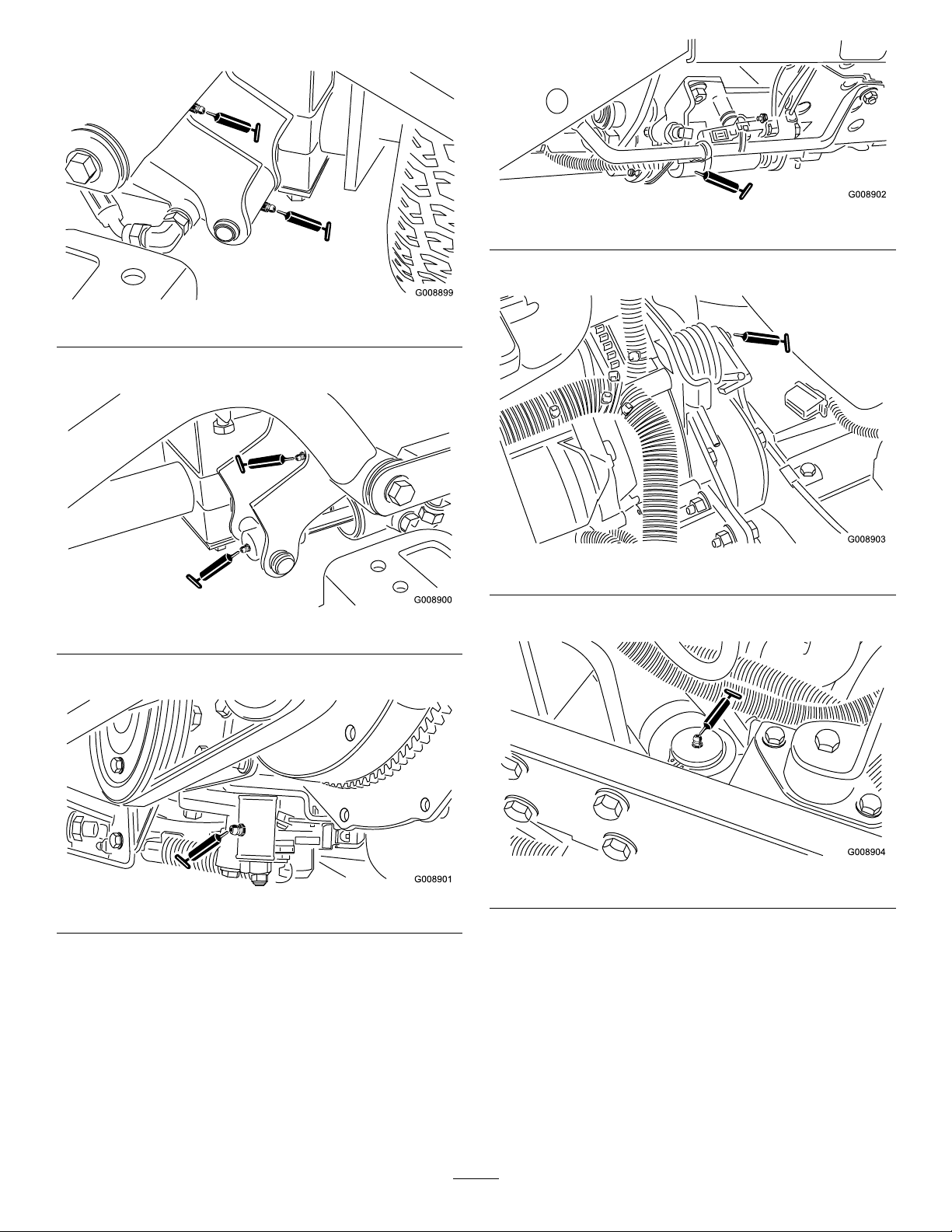
•Leftfrontliftarmpivotandliftcylinder(2)(Figure52)
Figure52
•Rightfrontliftarmpivotandliftcylinder(2)(Figure53)
Figure55
•Belttensionpivot(Figure56)
Figure53
•Neutraladjustmechanism(Figure54)
Figure54
•Mow/transportslide(Figure55)
Figure56
•Steeringcylinder(Figure57).
Figure57
Note:Ifdesired,installanadditionalgreasettingin
theotherendofthesteeringcylinder.Removethetire,
installthetting,greasethetting,removethetting,and
installtheplug(Figure58).
40

SealedBearings
Bearingsrarelyfailfromdefectsinmaterialsorworkmanship.
Themostcommonreasonforfailureismoistureand
contaminationworkingitswaypasttheprotectiveseals.
Bearingsthataregreasedwillrelyuponregularmaintenance
topurgeharmfuldebrisfromthebearingarea.Sealed
bearingsrelyonaninitialllofspecialgreaseandarobust
integralsealtokeepcontaminantsandmoistureoutofthe
rollingelements.
Figure58
Thesealedbearingsrequirenolubricationorshort-term
maintenance.Thisminimizesroutineservicerequired
andreducesthepotentialofturfdamageduetogrease
contamination.Thesesealedbearingpackageswillprovide
goodperformanceandlifeundernormaluse,butperiodic
inspectionsofbearingconditionandsealintegrityshould
beconductedtoavoiddowntime.Thesebearingsshould
beinspectedseasonallyandreplacedifdamagedorworn.
Bearingsshouldoperatesmoothlywithnodetrimental
characteristicssuchashighheat,noise,looseness,or
indicationsofcorrosion(rust).
Duetotheoperatingconditionsthesebearing/sealpackages
aresubjectto(i.e.,sand,turfchemicals,water,impacts,etc.)
theyareconsiderednormalwearitems.Bearingsthatfaildue
tocausesotherthandefectsinmaterialsorworkmanshipare
typicallynotcoveredunderthewarranty.
Note:Bearinglifecanbenegativelyaffectedbyimproper
wash-downprocedures.Donotwashdowntheunitwhenit
isstillhotandavoiddirectinghigh-pressureorhighvolume
sprayatthebearings.
41

EngineMaintenance
ServicingtheAirCleaner
ServiceInterval:Every200hours(Morefrequentlyin
extremedustyordirtyconditions)
•Checktheaircleanerbodyfordamagewhichcouldcause
anairleak.Replaceitifitisdamaged.Checkthewhole
intakesystemforleaks,damage,orloosehoseclamps.
•Servicetheaircleanerattherecommendedservice
intervalorearlierifengineperformancesuffersdueto
extremelydusty ,dirtyconditions.Changingtheairlter
beforeitisnecessaryonlyincreasesthechanceofdirt
enteringtheenginewhenthelterisremoved.
•Ensurethatthecoverisseatedcorrectlyandsealswith
theaircleanerbody.
Figure60
1.Primarylter
1.Releasethelatchesthatsecuretheaircleanercoverto
theaircleanerbody(Figure59).
Figure59
1.Aircleanercover2.Aircleanerlatch
2.Removethecoverfromtheaircleanerbody .
3.Beforeremovingthelter,uselow-pressureair(40psi,
cleananddry)tohelpremovelargeaccumulationsof
debrispackedbetweentheoutsideofprimarylterand
thecanister.Avoidusinghigh-pressureairwhichcould
forcedirtthroughthelterintotheintaketract.This
cleaningprocesspreventsdebrisfrommigratinginto
theintakewhenyouremovetheprimarylter.
4.Removeandreplacetheprimarylter(Figure60).
5.Inspectthenewlterforshippingdamageandcheck
thesealingendofthelterandthebody.Donotuse
adamagedelement.
6.Insertthenewlterbyapplyingpressuretotheouter
rimoftheelementtoseatitinthecanister.Donot
applypressuretotheexiblecenterofthelter.
7.Cleanthedirtejectionportlocatedintheremovable
cover.
8.Removetherubberoutletvalvefromthecover,clean
thecavity,andreplacetheoutletvalve.
9.Installthecoverorientingtherubberoutletvalveina
downwardposition—betweenapproximately5o'clock
to7o'clockwhenviewedfromtheend.
10.Securethecoverlatches.
ChangingtheEngineOiland Filter
ServiceInterval:Aftertherst50hours
Every150hours
1.Removeeitherdrainplug(Figure61)andlettheoil
owintoadrainpan;whentheoilstopsowing,install
thedrainplug.
Note:Cleaningtheusedelementmaydamagethe
ltermedia.
42

Figure61
1.Engineoildrainplug
2.Removetheoillter(Figure62).
FuelSystem
Maintenance
DANGER
Undercertainconditions,dieselfuelandfuelvapors
arehighlyammableandexplosive.Areoran
explosionfromfuelcanburnyouandothersand
cancausepropertydamage.
•Useafunnelandllthefueltankoutdoors,in
anopenarea,whentheengineisoffandiscold.
Wipeupanyfuelthatspills.
•Donotllthefueltankcompletelyfull.Add
fueltothefueltankuntilthelevelis6to13mm
(1/4to1/2inch)belowthebottomoftheller
neck.Thisemptyspaceinthetankallowsthe
fueltoexpand.
•Neversmokewhenhandlingfuel,andstayaway
fromanopenameorwherefuelfumesmaybe
ignitedbyaspark.
Figure62
1.Engineoillter
3.Applyalightcoatofcleanoiltothenewltersealand
installtheoillter.Donotovertighten0.
4.Addoiltothecrankcase;refertoCheckingtheEngine
OilLevel.
•Storefuelinaclean,safety-approvedcontainer,
andkeepthecapinplace.
ServicingtheFuelTank
ServiceInterval:Every2years—Drainandcleanthefuel
tank.
Drainandcleanthetankifthefuelsystembecomes
contaminatedorifthemachinewillbestoredforanextended
periodoftime.Usecleanfueltoushoutthetank.
InspectingtheFuelLinesand Connections
ServiceInterval:Every400hours/Yearly(whichevercomes
rst)
Inspectthefuellinesandconnectionsfordeterioration,
damage,orlooseconnections.
DrainingtheWaterSeparator
ServiceInterval:Beforeeachuseordaily
1.Placeacleancontainerunderthefuellter.
2.Loosenthedrainvalveonthebottomofthelter
canister(
43
Figure63).

G009880
1
2
3
Figure63
2.MovethethrottletotheFastposition.
3.TurnthekeyinthekeyswitchtotheStartpositionand
watchthefuelowaroundtheconnector.Turnthekey
totheOffpositionwhenyouseeasolidow.
4.Tightenthepipeconnectorsecurely.
5.Repeatthisprocedureontheremainingnozzles.
1.Waterseparator/lter
canister
2.Ventplug
3.Tightenthevalveafterdraining.
3.Drainvalve
ChangingtheFuelFilter Canister
ServiceInterval:Every400hours
1.Cleantheareawheretheltercanistermounts(Figure
63).
2.Removetheltercanisterandcleanthemounting
surface.
3.Lubricatethegasketontheltercanisterwithcleanoil.
4.Installtheltercanisterbyhanduntilthegasket
contactsthemountingsurface;thenrotateanadditional
1/2turn.
BleedingAirfromtheInjectors
Note:Thisprocedureshouldbeusedonlyifthefuelsystem
hasbeenpurgedofairthroughnormalprimingprocedures
andtheenginewillnotstart;refertoBleedingtheFuel
System.
1.LoosenthepipeconnectiontotheNo.1nozzleand
holderassembly.
Figure64
1.Fuelinjectors
44

ElectricalSystem
Maintenance
Keepthetopofthebatterycleanbywashingitperiodically
withabrushdippedinammoniaorbicarbonateofsoda
solution.Flushthetopsurfacewithwateraftercleaning.Do
notremovethellercapswhilecleaning.
CaringfortheBattery
ServiceInterval:Every25hours—Checktheelectrolyte
level.(Ifmachineisinstorage,check
every30days.)
WARNING
CALIFORNIA
Proposition65Warning
Batteryposts,terminals,andrelated
accessoriescontainleadandleadcompounds,
chemicalsknowntotheStateofCalifornia
tocausecancerandreproductiveharm.
W ash hands after handling .
Thebatteryelectrolytelevelmustbeproperlymaintainedand
thetopofthebatterykeptclean.Ifthemachineisstoredina
locationwheretemperaturesareextremelyhigh,thebattery
willrundownmorerapidlythanifthemachineisstoredin
alocationwheretemperaturesarecool.
DANGER
Thebatterycablesmustbetightontheterminalstoprovide
goodelectricalcontact.
WARNING
Incorrectbatterycableroutingcoulddamagethe
tractorandcablescausingsparks.Sparkscancause
thebatterygassestoexplode,resultinginpersonal
injury.
•Always
cablebeforedisconnectingthepositive(red)
cable.
•Always
beforeconnectingthenegative(black)cable.
Ifcorrosionoccursattheterminals,disconnectthecables,
negative(–)cablerst,andscrapetheclampsandterminals
separately.Connectthecables,positive(+)cablerst,and
coattheterminalswithpetroleumjelly.
Important:Alwaysdisconnectthebatterycables,
groundcable(–)rst,topreventpossiblewiringdamage
fromshortoutswheneverworkingwiththeelectrical
system.
disconnect
connect
thenegative(black)battery
thepositive(red)batterycable
Batteryelectrolytecontainssulfuricacidwhichisa
deadlypoisonandcausessevereburns.
•Donotdrinkelectrolyteandavoidcontactwith
skin,eyesorclothing.Wearsafetyglassesto
shieldyoureyesandrubberglovestoprotect
yourhands.
•Fillthebatterywherecleanwaterisalways
availableforushingtheskin.
•Chargethebatteryinawell-ventilatedplaceso
thatthegassesproducedwhilechargingcan
dissipate.
•Sincethegasesareexplosive,keepopenames
andelectricalsparksawayfromthebattery;do
notsmoke.
•Nauseamayresultifthegasesareinhaled.
•Unplugthechargerfromtheelectricaloutlet
beforeconnectingtoordisconnectingthe
chargerleadsfromthebatteryposts.
Maintainthecelllevelwithdistilledordemineralizedwater.
Donotllthecellsabovethebottomofthesplitringinside
eachcell.Installthellercapswiththeventspointingtothe
rear(towardthefueltank).
StoringtheBattery
Ifthemachinewillbestoredmorethan30days,removethe
batteryandchargeitfully.Eitherstoreitontheshelforonthe
machine.Leavethecablesdisconnectediftheyarestoredon
themachine.Storethebatteryinacoolatmospheretoavoid
quickdeteriorationofthechargeinthebattery.Toprevent
thebatteryfromfreezing,ensurethatitisfullycharged.The
specicgravityofafullychargedbatteryis1.265–1.299.
Fuses
Thefusesarelocatedunderconsolecoverofthemachine.
45

DriveSystem
CoolingSystem
Maintenance
AdjustingtheTractionDrive forNeutral
Ifthemachinemoveswhenthetractionpedalisintheneutral
position,adjustthetractioncam.
1.Parkthemachineonalevelsurfaceandturntheengine
off.
2.Raiseonefrontwheelandonerearwheelofftheoor
andplacesupportblocksundertheframe.
Note:Onefrontwheelandrearwheelmustberaised
offthegroundorthemachinewillmoveduringthe
adjustment.
3.Loosenlocknutontractionadjustmentcam(Figure65).
Maintenance
CleaningtheEngineCooling System
ServiceInterval:Beforeeachuseordaily
Removedebrisfromtheoilcoolerandradiatordaily.Clean
themmorefrequentlyindirtyconditions.
1.Turntheengineoffandraisethehood.
2.Cleantheengineareathoroughlyofalldebris.
3.Removetheaccesspanel(
Figure66).
Figure65
1.Tractionadjustmentcam2.Locknut
4.Starttheengineandrotatethecamhexinboth
directionstodeterminemid-positionofneutralspan.
5.Tightenthelocknutthatsecurestheadjustment.
6.Stoptheengine.
7.Removethesupportblocksandlowerthemachineto
theshopoor.Testdrivethemachinetoensurethatit
doesnotcreep.
Figure66
1.Accesspanel3.Radiator
2.Oilcooler
4.Unlatchtheoilcoolerandpivotitrearward(Figure67).
Figure67
5.Cleanbothsidesoftheoilcoolerandradiatorarea
thoroughlywithwaterorcompressedair.
6.Pivottheoilcoolerbackintoposition.
7.Installtheaccesspanelandclosethehood.
46

BrakeMaintenance
BeltMaintenance
AdjustingtheParkingBrake
ServiceInterval:Every200hours—Checktheparkingbrake
adjustment.
1.Loosenthesetscrewthatsecurestheknobtothe
parkingbrakelever(Figure68).
Figure68
1.Parkingbrakelever
2.Knob
3.Setscrew
ServicingtheEngineBelts
ServiceInterval:Aftertherst10hours—Checkthe
conditionandtensionofallbelts.
Every100hours—Checktheconditionandtension
ofallbelts.
TensioningtheAlternator/FanBelt
1.Openthehood.
2.Checkthetensionbydepressingthealternator/fanbelt
midwaybetweenthealternatorandcrankshaftpulleys
with30N-m(22lb)offorce(Figure69).
Note:Thebeltshoulddeect11mm(7/16inch).
2.Rotatetheknobuntilyouproduceaforceof41–68
N-m(30–40lb)neededtoactuatethelever.
3.Tightenthesetscrewafterattainingtheadjustment.
Figure69
1.Alternator/fanbelt
3.Ifthedeectionisincorrect,completethefollowing
proceduretotensionthebelt:
A.Loosentheboltthatsecuresthebracetothe
engineandtheboltthatsecuresthealternatorto
thebrace.
B.Insertaprybarbetweenthealternatorandthe
engineandpryoutonthealternator.
C.Whenyouachievetheproperbelttension,tighten
thealternatorandbraceboltstosecurethe
adjustment.
ReplacingtheHydrostatDriveBelt
1.Insertanutdriverorsmallpieceoftubingontothe
endofthebelttensioningspring.
WARNING
Usecautionwhende-tensioningthespring,as
itisunderaheavyload.
2.Pushdownandforwardonthespringend(Figure70)
tounhookitfromthebracketandreleasetensionon
thespring.
47

Figure70
ControlsSystem
Maintenance
AdjustingtheThrottle
1.Positionthethrottleleverrearwardsothatitstops
againstthecontrolpanelslot.
2.Loosenthethrottlecableconnectorontheinjection
pumpleverarm(
Figure71).
1.Hydrostatdrivebelt
3.Replacethebelt.
4.Reversetheproceduretotensionthespring.
2.Springend
Figure71
1.Injectionpumpleverarm
3.Holdtheinjectionpumpleverarmagainstthelowidle
stopandtightenthecableconnector.
4.Loosenthescrewssecuringthethrottlecontroltothe
controlpanel.
5.Pushthethrottlecontrolleverallthewayforward.
6.Slidethestopplateuntilitcontactsthethrottlelever,
andtightenthescrewsthatsecurethethrottlecontrol
tothecontrolpanel.
7.Ifthethrottledoesnotstayinpositionduring
operation,torquethelocknutusedtosetthefriction
deviceonthethrottleleverto5–6N-m(40–55inch-lb).
Note:Themaximumforcerequiredtooperatethe
throttlelevershouldbe27N-m(20lb).
48
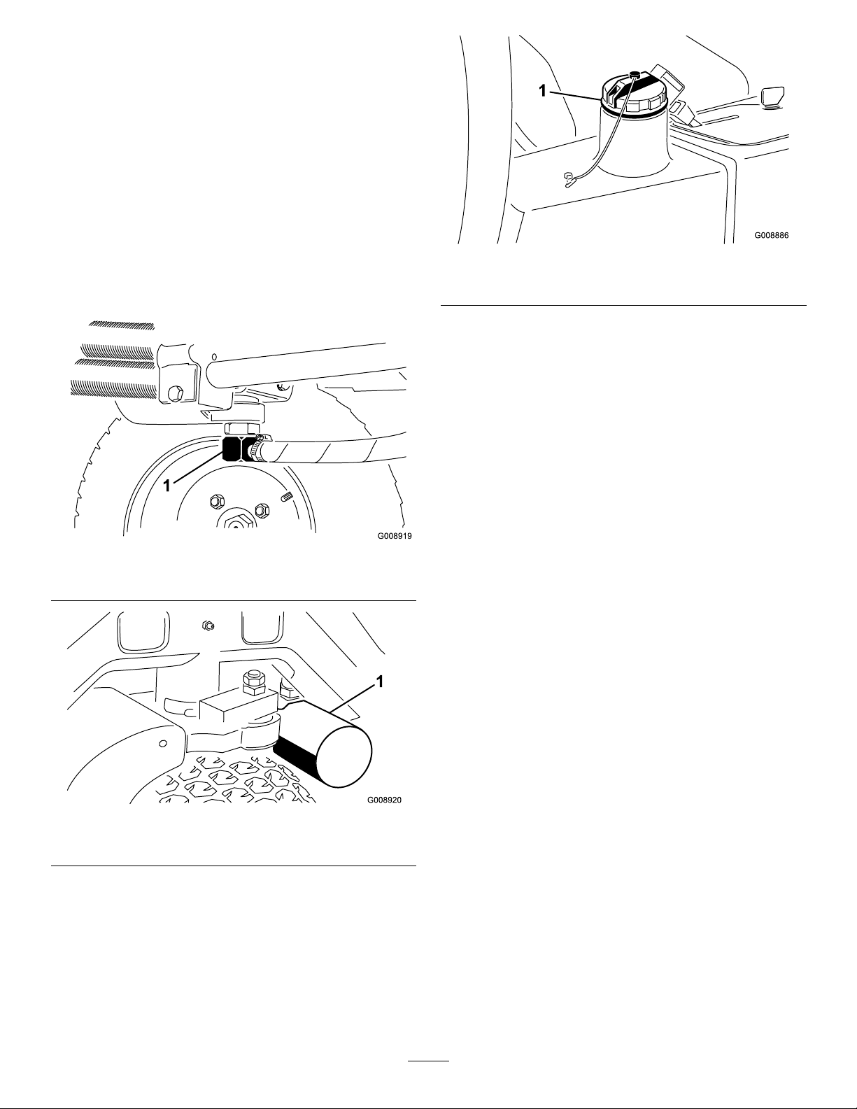
HydraulicSystem
Maintenance
ChangingtheHydraulicFluid
ServiceInterval:Every400hours
Iftheuidbecomescontaminated,contactaTorodistributor
toushthehydraulicsystem.Contaminatedhydraulicuid
looksmilkyorblackwhencomparedtocleanuid.
1.Turntheengineoffandraisethehood.
2.Disconnectthehydraulicline(Figure72)orremovethe
hydrauliclter(Figure73)andletthehydraulicuid
owintoadrainpan.
Figure72
1.Hydraulicline
Figure74
1.Hydraulicllcap
5.Installthereservoircap,starttheengine,anduseallof
thehydrauliccontrolstodistributethehydraulicuid
throughoutthesystem.
6.Checkforleaks;thenstoptheengine.
7.Checktheuidlevelandaddenoughtoraisethelevel
toFullmarkonthedipstick.Donotoverll.
ChangingtheHydraulicFilter
ServiceInterval:Aftertherst10hours
Every200hours/Yearly(whichevercomesrst)
UseagenuineTororeplacementlter(PartNo.54-0110).
Important:Usinganyotherltermayvoidthewarranty
onsomecomponents.
1.Positionthemachineonalevelsurface,lowerthe
cuttingunits,stoptheengine,engagetheparkingbrake,
andremovethekeyfromtheignitionswitch.
Figure73
1.Hydrauliclter
3.Installthehydrauliclinewhenhydraulicuidstops
draining.
4.Fillthereservoir(Figure74)withapproximately13.2
liters(3.5U .S.gallons)ofhydraulicuid;referto
CheckingtheHydraulicSystem.
Important:Useonlythehydraulicuids
specied.Otheruidscoulddamagethehydraulic
system.
2.Pinchoffthehosetotheltermountingplate.
3.Cleanaroundtheltermountingarea.
4.Placeadrainpanunderthelter(Figure73)and
removethelter.
5.Lubricatethenewltergasketandllthelterwith
hydraulicuid.
6.Ensurethattheltermountingareaisclean,screwthe
lteronuntilthegasketcontactsthemountingplate,
andthentightenthelter1/2turn.
7.Releasethehosetotheltermountingplate.
8.Starttheengineandletitrunforabouttwominutesto
purgetheairfromthesystem.
9.Stoptheengineandcheckforleaks.
49

CheckingtheHydraulicLines
Miscellaneous
andHoses
ServiceInterval:Beforeeachuseordaily
Checkhydrauliclinesandhosesforleaks,kinkedlines,loose
mountingsupports,wear,loosettings,weatherdeterioration,
andchemicaldeterioration.Makeallnecessaryrepairsbefore
operating.
WARNING
Hydraulicuidescapingunderpressurecan
penetrateskinandcauseinjury.
•Ensurethatallhydraulicuidhosesandlinesare
ingoodconditionandallhydraulicconnections
andttingsaretightbeforeapplyingpressureto
thehydraulicsystem.
•Keepyourbodyandhandsawayfrompin
holeleaksornozzlesthatejecthigh-pressure
hydraulicuid.
•Usecardboardorpapertondhydraulicleaks.
•Safelyrelieveallpressureinthehydraulicsystem
beforeperforminganyworkonthehydraulic
system.
•Seekimmediatemedicalattentionifuidis
injectedintoskin.
Maintenance
BacklappingtheCutting System
DANGER
Contactingthereelsmaycausepersonalinjuryor
death.
•Neverplaceyourhandsorfeetinthereelarea
whiletheengineisrunning.
•Whilebacklapping,thereelsmaystallandthen
startagain.
•Donotattempttostartreelsagainwithyour
handorfoot.
•Donotadjustthereelswhiletheengineis
running.
•Ifthereelstalls,stoptheenginebefore
attemptingtoclearthereel.
1.Positionthemachineonacleanandlevelsurface,lower
thecuttingunits,stoptheengine,engageparkingbrake,
andremovethekeyfromtheignitionswitch.
2.Removetheconsolecovertoexposethecontrols.
3.Rotatethebacklapcontroltothebacklapposition(R).
Rotatethereelspeedcontroltoposition1(Figure75).
Figure75
1.Reelspeedcontrol2.Backlapcontrol
Note:Theseatswitchisbypassedwhenthebacklap
controlisinthebacklapposition.Theoperatordoes
notneedtobeintheseat,buttheparkingbrakemust
beengagedortheenginewillnotrun.
50

Important:Donotrotatethebacklapcontrol
fromthemowpositiontothebacklapposition
whileengineisrunning.Otherwise,youmay
damagethereels.
Storage
PreparationforSeasonal
4.Maketheinitialreel-to-bedknifeadjustments
appropriateforbacklappingonallcuttingunits.Start
theengineandsetittolowidlespeed.
5.EngagethereelsbyengagingthePTOswitchonthe
controlpanel.
6.Applylappingcompoundwithlong-handledbrush.
7.Toadjustthecuttingunitswhilebacklapping,disengage
thereelsandturntheengineoff.Afteryouhavemade
theadjustments,repeatsteps4through6
8.Afterbacklapping,stoptheengine,rotatethebacklap
controltotheMowposition(F),setthereelspeed
controlstothedesiredmowingsetting,andwashallthe
lappingcompoundoffthecuttingunits.
Note:Additionalinstructionsandprocedureson
backlappingareavailableintheTOROSharpening
Reel&RotaryMowersManualFormNo.80–300SL.
Note:Forabettercuttingedge,runaleacross
thefrontfaceofthebedknifeafterlapping.Thiswill
removeanyburrsorroughedgesthatmayhavebuilt
uponthecuttingedge.
Storage
Followtheseproceduresanytimeyouwillbestoringthe
machineformorethan30days.
TractionUnit
1.Thoroughlycleanthetractionunit,cuttingunits,and
engine.
2.Checkthetirepressure.Inatealltiresto97to110
kPa(14to18psi).
3.Checkforloosefastenersandtightenthemasnecessary.
4.Greaseoroilallgreasettingsandpivotpoints.Wipe
upanyexcesslubricant.
5.Lightlysandandusetouch-uppaintonpaintedareas
thatarescratched,chipped,orrusted.Repairanydents
inthemetalbody.
6.Servicethebatteryandcablesasfollows:
A.Removethebatteryterminalsfromthebattery
posts.
B.Removethebattery.
C.Slowlychargethebatterybeforestorageandevery
60daysthereafterfor24hourstopreventlead
sulfationofthebattery.
Note:T opreventthebatteryfromfreezing,
ensurethatitisfullycharged.Thespecicgravity
ofafullychargedbatteryis1.265–1.299.
D.Cleanthebattery,terminals,andpostswithawire
brushandbakingsodasolution.
E.Coatthecableterminalsandbatterypostswith
Grafo112Xskin-overgrease(ToroPartNo.
505-47)orpetroleumjellytopreventcorrosion.
F.Eitherstorethebatteryontheshelforon
themachineinacoolarea.Leavethecables
disconnectedifthebatteryisstoredonthe
machine.
Engine
1.Draintheengineoilfromtheoilpanandreplacethe
drainplug.
2.Removeanddiscardtheoillter.
3.Installanewoillter.
4.Filltheoilpanwithapproximately3.8liters(4quarts)
ofSAE15W-40motoroil.
5.Starttheengineandrunitatidlespeedfor
approximatelytwominutes.
6.Stoptheengine.
51

7.Thoroughlydrainallthefuelfromthefueltank,fuel
lines,fuellter,andwaterseparatorassembly.
8.Flushthefueltankwithfresh,cleandieselfuel.
9.Secureallfuelsystemttings.
10.Thoroughlycleanandservicetheaircleanerassembly.
11.Sealtheaircleanerinletandtheexhaustoutletwith
weatherprooftape.
12.Checkanti-freezeprotectionandaddasneededforthe
expectedminimumtemperatureinyourarea.
52

Notes:
53

Notes:
54

Notes:
55

TheToroTotalCoverageGuarantee
ALimitedWarranty
ConditionsandProductsCovered
TheToroCompanyanditsafliate,ToroWarrantyCompany ,pursuant
toanagreementbetweenthem,jointlywarrantyourToroCommercial
product(“Product”)tobefreefromdefectsinmaterialsorworkmanship
fortwoyearsor1500operationalhours*,whicheveroccursrst.This
warrantyisapplicabletoallproductswiththeexceptionofAerators
(refertoseparatewarrantystatementsfortheseproducts).Wherea
warrantableconditionexists,wewillrepairtheProductatnocosttoyou
includingdiagnostics,labor,parts,andtransportation.Thiswarranty
beginsonthedatetheProductisdeliveredtotheoriginalretailpurchaser.
*Productequippedwithanhourmeter.
InstructionsforObtainingWarrantyService
YouareresponsiblefornotifyingtheCommercialProductsDistributoror
AuthorizedCommercialProductsDealerfromwhomyoupurchasedthe
Productassoonasyoubelieveawarrantableconditionexists.Ifyouneed
helplocatingaCommercialProductsDistributororAuthorizedDealer,or
ifyouhavequestionsregardingyourwarrantyrightsorresponsibilities,
youmaycontactusat:
ToroCommercialProductsServiceDepartment
ToroWarrantyCompany
811 1LyndaleAvenueSouth
Bloomington,MN55420-1196
952–888–8801or800–952–2740
E-mail:commercial.warranty@toro.com
OwnerResponsibilities
AstheProductowner,youareresponsibleforrequiredmaintenance
andadjustmentsstatedinyourOperator'sManual.Failuretoperform
requiredmaintenanceandadjustmentscanbegroundsfordisallowinga
warrantyclaim.
ItemsandConditionsNotCovered
Notallproductfailuresormalfunctionsthatoccurduringthewarranty
periodaredefectsinmaterialsorworkmanship.Thiswarrantydoesnot
coverthefollowing:
•Productfailureswhichresultfromtheuseofnon-Tororeplacement
parts,orfrominstallationanduseofadd-on,ormodiednon-T oro
brandedaccessoriesandproducts.Aseparatewarrantymaybe
providedbythemanufactureroftheseitems.
•Productfailureswhichresultfromfailuretoperformrecommended
maintenanceand/oradjustments.Failuretoproperlymaintainyour
ToroproductpertheRecommendedMaintenancelistedinthe
Operator’sManualcanresultinclaimsforwarrantybeingdenied.
•ProductfailureswhichresultfromoperatingtheProductinan
abusive,negligent,orrecklessmanner.
•Partssubjecttoconsumptionthroughuseunlessfoundtobe
defective.Examplesofpartswhichareconsumed,orusedup,
duringnormalProductoperationinclude,butarenotlimitedto,brake
padsandlinings,clutchlinings,blades,reels,rollersandbearings
(sealedorgreasable),bedknives,sparkplugs,castorwheelsand
bearings,tires,lters,belts,andcertainsprayercomponentssuchas
diaphragms,nozzles,andcheckvalves,etc.
•Failurescausedbyoutsideinuence.Conditionsconsideredtobe
outsideinuenceinclude,butarenotlimitedto,weather,storage
practices,contamination,useofunapprovedfuels,coolants,
lubricants,additives,fertilizers,water,orchemicals,etc.
•Failureorperformanceissuesduetotheuseoffuels(e.g.gasoline,
diesel,orbiodiesel)thatdonotconformtotheirrespectiveindustry
standards.
•Normalnoise,vibration,wearandtear,anddeterioration.
•Normal“wearandtear”includes,butisnotlimitedto,damageto
seatsduetowearorabrasion,wornpaintedsurfaces,scratched
decalsorwindows,etc.
Parts
Partsscheduledforreplacementasrequiredmaintenancearewarranted
fortheperiodoftimeuptothescheduledreplacementtimeforthatpart.
Partsreplacedunderthiswarrantyarecoveredforthedurationofthe
originalproductwarrantyandbecomethepropertyofT oro.T orowill
makethenaldecisionwhethertorepairanyexistingpartorassemblyor
replaceit.T oromayuseremanufacturedpartsforwarrantyrepairs.
DeepCycleandLithium-IonBatteryWarranty:
DeepcycleandLithium-Ionbatterieshaveaspeciedtotalnumberof
kilowatt-hourstheycandeliverduringtheirlifetime.Operating,recharging,
andmaintenancetechniquescanextendorreducetotalbatterylife.Asthe
batteriesinthisproductareconsumed,theamountofusefulworkbetween
chargingintervalswillslowlydecreaseuntilthebatteryiscompletelyworn
out.Replacementofwornoutbatteries,duetonormalconsumption,
istheresponsibilityoftheproductowner.Batteryreplacementmaybe
requiredduringthenormalproductwarrantyperiodatowner’sexpense.
Note:(Lithium-Ionbatteryonly):ALithium-Ionbatteryhasapartonly
proratedwarrantybeginningyear3throughyear5basedonthetime
inserviceandkilowatthoursused.RefertotheOperator'sManualfor
additionalinformation.
MaintenanceisatOwner’sExpense
Enginetune-up,lubrication,cleaningandpolishing,replacementoflters,
coolant,andcompletingrecommendedmaintenancearesomeofthe
normalservicesT oroproductsrequirethatareattheowner’sexpense.
GeneralConditions
RepairbyanAuthorizedT oroDistributororDealerisyoursoleremedy
underthiswarranty.
NeitherTheToroCompanynorToroWarrantyCompanyisliablefor
indirect,incidentalorconsequentialdamagesinconnectionwiththe
useoftheToroProductscoveredbythiswarranty ,includingany
costorexpenseofprovidingsubstituteequipmentorserviceduring
reasonableperiodsofmalfunctionornon-usependingcompletion
ofrepairsunderthiswarranty.ExceptfortheEmissionswarranty
referencedbelow,ifapplicable,thereisnootherexpresswarranty .
Allimpliedwarrantiesofmerchantabilityandtnessforuseare
limitedtothedurationofthisexpresswarranty .
Somestatesdonotallowexclusionsofincidentalorconsequential
damages,orlimitationsonhowlonganimpliedwarrantylasts,sothe
aboveexclusionsandlimitationsmaynotapplytoyou.Thiswarranty
givesyouspeciclegalrights,andyoumayalsohaveotherrightswhich
varyfromstatetostate.
Noteregardingenginewarranty:
TheEmissionsControlSystemonyourProductmaybecoveredby
aseparatewarrantymeetingrequirementsestablishedbytheU.S.
EnvironmentalProtectionAgency(EPA)and/ortheCaliforniaAir
ResourcesBoard(CARB).Thehourlimitationssetforthabovedonot
applytotheEmissionsControlSystemWarranty.RefertotheEngine
EmissionControlWarrantyStatementsuppliedwithyourproductor
containedintheenginemanufacturer’sdocumentationfordetails
CountriesOtherthantheUnitedStatesorCanada
CustomerswhohavepurchasedT oroproductsexportedfromtheUnitedStatesorCanadashouldcontacttheirT oroDistributor(Dealer)toobtain
guaranteepoliciesforyourcountry ,province,orstate.IfforanyreasonyouaredissatisedwithyourDistributor'sserviceorhavedifcultyobtaining
guaranteeinformation,contacttheT oroimporter.
374-0253RevB
 Loading...