


FormNo.3448-560RevA
HoverPro
HoverPro
MáquinaHoverPro
TondeuseHoverPro
HoverPro
®
550Machine
02617
®
550-Maschine
02617
®
550
02617
®
550
02617
®
550machine
02617
www.T oro.com.
*3448-560*


FormNo.3448-536RevA
HoverPro
ModelNo.02617—SerialNo.400000000andUp
®
550Machine
Registeratwww.T oro.com.
OriginalInstructions(EN)
*3448-536*

ThisproductcomplieswithallrelevantEuropean
directives.Fordetails,seetheseparateproduct
specicDeclarationofConformity(DOC)sheet.
GrossorNetTorque:Thegrossornettorque
ofthisenginewaslaboratoryratedbytheengine
manufacturerinaccordancewiththeSocietyof
AutomotiveEngineers(SAE)J1940orJ2723.As
conguredtomeetsafety,emission,andoperating
requirements,theactualenginetorqueonthisclass
ofmowerwillbesignicantlylower.Pleasereferto
theenginemanufacturer’sinformationincludedwith
themachine.
Introduction
Thismachineisintendedtobeusedbyhired,
commercialoperatorsandresidentialhomeownersfor
maintainingturfonslopes,tightundulations,areas
nearwater,orbunkerlips.Usingthisproductfor
purposesotherthanitsintendedusecouldprove
dangeroustoyouandbystanders.
Readthisinformationcarefullytolearnhowtooperate
andmaintainyourproductproperlyandtoavoid
injuryandproductdamage.Youareresponsiblefor
operatingtheproductproperlyandsafely .
Visitwww.https://www.toro.com/en-GBformore
information,includingsafetytips,trainingmaterials,
accessoryinformation,helpndingadealer,orto
registeryourproduct.
Wheneveryouneedservice,genuineToroparts,or
additionalinformation,contactanAuthorizedService
DealerorToroCustomerServiceandhavethemodel
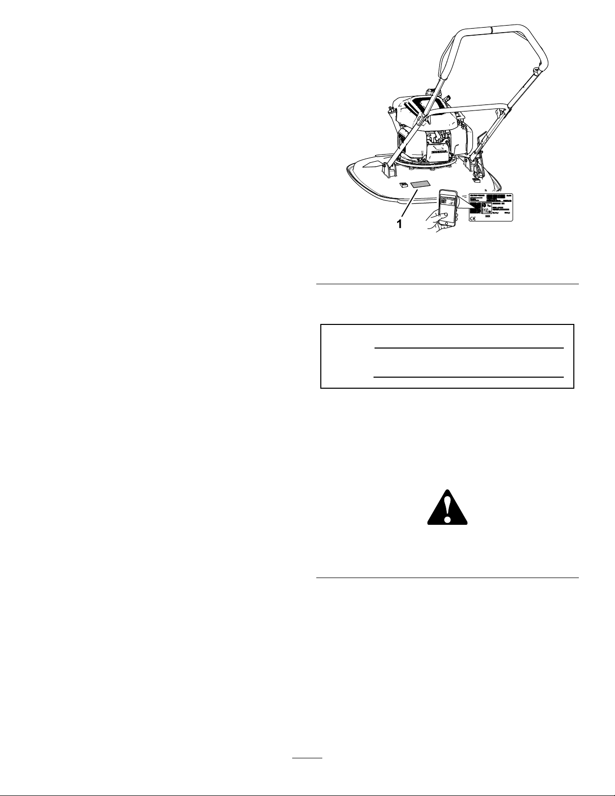
andserialnumbersofyourproductready.Figure1
identiesthelocationofthemodelandserialnumbers
ontheproduct.Writethenumbersinthespace
provided.
g364631
Figure1
1.Modelandserialnumberlocation
Writetheproductmodelandserialnumbersinthe
spacebelow:
ModelNo.
SerialNo.
Thismanualidentiespotentialhazardsandhas
safetymessagesidentiedbythesafety-alertsymbol
(Figure2),whichsignalsahazardthatmaycause
seriousinjuryordeathifyoudonotfollowthe
recommendedprecautions.
g000502
Figure2
Safety-alertsymbol
Important:Withyourmobiledevice,youcan
scantheQRcodeontheserialnumberdecal(if
equipped)toaccesswarranty,parts,andother
productinformation.
©2021—TheToro®Company
8111LyndaleAvenueSouth
Bloomington,MN55420
Thismanualuses2wordstohighlightinformation.
Importantcallsattentiontospecialmechanical
informationandNoteemphasizesgeneralinformation
worthyofspecialattention.
2
Contactusatwww.Toro.com.
PrintedintheUK
AllRightsReserved

Contents
Safety
Safety.......................................................................3
GeneralSafety...................................................3
SafetyandInstructionalDecals..........................4
Setup........................................................................5
1InstallingtheHandlebarFootstop.....................5
2InstallingtheHandlebar...................................5
3AddingOiltotheEngine...................................8
ProductOverview.....................................................9
Controls...........................................................10
Specications..................................................10
Attachments/Accessories.................................10
BeforeOperation..................................................11
BeforeOperationSafety....................................11
FuelSpecication..............................................11
FillingtheFuelTank...........................................11
CheckingtheEngineOilLevel..........................12
DuringOperation.................................................12
DuringOperationSafety...................................12
FuelShutoffValve.............................................13
StartingtheEngine...........................................13
ShuttingOfftheEngine.....................................14
SupportingtheHandlebarwiththe
Footstop........................................................14
AdjustingtheCuttingHeight.............................14
OperatingTips.................................................16
AfterOperation....................................................16
AfterOperationSafety......................................16
Maintenance...........................................................18
RecommendedMaintenanceSchedule(s)...........18
MaintenanceSafety..........................................18
PreparingforMaintenance...............................18
ReplacingtheAirCleaner.................................19
EngineOilSpecication....................................20
CheckingtheEngine-OilLevel..........................20
ChangingtheEngineOil...................................20
ServicingtheSparkPlug...................................21
BladeMaintenance...........................................22
Storage...................................................................24
StorageSafety..................................................24
PreparingtheMachineforStorage...................24
Troubleshooting......................................................25
Thismachinehasbeendesignedinaccordancewith
ENISO5395.
GeneralSafety
Important:Readtheseinstructionscarefully
beforeusingthemachine,andkeepthemfor
futurereference.
Thisproductiscapableofamputatinghandsand
feetandofthrowingobjects.Alwaysfollowallsafety
instructionstoavoidseriouspersonalinjury.
•Readandunderstandthecontentsofthis
Operator’sManualbeforestartingtheengine.
•Donotputyourhandsorfeetnearmoving
componentsofthemachine.
•Donotoperatethemachinewithoutallguards
andothersafetyprotectivedevicesinplaceand
functioningproperlyonthemachine.
•Keepbystandersandchildrenoutoftheoperating
area.Donotallowchildrentooperatethemachine.
Allowonlypeoplewhoareresponsible,trained,
familiarwiththeinstructions,andphysically
capabletooperatethemachine.Localregulations
mayrestricttheageoftheoperator.
•Shutofftheengine,removethekey(ifequipped),
andwaitforallmovementtostopbeforeyouleave
theoperator’sposition.Allowthemachinetocool
beforeadjusting,servicing,cleaning,orstoringit.
Improperlyusingormaintainingthismachinecan
resultininjury .Toreducethepotentialforinjury,
complywiththesesafetyinstructionsandalways
payattentiontothesafety-alertsymbol,which
meansCaution,Warning,orDanger—personalsafety
instruction.Failuretocomplywiththeseinstructions
mayresultinpersonalinjuryordeath.
3

SafetyandInstructionalDecals
Safetydecalsandinstructionsareeasilyvisibletotheoperatorandarelocatednearanyarea
ofpotentialdanger.Replaceanydecalthatisdamagedormissing.
H295159
1.Enginestop
decalh295159
decal134-7020
134-7020
1.Beforetippingthemachineforservice,disconnectthespark
plugandreadtheOperator'sManual.
111-9826
1.Cutting/dismemberment
hazardofhandorfoot,
cuttingunit—keepyour
handsandfeetawayfrom
movingparts.
1.Warning—Receivetrainingontheproduct;readthe
Operator’sManual.
2.Cutting/dismembermenthazardofhandorfoot,nylonline;
disconnectthewirefromthesparkplugbeforeworkingon
themachine.
3.Warning—weareyeandhearingprotection.
2.ReadtheOperator’s
Manual.
decal11 1-9826
decal134-7039
134-7039
4.Thrownobjecthazard;keepbystandersaway.
5.Warning—donottouchhotsurfaces.
6.Warning—stayawayfrommovingparts;keepguardsinplace.
4

Setup
1
InstallingtheHandlebar
Footstop
Partsneededforthisprocedure:
1Lowerhandlebar
1Footstop
1
Bolt(6x35mm)
3
Washer(6mm)
1
Locknut(6mm)
Procedure
1.Determinethehandlebarheightwhenthe
footstopissecuredtotheupstopbracket(Figure
3).
2.Aligntheholeinthefootstopwiththeholeinthe
lowerhandlebar(Figure4).
Note:Youcanonlyusethefootstoptosupportthe
handlebarintheverticalpositionwhenyouassemble
thehandlebarinthelowerposition103.4cm(40-3/4
inches).
Figure4
1.Lowerhandlebar
2.Footstop
3.Bolt(6x35mm)
3.Assemblethefootstoptothehandlebarwitha
bolt(6x35mm),3washers(6mm),andlocknut
(6mm).
4.Tightenthelocknutandbolt.
4.Washer(6mm)
5.Locknut(6mm)
Note:Ensurethatyoucanpivotthefootstop.
g364679
Figure3
1.Low-handlebarposition3.Footstop
2.Upstopbracket4.High-handlebarposition
g367240
5

2
InstallingtheHandlebar
Partsneededforthisprocedure:
4T-bushings
2
Bolt(6x55mm)
6
Washer(6mm)
2
Locknut(6mm)
2Knob
2U-bolt
Handlebartting
1Upperhandlebar
1
Bolt(1/4x1-3/4inches)
1
Locknut(1/4inch)
AssemblingtheLowerHandlebar
totheMachine
g364680
Figure6
1.Up-stopbracket2.Footstop
3.Aligntheholeinthehandlebarwiththeholesin
thebushings(Figure7),andsecurehandlebar,
tothemachinewithabolt(6x55mm),2
washers(6mm),andalocknut(6mm).
1.Assemble2T-bushingsintothehandlebar
angesofthemowerdeck(Figure5).
Figure5
1.T-bushings
2.Handlebaranges(mower
deck)
2.Alignthefootstopofthehandlebartotheup-stop
bracketonthedeck(Figure6).
g364682
Figure7
1.Lowerhandlebar
2.Bolt(6x55mm)4.Locknut(6mm)
3.Washer(6mm)
g364681
4.Repeatstep3attheothersideofthemachine.
6

AssemblingtheUpperandLower
Handlebars
1.Aligntheholesontheupperhandlebarwiththe
holesinthelowerhandlebar(Figure8).
andremovethebailfromthemachine(Figure
10).
Figure8
1.Lowerhandlebar4.Upperhandlebar
2.Knob5.U-bolt
3.Washer(6mm)
2.Assembletheupperhandlebartothelower
handlebarwitthe2U-bolts,2washer(6mm),
and2knobs.
AssemblingtheCabletothe
Operator-PresenceBail
1.Insertthettingattheendofthecablesheath
intotheuppersocketofthehandlebartting
(Figure9).
g364684
Figure10
g367353
3.Insertthecablettingthroughtheholeinthe
bracketoftheoperator-presencebailasshown
inFigure11.
g367355
Figure11
Figure9
1.Handlebartting2.Fitting(cablesheath)
2.Squeezethelegoftheoperator-presencebail
untilyoucanremoveitfromtheupperhandlebar,
1.Bracket
(operator-presencebail)
g367356
4.Inserttheendoftheoperator-presencebailinto
2.Cabletting
thehandlebar,squeezetheotherlegofbail
slightly,andinsertthebailintothehandlebar
(Figure12).
7

Figure12
5.Securethehandlebarttingtotheupper
handlebar(Figure13)withthebolt(1/4x1-3/4
inches)andlocknut(1/4inch).
3
AddingOiltotheEngine
NoPartsRequired
Procedure
g367358
Important:Yourmachinedoesnotcomewithoil
intheengine.Beforestartingtheengine,addoil
totheengine.
APIServiceClassication:SJorhigher
OilViscosity:10W-30oil
OilCapacity:0.40L(13.5oz)
1.Movethemachinetoalevelsurface.
2.Removethedipstickfromtheoil-llerneckand
wipethedipstickwithacleanrag(Figure14).
Figure13
1.Bolt(1/4x1-3/4inches)3.Handlebartting
2.Upperhandlebar
4.Locknut(1/4inch)
g367354
g364715
Figure14
3.Slowlypourthespeciedengineoilintothe
oil-llerneck(Figure15),andwait3minutes.
8

Figure15
4.Insertthedipstickintotheoil-llerneck,then
removethedipstick.
5.Checktheoillevelonthedipstick(Figure16).
Note:Ifyouoverlltheenginewithoil,drain
theexcessoil;refertoDrainingtheEngineOil
(page20).
ProductOverview
g364716
g364714
Figure17
Figure16
1.Theoillevelisatits
maximum.
2.Theoillevelistoo
high—removeoilfrom
thecrankcase.
3.Theoillevelistoo
low—addoiltothe
crankcase.
6.Iftheoillevelisbelowtheupperlimit,wipe
thedipstickwithacleanragandrepeatsteps
3through5untiltheengine-oillevelisatthe
upperlimitmark.
1.Handlebar
2.Operator-presencebail
3.Mowerdeck
g364717
4.Handlebarfootstop
5.Handlebarknobs
g364713
Figure18
1.Recoil-startergrip5.Fuelcap
2.Sparkplug
3.Aircleaner
4.Fuel-shutoffvalve
6.Dipstick
7.Muferguard
7.Insertthedipstickintotheoil-llerneckand
handtightenthedipsticksecurely.
9

Controls
Specications
Figure19
1.Operator-presencebail2.Fuel-shutoffvalve
Operator-PresenceBail
Theoperator-presencebail(Figure19)controlsthe
ywheelbrakeandignitionoftheengine.
•Squeezethebailtothehandlebartorunthe
engine.
Model
02617
Cuttingwidth
53cm(21inches)63.5cm(25inches)
Productwidth
Attachments/Accessories
AselectionofT oroapprovedattachmentsand
accessoriesisavailableforusewiththemachine
toenhanceandexpanditscapabilities.Contact
yourAuthorizedServiceDealerorauthorizedT oro
distributororgotowww.https://www.toro.com/en-GB
foralistofallapprovedattachmentsandaccessories.
g364793
Toensureoptimumperformanceandcontinuedsafety
certicationofthemachine,useonlygenuineT oro
replacementpartsandaccessories.Replacement
partsandaccessoriesmadebyothermanufacturers
couldbedangerous,andsuchusecouldvoidthe
productwarranty.
•Releasethebailtothehandlebartoshutoffthe
engine.
Fuel-ShutoffValve
Usethefuel-shutoffvalve(Figure19)tocontrolthe
owoffueltotheengine.
•Closethefuel-shutoffvalvewhenyoutransport,
maintain,orstorethemachine.
•Openthefuel-shutoffvalvetoruntheengine.
10

Operation
BeforeOperation
BeforeOperationSafety
GeneralSafety
•Shutofftheengine,removethekey(ifequipped),
andwaitforallmovementtostopbeforeyouleave
theoperator’sposition.Allowthemachinetocool
beforeadjusting,servicing,cleaning,orstoringit.
–Storefuelinanapprovedcontainerandkeep
itoutofthereachofchildren.
–Replacethecaponthefueltankandallfuel
containerssecurely.
•Fuelisharmfulorfatalifswallowed.Long-term
exposuretovaporscancauseseriousinjuryand
illness.
–Avoidprolongedbreathingofvapors.
–Keepyourhandsandfaceawayfromthe
nozzleandthefuel-tankopening.
–Keepfuelawayfromyoureyesandskin.
•Becomefamiliarwiththesafeoperationofthe
equipment,operatorcontrols,andsafetysigns.
•Checkthatallguardsandsafetydevicesarein
placeandworkingproperly .
•Alwaysinspectthemachinetoensurethatthe
blades,bladebolts,andcuttingassemblyarenot
wornordamaged.
•Inspecttheareawhereyouwillusethemachine
andremoveallobjectsthatcouldinterferewith
theoperationofthemachineorthatthemachine
couldthrow.
•Adjustingthecuttingheightmaybringyouinto
contactwiththemovingblade,causingserious
injury.
•Replaceafaultymufer.
FuelSafety
•Fuelisextremelyammableandhighly
explosive.Areorexplosionfromfuelcanburn
youandothersandcandamageproperty.
–Topreventastaticchargefromignitingthefuel,
placethecontainerand/ormachinedirectlyon
thegroundbeforelling,notinavehicleoron
anobject.
–Addordrainfueltothefueltankoutdoors,in
anopenarea,whentheengineiscold.Wipe
upanyfuelthatspills.
FuelSpecication
TypeUnleadedgasoline
Minimumoctanerating
Ethanol
MethanolNone
MTBE(methyltertiarybutyl
ether)
OilDonotaddtothefuel
Useonlyclean,fresh(nomorethan30daysold),fuel
fromareputablesource.
87(US)or91(research
octane;outsidetheUS)
Nomorethan10%byvolume
Lessthan15%byvolume
Important:T oreducestartingproblems,addfuel
stabilizer/conditionertofreshfuelasdirectedby
thefuel-stabilizer/conditionermanufacturer.
FillingtheFuelTank
Note:Refertoyourengineowner’smanualfor
additionalinformation.
1.Cleanaroundthefuel-tankcapandremovethe
capfromthetank.
2.Fillthefueltankwiththespeciedfuelasshown
inFigure20.
–Fillthefueltankoutdoors,inanopenarea,
whentheengineiscold.Wipeupanyfuelthat
spills.
–Donothandlefuelwhensmokingoraroundan
openameorsparks.
–Donotremovethefuelcaporaddfueltothe
tankwhiletheengineisrunningorhot.
–Ifyouspillfuel,donotattempttostartthe
engine.Avoidcreatingasourceofignitionuntil
thefuelvaporshavedissipated.
11

•Donottiltthemachinemorethannecessaryto
starttheengine,andliftonlythepartthatisaway
fromyou.
•Shutofftheengine,removethekey(ifequipped),
andwaitforallmovementtostopbeforeyouleave
theoperator’sposition.Allowthemachinetocool
beforeadjusting,servicing,cleaning,orstoringit.
•Whenyoureleasetheoperator-presencecontrol,
theengineshouldshutoffandthebladeshould
stopwithin3seconds.Ifnot,stopusingyour
machineimmediatelyandcontactanAuthorized
ServiceDealer.
•Keepbystanders,especiallychildrenandpets,out
oftheoperatingarea.Keepsmallchildrenoutof
theoperatingareaandunderthewatchfulcare
ofaresponsibleadultwhoisnotoperatingthe
machine.Stopthemachineifanyoneentersthe
area.
Figure20
1.53mm(2inches)2.Upperfuellevel
3.Installthecaptothefueltank.
CheckingtheEngineOil
Level
RefertoCheckingtheEngine-OilLevel(page20).
DuringOperation
DuringOperationSafety
GeneralSafety
•Wearappropriateclothing,includingeye
protection;longpants;substantial,slip-resistant
footwear;andhearingprotection.Tiebacklong
hairanddonotwearlooseclothingorloose
jewelry.
•Useyourfullattentionwhileoperatingthe
machine.Donotengageinanyactivitythat
causesdistractions;otherwise,injuryorproperty
damagemayoccur.
•Donotoperatethemachinewhileill,tired,or
undertheinuenceofalcoholordrugs.
•Disengagethebladeandalldriveclutchesbefore
staringtheengine.
•Starttheengineaccordingtotheinstructionsand
withyourfeetwellawayfromtheblade.
g364718
•Operatethemachineonlyingoodvisibilityand
appropriateweatherconditions.Donotoperate
themachinewhenthereistheriskoflightning.
•Wetgrassorleavescancauseseriousinjuryif
youslipandcontacttheblade.Avoidmowingin
wetconditionsifpossible.
•Useextremecarewhenapproachingblind
corners,shrubs,trees,orotherobjectsthatmay
blockyourview.
•Watchforholes,ruts,bumps,rocks,orother
hiddenobjects.Uneventerraincouldcauseyou
toloseyourbalanceorfooting.
•Ifthemachinestrikesanobjectorstartsto
vibrate,immediatelyshutofftheengine,waitfor
allmovingpartstostop,anddisconnectthewire
fromthesparkplugbeforeexaminingthemachine
fordamage.Makeallnecessaryrepairsbefore
resumingoperation.
•Neverpickuporcarrythemachinewhilethe
engineisrunning.
•Iftheenginehasbeenrunning,itwillbehotand
canseverelyburnyou.Keepawayfromthehot
engine.
•Engineexhaustcontainscarbonmonoxide,which
islethalifinhaled.Donotruntheengineindoors
orinanenclosedarea.
•Useaccessoriesandattachmentsapprovedby
Toroonly.
SlopeSafety
•Slopesareamajorfactorrelatedtolossof
controlaccidents,whichcanresultinsevereinjury
ordeath.Youareresponsibleforsafeslope
operation.Operatingthemachineonanyslope
12

requiresextracaution.Beforeusingthemachine
onaslope,dothefollowing:
–Reviewandunderstandtheslopeinstructions
inthemanual.
–Evaluatethesiteconditionsofthedayto
determineiftheslopeissafeformachine
operation.Usecommonsenseandgood
judgmentwhenperformingthisevaluation.
Changesintheterrain,suchasmoisture,can
quicklyaffecttheoperationofthemachineon
aslope.
•Alwaysbesureofyourfooting,andkeeparm
holdonthehandles.Walk;neverrun.
•Trimacrossthefaceofslopes,neverupanddown.
•Exerciseextremecautionwhenchangingdirection
onslopes.
•Donottrimonsteepslopes.
•Useextremecautionwhenreversingorpullingthe
machinetowardyou.
•Avoidmowingonwetgrass.Poorfootingcould
causeaslip-and-fallaccident.
•Removeormarkobstaclessuchasditches,holes,
ruts,bumps,rocks,orotherhiddenhazards.T all
grasscanhideobstacles.
•Mowwithcautionneardrop-offs,ditches,or
embankments.
•Whenusingthemachine,alwayskeepbothhands
onthehandle.
•Whencuttingfromthetopofaslopeandyouneed
alongerreach,useanapprovedextendedhandle.
•Rotatethehandleofthefuelshutoffvalve
horizontaltoopenthevalve.
•Rotatethehandleofthefuelshutoffvalvevertical
toclosethevalve.
StartingtheEngine
1.Openthefuel-shutoffvalve;refertoFuelShutoff
Valve(page13).
2.Closetheoperator-presencebailagainstthe
handlebar.
Figure22
1.Handlebar
2.Operator-presencebail
g017334
FuelShutoffValve
Figure21
1.Open(fuelshutoffvalve)2.Closed(fuelshutoffvalve)
3.Placeyourfootonthedeckandtiltthemachine
towardyou(Figure23).
g364773
Figure23
4.Whileholdingtheoperator-presencebail,pull
g364758
therecoil-startergrip.
Note:Ifthemachinedoesnotstartafterseveral
attempts,contactanAuthorizedServiceDealer
orauthorizedT orodistributor.
13

ShuttingOfftheEngine
ServiceInterval:Beforeeachuseordaily
Toshutofftheengine,releasetheoperator-presence
bail(Figure24).
•Toreleasethehandlebar,liftthehandlebarand
rotatethefootstopforward(Figure25).
•Tosupportthehandlebar,positionthehandlebar
androtatethefootstoprearward.
Important:Whenyoureleasethe
operator-presencebail,boththeengine
andcuttingdiscshouldstopwithin3seconds.
Iftheydonotstopproperly,stopusingyour
machineimmediatelyandcontactanAuthorized
ServiceDealerorauthorizedT orodistributor.
Figure24
AdjustingtheCutting
Height
WARNING
Adjustingthecuttingheightmaybringyou
intocontactwiththemovingblade,causing
seriousinjury.
•Shutofftheengineandwaitforallmoving
partstostop.
•Wearcut-resistantgloveswhilehandling
theblade.
CAUTION
Iftheenginehasbeenrunning,themufer
willbehotandcanseverelyburnyou.
Keepawayfromthehotmufer.
g017366
RemovingtheBlade
1.Closethefuel-shutoffvalve;refertoFuel-Shutoff
Valve(page10).
SupportingtheHandlebar
withtheFootstop
HandlebarAssembledinthe
LowerPosition
Note:Ifyouassembledtothelow-handlebarposition
103.4cm(40-3/4inches),usethefootstoptosupport
thehandlebarintheverticalposition
Figure25
1.Footstoprotatedforward
2.Footstoprotatedrearward
2.Disconnectthewirefromthesparkplug.
3.Tipthemachineonitsside,withthedipstick
down.
Important:Alwaystipthemachineontoits
sidewiththedipstickaligneddown.Ifthe
machineistippedinanotherdirection,oil
mayllthevalvetrain—requiringatleast30
minutestodrain.
g367257
Figure26
g364720
14

4.Useablockofwoodtoholdthebladesteady
(Figure27).
Figure27
5.Usethewrenchprovidedwiththemachine
toremovethebladebyrotatingthebolt
counterclockwise(Figure27).
Important:Wearsafetyglassesand
cut-resistantgloveswhenremovingthe
blade.
PositioningtheBladeSpacers
Changethepositionofthespacerstoadjustthe
cuttingheightasshowninFigure28.
Important:Alwaysassembletheconical
spacerdirectlybelowtheimpellerandthe
retainerundertheheadofthebolt.
g364888
g364923
Figure29
1.Impeller3.Retainer
2.Conicalspacer
4.Bolt
2.Torquethebladeboltto25N∙m(18ft-lb).
Note:Abolttorquedto25N∙m(18ft-lb)is
verytight.Whileholdingthecuttingbladewith
blockofwood,putyourweightbehindthetorque
wrench,andtightenthebolt.
Note:Eachspacerchangesthecuttingheightofthe
blade6.3mm(1/4inch).
Figure28
1.Conicalspacer
2.Spacers
3.Blade
4.Retainer
5.Bolt
g364889
Figure30
3.Tipthemachineup,connectthespark-plug
wiretothesparkplug,andopenthefuel-shutoff
valve.
g364990
InstallingtheBlade
1.Alignthecurvedendsofthebladetowardmower
deck,andassembletheretainer,blade,spacers,
andconicalspacertotheimpellerwiththebolt.
15

OperatingTips
GeneralMowingTips
•Placethehoopofthefootstopundertheupstopto
increasehandlingofthemachine.
•Beawareofapotentialrehazardinverydry
conditions,followalllocalrewarnings,andkeep
themachinefreeofdrygrassandleafdebris.
•Ifthenishedlawnappearanceisunsatisfactory,
try1ormoreofthefollowing:
–Inspectthecuttingunitand/orreplacethe
blade.
–Walkataslowerpacewhilemowing.
–Raisethecuttingheightonyourmachine.
–Cutthegrassmorefrequently.
–Overlapcuttingswathsinsteadofcuttingafull
swathwitheachpass.
Figure31
•Inspecttheareawhereyouwillusethemachine
andremoveallobjectsthatthemachinecould
throw.
•Avoidstrikingsolidobjectswiththeblade.Never
deliberatelymowoveranyobject.
•Ifthemachinestrikesanobjectorstartstovibrate,
immediatelyshutofftheengine,disconnect
thewirefromthesparkplug,andexaminethe
machinefordamage.
•Forbestperformance,ensurethatthebladeis
sharpbeforethecuttingseasonbegins.
•ReplaceadamagedbladewithanewT oro
replacementblade.
•Ensurethatasharpenedbladeisthesamelength
astheintactcuttingline.
CuttingGrass
•Cutonlyaboutathirdofthegrassbladeatatime.
Donotcutbelowthehighestsetting(30mmor
1-1/4inches)unlessthegrassissparse,oritis
latefallwhengrassgrowthbeginstoslowdown;
refertoAdjustingtheCuttingHeight(page14).
•Donotmowgrassover15cm(6inches)long
becausethemachinemayplugortheenginemay
stall.
•Wetgrassandleavestendtoclumpontheyard
andcancausethemachinetoplugortheengine
tostall.Mowonlyindryconditionsifpossible.
WARNING
g367278
CuttingLeaves
•Aftercuttingthelawn,ensurethathalfofthelawn
showsthroughthecutleafcover.Y oumayneed
tomakemorethanasinglepassovertheleaves.
•Mowinggrassover15cm(6inches)inlengthis
notrecommended.Iftheleafcoveristoothick,the
machinemayplugandcausetheenginetostall.
•Slowdownyourmowingspeedifthemachine
doesnotcuttheleavesnelyenough.
AfterOperation
AfterOperationSafety
GeneralSafety
•Shutofftheengine,removethekey(ifequipped),
andwaitforallmovementtostopbeforeyouleave
theoperator’sposition.Allowthemachinetocool
beforeadjusting,servicing,cleaning,orstoringit.
•Cleangrassanddebrisfromthemachinetohelp
preventres.Cleanupoilorfuelspills.
•Neverstorethemachineorfuelcontainerwhere
thereisanopename,spark,orpilotlight,such
asonawaterheateroronotherappliances.
HaulingSafety
•Securethemachine.
•Usecarewhenloadingandunloadingthe
machine.
Wetgrassorleavescancauseserious
injuryifyouslipandcontacttheblade.
Mowonlyindryconditionsifpossible.
16

CleaningtheMachine
ServiceInterval:Aftereachuse
WARNING
Themachinemaydislodgematerialfrom
underthemachinehousing.
•Weareyeprotection.
•Stayintheoperatingposition(behindthe
handle).
•Donotallowbystandersinthearea.
1.Tipthemachineonitsside,withthedipstick
down.
Important:Alwaystipthemachineontoits
sidewiththedipstickaligneddown.Ifthe
machineistippedinanotherdirection,oil
mayllthevalvetrain—requiringatleast30
minutestodrain.
2.Useabrushorcompressedairtoremovegrass
anddebrisfromtheexhaustguard,thetopcowl,
andthesurroundingdeckareas.
3.Cleanthecoolingsystem;removegrass
clippings,debris,ordirtfromtheengineair
coolingnsandstarter.
Note:Cleanthecoolingsystemmorefrequently
indirtyorhigh-chaffconditions.
17

Maintenance
RecommendedMaintenanceSchedule(s)
MaintenanceService
Interval
Aftertherst5hours
Beforeeachuseordaily
Aftereachuse
Every100hours
Yearly
MaintenanceProcedure
•Changetheengineoil.
•Ensurethattheengineshutsoffwithin3secondsafterreleasingthe
operator-presencebail.
•Checktheengine-oillevel.
•Checkthebladeforwearordamage.Ifthebladeisdamaged,replaceitimmediately.
•Cleangrassclippingsanddirtfromtheentiremachine.
•Checkthesparkplugandreplaceitifnecessary.
•Replacetheairlter;replaceitmorefrequentlyindustyoperatingconditions.
•Changetheengineoil.
•Replacethebladeorhaveitsharpened(morefrequentlyiftheedgedullsquickly).
MaintenanceSafety
•Shutofftheengine,removethekey(ifequipped),
andwaitforallmovementtostopbeforeyouleave
theoperator’sposition.Allowthemachinetocool
beforeadjusting,servicing,cleaning,orstoringit.
•Disconnectthespark-plugwirefromthesparkplug
beforeperforminganymaintenanceprocedure.
•Wearglovesandeyeprotectionwhenservicing
themachine.
PreparingforMaintenance
WARNING
Tippingthemachinemaycausethefuelto
leak.Fuelisammable,explosiveandcan
causepersonalinjury.
Runtheenginedryorremovethefuelwitha
handpump;neversiphon.
•Examinethemachineregularlyandreplaceany
wornordamagedparts.Donotreplacethecutting
meanswithmetalparts;useonlythecutting
elementsthataresuitableforuseattheoperating
speedofthemachine.
•Nevertamperwithsafetydevices.Checktheir
properoperationregularly.
•Tippingthemachinemaycausethefueltoleak.
Fuelisammableandexplosive,andcancause
personalinjury.Runtheenginedryorremovethe
fuelwithahandpump;neversiphonthefuel.
•Keepallfastenerstighttoensurethatthemachine
isinsafeworkingcondition.
•Donotchangetheenginegovernorsettingor
overspeedtheengine.
•Toensureoptimumperformanceofthemachine,
useonlygenuineT ororeplacementpartsand
accessories.Replacementpartsandaccessories
madebyothermanufacturerscouldbedangerous,
andsuchusecouldvoidtheproductwarranty.
Important:Alwaystipthemachineontoitsside
withthedipstickaligneddown.Ifthemachineis
tippedwiththedipstickalignedup,oilmayllthe
valvetrain—requiringatleast30minutestodrain.
1.Shutofftheengineandwaitforallmovingparts
tostop.
2.Movethemachinetoalevelsurface.
3.Disconnectthespark-plugwirefromthespark
plug(Figure32).
18

g017342
Figure32
4.Closethefuel-shutoffvalve;refertoFuelShutoff
Valve(page13).
ReplacingtheAirCleaner
ServiceInterval:Y early
1.Pressdownonthelatchtabsattopofthe
air-ltercover(Figure33).
Important:Ifyouarerepairingthemachine,
emptythefueltank.
5.Afterperformingthemaintenanceprocedure(s),
openthefuelvalveandconnectthespark-plug
wiretothesparkplug.
g364771
Figure33
1.Latchtabs(air-ltercover)3.Air-lterbase
2.Filterelement
2.Removethecover.
3.Removethelterelement(Figure33).
4.Inspectthepaperairlter.
A.Ifthelterdamaged,wetwithoilorfuel,and
excessivelydirty,replaceit.
B.Ifthelterisdirty ,tapitonahardsurface
severaltimesorblowcompressedairless
than207kPa(30psi)throughthesideof
thelterthatfacestheengine.
Note:Donotbrushthedirtoffthelter;
brushingforcesdirtintothebers.
5.Cleantheair-lterbaseandcoverusingamoist
rag.Donotwipedirtintotheairduct.
6.Insertthelterintothelterbase.
7.Installthecover.
19

EngineOilSpecication
APIServiceClassication:SJorhigher
OilViscosity:10W-30oil
CheckingtheEngine-Oil
Level
ServiceInterval:Beforeeachuseordaily
1.Preparethemachineformaintenance;referto
PreparingforMaintenance(page18).
2.Removethedipstickfromtheoil-llerneckand
wipethedipstickwithacleanrag.
3.Insertthedipstickintotheoil-llerneck,then
removethedipstick.
Important:Donotthreadthedipstickinto
thellerneck.
4.Checktheoillevelonthedipstick.
Figure34
1.Theoillevelisatits
maximum.
2.Theoillevelistoo
high—removeoilfrom
thecrankcase.
3.Theoillevelistoo
low—addoiltothe
crankcase.
g364716
Figure35
6.Wipethedipstickwithacleanragandrepeat
steps3through5untiltheengine-oillevelisat
theupperlimitmark.
7.Insertthedipstickintotheoil-llerneckand
handtightenthedipsticksecurely.
ChangingtheEngineOil
ServiceInterval:Aftertherst5hours
Yearly
DrainingtheEngineOil
1.Iftheengineiscold,runit1to2minutesto
warmtheoil.
2.Ensurethatthefueltankcontainslittleornofuel
sothatthefueldoesnotleakwhenyoutipthe
machineontoitsside.
3.Preparethemachineformaintenance;referto
PreparingforMaintenance(page18).
4.Removethedipstickfromtheoil-llerneckand
g017332
wipethedipstickwithacleanrag.
5.Alignadrainpannexttothedeckattheoil-ller
necksideofthemachineandontheground
(Figure35).
5.Iftheoillevelisnearorbelowthelowerlimit
markonthedipstick(Figure34),slowlypourthe
speciedengineoilintotheoil-llerneck(Figure
35)andwait3minutes.
g364772
Figure36
6.Tipthemachineontoitssidewiththeoil-ller
neckdowntodraintheoiloutthellerneck.
Important:Alwaystipthemachineontoits
sidewiththedipstickaligneddown.Ifthe
20

machineistippedinanotherdirection,oil
mayllthevalvetrain—requiringatleast30
minutestodrain.
7.Returnthemachinetotheoperatingposition.
8.Cleanspilledoilfromthemachine.
Note:Disposeoftheusedoilproperlyatalocal
recyclingcenter.
AddingOiltotheEngine
OilCapacity:0.40L(13.5oz)
1.Slowlypourthespeciedengineoilintothe
oil-llerneck(Figure35)andwait3minutes.
Figure37
2.Insertthedipstickintotheoil-llerneck,then
removethedipstick.
Important:Donotthreadthedipstickinto
thellerneck.
3.Checktheoillevelonthedipstick(Figure38).
Note:Ifyouoverlltheenginewithoil,drain
theexcessoil;refertoDrainingtheEngineOil
(page20).
g017332
Figure38
1.Theoillevelisatits
maximum.
2.Theoillevelistoo
high—removeoilfrom
thecrankcase.
3.Theoillevelistoo
low—addoiltothe
crankcase.
4.Iftheoillevelisbelowtheupperlimit,wipe
thedipstickwithacleanragandrepeatsteps
1through3untiltheengine-oillevelisatthe
g364716
upperlimitmark.
5.Insertthedipstickintotheoil-llerneckand
handtightenthedipsticksecurely.
ServicingtheSparkPlug
ServiceInterval:Every100hours
SparkPlugSpecication:ChampionRN9YCor
equivalent.
1.Preparethemachineformaintenance;referto
PreparingforMaintenance(page18).
2.Cleanaroundthesparkplug.
3.Removethesparkplugfromthecylinderhead.
Important:Replaceaworn,damaged,or
dirtysparkplug.Donotcleantheelectrodes
becausegritenteringthecylindercan
damagetheengine.
4.Adjusttheairgap(Figure39)betweenthe
centerelectrodeandsideelectrodeto0.76mm
(0.030inch).
21

Figure39
1.Center-electrodeinsulator
2.Sideelectrode4.Airgap—0.76mm(0.030
5.Installthesparkplugandgasket.
6.Torquetheplugto20N∙m(15ft-lb).
7.Connectthewiretothesparkplug.
3.Insulator
inch)
BladeMaintenance
WARNING
Thebladeissharp;contactingthebladecan
resultinseriouspersonalinjury.
•Disconnectthewirefromthesparkplug.
•Wearcut-resistantgloveswhenservicing
theblade.
g326888
CheckingtheBlade
ServiceInterval:BeforeeachuseordailyIftheblade
isdamaged,replaceitimmediately.
1.Preparethemachineformaintenance;referto
PreparingforMaintenance(page18).
2.Tipthemachineontoitssidewiththeoil-ller
neckdown.
Important:Alwaystipthemachineontoits
sidewiththedipstickaligneddown.Ifthe
machineistippedinanotherdirection,oil
mayllthevalvetrain—requiringatleast30
minutestodrain.
Figure40
3.Checkthebladeforwearordamage.
•Ifthebladeisdamagedorcracked,remove
andreplaceitimmediately .
•Ifthebladeedgeisdullornicked,remove
it,haveitsharpenedorreplaced,andinstall
theblade.
4.Tipthemachineupright.
ReplacingtheBlade
ServiceInterval:Y early
Important:Y ouneedatorquewrenchto
installtheblade.Ifyoudonothaveatorque
wrenchorareuncomfortableperformingthis
procedure,contactanauthorizedT orodistributor
orAuthorizedServiceDealer.
g364720
22

RemovingtheBlade
1.Preparethemachineformaintenance;referto
PreparingforMaintenance(page18).
2.Tipthemachineontoitssidewiththeoil-ller
neckdown.
Important:Alwaystipthemachineontoits
sidewiththedipstickaligneddown.Ifthe
machineistippedinanotherdirection,oil
mayllthevalvetrain—requiringatleast30
minutestodrain.
Figure41
3.Recordthepositionofthespacers.
g364888
Figure43
5.Usethewrenchprovidedwiththemachineto
removethebladebyrotatingthebladebolt
counterclockwise(Figure42).
Important:Wearsafetyglassesandcut
resistantgloveswhenremovingtheblade.
InstallingtheBlade
1.Alignthecurvedendsofthebladetowardmower
g364720
deck,andassembletheretainer,blade,spacers,
andconicalspacertotheimpellerwiththebolt.
Important:Youmustalwaysassemblethe
conicalspacerdirectlybelowtheimpeller
andtheretainerundertheheadofthebolt.
Figure42
1.Conicalspacer
2.Spacers
3.Blade
4.Retainer
5.Bolt
4.Useablockofwoodtoholdthebladesteady
(Figure43).
g364923
Figure44
g364990
1.Impeller3.Retainer
2.Conicalspacer
4.Bolt
2.Torquethebladeboltto25N∙m(18ft-lb).
Note:Abolttorquedto25N∙m(18ft-lb)is
verytight.Whileholdingthecuttingbladewith
blockofwood,putyourweightbehindthetorque
wrench,andtightenthebolt.
23

Storage
StorageSafety
•Shutofftheengine,removethekey(ifequipped),
andwaitforallmovementtostopbeforeyouleave
theoperator’sposition.Allowthemachinetocool
beforeadjusting,servicing,cleaning,orstoringit.
3.Tipthemachineupright.
Figure45
g364889
•Allowtheenginetocoolbeforestoringthemachine
inanyenclosure.
•Allowtheenginetocoolbeforestoringthemachine
inanyenclosure.
•Neverstorethemachineorfuelcontainerwhere
thereisanopename,spark,orpilotlight,such
asonawaterheateroronotherappliances.
•Removegrass,leaves,anddebrisfromthemufer
andenginecompartmenttohelppreventres.
PreparingtheMachinefor
Storage
WARNING
Fuelvaporscanexplode.
•Donotstorefuelmorethan30days.
•Donotstorethemachineinanenclosure
nearanopename.
•Allowtheenginetocoolbeforestoringit.
1.Onthelastrefuelingoftheyear,addfuel
stabilizertothefuelasdirectedbytheengine
manufacturer.
2.Runthemachineuntiltheengineshutsofffrom
runningoutoffuel.
3.Starttheengineagainandallowittorununtil
itshutsoff.Whenyoucannolongerstartthe
engine,thefuelsystemisempty.
4.Disconnectthewirefromthesparkplug.
5.Removethesparkplug,add30ml(1oz)
ofoilthroughthespark-plughole,andpull
therecoil-startergripslowlyseveraltimesto
distributeoilthroughoutthecylinder.
6.Installthesparkplugandtorqueitto20N∙m(15
ft-lb).
7.Checkthebladeforwearordamage.Ifthe
bladeisdull,haveitsharpened;ifthebladeis
damaged,replaceit.
8.Tightenallnuts,bolts,andscrews.
9.Storethemachineinacool,clean,dryplace.
24

Troubleshooting
Problem
Theenginedoesnotstart.
Theenginestartshardorlosespower.
PossibleCauseCorrectiveAction
1.Thewireisnotconnectedtothespark
plug.
2.Theholeinthefuel-capventis
plugged.
3.Thesparkplugispitted,fouled,orthe
gapisincorrect.
4.Thefueltankisemptyorthefuel
systemcontainsstalefuel.
1.Theholeinthefuel-capventis
plugged.
2.Theairlterelementisdirtyandis
restrictingtheairow.
3.Theundersideofthemachinehousing
containsclippingsanddebris.
4.Thesparkplugispitted,fouled,orthe
gapisincorrect.
5.Theengineoillevelistoolow,toohigh,
orexcessivelydirty .
6.Thefueltankcontainsstalefuel.
1.Connectthewiretothesparkplug.
2.Cleantheholeinthefuel-capventor
replacethefuelcap.
3.Checkthesparkplugandadjustthe
gapifnecessary .Replacethespark
plugifitispitted,fouled,orcracked.
4.Drainand/orllthefueltankwith
freshgasoline.Iftheproblempersists,
contactanAuthorizedServiceDealer
orauthorizedTorodistributor.
1.Cleantheholeinthefuelcapventor
replacethefuelcap.
2.Cleantheairlterpre-cleanerand/or
replacethepaperairlter.
3.Cleanunderthemachinehousing.
4.Checkthesparkplugandadjustthe
gapifnecessary .Replacethespark
plugifitispitted,fouled,orcracked.
5.Checktheengineoil.Changetheoilif
itisdirty;addordraintheoiltoadjust
theoilleveltotheFullmarkonthe
dipstick.
6.Drainandllthefueltankwithfresh
gasoline.
Theenginerunsrough.
Themachineorenginevibrates
excessively.
Thereisanunevencuttingpattern.
1.Thewireisnotconnectedtothespark
plug.
2.Thesparkplugispitted,fouled,orthe
gapisincorrect.
3.Theairlterelementisdirtyandis
restrictingtheairow.
1.Theundersideofthemachinehousing
containsclippingsanddebris.
2.Theenginemountingboltsareloose.2.Tightentheenginemountingbolts.
3.Thecuttingunitboltisloose.3.Tightenthecuttingunitbolt.
1.Y ouarecuttinginthesamepattern
repeatedly.
2.Theundersideofthemachinehousing
containsclippingsanddebris.
1.Connectthewiretothesparkplug.
2.Checkthesparkplugandadjustthe
gapifnecessary .Replacethespark
plugifitispitted,fouled,orcracked.
3.Cleantheairlterpre-cleanerand/or
replacethepaperairlter.
1.Cleanunderthemachinehousing.
1.Changethecuttingpattern.
2.Cleanunderthemachinehousing.
25

EEA/UKPrivacyNotice
Toro’sUseofYourPersonalInformation
TheT oroCompany(“T oro”)respectsyourprivacy .Whenyoupurchaseourproducts,wemaycollectcertainpersonalinformationaboutyou,eitherdirectly
fromyouorthroughyourlocalT orocompanyordealer.T orousesthisinformationtofullcontractualobligations-suchastoregisteryourwarranty,
processyourwarrantyclaimortocontactyouintheeventofaproductrecall-andforlegitimatebusinesspurposes-suchastogaugecustomer
satisfaction,improveourproductsorprovideyouwithproductinformationwhichmaybeofinterest.Toromayshareyourinformationwithoursubsidiaries,
afliates,dealersorotherbusinesspartnersinconnectiontheseactivities.Wemayalsodisclosepersonalinformationwhenrequiredbylaworin
connectionwiththesale,purchaseormergerofabusiness.Wewillneversellyourpersonalinformationtoanyothercompanyformarketingpurposes.
RetentionofyourPersonalInformation
Torowillkeepyourpersonalinformationaslongasitisrelevantfortheabovepurposesandinaccordancewithlegalrequirements.Formoreinformation
aboutapplicableretentionperiodspleasecontactlegal@toro.com.
Toro’sCommitmenttoSecurity
YourpersonalinformationmaybeprocessedintheUSoranothercountrywhichmayhavelessstrictdataprotectionlawsthanyourcountryofresidence.
Wheneverwetransferyourinformationoutsideofyourcountryofresidence,wewilltakelegallyrequiredstepstoensurethatappropriatesafeguardsare
inplacetoprotectyourinformationandtomakesureitistreatedsecurely.
AccessandCorrection
Youmayhavetherighttocorrectorreviewyourpersonaldata,orobjecttoorrestricttheprocessingofyourdata.Todoso,pleasecontactusbyemail
atlegal@toro.com.IfyouhaveconcernsaboutthewayinwhichT orohashandledyourinformation,weencourageyoutoraisethisdirectlywithus.
PleasenotethatEuropeanresidentshavetherighttocomplaintoyourDataProtectionAuthority.
374-0282RevC

TheToroWarranty
Two-Y earor1,500HoursLimitedWarranty
ConditionsandProductsCovered
TheToroCompanywarrantsyourT oroCommercialproduct(“Product”)
tobefreefromdefectsinmaterialsorworkmanshipfor2yearsor
1,500operationalhours*,whicheveroccursrst.Thiswarrantyis
applicabletoallproductswiththeexceptionofAerators(referto
separatewarrantystatementsfortheseproducts).Whereawarrantable
conditionexists,wewillrepairtheProductatnocosttoyouincluding
diagnostics,labor,parts,andtransportation.Thiswarrantybegins
onthedatetheProductisdeliveredtotheoriginalretailpurchaser.
*Productequippedwithanhourmeter.
InstructionsforObtainingWarrantyService
YouareresponsiblefornotifyingtheCommercialProductsDistributoror
AuthorizedCommercialProductsDealerfromwhomyoupurchasedthe
Productassoonasyoubelieveawarrantableconditionexists.Ifyouneed
helplocatingaCommercialProductsDistributororAuthorizedDealer,or
ifyouhavequestionsregardingyourwarrantyrightsorresponsibilities,
youmaycontactusat:
ToroCommercialProductsServiceDepartment
811 1LyndaleAvenueSouth
Bloomington,MN55420-1196
952–888–8801or800–952–2740
E-mail:commercial.warranty@toro.com
OwnerResponsibilities
Astheproductowner,youareresponsibleforrequiredmaintenanceand
adjustmentsstatedinyourOperator'sManual.Repairsforproductissues
causedbyfailuretoperformrequiredmaintenanceandadjustmentsarenot
coveredunderthiswarranty.
ItemsandConditionsNotCovered
Notallproductfailuresormalfunctionsthatoccurduringthewarranty
periodaredefectsinmaterialsorworkmanship.Thiswarrantydoesnot
coverthefollowing:
•Productfailureswhichresultfromtheuseofnon-Tororeplacement
parts,orfrominstallationanduseofadd-on,ormodiednon-Toro
brandedaccessoriesandproducts.
•Productfailureswhichresultfromfailuretoperformrecommended
maintenanceand/oradjustments.
•ProductfailureswhichresultfromoperatingtheProductinanabusive,
negligent,orrecklessmanner.
•Partsconsumedthroughusethatarenotdefective.Examplesofparts
whichareconsumed,orusedup,duringnormalProductoperation
include,butarenotlimitedto,brakepadsandlinings,clutchlinings,
blades,reels,rollersandbearings(sealedorgreasable),bedknives,
sparkplugs,castorwheelsandbearings,tires,lters,belts,andcertain
sprayercomponentssuchasdiaphragms,nozzles,owmeters,and
checkvalves.
•Failurescausedbyoutsideinuence,including,butnotlimitedto,
weather,storagepractices,contamination,useofunapprovedfuels,
coolants,lubricants,additives,fertilizers,water ,orchemicals.
•Failureorperformanceissuesduetotheuseoffuels(e.g.gasoline,
diesel,orbiodiesel)thatdonotconformtotheirrespectiveindustry
standards.
•Normalnoise,vibration,wearandtear,anddeterioration.Normal
“wearandtear”includes,butisnotlimitedto,damagetoseatsdueto
wearorabrasion,wornpaintedsurfaces,scratcheddecalsorwindows.
Parts
Partsscheduledforreplacementasrequiredmaintenancearewarranted
fortheperiodoftimeuptothescheduledreplacementtimeforthatpart.
Partsreplacedunderthiswarrantyarecoveredforthedurationofthe
originalproductwarrantyandbecomethepropertyofT oro.Torowillmake
thenaldecisionwhethertorepairanyexistingpartorassemblyorreplace
it.T oromayuseremanufacturedpartsforwarrantyrepairs.
DeepCycleandLithium-IonBatteryWarranty
DeepcycleandLithium-Ionbatterieshaveaspeciedtotalnumber
ofkilowatt-hourstheycandeliverduringtheirlifetime.Operating,
recharging,andmaintenancetechniquescanextendorreducetotal
batterylife.Asthebatteriesinthisproductareconsumed,theamount
ofusefulworkbetweenchargingintervalswillslowlydecreaseuntilthe
batteryiscompletelywornout.Replacementofwornoutbatteries,
duetonormalconsumption,istheresponsibilityoftheproductowner.
Note:(Lithium-Ionbatteryonly):Refertothebatterywarrantyforadditional
information.
LifetimeCrankshaftWarranty(ProStripe02657Model
Only)
TheProstripewhichisttedwithagenuineT oroFrictionDiscand
Crank-SafeBladeBrakeClutch(integratedBladeBrakeClutch(BBC)+
FrictionDiscassembly)asoriginalequipmentandusedbytheoriginal
purchaserinaccordancewithrecommendedoperatingandmaintenance
procedures,arecoveredbyaLifetimeWarrantyagainstenginecrankshaft
bending.Machinesttedwithfrictionwashers,BladeBrakeClutch(BBC)
unitsandothersuchdevicesarenotcoveredbytheLifetimeCrankshaft
Warranty.
MaintenanceisatOwner’sExpense
Enginetune-up,lubrication,cleaningandpolishing,replacementoflters,
coolant,andcompletingrecommendedmaintenancearesomeofthe
normalservicesT oroproductsrequirethatareattheowner’sexpense.
GeneralConditions
RepairbyanAuthorizedToroDistributororDealerisyoursoleremedy
underthiswarranty.
TheT oroCompanyisnotliableforindirect,incidentalorconsequential
damagesinconnectionwiththeuseoftheT oroProductscoveredby
thiswarranty,includinganycostorexpenseofprovidingsubstitute
equipmentorserviceduringreasonableperiodsofmalfunctionor
non-usependingcompletionofrepairsunderthiswarranty .Except
fortheEmissionswarrantyreferencedbelow,ifapplicable,thereisno
otherexpresswarranty .Allimpliedwarrantiesofmerchantabilityand
tnessforusearelimitedtothedurationofthisexpresswarranty .
Somestatesdonotallowexclusionsofincidentalorconsequential
damages,orlimitationsonhowlonganimpliedwarrantylasts,sotheabove
exclusionsandlimitationsmaynotapplytoyou.Thiswarrantygivesyou
speciclegalrights,andyoumayalsohaveotherrightswhichvaryfrom
statetostate.
NoteRegardingEmissionsWarranty
TheEmissionsControlSystemonyourProductmaybecoveredby
aseparatewarrantymeetingrequirementsestablishedbytheU.S.
EnvironmentalProtectionAgency(EP A)and/ortheCaliforniaAirResources
Board(CARB).Thehourlimitationssetforthabovedonotapplytothe
EmissionsControlSystemWarranty.RefertotheEngineEmissionControl
WarrantyStatementsuppliedwithyourproductorcontainedintheengine
manufacturer’sdocumentation.
CountriesOtherthantheUnitedStatesorCanada
CustomerswhohavepurchasedT oroproductsexportedfromtheUnitedStatesorCanadashouldcontacttheirT oroDistributor(Dealer)toobtain
guaranteepoliciesforyourcountry ,province,orstate.IfforanyreasonyouaredissatisedwithyourDistributor'sserviceorhavedifcultyobtaining
guaranteeinformation,contactyourAuthorizedToroServiceCenter .
374-0253RevI

FormNo.3448-540RevA
HoverPro
Modellnr.02617—Seriennr.400000000undhöher
®
550-Maschine
RegistrierenSieIhrProduktunterwww.T oro.com.
Originaldokuments(DE)
*3448-540*
DiesesProduktentsprichtallenrelevanten
europäischenRichtlinien.WeitereAngaben
ndenSieindenproduktspezischen
Konformitätsbescheinigungen.
Brutto-oderNettodrehmoment:DasBruttooderNettodrehmomentdiesesMotorswurde
vomMotorherstellerimLaborgemäßSAEJ1940
oderJ2723ermittelt.AufgrundderKonguration
zurErfüllungvonSicherheits-,EmissionsundBetriebsanforderungenistdietatsächliche
MotorleistungindieserKlassederRasenmäher
wesentlichniedriger.WeitereInformationennden
SieinderMotorbedienungsanleitungdesHerstellers,
diemitderMaschineausgeliefertwurde.
g364631
Bild1
Einführung
DieseMaschineistfürgewerblicheBetreiber
undHausbesitzerzurRasenpegeanHängen,
engenWellen,inderNähevonGewässern,oder
Bunkerlippenbestimmt.WenndiesesProduktfür
einenanderenZweckeingesetztwird,kanndasfür
BedienerundanderePersonengefährlichsein.
LesenSiedieseInformationensorgfältigdurch,
umsichmitdemordnungsgemäßenEinsatzund
derWartungdesGerätsvertrautzumachenund
VerletzungenundeineBeschädigungdesGerätszu
vermeiden.SietragendieVerantwortungfüreinen
ordnungsgemäßenundsicherenEinsatzdesGeräts.
BesuchenSiehttps://www.toro.com/de-defürweitere
Informationen,einschließlichSicherheitstipps,
Schulungsunterlagen,Zubehörinformationen,
StandorteinesHändlersoderRegistrierungdes
Produkts.
WendenSiesichandenToro-Vertragshändler
oderKundendienst,wennSieeineServiceleistung,
OriginalersatzteilevonT orooderweitere
Informationenbenötigen.HabenSiedafürdieModellundSeriennummernderMaschinegriffbereit.Bild1
zeigtdiePositionderModell-undSeriennummern
amProdukt.TragenSiehierbittedieModell-und
SeriennummerndesGerätsein.
Wichtig:ScannenSiemitIhremMobilgerätden
QR-CodeaufdemSeriennummernaufkleber(falls
vorhanden),umaufGarantie-,Ersatzteil-oder
andereProduktinformationenzuzugreifen.
1.TypenschildmitModell-undSeriennummer
TragenSiedieModell-undSeriennummerndes
Produktsuntenein:
Modellnr.
Seriennr.
IndieserAnleitungwerdenpotenzielleGefahren
angeführt,undSicherheitshinweisewerdenvom
Sicherheitswarnsymbol(Bild2)gekennzeichnet.
DiesesWarnsymbolweistaufeineGefahrhin,diezu
schwerenodertödlichenVerletzungenführenkann,
wennSiedieempfohlenenSicherheitsvorkehrungen
nichteinhalten.
g000502
Bild2
Sicherheitswarnsymbol
IndieserAnleitungwerdenzweiBegriffezur
HervorhebungvonInformationenverwendet.Wichtig
weistaufspezielletechnischeInformationenhin,und
HinweishebtallgemeineInformationenhervor,die
IhrebesondereBeachtungverdienen.
©2021—TheToro®Company
8111LyndaleAvenueSouth
Bloomington,MN55420
KontaktierenSieunsunterwww.Toro.com.
2
AlleRechtevorbehalten
Druck:GB

Inhalt
Sicherheit
Sicherheit..................................................................3
AllgemeineSicherheit.........................................3
Sicherheits-undBedienungsschilder.................4
Einrichtung................................................................5
1MontagedesFußanschlagsdes
Holms..............................................................5
2AnbaudesHolms............................................5
3Motorölnachfüllen...........................................8
Produktübersicht.......................................................9
Bedienelemente..............................................10
TechnischeDaten............................................10
Anbaugeräte/Zubehör......................................10
VordemEinsatz...................................................11
SicherheitshinweisevorderInbetrieb-
nahme............................................................11
TechnischeDatenzumKraftstoff.......................11
Betanken...........................................................11
PrüfendesMotorölstands.................................12
WährenddesEinsatzes.......................................12
HinweisezurSicherheitwährenddes
Betriebs.........................................................12
Kraftstoffhahn...................................................13
AnlassendesMotors........................................13
AbstellendesMotors........................................14
AbstützungdesHolmsmitdem
Fußanschlag.................................................14
EinstellenderSchnitthöhe................................15
Betriebshinweise.............................................16
NachdemEinsatz...............................................17
HinweisezurSicherheitnachdem
Betrieb..........................................................17
Wartung..................................................................19
EmpfohlenerWartungsplan.................................19
Wartungssicherheit...........................................19
VorbereitenfürdieWartung..............................20
AuswechselndesLuftlters..............................20
Motorölsorte.....................................................21
PrüfendesMotorölstands.................................21
WechselndesMotoröls....................................21
WartenderZündkerze......................................23
WartenderSchnittmesser................................23
Einlagerung............................................................26
SicherheitbeiderEinlagerung..........................26
VorbereitenderMaschinefürdie
Einlagerung...................................................26
Fehlersucheund-behebung...................................27
DieseMaschineerfülltENISO5395.
AllgemeineSicherheit
Wichtig:LesenSiedieseBedienungsanleitung
sorgfältigdurch,bevorSiedieMaschinebenutzen,
undbewahrenSiesiezumspäterenNachschlagen
auf.
DiesesProduktkannHändeundFüßeamputieren
undGegenständeaufschleudern.BefolgenSiezum
VermeidenvonschwerenVerletzungenimmeralle
Sicherheitshinweise.
•LesenundverstehenSievordemAnlassendes
MotorsdenInhaltdieserBedienungsanleitung.
•HaltenSieHändeundFüßevonbeweglichen
Teilenfern.
•BedienenSiedieMaschineniemals,wennnicht
alleSchutzvorrichtungenundAbdeckungen
angebrachtundfunktionstüchtigsind.
•HaltenSieUnbeteiligte,insbesondereKinder,
ausdemArbeitsbereichfern.DasFahrzeugdarf
niemalsvonKindernbetriebenwerden.Lassen
SienurPersonenzu,dieverantwortungsbewusst,
geschult,mitdenAnweisungenvertraut,und
körperlichinderLagesind,dieMaschinezu
bedienen.ÖrtlicheVorschriftenbestimmenu.U.
dasMindestaltervonBedienern.
•StellenSievordemVerlassendesFahrersitzes
denMotorab,ziehenSiedenSchlüsselab(sofern
vorhanden)undwartenSie,bisallebeweglichen
TeilezumStillstandgekommensind.LassenSie
dieMaschineabkühlen,bevorSiesieeinstellen,
warten,reinigen,odereinlagern.
DerunsachgemäßeEinsatzoderdiefalscheWartung
dieserMaschinekannzuVerletzungenführen.Halten
SiedieseSicherheitsanweisungenein,umdas
Verletzungsrisikozuverringern.AchtenSieimmerauf
dasSicherheitswarnsymbol
WarnungoderGefahr–„Sicherheitshinweis“.Wenn
dieseHinweisenichtbeachtetwerden,kanneszu
schwerenbistödlichenVerletzungenkommen.
,esbedeutetVorsicht,
3

Sicherheits-undBedienungsschilder
DieSicherheitsaufkleberundBedienungsanweisungensindgutsichtbar;siebendensich
inderNähedermöglichenGefahrenbereiche.TauschenSiebeschädigteoderverloren
gegangeneAufkleberaus.
decalh295159
H295159
1.Motorstopp
decal134-7020
134-7020
1.BevorSiedieMaschinezurWartungankippen,ziehen
SiedenZündkerzensteckerabundlesenSiedie
Bedienungsanleitung.
decal11 1-9826
111-9826
1.Schnitt-/AmputationsgefahranHändenundFüßen
amMähwerk:Berühren
Siekeinebeweglichen
TeilemitdenHändenoder
Füßen.
2.LesenSiedie
Bedienungsanleitung.
134-7039
1.Warnung:LassenSiesichfürdasProduktschulen;lesen
SiedieBedienungsanleitung.
2.Schnitt-bzw.AmputationsgefahrfürHändeoderFüßeam
Nylon-Faden:ZiehenSiedasZündkerzenkabelab,bevorSie
ArbeitenanderMaschinedurchführen.
3.Warnung:TragenSieeinenAugen-undGehörschutz.6.Warnung:BerührenSiekeinebeweglichenTeileundlassen
4.GefahrdurchausgeworfeneGegenstände:HaltenSie
Unbeteiligtefern.
5.Warnung:BerührenkeineheißenOberächen.
SiedieSchutzvorrichtungenmontiert.
decal134-7039
4

Einrichtung
1
MontagedesFußanschlags
desHolms
FürdiesenArbeitsschritterforderlicheTeile:
1UntererFührungsholm
1
Fußanschlag
1
Schraube(6x35mm)
3
Unterlegscheibe(6mm)
1
Sicherungsmutter(6mm)
Verfahren
1.ErmittelnSiedieHolmhöhe,wennder
FußanschlaganderHalterungdes
Höhenanschlagsbefestigtist(Bild3).
2.FluchtenSiedasLochimFußanschlagmitdem
LochimunterenFührungsholmaus(Bild4).
Hinweis:SiekönnendenFußanschlagnurdannzur
UnterstützungdesHolmsindervertikalenPosition
verwenden,wennSiedenHolminderunteren
Stellungvon103,4cmmontieren.
Bild4
1.UntererFührungsholm
2.Fußanschlag5.Sicherungsmutter(6mm)
3.Schraube(6x35mm)
3.BefestigenSiedenFußanschlagmiteiner
Schraube(6x35mm),dreiUnterlegscheiben
(6mm)undeinerSicherungsmutter(6mm)am
Holm.
4.ZiehenSiedieSicherungsmutterunddie
Schraubefest.
4.Unterlegscheibe(6mm)
Hinweis:VergewissernSiesich,dassSieden
Fußanschlagschwenkenkönnen.
g364679
Bild3
1.NiedrigeHolmstellung
2.Höhenanschlag-Halterung4.HoheHolmstellung
g367240
3.Fußanschlag
5

2
AnbaudesHolms
FürdiesenArbeitsschritterforderlicheTeile:
4T-Buchsen
2
Schraube(6x55mm)
6
Unterlegscheibe(6mm)
2
Sicherungsmutter(6mm)
2Handrad
2U-Bügel
Holmverbindung
1
ObererBügel
1
Schraube(¼"x1¾")
1
Sicherungsmutter(¼")
MontagedesunterenHolmsan
derMaschine
1.SetzenSiediebeidenT-Buchsenindie
HolmanschedesMähwerksein(Bild5).
Bild6
1.Höhenanschlag-Halterung
2.Fußanschlag
3.RichtenSiedasLochimHolmmitdenLöchern
indenBuchsenaus(Bild7)undbefestigen
SiedenHolmmiteinerSchraube(6x55mm),
zweiUnterlegscheiben(6mm)undeiner
Sicherungsmutter(6mm)anderMaschine.
g364680
Bild5
1.T-Buchsen
2.Holmansche(Mähwerk)
2.RichtenSiedenFußanschlagdesHolmsauf
denHöhenanschlagamMähwerkaus(Bild6).
g364682
g364681
Bild7
1.UntererFührungsholm
2.Schraube(6x55mm)4.Sicherungsmutter(6mm)
3.Unterlegscheibe(6mm)
4.WiederholenSiedenSchritt3anderanderen
SeitederMaschine.
6

Zusammenbaudesoberenund
unterenHolms
1.FluchtenSiedieLöcherimoberenHolmmitden
LöchernimunterenHolmaus(Bild8).
Bild8
2.DrückenSiedieSeitedesSchaltbügels
zusammen,bisSieihnvomoberenHolm
abnehmenkönnen,undnehmenSieden
SchaltbügelvonderMaschineab(Bild10).
g364684
1.UntererFührungsholm
2.Handrad5.U-Bügel
3.Unterlegscheibe(6mm)
4.ObererBügel
2.MontierenSiedenoberenHolmamunteren
LenkermitdenbeidenBügelschrauben,
zweiUnterlegscheiben(6mm)undzwei
Sterngriffmuttern.
MontagedesKabelzugsam
Schaltbügel
1.SteckenSiedasAnschlussstückamEnde
desKabelzugmantelsindieobereBuchseder
Holmverbindung(Bild9).
g367353
Bild10
3.FührenSiedasAnschlussstückdesKabelzugs
durchdasLochinderHalterungdes
Schaltbügels,wieinBild11dargestellt.
g367355
Bild11
1.Holmverbindung2.Anschlussstück
Bild9
1.Halterung(Schaltbügel)
g367356
2.Anschlussstückdes
Kabelzugs
4.SteckenSiedasEndedesSchaltbügelsin
denHolm,drückenSiedenSchaltbügelleicht
(Kabelzugmantel)
zusammenundsteckenSiedasEndedes
SchaltbügelsindenHolm(Bild12).
7

Bild12
5.BefestigenSiedasAnschlussstückdes
KabelzugsamoberenHolm(Bild13)mitder
Schraube(¼"x1¾")undderSicherungsmutter
(¼").
3
Motorölnachfüllen
KeineTeilewerdenbenötigt
Verfahren
g367358
Wichtig:DieMaschinehatbeiderAuslieferung
keinÖlimMotor.VordemStartendesMotors
mussÖlindenMotoreingefülltwerden.
API-Klassikation:SJoderhöher.
Ölviskosität:10W-30Öl
Ölmenge:0,40l
1.StellenSiedieMaschineaufeinerebenen
Flächeab.
2.EntfernenSiedenPeilstabausdem
ÖleinfüllstutzenundwischenSieihnmiteinem
sauberenLappenab(Bild14).
Bild13
1.Schraube(¼"x1¾")
2.ObererBügel4.Sicherungsmutter(¼")
3.Holmverbindung
g367354
g364715
Bild14
3.GießenSiedasangegebeneMotoröllangsam
indenÖleinfüllstutzen(Bild15)undwartenSie
3Minuten.
8

Bild15
4.SteckenSiedenPeilstabvollständiginden
Öleinfüllstutzenundziehenihndannwieder
heraus.
5.PrüfenSiedenÖlstandamPeilstab(Bild16).
Hinweis:WennSiezuvielÖlindenMotor
gefüllthaben,lassenSieetwasÖlab;siehe
AblassendesMotoröls(Seite21).
Produktübersicht
g364716
g364714
Bild17
Bild16
1.DerÖlstandliegtam
Maximum.
2.DerÖlstandistzuhoch
–lassenSieÖlvom
Getriebeab.
3.DerÖlstandistzuniedrig;
füllenSieÖlindas
Getriebe.
6.WennderÖlstandunterderoberen
Füllstandsmarkeliegt,wischenSieden
ÖlpeilstabmiteinemsauberenLappenabund
wiederholenSiedieSchritte3bis5,bisder
MotorölstanddieobereFüllstandsmarkeerreicht
hat.
1.Führungsholm
2.Schaltbügel
3.Mähwerk
g364717
4.FußanschlagdesHolms
5.Handräderam
Führungsholm
g364713
Bild18
1.Rücklaufstartergriff
2.Zündkerze6.Peilstab
3.Luftlter
4.Kraftstoffhahn
5.Tankdeckel
7.Auspuffschutzvorrichtung
7.FührenSiedenÖlpeilstabindenÖleinfüllstutzen
einundziehenSiedenÖlpeilstabmitderHand
festan.
9

Bedienelemente
TechnischeDaten
Bild19
1.Schaltbügel2.Kraftstoffhahn
Schaltbügel
DerSchaltbügel(Bild19)steuertdie
SchwungradbremseunddieZündungdes
Motors.
Modell
0261753cm63,5cm
Schnittbreite
Produktbreite
Anbaugeräte/Zubehör
EinSortimentanvonTorozugelassenen
AnbaugerätenundZubehörwirdfürdieseMaschine
angeboten,umdenFunktionsumfangdesGeräts
zuerhöhenundzuerweitern.WendenSiesichan
einenofziellenToro-Vertragshändlerodernavigieren
Sieaufhttps://www.toro.com/de-defüreineListeder
zugelassenenAnbaugeräteunddesZubehörs.
g364793
VerwendenSie,umdieoptimaleLeistungund
Sicherheitzugewährleisten,nurOriginalersatzteile
und-zubehörteilevonToro.DieVerwendungvon
ErsatzteilenundZubehörvonanderenHerstellern
kannGefahrenbergenundzumErlöschender
Garantieführen.
•DrückenSiedenSchaltbügelgegendenHolm,
umdenMotorzustarten.
•LassenSiedenSchaltbügelzumAbstellendes
Motorslos.
Kraftstoffhahn
VerwendenSiedasKraftstoffhahn(Bild19),umden
KraftstoffusszumMotorzusteuern.
•SchließenSiebeimTransport,derWartung
oderzurAufbewahrungderMaschineden
Kraftstoffhahn.
•ÖffnenSiedenKraftstoffhahn,umdenMotorzu
starten.
10

Betrieb
VordemEinsatz
Sicherheitshinweisevor
derInbetriebnahme
AllgemeineSicherheit
•StellenSievordemVerlassendesFahrersitzes
denMotorab,ziehenSiedenSchlüsselab(sofern
vorhanden)undwartenSie,bisallebeweglichen
TeilezumStillstandgekommensind.LassenSie
dieMaschineabkühlen,bevorSiesieeinstellen,
warten,reinigen,odereinlagern.
•MachenSiesichmitdemsicherenEinsatz
desGeräts,derBedienelementeundden
Sicherheitsaufklebernvertraut.
•PrüfenSie,oballeSchutzvorrichtungenund
Sicherheitsvorrichtungenmontiertsindundrichtig
funktionieren.
•ÜberprüfenSieimmerdieMaschineundstellen
Siesicher,dassdieSchnittmesser,-schrauben
unddasMähwerknichtabgenutztoderbeschädigt
sind.
•PrüfenSiedenArbeitsbereichderMaschine
undentfernenSiealleObjektediesichaufden
EinsatzderMaschineauswirkenodervonihr
aufgeschleudertwerdenkönnten.
•WennSiedieSchnitthöheeinstellen,könnenSie
mitdemMesserinKontaktkommenundschwere
Verletzungenerleiden.
•ErsetzenSieeinendefektenSchalldämpfer.
Kraftstoffsicherheit
•Kraftstoffisthochentzündlichund
hochexplosiv.FeuerundExplosionen
durchKraftstoffkönnenVerbrennungenund
Sachschädenverursachen.
–StellenSiedenKanisterbzw.dieMaschine
vordemAuftankenaufdenBodenundnicht
aufeinFahrzeugoderaufeinObjekt,umeine
elektrischeLadungdurchdasEntzündendes
Kraftstoffszuvermeiden.
–FüllenSieKraftstoffnurimAußenbereichin
denKraftstofftankeinoderlassenSieihn
ab,wennderMotorkaltist.WischenSie
verschüttetenKraftstoffauf.
–FüllenSiedenKraftstofftankimFreien
auf,wennderMotorkaltist.WischenSie
verschüttetenKraftstoffauf.
–RauchenSienichtbeimUmgangmitKraftstoff,
undgehenSienichtinderNähevonoffenem
FeueroderFunkenmitKraftstoffum.
–BetankenSiedieMaschineniebeilaufendem
oderheißemMotoroderentfernenSieden
Tankdeckel.
–LassenSiedenMotorniebei
Kraftstoffverschüttungenan.Vermeiden
Sie,dassSieZündquellenschaffen,bisdie
Kraftstoffdämpfeverdunstetsind.
–BewahrenSieKraftstoffinvorschriftsmäßigen,
fürKinderunzugänglichenKanisternauf.
–BringenSiedenDeckeldesKraftstofftanksund
allerKraftstoffbehälterwiederfestan.
•KraftstoffistbeiEinnahmegesundheitsschädlich
odertödlich.WenneinePersonlangfristig
Benzindünstenausgesetztist,kanndieszu
schwerenVerletzungenundKrankheitenführen.
–VermeidenSiedaslangfristigeEinatmenvon
Benzindünsten.
–HaltenSieIhreHändeunddasGesichtvom
FüllstutzenundderÖffnungdesKraftstofftanks
fern.
–HaltenSieKraftstoffvonAugenundderHaut
fern.
TechnischeDatenzum
Kraftstoff
Typ
MinimaleOktanzahl87(US)oder91(Oktanzahl
Ethanol
MethanolKeine
MTBE(Methyl-tertiärButylether)
Öl
VerwendenSienursauberen,frischenKraftstoff
(höchstens30Tagealt)voneinemnamhaften
Hersteller/Quelle.
Wichtig:GebenSiedieMengedes
Kraftstoffstabilisatorsbzw.-konditionierers
indenfrischenKraftstoff,wievomHersteller
desKraftstoffstabilisatorsvorgeschrieben,um
Startproblemezuvermeiden.
BleifreiesBenzin
ermitteln;außerhalbderUSA)
Nichtüber10%
Volumenprozent
Wenigerals15%
Volumenprozent
VermischenSienieKraftstoff
mitÖl
Betanken
Hinweis:WeitereInformationenndenSieinder
BedienungsanleitungfürdenMotor.
11

1.ReinigenSiedenBereichumdenTankdeckel
undnehmendenDeckelab.
2.FüllenSiedenKraftstofftankmitdem
angegebenenKraftstoff,wieinBild20
dargestellt.
•BedienenSiedieMaschinenicht,wennSie
müdeoderkranksindoderunterAlkohol-oder
Drogeneinussstehen.
•KuppelnSiedasMesserundalle
Antriebskupplungenaus,bevorSieden
Motorstarten.
•LassenSiedenMotorgemäßderAnweisungen
an.HaltenSiedabeiIhreFüßevomMesserfern.
•KippenSiedieMaschinenichtmehralsnötig,um
denMotorzustarten,undhebenSienurdenT eil
an,dervonIhnenentferntliegt.
•StellenSievordemVerlassendesFahrersitzes
denMotorab,ziehenSiedenSchlüsselab(sofern
vorhanden)undwartenSie,bisallebeweglichen
TeilezumStillstandgekommensind.LassenSie
dieMaschineabkühlen,bevorSiesieeinstellen,
warten,reinigen,odereinlagern.
•WennSiedieelektronischeSicherheitloslassen,
solltenderMotorunddasMesserinnerhalbvon
3Sekundenabgestelltwerden.Wenndiesnicht
derFallist,setzenSiedieMaschinenichtmehr
einundwendensichsofortaneinenofziellen
Vertragshändler.
Bild20
1.53mm
3.SetzenSiedenDeckeldesKraftstofftanks
wiederauf.
2.ObererFüllstand
PrüfendesMotorölstands
SiehePrüfendesMotorölstands(Seite21).
WährenddesEinsatzes
HinweisezurSicherheit
währenddesBetriebs
AllgemeineSicherheit
•TragenSiegeeigneteKleidung,u.a.eine
Schutzbrille,langeHosen,rutschfeste
ArbeitsschuheundeinenGehörschutz.Binden
SielangeHaarehintenzusammenundtragenSie
keinenSchmuckoderweiteKleidung.
•KonzentrierenSiesichimmerbeiderVerwendung
derMaschine.TunSienichts,wasSieablenken
könnte,sonstkönnenVerletzungenoder
Sachschädenauftreten.
g364718
•HaltenSieUnbeteiligte,besondersKinderund
Haustiere,ausdemArbeitsbereichfern.HaltenSie
kleineKinderausdemMähbereichfernundunter
AufsichteinesverantwortlichenErwachsenen,
dernichtdieMaschinebedient.StellenSie,
wennjemanddenArbeitsbereichbetritt,sofortdie
Maschineab.
•SetzenSiedieMaschinenurbeiguten
Sichtverhältnissenundgeeigneten
Witterungsbedingungenein.FahrenSie
dieMaschineniebeiGewitter,bzw.wennGefahr
durchBlitzschlagbesteht.
•NassesGrasund/odernasseBlätterkönnen
zuschwerenVerletzungenführen,solltenSie
daraufausrutschenundmitdemMesserin
Berührungkommen.VermeidenSiefallsmöglich
MäharbeitenbeinassenUmgebungsbedingungen.
•GehenSiebeimAnfahrenvonblindenEcken,
Sträuchern,BäumenundanderenGegenständen,
dieIhreSichtbehindernkönnen,vorsichtigvor.
•AchtenSieaufLöcher,Rillen,Bodenwellen,Steine
oderandereverborgeneObjekte.Unebenes
Geländekanndazuführen,dassSiedas
GleichgewichtoderdenHaltverlieren.
•StellenSiedenMotorsofortab,wennderMäher
aufeinenGegenstandaufpralltoderanfängt
zuvibrieren,warten,bisallebeweglichenTeile
zumStillstandgekommensind,undziehenden
Zündkerzensteckerab,bevorSiedenMäherauf
eventuelleBeschädigungenuntersuchen.Führen
12

SiedieerforderlichenReparaturarbeitenaus,
bevorSiedieMaschineerneuteinsetzen.
•HebenSiedieMaschineniebeilaufendemMotor
anodertragensie.
•DerMotoristnachdemBetriebsehrheißundSie
könntensichverbrennen.BerührenSienieden
heißenMotor.
•MotorabgaseenthaltenKohlenmonoxid,dasbeim
Einatmentödlichist.LassenSiedenMotorniein
geschlossenenRäumenlaufen.
•VerwendenSienurvonTorozugelassenes
ZubehörundzugelasseneAnbaugeräte.
SicherheitanHanglagen
•HanglagensindeinewesentlicheUrsachefür
einenKontrollverlust,derzuschwerenggf.
tödlichenVerletzungenführenkann.Siesindfür
densicherenEinsatzanHanglagenverantwortlich.
DasEinsetzenderMaschineanjederHanglage
erfordertgroßeVorsicht.VordemEinsatzder
MaschineaneinerHanglagemussFolgendes
durchgeführtwerden:
–LesenundverstehenSiedieAnweisungenzu
HanglageninderBedienungsanleitung.
–SchätzenSiedenZustanddesGeländes
andiesemT agein,umzuermitteln,ob
dieMaschinesicheranderHanglage
eingesetztwerdenkann.VerwendenSie
gesundenMenschenverstandundeingutes
UrteilsvermögenbeiderDurchführungdieser
Beurteilung.VeränderungenimGelände,
u.a.Feuchtigkeit,könnensichschnellauf
denEinsatzderMaschineaneinerHanglage
auswirken.
•AchtenSieimmerauffestenStandundhaltendie
Griffesicherfest.GehenSie,laufenSienie.
•MähenSieimmerquerzumHang,niemals
hangaufwärtsoder-abwärts.
•GehenSiebeimRichtungswechselanHängen
äußerstvorsichtigvor.
•VersuchenSienicht,steileHängezumähen.
•SeienSieäußerstvorsichtig,wennSiedasGerät
zurücksetzenoderinIhreRichtungziehen.
•VermeidenSieeinMähenaufnassemGras.Ein
schlechterHaltkannzuRutsch-undFallunfällen
führen.
•EntfernenodermarkierenSieHindernisse,u.a.
Gräben,Löcher,Rillen,Bodenwellen,Steineoder
andereverborgeneGefahren.HohesGraskann
Hindernisseverdecken.
•GehenSiebeiMäharbeiteninderNähevonsteilen
Gefällen,GräbenoderBöschungenbesonders
vorsichtigvor.
•FassenSiebeimVerwendenderMaschineden
HolmimmermitbeidenHändenan.
•WennSievonderOberseiteeinesHangsaus
mähenundeinegrößereReichweitebenötigen,
verwendenSieeinenzugelassenenverlängerten
Holm.
Kraftstoffhahn
g364758
Bild21
1.Offen(Kraftstoffhahn)2.Geschlossen
(Kraftstoffhahn)
•DrehenSiedenGriffdesKraftstoffhahnsindie
horizontaleStellung,umdasVentilzuöffnen.
•DrehenSiedenGriffdesKraftstoffhahnsindie
senkrechteStellung,umdasVentilzuschließen.
AnlassendesMotors
1.OffenSiedenKraftstoffhahn;siehe
Kraftstoffhahn(Seite13).
2.ZiehenSiedenSchaltbügelgegendenHolm.
13

Bild22
nichtordnungsgemäßabgestellt,setzenSiedie
MaschinenichtmehreinundwendenSiesich
anIhreofzielleVertragswerkstattodereinen
ofziellenToroVertragshändler.
g017334
1.Führungsholm
3.StellenSiedenFußaufdasMähwerkund
kippenSiedieMaschineinihreRichtung(Bild
23).
4.HaltenSiedenSchaltbügelfestundziehenSie
denRücklaufstartergriff.
2.Schaltbügel
Bild23
g017366
Bild24
AbstützungdesHolmsmit
demFußanschlag
InderunterenStellungmontierter
Holm
Hinweis:WennSiedenHolminderuntererStellung
von103,4cmmontierthaben,verwendenSieden
Fußanschlag,umdenHolmindervertikalenStellung
g364773
zuhalten.
Hinweis:WennderRasenmähernach
mehrerenVersuchennichtanspringt,wenden
SiesichanIhreofzielleVertragswerkstattoder
einenofziellenToroVertragshändler.
AbstellendesMotors
Wartungsintervall:BeijederVerwendungoder
täglich
LassenSiezumAbstellendesMotorsdenSchaltbügel
los(Bild24).
Wichtig:WennSiedenSchaltbügelloslassen,
solltenderMotorunddieMähscheibeinnerhalb
von3Sekundenabgestelltwerden.Werdensie
Bild25
1.Fußanschlagnachvorne
gedreht
2.Fußanschlagnachhinten
gedreht
•UmdenHolmzuentriegeln,hebenSiedenHolm
anunddrehenSiedenFußanschlagnachvorne
(Bild25).
•PositionierenSiedenHolmunddrehenSie
denFußanschlagnachhinten,umdenHolm
abzustützen.
14
g367257

EinstellenderSchnitthöhe
WARNUNG:
WennSiedieSchnitthöheeinstellen,können
SiemitdemMesserinKontaktkommenund
schwereVerletzungenerleiden.
•StellenSiedenMotorabundwartenSie,
bisallebeweglichenTeilezumStillstand
gekommensind.
•TragenSiebeiderHandhabungdes
MessersschnittfesteHandschuhe.
ACHTUNG
WennderMotorgelaufenist,istderAuspuff
sehrheißundSiekönntensichverbrennen.
BerührenSieniedenheißenAuspuff.
EntfernendesMessers
1.SchließenSiedenKraftstoffhahn;siehe
Kraftstoffhahn(Seite10).
2.SchließenSiedenZündkerzensteckerab.
3.KippenSiedieMaschinesoseitlich,dassder
Ölpeilstabnachuntenzeigt.
Wichtig:KippenSiedieMaschineimmer
soaufdieSeite,dassderÖlpeilstabnach
untenzeigt.WenndieMaschineineine
andereRichtunggekipptwird,kannÖlin
dieVentiltriebeießenundSiemüssen
mindestens30Minutenwarten,bises
abgelaufenist.
g364888
Bild27
5.VerwendenSiedenmitgelieferten
Schraubenschlüssel,umdasMesserzu
entfernen,dabeidieSchraubegegenden
Uhrzeigersinndrehen(Bild27).
Wichtig:TragenSiebeimAusbaudes
MesserseineSchutzbrilleundschnittfeste
Handschuhe.
PositionierungdesMesserDistanzstücke
ÄndernSiediePositionderDistanzstücke,umdie
Schnitthöheeinzustellen,wieinBild28dargestellt.
Hinweis:JedesDistanzstückverändertdie
SchnitthöhedesMessersum6,3mm.
Bild26
4.StabilisierenSiedasMessermiteinem
Holzblock(Bild27).
g364990
Bild28
1.KonischesDistanzstück4.Halter
2.Distanzstücke
3.Messer
g364720
5.Schraube
MontierendesMessers
1.RichtenSiediegebogenenEndendesMessers
zumMähwerkhinausundmontierenSieden
Halter,dasMesser,dieDistanzstückeunddas
konischeDistanzstückmitderSchraubeam
Laufrad.
15

Wichtig:MontierenSiedaskonische
DistanzstückimmerdirektunterdemLaufrad
unddieHalterungunterdemSchraubenkopf.
Bild29
Betriebshinweise
AllgemeineMähtipps
•LegenSiedenBügeldesFußanschlagsunter
denHöhenanschlag,umdieHandhabungder
Maschinezuverbessern.
g364923
1.Laufrad
2.KonischesDistanzstück
2.ZiehenSiedieMesserschraubeaufein
Drehmomentvon25N∙man.
3.Halter
4.Schraube
Hinweis:Einemit25N∙mangezogene
Schraubesitztsehrfest.ArretierenSie
dasMessermiteinemHolzstück,und
verlagernSiegleichzeitigIhrGewichtaufden
DrehmomentschlüsselundziehenSiedie
Schraubefest.
Bild30
g367278
Bild31
•PrüfenSiedenArbeitsbereichgründlichund
entfernenSiealleObjekte,dievonderMaschine
aufgeschleudertwerdenkönnten.
•VermeidenSie,dassdasMesseraufFremdkörper
aufprallt.MähenSienieabsichtlichüber
irgendwelchenGegenständen.
•StellenSiedenMotorsofortab,wennderMäher
aufeinenGegenstandaufpralltoderanfängtzu
vibrieren,ziehendenKerzensteckervonder
ZündkerzeunduntersuchenSiedenMäherauf
eventuelleBeschädigungen.
•UmdiebesteLeistungzuerzielen,solltenSie
sicherstellen,dassdasMesservorBeginnder
Mähsaisonscharfist.
•ErsetzenSieeinbeschädigtesMesserdurchein
g364889
neuesToroErsatzmesser.
•StellenSiesicher,dasseingeschärftesMesser
dieselbeLängewiederintakteSchneidfadenhat.
3.KippenSiedieMaschinean,schließenSiedas
ZündkabelandieZündkerzeanundöffnenSie
denKraftstoffhahn.
Mähen
•MähenSieimmernureinDritteldesGrashalms
ineinemDurchgang.MähenSienurunterder
höchstenEinstellung(30mm),wenndasGras
sehrfeinwächstoderimSpätherbst,wennsich
dasGraswachstumverlangsamt;sieheEinstellen
derSchnitthöhe(Seite15).
•MähenSiekeinGrasmiteinerLängevonmehr
als15cm,dadieMaschineverstopfenoderder
Motorabwürgenkönnte.
•NassesGrasundLaubneigenzumVerklumpenim
GartenundkönneneinVerstopfenderMaschine
undeinAbstellendesMotorsverursachen.Mähen
Sie(fallsmöglich)nurbeitrockenenBedingungen.
16

WARNUNG:
NassesGrasoderLaubkönnenzu
schwerenVerletzungenführen,solltenSie
daraufausrutschenundmitdemMesserin
Berührungkommen.
MähenSie(fallsmöglich)nurbeitrockenen
Bedingungen.
•InsehrtrockenenBedingungenbesteht
eineBrandgefahr.HaltenSieallelokalen
BrandgefahrwarnungeneinundentfernenSie
trockenesGrasundLaubvonderMaschine.
•ProbierenSiebeieinemunbefriedigenden
SchnittbilddesRasenseinederfolgenden
Abhilfenaus:
–PrüfenSiedasMähwerkund/odertauschen
SiedasMesseraus.
–GehenSiebeimMähenlangsamer.
–HebenSiedieSchnitthöhederMaschinean.
–MähenSiehäuger.
•EntfernenSieGrasundSchmutzvonder
Maschine,umeinemBrandvorzubeugen.
WischenSieÖl-undKraftstoffverschüttungenauf.
•LagernSiedieMaschineoderdenBenzinkanister
nieanOrtenmitoffenerFlamme,Funkenoder
Zündamme,z.B.Warmwasserbereiter,oder
andereGeräte.
SicherheitbeimBefördern
•BefestigenSiedieMaschine.
•GehenSiebeimLadenundAbladenderMaschine
aufeinen/voneinemTransportmittelvorsichtigvor.
–LassenSiedieBahnenüberlappen,anstelle
beijedemGangeineneueBahnzumähen.
SchnetzelnvonLaub
•StellenSienachdemMähensicher,dassdie
HälftedesRasensdurchdieSchnittgutdecke
sichtbarist.DabeimüssenSieunterUmständen
mehrmalsüberdasLaubmähen.
•MähenSiekeinGras,daslängerals15cm
ist.WenndieLaubdeckezudickist,kann
dieMaschineverstopfenundderMotorkann
abstellen.
•MähenSielangsamer,wenndieMaschinedas
Laubnichtfeingenughäckselt.
NachdemEinsatz
HinweisezurSicherheit
nachdemBetrieb
AllgemeineSicherheit
•StellenSievordemVerlassendesFahrersitzes
denMotorab,ziehenSiedenSchlüsselab(sofern
vorhanden)undwartenSie,bisallebeweglichen
TeilezumStillstandgekommensind.LassenSie
dieMaschineabkühlen,bevorSiesieeinstellen,
warten,reinigenodereinlagern.
17

ReinigenderMaschine
Wartungsintervall:NachjederVerwendung
WARNUNG:
DieMaschinekannAblagerungenunterdem
Maschinengehäuselockern.
•TragenSieeineSchutzbrille.
•BleibenSieinderEinsatzstellung(hinter
demHolm).
•HaltenSieUnbeteiligtevomBereichfern.
1.KippenSiedieMaschinesoseitlich,dassder
Peilstabnachuntenzeigt.
Wichtig:KippenSiedieMaschineimmer
soaufdieSeite,dassderÖlpeilstabnach
untenzeigt.WenndieMaschineineine
andereRichtunggekipptwird,kannÖlin
dieVentiltriebeießenundSiemüssen
mindestens30Minutenwarten,bises
abgelaufenist.
2.EntfernenSieGrasundRückstände
miteinerBürsteoderDruckluftvonder
Auspuffschutzvorrichtung,deroberenHaube
unddenumgebendenMähwerkbereichen.
3.ReinigenSiedieKühlanlageundentfernenSie
Schnittgut,Schmutz-undFettrückständevon
denKühlrippendesMotorsundvomAnlasser.
Hinweis:ReinigenSiedasKühlsystem
beischmutzigenBedingungenoderstarkem
Häckselaufkommenhäuger.
18

Wartung
EmpfohlenerWartungsplan
Wartungsintervall
NachfünfBetriebsstunden
BeijederVerwendung
odertäglich
NachjederVerwendung
Alle100Betriebsstunden
Jährlich
Wartungsmaßnahmen
•WechselnSiedasMotoröl.
•StellenSiesicher,dassderMotorinnerhalbvon3SekundennachdemLoslassen
desSchaltbügelsabstellt.
•PrüfenSiedenMotorölstand.
•PrüfenSiedasMesserregelmäßigaufAbnutzungundDefekte.WechselnSiedas
Messersofortaus,wennesbeschädigtist.
•BefreienSiedieganzeMaschinevonSchnittgutundSchmutz.
•PrüfenSiedieZündkerzeundtauschensiebeiBedarfaus.
•WechselnSiedenLuftlteraus(häugerunterstaubigenBedingungen).
•WechselnSiedasMotoröl.
•WechselnSiedasMesserausoderlassenSieesschärfen(öfter,wenndieKanten
schnellstumpfwerden).
Wartungssicherheit
•StellenSievordemVerlassendesFahrersitzes
denMotorab,ziehenSiedenSchlüsselab(sofern
vorhanden)undwartenSie,bisallebeweglichen
TeilezumStillstandgekommensind.LassenSie
dieMaschineabkühlen,bevorSiesieeinstellen,
warten,reinigen,odereinlagern.
•ZiehenSiedenZündkerzensteckerab,bevorSie
Wartungsarbeitenausführen.
•VerändernSieniedieEinstellungdes
Motoriehkraftreglers,undüberdrehenSieniemals
denMotor.
•UmeineoptimaleLeistungderMaschinezu
gewährleisten,verwendenSienurOriginal
ErsatzteileundZubehörvonT oro.Die
VerwendungvonErsatzteilenundZubehörvon
anderenHerstellernkannGefahrenbergenund
zumErlöschenderGarantieführen.
•TragenSiebeimDurchführenvon
WartungsarbeitenHandschuheundeine
Schutzbrille.
•PrüfenSiedieMaschineregelmäßigundwechseln
SieabgenutzteoderbeschädigteTeileaus.
ErsetzenSiedieSchneidelementenichtdurch
Metallteile;verwendenSienurMähelemente,die
fürdenEinsatzbeiderBetriebsgeschwindigkeit
derMaschinegeeignetsind.
•ModizierenSieaufkeinenFalldie
Sicherheitsvorkehrungen.PrüfenSieihre
einwandfreieFunktioninregelmäßigen
Abständen.
•EinKippenderMaschinekannzueinem
VerschüttenvonKraftstoffführen.Kraftstoffist
entammbar,explosivundkannVerletzungen
verursachen.LassenSiedenMotorlaufen,bis
keinKraftstoffmehrimTankist,oderpumpen
SiedenKraftstoffab.SiesolltenaufkeinenFall
versuchen,Kraftstoffabzusaugen.
•HaltenSiealleBefestigungselementefest
angezogen,damitdieMaschineineinemsicheren
Betriebszustandbleibt.
19

VorbereitenfürdieWartung
WARNUNG:
EinKippenderMaschinekannzueinem
VerschüttenvonKraftstoffführen.Kraftstoff
istentammbar,explosivundkann
Verletzungenverursachen.
LassenSiedenMotorlaufen,biskein
KraftstoffmehrimTankist,oderpumpenSie
denKraftstoffab.SiesolltenaufkeinenFall
versuchen,Kraftstoffabzusaugen.
Wichtig:KippenSiedieMaschineimmersoauf
dieSeite,dassderÖlpeilstabnachuntenzeigt.
WenndieMaschinemitdemÖlpeilstabnach
obengekipptwird,kannÖlindenVentiltrieb
gelangen,welchesdannmindestens30Minuten
langabgelassenwerdenmuss.
1.StellenSiedenMotorabundwartenSie,bis
allebeweglichenT eilezumStillstandgekommen
sind.
2.StellenSiedieMaschineaufeinerebenen
Flächeab.
3.ZiehenSiedenKerzensteckervonder
Zündkerzeab(Bild32).
AuswechselndesLuftlters
Wartungsintervall:Jährlich
1.DrückenSiedieVerriegelungslaschenobenan
derLuftlterabdeckungnachunten(Bild33).
g364771
Bild33
Bild32
4.SchließenSiedenKraftstoffhahn;siehe
Kraftstoffhahn(Seite13).
Wichtig:WennSiedieMaschinereparieren,
entleerenSiezuvordenKraftstofftank.
5.SteckenSienachdemAbschlussder
WartungsarbeitendasZündkabelwiederaufdie
ZündkerzeundöffnenSiedenKraftstoffhahn.
1.Verriegelungslaschen
(Luftlterabdeckung)
2.Filtereinsatz
2.EntfernenSiedieAbdeckung.
3.NehmenSiedenFiltereinsatzheraus(Bild33).
4.PrüfenSiedenPapierlter.
A.WennderLuftlterbeschädigt,mitÖl
oderKraftstoffbenetztundübermäßig
verschmutztist,ersetzenSiediesen.
B.WennderFilterschmutzigist,klopfenSie
ihnmehrmalsaufeinerfestenOberäche
ausoderblasenSieDruckluft(unter
2,07bar)durchdieSeitedesFilters,die
zumMotorzeigt.
g017342
3.Luftlterunterteil
Hinweis:BürstenSieSchmutznievom
Filterab.EinBürstendrücktdenSchmutz
nochtieferindieFasern.
5.ReinigenSiedasLuftlterunterteilunddie
AbdeckungmiteinemfeuchtenLappen.
WischenSiekeinenSchmutzinden
Luftschacht.
6.SetzenSiedenFilterindasLuftlterunterteilein.
7.SetzenSiedieAbdeckungauf.
20

Motorölsorte
API-Klassikation:SJoderhöher.
Ölviskosität:10W-30Öl
PrüfendesMotorölstands
Wartungsintervall:BeijederVerwendungoder
täglich
1.BereitenSiedieMaschinefürdieWartungvor,
sieheVorbereitenfürdieWartung(Seite20).
g364716
Bild35
2.EntfernenSiedenÖlpeilstabausdem
ÖleinfüllstutzenundwischenSieihnmiteinem
sauberenLappenab.
3.SteckenSiedenÖlpeilstabvollständiginden
Öleinfüllstutzenundziehenihndannwieder
heraus.
Wichtig:SchraubenSiedenÖlpeilstabnicht
indenÖleinfüllstutzenein.
4.PrüfenSiedenÖlstandamÖlpeilstab.
Bild34
1.DerÖlstandliegtam
Maximum.
2.DerÖlstandistzuhoch;
lassenSieÖlvom
Getriebeab.
3.DerÖlstandistzuniedrig;
füllenSieÖlindas
Getriebe.
6.WischenSiedenÖlpeilstabmiteinemsauberen
LappenabundwiederholenSiedieSchritte
3bis5,bisderMotorölstandanderoberen
Grenzmarkierungsteht.
7.FührenSiedenÖlpeilstabindenÖleinfüllstutzen
einundziehenSiedenÖlpeilstabmitderHand
festan.
WechselndesMotoröls
Wartungsintervall:NachfünfBetriebsstunden
Jährlich
AblassendesMotoröls
1.WennderMotorkaltist,lassenSieihneinbis
zweiMinutenlaufen,umdasÖlzuerwärmen.
2.StellenSiesicher,dassderKraftstofftanknur
wenigoderkeinenKraftstoffenthält,sodass
keinKraftstoffausläuft,wennSiedieMaschine
seitlichkippen.
3.BereitenSiedieMaschinefürdieWartungvor,
g017332
sieheVorbereitenfürdieWartung(Seite20).
4.EntfernenSiedenÖlpeilstabausdem
ÖleinfüllstutzenundwischenSieihnmiteinem
sauberenLappenab.
5.LegenSieeineAuffangwannenebendem
MähwerkanderÖleinfüllstutzenseiteder
MaschineundaufdenBoden(Bild35).
5.WennderÖlstandnaheoderunterderunteren
GrenzmarkierungamÖlpeilstab(Bild34)liegt,
gießenSielangsamdasangegebeneMotoröl
indenÖleinfüllstutzen(Bild35)undwartenSie
3Minuten.
g364772
Bild36
21

6.KippenSiedieMaschinemitdem
ÖleinfüllstutzennachuntenaufdieSeite,
umdasÖlausdemÖleinfüllstutzenabzulassen.
Wichtig:KippenSiedieMaschineimmer
soaufdieSeite,dassderÖlpeilstabnach
untenzeigt.WenndieMaschineineine
andereRichtunggekipptwird,kannÖlin
dieVentiltriebeießenundSiemüssen
mindestens30Minutenwarten,bises
abgelaufenist.
7.StellenSiedieMaschinewiederindie
Betriebsstellung.
8.EntfernenSieverschüttetesÖlvonder
Maschine.
Hinweis:EntsorgenSiedasAltölbeieinem
zugelassenenRecyclingcenter.
Motorölnachfüllen
Ölmenge:0,40l
1.GießenSiedasangegebeneMotoröllangsam
indenÖleinfüllstutzen(Bild35)undwartenSie
3Minuten.
Bild37
g017332
Bild38
1.DerÖlstandliegtam
Maximum.
2.DerÖlstandistzuhoch;
lassenSieÖlvom
Getriebeab.
3.DerÖlstandistzuniedrig;
füllenSieÖlindas
Getriebe.
4.WennderÖlstandunterderoberen
Füllstandsmarkeliegt,wischenSieden
ÖlpeilstabmiteinemsauberenLappenabund
wiederholenSiedieSchritte1bis3,bisder
MotorölstanddieobereFüllstandsmarkeerreicht
hat.
5.FührenSiedenÖlpeilstabindenÖleinfüllstutzen
einundziehenSiedenÖlpeilstabmitderHand
festan.
g364716
2.SteckenSiedenÖlpeilstabvollständiginden
Öleinfüllstutzenundziehenihndannwieder
heraus.
Wichtig:SchraubenSiedenÖlpeilstabnicht
indenÖleinfüllstutzenein.
3.PrüfenSiedenÖlstandamPeilstab(Bild38).
Hinweis:WennSiezuvielÖlindenMotor
gefüllthaben,lassenSieetwasÖlab;siehe
AblassendesMotoröls(Seite21).
22

WartenderZündkerze
WartenderSchnittmesser
Wartungsintervall:Alle100Betriebsstunden
Zündkerzenangabe:ChampionRN9YCoder
gleichwertig.
1.BereitenSiedieMaschinefürdieWartungvor,
sieheVorbereitenfürdieWartung(Seite20).
2.ReinigenSiedenBereichumdieZündkerze
herum.
3.EntfernenSiedieZündkerzeausdem
Zylinderkopf.
Wichtig:TauschenSieeineabgenutzte,
beschädigteoderverschmutzteZündkerze
aus.ReinigenSieniedieElektroden,da
AbschabungenindenZylindereindringen
unddenMotorbeschädigenkönnten.
4.StellenSiedenLuftspalt(Bild39)zwischen
derMittelelektrodeundderSeitenelektrodeauf
0,76mmein.
WARNUNG:
DasMesseristscharf;einKontaktdamitkann
zuschwerenVerletzungenführen.
•KlemmenSiedasZündkabelvonder
Zündkerzeab.
•TragenSiebeiderWartungdesMessers
schnittfesteHandschuhe.
PrüfendesMessers
Wartungsintervall:BeijederVerwendungoder
täglichWechselnSiedasMesser
sofortaus,wennesbeschädigtist.
1.BereitenSiedieMaschinefürdieWartungvor,
sieheVorbereitenfürdieWartung(Seite20).
2.KippenSiedieMaschineimmersoaufdieSeite,
dassderÖleinfüllstutzennachuntenzeigt.
Wichtig:KippenSiedieMaschineimmer
soaufdieSeite,dassderÖlpeilstabnach
untenzeigt.WenndieMaschineineine
andereRichtunggekipptwird,kannÖlin
dieVentiltriebeießenundSiemüssen
mindestens30Minutenwarten,bises
abgelaufenist.
Bild39
1.Isolierunganmittlerer
Elektrode
2.SeitlicheElektrode4.Luftspalt:0,76mm
5.SchraubenSiedieZündkerzemitDichtungein.
6.ZiehenSiedieKerzemit20N∙man.
7.SchließenSiedenZündkerzensteckerwieder
andieZündkerzean.
3.Isolierung
g326888
g364720
Bild40
3.PrüfenSiedasMesserregelmäßigauf
AbnutzungundDefekte.
•WechselnSiedasMessersofortaus,wenn
esbeschädigtodereingerissenist.
•WenndasMesserstumpfistoderKerben
aufweist,entfernenSiees,lassenSiees
schärfenodertauschenSieesausund
setzenSieeswiederein.
4.KippenSiedieMaschineaufrecht.
AuswechselndesMessers
Wartungsintervall:Jährlich
23

Wichtig:SiebenötigenfürdenEinbaudes
MesserseinenDrehmomentschlüssel.WennSie
keinenDrehmomentschlüsselhabenoderdiese
Arbeitnichtausführenmöchten,wendenSiesich
aneinenofziellenVertragshändlerodereine
autorisierteVertragswerkstatt.
EntfernendesMessers
1.BereitenSiedieMaschinefürdieWartungvor,
sieheVorbereitenfürdieWartung(Seite20).
2.KippenSiedieMaschineimmersoaufdieSeite,
dassderÖleinfüllstutzennachuntenzeigt.
Wichtig:KippenSiedieMaschineimmer
soaufdieSeite,dassderÖlpeilstabnach
untenzeigt.WenndieMaschineineine
andereRichtunggekipptwird,kannÖlin
dieVentiltriebeießenundSiemüssen
mindestens30Minutenwarten,bises
abgelaufenist.
g364888
Bild43
5.VerwendenSiedenmitderMaschinegelieferten
Schraubenschlüssel,umdasMesserzu
entfernen,indemSiedieMesserschraubegegen
denUhrzeigersinndrehen(Bild42).
Wichtig:TragenSiebeimAusbaudes
MesserseineSchutzbrilleundschnittfeste
Handschuhe.
MontierendesMessers
1.RichtenSiediegebogenenEndendesMessers
zumMähwerkhinausundmontierenSieden
Halter,dasMesser,dieDistanzstückeunddas
konischeDistanzstückmitderSchraubeam
Laufrad.
Bild41
3.NotierenSiediePositionderDistanzstücke.
Bild42
1.KonischesDistanzstück4.Halter
2.Distanzstücke
3.Messer
5.Schraube
4.StabilisierenSiedasMessermiteinem
Holzblock(Bild43).
Wichtig:Siemüssendaskonische
DistanzstückimmerdirektunterdemLaufrad
g364720
g364990
unddenHalterunterdemSchraubenkopf
montieren.
Bild44
1.Laufrad
2.KonischesDistanzstück
3.Halter
4.Schraube
2.ZiehenSiedieMesserschraubeaufein
Drehmomentvon25N∙man.
g364923
Hinweis:Einemit25N∙mangezogene
Schraubesitztsehrfest.ArretierenSie
dasMessermiteinemHolzstück,und
verlagernSiegleichzeitigIhrGewichtaufden
DrehmomentschlüsselundziehenSiedie
Schraubefest.
24
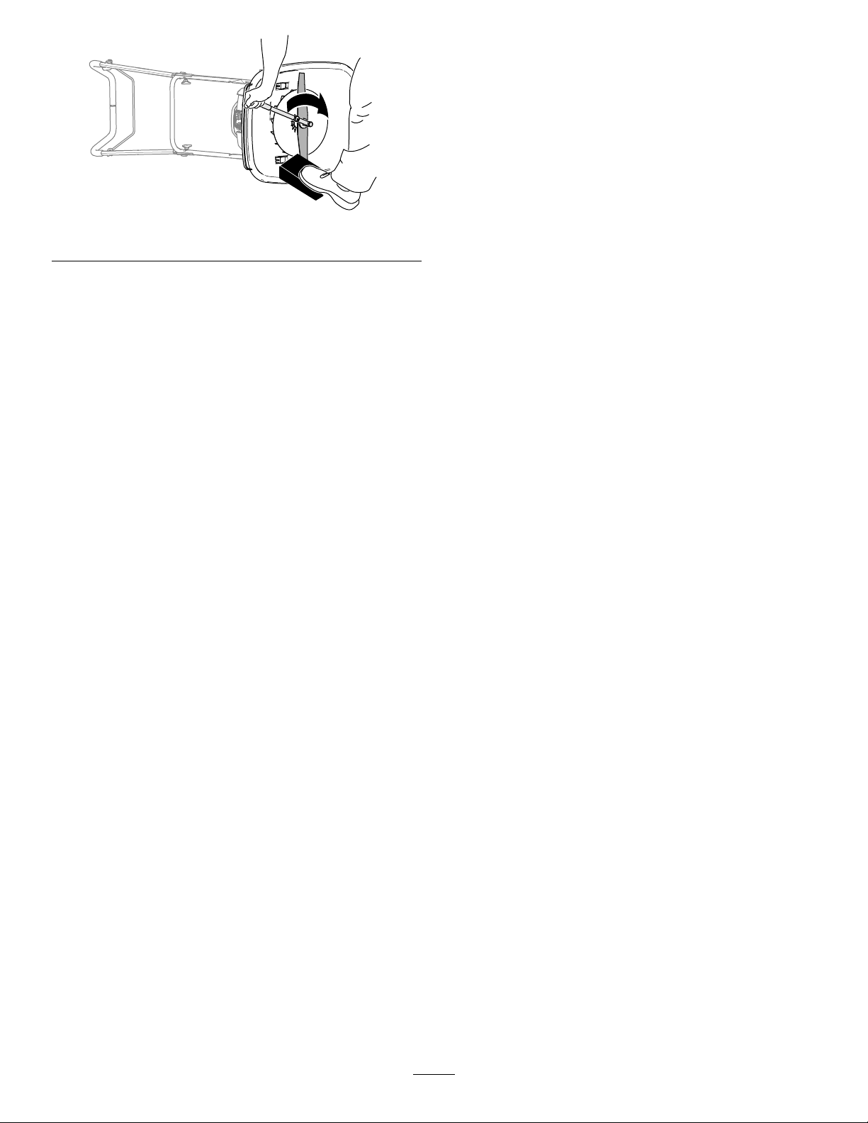
3.KippenSiedieMaschineaufrecht.
g364889
Bild45
25

Einlagerung
Sicherheitbeider
langsamamRücklaufstarterkabel,umdasÖl
imZylinderzuverteilen.
6.SetzenSiedieZündkerzewiedereinundziehen
SiedieseaufeinDrehmomentvon20N∙man.
Einlagerung
•StellenSievordemVerlassendesFahrersitzes
denMotorab,ziehenSiedenSchlüsselab(sofern
vorhanden)undwartenSie,bisallebeweglichen
TeilezumStillstandgekommensind.LassenSie
dieMaschineabkühlen,bevorSiesieeinstellen,
warten,reinigen,odereinlagern.
•LassenSiedenMotorabkühlen,bevorSie
dieMaschineineinemgeschlossenenRaum
abstellen.
•LassenSiedenMotorabkühlen,bevorSie
dieMaschineineinemgeschlossenenRaum
abstellen.
•LagernSiedieMaschineoderdenBenzinkanister
nieanOrtenmitoffenerFlamme,Funkenoder
Zündamme,z.B.Warmwasserbereiter,oder
andereGeräte.
•EntfernenSieGras,BlätterundSchmutzansamm-
lungenausdemAuspuffunddemMotorraum,um
Brändezuvermeiden.
VorbereitenderMaschine
7.PrüfenSiedasMesserregelmäßigauf
AbnutzungundDefekte.WenndasMesser
stumpfist,lassenSiesieschärfen;wenndas
Messerbeschädigtist,ersetzenSiees.
8.ZiehenSiealleSchraubenundMutternan.
9.LagernSiedieMaschineaneinemkühlen,
sauberenundtrockenenOrtein.
fürdieEinlagerung
WARNUNG:
Kraftstoffdämpfekönnenexplodieren.
•LagernSieKraftstoffnichtlängerals
30Tage.
•LagernSiedieMaschinenichtin
geschlossenenRäumeninderNähevon
offenemFeuerein.
•LassenSievordemEinlagerndenMotor
abkühlen.
1.FüllenSiebeimletztenBetankenfürdasJahr
demfrischenBenzineinenKraftstoffstabilisator
zu.FolgenSiedabeidenAnweisungendes
Motorherstellers.
2.LassenSiedieMaschinesolangelaufen,bis
derMotorinfolgevonBenzinknappheitabstellt.
3.StartenSiedenMotorundlassenSieihnlaufen,
biserabstellt.WennSiedenMotornichtmehr
startenkönnen,istdasKraftstoffsystemleer.
4.SchließenSiedenZündkerzensteckerab.
5.EntfernenSiedieZündkerze,füllenSie30ml
ÖlindieÖffnungeinundziehenSiemehrmals
26

Fehlersucheund-behebung
Problem
DerMotorsolltenichtanspringen.
DerMotorspringtnurschweranoder
verliertanLeistung.
MöglicheUrsacheBehebungsmaßnahme
1.DerZündkerzensteckeristnichtauf
derZündkerze.
2.DasEntlüftungslochimTankdeckelist
verstopft.
3.DieZündkerzeweistEinkerbungen
auf,istverschmutztoderhatden
falschenElektrodenabstand.
4.DerKraftstofftankistleer,oderdie
KraftstoffanlageenthältaltenKraftstoff.
1.DasEntlüftungslochimTankdeckelist
verstopft.
2.DasLuftlterelementistverschmutzt
undbehindertdieLuftströmung.
3.DieUnterseitedesMaschinengehäusesweistSchnittgutrückständeund
Schmutzauf.
4.DieZündkerzeweistEinkerbungen
auf,istverschmutztoderhatden
falschenElektrodenabstand.
5.DerMotorölstandistzuniedrigbzw.zu
hochoderdasÖliststarkverschmutzt.
6.DerKraftstofftankenthältalten
Kraftstoff.
1.SchließenSiedenZündkerzenstecker
wiederandieZündkerzean.
2.ReinigenSiedasEntlüftungslochim
TankdeckeloderwechselnSieihnaus.
3.PrüfenSiedieZündkerzeundstellen
SiebeiBedarfdenElektrodenabstand
ein.ErsetzenSiedieZündkerze,
wenndieseEinkerbungenaufweist,
verschmutztodergerissenist.
4.EntleerenSiedenKraftstofftank
und/oderfüllenihnmitfrischem
Benzinauf.WennSiedasProblem
nichtbeseitigenkönnen,wendenSie
sichbitteanIhrenofziellenToro
Vertragshändlerodereineautorisierte
Vertragswerkstatt.
1.ReinigenSiedasEntlüftungslochim
TankdeckeloderwechselnSieihnaus.
2.ReinigenSiedenVorlterund/oder
tauschendenPapierlterim
Luftltergehäuseaus.
3.ReinigenSiedieUnterseitedes
Maschinengehäuses.
4.PrüfenSiedieZündkerzeundstellen
SiebeiBedarfdenElektrodenabstand
ein.ErsetzenSiedieZündkerze,
wenndieseEinkerbungenaufweist,
verschmutztodergerissenist.
5.PrüfenSiedasMotoröl.WechselnSie
dasÖl,wennesverschmutztist,füllen
SieÖlaufoderlassenesab,bisder
ÖlstandandieFüllmarkeamPeilstab
liegt.
6.EntleerenSiedenKraftstofftankund
füllenihnmitfrischemBenzinauf.
DerMotorläuftnichtrund.
DieMaschineoderderMotorvibriertstark.
1.DerZündkerzensteckeristnichtauf
derZündkerze.
2.DieZündkerzeweistEinkerbungen
auf,istverschmutztoderhatden
falschenElektrodenabstand.
3.DerLuftltereinsatzistverschmutzt
undbehindertdieLuftströmung.
1.DieUnterseitedesMaschinengehäusesweistSchnittgutrückständeund
Schmutzauf.
2.DieMotorbefestigungsschraubensind
locker.
3.
DieSchraubeanderSchneideinheit
istlocker.
27
1.SchließenSiedenZündkerzenstecker
wiederandieZündkerzean.
2.PrüfenSiedieZündkerzeundstellen
SiebeiBedarfdenElektrodenabstand
ein.ErsetzenSiedieZündkerze,
wenndieseEinkerbungenaufweist,
verschmutztodergerissenist.
3.ReinigenSiedenVorlterund/oder
tauschendenPapierlterim
Luftltergehäuseaus.
1.ReinigenSiedieUnterseitedes
Maschinengehäuses.
2.ZiehenSiedieMotorbefestigungsschraubenan.
3.
ZiehenSiedieSchraubeander
Schneideinheit.

Problem
MöglicheUrsacheBehebungsmaßnahme
1.Siemähenwiederholtimgleichen
Muster.
2.DieUnterseitedesMaschinengehäusesweistSchnittgutrückständeund
Schmutzauf.
1.VariierenSieIhrMähmuster. DasSchnittmusteristnichtgleichmäßig.
2.ReinigenSiedieUnterseitedes
Maschinengehäuses.
28

EEA/UKDatenschutzerklärung
TorosVerwendungIhrerpersönlichenInformationen
TheToroCompany(„T oro“)respektiertIhrePrivatsphäre.WennSieunsereProduktekaufen,könnenwirbestimmtepersönlicheInformationenüber
Siesammeln,entwederdirektvonIhnenoderüberIhrelokaleToro-NiederlassungoderIhrenHändler.T oroverwendetdieseInformationen,um
vertraglicheVerpichtungenzuerfüllen–z.B.umIhreGarantiezuregistrieren,IhrenGarantieanspruchzubearbeitenoderSieimFalleeinesRückrufs
zukontaktieren–undfürlegitimeGeschäftszwecke–z.B.umdieKundenzufriedenheitzumessen,unsereProduktezuverbessernoderIhnen
ProduktinformationenzurVerfügungzustellen,diefürSievonInteresseseinkönnten.TorokanndieInformationenimRahmendieserAktivitätenan
ToroTochtergesellschaften,HändleroderGeschäftspartnerweitergeben.WirkönnenauchpersönlicheDatenoffenlegen,wenndiesgesetzlich
vorgeschriebenistoderimZusammenhangmitdemVerkauf,KaufoderderFusioneinesUnternehmens.ToroverkauftIhrepersönlichenInformationen
niemalsananderenUnternehmen.
SpeicherungIhrerpersönlichenDaten
TorowirdIhrepersönlichenDatensolangeaufbewahren,wieesfürdieobengenanntenZweckerelevantistundinÜbereinstimmungmitden
gesetzlichenBestimmungen.FürweitereInformationenüberdiegeltendenAufbewahrungsfristenwendenSiesichbitteanlegal@toro.com.
TorosEngagementfürSicherheit
IhrepersönlichenDatenkönnenindenUSAodereinemanderenLandverarbeitetwerden,indemmöglicherweisewenigerstrengeDatenschutzgesetze
geltenalsinIhremWohnsitzland.WannimmerwirIhreDatenaußerhalbIhresWohnsitzlandesübermitteln,werdenwirdiegesetzlichvorgeschriebenen
Schritteunternehmen,umsicherzustellen,dassangemesseneSicherheitsvorkehrungenzumSchutzIhrerDatengetroffenwerdenundum
sicherzustellen,dassdiesesicherbehandeltwerden.
ZugangundKorrektur
SiehabendasRecht,IhrepersönlichenDatenzukorrigierenundzuüberprüfenoderderVerarbeitungIhrerDatenzuwidersprechenbzw.diese
einzuschränken.BittekontaktierenSieunsdazuperE-Mailunterlegal@toro.com.WennSieBedenkenhaben,wieToromitIhrenDatenumgegangenist,
bittenwirSie,diesdirektmitunszubesprechen.BittebeachtenSie,dasseuropäischeBürgerdasRechthaben,sichbeiIhrerDatenschutzbehörde
zubeschweren.
374-0282RevC

DieGarantievonToro
BeschränkteGarantieüberzweiJahreoder1.500Betriebsstunden
BedingungenundabgedeckteProdukte
TheT oroCompanygewährleistengemäßeinesgegenseitigen
Abkommens,dassdasgewerblicheProduktvonToro(„Produkt“)für
zweiJahreoder1.500Betriebsstunden*(jenachdem,waszuerst
eintritt)freivonMaterial-undVerarbeitungsschädenist.DieseGarantie
giltfüralleProdukte,ausgenommensindAerizierer(dieseProdukte
habeneigeneGarantiebedingungen).BeieinemGarantieanspruch
wirddasProduktkostenlosrepariert,einschließlichDiagnose,
Lohnkosten,ErsatzteilenundTransport.DieGarantiebeginntandem
Termin,andemdasProduktzumOriginalkundenausgeliefertwird.
*MitBetriebsstundenzählerausgestatteteProdukte.
AnweisungenfürdieInanspruchnahmevon
WartungsarbeitenunterGarantie
SiemüssendenofziellenDistributoroderVertragshändlerfürgewerbliche
Produkte,vondemSiedasProduktgekaufthaben,umgehendinformieren,
dassSieeinenGarantieansprucherheben.SolltenSieHilfebeimErmitteln
einesofziellenDistributorsoderVertragshändlerfürgewerblicheProdukte
benötigenoderFragenzudenGarantieansprüchenund-verpichtungen
haben,könnenSieunsunterfolgenderAdressekontaktieren:
ToroCommercialProductsServiceDepartment
811 1LyndaleAvenueSouth
Bloomington,MN55420-1196
+1-952-888-8801oder+1-800-952-2740
E-Mail:commercial.warranty@toro.com
VerantwortungdesEigentümers
AlsProdukteigentümersindSiefürdieerforderlichenWartungsarbeiten
undEinstellungenverantwortlich,dieinderBedienungsanleitungangeführt
sind.ReparaturenvonDefektenamProdukt,diedurchunterlassene
erforderlicheWartungundEinstellungenaufgetretensind,werdenvon
dieserGarantienichtabgedeckt.
NichtvonderGarantieabgedecktePunkteund
Bedingungen
NichtalleProduktfehleroderFehlfunktionen,dieimGarantiezeitraum
auftreten,stellenVerarbeitungs-oderMaterialfehlerdar.DieseGarantie
schließtFolgendesaus:
•ProduktversagenaufgrundderV erwendungvonErsatzteilen,diekeine
ToroOriginalteilesind,oderaufgrundderInstallationoderVerwendung
vonAnbaugeräten,ModikationenodernichtgenehmigtemZubehör.
•Produktfehler,dieaufgrundnichtausgeführterWartungs-und/oder
Einstellungsarbeitenentstehen.
•Produktfehler,dieaufdenmissbräuchlichen,fahrlässigenoder
waghalsigenEinsatzdesProduktszurückzuführensind.
•DurchVerwendungverbrauchteT eile,dienichtdefektsind.Beispiele
vonTeilen,diesichbeimnormalenProdukteinsatzabnutzenoder
verbrauchtwerden,sindu.a.BremsbelägeundBremsbacken,
Kupplungsbeläge,Messer,Spindeln,RollenundLager(abgedichtet
oderschmierbar),Untermesser,Zündkerzen,LaufräderundLager,
Reifen,Filter,RiemenundbestimmteSprühfahrzeugkomponenten,
wiez.B.Membrane,Düsen,DurchussmesserundSicherheitsventile.
•DurchEinwirkungvonaußenaufgetreteneDefektewieunteranderem
Witterung,Lagerungsmethoden,Verunreinigung,Verwendung
ungeeigneterKraftstoffe,Kühlmittel,Schmiermittel,Zusätze,Dünger,
Wasser,oderChemikalien.
•DefekteoderLeistungsproblemeaufgrundvonKraftstoffen(z.B.
Benzin,DieseloderBiodiesel),dienichtdenBranchennormen
entsprechen.
•NormalesGeräuschniveau,normaleVibrationundAbnutzungund
normalerVerschleiß.NormaleVerbrauchsgütersindu.a.Schäden
amSitzaufgrundvonAbnutzungoderAbrieb,abgenutzte,lackierte
Oberächen,verkratzteAufkleberoderFenster.
Teile
Teile,diealsvorgeschriebeneWartungsarbeitenausgewechseltwerden
müssen,werdenfürdenZeitraumbiszurgeplantenAuswechslungdesT eils
garantiert.Teile,dieimRahmendieserGarantieausgewechseltwerden,
sindfürdieLängederOriginalproduktgarantieabgedecktundwerden
dasEigentumvonToro.EsbleibtToroüberlassen,obeinTeilrepariert
oderausgewechseltwird.TorokannüberholteTeilefürReparaturenunter
Garantieverwenden.
GarantiefürDeep-CycleundLithium-Ionen-Akkus
Deep-Cycle-undLithium-Ionen-AkkushabeeinebestimmteGesamtzahl
anKilowatt-Stunden,diesiebereitstellenkönnen.Einsatz-,Auade-und
WartungsverfahrenkönnendieNutzungsdauerdesAkkusverlängernoder
verkürzen.WährendderNutzungdesAkkusindiesemProduktnimmtdie
nützlicheArbeitzwischenAuadeintervallenlangsamab,bisdieAkkus
ganzaufgebrauchtsind.FürdasAuswechselnaufgebrauchterAkkus
(aufgrundnormalerNutzung)istderProdukteigentümerverantwortlich.
Hinweis:(NurLithium-Ionen-Akku):WeitereInformationenndenSiein
derAkkugarantie.
LebenslangeGarantieaufdieKurbelwelle(nurModell
ProStripe02657)
DerProStripe,dermiteinerechtenT oro-Kupplungsscheibeundeiner
verdrehsicherenMesserbremskupplung(integrierteMesserbremskupplung
(BBC)+Kupplungsscheibenbaugruppe)alsErstausrüstungausgestattet
istundvomErstkäufergemäßdenempfohlenenBetriebs-und
Wartungsverfahrenverwendetwird,unterliegteinerlebenslangen
GarantiegegenVerbiegenderMotorkurbelwelle.Maschinen,diemit
Kupplungsscheiben,Messerbremskupplungseinheiten(BBC)undanderen
Vorrichtungenausgestattetsind,fallennichtunterdielebenslangeGarantie
derKurbelwelle.
FürdieKostenvonWartungsarbeitenkommtder
Eigentümerauf
Motoreinstellung,Schmierung,ReinigungundPolieren,Austauschvon
Filtern,KühlmittelunddieDurchführungderempfohlenenWartungsarbeiten
sindeinigedernormalenArbeiten,diederEigentümeraufeigeneKosten
andenToroProduktendurchführenmuss.
AllgemeineBedingungen
ImRahmendieserGarantiehabenSienurAnspruchaufeineReparatur
durcheinenofziellenT oroDistributoroderHändler.
TheToroCompanyhaftetnichtfürmittelbare,beiläugeoder
Folgeschäden,dieausderVerwendungderToroProdukte
entstehen,dievondieserGarantieabgedecktwerden,einschließlich
allerKostenoderAufwendungenfürdasBereitstellenvon
ErsatzgerätenoderServiceinangemessenenZeiträumen,des
AusfallsoderderNichtverwendung,biszumAbschlussderunter
dieserGarantieausgeführtenReparaturarbeiten.Außerden
Emissionsgewährleistungen,aufdieimAnschlussverwiesenwird
(fallszutreffend)bestehtkeineausdrücklicheGewährleistung.Alle
abgeleitetenGewährleistungenzurVerkäuichkeitundEignungfür
einenbestimmtenZwecksindaufdieDauerderausdrücklichen
Gewährleistungbeschränkt.
EinigeStaatenlassenAusschlüssevonbeiläugenoderFolgeschäden
nichtzu;oderschränkendieDauerderabgeleitetenGewährleistungein.
DieobigenAusschlüsseundBeschränkungentreffendaherggf.nichtauf
Siezu.DieseGarantiegibtIhnenbestimmtelegaleRechte;Siekönnen
weitereRechtehaben,diesichvonStaatzuStaatunterscheiden.
HinweisbezüglichderGarantieaufdie
Emissionskontrolle
DasEmissionskontrollsystemdesProduktskannvoneiner
separatenGarantieabgedecktsein,diedieAnforderungenderEPA
(amerikanischeUmweltschutzbehörde)und/oderCARB(CaliforniaAir
ResourcesBoard)erfüllen.DieobenangeführtenBeschränkungen
hinsichtlichderBetriebsstundengeltennichtfürdieGarantieaufdas
Emissionskontrollsystem.SiehedieAngabezurGarantiehinsichtlich
derMotoremissionskontrolleinderBedienungsanleitungoderinden
UnterlagendesMotorherstellers.
374-0253RevI

LänderaußerUSAoderKanada
Kunden,dieProduktevonT orokaufen,dievondenUSAoderKanadaexportiertwurden,solltensichandenToroDistributor(Händler)wenden,um
GarantiepolicenfürdasentsprechendeLandoderdieRegionzuerhalten.SolltenSieausirgendeinemGrundnichtmitdemServicedesHändlers
zufriedenseinoderSchwierigkeitenbeimErhaltderGarantieinformationenhaben,wendenSiesichandenIhrofziellesToroServiceCenter.
374-0253RevI

FormNo.3448-542RevA
MáquinaHoverPro
Nºdemodelo02617—Nºdeserie400000000ysuperiores
®
550
Registresuproductoenwww.T oro.com.
Traduccióndeloriginal(ES)
*3448-542*

Esteproductocumpletodaslasdirectivaseuropeas
aplicables.Sideseamásdetalles,consulte
laDeclaracióndeConformidad(Declarationof
Conformity–DOC)decadaproducto.
Parbrutooneto:Elparbrutoonetodeestemotor
fuecalculadaporelfabricantedelmotorconarreglo
aloestipuladoeneldocumentoJ1940oJ2723de
laSocietyofAutomotiveEngineers(Sociedadde
IngenierosdelAutomóvil–SAE).Debidoaqueel
motorestáconguradoparacumplirlosrequisitosde
seguridad,emisionesyoperación,supotenciarealen
estetipodesegadoraserásignicativamentemenor.
Consultelainformacióndelfabricantedelmotor
incluidaconlamáquina.
g364631
Figura1
Introducción
Estámáquinasehadiseñadoparaquelausen
operarioscomercialescontratadosyusuarios
domésticosparaelmantenimientodelcéspeden
pendientes,ondulacionespronunciadas,áreascerca
delaguaoenelbordedebúnkers.Elusodeeste
productoparaotrospropósitosquelosprevistos
podríaserpeligrosoparaustedyparaotraspersonas.
Leaestemanualdetenidamenteparaaprendera
utilizarymantenercorrectamentesuproducto,y
paraevitarlesionesydañosalproducto.Ustedesel
responsabledeoperarelproductodeformacorrecta
ysegura.
Visitewww.toro.com/en-GBparaobtenermás
información,incluidosconsejosdeseguridad,
materialesdeformación,informaciónsobre
accesorios,ayudaparaencontraraundistribuidoro
pararegistrarsuproducto.
Cuandonecesiteasistenciatécnica,piezasgenuinas
Torooinformaciónadicional,póngaseencontacto
conunServicioTécnicoAutorizadooconAsistencia
alClientedeT oro,ytengaamanolosnúmerosde
modeloyseriedesuproducto.Figura1identicala
ubicaciónenelproductodelosnúmerosdemodeloy
deserie.Escribalosnúmerosenelespacioprovisto.
Importante:Consudispositivomóvil,puede
escanearelcódigoQRdelapegatinadelnúmero
deserie(ensucaso)paraaccederainformación
sobrelagarantía,laspiezas,yotrainformación
sobreelproducto.
1.Ubicacióndelosnúmerosdemodeloydeserie
Anoteacontinuaciónlosnúmerosdemodeloyde
seriedesuproducto:
Nºdemodelo
Nºdeserie
Estemanualidenticapeligrospotencialesycontiene
mensajesdeseguridadidenticadosporelsímbolo
dealertadeseguridad(Figura2),queseñalaun
peligroquepuedecausarlesionesgravesolamuerte
siustednosiguelasprecaucionesrecomendadas.
g000502
Figura2
Símbolodealertadeseguridad
Estemanualutiliza2palabraspararesaltar
información.Importantellamalaatenciónsobre
informaciónmecánicaespecial,yNotaresalta
informacióngeneralquemereceunaatención
especial.
©2021—TheToro®Company
8111LyndaleAvenueSouth
Bloomington,MN55420
Póngaseencontactoconnosotrosenwww.Toro.com.
2
ImpresoenelReinoUnido
Reservadostodoslosderechos

Contenido
Seguridad
Seguridad.................................................................3
Seguridadengeneral.........................................3
Pegatinasdeseguridadeinstrucciones.............4
Montaje.....................................................................6
1Instalacióndelaplacadeajustedel
manillar...........................................................6
2Instalacióndelmanillar....................................6
3Añadidodeaceitealmotor...............................9
Elproducto..............................................................10
Controles..........................................................11
Especicaciones...............................................11
Aperos/accesorios.............................................11
Antesdelfuncionamiento....................................12
Seguridadantesdeluso...................................12
Especicacióndelcombustible.........................12
Llenadodeldepósitodecombustible................12
Vericacióndelniveldeaceitedel
motor.............................................................13
Duranteelfuncionamiento...................................13
Seguridadduranteeluso..................................13
Válvuladecierredelcombustible......................14
Arranquedelmotor...........................................14
Apagadodelmotor...........................................15
Sujecióndelmanillarconlaplacade
ajuste............................................................15
Ajustedelaalturadecorte................................16
Consejosdeoperación....................................17
Despuésdelfuncionamiento...............................18
Seguridaddespuésdeluso..............................18
Mantenimiento........................................................20
Calendariorecomendadodemanteni-
miento..........................................................20
Seguridadenelmantenimiento........................20
Preparaciónparaelmantenimiento..................21
Cambiodellimpiadordeaire.............................21
Especicacióndelaceitedelmotor...................22
Comprobacióndelniveldeaceitedel
motor.............................................................22
Cambiodelaceitedelmotor..............................22
Mantenimientodelabujía.................................23
Mantenimientodelacuchilla.............................24
Almacenamiento.....................................................26
Seguridadduranteelalmacenamiento.............26
Preparacióndelamáquinaparael
almacenamiento...........................................26
Solucióndeproblemas...........................................28
Estamáquinahasidodiseñadaconarregloalo
estipuladoenlanormaENISO5395.
Seguridadengeneral
Importante:Leadetenidamentelasinstrucciones
antesdeusarlamáquinayconsérvelaspara
futurasreferencias.
Esteproductoescapazdeamputarmanosypies
ydelanzarobjetosalaire.Sigasiempretodas
lasinstruccionesdeseguridadconelndeevitar
lesionespersonalesgraves.
•Leaycomprendaelcontenidodeestemanualdel
operadorantesdearrancarelmotor.
•Nopongalasmanosolospiescercadelos
componentesmóvilesdelamáquina.
•Noutilicelamáquinasinoestáncolocadosysino
funcionancorrectamentetodoslosprotectoresy
dispositivosdeseguridad.
•Mantengaaotraspersonas,especialmentea
losniños,alejadasdeláreadeoperación.No
permitaqueestevehículoseautilizadoporniños.
Sólopermitaquemanejenlamáquinapersonas
responsables,formadas,familiarizadasconlas
instruccionesyfísicamentecapacesdeutilizar
lamáquina.Lanormativalocalpuedeimponer
límitessobrelaedaddeloperador.
•Apagueelmotor,retirelallave(ensucaso)
yespereaquesedetengatodomovimiento
antesdeabandonarelpuestodeloperador.
Dejequeseenfríelamáquinaantesdehacer
trabajosdeajuste,mantenimiento,limpiezao
almacenamiento.
Elusoomantenimientoincorrectodeestamáquina
puedecausarlesiones.Parareducirelpeligrode
lesiones,sigaestasinstruccionesdeseguridady
presteatenciónsiemprealsímbolodealertade
seguridad
Peligro–instrucciónrelativaalaseguridadpersonal.
Elincumplimientodeestasinstruccionespuededar
lugaralesionespersonalesolamuerte.
,quesignica:Cuidado,Advertenciao
3

Pegatinasdeseguridadeinstrucciones
Laspegatinaseinstruccionesdeseguridadestánalavistadeloperadoryestánubicadas
cercadecualquierzonadepeligropotencial.Sustituyacualquierpegatinaqueestédañadao
quefalte.
1.Paradadelmotor
decalh295159
H295159
1.Peligrode
corte/desmembramiento
demanoopie;unidad
decorte–mantenga
lasmanosylospies
alejadosdelaspiezasen
movimiento.
decal11 1-9826
111-9826
2.Leaelmanualdel
operador.
decal134-7020
134-7020
1.Antesdeinclinarlamáquinapararealizartareasde
mantenimiento,desconectelabujíayleaelManualdel
operador.
4

decal134-7039
134-7039
1.Advertencia–recibaformaciónsobreelproducto;leael
Manualdeloperador.
2.Peligrodecorte/desmembramientodemanosopies,hilode
4.Peligrodeobjetosarrojados–mantengaalejadasaotras
personas.
5.Advertencia–notoquelassuperciescalientes.
nylon;desconecteelcabledelabujíaantesdetrabajarenla
máquina.
3.Advertencia–lleveprotecciónauditivayocular.6.Advertencia–noseacerquealaspiezasenmovimiento;
mantengacolocadostodoslosprotectores.
5

Montaje
1
Instalacióndelaplacade
ajustedelmanillar
Piezasnecesariasenestepaso:
1
Manillarinferior
1Placadeajuste
1
Perno(6x35mm)
3
Arandela(6mm)
1
Contratuerca(6mm)
Procedimiento
1.Determinelaalturadelmanillarcuandolaplaca
deajusteestéjaeneltopedesubida(Figura
3).
2.Alineeeltaladroenlaplacadeajusteconel
taladroenelmanillarinferior(Figura4).
Nota:Solopuedeusarlaplacadeajustepara
sujetarelmanillarenposiciónverticalcuandomonte
elmanillarenlaposiciónbajade103,4cm.
Figura4
1.Manillarinferior4.Arandela(6mm)
2.Placadeajuste
3.Perno(6x35mm)
3.Montelaplacadeajusteenelmanillarconun
perno(6x35mm),3arandelas(6mm)yuna
contratuerca(6mm).
4.Aprietelacontratuercayelperno.
5.Contratuerca(6mm)
Nota:Asegúresedequepuedegirarlaplaca
deajuste.
g364679
Figura3
1.Posiciónbajadelmanillar3.Placadeajuste
2.Topedesubida4.Posiciónaltadelmanillar
g367240
6

2
Instalacióndelmanillar
Piezasnecesariasenestepaso:
4
CasquillosenT
2
Perno(6x55mm)
6
Arandela(6mm)
2
Contratuerca(6mm)
2Pomo
2PernoenU
Acoplamientodelmanillar
1Manillarsuperior
1
Perno(¼"x1¾")
1
Contratuerca(¼")
Montajedelmanillarinferiorenla
máquina
g364680
Figura6
1.Topedesubida2.Placadeajuste
3.Alineeeltaladroenelmanillarconlostaladros
enloscasquillos(Figura7)yjeelmanillarala
máquinaconunperno(6x55mm),2arandelas
(6mm)yunacontratuerca(6mm).
1.Monte5casquillosenTenlasbridasdel
manillardelacarcasadecorte(Figura5).
Figura5
1.CasquillosenT
2.Bridasdelmanillar
(carcasadecorte)
2.Alineelaplacadeajustedelmanillarconeltope
desubidaenlacarcasa(Figura6).
g364682
Figura7
1.Manillarinferior
2.Perno(6x55mm)4.Contratuerca(6mm)
3.Arandela(6mm)
g364681
4.Repitaelpaso3alotroladodelamáquina.
7

Montajedelosmanillaresinferior
ysuperior
1.Alineelostaladrosenelmanillarsuperiorcon
lostaladrosenelmanillarinferior(Figura8).
Figura8
1.Manillarinferior
2.Pomo5.PernoenU
3.Arandela(6mm)
2.Monteelmanillarsuperiorenelmanillarinferior
conlos2pernosenU,2arandelas(6mm)y2
pomos.
4.Manillarsuperior
superioryretirelabarradelamáquina(Figura
10).
g364684
g367353
Figura10
3.Inserteelacoplamientodelcableatravésdel
taladroenelsoportedelabarradepresenciadel
operador,talycomosemuestraenlaFigura1 1.
Montajedelcableparalabarrade
presenciadeloperador
1.Inserteelacoplamientodelextremodela
cubiertadelcableenlatomasuperiordel
acoplamientodelmanillar(Figura9).
Figura9
1.Acoplamientodelmanillar
2.Aprietelapatadelabarradepresenciadel
operadorhastaquepuedaretirarladelmanillar
2.Acoplamiento(cubierta
delcable)
g367355
Figura11
1.Soporte(barrade
presenciadeloperador)
g367356
2.Acoplamientodelcable
4.Inserteelextremodelabarradepresenciadel
operadorenelmanillar,aprieteligeramentela
otrapatadelabarraeinsertelabarraenel
manillar(Figura12).
8

Figura12
5.Fijeelacoplamientodelmanillarenelmanillar
superior(Figura13)conelperno(¼"x1¾")
ylacontratuerca(¼").
3
Añadidodeaceitealmotor
Nosenecesitanpiezas
Procedimiento
g367358
Importante:Susegadorasesuministrasinaceite
enelmotor.Antesdearrancarelmotor,añada
aceitealmotor.
ClasicacióndeservicioAPI:SJosuperior
Viscosidaddelaceite:aceite10W-30
Capacidaddeaceite:0,40litros
1.Llevelamáquinaaunasupercienivelada.
2.Retirelavarilladelcuellodellenadodeaceitey
límpielaconuntrapolimpio(Figura14).
1.Perno(¼"x1¾")
2.Manillarsuperior
g367354
Figura13
3.Acoplamientodelmanillar
4.Contratuerca(¼")
g364715
Figura14
3.Viertalentamenteelaceitedemotor
especicadoenelcuellodellenadodeaceite
(Figura15)yespere3minutos.
9

Figura15
4.Insertelavarillaenelcuellodellenadodeaceite
y,acontinuación,retirelavarilla.
5.Compruebeelniveldeaceiteenlavarilla
(Figura16)
Nota:Sillenademasiadoelmotorconaceite,
vacíeelexceso;consulteCómodrenarelaceite
delmotor(página22).
Elproducto
g364716
g364714
Figura17
Figura16
1.Elniveldeaceiteestáal
máximo.
2.Elniveldeaceitees
demasiadoalto–retire
aceitedelcárter .
3.Elniveldeaceitees
demasiadobajo–añada
aceitealcárter.
6.Sielniveldelaceiteseencuentrapordebajo
dellímitesuperior,limpielavarillaconunpaño
limpioyrepitalospasos3a5hastaqueelnivel
delaceitedelmotorestéenlamarcadellímite
superior.
1.Manillar4.Placadeajustedel
2.Barradepresenciadel
operador
3.Carcasadecorte
g364717
manillar
5.Pomosdelmanillar
g364713
Figura18
1.Agarredelarrancadorde
retroceso
2.Bujía6.Varilla
3.Limpiadordeaire7.Protectordelsilenciador
4.Válvuladecierrede
combustible
5.Tapóndecombustible
7.Insertelavarillaenelcuellodellenadodeaceite
yaprieteamanolavarillaconrmeza.
10

Controles
Especicaciones
g364793
Figura19
1.Barradepresenciadel
operador
2.Válvuladecierrede
combustible
Barradepresenciadeloperador
Labarradepresenciadeloperador(Figura19)
controlaelfrenodelvolanteyelencendidodelmotor.
ModeloAnchuradecorteAnchuradel
producto
0261753cm63,5cm
Aperos/accesorios
Estádisponibleunaseleccióndeaperosyaccesorios
homologadosporT oroquesepuedenutilizarcon
lamáquinaandepotenciaryaumentarsus
prestaciones.PóngaseencontactoconsuServicio
TécnicoAutorizadooconsudistribuidorautorizado
Toro,ovisite://www.T oro.comparaobtenerunalista
detodoslosaperosyaccesorioshomologados.
Paraasegurarunrendimientoóptimoymantener
lacerticacióndeseguridaddelamáquina,utilice
solamentepiezasyaccesoriosgenuinosT oro.Las
piezasderepuestoyaccesoriosdeotrosfabricantes
podríanserpeligrosos,ysuusopodríainvalidarla
garantíadelproducto.
•Aprietelabarrahaciaelmanillarparaponeren
marchaelmotor.
•Sueltelabarradelmanillarparaapagarelmotor.
Válvuladecierredecombustible
Utilicelaválvuladecierredelcombustible(Figura19)
paracontrolarelujodecombustiblealmotor.
•Cierrelaválvuladecierredelcombustibleantes
detransportar,manteneroalmacenarlamáquina.
•Abralaválvuladecierredelcombustiblepara
ponerenmarchaelmotor.
11

Operación
Antesdel
funcionamiento
Seguridadantesdeluso
Seguridadengeneral
•Apagueelmotor,retirelallave(ensucaso)
yespereaquesedetengatodomovimiento
antesdeabandonarelpuestodeloperador.
Dejequeseenfríelamáquinaantesdehacer
trabajosdeajuste,mantenimiento,limpiezao
almacenamiento.
•Familiaríceseconlaoperaciónseguradelequipo,
loscontrolesdeloperadorylasseñalesde
seguridad.
•Compruebequetodoslosprotectoresy
dispositivosdeseguridadestáncolocadosyque
funcionancorrectamente.
•Inspeccionesiemprelamáquinaparaasegurarse
dequelascuchillas,lospernosdelascuchillas
yelconjuntodecortenoestándesgastadoso
dañados.
•Inspeccioneeláreadondesevaautilizarla
máquinayretirecualquierobjetoquepudiera
interferirconelfuncionamientodelamáquinao
quepudieraserarrojadoporlamáquina.
•Alajustarlaalturadecorte,ustedpodríatocarla
cuchillaenmovimiento,loquepodríacausarle
graveslesiones.
•Sustituyaelsilenciadorsipresentafallos.
–Noretireeltapóndecombustibleniañada
combustiblealdepósitosielmotorestá
calienteoenmarcha.
–Sisederramacombustible,nointentearrancar
elmotor.Evitecrearunafuentedeignición
hastaquelosvaporesdelcombustiblese
hayandisipado.
–Almaceneelcombustibleenunrecipiente
homologadoymanténgalofueradelalcance
delosniños.
–Vuelvaacolocarconrmezaeltapónen
eldepósitodecombustibleydetodoslos
envasesdecombustible.
•Elcombustibleesdañinoomortalsiesingerido.
Laexposiciónalargoplazoalosvaporespuede
causarlesionesyenfermedadesgraves.
–Evitelarespiraciónprolongadadelosvapores.
–Mantengalasmanosylacaraalejadasde
laboquillaydelaaberturadeldepósitode
combustible.
–Mantengaalejadoelcombustibledelosojos
ylapiel.
Especicacióndel
combustible
Tipo
Octanajemínimo87(US)o91(RON;fuerade
Etanol
MetanolNinguno
MTBE(étermetiltert-butílico)Menosdel15%porvolumen
AceiteNoañadiralcombustible
Gasolinasinplomo
losEstadosUnidos)
Nomásdel10%porvolumen
Seguridad–Combustible
•Elcombustibleesextremadamenteinamable
yaltamenteexplosivo.Unincendioouna
explosiónprovocadosporelcombustiblepuede
causarlequemadurasaustedyaotraspersonas
asícomodañosmateriales.
–Paraevitarqueunacargaestáticaincendie
elcombustible,coloqueelrecipientey/ola
máquinadirectamentesobreelsueloantesde
repostar,noenunvehículoosobreotroobjeto.
–Añadaodreneeldepósitodecombustibleen
elexterior,enunazonaabiertayconelmotor
frío.Limpiecualquiercombustiblederramado.
–Lleneeldepósitodecombustibleenelexterior,
enunazonaabiertayconelmotorfrío.Limpie
cualquiercombustiblederramado.
–Nomanejecombustiblesiestáfumando,ni
cercadeunallamadesnudaochispas.
Utilicesolamentecombustiblelimpioyfresco(nomás
de30díasdeantigüedad)deorigenacreditado.
Importante:Parareducirlosproblemasde
arranque,añadaestabilizador/acondicionadoral
combustiblefresco,siguiendolasindicaciones
delfabricantedelestabilizador/acondicionadorde
combustible.
Llenadodeldepósitode
combustible
Nota:Consulteelmanualdelpropietariodelmotorsi
deseamásinformación.
1.Limpielazonaalrededordeltapóndeldepósito
decombustibleyretireeltapóndeldepósito.
2.Lleneeldepósitodecombustibleconel
combustibleespecicado,talycomosemuestra
enlaFigura20.
12

Figura20
1.53mm2.Nivelsuperiorde
combustible
3.Coloqueeltapóndeldepósitodecombustible.
Vericacióndelnivelde
aceitedelmotor
ConsulteComprobacióndelniveldeaceitedelmotor
(página22).
•Arranqueelmotorsiguiendolasinstruccionesy
conlospiesbienalejadosdelacuchilla.
•Noinclinelamáquinamásdelonecesariopara
arrancarelmotorylevanteúnicamentelaparte
queestéalejadadeusted.
•Apagueelmotor,retirelallave(ensucaso)
yespereaquesedetengatodomovimiento
antesdeabandonarelpuestodeloperador.
Dejequeseenfríelamáquinaantesdehacer
trabajosdeajuste,mantenimiento,limpiezao
almacenamiento.
•Cuandosueltaelcontroldepresenciadel
operador,elmotordebeapagarseylacuchilla
debedetenerseen3segundosomenos.Si
no,dejedeusarlamáquinainmediatamentey
póngaseencontactoconunServicioTécnico
Autorizado.
•Nopermitaqueentrenotraspersonas,
g364718
especialmenteniñosoanimalesdomésticos,enla
zonadetrabajo.Mantengaalosniñospequeños
alejadosdelazonadetrabajoybajolasupervisión
deunadultoresponsablequenoestéutilizando
lamáquina.Parelamáquinasialguienentraen
lazona.
•Utilicelamáquinaúnicamenteconbuena
visibilidadyencondicionesmeteorológicas
apropiadas.Nouselamáquinasihayriesgode
rayos.
•Lahierbamojadaolashojasmojadaspueden
causarlegraveslesionessiustedresbalaytocala
cuchilla.Siesposible,evitesegarencondiciones
húmedas.
Duranteel
funcionamiento
Seguridadduranteeluso
Seguridadengeneral
•Lleveropaadecuada,incluidaprotecciónocular,
pantalónlargo,calzadoresistenteyantideslizante
yprotecciónauditiva.Sitieneelpelolargo,
recójaselo,ynolleveprendasojoyassueltas.
•Prestetodasuatenciónalutilizarlamáquina.No
realiceningunaactividadquecausedistracciones;
delocontrario,podríanproducirselesioneso
dañosmateriales.
•Noutilicelamáquinasiestáenfermo,cansado,o
bajolainuenciadealcoholodrogas.
•Desengranelacuchillaytodoslosembraguesde
latransmisiónantesdearrancarelmotor.
•Extremelaprecauciónalacercarseaesquinas
ciegas,arbustos,árbolesuotrosobjetosque
puedantaparlelavista.
•Estéalertaaagujeros,surcos,montículos,rocas
uotrosobjetosocultos.Elterrenoirregularpodría
hacerquepierdaelequilibrio.
•Silamáquinagolpeaunobjetooempiezaavibrar,
apagueinmediatamenteelmotor,espereaque
sedetengantodaslaspiezasenmovimientoy
desconecteelcabledelabujíaantesdeexaminar
lamáquinaenbuscadedaños.Hagatodaslas
reparacionesnecesariasantesdevolverautilizar
lamáquina.
•Nolevanteotransportenuncalamáquinaconel
motorenmarcha.
•Sielmotorhaestadoenmarcha,estarácalientey
puedecausarlequemadurasgraves.Manténgase
alejadodelmotorcaliente.
•Losgasesdeescapecontienenmonóxidode
carbono,queresultaletalsiseinhala.Nohaga
13

funcionarelmotordentrodeunediciooenun
lugarcerrado.
•Utiliceúnicamentelosaccesoriosyaperos
aprobadosporT oro.
Seguridadenlaspendientes
•Laspendientessonunadelasprincipalescausas
deaccidentesporpérdidadecontrolypueden
provocarlesionesgravesolamuerte.Usted
esresponsabledelaseguridadcuandotrabaja
enpendientes.Laconduccióndelamáquina
enpendientesrequiereextremarlaprecaución.
Antesdeusarlamáquinaenunapendiente,haga
losiguiente:
–Revisarycomprenderlasinstruccionessobre
elusoenpendientesincluidasenestemanual.
–Evaluarlascondicionesdellugarydeldía
paradeterminarsilapendienteessegura
paraconducirlamáquina.Aplicarsiempre
elsentidocomúnyunbuencriterioalahora
derealizarestavaloración.Loscambiosen
elterreno,comolahumedad,puedenafectar
rápidamentealfuncionamientodelamáquina
enpendientes.
•Miresiempredondepisayagarrermementelas
empuñaduras.Camine,nocorrajamás.
•Sieguedeladoaladoenpendientes,nuncahacia
arribaohaciaabajo.
•Presteespecialatenciónalgirarenterreno
inclinado.
Válvuladecierredel
combustible
Figura21
1.Abierta(válvuladecierre
decombustible)
•Gireelmandodelaválvuladecierredel
combustiblehastalaposiciónhorizontalparaabrir
laválvula.
•Gireelmandodelaválvuladecierredel
combustiblehastalaposiciónverticalparaabrir
laválvula.
2.Cerrada(válvuladecierre
decombustible)
g364758
•Nocorteenpendientespronunciadas.
•Extremelasprecaucionesalirhaciaatrásoaltirar
delamáquinahaciausted.
•Evitesegarelcéspedmojado.Sinopisarme,
puederesbalarycaerse.
•Retireoseñalecualquierobstáculo,comozanjas,
baches,surcos,montículos,rocasuotrospeligros
ocultos.Lahierbaaltapuedeocultarobstáculos.
•Extremelasprecaucionesalsegarcercade
terraplenes,fosasotaludes.
•Alutilizarlamáquina,mantengasiemprelasdos
manosenelmanillar.
•Alcortardesdelapartesuperiordeunapendiente,
sinecesitaunmayoralcance,useunmanillar
ampliadohomologado.
Arranquedelmotor
1.Abralaválvuladecierredelcombustible;
consulteVálvuladecierredelcombustible
(página14).
2.Cierrelabarradepresenciadeloperadorcontra
elmanillar.
14

Figura22
detenerseen3segundosomenos.Sinose
parancorrectamente,dejedeusarlamáquina
inmediatamenteypóngaseencontactoconun
ServicioTécnicoAutorizadooconundistribuidor
autorizadoToro.
g017334
1.Manillar2.Barradepresenciadel
operador
3.Pongaelpiesobrelacarcasaeinclinela
máquinahaciausted(Figura23).
Figura23
4.Mientrassostienelabarradepresenciadel
operador,tiredelagarredelarrancadorde
retroceso.
g017366
Figura24
Sujecióndelmanillarconla
placadeajuste
Manillarmontadoenlaposición
inferior
Nota:Sihamontadoelmanillarenlaposición
g364773
inferiorde103,4cm,utilicelaplacadeajustepara
sujetarelmanillarenposiciónvertical.
Nota:Silamáquinanoarrancadespuésde
variosintentos,póngaseencontactoconun
ServicioTécnicoAutorizadooconundistribuidor
autorizadoToro.
Apagadodelmotor
Intervalodemantenimiento:Cadavezqueseutilice
odiariamente
Paraapagarelmotor,sueltelabarradepresencia
deloperador(Figura24).
Importante:Cuandosueltalabarradepresencia
deloperador,elmotoryeldiscodecortedeben
Figura25
1.Placadeajustegirada
haciadelante
2.Placadeajustegirada
haciaatrás
•Paraliberarelmanillar,levanteelmanillarygirela
placadeajustehaciadelante(Figura25)
•Parasujetarelmanillar,coloqueelmanillarygire
laplacadeajustehaciaatrás.
15
g367257

Ajustedelaalturadecorte
ADVERTENCIA
Alajustarlaalturadecorte,ustedpodría
tocarlacuchillaenmovimiento,loquepodría
causarlegraveslesiones.
•Apagueelmotoryespereaquese
detengantodaslaspiezasenmovimiento.
•Lleveguantesresistentesalcorteal
manejarlacuchilla.
CUIDADO
Sielmotorhaestadoenmarcha,el
silenciadorestarámuycalienteypuede
causarlequemadurasgraves.
Manténgasealejadodelsilenciadorsiéste
estácaliente.
Cómoretirarlacuchilla
1.Cierrelaválvuladecierredelcombustible;
consulteVálvuladecierredecombustible
(página11).
2.Desconecteelcabledelabujía.
3.Coloquelamáquinadelado,conlavarillade
aceitehaciaabajo.
g364888
Figura27
5.Utilicelallavesuministradaconlamáquinapara
retirarlacuchilla,girandoelpernoensentido
antihorario(Figura27).
Importante:Llevegafasdeseguridady
guantesresistentesalcortealretirarla
cuchilla.
Colocacióndelosespaciadores
delacuchilla
Cambielaposicióndelosespaciadoresparaajustarla
alturadecorte,talycomosemuestraenlaFigura28.
Nota:Cadaespaciadorcambialaalturadecortede
lacuchilla6,3mm.
Importante:Siemprecoloquelamáquinade
ladoconlavarilladeaceitehaciaabajo.Sila
máquinasecolocaenotraposición,eltren
deválvulaspuedellenarsedeaceite,loque
tardaríaalmenos30minutosendrenarse.
Figura26
4.Utiliceunbloquedemaderaparainmovilizarla
cuchilla(Figura27).
g364990
Figura28
1.Espaciadorcónico4.Retenedor
2.Espaciadores5.Perno
3.Cuchilla
g364720
Instalacióndelacuchilla
1.Alineelosextremoscurvadosdelacuchilla
hacialacarcasadecorteymonteelretenedor,
lacuchilla,losespaciadoresyelespaciador
cónicoenelimpulsorconelperno.
16

Importante:Montesiempreelespaciador
cónicodirectamentedebajodelimpulsoryel
retenedorbajoelcabezaldelperno.
Figura29
1.Impulsor3.Retenedor
2.Espaciadorcónico4.Perno
2.Aprieteelpernodelacuchillaa25N∙m.
Nota:Unpernoapretadoa25N·mquedamuy
rme.Mientrassostienelacuchilladecortecon
unbloquedemadera,apliquetodasufuerzaa
lallavedetorqueyaprieteelperno.
Consejosdeoperación
Consejosgeneralesdesiega
•Coloqueelarodelaplacadeajustebajoeltope
desubidaparaaumentarelmanejodelamáquina.
g364923
g367278
Figura31
•Inspeccionelazonaenlaquevaautilizarla
máquinayretirecualquierobjetoquepudieraser
arrojadoporlamáquina.
•Evitegolpearobjetossólidosconlacuchilla.No
sieguenuncaporencimadeobjetoalguno.
Figura30
3.Inclinelamáquinahaciaarriba,conecteel
cabledelabujíayabralaválvuladecierrede
combustible.
•Silamáquinagolpeaunobjetooempiezaa
vibrar,pareinmediatamenteelmotor,desconecte
elcabledelabujíaeinspeccionelamáquinaen
buscadedaños.
•Paraobtenerelmejorrendimiento,asegúresede
quelacuchillaestáaladaantesdequecomience
latemporadadecorte.
•Sustituyaunacuchilladañadaconunacuchilla
g364889
nuevaderepuestodeToro.
•Asegúresedequelacuchillaaladatengala
mismalongitudqueelhilodecorteintacto.
Siegadelahierba
•Cortesolamenteunterciodelahojadehierba
cadavez.Nocorteconunajusteinferiorala
alturamáxima(30mm)amenosquelahierba
seaescasaoanalesdelotoño,cuandoelritmo
decrecimientodelahierbaempiezaadecaer;
consulteAjustedelaalturadecorte(página16).
•Nosieguehierbademásde15cmdelongitud,
porquelamáquinapuedeatascarseoelmotor
puedecalarse.
•Lahierbamojadaylashojasmojadastiendena
pegarsealsuelo,ypuedenatascarlamáquinao
hacerquesecaleelmotor.Sieguesolamenteen
condicionessecassiesposible.
17

ADVERTENCIA
Lahierbamojadaolashojasmojadas
puedencausarlegraveslesionessiusted
resbalaytocalacuchilla.
Sieguesolamenteencondicionessecas
siesposible.
•Limpielosrecortesdehierbaylosresiduosdela
máquinaparaayudaraprevenirincendios.Limpie
cualquieraceiteocombustiblederramado.
•Noguardenuncalamáquinaounrecipientede
combustiblecercadeunallamadesnuda,chispa
ollamapiloto,porejemploenuncalentadorde
aguauotroelectrodoméstico.
•Estéatentoalposibleriesgodeincendio
encondicionesmuysecas,sigatodaslas
advertenciaslocalesparacasosdeincendio
ymantengalamáquinalibredehierbasecay
residuosdehojas.
•Sielaspectonaldelcéspednoessatisfactorio,
pruebeconunaomásdelastécnicassiguientes:
–Inspeccionelaunidaddecortey/ocambiela
cuchilla.
–Caminarmásdespaciomientrassiega.
–Elevarlaalturadecortedelamáquina.
–Cortarelcéspedconmásfrecuencia.
–Solaparlospasillosdecorteenlugardecortar
unpasillocompletoencadapasada.
Cortedehojas
•Despuésdesegarelcésped,asegúresedequela
mitaddelcéspedseveatravésdelacoberturade
hojascortadas.Esposiblequetengaquehacer
másdeunapasadaporencimadelashojas.
Seguridadduranteeltransporte
•Amarrelamáquina.
•Tengacuidadoalcargaryaldescargarlamáquina.
•Noserecomiendasegarhierbademásde15cm
delargo.Silacoberturadehojasesdemasiado
espesa,puedeatascarlamáquina,haciendoque
secaleelmotor.
•Sieguemásdespaciosilamáquinanocortalas
hojassucientementenas.
Despuésdel
funcionamiento
Seguridaddespuésdeluso
Seguridadengeneral
•Apagueelmotor,retirelallave(ensucaso)
yespereaquesedetengatodomovimiento
antesdeabandonarelpuestodeloperador.
Dejequeseenfríelamáquinaantesdehacer
trabajosdeajuste,mantenimiento,limpiezao
almacenamiento.
18

Limpiezadelamáquina
Intervalodemantenimiento:Despuésdecadauso
ADVERTENCIA
Lamáquinapuedesoltarmaterialdedebajo
delacarcasa.
•Lleveprotecciónocular.
•Permanezcaenlaposicióndeoperación
(detrásdelmanillar).
•Nopermitalapresenciadeotraspersonas
enlazona.
1.Coloquelamáquinadelado,conlavarillade
aceitehaciaabajo.
Importante:Siemprecoloquelamáquinade
ladoconlavarilladeaceitehaciaabajo.Sila
máquinasecolocaenotraposición,eltren
deválvulaspuedellenarsedeaceite,loque
tardaríaalmenos30minutosendrenarse.
2.Utiliceuncepillooairecomprimidoparaeliminar
lahierbaylosresiduosdelprotectordelescape,
lacubiertasuperioryelrestodelacarcasa.
3.Limpieelsistemaderefrigeración;retirelos
recortesdehierba,residuosysuciedadde
lasaletasderefrigeracióndelmotorydel
arrancador.
Nota:Limpieelsistemaderefrigeracióncon
másfrecuenciasihaymuchasuciedadogran
cantidadderecortes.
19

Mantenimiento
Calendariorecomendadodemantenimiento
Intervalodemanteni-
mientoyservicio
Despuésdelasprimeras
5horas
Cadavezqueseutilice
odiariamente
Despuésdecadauso
Cada100horas
Cadaaño
Procedimientodemantenimiento
•Cambiodelaceitedelmotor.
•Asegúresedequeelmotorseapagaen3segundosomenosdespuésdesoltarla
barradepresenciadeloperador.
•Comprobacióndelniveldeaceitedelmotor.
•Inspeccionelacuchillaparaasegurarsedequenoestádesgastadanidañada.Si
lacuchillaestádañada,sustitúyalainmediatamente.
•Limpielosrecortesdehierbaylasuciedaddelamáquinaentera.
•Reviselabujíaycámbieladesernecesario.
•Cambieelltrodeaire;cámbieloconmásfrecuenciaencondicionesdemucho
polvo.
•Cambiodelaceitedelmotor.
•Cambielacuchillaohagaquelaalen(másamenudosisedesalarápidamente).
Seguridadenel
mantenimiento
•Apagueelmotor,retirelallave(ensucaso)
yespereaquesedetengatodomovimiento
antesdeabandonarelpuestodeloperador.
Dejequeseenfríelamáquinaantesdehacer
trabajosdeajuste,mantenimiento,limpiezao
almacenamiento.
•Nocambielosajustesdelreguladordelmotorni
hagafuncionarelmotoraunavelocidadexcesiva.
•Paragarantizarunrendimientoóptimodela
máquina,utiliceúnicamentepiezasderepuesto
yaccesoriosgenuinosdeT oro.Laspiezasde
repuestoyaccesoriosdeotrosfabricantespodrían
serpeligrosos,ysuusopodríainvalidarlagarantía
delproducto.
•Desconecteelcabledelabujíaantesderealizar
cualquierprocedimientodemantenimiento.
•Lleveguantesyprotecciónocularalrealizarel
mantenimientodelamáquina.
•Inspeccionelamáquinaregularmenteysustituya
cualquierpiezaqueestédesgastadaodañada.
Nosustituyalosmediosdecorteconpiezasde
metal;utiliceúnicamenteloselementosdecorte
idóneosparasuusoalavelocidaddeoperación
delamáquina.
•Nomanipulenuncalosdispositivosdeseguridad.
Comprueberegularmentequefuncionan
correctamente.
•Alinclinarlamáquina,puedehaberfugasde
combustible.Elcombustibleesinamabley
explosivo,ypuedecausarlesionespersonales.
Dejefuncionarelmotorhastaquenoquede
combustible,oretirelagasolinaconunabomba
demano;nuncautiliceunsifón.
•Mantengaapretadastodaslasjacionespara
asegurarsedequelamáquinaestáencondiciones
segurasdefuncionamiento.
20

Preparaciónparael
Cambiodellimpiadorde
mantenimiento
ADVERTENCIA
Alinclinarlamáquina,puedehaberfugasde
combustible.Elcombustibleesinamable
yexplosivo,ypuedecausarlesiones
personales.
Dejeelmotorenmarchahastaquenoquede
combustible,oretireelcombustibleconuna
bombademano;nuncautiliceunsifón.
Importante:Siemprecoloquelamáquinadelado
conlavarilladeaceitehaciaabajo.Silamáquina
secolocaconlavarillahaciaarriba,eltrende
válvulaspuedellenarsedeaceite,loquetardaría
almenos30minutosendrenarse.
1.Apagueelmotoryespereaquesedetengan
todaslaspiezasenmovimiento.
2.Llevelamáquinaaunasupercienivelada.
3.Desconecteelcabledelabujía(Figura32).
aire
Intervalodemantenimiento:Cadaaño
1.Presionehaciaabajoloscierresdelaparte
superiordelatapadelltrodeaire(Figura33).
Figura32
4.Cierrelaválvuladecierredelcombustible;
consulteVálvuladecierredelcombustible
(página14).
Importante:Sivaarepararlamáquina,
vacíeeldepósitodecombustible.
5.Despuésderealizarel/losprocedimiento(s)de
mantenimiento,abralaválvuladecombustible
yconecteelcabledelabujía.
g364771
Figura33
1.Cierres(tapadeltrode
aire)
2.Elementodeltro
2.Retirelatapa.
3.Retireelelementodelltro(Figura33).
4.Inspeccioneelltrodeairedepapel.
A.Sielltroestádañado,mojadoconaceite
ocombustibleoexcesivamentesucio,
sustitúyalo.
B.Sielltroestásucio,golpéelovarias
g017342
vecesenunasupercieduraopaseaire
comprimidoamenosde2,07baratravés
delladodelltroqueestáfrentealmotor.
3.Basedelltrodeaire
Nota:Noutiliceuncepilloparalimpiarel
ltro;elcepilladoobligaalasuciedada
penetrarenlasbras.
5.Limpielabasedelltrodeaireylatapacon
unpañohúmedo.Nodejequelasuciedad
penetreenelconductodeaire.
6.Instaleelltroenlabasedelltro.
7.Coloquelatapa.
21

Especicacióndelaceite
delmotor
ClasicacióndeservicioAPI:SJosuperior
Viscosidaddelaceite:aceite10W-30
Comprobacióndelnivelde
aceitedelmotor
Intervalodemantenimiento:Cadavezqueseutilice
odiariamente
1.Preparelamáquinaparaelmantenimiento;
consultePreparaciónparaelmantenimiento
(página21).
2.Retirelavarilladelcuellodellenadodeaceite
ylímpielaconuntrapolimpio.
3.Insertelavarillaenelcuellodellenadodeaceite
y,acontinuación,retirelavarilla.
Importante:Noenrosquelavarillaenel
cuellodellenado.
4.Compruebeelniveldeaceiteenlavarilla.
Figura34
g364716
Figura35
6.Limpielavarillaconunpañolimpioyrepitalos
pasos3a5hastaqueelniveldelaceitedel
motorestéenlamarcadellímitesuperior.
7.Insertelavarillaenelcuellodellenadodeaceite
yaprieteamanolavarillaconrmeza.
Cambiodelaceitedelmotor
Intervalodemantenimiento:Despuésdelas
primeras5horas
Cadaaño
Cómodrenarelaceitedelmotor
1.Sielmotorestáfrío,déjelofuncionarentre1y2
minutosparacalentarelaceite.
2.Asegúresedequeeldepósitodecombustible
nocontienecombustible(oquecontienemuy
poco)cuandocoloquelamáquinadelado.
3.Preparelamáquinaparaelmantenimiento;
consultePreparaciónparaelmantenimiento
(página21).
4.Retirelavarilladelcuellodellenadodeaceite
ylímpielaconuntrapolimpio.
5.Coloqueunrecipientejuntoalacarcasaen
g017332
ellateraldelcuellodellenadodeaceitedela
máquinaysobreelsuelo(Figura35).
1.Elniveldeaceiteestáal
máximo.
2.Elniveldeaceitees
demasiadoalto–retire
aceitedelcárter .
5.Sielniveldeaceiteestácercaopordebajo
delamarcadellímiteinferiorenlavarilla
(Figura34),viertalentamenteelaceitedemotor
especicadoenelcuellodellenadodeaceite
(Figura35)yespere3minutos.
3.Elniveldeaceitees
demasiadobajo–añada
aceitealcárter.
g364772
Figura36
6.Coloquelamáquinadeladoconelcuellode
llenadodeaceitehaciaabajoparadrenarel
aceiteatravésdelcuellodellenado.
22

Importante:Siemprecoloquelamáquinade
ladoconlavarilladeaceitehaciaabajo.Sila
máquinasecolocaenotraposición,eltren
deválvulaspuedellenarsedeaceite,loque
tardaríaalmenos30minutosendrenarse.
7.Pongalamáquinaenlaposiciónnormalde
operación.
8.Limpieelaceitederramadodelamáquina.
Nota:Eliminecorrectamenteelaceiteusadoenun
centrodereciclajehomologado.
Añadidodeaceitealmotor
Capacidaddeaceite:0,40litros
1.Viertalentamenteelaceitedemotor
especicadoenelcuellodellenadodeaceite
(Figura35)yespere3minutos.
Figura37
2.Insertelavarillaenelcuellodellenadodeaceite
y,acontinuación,retirelavarilla.
Importante:Noenrosquelavarillaenel
cuellodellenado.
3.Compruebeelniveldeaceiteenlavarilla
(Figura38)
Nota:Sillenademasiadoelmotorconaceite,
vacíeelexceso;consulteCómodrenarelaceite
delmotor(página22).
g017332
Figura38
1.Elniveldeaceiteestáal
máximo.
2.Elniveldeaceitees
demasiadoalto–retire
aceitedelcárter .
3.Elniveldeaceitees
demasiadobajo–añada
aceitealcárter.
4.Sielniveldelaceiteseencuentrapordebajo
dellímitesuperior,limpielavarillaconunpaño
limpioyrepitalospasos1a3hastaqueelnivel
delaceitedelmotorestéenlamarcadellímite
superior.
5.Insertelavarillaenelcuellodellenadodeaceite
g364716
yaprieteamanolavarillaconrmeza.
Mantenimientodelabujía
Intervalodemantenimiento:Cada100horas
Especicacióndelabujía:ChampionRN9YCo
equivalente.
1.Preparelamáquinaparaelmantenimiento;
consultePreparaciónparaelmantenimiento
(página21).
2.Limpiealrededordelabujía.
3.Retirelabujíadelaculata.
Importante:Silabujíaestádesgastada,
dañadaosucia,cámbiela.Nolimpielos
electrodos,porquecualquierarenillaque
entreenelcilindropuededañarelmotor.
4.Ajusteelespacio(Figura39)entreelelectrodo
centralyellaterala0,76mm.
23
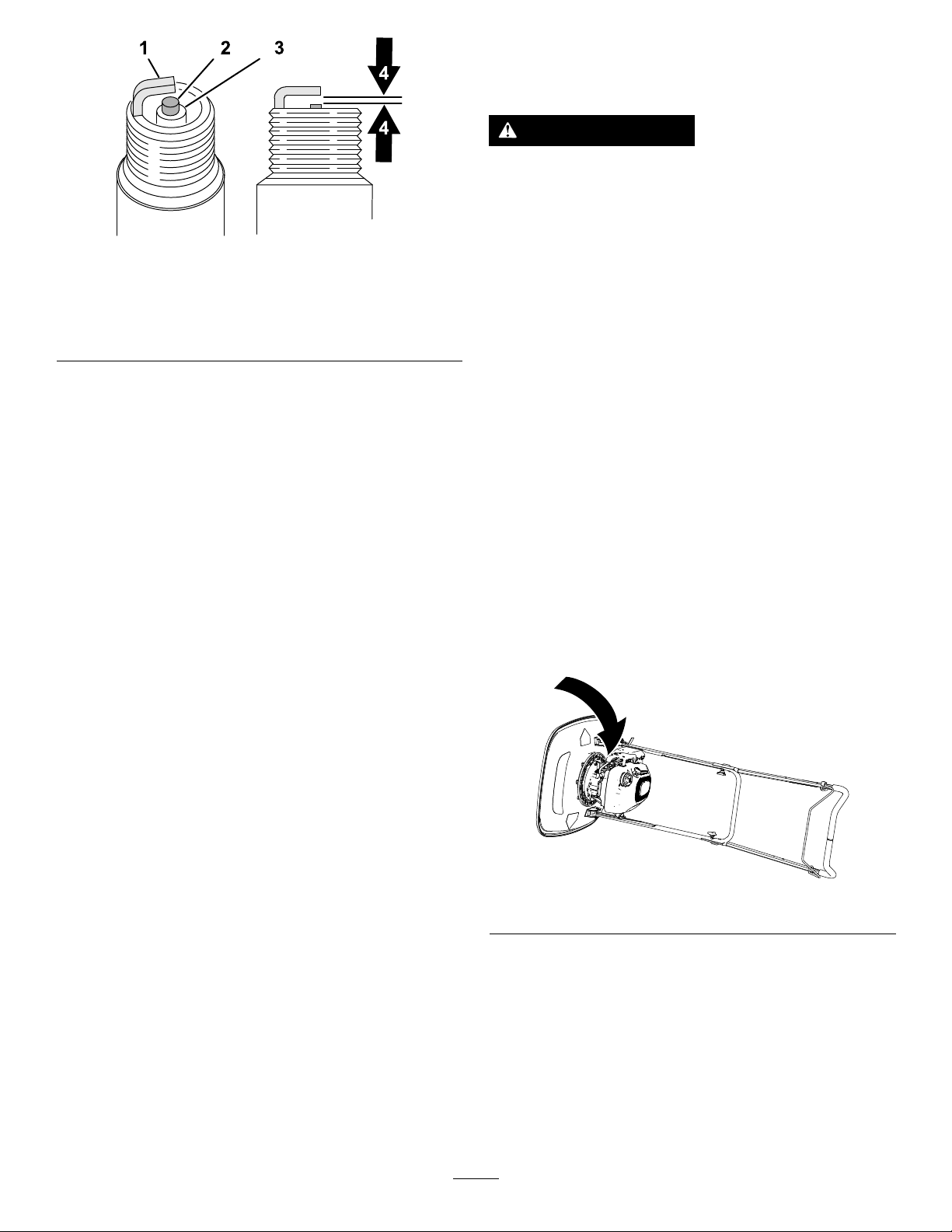
Mantenimientodela
cuchilla
ADVERTENCIA
Lacuchillaestámuyalada;cualquier
contactoconlacuchillapuedecausar
lesionespersonalesgraves.
Figura39
1.Aislantedelelectrodo
central
2.Electrodolateral4.Distanciaentreelectrodos:
5.Instalelabujíaylajunta.
6.Aprietelabujíaa20N·m.
7.Conecteelcabledelabujía.
3.Aislante
0,76mm
g326888
•Desconecteelcabledelabujía.
•Lleveguantesresistentesalcorteal
realizartareasdemantenimientoenla
cuchilla.
Comprobacióndelacuchilla
Intervalodemantenimiento:Cadavezque
seutiliceodiariamenteSila
cuchillaestádañada,sustitúyala
inmediatamente.
1.Preparelamáquinaparaelmantenimiento;
consultePreparaciónparaelmantenimiento
(página21).
2.Coloquelamáquinadeladoconelcuellode
llenadodeaceitehaciaabajo.
Importante:Siemprecoloquelamáquinade
ladoconlavarilladeaceitehaciaabajo.Sila
máquinasecolocaenotraposición,eltren
deválvulaspuedellenarsedeaceite,loque
tardaríaalmenos30minutosendrenarse.
Figura40
3.Inspeccionelacuchillaparaasegurarsedeque
noestádesgastadanidañada.
•Silacuchillaestádañadaoagrietada,
retírelaysustitúyalainmediatamente.
•Sielbordedelacuchillaestáromootiene
mellas,retírela,afílelaosustitúyalaeinstale
lacuchilla.
4.Pongalamáquinadepie.
24
g364720
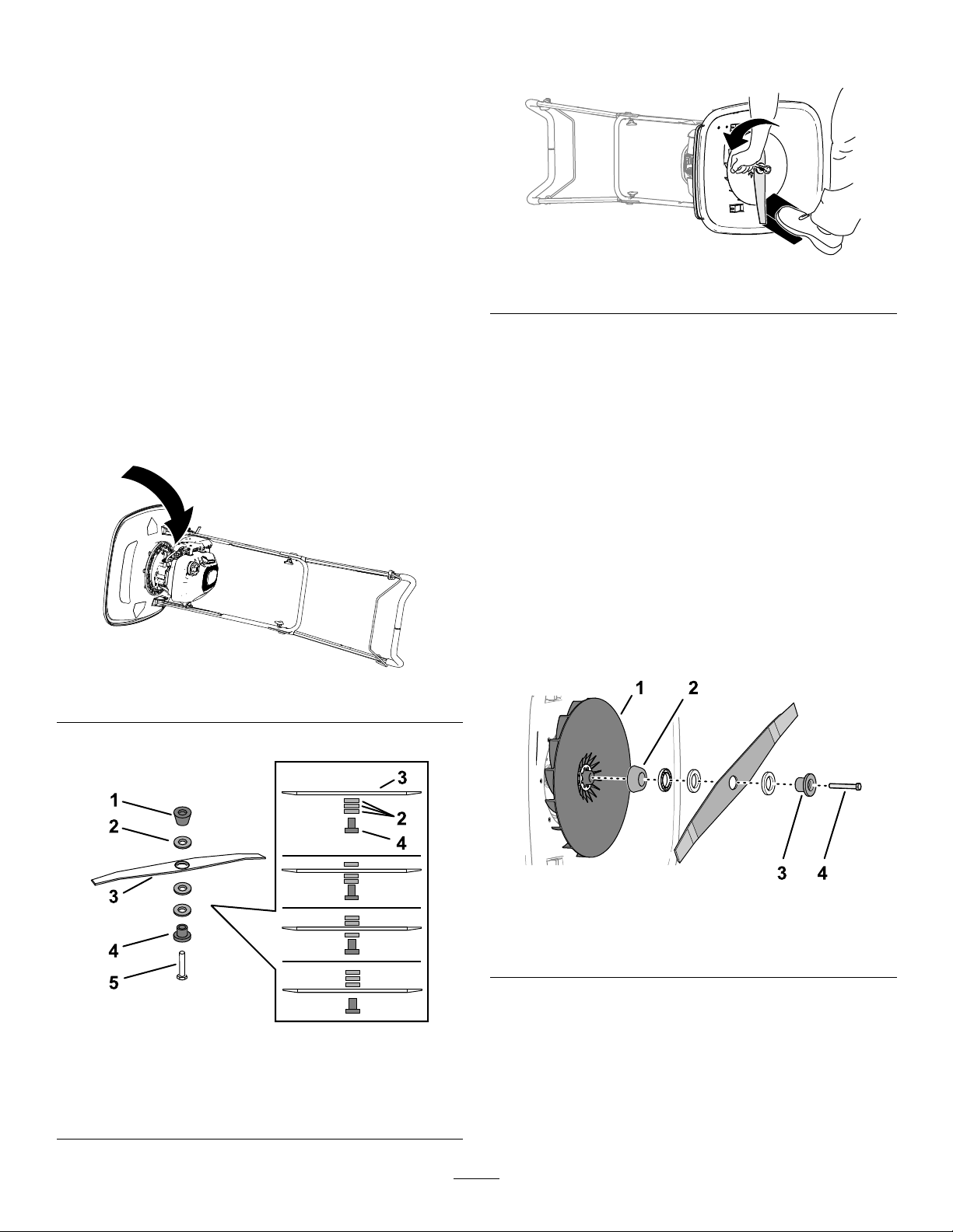
Cambiodelacuchilla
Intervalodemantenimiento:Cadaaño
Importante:Senecesitaunallavedinamométrica
parainstalarlacuchilla.Sinodisponedeuna
llavedinamométricaopreerenorealizareste
procedimiento,póngaseencontactoconun
ServicioTécnicoAutorizadooconundistribuidor
autorizadoToro.
Cómoretirarlacuchilla
1.Preparelamáquinaparaelmantenimiento;
consultePreparaciónparaelmantenimiento
(página21).
2.Coloquelamáquinadeladoconelcuellode
llenadodeaceitehaciaabajo.
Importante:Siemprecoloquelamáquinade
ladoconlavarilladeaceitehaciaabajo.Sila
máquinasecolocaenotraposición,eltren
deválvulaspuedellenarsedeaceite,loque
tardaríaalmenos30minutosendrenarse.
4.Utiliceunbloquedemaderaparainmovilizarla
cuchilla(Figura43).
g364888
Figura43
5.Utilicelallavesuministradaconlamáquinapara
retirarlacuchilla,girandoelpernodelacuchilla
ensentidoantihorario(Figura42).
Importante:Llevegafasdeseguridady
guantesresistentesalcortealretirarla
cuchilla.
Instalacióndelacuchilla
3.Registrelaposicióndelosespaciadores.
Figura41
1.Alineelosextremoscurvadosdelacuchilla
hacialacarcasadecorteymonteelretenedor,
lacuchilla,losespaciadoresyelespaciador
cónicoenelimpulsorconelperno.
Importante:Debemontarsiempreel
espaciadorcónicodirectamentedebajodel
impulsoryelretenedorbajoelcabezaldel
g364720
perno.
g364923
Figura44
1.Impulsor3.Retenedor
2.Espaciadorcónico4.Perno
Figura42
1.Espaciadorcónico4.Retenedor
2.Espaciadores5.Perno
3.Cuchilla
2.Aprieteelpernodelacuchillaa25N∙m.
g364990
Nota:Unpernoapretadoa25N·mquedamuy
rme.Mientrassostienelacuchilladecortecon
unbloquedemadera,apliquetodasufuerzaa
lallavedetorqueyaprieteelperno.
25

Figura45
3.Pongalamáquinadepie.
Almacenamiento
Seguridadduranteel
almacenamiento
•Apagueelmotor,retirelallave(ensucaso)
yespereaquesedetengatodomovimiento
antesdeabandonarelpuestodeloperador.
g364889
Dejequeseenfríelamáquinaantesdehacer
trabajosdeajuste,mantenimiento,limpiezao
almacenamiento.
•Espereaqueseenfríeelmotorantesdeguardar
lamáquinaenunrecintocerrado.
•Espereaqueseenfríeelmotorantesdeguardar
lamáquinaenunrecintocerrado.
•Noguardenuncalamáquinaounrecipientede
combustiblecercadeunallamadesnuda,chispa
ollamapiloto,porejemploenuncalentadorde
aguauotroelectrodoméstico.
•Retirelahierba,lashojasylosresiduosdel
silenciadorydelcompartimentodelmotorpara
prevenirincendios.
Preparacióndelamáquina
paraelalmacenamiento
ADVERTENCIA
Losvaporesdelcombustiblepueden
explosionar.
•Noguardeelcombustibledurantemásde
30días.
•Noguardelamáquinaenunlugarcerrado
cercadeunallamadesnuda.
•Dejequeseenfríeelmotorantesde
guardarlo.
1.Enelúltimorepostajedelaño,añada
estabilizadoralcombustiblesiguiendolas
instruccionesdelfabricantedelmotor.
2.Hagafuncionarlamáquinahastaqueelmotor
seapagueporhabersequedadosingasolina.
3.Arranqueelmotordenuevoydejequefuncione
hastaqueseapague.Cuandoyanopueda
arrancarelmotor,elsistemadecombustible
estávacío.
4.Desconecteelcabledelabujía.
5.Retirelabujía,añada30mldeaceiteatravés
deloriciodelabujíaytirelentamentedel
agarredelarranquederetrocesovariasveces
paraquesedistribuyaelaceiteporelcilindro.
6.Instalelabujíayapriételaa20N·m.
26

7.Inspeccionelacuchillaparaasegurarsedeque
noestádesgastadanidañada.Silacuchilla
estároma,afílela;silacuchillaestádañada,
sustitúyala.
8.Aprietetodoslospernos,tuercasytornillos.
9.Almacenelamáquinaenunlugarfresco,limpio
yseco.
27

Solucióndeproblemas
ProblemaPosiblecausa
Elmotornoarranca.
Elmotorarrancacondicultadopierde
potencia.
1.Elcablenoestáconectadoalabujía.
2.Eloriciodeventilacióndeltapóndel
combustibleestáobstruido.
3.Labujíaestápicada,suciaola
distanciaentreloselectrodoses
incorrecta.
4.Eldepósitodecombustibleestávacío
oelsistemadecombustiblecontiene
combustibleviejo.
1.Eloriciodeventilacióndeltapóndel
combustibleestáobstruido.
2.Elltrodellimpiadordeaireestásucio
yestáobstruyendoelujodeaire.
3.Laparteinferiordelacarcasadela
máquinacontienerecortesyresiduos.
4.Labujíaestápicada,suciaola
distanciaentreloselectrodoses
incorrecta.
5.Elniveldelaceitedelmotores
demasiadobajoodemasiadoalto,oel
aceiteestádemasiadosucio.
6.Eldepósitodecombustiblecontiene
combustibleviejo.
Accióncorrectora
1.Conecteelcabledelabujía.
2.Limpieeloriciodeventilacióno
sustituyaeltapóndecombustible.
3.Inspeccionelabujíayajustela
distanciasiesnecesario.Sustituyala
bujíasiestápicada,suciaoagrietada.
4.Dreney/olleneeldepósitode
combustiblecongasolinafresca.Si
elproblemapersiste,póngaseen
contactoconunServicioTécnico
Autorizadooconundistribuidor
autorizadoToro.
1.Limpieeloriciodeventilacióno
sustituyaeltapóndecombustible.
2.Limpieelpreltrodelltrodeairey/o
cambieelltrodeairepapel.
3.Limpiedebajodelacarcasadela
máquina.
4.Inspeccionelabujíayajustela
distanciasiesnecesario.Sustituyala
bujíasiestápicada,suciaoagrietada.
5.Compruebeelaceitedelmotor.
Cambieelaceitesiestásucio;añada
oretireaceiteparaajustarelnivelde
aceitealamarcaLlenodelavarilla.
6.Dreneylleneeldepósitode
combustiblecongasolinafresca.
Elmotornofuncionaregularmente.
Lamáquinaoelmotorvibra
excesivamente.
Elpatróndecorteesdesigual.
1.Elcablenoestáconectadoalabujía.
2.Labujíaestápicada,suciaola
distanciaentreloselectrodoses
incorrecta.
3.Elltrodellimpiadordeaireestásucio
yestáobstruyendoelujodeaire.
1.Laparteinferiordelacarcasadela
máquinacontienerecortesyresiduos.
2.Lospernosdemontajedelmotorestán
sueltos.
3.Elpernodelaunidaddecorteestá
suelto.
1.Ustedestásegandorepetidamente
conelmismopatrón.
2.Laparteinferiordelacarcasadela
máquinacontienerecortesyresiduos.
1.Conecteelcabledelabujía.
2.Inspeccionelabujíayajustela
distanciasiesnecesario.Sustituyala
bujíasiestápicada,suciaoagrietada.
3.Limpieelpreltrodelltrodeairey/o
cambieelltrodeairepapel.
1.Limpiedebajodelacarcasadela
máquina.
2.Aprietelospernosdemontajedel
motor.
3.Aprieteelpernodelaunidaddecorte.
1.Cambieelpatróndesiega.
2.Limpiedebajodelacarcasadela
máquina.
28

AvisosobreprivacidadenelEEE/ReinoUnido
UsodesusdatospersonalesporpartedeT oro
TheT oroCompany(“T oro”)respetasuprivacidad.Aladquirirnuestrosproductos,podemosrecopilarciertosdatospersonalessobreusted,yasea
deformadirectaatravésdeustedodenuestraempresaonuestrorepresentantelocaldeT oro.T oroutilizaestosdatosparacumplirobligaciones
contractuales,comoregistrarsugarantía,procesarunareclamacióndegarantíaoponerseencontactoconustedencasodelaretiradadeunproducto,
asícomoparanescomercialeslegítimos,comovalorarlasatisfaccióndelosclientes,mejorarnuestrosproductosuofrecerleinformacióndeproductos
quepuedanserdesuinterés.Toropuedecompartirsusdatosconliales,concesionariosuotrossocioscomercialesdeToroenrelaciónconcualquiera
delasactividadesantesmencionadas.T ambiénpodemosrevelarsusdatospersonalescuandoserequieraporleyoenrelaciónconlaventa,la
adquisiciónolafusióndeunaempresa.Novenderemossusdatospersonalesaningunaotraempresaconnesdemarketing.
Retencióndesuinformaciónpersonal
Toroconservarásusdatospersonaleshastaqueseanrelevantesparalasnalidadesindicadasanteriormenteysegúnlosrequisitoslegales.Para
obtenermásinformaciónsobrelosperiodosderetenciónaplicables,póngaseencontactoconlegal@toro.com.
CompromisodeToroconlaseguridad
SusdatospersonalessepuedenprocesarenEstadosUnidosoenotropaísqueapliqueleyesdeproteccióndedatosmenosestrictasquelasdesupaís
deresidencia.Cuandotransramossusdatospersonalesfueradesupaísderesidencia,daremoslospasoslegalmentepertinentesparagarantizarque
seaplicanlasmedidasadecuadasparaprotegersuinformaciónyparagarantizarquesetrataconseguridad.
Accesoycorrección
Puedetenerderechoacorregirorevisarsusdatospersonales,obienanegarsealprocesamientodesusdatosorestringirlo.Paraello,póngase
encontactoconnosotrosenladirecciónlegal@toro.com.SitienealgunapreocupaciónacercadecómohagestionadoT orosuinformación,le
instamosaquesepongaencontactoconnosotrosdirectamente.Recuerdequelosresidenteseuropeostienenderechoapresentarquejasantela
autoridadresponsabledelaproteccióndedatos.
374-0282RevC

LaGarantíaToro
Limitada,dedosañoso1500horas
Condicionesyproductoscubiertos
TheT oroCompanygarantizasuproductoT oroCommercial(“Producto")
contradefectosdematerialesomanodeobradurante2añoso
1500horasdeoperación*,loqueocurraprimero.Estagarantía
esaplicableatodoslosproductosexceptuandolosAireadores
(estosproductostienenotrasgarantías).Cuandoexistauna
condicióncubiertaporlagarantía,repararemoselProductosincoste
algunoparausted,incluyendodiagnóstico,manodeobra,piezas
ytransporte.Elperiododelagarantíaempiezaenlafechaen
queelProductoesentregadoalcompradororiginalalpormenor .
*Productoequipadoconcontadordehoras.
Instruccionesparaobtenerasistenciabajolagarantía
UstedesresponsabledenoticaralDistribuidordeCommercialProducts
oalConcesionarioAutorizadodeCommercialProductsalquecompróel
Productotanprontocomoexistaunacondicióncubiertaporlagarantía,
ensuopinión.SiustednecesitaayudaparalocalizaraunDistribuidorde
CommercialProductsoaunConcesionarioAutorizado,ositienealguna
preguntasobresusderechosoresponsabilidadesbajolagarantía,puede
dirigirsea:
ToroCommercialProductsServiceDepartment
811 1LyndaleAvenueSouth
Bloomington,MN55420-1196,EE.UU.
952–888–8801u800–952–2740
E-mail:commercial.warranty@toro.com
ResponsabilidadesdelPropietario
Comopropietariodelproducto,esresponsabledelmantenimientoylos
ajustesrequeridosqueguranensuManualdeloperador.Estagarantía
nocubrelasreparacionesdeproblemasenelproductocausadoscomo
consecuenciadenorealizarelmantenimientoylosajustesnecesarios.
Elementosycondicionesnocubiertos
Notodoslosfallosoaveríasdeproductosqueseproducenduranteel
periododegarantíasondefectosdematerialesodemanodeobra.Esta
garantíanocubre:
•LosfallosoaveríasdelProductoqueseproduzcancomo
consecuenciadelusodepiezasderepuestoquenoseandelamarca
Toro,odelainstalaciónyelusodeaccesoriosoproductosadicionales
omodicadosquenoseandelamarcaT oro.
•LosfallosdelProductoqueseproduzcancomoresultadodeno
realizarelmantenimientoy/olosajustesrecomendados.
•Losfallosdeproductosqueseproducencomoconsecuenciadela
operacióndelProductodemaneraabusiva,negligenteotemeraria.
•Laspiezasconsumidasporelusoquenosondefectuosas.Algunos
ejemplosdepiezasqueseconsumenogastandurantelaoperación
normaldelProductoincluyen,peronoselimitana,forrosypastillas
defreno,forrosdeembrague,cuchillas,molinetes,rodillosysus
cojinetes(selladosoengrasables),contracuchillas,bujías,ruedas
giratoriasysuscojinetes,neumáticos,ltros,correas,ydeterminados
componentesdefumigadorestalescomodiafragmas,boquillas,
caudalímetrosoválvulasderetención.
•Losfalloscausadosporinuenciaexterna,incluidoatítulo
enunciativoynolimitativo,condicionesmeteorológicas,prácticas
dealmacenamiento,contaminación,elusodecombustibles,
refrigerantes,lubricantes,aditivos,fertilizantes,aguaoproductos
químicosnoautorizados.
•Fallosoproblemasderendimientodebidosalusodecombustibles
(p.ej.gasolina,diéselobiodiésel)quenocumplenlasnormas
industrialescorrespondientes.
•Ruido,vibraciones,desgasteydeterioronormales.El“desgaste
normal”incluye,peronoselimitaa,desperfectosenlosasientos
debidosadesgasteoabrasión,desgastedesuperciespintadas,
pegatinasoventanasrayadas.
Piezas
Laspiezascuyasustituciónestáprevistacomomantenimientorequerido
estángarantizadashastalaprimerasustituciónprogramadadedicha
pieza.Laspiezassustituidasbajoestagarantíaestáncubiertasdurante
elperiododelagarantíaoriginaldelproductoypasanaserpropiedadde
Toro.T orotomaráladecisiónnalderepararosustituircualquierpiezao
conjunto.T oropuedeutilizarpiezasremanufacturadasenlasreparaciones
efectuadasbajoestagarantía.
Garantíadelasbateríasdecicloprofundoydeiones
delitio
Lasbateríasdecicloprofundoydeionesdelitioproducenun
determinadonúmerototaldekilovatios-horadurantesuvida.Las
técnicasdeuso,recargaymantenimientopuedenalargaroacortar
lavidatotaldelabatería.Amedidaqueseconsumanlasbaterías
deesteproducto,seiráreduciendopaulatinamentelacantidadde
trabajoútilentreintervalosdecarga,hastaquelabateríasedesgaste
deltodo.Lasustitucióndebateríasquesehandesgastadodebido
alconsumonormalesresponsabilidaddelpropietariodelproducto.
Nota:(bateríadeionesdelitiosolamente):Consultelagarantíadela
bateríasideseamásinformación.
Garantíadeporvidadelcigüeñal(ProStripemodelo
02657solamente)
UnProStripeequipadoconundiscodefriccióngenuinodeToroy
unembraguedefrenodecuchillaCrank-Safe(conjuntointegrado
deembraguedefrenodecuchilla(BBC)+discodefricción)como
equipooriginalyutilizadoporelcompradororiginalconarregloalos
procedimientosrecomendadosdeoperaciónymantenimientoestácubierto
porunagarantíadeporvidacontralacurvaturadelcigüeñaldelmotor.Las
máquinasequipadasconarandelasdefricción,unidadesdeembraguede
frenodecuchilla(BBC)yotrosdispositivossimilaresnoestáncubiertospor
lagarantíadeporvidadelcigüeñal.
Elmantenimientocorreporcuentadelpropietario
Lapuestaapuntodelmotor,lalubricación,lalimpiezayelabrillantado,
lasustitucióndeltrosyrefrigerante,ylarealizacióndelmantenimiento
recomendadosonalgunasdelastareasderevisiónnormalesque
requierenlosproductosT oroyquecorrenporcuentadelpropietario.
CondicionesGenerales
LareparaciónporunDistribuidoroConcesionarioAutorizadoToroessu
únicoremediobajoestagarantía.
TheToroCompanynoesresponsablededañosindirectos,
incidentalesoconsecuentesenconexiónconelusodelosproductos
Torocubiertosporestagarantía,incluyendocualquiercosteo
gastoporlaprovisióndeequiposdesustituciónoserviciodurante
periodosrazonablesdemalfuncionamientoonoutilizaciónhastala
terminacióndereparacionesbajoestagarantía.Salvolagarantíade
emisionescitadaacontinuación,ensucaso,noexisteotragarantía
expresa.Cualquiergarantíaimplícitademercantibilidadyadecuación
aunusodeterminadoquedalimitadaaladuracióndeestagarantía
expresa.
Algunosestadosnopermitenexclusionesdedañosincidentaleso
consecuentes,nilimitacionessobreladuracióndeunagarantíaimplícita,
demaneraquelasexclusionesylimitacionesarribacitadaspuedenno
serleaplicablesausted.Estagarantíaleotorgaaustedderechoslegales
especícos;esposiblequeustedtengaotrosderechosquevaríandeun
estadoaotro.
Notasobrelagarantíadeemisiones
EsposiblequeelSistemadeControldeEmisionesdesuProducto
estécubiertoporotragarantíaindependientequecumplalosrequisitos
establecidosporlaU.S.EnvironmentalProtectionAgency(EPA)y/o
elCaliforniaAirResourcesBoard(CARB).Laslimitacioneshorarias
estipuladasanteriormentenosonaplicablesalaGarantíadelSistemade
ControldeEmisiones.ConsultelaDeclaracióndeGarantíadeControl
deEmisionesdelMotorproporcionadaconsuproductooincluidaenla
documentacióndelfabricantedelmotor.
374-0253RevI

PaísesfueradeEstadosUnidosoCanadá
LosclientesquecompraronproductosT oroexportadosdelosEstadosUnidosoCanadádebenponerseencontactoconsuDistribuidorToropara
obtenerpólizasdegarantíaparasupaís,provinciaoestado.Si,porcualquierrazón,noestásatisfechoconelservicioofrecidoporsudistribuidor,osi
tienedicultadenobtenerinformaciónsobrelagarantía,póngaseencontactoconsucentrodeServicioTécnicoT oroAutorizado.
374-0253RevI

FormNo.3448-545RevA
TondeuseHoverPro
N°demodèle02617—N°desérie400000000etsuivants
®
550
Enregistrezvotreproduitàwww.T oro.com.
Traductiondutexted'origine(FR)
*3448-545*

Ceproduitestconformeàtouteslesdirectives
européennespertinentes.Pourplusde
renseignements,consultezlaDéclarationde
conformitéspéciqueauproduitfournieséparément.
Couplebrutounet:lecouplebrutounetdece
moteuraétécalculéenlaboratoireparleconstructeur
dumoteurselonlanormeSAEJ1940ouJ2723de
laSocietyofAutomotiveEngineers(SAE).Étant
congurépoursatisfaireauxnormesdesécurité,
antipollutionetd'exploitation,lemoteurmontésur
cetteclassedetondeuseaurauncoupleeffectif
nettementinférieur.Reportez-vousauxinformations
duconstructeurdumoteurquiaccompagnentla
machine.
g364631
Figure1
Introduction
Cettemachineestdestinéeauxutilisateurs
temporaires,auxutilisateursemployéspardes
entreprisesetaugrandpublic;ellesertàl'entretien
desgazonssurlespentes,lesterrainslégèrement
ondulés,leszonesprochesd'étenduesd'eauou
lesrebordsdesbunkers.L'utilisationdeceproduit
àd'autresnsquecellequiestprévuepeutêtre
dangereusepourvous-mêmeetpourlespersonnes
àproximité.
Lisezattentivementcettenoticepourapprendre
commentutiliseretentretenircorrectementvotre
produit,etéviterainsidel'endommageroudevous
blesser.Vousêtesresponsabledel'utilisationsûreet
correcteduproduit.
Rendez-voussurwww.https://www.toro.com/en-GB
pourplusd’informations,ycomprisdesconseils
desécurité,desdocumentsdeformation,des
renseignementsconcernantunaccessoire,pour
obtenirl'adressed'unconcessionnaireoupour
enregistrervotreproduit.
Pourobtenirdesprestationsdeservice,des
piècesTorod'origineoudesrenseignements
complémentaires,munissez-vousdesnuméros
demodèleetdesérieduproduitetcontactezun
concessionnaire-réparateuragrééouleserviceclient
Toro.LaFigure1indiquel'emplacementdesnuméros
demodèleetdesérieduproduit.Inscrivezles
numérosdansl'espaceréservéàceteffet.
1.Emplacementdesnumérosdemodèleetdesérie
Notezlesnumérosdemodèleetdesérieduproduit
dansl'espaceci-dessous:
N°demodèle
N°desérie
Lesmisesengardedecemanuelsoulignentdes
dangerspotentielsetsontsignaléesparlesymbole
desécurité(Figure2),quiindiqueundangerpouvant
entraînerdesblessuresgravesoumortellessiles
précautionsrecommandéesnesontpasrespectées.
g000502
Figure2
Symboledesécurité
Cemanuelutilisedeuxtermespourfairepasser
desrenseignementsessentiels.Important,pour
attirerl'attentionsurdesrenseignementsmécaniques
spéciquesetRemarque,pourinsistersurdes
renseignementsd'ordregénéralméritantuneattention
particulière.
Important:Avecvotreappareilmobile,vous
pouvezscannerlecodeQRsurl'autocollantdu
numérodesérie(lecaséchéant)and'accéder
auxinformationssurlagarantie,lespièces
détachéesetautresrenseignementssurle
produit.
©2021—TheToro®Company
8111LyndaleAvenueSouth
Bloomington,MN55420
Contactez-noussurwww.Toro.com.
2
ImpriméauRoyaume-Uni
Tousdroitsréservés

Tabledesmatières
Sécurité
Sécurité....................................................................3
Consignesdesécuritégénérales........................3
Autocollantsdesécuritéetd'instruction..............4
Miseenservice.........................................................5
1Montagedelacaleaupiedduguidon...............5
2Montageduguidon..........................................5
3Ajoutd'huiledanslemoteur.............................8
Vued'ensembleduproduit........................................9
Commandes....................................................10
Caractéristiquestechniques............................10
Outilsetaccessoires.........................................10
Avantl'utilisation...................................................11
Contrôlesdesécuritéavantl'utilisation..............11
Spécicationsrelativesaucarburant.................11
Remplissageduréservoirdecarburant..............11
Contrôleduniveaud'huilemoteur.....................12
Pendantl'utilisation.............................................12
Consignesdesécuritépendant
l'utilisation.....................................................12
Robinetd'arrivéedecarburant..........................13
Démarragedumoteur.......................................13
Arrêtdumoteur.................................................14
Soutienduguidonaveclacaleau
pied...............................................................14
Réglagedelahauteurdecoupe.......................15
Conseilsd'utilisation........................................16
Aprèsl'utilisation.................................................17
Consignesdesécuritéaprèsl'utilisation............17
Entretien.................................................................19
Programmed'entretienrecommandé..................19
Consignesdesécuritépendant
l'entretien......................................................19
Préparationàl'entretien....................................20
Remplacementdultreàair.............................20
Spécicationsdel'huilemoteur.........................21
Contrôleduniveaud'huilemoteur.....................21
Vidangedel'huilemoteur..................................21
Entretiendelabougie.......................................23
Entretiendelalame..........................................23
Remisage...............................................................26
Consignesdesécuritépourleremisage............26
Préparationdelamachineauremisage............26
Dépistagedesdéfauts............................................27
Cettemachineestconçueenconformitéavecla
normeENISO5395.
Consignesdesécurité
générales
Important:Lisezattentivementcettenoticeavant
d'utiliserlamachineetconservez-laàtitrede
référence.
Ceproduitpeutsectionnerlesmainsoulespieds
etprojeterdesobjets.Respecteztoujourstoutes
lesconsignesdesécuritépouréviterdesblessures
graves.
•Vousdevezlireetcomprendrelecontenude
ceManueldel'utilisateuravantdedémarrerle
moteur.
•N'approchezpaslesmainsoulespiedsdes
composantsmobilesdelamachine.
•N'utilisezpaslamachines'ilmanquedescapots
oud'autresdispositifsdeprotection,ous'ilssont
défectueux.
•N'admettezpersonne,notammentlesenfants,
danslepérimètredetravail.N'autorisezjamais
unenfantàutiliserlamachine.Seulesles
personnesresponsables,forméesàl'utilisationde
lamachine,ayantluetcomprislesinstructionset
physiquementaptessontautoriséesàutiliserla
machine.Certaineslégislationsimposentunâge
minimumpourl'utilisationdecetyped'appareil.
•Avantdequitterlapositiond'utilisation,coupez
lemoteur,enlevezlaclé(selonl'équipement)
etattendezl'arrêtcompletdetoutmouvement.
Laissezrefroidirlamachineavantdelarégler,d'en
fairel'entretien,delanettoyeroudelaremiser.
L'usageoul'entretienincorrectdecettemachinepeut
occasionnerdesaccidents.Pourréduirelesrisques
d'accidentsetdeblessures,respectezlesconsignes
desécuritéquisuivent.Teneztoujourscomptedes
misesengardesignaléesparlesymboledesécurité
(
)etlamentionPrudence,AttentionouDanger.Le
nonrespectdecesinstructionspeutentraînerdes
blessuresgravesoumortelles.
3

Autocollantsdesécuritéetd'instruction
Desautocollantsdesécuritéetdesinstructionsbienvisiblesparl'opérateursontplacésprès
detouslesendroitspotentiellementdangereux.Remplaceztoutautocollantendommagé
oumanquant.
H295159
1.Arrêtdumoteur
decalh295159
decal134-7020
134-7020
1.Avantdebasculerlamachinepoureffectuerunentretien,
débranchezleldelabougieetlisezleManuelde
l'utilisateur.
111-9826
1.Risquede
coupure/mutilationdes
mainsoudespieds
parl'unitédecoupe–
n'approchezpaslesmains
etlespiedsdespièces
mobiles.
1.Attention–apprenezàvousservirduproduit;lisezleManuel
del'utilisateur.
2.Risquedecoupure/mutilationdesmainsoudespiedspar
lelennylon–débranchezleldelabougieavanttoute
interventionsurlamachine.
3.Attention–portezdeslunettesdesécuritéetdesprotecteurs
d'oreilles.
2.Lisezlemanuelde
l'utilisateur.
decal11 1-9826
decal134-7039
134-7039
4.Risquedeprojectionsd'objets–n'admettezpersonnedans
lepérimètredetravail.
5.Attention–netouchezpaslessurfaceschaudes.
6.Attention–nevousapprochezpasdespiècesmobiles;
gardezlesprotectionsenplace.
4

Miseenservice
1
Montagedelacaleaupied
duguidon
Piècesnécessairespourcetteopération:
1
Partieinférieureduguidon
1
Caleaupied
1
Boulon(6x35mm)
3
Rondelle(6mm)
1
Contre-écrou(6mm)
Procédure
Remarque:Vousnepouvezutiliserlacaleaupied
poursoutenirleguidonenpositionverticaleque
lorsquevousmontezleguidonàlapositionbasse
(103,4cm).
1.Déterminezlahauteurduguidonquandlacale
aupiedestxéeàsonsupport(Figure3).
2.Alignezletroudanslacaleaupiedetletrou
danslapartieinférieureduguidon(Figure4).
g364679
Figure4
1.Partieinférieureduguidon4.Rondelle(6mm)
2.Caleaupied5.Contre-écrou(6mm)
3.Boulon(6x35mm)
Figure3
3.Fixezlacaleaupiedsurleguidonàl'aided'un
boulon(6x35mm),de3rondelles(6mm)et
d'uncontre-écrou(6mm).
4.Serrezlecontre-écrouetleboulon.
Remarque:Vériezquelacaleaupiedpeut
pivoter.
g367240
1.Positionbasseduguidon
2.Supportdecale
3.Caleaupied
4.Positionhauteduguidon
5
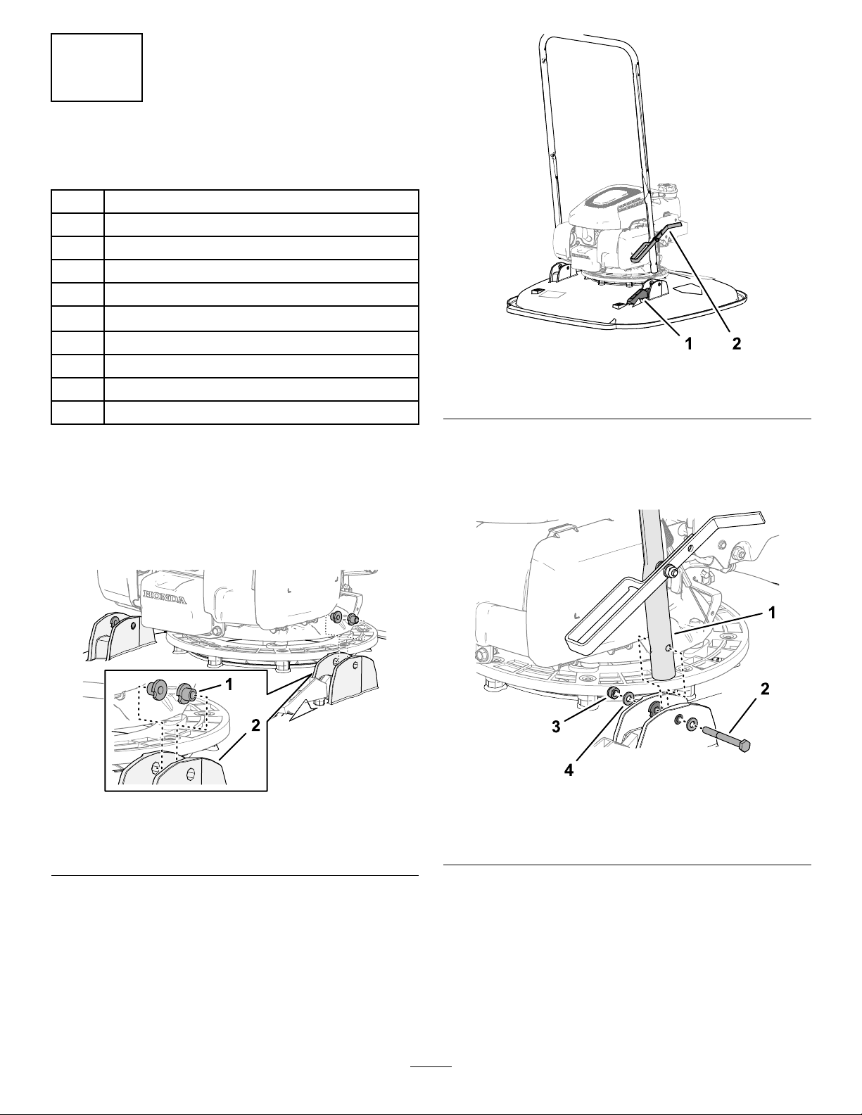
2
Montageduguidon
Piècesnécessairespourcetteopération:
4DouillesenT
2
Boulon(6x55mm)
6
Rondelle(6mm)
2
Contre-écrou(6mm)
2Bouton
2
Étrierleté
Blocdexation
1Partiesupérieureduguidon
1
Boulon(¼"x1¾")
1
Contre-écrou(¼")
Montagedelapartieinférieuredu
guidonsurlamachine
g364680
Figure6
1.Supportdecaleaupied2.Caleaupied
3.Alignezletroudansleguidonsurlestrous
desdouilles(Figure7)etxezleguidonsurla
machineàl'aided'unboulon(6x55mm),2
rondelles(6mm)etuncontre-écrou(6mm).
1.Insérez2douillesenTdanslesbridesde
montageduguidonsurleplateaudecoupe
(Figure5).
Figure5
1.DouillesenT2.Bridesdemontagedu
guidon(plateaudecoupe)
2.Alignezlacaleaupiedduguidonparrapport
supportsurleplateau(Figure6).
g364681
g364682
1.Partieinférieureduguidon3.Rondelle(6mm)
2.Boulon(6x55mm)4.Contre-écrou(6mm)
Figure7
4.Répétezl'opération3del'autrecôtédela
machine.
6

Assemblagedespartiesinférieure
etsupérieureduguidon
1.Alignezlestrousdanslapartiesupérieureetles
trousdanslapartieinférieureduguidon(Figure
8).
2.Serrezlecôtédelabarredeprésencede
l'utilisateurjusqu'àcequ'ilsortedelapartie
supérieure,puisdéposezlabarredelamachine
(Figure10).
Figure8
1.Partieinférieureduguidon
2.Bouton
3.Rondelle(6mm)
4.Partiesupérieuredu
guidon
5.Étrierleté
2.Fixezlapartiesupérieureduguidonsurlapartie
inférieureàl'aidede2étriersletés,2rondelles
(6mm)et2boutons.
Montageducâblesurlabarrede
présencedel'utilisateur
1.Insérezlaxationauboutdelagaineducâble
dansladouillesupérieuredublocdexation
(Figure9).
g364684
g367353
Figure10
3.Insérezlaxationducâbledansletroudu
supportdelabarredeprésencedel'utilisateur,
commemontréàlaFigure11.
g367355
Figure11
Figure9
1.Blocdexation2.Fixation(gaineducâble)
1.Support(barrede
présencedel'utilisateur)
g367356
4.Insérezl'extrémitédelabarredeprésencede
2.Fixationdecâble
l'utilisateurdansleguidon,serrezlégèrement
undescôtésdelabarreetinsérezlabarredans
leguidon(Figure12).
7

Figure12
5.Fixezleblocdexationsurlapartiesupérieure
duguidon(Figure13)àl'aideduboulon
(¼"x1¾")etducontre-écrou(¼").
3
Ajoutd'huiledanslemoteur
Aucunepiècerequise
Procédure
g367358
Important:Lecartermoteurdecettemachineest
videàlalivraison.Faitesl'appointd'huileavant
demettrelemoteurenmarche.
ClassedeserviceAPI:SJoumieux
Viscositédel'huile:10W-30
Capacitéducarterd'huile:0,40l
1.Amenezlamachinesurunesurfaceplaneet
horizontale.
2.Retirezlajaugedugoulotderemplissageet
essuyez-lasurunchiffonpropre(Figure14).
Figure13
1.Boulon(¼"x1¾")3.Blocdexation
2.Partiesupérieuredu
guidon
4.Contre-écrou(¼")
g367354
g364715
Figure14
3.Versezlentementl'huilemoteurspéciéedans
legoulotderemplissage(Figure15),puis
attendez3minutes.
8

Figure15
4.Insérezlajaugeaufonddugoulotde
remplissage,puisressortez-la.
5.Vériezleniveaud'huileindiquésurlajauge
(Figure16).
Remarque:Sivousremplissezexcessivement
lecartermoteur,vidangezl'excédentd'huile;
voirVidangedel'huilemoteur(page21).
Vued'ensembledu
produit
g364716
g364714
Figure17
Figure16
1.Leniveaud'huileestau
maximum.
2.Leniveaud'huileesttrop
élevé–vidangezune
partiedel'huile.
3.Leniveaud'huileesttrop
bas–ajoutezdel'huile
danslecarter.
6.Sileniveaud'huileestau-dessusdelalimite
supérieure,essuyezlajaugesurunchiffon
propreetrépétezlesopérations3à5jusqu'àce
queleniveauatteignelalimitesupérieure.
7.Insérezlajaugedanslegoulotderemplissage
etserrez-lasolidementàlamain.
1.Guidon4.Caleaupiedduguidon
2.Barredeprésencede
l'utilisateur
3.Plateaudecoupe
g364717
1.Poignéedulanceur5.Bouchonduréservoirde
2.Bougie6.Jauge
3.Filtreàair7.Protectiondusilencieux
4.Robinetd'arrivéede
carburant
5.Boutonsduguidon
g364713
Figure18
carburant
9
 Loading...