

Toro Reelmaster 5 Blade, Reelmaster 7 Blade, Reelmaster 11 Blade, 01007, 01005 Operator's Manual
...Page 1

Form No. 3312–270 Rev. H
Reelmaster 5, 7, & 11 Blade
Model No. 01005—Serial No. 40001 thru 70001 and Up
Model No. 01007—Serial No. 40001 thru 70001 and Up
Model No. 01011—Serial No. 40001 thru 70001 and Up
Operator ’s Manual
English (EN)
Page 2

Contents
Introduction
Introduction 2. . . . . . . . . . . . . . . . . . . . . . . . . . . . . . . .
Specifications 3. . . . . . . . . . . . . . . . . . . . . . . . . . . . . . .
General Specifications 3. . . . . . . . . . . . . . . . . . . . .
Optional Equipment 4. . . . . . . . . . . . . . . . . . . . . . .
Setting Up Instructions 5. . . . . . . . . . . . . . . . . . . . . . . .
Remove Mower From Carton 5. . . . . . . . . . . . . . . .
Check Wheel Hubs And Install Wheels 5. . . . . . . .
Gear Case Oil 5. . . . . . . . . . . . . . . . . . . . . . . . . . . .
Critical Adjustments 6. . . . . . . . . . . . . . . . . . . . . . . . . .
Check Reel Bearings And Mower Fasteners 6. . . .
Parallel Bedknife To Reel 6. . . . . . . . . . . . . . . . . . .
Set Height Of Cut 7. . . . . . . . . . . . . . . . . . . . . . . . .
Reel Bearing Adjustment 7. . . . . . . . . . . . . . . . . . .
Operating Instructions 8. . . . . . . . . . . . . . . . . . . . . . . .
Adjust Bedknife To Reel For Light Contact 8. . . . .
Causes of Poor Quality of Cut 9. . . . . . . . . . . . . . .
Maintenance 10. . . . . . . . . . . . . . . . . . . . . . . . . . . . . . . .
Lubrication 10. . . . . . . . . . . . . . . . . . . . . . . . . . . . . .
Grinding 10. . . . . . . . . . . . . . . . . . . . . . . . . . . . . . . .
Lapping 11. . . . . . . . . . . . . . . . . . . . . . . . . . . . . . . . .
Bedknife Replacement 11. . . . . . . . . . . . . . . . . . . . .
Reel, Roller and Wheel Bearing Adjustment 11. . . .
Mower Servicing Procedure Disassembly 12. . . . . .
Gear Case And Frame Assembly 16. . . . . . . . . . . . .
Roller Disassembly 17. . . . . . . . . . . . . . . . . . . . . . . .
Roller Assembly 17. . . . . . . . . . . . . . . . . . . . . . . . . .
The Toro General Commercial Products Warranty 20. .
Read this manual carefully to learn how to operate and
maintain your product properly. The information in this
manual can help you and others avoid injury and product
damage. Although Toro designs and produces safe
products, you are responsible for operating the product
properly and safely.
Whenever you need service, genuine Toro parts, or
additional information, contact an Authorized Service
Dealer or Toro Customer Service and have the model and
serial numbers of your product ready. The two numbers are
stamped on a plate which is located on the cross tube.
Write the product model and serial numbers in the space
below:
Model No.
Serial No.
This manual identifies potential hazards and has special
safety messages that help you and others avoid personal
injury and even death. Danger, Warning, and Caution are
signal words used to identify the level of hazard. However,
regardless of the hazard, be extremely careful.
Danger signals an extreme hazard that will cause serious
injury or death if you do not follow the recommended
precautions.
Warning signals a hazard that may cause serious injury or
death if you do not follow the recommended precautions.
1983, 2003 The The Toro Company
8111 Lyndale Avenue South
Bloomington, MN 55420-1196
Caution signals a hazard that may cause minor or moderate
injury if you do not follow the recommended precautions.
This manual uses two other words to highlight information.
Important calls attention to special mechanical
information and Note: emphasizes general information
worthy of special attention.
All Rights Reserved
Printed in the USA
2
Page 3

Specifications
General Specifications
Reel Drive
Reduction, Reel to
Wheels
Welded Reel
Bedknife & Bedbar
Bedknife to Reel
Adjustment
Wheels and Tires
Differential Disengaging over–running idler gear in gear train.
Width of Cut 30” (0.762 m)
Reel driven by wheels 75T ring gear to 10T pinion through 14T disengaging idler
gear.
7.5:1
Medium carbon steel, induction hardened blades are welded to seven steel spiders
which are mounted on a 1–1/2” (38 mm) diameter shaft. Tapered roller bearings
support reel shaft, and an adjusting nut compensates for bearing wear. Diameter of
11 blade reel is 7 inches (17.8 cm). 5 and 7 blade reels are 8” inches (20.3 cm).
Single edge high carbon steel knife attached to a fabricated steel bar; single screw
adjustment on adjustable rod ends.
Bedknife adjusts against reel, with positive adjustment control knob located at
center of bedbar. Adjustment knob contains detent with .001 inch (0.0254 mm)
movement of bedknife for each indexed position. Pivot point at top of bedbar is
greasable.
16” (0.406 m) diameter pneumatic wheels with tire and tube, studded tread,
stamped steel wheel and cast iron hubs; 16” (0.406 m) diameter semi pneumatic
tires with stamped steel wheels and cast iron hubs; 16” (0.4(06 m) diameter cast
iron wheels – one piece construction; 16” (0.406 m) diameter low profile
semi–pneumatic tires with stamped steel wheels and cast iron hubs; 18” (0.457 m)
semi–pneumatic tires with stamped steel wheels and cast iron hubs.
Height of Cut
Frequency of Clip
Chassis
Roller
11 Blade – .38 inches (9.5 mm) to 1.25 inches (32 mm) with 16” (0.406 m) dia.
wheel.
7 Blade – .75 inches (19 mm) to 1.75 inches (45 mm) with 16” (0.406 m) dia. wheel.
5 Blade – 1.25 inches (32 mm) to 2.25 inches (57 mm) with 16” (0.406 m) dia.
wheel
5 Blade – 2.00 inches (50 mm) to 3.00 inches (76 mm) with 18” (0.457 m) dia.
wheel
All adjustment are made in .040 inch increments.
11 Blade w/16” wheels – .58” clip (68 cuts per meter)
7 Blade w/16” wheels – .91” clip (43 cuts per meter)
5 Blade w/16’ wheels – 1.28” clip (31 cuts per meter)
5 Blade w/18” wheels – 1.51” clip (26 cuts per meter)
Ribbed cast iron gear cases with tubular cross members. Front cross member
provides easy attachment for the mower to the Reelmaster Universal and
Reelmaster Transport frames.
3–1/2” (88.9 mm) O.D. Iron pipe running on taper bearings double lip oil seal with
wear sleeves. Grease fittings provided.
3
Page 4

General Specifications (continued)
Width
41–1/2” (1.054 m) with iron wheels, 45” (1. 1 43 m) with semi–pneumatic tires.
Height
General Specifications
(approx.)
Note: Specifications and design subject to change without notice.
16” (0.406 m) or 18” (0.457 m) depending on tires.
Weight
11 Blade – 252 lbs. (114 kg)
7 Blade – 248 lbs. (112 kg)
5 Blade – 243 lbs. (110 kg)
All with 16” (0.406 m) semi–pneumatic tires (without draw bars).
Optional Equipment
16” (0.406 m) cast iron wheel Model No. 01336
16” (0.406 m) pneumatic tires Model No. 01323
16” (0.406 m) semi–pneumatic low
profile
18” (0.457 m) semi–pneumatic
tires
Roller Scraper Kit Part No. 47–4540
Grass Dispersion Shield Kit
(5 & 7 Blade)
Grass Dispersion Shield Kit
(11 Blade)
Adapter Kit Model No. 01050
Universal Frame Adapter Kit Part No. 47–2220
Model No. 01304
Model No. 01035
Part No. 51–0800
Part No. 47–5390
4
Page 5
Setting Up
Instructions
Remove Mower From Carton
1. Slit four corners of carton so sides lie flat.
2. Remove shipping caps from wheel hubs.
Note: Keep the shipping caps. They can be installed on
wheel hubs to prevent grinding dust from entering wheel
bearing whenever reel is ground.
4. Install drive wheels with capscrews and lockwashers
(Fig. 2). Do not try to install wheels over the shipping
caps.
Check Wheel Hubs And Install
Wheels
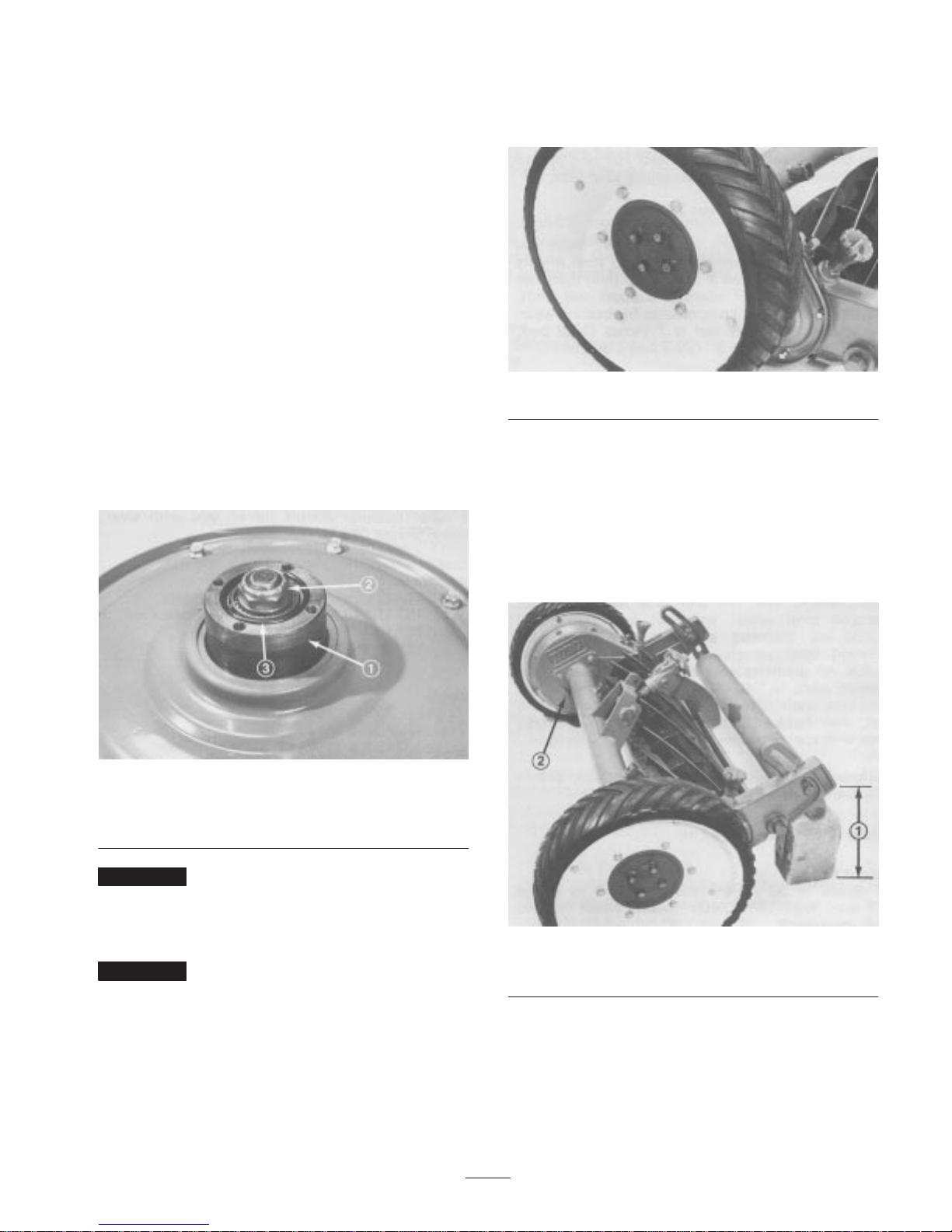
1. Rotate wheel hub (Fig. 1) to check bearing adjustment.
A slight drag must be felt when hub is rotated. If drag is
not evident, tighten wheel hub nut (Fig. 1) until slight
drag is felt when hub is rotated.
Figure 1
1. Wheel hub
2. Wheel hub nut
3. O–ring
Figure 2
Gear Case Oil
1. Position mower on a level surface.
2. Raise and block back of mower until there is
approximately 10–1/4 inches (0.260 m) between bottom
of gear case extending behind roller bracket and level
surface (Fig. 3).
Important Do not over–tighten wheel hub nut because
the bearing will wear rapidly.
2. Check O–ring to assure it is not damaged, and make
sure it is seated in inside diameter of wheel hub (Fig. 1).
Important An O–ring that is damaged or installed
incorrectly will allow oil to leak out of the gear case. If
enough oil leaks out, mechanical damage will likely result.
3. If pneumatic wheels are installed, set tire pressure at
35 psi (241.3 Kpa).
Figure 3
1. 10–1/4 inches 2. Filler plug
3. Remove filler plug from inside of each gear case
(Fig. 3). Check oil level in gear case: it should be level
with bottom of filler hole. If oil is level with bottom of
hole, reinstall filler plug.
5
Page 6
Important Check for oil leaks caused by a defective or
improperly installed O–ring or gasket, and loose side plate
bolts. Make all repairs before adding oil to gear cases.
4. If level of oil is low, fill gear case to point of
overflowing with SAE 80–90 gear lube and reinstall
filler plug. DO NOT OVERFILL.
Critical Adjustments
Check Reel Bearings And
Mower Fasteners
1. Rotate center adjusting knob until bedknife does not
contact reel. Try to spin the reel. If reel does not spin,
adjust reel bearings; refer to Reel Bearing Adjustment,
page 6. If reel spins freely, proceed to step 2.
2. Try to move reel back and forth. If reel can be moved,
reel bearings must be adjusted; refer to Reel Bearing
Adjustment, page 7.
3. Check and tighten all nuts, bolts, and screws to assure
all parts are secure.
4. Continue to check for light contact across full length of
bedknife using paper. If light contact is not evident,
bedknife is not parallel to reel.
5. Loosen nut on left bedbar pivot bolt enough to ease
turning of eccentric bolt.
6. Parallel bedknife to reel by rotating the left bed– bar
pivot bolt (Fig. 5). The left pivot bolt has an offset
thread which, when rotated, acts as a cam to raise or
lower the bedbar. On the left hand pivot bolt there is an
offset dot (Fig. 5) which denotes the thread of the bolt.
When the dot is in the up position (Fig. 5) the left end
of bedbar is raised. As bolt is turned clockwise and dot
is lowered, so is the left end of bedbar. Identification
dot is to be positioned within the rear (180) position
when adjusting.
Parallel Bedknife To Reel
1. Position mower on a level surface. Remove paint and
grease from bedknife and reel cutting edges.
2. Make sure throwout knobs (Fig. 4) are disengaged and
bedknife to reel contact is removed by turning bedknife
adjustment knob counterclockwise.
3. Insert a long strip of newspaper between reel blade and
bedknife. While rotating reel backward, turn bedknife
adjusting knob (Fig. 4) clockwise, one click at a time,
until paper is pinched lightly, which results in paper
being cut or a slight drag when paper is pulled.
Figure 5
1. Bedbar pivot bolt
7. Rotate left pivot bolt to raise or lower bedbar.
8. Insert a long strip of newspaper between reel blade and
bedknife. While rotating reel backward, turn bedknife
adjusting knob clockwise, one click at a time, until
paper is pinched lightly, which results in paper being
cut or a slight drag when paper is pulled.
9. When light contact is evident across full length of
bedknife, tighten pivot bolt nut, while holding bolt in
position and check to make sure pivot bolt did not
become misadjusted when tightened. Readjust as
required.
Important To make sure bedknife and reel are not
damaged while mowers are transported to or installed on
the towing frame, rotate bedknife adjusting knob
counterclockwise until bedknife does not touch the reel.
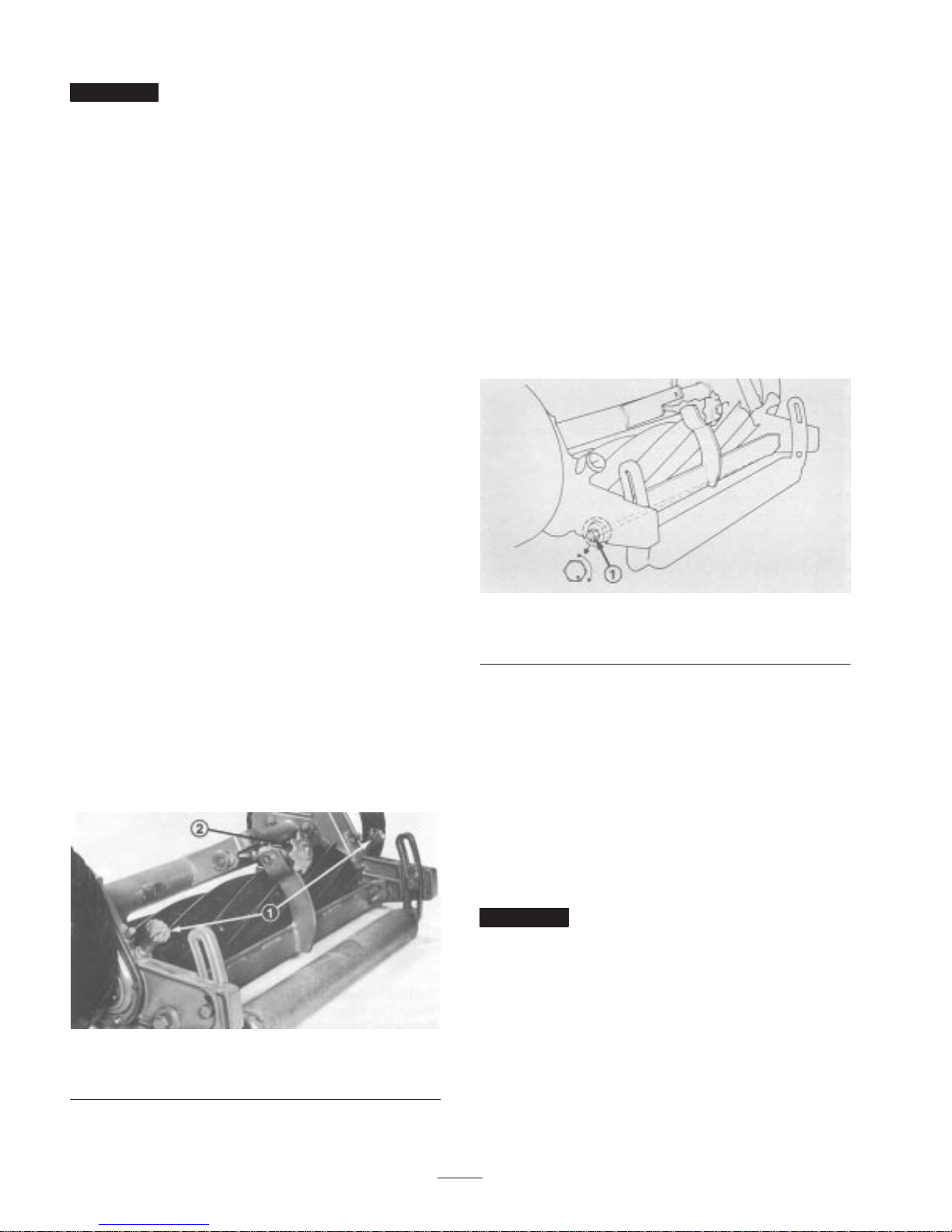
Figure 4
1. Throwout knobs 2. Bedknife adjusting knob
6
Page 7
Set Height Of Cut
Reel Bearing Adjustment
The height of cut is adjustable in approximately 3/32”
(2.38 mm) increments by raising or lowering rear roller.
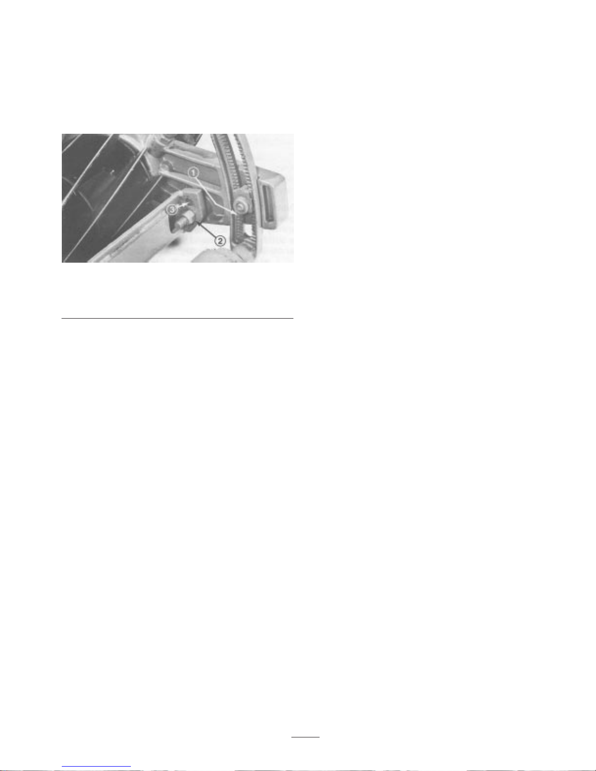
1. Loosen capscrews securing adjusting nuts in roller
brackets (Fig. 6).
Figure 6
1. Bottom edge of adjusting
nut
2. Position roller adjusting nuts in desired notches and
tighten capscrews. Make sure same number of notches
show below adjusting nuts.
2. 11 blade mounting hole
3. 5 & 7 blade mounting hole
If end play is evident in reel or if mower has been
disassembled, an adjustment to the reel bearing may be
necessary.
1. Remove (4) four screws securing left wheel to wheel
hub and remove wheel. Place wheel under gear case for
support.
2. Raise and block back of mower until there is 7 to 8
inches (0.178 to 0.203 m) between bottom of gear case
extending behind roller bracket and level surface.
3. Remove (3) three capscrews securing inspection cover
to gear case cover.
4. In small increments, rotate the adjusting nut on reel
shaft, in clockwise direction to remove all end play
from the reel. Make sure to hold reel so it cannot rotate.
5. When end play is removed, rotate nut an additional 1/4
turn to preload the bearing.
6. Reinstall inspection cover and the wheel.
3. If a higher height of cut is desired, every notch moved
adds approximately 3/32 of an inch (2.38 mm) to the
cutting height.
Note: These are bench settings. The mower will cut at a
different height in turf because of grass conditions and the
weight of the mower.
4. To make a finer adjustment to cutting height or to adjust
roller, adjusting nut may be moved 1/2 notch or 3/64 of
an inch (1.19 mm) by using the following procedure:
A. Remove capscrew and adjusting nut securing roller
bracket to gear case. Do not move roller bracket.
B. Reposition capscrew and adjusting nut to upper hole
in gear case.
C. Slide roller bracket up or down 1/2 notch to position
adjusting nut into correct notch and tighten
capscrew.
7
Page 8

Operating
Instructions
5. Check the reel “carry over” by spinning reel backward
again. Reel should rotate one to two complete
revolutions. Less than one revolution indicates heavy
contact, which means the bedknife and reel must be
readjusted for light contact; refer to steps 1, 3 and 4.
Adjust Bedknife To Reel For
Light Contact
Important After mower is set up and installed on the
towing frame, the bedknife and reel must be adjusted for
light contact. Adjust bedknife to reel while mower is setting
on the grass to be cut because the force of turf against
underside of bedknife during actual operation must be
duplicated to ensure correct setting. To assure sharp cutting
edges, bedknife and reel must have light contact.
1. Stand behind the mower.
2. Disengage reel throwout knobs (Fig. 7). Carefully spin
reel backward to insure free movement.
3. While spinning reel backward, rotate bedknife adjusting
knob counterclockwise (Fig. 7) until bedknife does not
touch reel blades.
6. At the beginning of the cutting day, when reels are cold,
engage the reel throwout knobs (Fig. 7). Operate
mowers for 15 to 20 minutes so the bedknife and reel
reach normal operating temperature; then stop
operation. Next, disengage reel throwout knobs and spin
reel backward. A whispering sound, not clicking,
should be emitted, and this assures correct adjustment.
If a whispering sound is not heard, bedknife and reel
must be readjusted; refer to steps 3–5. By contrast,
when reels are warm from being used, use only steps
1–5 to maintain light contact between bedknife and reel.
Important Never adjust bedknife to reel for light
contact if mowers are cold because the increase in
temperature during operation could cause the metal to
expand and result in heavy contact. Heavy contact causes
uneven bedknife wear and poor quality of cut. However,
light contact between bedknife and reel, which is desirable,
minimizes wear and keeps cutting edges sharp. Adjust for
light contact every four hours or sooner, even though
quality of cut is acceptable. When mowers are operated in
sparse grass or temperature of air is high, the adjustment
for light contact must be checked even more frequently to
avoid heavy contact between the bedknife and reel. If
mowers are not operated for a short time, one hour after
any use, check for light contact after resuming operation for
15 to 20 minutes; refer to steps 1–6.
Figure 7
1. Throwout knobs 2. Bedknife adjusting knob
4. While spinning reel backward, rotate adjusting knob
clockwise (Fig. 7), one click at a time, until light
contact of bedknife and reel is noticed or a whispering
cutting sound is heard.
Note: Spring arm (clicker) may be adjusted for positive
detent by loosening capscrews securing spring arm to
adjustment arm retainer, adjust until a solid clicking sound
is achieved when adjusting knob is turned, and retightening
capscrews.
Mower Use
1. Mowing Speed – The mower is designed to cut grass
well at any ground speed between 1 and 6 mph (1.6 and
9.66 km/hr) but for most turf conditions, ground speeds
of 4–6 mph (6.4–9.66 km/hr) produce the best quality
of cut. Ground speed, however, must be reduced when
turning because excessive speed will cause outside
mowers to bounce and skip on the turf. Excessive heat,
caused by the reel spinning too fast, can also damage
the bedknife and reel. Since grass lubricates the
bedknife and reel during operation, slow down when
cutting sparse grass, extremely dry grass, or when
trimming. Any lack or significant reduction of
lubrication produces excessive heat build–up and
subsequently, heavy contact between bedknife and reel,
which results in uneven bedknife wear and poor quality
of cut. Therefore, reels must be disengaged and stopped
before mowers are transported across parking lots,
roads, or whenever lubrication is minimal.
2. Height–of–Cut – To determine the effective
height–of–cut, the length of the grass to be cut must be
checked. Height–of–cut should be set and turf mowed
frequently so no more than 1/3 of the leaf is cut off. If
8
Page 9

mower is equipped with pneumatic tires, pressure must
be maintained at 35 psi (241.3 kpa) (Fig. 8). Low tire
pressure can cause bedknife to dip into the grass and
scalp the turf. An uneven cut will likely result.
Figure 8
3. Operating Sound – A mower that is adjusted correctly
gives off a whispering sound when operated. If there are
buzzing, clicking, or metallic sounds, the mower has
probably been operated with heavy contact between
bedknife and reel. The reel or bedknife could also have
hit a foreign object. A noisy mower must be stopped,
repaired, and adjusted or severe damage will result.
Figure 9
Note: Rifling is the uneven or wavy condition that
develops on bedknife and reel when there is heavy contact
between these two parts (Fig. 10). Streaks of uncut grass
and an overall poor quality of cut are signs of rifling.
Grinding the bedknife and reel is the only way to repair a
rifled mower.
4. Mowing Pattern – To prevent grass from lying down
and improve appearance of turf, alternate mowing
directions if possible, each time an area is cut.
Causes of Poor Quality of Cut
1. Bedknife/Reel Contact (Fig. 9) – There must be light
contact between bedknife and reel to keep cutting edges
sharp and to produce an excellent quality of cut. By
contrast, mowers operated with– out light contact allow
abrasive materials and grass to pass between the
bedknife and reel. This eroding action rounds off the
bedknife and reel cutting edges, which results in a poor
quality of cut. If cutting edges become round, bedknife
and reel must be lapped. Excessive rounding off of
cutting edges may require that bedknife and reel be
ground and lapped. Never compensate for round cutting
edges by tightening bedknife adjusting knob until there
is heavy contact because the bedknife and reel will wear
unevenly and cause “rifling”.
Figure 10
2. Noise – A mower that has sharp cutting edges and is
adjusted with light contact will emit a desirable
whispering sound when reel is spinning. By contrast,
buzzing, clicking, or metallic sounds during operation
indicate that mower is probably being operated with
heavy contact between bedknife and reel. Heavy contact
causes uneven or wavy wear on the bedknife and reel
cutting edges. Grinding is required to repair a damaged
bedknife and reel. Although the bedknife and reel are
adjusted correctly for light contact, notches will
eventually develop at both ends of the bedknife. These
notches must be rounded off or filed flush with cutting
edge of bedknife to assure smooth operation.
3. Loose Reel Bearings – If reel bearings are suspected to
be loose, check them immediately or extensive damage
may result; refer to Reel Bearing Adjustment, page 7.
4. Hitting a Foreign Object – The bedknife and reel
cutting edges can be damaged if a foreign object is hit.
The damage, if it is not too severe, can be repaired in
the field. Start by filing down high spots on the
9
Page 10

bedknife and reel (Fig. 11). Use a ball peen hammer to
straighten any reel blades that may be bent. Since
bedknife usually springs away from the reel upon
impact, bedknife must be adjusted; refer to Parallel
Bedknife to Reel, page 6.
Figure 11
Maintenance
Lubrication
1. The gear cases have been fully lubricated at the factory.
Once each season, drain and clean the right and left gear
cases. When gear cases are clean, add SAE 140 gear
lube; refer to Gear Case Oil, page 5.
2. The mowers should be greased every 8 hours of
operation with Heavy Duty 2 wheel bearing grease, to
obtain maximum life. This grease can be used on all
greasing points (Fig. 12). When pressure is felt while
greasing the roller, bearing cavity between seals if full.
DO NOT CONTINUE TO GREASE BECAUSE
INNER BEARING SEAL MAY BE DAMAGED.
Figure 12
Important Do not use high pressure hose to clean areas
where there are seals or bearings because foreign matter
will likely be forced into the bearing. The result will be
rapid seal and bearing deterioration. Grease the mower
immediately after cleaning. Failure to do so may cause
damage to the bearings or other components.
Grinding
Note: For detailed sharpening information, order the Toro
Sharpening Reel and Rotary Mowers Manual, from the
Commercial Service Department.
New and old bedknives should be ground attached to the
bedbar; this ensures rigidity during grinding and insures a
true knife. Refer to figure 13 when grinding tHe knives and
obtain as near as possible the relief angles indicated. In
grinding, avoid a hard contact between knife and grinding
wheel. If hard contact occurs, excessive heat buildup will
take place, causing premature wearing of the grinding
wheel and reduced life of the knife.
10
Page 11

Figure 13
The land area and relief angle of reel blade are pointed out
in figure 14. The land area is that part of the reel blade that
actually comes in contact with the bedknife and cuts the
grass in a scissors action. The relief or back grind angle is
ground into reel blade to provide clearance or relief be–
hind contacting edges to reduce drag or friction.
Recommended relief angle is 15 degrees.
If the reel blade edges and bedknife edge are slightly
rounded and do not have severe nicks, lapping only with a
lapping compound may restore the edges and match.
Oftentimes a mower is deemed by users to need grinding
when reel bearing adjustment, bedknife adjustment and/or
lapping is all that is necessary.
Lapping
Mowers are set up as follows:
1. Remove the right hand wheel.
2. Place wheel under gear case for support.
3. Remove the reel pinion cover (Fig. 15).
Figure 14
Note: After a reel has run for an extended period of time
the blade contact point or land area will keep getting wider
and eventually will be full blade width. This is normal and
does not mean that the reel has to be reground to stay
effective. A cutting unit can cut effectively with full width
blades if the adjustment is checked frequently to maintain
sharp cutting edges.
After reel and bedknife have been ground, perform the
following adjustments:
1. Set Height–of–Cut, page 7.
2. Parallel Bedknife to Reel, page 6.
Note: As the reel blades continue to run against the
bedknife a slight burr will appear on the front cutting edge
surface the full length of the bedknife. If a file is
occasionally run across the front edge to remove this burr,
improved cutting can be obtained.
Figure 15
1. Reel pinion cover
4. Disengage the reel.
5. Connect the lapping machine coupler to the nut on the
end of the reel shaft.
When lapping, use a good grade of commercial lapping
compound. A medium grit should be for initial lapping and
a fine grit for finishing. A solution of one part liquid
detergent and two parts lapping compound is
recommended. The liquid detergent greatly eases washing
away the compound when finished. Water soluble oil may
also be used as a compound carrier.
Note: Lapping solution must be kept in free flowing
condition to get even distribution on bedknife and reel.
The lapping procedure is as follows:
1. Adjust bedknife to reel so light contact is evident.
2. Operate the lapping machine so the reel turns in a
reverse direction. Apply lapping solution continuously
and maintain light bedknife to reel contact.
3. Stop lapping machine periodically to check cutting
surfaces for sharpness. Continue lapping until sharp
cutting edges have been restored.
11
Page 12

Note: If the cutting edges are severely rounded, both
sharpening and lapping may be required.
4. Wash off all lapping solution. Using paper, check for
sharpness along entire length of each reel blade. If
paper cannot be cut cleanly along entire length of each
reel blade, continued lapping is necessary.
Bedknife Replacement
1. To replace the bedknife, remove the eleven (11) screws
holding the knife to the bed bar; replace the knife and
reinstall the screws. All screws should be lubricated
with oil and torqued to 250–300 in.–lb
(28.3 – 33.9 N.m). The screws should be tightened by
starting at center of the bedknife and alternating until all
screws are secured.
2. True the bedknife attached to the bedbar by grinding.
Refer to the TORO SHARPENING REEL and
ROTARY MOWERS MANUAL.
Mower Servicing Procedure
Disassembly
1. Remove four (4) capscrews securing wheel to wheel
hub. Remove wheel from hub.
2. Remove O–ring from inside of hub (Fig. 16).
3. After bedknife has been ground and is “true”, perform
the following adjustments:
Reel, Roller and Wheel Bearing
Adjustment
After the initial 30 operating hours, check the reel bearing,
roller bearing, and wheel bearing. Thereafter, check these
parts every 200–250 operating hours. If necessary, adjust
the reel bearing (See Reel Bearing Adjustment, page 7. If
necessary, adjust the roller bearing (See Roller Assembly,
page 17). If necessary, adjust the wheel bearing (See Check
Wheel Hubs, page 5.)
Figure 16
3. Remove wheel hub nut from axle shaft (Fig. 17).
Figure 17
1. Wheel hub nut
4. Place oil pan under gear case assembly. Loosen the ten
(10) capscrews securing cover to gear case (Fig. 18).
12
Page 13

Figure 18
1. Mounting capscrews
5. Separate cover from gear case and allow oil to drain.
Remove cover and discard gear case gasket (Fig. 19).
Figure 19
1. Gasket 2. Double lip seal
Figure 20
1. Drift pin punch
2. Bearing cups
3. Hub
8. Remove inner cone and O–ring from axle shaft
(Fig. 21).
6. Remove double lip seal (Fig. 19) from cover if worn or
damaged. The ring gear hub and gear assembly can be
removed from axle shaft as soon as gear case cover is
removed.
7. Use a drift pin punch to remove bearing cups from hub
(Fig. 20).
Note: Access is provided in the bore for drift pin punch.
Figure 21
1. O–ring 2. Bearing cones
9. To prevent the reel from turning, place a wooden block
between reel blades and axle shaft.
13
Page 14

Using a socket wrench, remove ratchet gear stud securing
ratchet gear (Fig. 22). Remove left–hand ratchet gear stud
by rotating it clockwise. Remove right–hand ratchet gear
stud by rotating it counterclockwise. Removal of the ratchet
gear stud will free ratchet gear (Fig. 22).
Figure 24
1. Splined shaft
Figure 22
1. Rachet gear stud
2. Rachet gear
3. Nut
4. Pinion gear
10.Remove needle bearing from ratchet gear using a sleeve
and arbor press (Fig. 23).
Figure 23
11. (Left end) Remove nut securing pinion gear to reel shaft
and slide gear off splined shaft (Fig. 24).
12.(Right end) Remove nut securing pinion gear to reel
shaft. Insert a pry bar in groove provided and pry off
pinion gear. Remove woodruff key from key way in reel
shaft (Fig. 25).
Figure 25
14
Page 15

13.Remove the lower compression spring. Disassemble the
ratchet ring from the ratchet gear ring by removing
three (3) locknuts and prying equally around the ratchet
ring (Fig. 26). Be extremely careful to prevent damage
to the mating surfaces.
Figure 26
1. Lower compression
spring
2. Locknuts
3. Rachet ring
14.For removal of the throwout handle (Fig. 27), O–ring
and finger, drive pin from throwout handle. Remove
throwout sleeve by turning counterclockwise.
Figure 27
1. Throwout handle
Note: When replacing O–ring, sleeve must be removed
(Fig. 28). Throwout sleeve need only be loosened for
removal of rachet ring gear.
Figure 28
1. O–ring 2. Sleeve
15.Lift out the upper compression spring. Remove rachet
gear ring from gear case.
16.Remove roller adjustment bolts and nuts from each side
of roller (Fig. 29).
15
Page 16

Figure 29
17.Loosen locknuts allowing removal of Allen head set
screws securing bedbar to bedbar retainer (Fig. 30).
Note: When reinstalling bedbar to bedbar retainer, center
bedbar retainer, tighten setscrews until seated and tighten
locknuts.
Figure 30
1. Locknuts 2. Allen head set screws
Figure 31
1. Bearing removal tool, part no. 49–8060
Note: Remove any rust from cross tube shaft to prevent
binding. Clean gear case with solvent. If studs have been
removed, apply Permatex No. 2 to threads.
22.Remove stub axle shaft from gear case by loosening
locknut and tapping with soft head mallet (Fig. 32).
18.Remove pivot bolts and nuts securing bedbar assembly
to gear cases (Fig. 29).
19.Remove three nuts securing each gear case to cross
tube. Using a soft head mallet, drive gear cases off cross
tube.
20.Bearing and gear case will now slide off left end of reel
shaft.
Note: To aid in the removal of reel bearings, a Bearing
Removal Tool, Part No. 49–8060, is available from your
Authorized Toro Distributor.
21.Remove bearing and gear case from right end of reel
shaft (Fig. 31).
Figure 32
1. Stub axle shaft
16
Page 17

Gear Case And Frame
Assembly
1. Apply Permatex #2 to serrations on drive tube studs and
press into gear case.
2. Apply Never Seez to threads and mount stub axles to
gear cases and secure with locknuts. Tighten locknuts to
40–55 ft. lb.
3. Press seal and bearing cup into right hand gear case.
Make sure plastic seal guard is installed over seal boss.
15.Place O–ring into groove on right hand throwout finger,
coat ring with heavy oil or grease, and slide through
sideplate, making sure that O–ring does not get
damaged. Install throwout sleeve over throwout finger
and tighten securely in gear case.
16.Slide throwout handle over finger and secure in place
with drive lock pin.
17.Position woodruff key in key slot in reel shaft and slide
on pinion gear.
18.Secure nut (left hand thread) on right hand reel shaft.
4. Slide gear case onto right hand end of reel shaft (key
slot end).
Note: Use caution not to damage seal in gear case when
inserting reel shaft.
5. Tap bearing cone onto reel shaft just far enough to
allow insertion of woodruff key and pinion gear.
Important Right hand bearing must be pressed onto
reel shaft by tightening pinion gear nut. DO NOT PRESS
ON OTHERWISE.
6. Install woodruff key, pinion gear, and nut and tighten
until gear bottoms out on reel shaft (left hand thread).
7. Remove nut, pinion gear and woodruff key before
continuing assembly.
8. Mount cross tube to right hand gear case and secure
finger tight with (3) lockwashers and nuts.
9. Press seal and bearing cup into left hand gear case.
Make sure plastic seal guard is installed over seal boss.
10.Slide gear case onto left hand end of reel shaft and gear
case studs into mounting holes in cross tube.
Note: Use caution not to damage seal in gear case when
inserting reel shaft.
11. Secure gear case to cross tube with (3) lockwashers and
nuts. Tighten nuts on both ends of cross tube to
80–90 ft.–lb.
12.Slide bearing cone onto left hand end of reel shaft and
into gear case.
13.Assemble the right hand ratchet gear ring over the shaft
and insert two (2) compression springs.
14.Assemble right hand ratchet ring over ratchet gear ring
and seat with a driver and hammer. Secure entire
assembly with (3) three stop nuts. Nuts should be drawn
up evenly and gradually to 14–22 ft. lb.
(19.04–29.8 N–m) to prevent breaking the ratchet ring.
Note: Ensure that assembly will ratchet. If assembly does
not ratchet, back nuts off slightly.
19.Assemble the ratchet gear and bearing assembly to right
hand, ratchet gear ring and secure with right hand
ratchet gear stud.
20.On the left side, assemble ratchet gear ring over the reel
shaft and insert (2) compression springs.
21.Assemble left hand ratchet ring over the ratchet gear
ring and seat with a driver and hammer. Secure entire
assembly with three (3) stop nuts. Nuts should be drawn
up evenly and gradually to 14–22 ft. lb.
(19.04–29.8 N.m) to prevent breakage of the ratchet
ring.
Note: Ensure that assembly will ratchet. If assembly does
not ratchet, back nuts off slightly.
22.Place O–ring into groove on left hand throwout finger,
coat ring with heavy oil or grease, and slide through
sideplate, making sure that O–ring does not get
damaged. Install throwout sleeve over throwout finger
and tighten securely in gear case.
23.Slide throwout handle over finger and secure in place
with a drive lock pin.
24.Aligning mark on pinion gear with mark on reel shaft
slide gear onto spline shaft.
25.Instal new nut (right hand thread) on left hand reel shaft
but do not tighten. When mower is completely
reassembled adjust reel bearing, refer to Adjusting Reel
Bearing, page 7.
26.Assemble the ratchet gear and bearing assembly to the
left hand reel ratchet gear ring and secure with the left
hand ratchet gear stud.
27.Mount bedbar to gear cases with shoulder bolts, rubber
spacers, plastic washers and locknuts. Use bottom
mounting hole in bedbar for 1 1 blade reels and top
mounting hole for 5 and 7 blade reels. When installing
left hand shoulder bolt (offset thread) thread the bolt in
until it touches rubber spacer, then back it out one
complete turn and tighten nut. Do not back out right
hand bolt. This will allow bedbar adjustment. Refer to
Parallel Bedknife to Reel, page 6.
28.Position roller bracket assembly in slots of gear case.
17
Page 18

29.Position right hand and left hand roller adjusting nuts
on roller bracket assemblies. Secure in place with
capscrews and lockwashers.
30.Press bearing cups in ring gear hub. Assemble bearing
cone to left side of stub shaft. Place large ring gear and
hub assembly over stub shaft and bearing cone.
31.Place another bearing over stub shaft and into ring gear
hub.
32.Position wheel hub nut on stub shaft and run down with
an open end wrench. Adjust bearing by tightening nut
until slight drag is felt when wheel bolt is rotated.
33.Press seal into gear case cover. Position gasket on gear
case. Lightly lubricate wheel hub seal in gear case
cover.
34.Position left hand gear case cover and secure with ten
(10) self tapping screws. Torque screws to approx. 125
in. lbs. (14.1 N–m) evenly and gradually.
35.Add approximately 15 ounces (0.44 1) of SAE 80–90
gear lubricant to gear. DO NOT OVERFILL.
5. Remove bearing cones from each end of roller.
6. Remove bearing cups with caution.
7. Remove inner seals by using a seal remover.
Roller Assembly
1. Lightly oil lips of inner seals. Install inner seals on each
end of roller, making sure that garter springs face
inboard.
2. Replace bearing cups and insert bearing cones into
roller.
36.Place O–ring into recess in wheel hub.
37.Secure the wheel to the wheel hub with four (4)
capscrews.
38.Repeat steps 30–37 on opposite side.
Roller Disassembly
As viewed from rear
Figure 33
1. Remove brackets and washers from each end of roller
and inspect bushings.
As viewed from rear
Figure 34
3. Lightly oil lips of outer seals. Install outer seals on each
end of roller, making sure that garter springs face
inboard.
4. Slide one (1) sleeve onto roller shaft against double jam
nuts.
5. Wrap threaded area of roller shaft with cellophane tape
to protect seals, and carefully slide shaft through
right–hand side of the roller. Slide roller shaft into roller
until it penetrates the inner most oil seal on the
right–hand side.
6. Pour approximately one (1) pint (16 ounces [0.0296 l)
of SAE 90 or 140 gear oil into the roller housing.
7. After oil has been added, carefully push roller shaft
through the entire roller assembly. Remove cellophane
tape.
8. Install sleeve on roller shaft and slide up against bearing
cone.
2. Remove elastic stop nut.
Note: After elastic stop nut has been removed, slide sleeve
off roller shaft. Point end of roller downward into a
container, at the same time pulling roller shaft out, allowing
lubricant to drain from roller.
3. If roller shaft is to be replaced, remove double jam nuts.
4. Remove remaining sleeve and seals from both ends of
roller.
9. Install elastic stop nut and secure by holding double jam
nuts. Tighten elastic stop nut (Fig. 35).
Note: Tighten elastic stop nut until all axial and radial
motion has been removed from the roller shaft and
bearings. Ensure that roller rotates freely on shaft.
10.Grease bearings with Heavy Duty 2 wheel bearing
grease.
11. Reinstall washers and install left and right–hand bracket
and bushing assemblies.
18
Page 19

Figure 35
Important After the mower has been completely
assembled, perform the following critical adjustments:
A. Check Reel Bearings and Mower Fasteners, page 6.
B. Set Height–of–Cut, page 7.
C. Parallel Bedknife to Reel, page 6.
When the adjustments have been completed, move the
mower to a turf area and adjust the bedknife to reel (See
Adjust Bedknife to Reel For Light Contact, page 8).
19
Page 20

20
Page 21

The Toro General Commercial Products Warranty
A Two-Year Limited Warranty
Conditions and Products Covered
The Toro Company and its affiliate, Toro Warranty Company,
pursuant to an a g r eement between them, jointly warrant your 1996
or newer Toro Commercial Product (“Product”) purchased after
January 1, 1997, to be free from defects in materials or
workmanship for tw o years or 1500 operational hours*, whichever
occurs first. Where a warrantable condition exists, we will repair the
Product at no cost to you including diagnosis, labor, parts, and
transportation. This warranty begins on the date the Product is
delivered to the original retail purchaser.
* Product equipped with hour meter
Instructions for Obtaining Warranty Service
You are responsible for notifying the Commercial Products
Distributor or Authorized Commercial Products Dealer from whom
you purchased the Product as soon as you believe a warrantable
condition exists.
If you need help locating a Commercial Products Distributor or
Authorized Dealer, or if you have questions regarding your
warranty rights or responsibilities, you may contact us at:
Toro Commercial Products Service Department
Toro Warranty Company
8111 Lyndale Avenue South
Bloomington, MN 55420-1196
952-888-8801 or 800-982-2740
E-mail: commercial.service@toro.com
Owner Responsibilities
As the Product owner, you are responsible for required maintenance and adjustments stated in your operator’s manual. Failure
to perform required maintenance and adjustments can be grounds
for disallowing a warranty claim.
Items and Conditions Not Covered
Not all product failures or malfunctions that occur during the
warranty period are defects in materials or workmanship. This
express warranty does not cover the following:
• Product failures which result from the use of non-Toro
replacement parts, or from installation and use of add-on,
modified, or unapproved accessories
• Product failures which result from failure to perform required
maintenance and/or adjustments
• Product failures which result from operating the Product in an
abusive, negligent or reckless manner
• Parts subject to consumption through use unless found to be
defective. Examples of parts which are consumed, or used up,
during normal Product operation include, but are not limited to,
blades, reels, bedknives, tines, spark plugs, castor wheels,
tires, filters, belts, etc.
• Failures caused by outside influence. Items considered to be
outside influence include, but are not limited to, weather,
storage practices, contamination, use of unapproved coolants,
lubricants, additives, or chemicals, etc.
• Normal “wear and tear” items. Normal “wear and tear” includes,
but is not limited to, damage to seats due to wear or abrasion,
worn painted surfaces, scratched decals or windows, etc.
Parts
Parts scheduled for replacement as required maintenance are
warranted for the period of time up to the scheduled replacement
time for that part.
Parts replaced under this warranty become the property of Toro.
T oro will make the final decision whether to repair any existing part
or assembly or replace it. Toro may use factory remanufactured
parts rather than new parts for some warranty repairs.
General Conditions
Repair by an Authorized Toro Distributor or Dealer is your sole
remedy under this warranty.
Neither The Toro Company nor Toro Warranty Company is
liable for indirect, incidental or consequential damages in
connection with t h e use of the Toro Products covered by this
warranty, including any cost or expense of providing substitute equipment or service during reasonable periods of
malfunction or non-use pending completion of repairs under
this warranty. Except for the Emissions warranty referenced
below, if applicable, there is no other express warranty. All
implied warranties of merchantability and fitness for use are
limited to the duration of this express warranty.
Some states do not allow exclusions of incidental or consequential
damages, or limitations on how long an implied warranty lasts, so
the above exclusions and limitations may not apply to you.
This warranty gives you specific legal rights, and you may also
have other rights which vary from state to state.
Note regarding engine warranty: The Emissions Control System
on your Product may be covered by a separate warranty meeting
requirements established by the U.S. Environmental Protection
Agency (EPA) and/or the California Air Resources Board (CARB).
The hour limitations set forth above do not apply to the Emissions
Control System Warranty. Refer to the Engine Emission Control
Warranty Statement printed in your operator’s manual or contained in the engine manufacturer’s documentation for details.
Countries Other than the United States or Canada
Customers who have purchased Toro products exported from the United States or Canada should contact their Toro Distributor (Dealer)
to obtain guarantee policies for your country, province, or state. If for any reason you are dissatisfied with your Distributor’s service or
have difficulty obtaining guarantee information, contact the Toro importer. If all other remedies fail, you may contact us at Toro Warranty
Company.
Part No. 374-0031 Rev. –
 Loading...