

Page 1
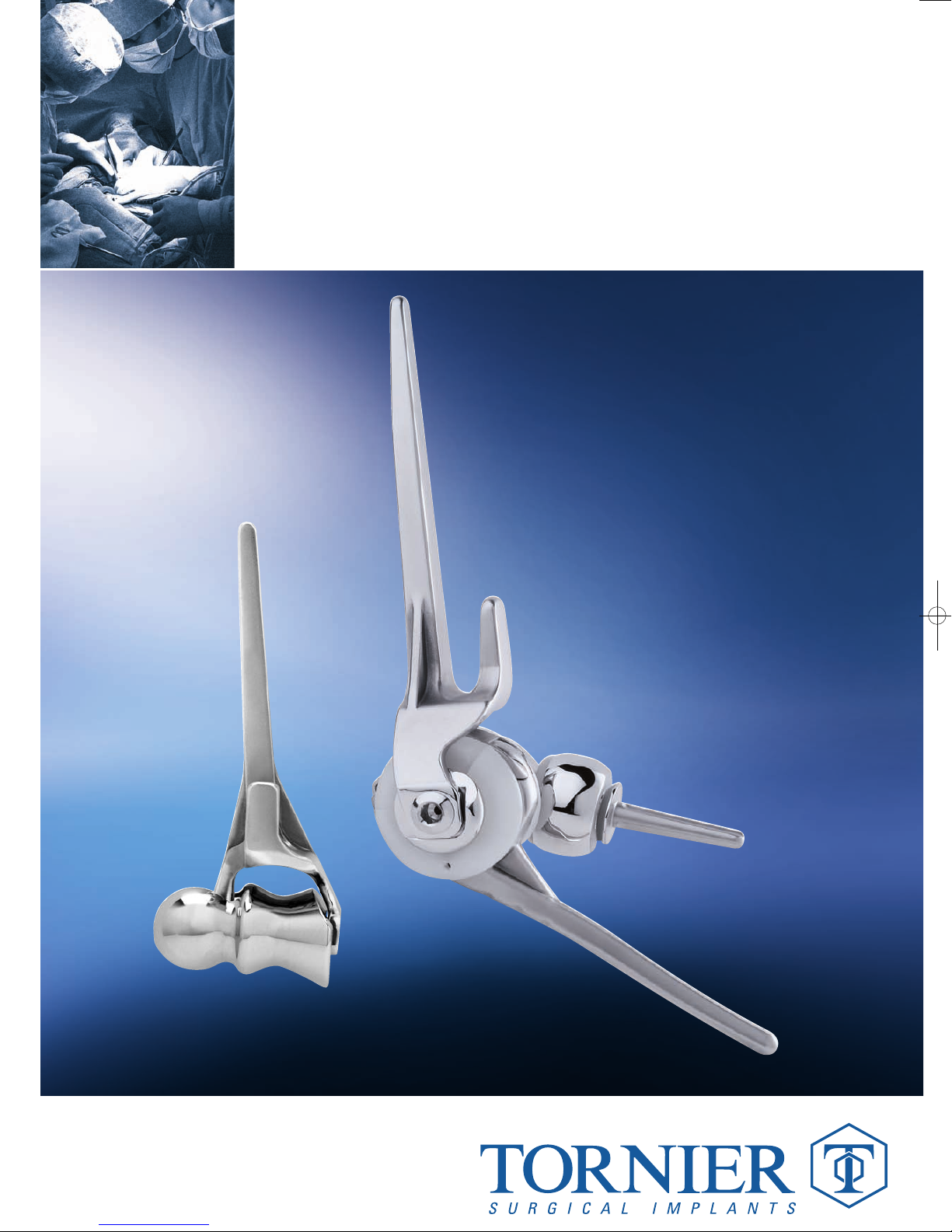
Surgical
Technique
Elbow Prosthesis
Latitude
®
www.tornier.com
UCLT101
Page 2

TABLE OF CONTENTS
TABLE OF CONTENTS
1. DESIGN RATIONALE
2. ANATOMICAL DESIGN VALIDATION
1. Humerus
2. Ulna
3. Radial head
3. PRECISION INSTRUMENTATION
4. INDICATIONS AND CONTRAINDICATIONS
1. Indications for use
2. Contraindications
5. LATITUDE ANATOMIC SURGICAL TECHNIQUE
(Hemi elbow prosthesis)
6. EXPOSURE
7. HUMERAL PREPARATION
1. Flexion-extension axis determination
2. Humeral Offset Determination
Latitude Elbow Prosthesis
3. Humeral Distal Preparation
8. ULNAR PREPARATION
(triceps splitting approach)
1. Radio-Ulnar Cutting guide Positioning
2. Ulnar canal Broaching
3. Ulnar canal reaming for standard stem
p. 3
p. 4-7
p. 8-9
p. 9
p. 11
p. 12-13
p. 14-23
p. 24-29
Shawn O’Driscoll, MD, PhD (Mayo Foundation), Ken Yamaguchi, MD (Washington University, Barnes Jewish Hospital)
Latitude Elbow Prosthesis Surgical Technique UCLT101
9. ULNAR TRIAL AND RADIUS PREPARATION
10. TRIAL AND REDUCTION
1. Unlinked
2. Linked
11. FINAL IMPLANT ASSEMBLY
12. CEMENT TECHNIQUE AND BONE GRAFT
13. SUTURE TECHNIQUE AND CLOSURE
14. RADIO-ULNAR TRICEPS ON CUTTING GUIDE
15. REVISION
INSTRUMENTATION
The Latitude®surgical technique has been developed in conjunction with:
Graham King, MD, MSc (University of Western Ontario)
2
p. 30-31
p. 32-33
p. 34
p. 34-36
p. 37
p. 38
p. 39
p. 40-42
Page 3
DESIGN RATIONALE
1. DESIGN RATIONALE
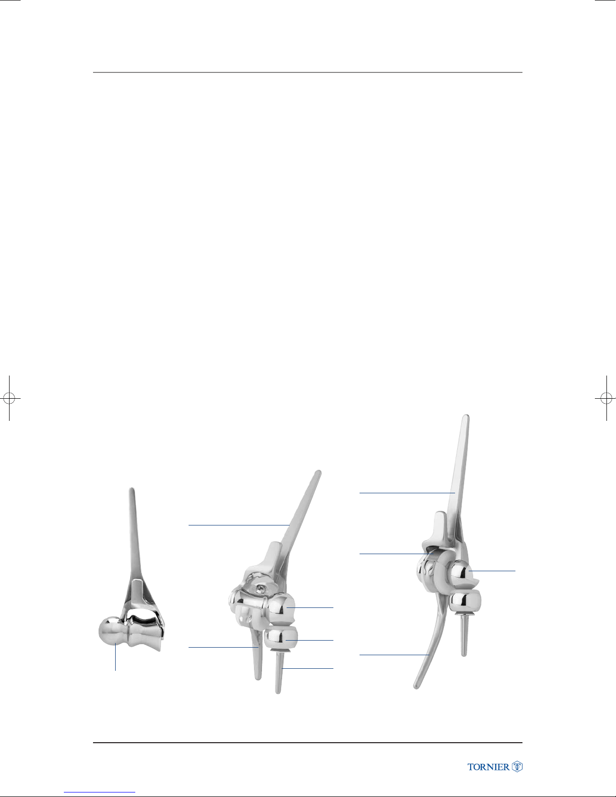
The Latitude®Elbow is the first 3rd generation elbow prosthesis. It features a true anatomical reconstruction
of the joint, modular components, and is adaptable to a wide range of indications.
®
The Latitude
kinematics of the elbow. Its unique instrumentation facilitates a step by step procedure that now makes
elbow arthroplasty accurate, precise and reproducible.
The Latitude
DESIGN GOALS
• Distinctive right and left anatomical components.
• Precision instrumentation.
• Intraoperative flexibility to utilize linked or unlinked.
• Accurate implant positioning referenced on the flexion-extension axis.
• Ease of assembly.
• Optimal bone preservation.
• Anatomic distribution of loads on polyethylene.
Elbow is designed to reproduce the patient’s anatomy; thus to restore the natural
®
Elbow offers maximum flexibility in elbow reconstruction.
CLINICAL OBJECTIVES
• Latitude for use in a wide range of indications.
• Latitude to reproduce patient flexion-extension axis.
• Total Latitude to use either unlinked or linked.
• Latitude to reconstruct the radio-humeral joint.
• Hemi Elbow Prosthesis.
Humeral stem
Short
ulnar stem
Anatomic
humeral spool
Humeral
spool
Radial
head
Radial
stem
Humeral stem
Ulnar cap
Standard
ulnar stem
Humeral
spool
Latitude Elbow Prosthesis
Latitude Elbow Prosthesis Surgical Technique UCLT101
unlinked configuration linked configuration anatomic configuration
3
Page 4
ANATOMICAL DESIGN
2. ANATOMICAL DESIGN VALIDATION
A comprehensive review of the literature, as well as a
morphological study on a large number of cadaver specimens,
was conducted. Osseous structures were digitized to obtain:
• Geometry of articular surfaces.
• Location of diaphyseal axis compared to these surfaces.
• Key parameters such as epicondyle diameter, condyle
and trochlear distance, offset and flexion-extension axis.
• Anatomical size.
STUDY RESULTS
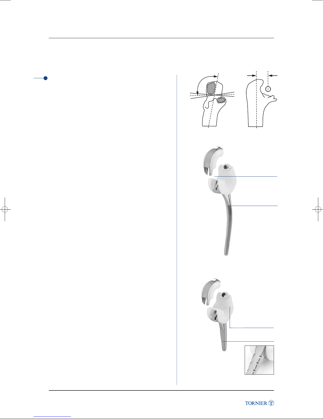
1 Humerus
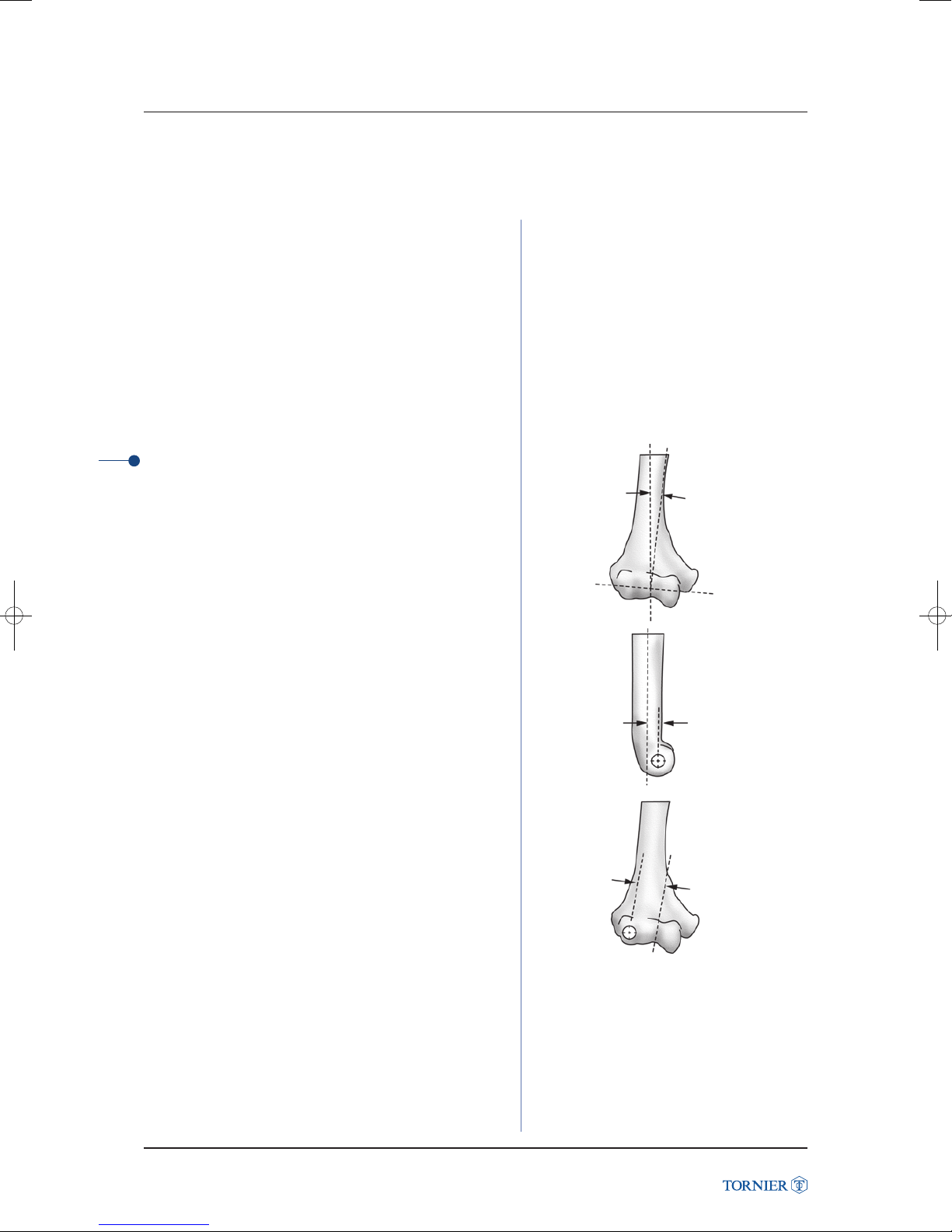
• The capitellum is spherical and the center axis of
the trochlea is aligned with the center of the capitellum.
The mean flexion axis is 6° of valgus (range 2° to 9°) (fig. 01).
Latitude Elbow Prosthesis
• The flexion-extension axis has a variable offset relative
to the axis of the diaphysis, varying between 4 and 8 mm
with a mean of 6 mm (fig. 02). This variability necessitates
a modular design with different articular offsets.
• There is a consistent relationship between the distance
from the center of the capitellum to the trochlear groove
and the diameter of the capitellum. The distance varies
from 15 mm
to 22.4 mm with a mean of 19 mm (fig. 03).
• The placement of the Latitude elbow is based on the normal
flexion-extension axis.
• 3 sizes of stem and 4 sizes of spool (small, medium, large,
large +).
• Different articular offsets (anterior, posterior and centered)
with respect to the humeral diaphysis.
6°
(fig. 01)
6mm
(fig. 02)
19 mm
(fig. 03)
Latitude Elbow Prosthesis Surgical Technique UCLT101
4
Page 5
2. ANATOMICAL DESIGN VALIDATION
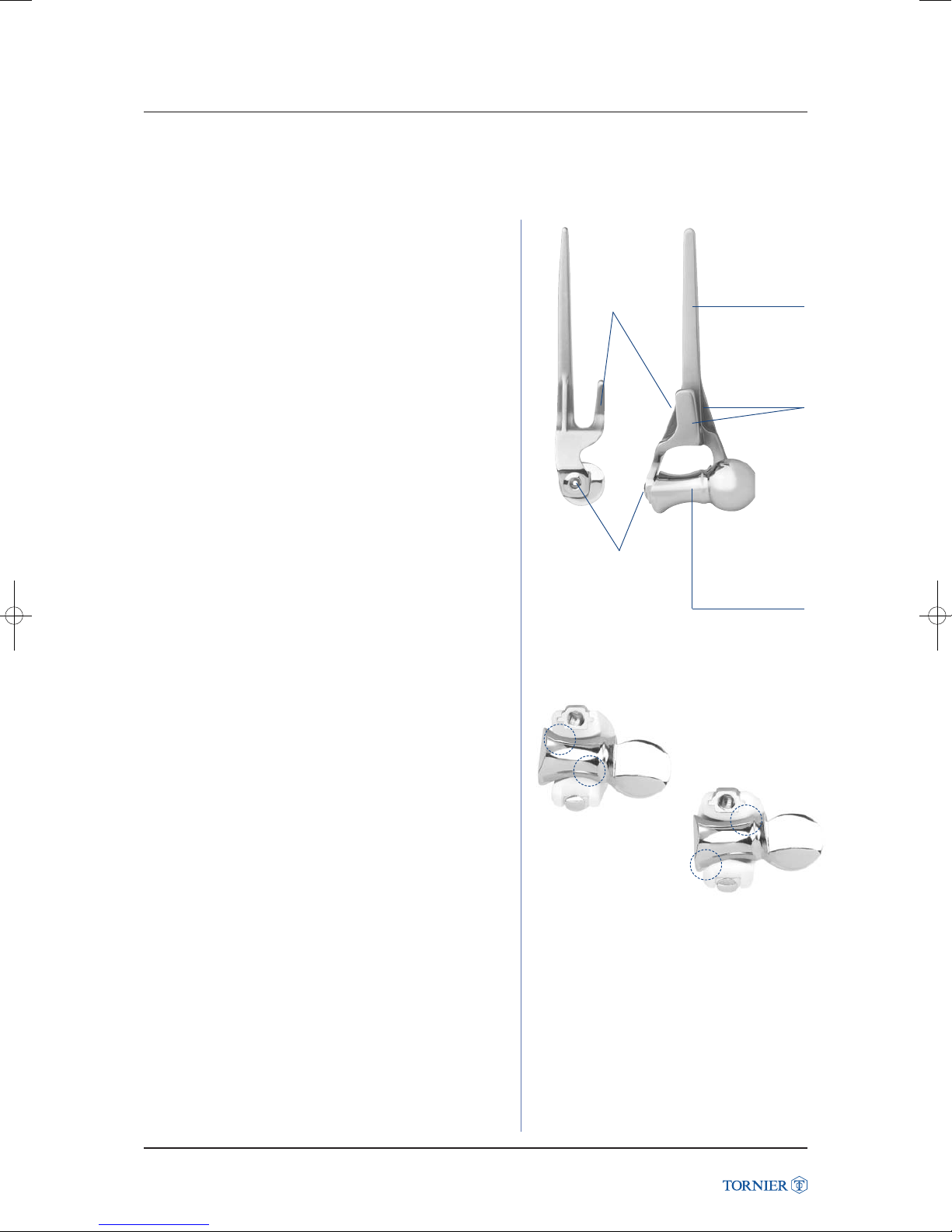
The humeral stem has medial and lateral fins to prevent
intramedullary rotation. The anterior flange accepts bone graft
to help prevent posterior migration. The posterior aspect of
the flange has a textured surface to enhance bone ongrowth
(fig. 04). The spool is secured to the stem with a cannulated
screw that allows for the passage of sutures to attach soft
tissues for initial stabilization.
(fig. 04)
Anterior flange
for bone graft
to prevent
posterior
migration
Stem in CoCr
for cemented use.
Square shape
for rotational
stability
Medial & lateral
fins to prevent
intramedullary
rotation
Humeral spools have been designed with a concave barrel
shaped trochlea to preserve linear contact throughout 7° of
valgus/varus movement with the ulnar component (fig. 05).
(fig. 05)
Cannulated
screw for suture
passage and
attachment
Circular concavity:
preserves linear
contact throughout
7° varus/valgus
movement
Latitude Elbow Prosthesis
Latitude Elbow Prosthesis Surgical Technique UCLT101
5
Page 6
ANATOMICAL DESIGN
2. ANATOMICAL DESIGN VALIDATION
15
2 Ulna
105°
• The morphology of the sigmoid facets provides congruent
surface contact around the flexion axis in full valgus.
The average position of the elbow flexion axis
is at 105° from the ulnar diaphyseal centerline (fig. 06).
• The flexion-extension axis is located between 12 mm
to 17 mm anterior to the diaphyseal axis with a mean
of 15 mm (fig. 07).
• The placement of the Latitude ulnar component is based
on the flexion-extension axis.
• 3 sizes of stems and 2 lengths
(standard and short figs 08 and 09).
• The Latitude ulnar stem is designed with an optional cap
so that the components can be unlinked or linked.
Latitude Elbow Prosthesis
The geometry of the standard stem has been designed
to replicate the natural bow of the ulna thus diminishing
stresses on the cortical wall. (fig. 08).
The polyethylene surfaces of the ulnar components have been
designed to facilitate an anatomic distribution of joint reactive
forces.
®
The Latitude
The decision to use the implant in a “linked” or “unlinked”
mode is made following the examination of the surrounding
soft tissues. The ulnar cap has been designed to capture
the humeral component to convert the implant to a linked
semi-constrained device.
Total Elbow offers intraoperative flexibility.
7°
(fig. 06)
(fig. 08) Standard ulnar stem
(fig. 07)
The unique fork
design allows for
ease of assembly
Anterior fin
to prevent
intramedullary
rotation
In the event that an unlinked construct was initially performed
and a linked revision is desired to correct instability,
a complete elbow revision is not required. The surgeon can
easily add the ulnar cap through a minimally invasive incision
transforming the prosthesis from unlinked to linked.
Latitude Elbow Prosthesis Surgical Technique UCLT101
Ideal polyethylene
thicknessconfiguration
for greater wear
properties
Notches on the stem
to improve cement fixation
(fig. 09) Short stem
6
Page 7
2. ANATOMICAL DESIGN VALIDATION
3 Radial head
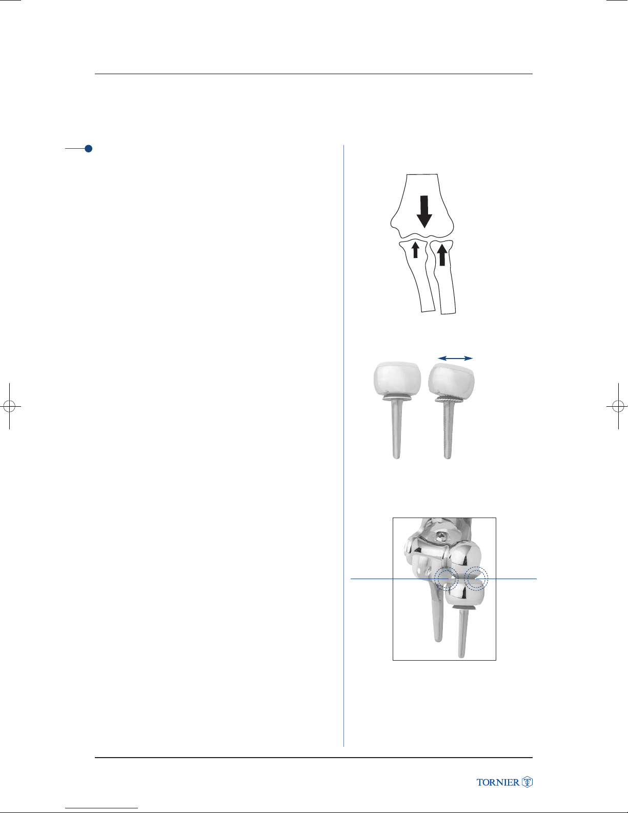
• The radial head is a key anatomical structure of the elbow.
Sixty percent of compressive loads are transferred across
the radio-humeral joint (fig. 10) Morrey et al, JBJS 70-A
1988.
• Without the radio-humeral joint, loading on the
ulno-humeral joint is increased contributing to the risk
of instability and premature wear.
• The placement of the Latitude elbow radial component
is based on the flexion-extension axis.
• 4 sizes of heads (Ø 18, 20, 22 and 24 mm) and 2 stem
diameters (5.0 mm and 6.5 mm).
®
The Latitude
to maintain the radio-humeral joint when anatomical
alignment is adequate.
The radial component has been designed to replicate
the radio-ulnar articulation.
The radial component is a bipolar design with +/- 10°
of motion to balance load transfer (fig. 11).
Elbow radial component enables the surgeon
100 %
40 %
60 %
(fig. 10)
+/- 10°
Latitude Elbow Prosthesis
(fig. 11)
The cobalt chrome ring of the radial head component
articulates with the polyethylene of the ulnar component
(fig. 12).
Latitude Elbow Prosthesis Surgical Technique UCLT101
Radioulnar
contact
Radio-
humeral
contact
(fig. 12)
7
Page 8
PRECISION INSTRUM
3. PRECISION INSTRUMENTATION
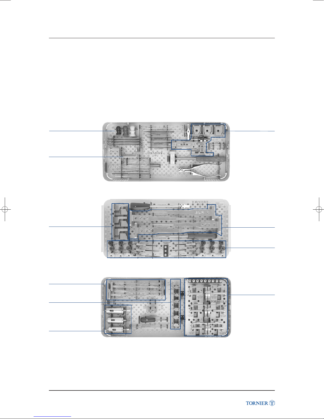
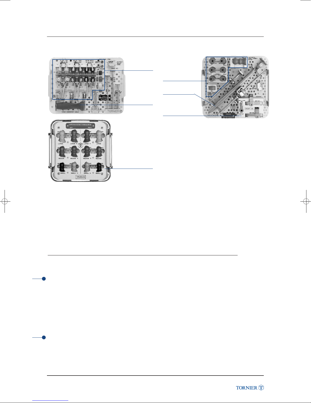
The Latitude®Elbow instruments bring precision and reproducibility to elbow arthroplasty in the setting
where there has been some preservation of normal anatomy.
The instruments are designed to offer a reproducible step-by-step procedure. Each jig uses anatomic landmarks
to insure replication of the natural anatomy. The flexion-extension axis is easily determined. The humeral, radial
and ulnar surgical steps are based on this reference point.
Anatomical spools
Flexion-extention
axis drilling guide
Latitude Elbow Prosthesis
Capitellum cutting guides
Ulnar rasps
Trochlear cutting guides
Humeral rasps
Humeral trial
components
Ulnar diaphysis
drill guides
Bell saws
Latitude Elbow Prosthesis Surgical Technique UCLT101
Ulnar cutting guides
8
Page 9
3. PRECISION INSTRUMENTATION
and radial
components
screwdriver
Anatomic spool
trial components
Ulnar
trial
Torque
Large +
components
Crimper
Triceps
on guides
INDICATIONS AND
CONTRAINDICATIONS
4. INDICATIONS AND CONTRAINDICATIONS
1 Indications for use
• Primary or secondary osteoarthritis and rheumatoid arthritis
• Correction of functional deformities
• Revision procedures where other treatments or devices have failed
• Treatment or fractures that are unmanageable using other techniques
• Same indications for Latitude Anatomic (Hemi Elbow Prosthesis)
• The prosthesis is for cemented use only
2 Contraindications
Latitude Elbow Prosthesis
Refer to the instruction for use delivered with the implant.
Latitude Elbow Prosthesis Surgical Technique UCLT101
9
Page 10
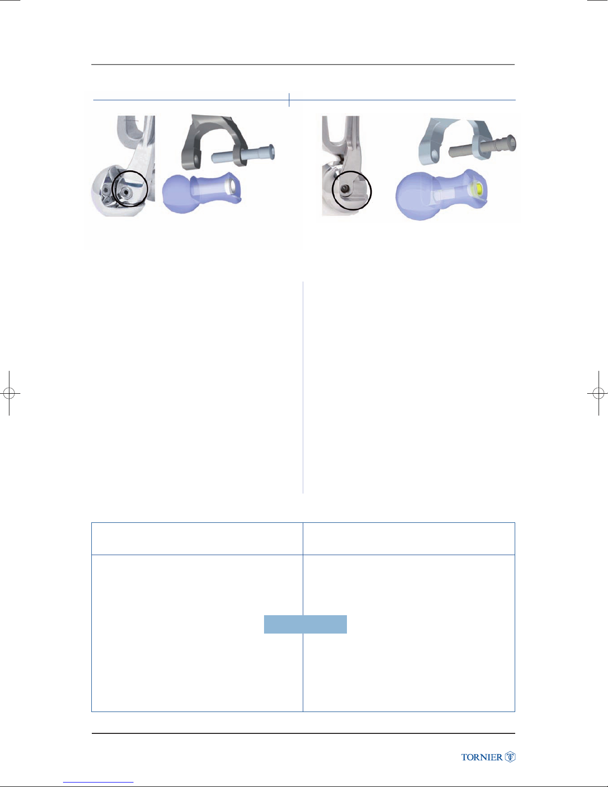
2007
W
Addendum
,ATITUDE
s4HEASSEMBLYBETWEENTHE,ATITUDESTEMAND
SPOOLHASBEENENHANCEDIN!SACONSEQUENCE
,ATITUDEND'ENERATIONSPOOLSAREINCOMPATIBLEWITH
,ATITUDEST'ENERATIONSTEMS
s(OWEVERTHENDGENERATIONHUMERALCOMPONENTS
STEMANDSPOOLARECOMPATIBLEWITHTHERESTOFTHE
CURRENTCOMPONENTSEGULNARSTEMSULNACAPSRADIAL
HEADSRADIALSTEMS
ST
'ENERATION ,ATITUDEND'ENERATION
st
Thus, should a Latitude 1
generation humeral
component be necessary :
- full revision of the humeral components (stem,
spool, screw) with Latitude 2
nd
generation
humeral components is recommended,
- The spool and screw revision only is still
possible. In that instance, please contact the
Custom Products Department 6 weeks before
surgery.
Département des produits spéciaux
TORNIER
161, rue Lavoisier
Montbonnot
38334 Saint Ismier Cedex – France
Tél : +33 (0)4 76 61 35 00
Fax : +33 (0)4 76 61 35 33
,ATITUDEST'ENERATION
NOTAVAILABLEANYMORE
(UMERALSTEM
$+9TO$+9
$+9TO$+9
(UMERALSCREW
$+9TO$+9
Latitude Elbow Prosthesis Surgical Technique UCLT101
Incompatibility
10
,ATITUDEND'ENERATION
3POOL
$+9TO$+9
$+9TO$+9
$+9TO$+9
!NATOMICSPOOL
$+9TO$+9
$+9TO$+9
Page 11
LATITUDE ANATOMIC
SURGITAL TECHNIQUE
5. LATITUDE ANATOMIC SURGICAL TECHNIQUE (Hemi Elbow Prosthesis)
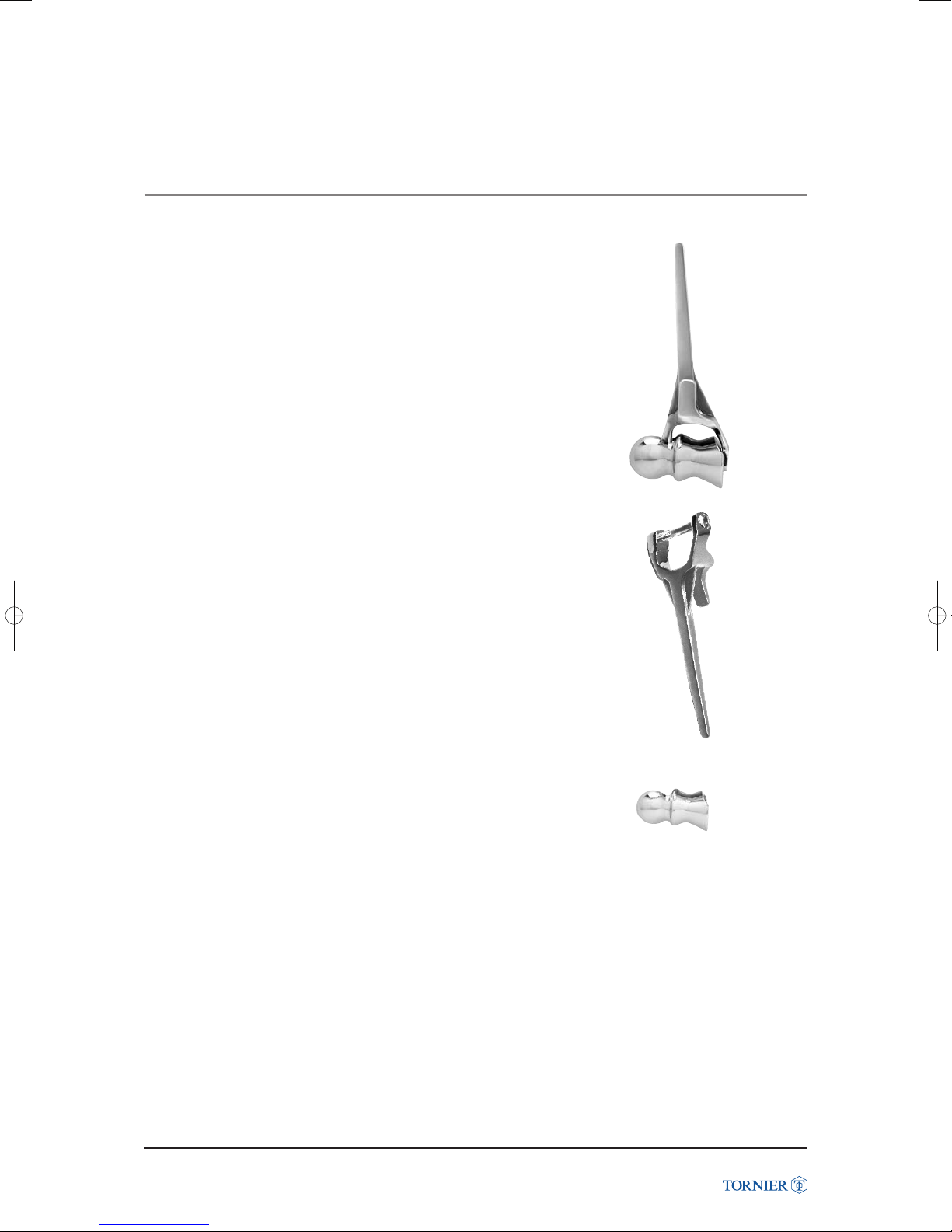
• Refer to pages 11 to 22 for the Latitude Anatomic
surgical technique (fig. 13).
Note
The Latitude Anatomic Prosthesis does not take spool
offset into consideration.
• Refer to page 33 for the cement and bone graft technique
• Refer to page 36 for the suture technique and closure.
(fig. 13)
Note
The Latitude Anatomic Prosthesis components are:
• Humeral stem (the one used for Total Elbow Prosthesis)
DKY181 to DKY186 (fig. 14).
• Anatomic spool (different than the one used for the Total
Elbow Prosthesis) (fig. 15):
- DKY161 to DKY166
- DKY171 to DKY176.
Latitude Elbow Prosthesis
(fig. 14)
(fig. 15)
Latitude Elbow Prosthesis Surgical Technique UCLT101
11
Page 12
EXPOSURE
6. EXPOSURE
Patient position
The patient may be positioned in a lateral decubitus position
or a supine position based upon surgeon preference.
It is important to have full mobility of the elbow
during the procedure. A sterile tourniquet is employed.
Incision
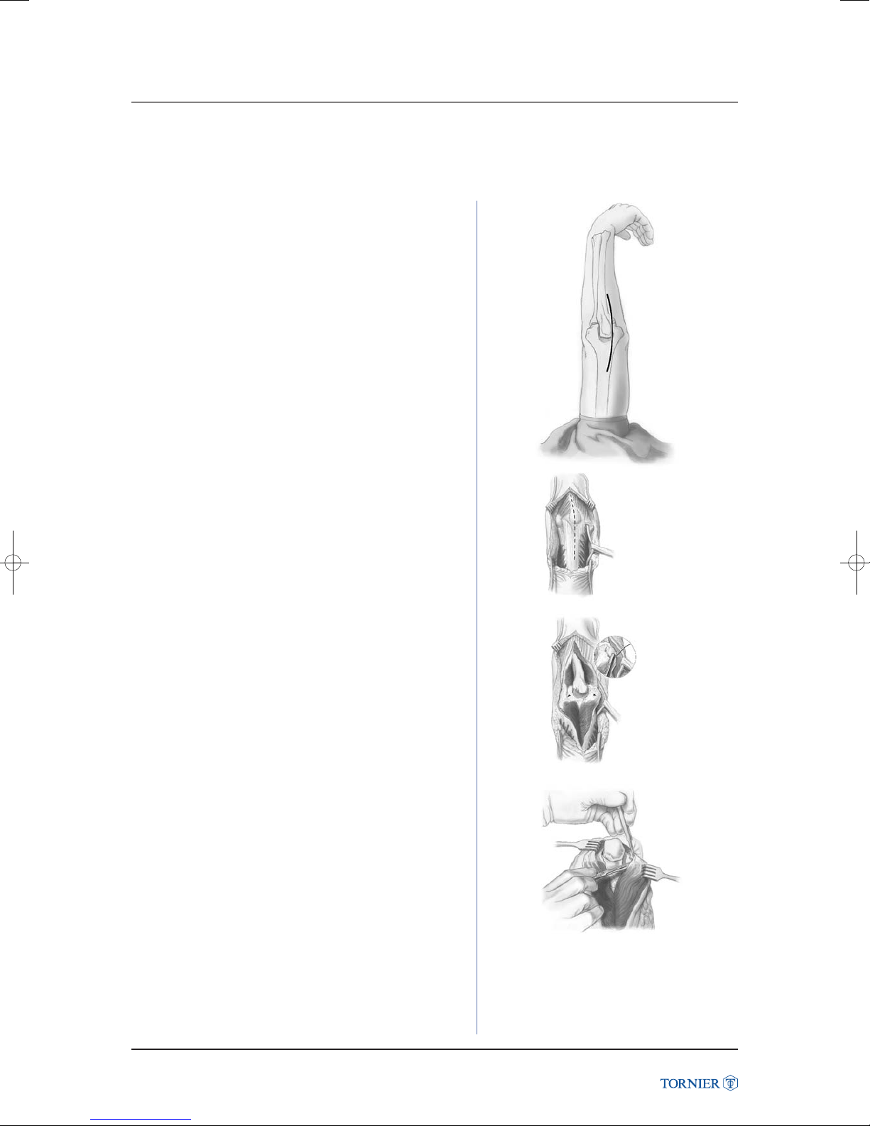
A straight incision is made approximately 15 centimeters
in length and centered just lateral to the medial epicondyle
and just medial to the tip of the olecranon (fig. 16a).
(fig. 16a)
Full thickness medial and lateral flaps are elevated
on the deep fascia (fig. 16b).
Latitude Elbow Prosthesis
Ulnar Nerve transposition
The medial aspect of the triceps mechanism is identified
and the ulnar nerve is isolated using loupe magnification
(fig. 16c). The medial intermuscular septum is excised.
The ulnar nerve is mobilized and transposed anteriorly
into the subcutaneous tissue (fig. 16d).
It is carefully protected throughout the remainder of the
procedure.
(fig. 16b)
(fig. 16c)
(fig. 16d)
Latitude Elbow Prosthesis Surgical Technique UCLT101
12
Page 13
EXPOSURE
6. EXPOSURE
Triceps Management
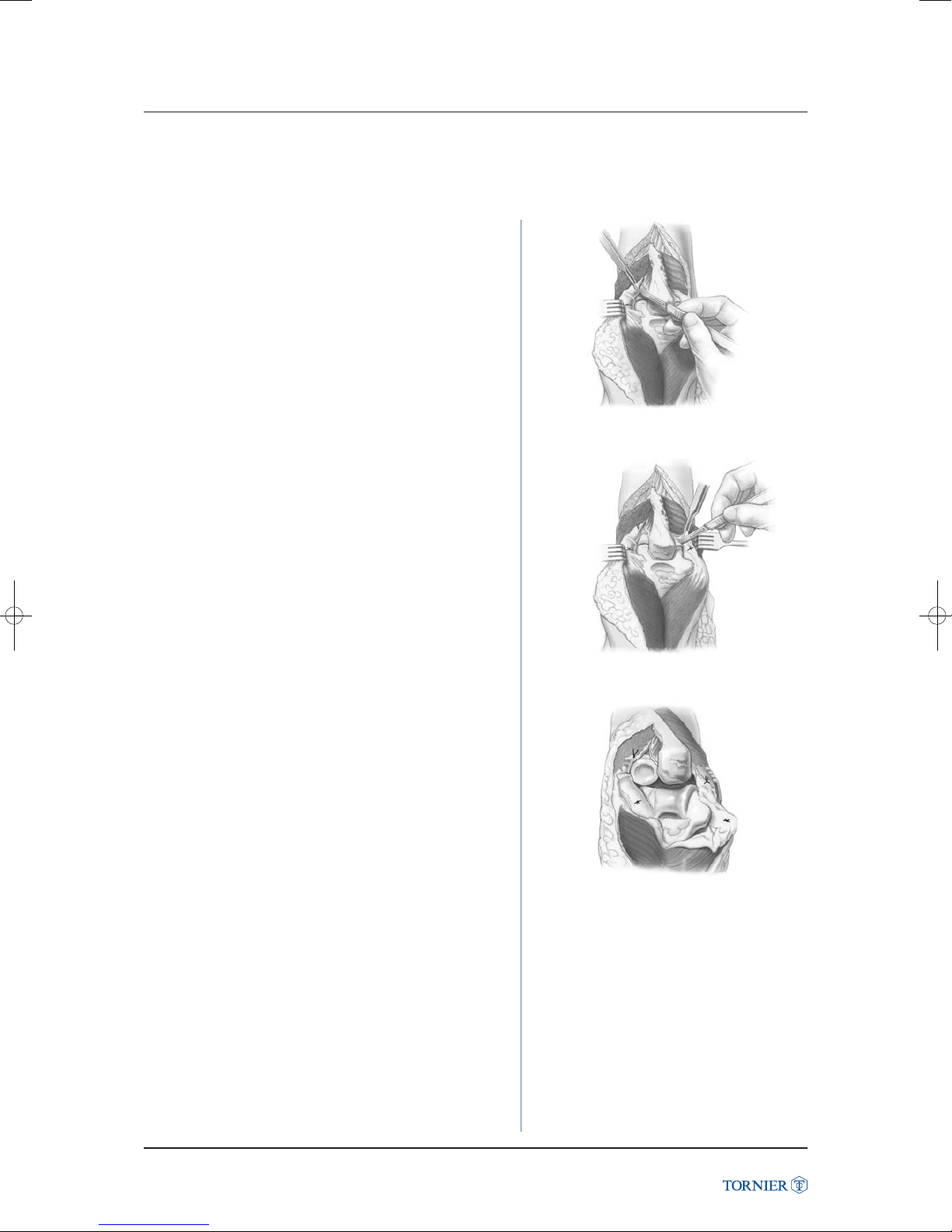
Management of the triceps mechanism is at the surgeons
discretion.
Common procedures include splitting the triceps centrally,
elevating it from medial to lateral, or from lateral to medial.
The triceps attachment to the ulna is released by dividing
Sharpey’s fibers.
Alternative approaches include dividing the triceps tendon
proximal to the olecranon. The continuity of the triceps tendon
can be maintained when the distal humerus is bone deficient
using a triceps sparing approach.
(fig. 16e)
Triceps splitting approach
The triceps tendon is split centrally ascending 8 cm proximal
from the tip of the olecranon.
The tendon is then reflected medially and laterally
off the olecranon by dividing Sharpey’s fibers.
The medial and lateral portions of the tendon are kept
in continuity with the flexor carpi ulnaris and anconeus
respectively. The humeral attachments of the medial
and lateral collateral ligaments and their overlying flexor
and extensor muscle origins are sharply divided off the medial
and lateral epicondyles to facilitate joint subluxation.
The ligament origins are marked with a colored suture
to facilitate subsequent reattachment.
Latitude Elbow Prosthesis
(fig. 16f)
(fig. 16g)
Latitude Elbow Prosthesis Surgical Technique UCLT101
13
Page 14
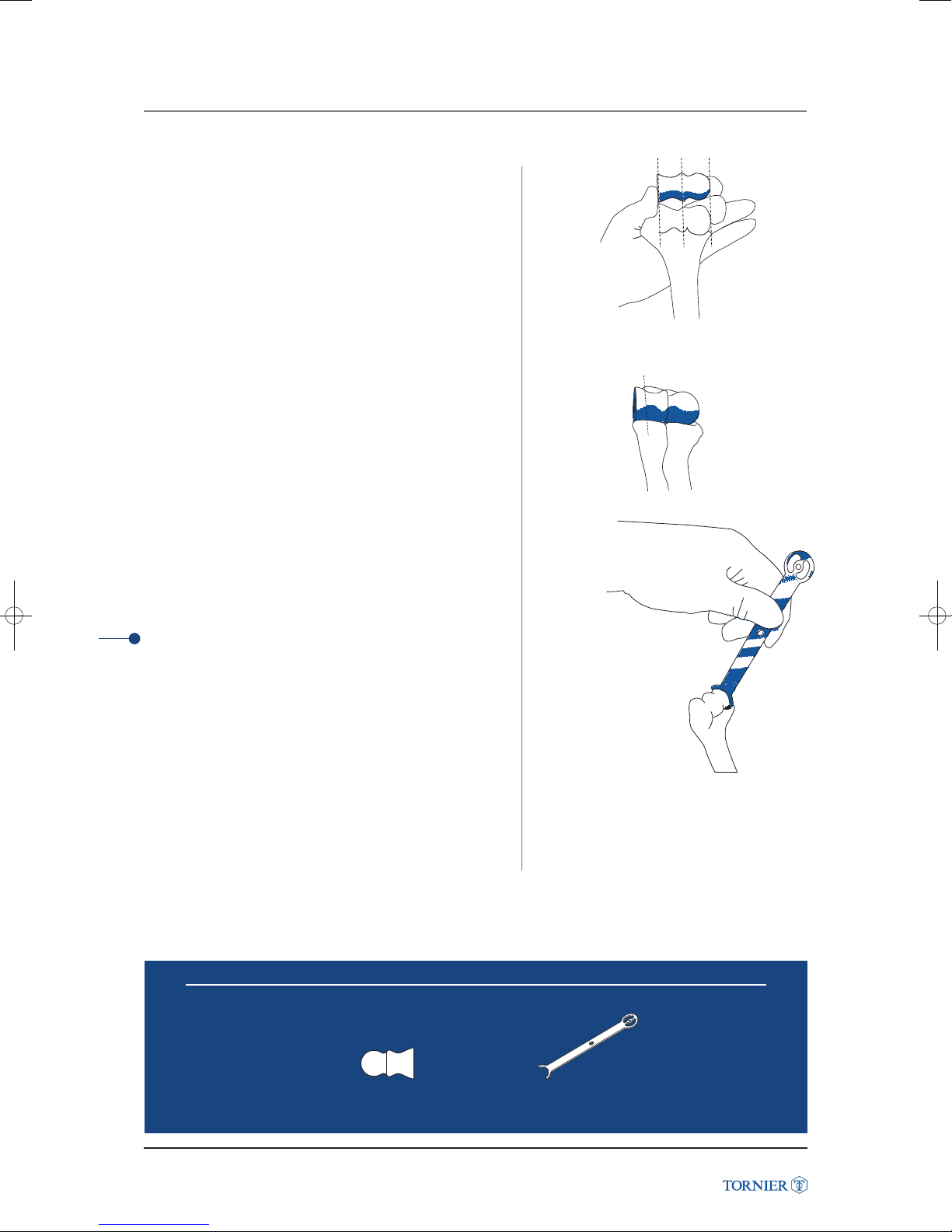
HUMERAL PREPARA
7. HUMERAL PREPARATION
Size the humeral condyle with colored anatomical spools
and gauges (small, medium, large, large +).
• Start by comparing the anatomical spool to the patient’s
capitellum (fig. 17a).
(fig. 17a) Anterior view
• Then verify that the spool fits exactly into the ulna
and is perfectly aligned with the radial head (fig. 17b).
(fig. 17b)
• The size of the capitellum may be confirmed with the gauge
(fig. 17c).
Choose the final implant size based on these measurements.
Latitude Elbow Prosthesis
This determination will be used throughout the procedure.
TIP
Should the patient’s humeral condyle size fall between
two anatomical sized trial spools, pick the smaller one
for the remainder of the procedure.
Instruments to use
(fig. 17c)
Latitude Elbow Prosthesis Surgical Technique UCLT101
Anatomical spool
Capitellum radii gauge
14
Page 15
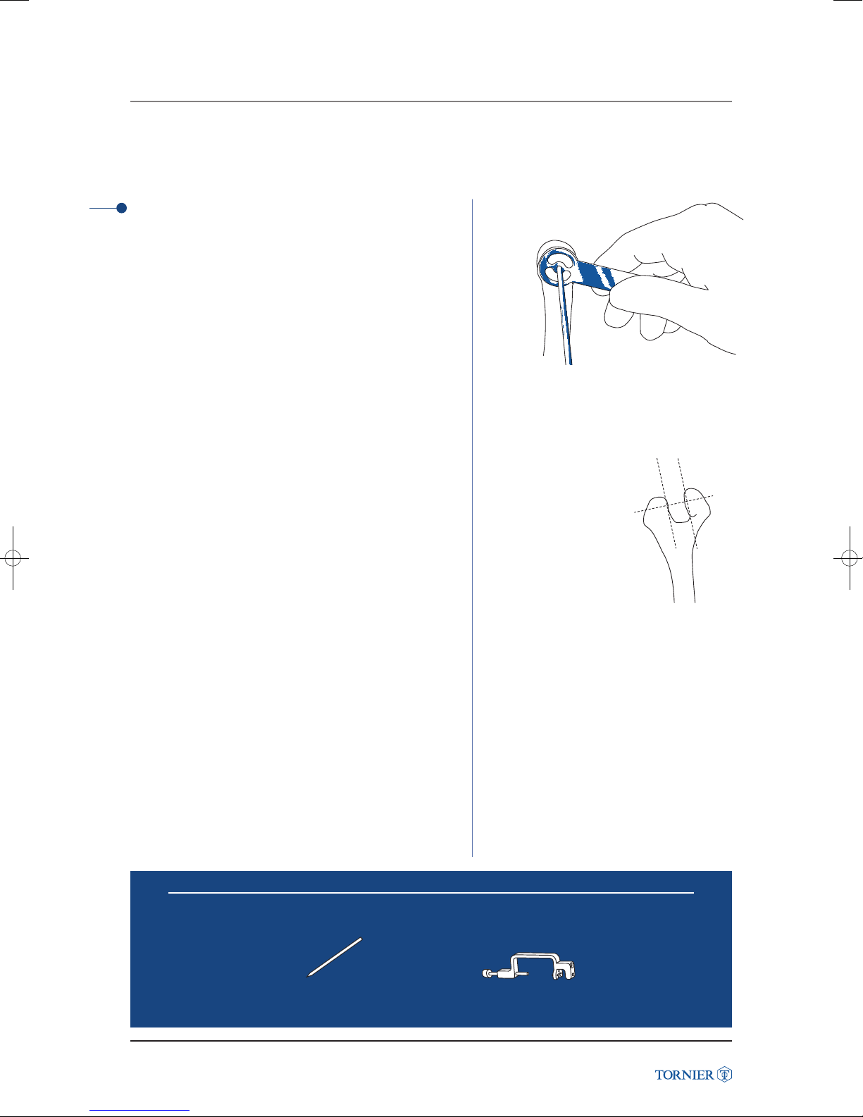
7. HUMERAL PREPARATION
1 Flexion-extension axis determination
Mark the center of the flexion-extension axis on the
capitellum side with the capitellum radii gauge with the 3 mm
self-drilling pin to reference the proper position of the drilling
guide on the flexion-extension axis (fig. 18).
The location of the axis is typically at the site of attachment
of the lateral ligaments to the lateral epicondyle.
If the capitellum is imagined to be a circle when viewed
from the lateral side, the flexion-extension axis is located
at the center point of this circle.
The circular gauge is a useful tool to visually estimate
this location.
Note
The key to a successful outcome is the accurate determination
of the flexion-extension axis.
(fig. 18) Lateral view
Remove the central portion of the distal humerus
(trochlea, sulcus and lateral ridge) to the proximal aspect
of the olecranon fossa with either an oscillating saw or large
rongeur (fig. 19).
Instruments to use
Latitude Elbow Prosthesis
(fig. 19)
Latitude Elbow Prosthesis Surgical Technique UCLT101
Stabilization pin
Drilling guide
15
Page 16
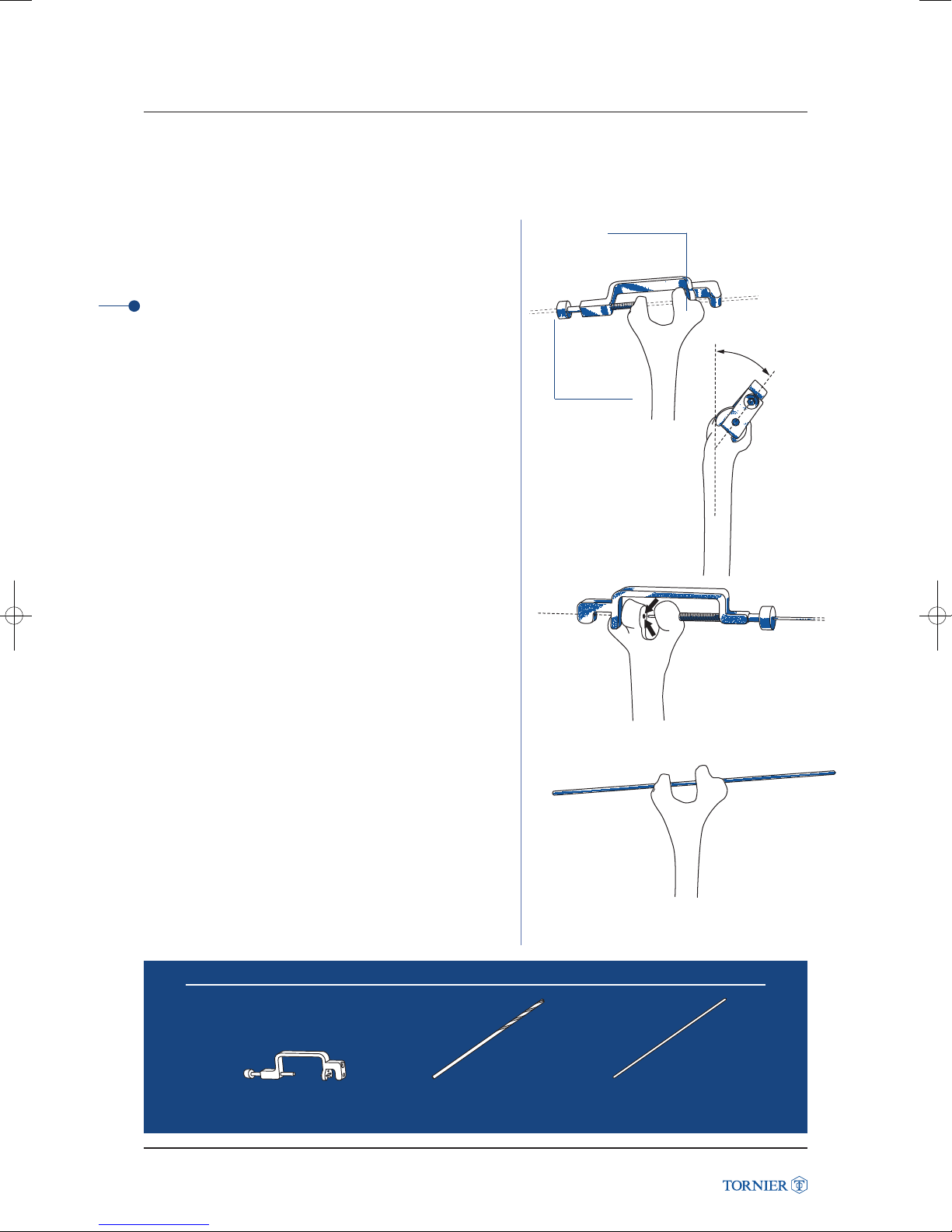
HUMERAL PREPARA
7. HUMERAL PREPARATION
Position the flexion-extension axis drill guide on the distal
humerus. It should sit with an approximate angle of 45°
anteriorly (fig. 20a & 20b).
TIP
The assembled drill guide should appear to be pointed
approximately 45° anterior to the coronal plane. (fig. 20b).
The cannulated screw should be placed over the drill hole
previously marked on the capitellum.
The medial notch of the guide assembly is placed on
the anterior and inferior portion of the medial epicondyle
at approximately 45° anteriorly.
The center of the medial notch should be roughly at the center
of the medial ridge of the trochlea such that an axis pin would
appear to exit at the anterior and inferior edge of the medial
epicondyle’s intersection with the trochlea (fig. 20a).
Latitude Elbow Prosthesis
Drill the flexion-extension axis and then remove the guide
(fig. 20c).
Medial epicondyle
45°
Cannulated screw
(fig. 20a) Posterior view
(fig. 20b) Medial view
As a check, reinsert the flexion-extension pin to confirm
correct alignment (fig. 21).
Instruments to use
Drilling guide
Latitude Elbow Prosthesis Surgical Technique UCLT101
Drill bit
16
(fig. 20c) Anterior view
(fig. 21) Posterior view
Axis pin
Page 17
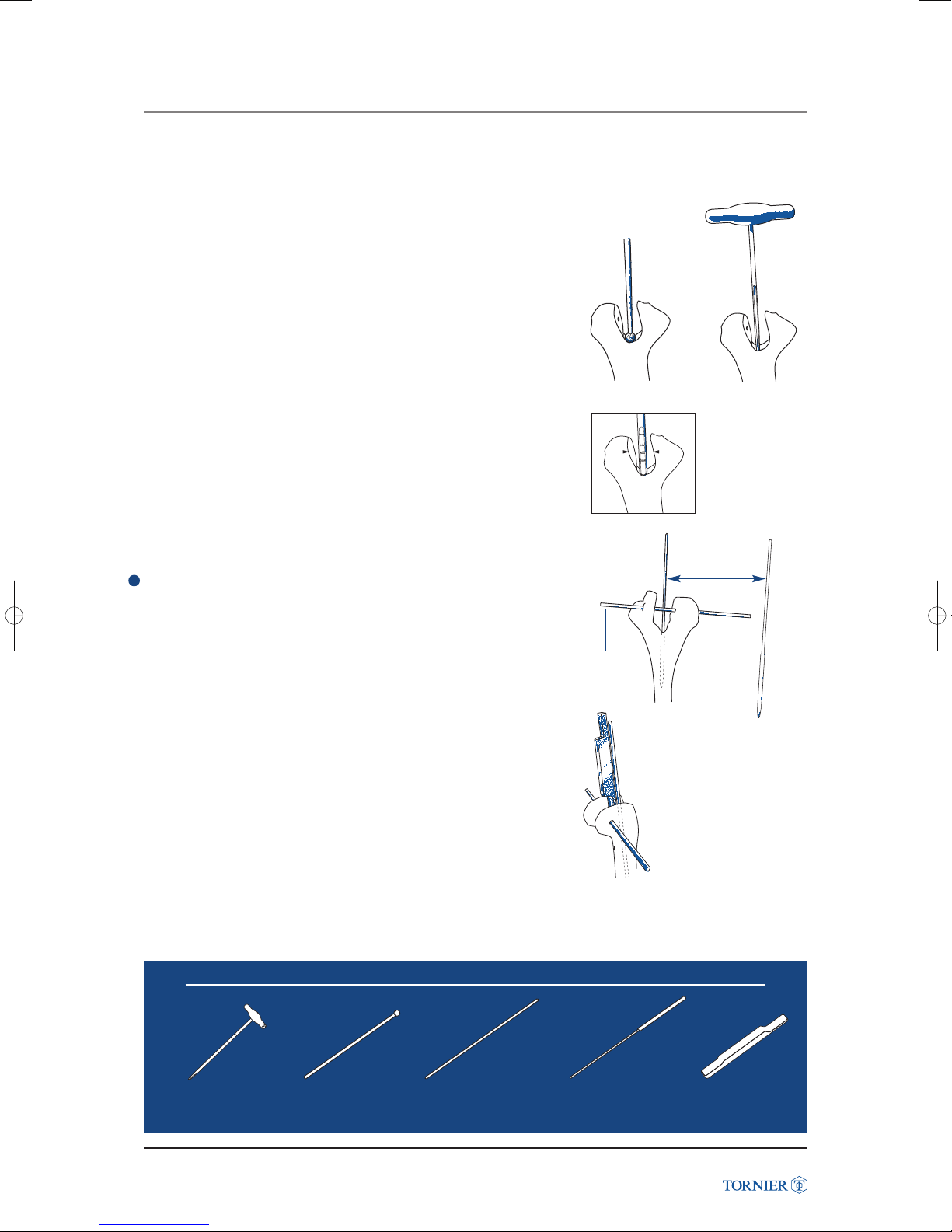
7. HUMERAL PREPARATION
Open the medullary canal with a high speed burr (fig. 22a).
After burring, use the T-handle reamer to shape the medullary
canal (fig. 22b).
The T-handle reamer should be inserted up to the intersection
of the predetermined implant size marked on the shaft
and the flexion-extension axis (fig. 23).
2 Humeral Offset Determination
Insert the pointed intramedullary alignment rod into the shaft
of the humerus.
Anterior to the rod, insert the flexion-extension axis pin
through the previously drilled holes (fig. 24a).
Select the offset gauge of the previously determined humeral
size (small, medium, large). Determine spool offset by placing
offset gauge between the flexion-extension axis pin
and the intramedullary alignment rod (fig. 24b).
(fig. 22a)
(fig. 23)
Flexionextension
axis pin
(fig. 24a)
(fig. 24b)
(fig. 22b)
Medullary
alignment rod
Latitude Elbow Prosthesis
Humeral diaphysis reamer
Latitude Elbow Prosthesis Surgical Technique UCLT101
Burr
Instruments to use
Flexion/extension
axis pin
17
Medullary
alignment rod
Offset determining gauge
Page 18
HUMERAL PREPARA
7. HUMERAL PREPARATION
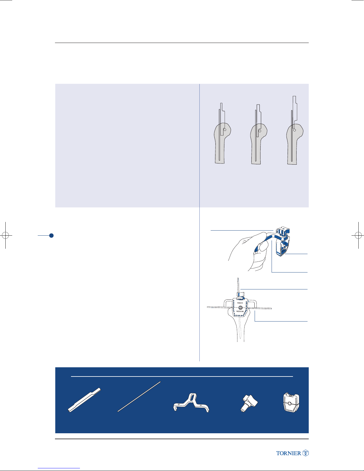
Using and interpreting the offset gauge
Starting with the thickest portion of the offset gauge,
slide it along the intramedullary alignment rod.
If this portion can be inserted in between the
flexion-extension axis pin and the alignment rod, then
the offset is ANTERIOR (fig. I).
If the thickest portion cannot be inserted, rotate
the gauge and try inserting the thinnest portion of
the gauge. If it fits in between the axis and the
alignment rod, then the offset is CENTERED (fig. II).
If the thinnest portion of the gauge cannot be inserted,
then the offset is POSTERIOR (fig. III).
(fig. I)
Anterior
offset
(fig. II) (fig. III)
Centered
offset
Posterior
offset
Latitude Elbow Prosthesis
3 Humeral Distal Preparation
Assemble the appropriate size humeral trochlea cutting block
to the trochlear cutting guide support with the assembly
screw. Do not fully tighten the assembly screw at this time
(fig. 25a).
Position the cutting guide on the flexion-extension axis pin
and align with the medullary alignment rodas shown (fig. 25b).
Instruments to use
Assembly screw
(fig. 25a)
(fig. 25b)
Humeral
trochlea
cutting
block
Trochlear cutting
guide support
Medullary
alignment rod
Flexion-extension
axis pin
Offset determining gauge
Latitude Elbow Prosthesis Surgical Technique UCLT101
Flexion/extension
axis pin
Humeral trochlea
cutting guide support
18
Assembly screw
Humeral trochlea
cutting block
Page 19
7. HUMERAL PREPARATION
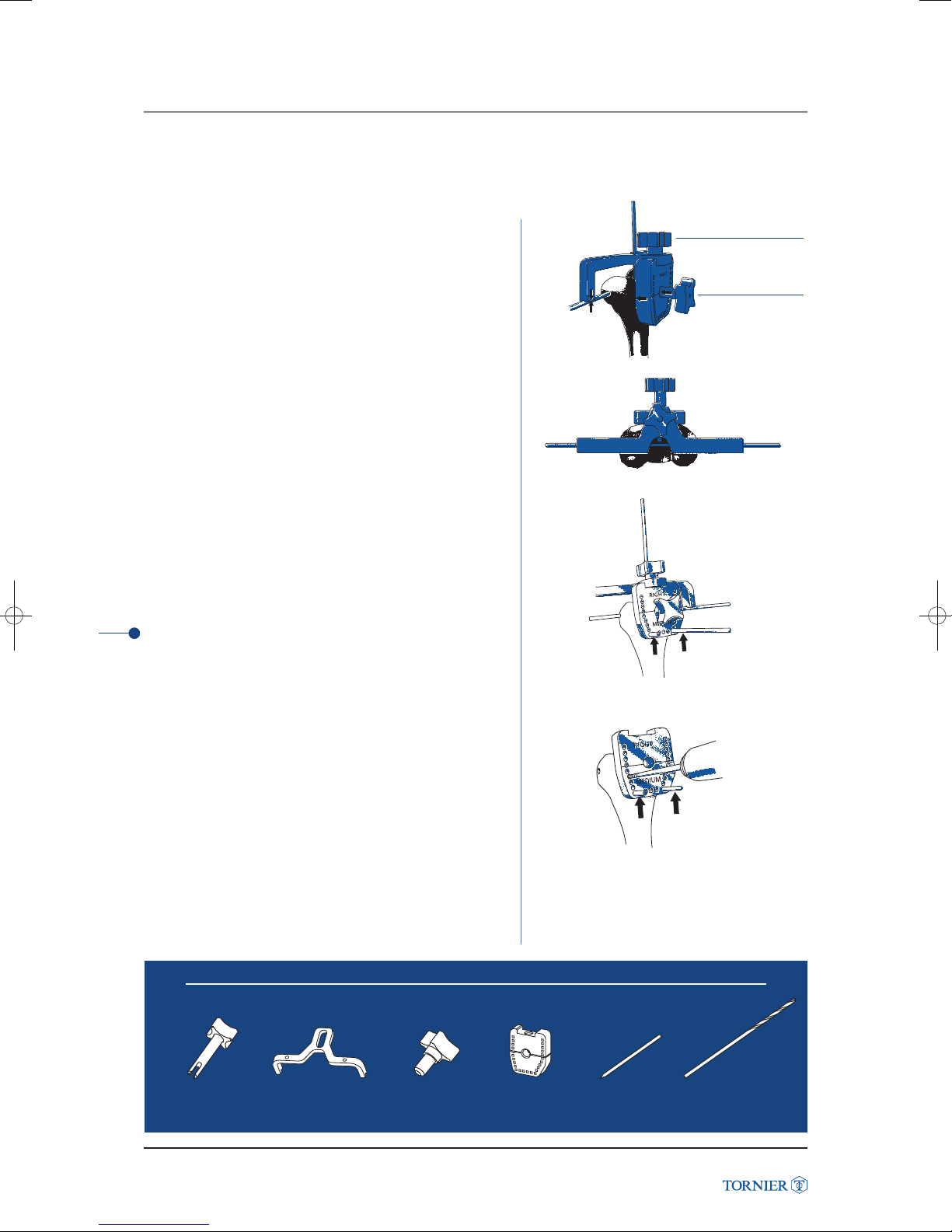
Adjust the cutting guide by sliding the distal humeral cutting
block to make firm contact with the posterior humerus
and then firmly tighten the assembly screw (fig. 26c).
Medial-lateral placement of the humeral trochlea cutting block
is completed by inserting the diaphysis aiming guide through
the block and engaging it onto the medullary alignment rod.
Using the 3 mm diameter drill bit, drill 2 holes at the inferior
portion of the humeral trochlea cutting block and place
2 stabilizing pins as shown (fig. 27).
TIP
Size and side designations on all instruments always face
the surgeon.
(fig. 26c)
(fig. 27)
Stabilizing pins
Assembly
screw
Diaphysis
aiming guide
Latitude Elbow Prosthesis
Remove the cutting support, the flexion-extension axis pin
and the intramedullary alignment rod. Drill with the 3 mm drill
bit through the remaining holes on the cutting block as shown
(fig. 28). Take care to avoid damaging anterior structures.
Diaphysis aiming guide
Latitude Elbow Prosthesis Surgical Technique UCLT101
Humeral trochlea
cutting guide support
Instruments to use
Assembly screw
Humeral trochlea
19
(fig. 28)
cutting block
Stabilization pin
Drill bit
Page 20
HUMERAL PREPARA
7. HUMERAL PREPARATION
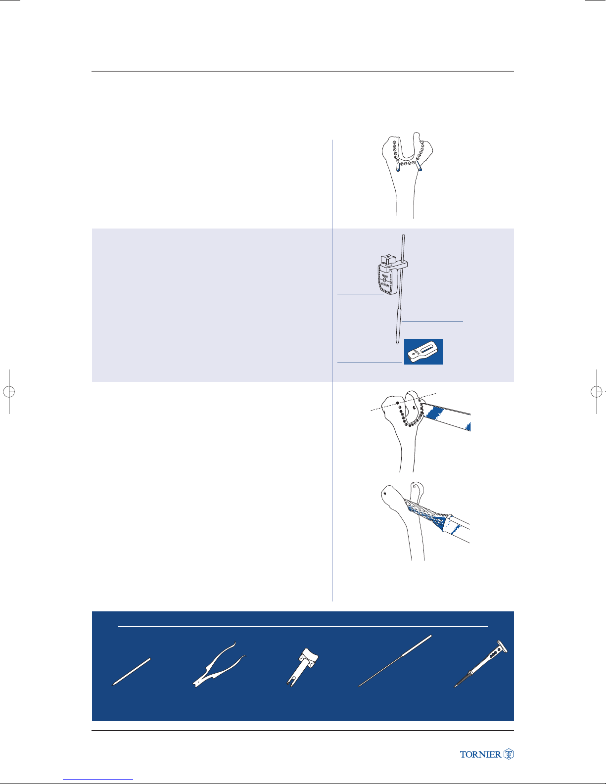
Slide the cutting block off the stabilizing pins and remove
them with the pin puller (fig. 29).
(fig. 29)
Lack of anatomical landmark
In the absence of anatomical landmarks on the trochlea,
use the modified humeral cutting guide.
Assemble the cutting block to the “No trochlea” support
noting either right or left with the assembly screw.
Slide the completed assembly over the medullary
alignement rod until the flexion/extension line figured
on the block is correctly positioned.
Latitude Elbow Prosthesis
Remove the bony bridge between the drill holes with
a straight osteotome, microsaggital saw or rongeur
as necessary (fig. 30).
If the medial trochlea has been excised, mark where
the flexion-extension axis was, using a marking pen.
Smooth the cut surface with a humeral broach or burr (fig. 31).
Humeral
cutting
block
“No trochlea”
support guide
(fig. 30)
Medullary
alignment rod
Stabilization pin
Latitude Elbow Prosthesis Surgical Technique UCLT101
Pin puller
Instruments to use
Diaphysis
aiming guide
20
(fig. 31)
Medullary
alignment rod
Humeral diaphysis
canal broach
Page 21
7. HUMERAL PREPARATION
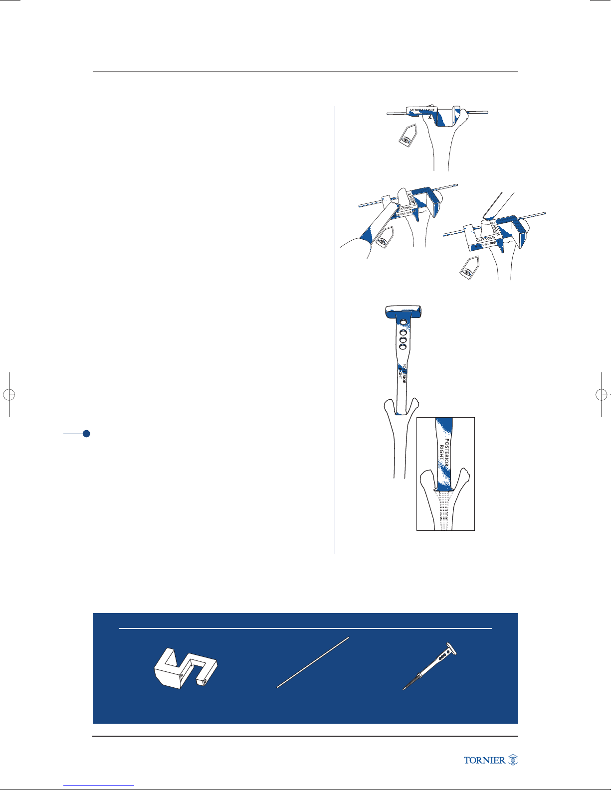
Using the correct size and side capitellum
cutting guide, position it in the trochlear cut
as shown (fig. 32).
Insert the flexion-extension axis pin through both the axis
and the cutting guide to stabilize and align the jig. Make
distal and anterior capitellar cuts with an oscillating saw
on the marked surface as shown (fig. 33).
Broach the humeral canal with the starting broach
and then proceed sequentially to the selected size
of the humeral component (fig. 34a).
(fig. 32) Posterior view
(fig. 33)
TIP
The indication of side right or left should point posteriorly
so that it can be read by the surgeon (fig. 34b).
Instruments to use
Latitude Elbow Prosthesis
(fig. 34a)
(fig. 34b)
Capitellum cutting guide
Latitude Elbow Prosthesis Surgical Technique UCLT101
Flexion/extension
axis pin
21
Humeral diaphysis
canal broach
Page 22
LEFT
LARGE
ASSEMBLY
1
ASSEMBLY: HUMERAL
TRIAL STEM
7. HUMERAL TRIAL STEM
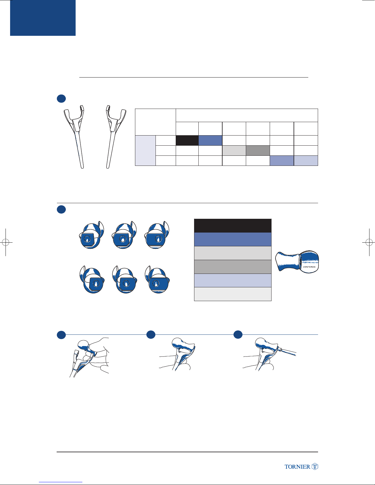
Select the appropriate size humeral trial stem either right or left (fig. 35).
SPOOL - TOTAL ELBOW PROSTHESIS &LATITUDE ANATOMIC
(fig. 35)
SMALL
SMALL
rightleft
HUMERAL
STEMS
MEDIUM
LARGE
SMALL PLUS
(Anatomic only)
MEDIUM
MEDIUM PLUS
(Anatomic only)
LARGE LARGE PLUS
Select the corresponding spool (side, size and offset) according to the following table (fig. 36).
2
Latitude Elbow Prosthesis
left
right
1
anterior
center
medial view
posterior
(fig. 36)
2
SMALL = BLACK
SMALL PLUS = GREY
(Anatomic only)
MEDIUM = RED
MEDIUM PLUS = BLUE
(Anatomic only)
LARGE = YELLOW
LARGE PLUS =
GREEN
3
LEFT
LARGE
Position the round part (capitellum) of the spool on the left for a left trial/on the right for a right trial stem.
Place the appropriate size trial humeral screw from medial to lateral. Tighten using the 4.5 mm hex screwdriver.
Latitude Elbow Prosthesis Surgical Technique UCLT101
22
Page 23
ASSEMBLY: HUMERAL
TRIAL STEM
7. HUMERAL TRIAL STEM
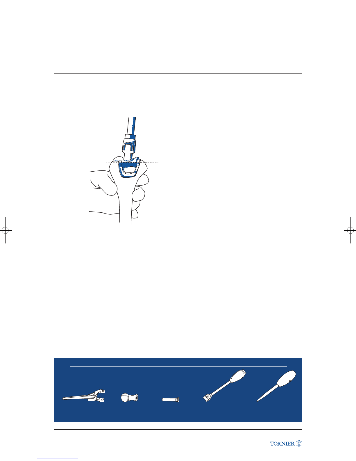
Position the trial stem assembly in the humeral shaft.
Use the impactor to seat the implant flush with the bone (fig. 37).
(fig. 37)
Instruments to use
Latitude Elbow Prosthesis
Trial humeral stem
Latitude Elbow Prosthesis Surgical Technique UCLT101
Trial spool
Trial humeral screw
23
Impactor
4.5 hexagonal screwdriver
Page 24
ASSEMBLY
Note
In cases where the triceps has been preserved, refer to page 37 for ulnar preparation with the triceps on jig.
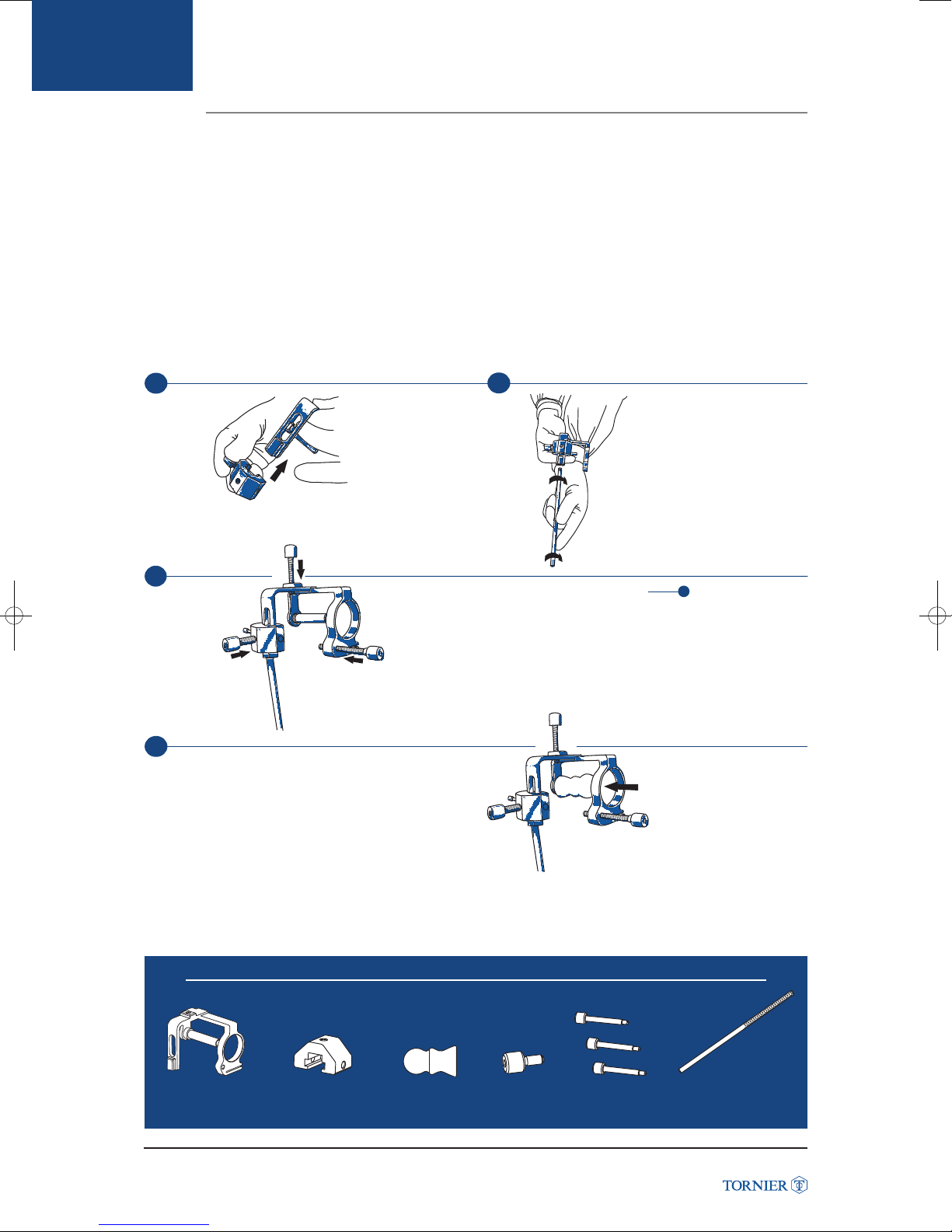
• Components required to assemble the ulnar cutting guide:
• Choose the appropriate size and side cutting guide.
• Assemble the cutting guide as shown (see assembled cutting guide fig. (38a-d)).
1
ASSEMBLY
8. RADIO-ULNAR CUTTING GUIDE
- Cutting guide. - Sliding block.
- Forearm axis guide. - 3 locking screws: flat/trochar/cannulated (Ø 2 mm).
2
Slide the block
onto the cutting
guide.
Screw the forearm
axis guide into the
cutting guide.
(fig. 38a)
3
Latitude Elbow Prosthesis
4
Insert the selected spool
on the cutting axis.
Screw the desired type
screws (cannulated,
trochar or flat) into the
cutting guide.
(fig. 38c)
(fig. 38b)
TIP: A flat screw
is preferred for the sliding
block to sit on the flat
spot of the ulna.
(fig. 38d)
Ulnar/radial cutting guide
Latitude Elbow Prosthesis Surgical Technique UCLT101
Ulnar/radial
cutting guide
sliding block
Instruments to use
Anatomical spool
24
Locking screw
Tightening screws
Forearm positioning guide
Page 25
ULNAR PREPARATION
8. ULNAR PREPARATION (triceps splitting approach)
1 Radio-Ulnar Cutting guide Positioning
Top screw
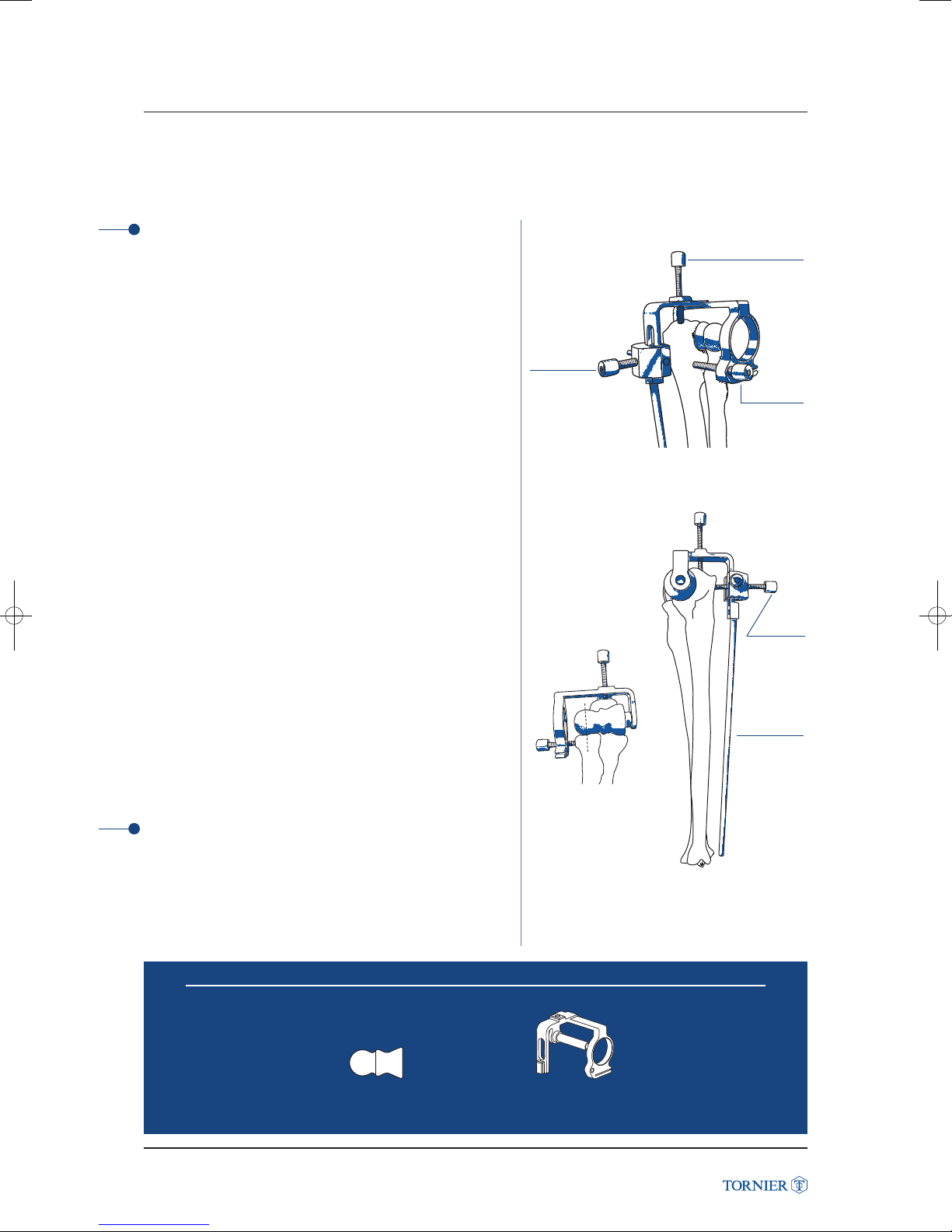
Position the cutting guide on the ulna and radial head (fig. 39).
The correct positioning of the guide is secured
with the three stabilizing screws.
Screws are positioned:
• on the proximal olecranon.
• on the flat posterior surface.
• on the lateral side of the ulna.
Tighten the 3 stabilizing screws with the 4.5 mm hex
screwdriver.
First, tighten the posterior screw on the flat spot of the ulna
to ensure that the spool will sit correctly in the sigmoid cavity
of the olecranon.
Then tighten the remaining two screws.
Make sure that the forearm axis guide points
towards the ulnar styloid (fig. 40a).
Make sure that the anatomical spool seats properly into
the ulna and is anatomically aligned with the radial head
(fig. 40b).
Posterior flat
spot screw
(fig. 39) Postero-lateral view
(fig. 40b) Anterior view
Lateral
screw
Posterior
screw
Forearm
axis guide
Latitude Elbow Prosthesis
TIP
The correct positioning of the jig is essential
to ensure proper radial head and ulnar resection.
Latitude Elbow Prosthesis Surgical Technique UCLT101
Anatomical spool
(fig. 40a) Medial view
Instruments to use
Ulnar/radial cutting guide
25
Page 26
ULNAR PREPARATIO
8. ULNAR PREPARATION (triceps splitting approach)
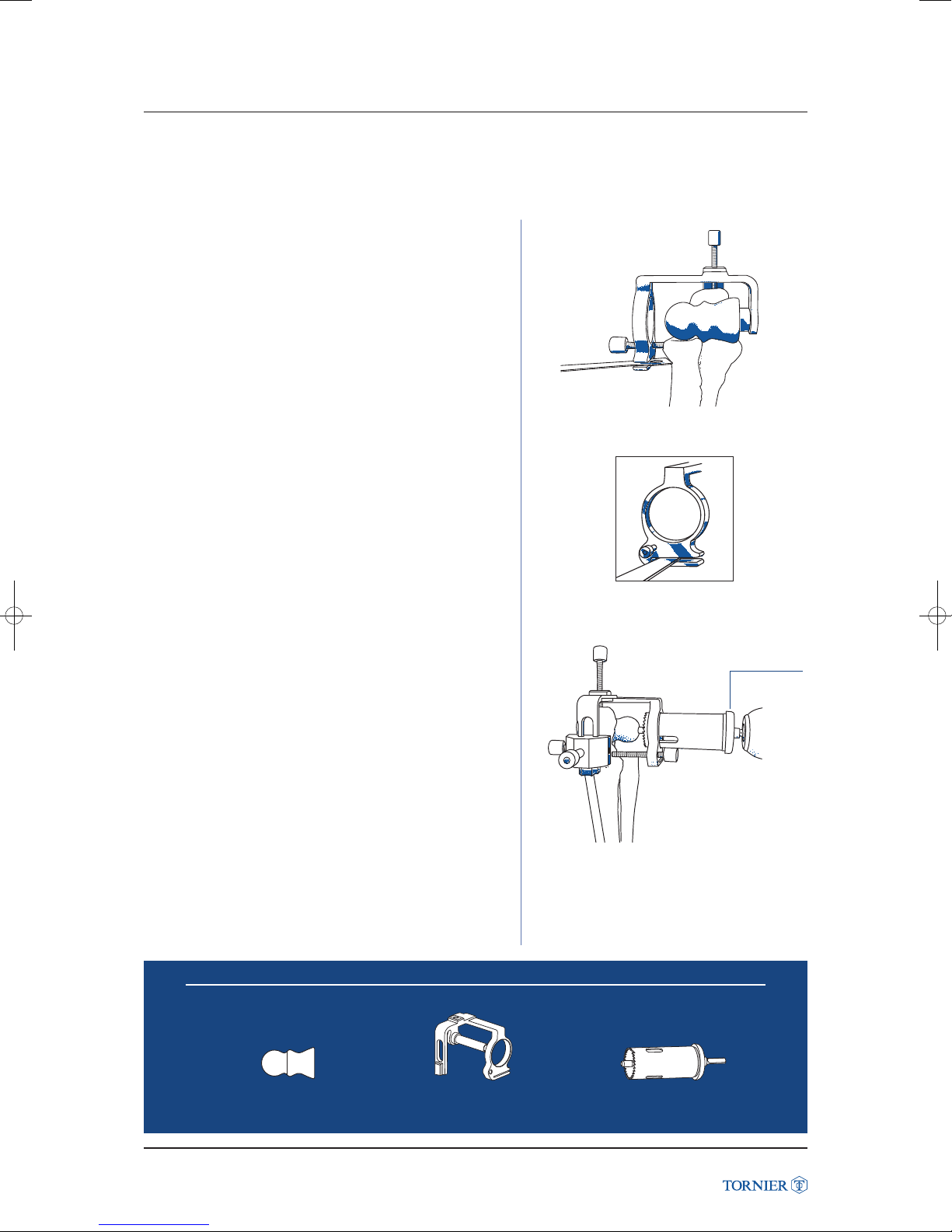
Resect the radial head with an oscillating saw (fig. 41).
From lateral to medial.
(fig. 41)
Latitude Elbow Prosthesis
With the appropriate size bell saw, cut the ulna. The cut is
completed when the collar of the saw sits on the lateral ring
(fig. 42). Ensure the ulnar nerve is protected.
Instruments to use
Note
Slot thickness
is 1.4 mm.
(fig. 42)
Bell saw
collar
Anatomical spool
Latitude Elbow Prosthesis Surgical Technique UCLT101
Ulnar/radial cutting guide
26
Bell saw
Page 27
8. ULNAR PREPARATION (triceps splitting approach)
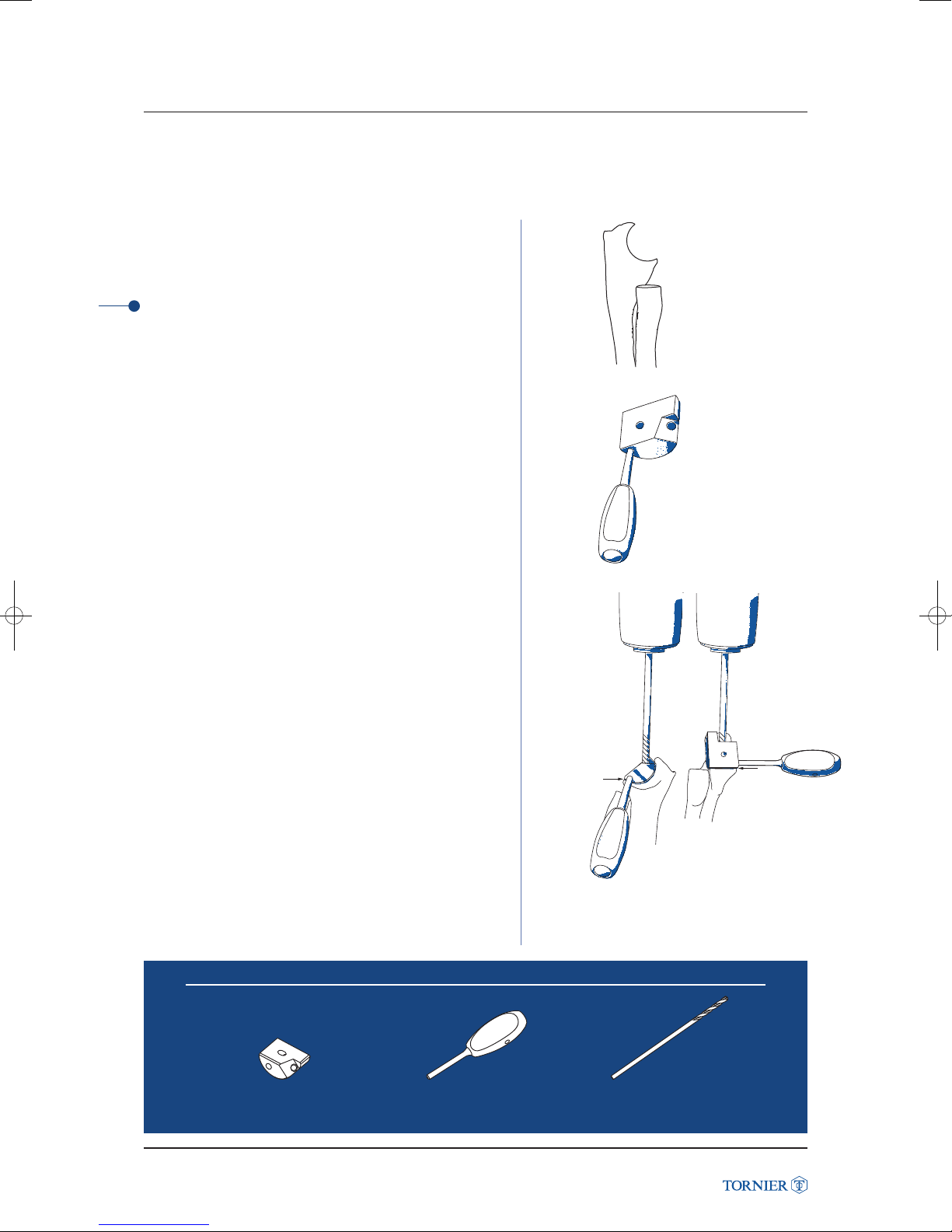
The jig is removed.
Lateral view after all cuts have been completed (fig. 43)
TIP
Irrigate the bell saw continuously while cutting to prevent
overheating.
(fig. 43)
Attach the handle to the appropriate size (S/M/L) and side
(R/L) ulnar diaphysis drill guide (fig. 44a).
(fig. 44a)
Place the drill guide in the sigmoid cut and drill the ulnar
canal with the 4.5 mm drill bit to the depth of the mark
corresponding to the size of the implant (fig. 44b).
The tip of the olecranon can be removed with a rongeur
if necessary.
Note
The position of the guide should be aligned as shown
with reference to the tip of the coranoid and olecranon.
Instruments to use
Latitude Elbow Prosthesis
(fig. 44b)
Ulnar diaphysis axis
drill guide
Latitude Elbow Prosthesis Surgical Technique UCLT101
Ulnar diaphysis axis
drill guide handle
27
Ulnar diaphysis axis drill bit
Page 28
ULNAR PREPARATIO
8. ULNAR PREPARATION (triceps splitting approach)
2 Ulnar canal Broaching
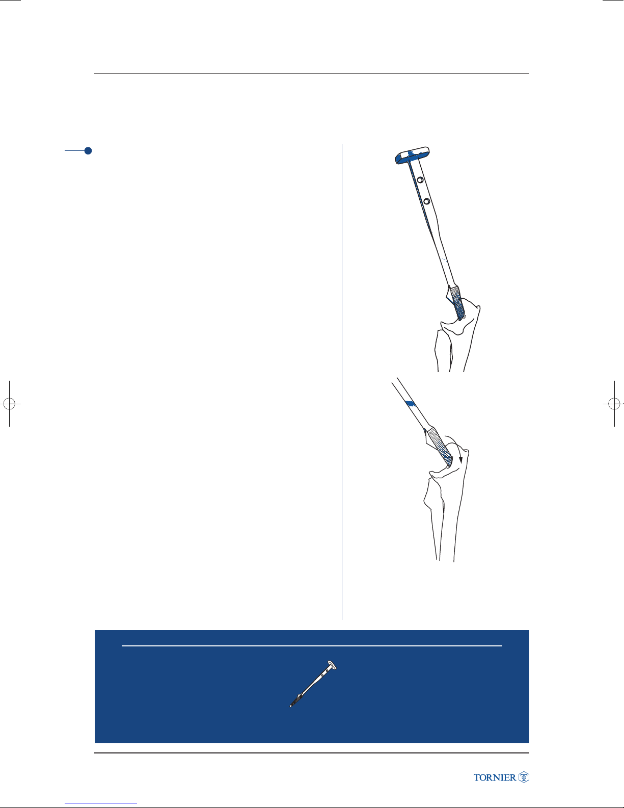
Broach the ulnar diaphysis canal beginning with the starting
broach and broach sequentially to the desired size (fig. 45).
Latitude Elbow Prosthesis
Insert the broach in the ulnar canal respecting the radial
inclination of the shaft. (fig. 46). Use the orientation of the flat
spot on the posterior surface of the ulna to assist in correctly
rotating the ulnar broach.
Instruments to use
(fig. 45)
(fig. 46)
Latitude Elbow Prosthesis Surgical Technique UCLT101
Ulnar broaches
28
Page 29
8. ULNAR PREPARATION (triceps splitting approach)
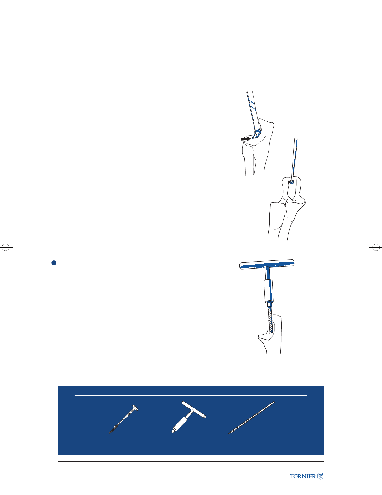
Broach until the apex of the fin is in contact with the bone
(fig. 47a).
Note
Do not broach beyond this point.
Burr slightly the olecranon to facilitate seating of the trial
and implant (fig. 47b).
Should a standard ulnar stem be desired, ream the canal
for the final implant with the ulnar reamer (fig. 47c)
or a flexible boring.
(fig. 47a)
3 Ulnar canal reaming for standard stem
Assemble the reamer to the handle.
Gently ream the canal making sure not to penetrate the lateral
or dorsal cortex (fig. 47c). Flexible reamers (not included),
can be used if preferred.
Instruments to use
(fig. 47b)
Latitude Elbow Prosthesis
(fig. 47c)
Ulnar broaches
Latitude Elbow Prosthesis Surgical Technique UCLT101
Ulnar reamer handle
29
Ulnar reamer
Page 30
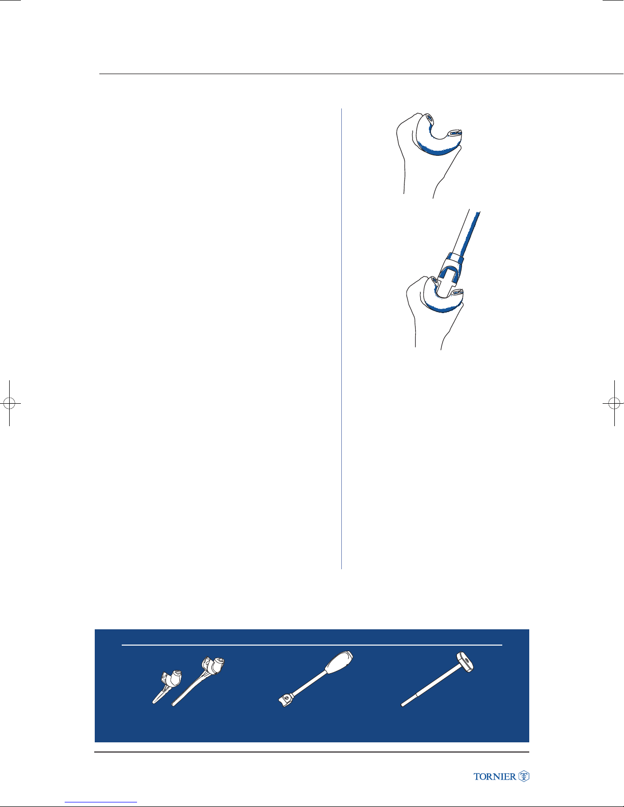
ULNAR TRIAL AND RAD
9. ULNAR TRIAL AND RADIUS PREPARATION
ULNAR TRIAL
Select the appropriate ulnar trial according to side, size
and desired length.
Position the trial stem in the ulnar canal and then seat it flush
with the ulna using the impactor (fig. 48a-b).
(fig. 48a)
(fig. 48b)
Latitude Elbow Prosthesis
Instruments to use
Trial ulnar stems
Latitude Elbow Prosthesis Surgical Technique UCLT101
Impactor
30
Trial radial stem impactor
Page 31
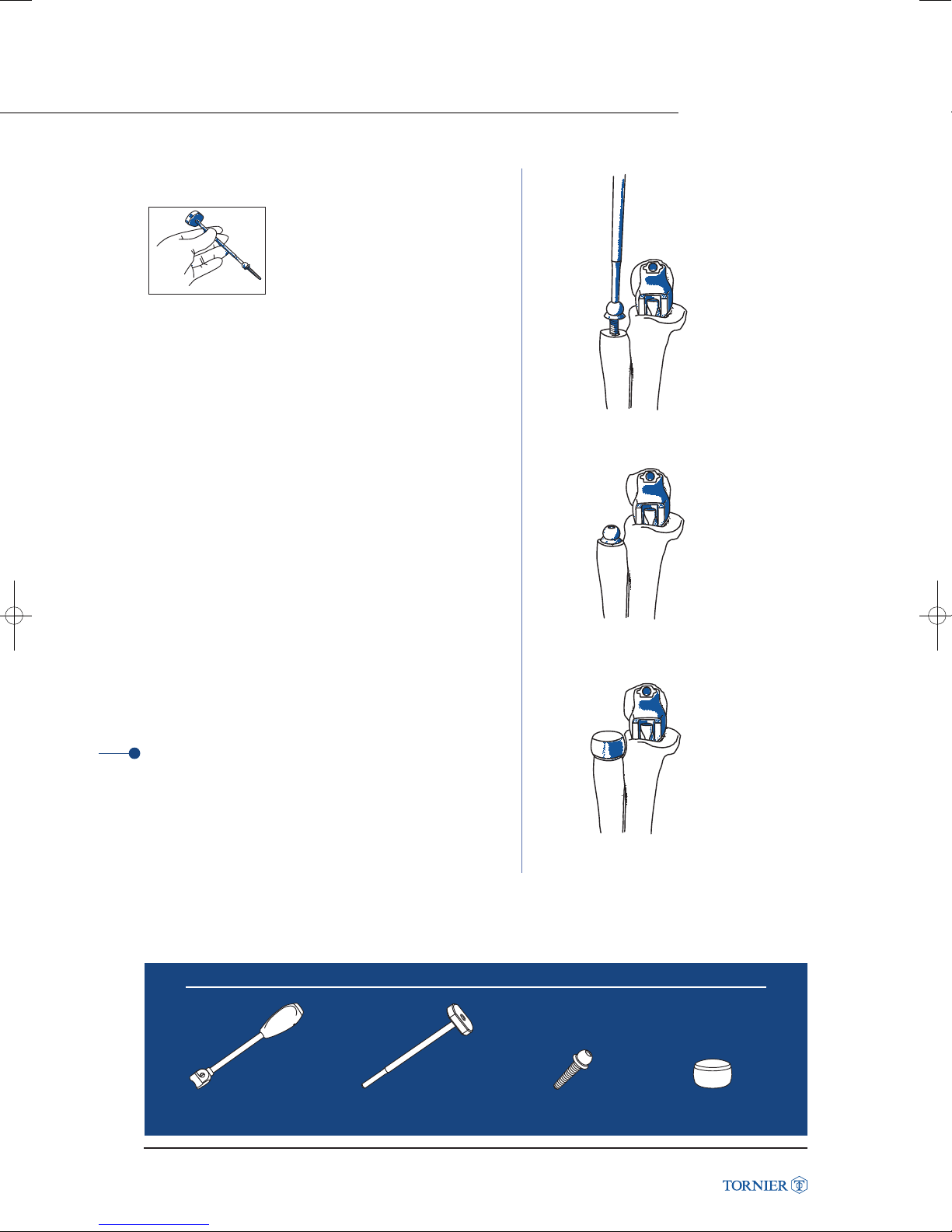
RADIUS PREPARATION AND TRIAL
Screw the trial handle to the radial
broach/trial stem (fig. 49).
(fig. 49)
Starting with the 5 mm radial broach, tap the handle
until the collar of the broach seats on the resected surface.
If a larger stem is desired, broach next with the 6.5 mm
broach (fig. 50).
Upon completion, unscrew the handle leaving the broach
seated in the canal (fig. 51a).
(fig. 50)
Using the same color code, select the appropriate size trial
radial head and place the trial head on the stem (fig. 51b).
TIP
The radial head trial seats freely on the stem
and is not a snap fit.
Instruments to use
(fig. 51a)
(fig. 51b)
Latitude Elbow Prosthesis
Impactor
Latitude Elbow Prosthesis Surgical Technique UCLT101
Trial radial stem impactor
31
Trial radial stem
Trial radial head
Page 32
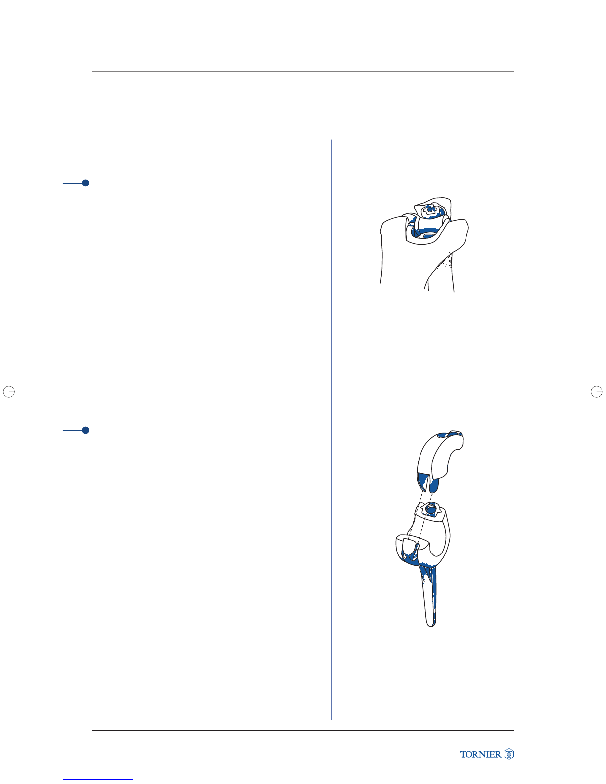
TRIAL AND REDUCTIO
10. TRIAL AND REDUCTION
The trial components can be placed unlinked or linked.
1 Unlinked
Reduce the humeral and ulnar components (fig. 52).
Perform the initial trial reduction by placing the triceps in its
anatomic position. The elbow should articulate through a full
ROM, testing for stability, articular tracking, axis of rotation
and range of motion.
If the trial reduction is satisfactory, remove the trial
components and prepare the elbow for the final implants.
If the trial reduction is not satisfactory, check that the trial
implants are correctly positioned and that no soft tissue
impingement has occurred.
In case of an unstable elbow, use the trial cap to link
the implant.
Latitude Elbow Prosthesis
2 Linked
Assemble the trial ulnar cap as shown (fig. 53a-d) to the ulnar
stem and tighten the trial locking screw. Confirm appropriate
component placement and perform another trial reduction.
Perform the initial trial reduction by placing the triceps in its
anatomic position. The elbow should articulate through a full
ROM, testing for stability, axis of rotation and range of
motion.
(fig. 52)
If the trial reduction is satisfactory, remove the trial
components and prepare the elbow for the final implants.
If the trial reduction is not satisfactory,
check that the trial stems sit properly on the bone
and that no soft tissue impingement has occurred.
Latitude Elbow Prosthesis Surgical Technique UCLT101
(fig. 53a)
32
Page 33
If the radial head articulates congruently with the capitellum,
a radial head component should be employed.
If maltracking of the radial head is evident, component
positioning should be adjusted. If maltracking persists,
a radial head replacement should not be performed.
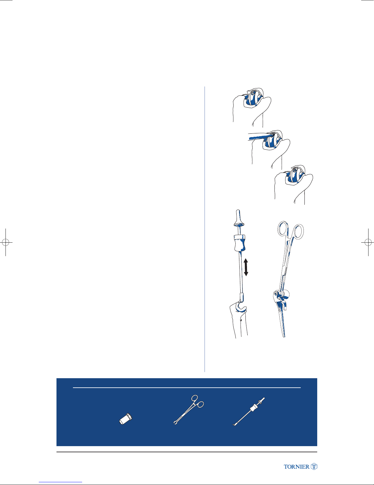
After the trial reduction is complete, remove the trial stems.
To remove the trial radial stem, screw the radial trial handle
into the screw hole of the radial trial stem.
Gently tap with a mallet to extract the stem. Remove the ulnar
trial stem using the ulnar stem extractor tool (fig. 54).
To remove the humeral component, grasp the humeral trial
spool with the humeral extractor clamp (fig. 55).
Then gently tap retrograde and remove the component.
(fig. 53b)
(fig. 53c)
(fig. 53d)
Latitude Elbow Prosthesis
Optional trial
ulnar screw
Latitude Elbow Prosthesis Surgical Technique UCLT101
Instruments to use
Humeral component
extractor
33
(fig. 54)
(fig. 55)
Ulnar stem extractor
Page 34
CEMENT TECHNIQUE A
11. FINAL IMPLANT ASSEMBLY
After all trial components have been removed, lavage and dry all medullary canals.
Cement restrictors should be considered.
ASSEMBLY OF FINAL COMPONENTS
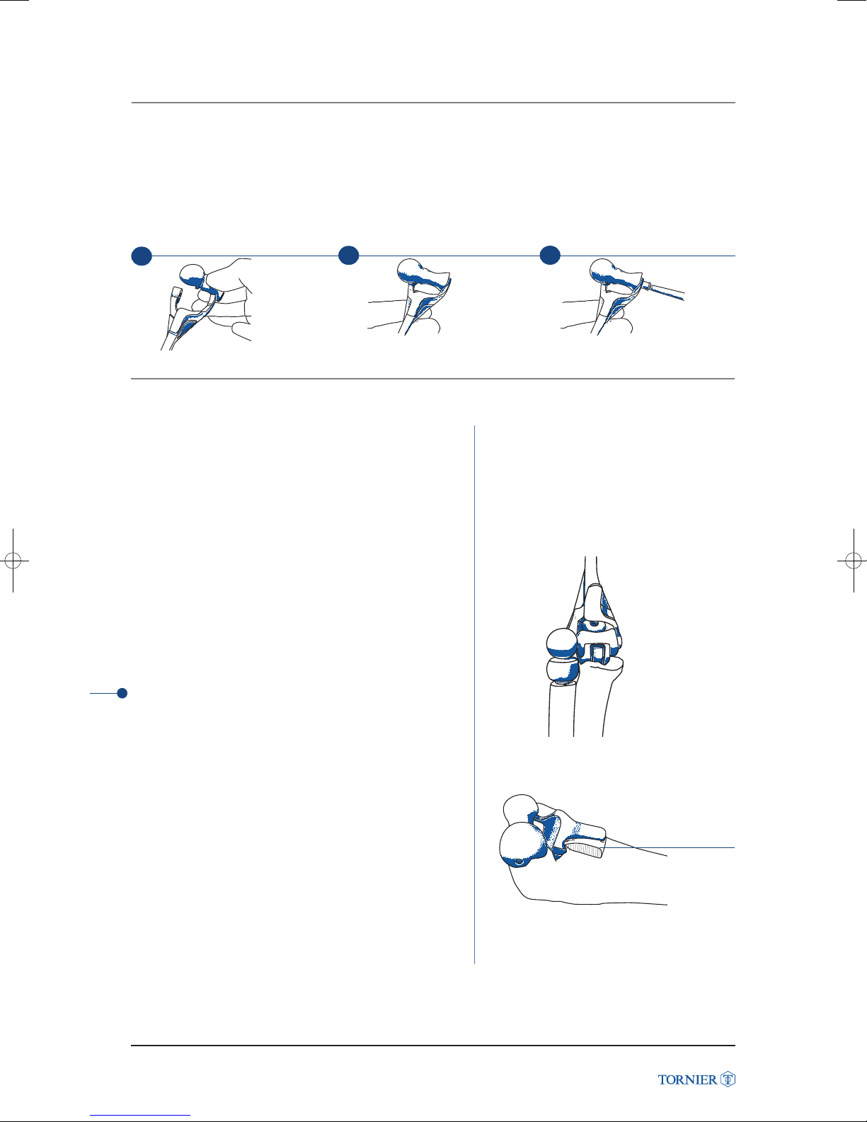
The humeral stem (side and size) is assembled to the appropriate spool (side, size and offset).
The implant humeral screw (cannulated) is firmly tightened with the 4.5 mm hex screwdriver (fig. 56a-c).
1
(fig. 56a)
2
12. CEMENT TECHNIQUE AND BONE GRAFT
CEMENT TECHNIQUE
Insert a cement restrictor in each canal thanks to cement
restrictor inserter.
Using a cement gun, antibiotic laden bone cement is injected
retrograde into the humeral canal, and antegrade into
the ulnar and radial canals. The stems of the ulnar and radial
Latitude Elbow Prosthesis
components are precoated with cement to improve
the implant cement bond. The components are placed into
position, removing all excess cement, particularly around
the bipolar radial head component. Depending on preference,
the radial and ulnar components can be cemented first
and then the humerus or all three can be cemented
simultaneously.
Check that the spool sits properly on the humeral component.
3
(fig. 56b)
(fig. 56c)
TIP
When using the radial head component, cement both radial
head and ulnar stem at the same time. To ensure that both
components are seated at the same level, use the trial
humeral stem and spool as a visual guide to correct insertion
(fig. 57).
Anterior Flange Bone Graft
A cancellous bone fragment from the resected bone of the
distal humerus is fashioned to fit between the humeral shaft
and the anterior flange of the humeral component.
The bone graft is wedged firmly in place (fig. 58).
Unlinked
• The supplied ulnar screw is left in the ulnar component.
• Proceed with ligament repair and closure.
34
Latitude Elbow Prosthesis Surgical Technique UCLT101
(fig. 57)
Bone graft
(fig. 58)
Page 35
12. CEMENT TECHNIQUE AND BONE GRAFT
Linked
• Cement each component according to the technique
described. Wait until cement has set. Leave protecting ulnar
screw in its component to prevent cement from coming
in contact with the threads. Avoid any movement of the
elbow while the cement is setting as movement decreases
the bond of cement to the components.
• Assemble the 2.5 mm screwdriver with the torque handle.
• When cement has completely set, remove the protecting
ulnar screw with the 2.5 mm hex screw driver and discard.
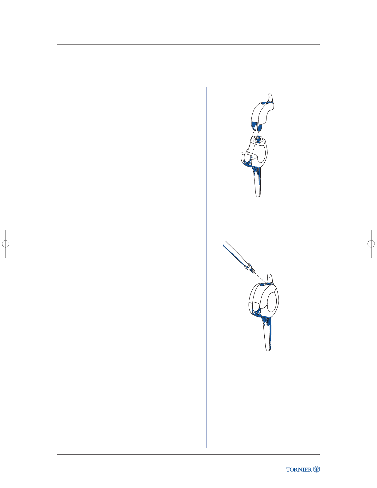
• Reduce humeral and ulnar components to approximately
140° of flexion, insert ulnar cap into the ulnar stem (fig. 59).
(fig. 59)
• Tighten the screw until the torque release is reached
(fig. 60).
Latitude Elbow Prosthesis
(fig. 60)
Latitude Elbow Prosthesis Surgical Technique UCLT101
35
Page 36
CEMENT TECHNIQUE
AND BONE GRAFT
12. CEMENT TECHNIQUE AND BONE GRAFT
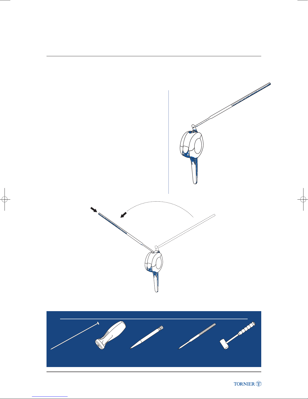
• Using the tab bending tool and a mallet (fig. 61a),
bend the cap tab over the screw (fig. 61b).
Latitude Elbow Prosthesis
Instruments to use
(fig. 61a)
(fig. 61b)
Torque handleCement restrictor inserter
Latitude Elbow Prosthesis Surgical Technique UCLT101
Torgue screwdriver adaptator
36
Ulnar cap lug bending tool
Mallet
Page 37
SUTURE TECHNIQUE
AND CLOSURE
13. SUTURE TECHNIQUE AND CLOSURE
1 Suture technique
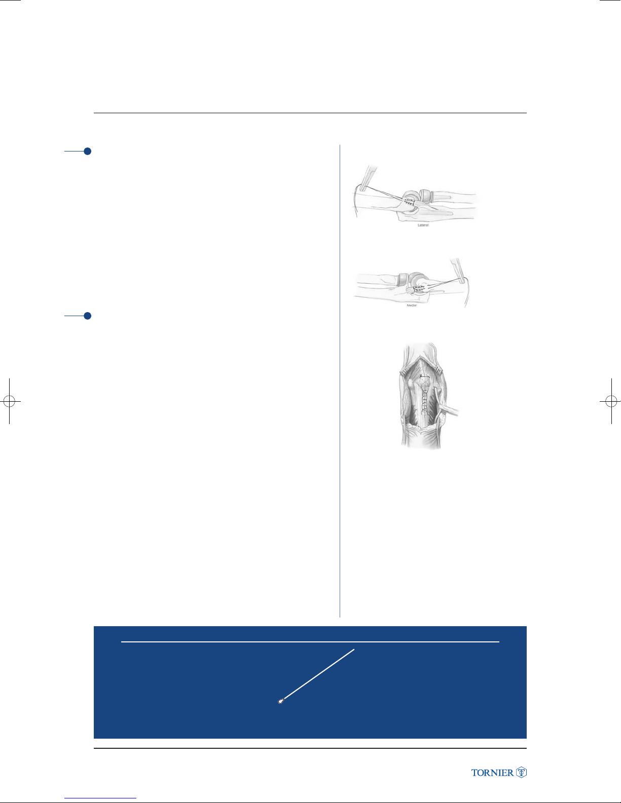
Using #1 FiberwireTM, Krackow sutures are placed in the
medial and lateral collateral ligaments and common flexor
and extensor origins respectively. Utilizing suture passer,
the sutures are drawn through the cannulated humeral screw
in the implant and tied. The suture ends are passed around
the ulna and tied to prevent elbow subluxation in the
postoperative period.
The triceps is repaired to the olecranon using #5 Ethibond
suture with locking Krackow technique. Drill holes are placed
in the ulna to ensure a strong postoperative repair.
(fig. 62a)
TM
2 Postoperative recommendations
• Unlinked TEA
The elbow is splinted at 60° in a well padded splint for 24-48
hours depending on skin quality. Active flexion and gravity
assisted extension is performed with forearm in neutral
rotation. Active extension is avoided for 6 weeks to protect
the triceps repair. Prosupination is performed with the elbow
in flexion.
A collar and cuff or sling is used between exercises for
the first 6 weeks. Extension splinting at night may be used
to assist in regaining elbow extension after four weeks.
Light strengthening is initiated 10 weeks postoperatively.
• Linked TEA
The elbow is splinted in full extension with a well padded
splint for 24-48 hours. Active flexion and prosupination
is performed without restriction. Gravity assisted extension
is used to protect the triceps repair for 6 weeks. If a triceps
sparing approach was used, active extension is permitted
immediately postoperatively. Light strengthening is initiated
10 weeks postoperatively.
Night extension splinting is initiated immediately
postoperatively to maximize elbow extension.
(fig. 62b)
Latitude Elbow Prosthesis
(fig. 63)
FiberwireTMis a trademark from Arthrex, FL.
EthibondTMis a trademark from Johnson & Johnson, NJ.
Latitude Elbow Prosthesis Surgical Technique UCLT101
Instruments to use
Suture passer
37
Page 38
ASSEMBLY
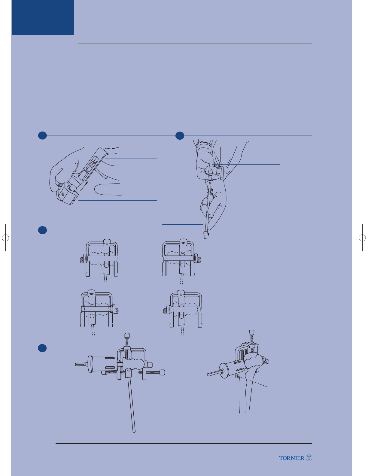
• Components required to assemble the triceps on ulnar cutting guide:
- Triceps on cutting guide.
- Sliding screw support.
- Forearm axis guide.
- 4 locking screws: flat/trochar/cannulated (Ø 2 mm).
• Choose the appropriate side cutting guide, one size fits all.
• Assemble the cutting guide as shown (see assembled cutting guide fig. (64a-d).
ASSEMBLY
14. RADIO-ULNAR TRICEPS ON CUTTING GUIDE
1
Cutting guide
(fig. 64a)
Sliding screen
support
Slide the screw support
onto the cutting guide.
3
Latitude Elbow Prosthesis
Right
Left
Medial Lateral
(fig. 64c)
(fig. 64d)
Forearm axis guide
2
Triceps on
(fig. 64b)
Screw the forearm axis
guide into the cutting
guide.
Assemble the spool
support to the jig on
either side depending
on whether the ulnar
cut is to be made from
lateral or medial.
Medial
4
Screw the 4 desired type screws
(cannulated, trochar or flat) into the
cutting guide. Insert the selected
spool on the cutting axis.
Latitude Elbow Prosthesis Surgical Technique UCLT101
The radial head cut is
performed at the level
of the notch on the side
of the triceps on guide.
38
Page 39
REVISION
15. REVISION
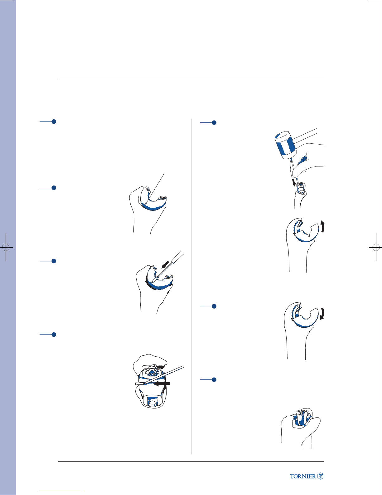
Step 1
Remove the mantle of cement surrounding the ulnar
plastic component using a burr, an osteotome or any
other device.
Assembly pin
Step 2
Locate the position
of the assembly pin
from the medial side
(picture 1).
(picture 1)
Step 3
Using a burr, an osteome
or any other device remove
the plastic to get full access
to the pin (picture 2).
(picture 2)
Step 4
From the lateral side, using
a tapered device, such as
the tab bending tool,
and a hammer, gently
remove the pin from
the plastic/metal interface
(picture 3).
(picture 3)
Step 5
Once the pin has been
removed, the ulnar plastic
bushing can be slide off
the ulnar stem.
It can be helpful to use a
tapered tool and a hammer
to remove the plastic part as
shown on pictures 4 and 5.
(picture 4)
Latitude Elbow Prosthesis
(picture 5)
Step 6
Position the new plastic bushing
on the ulnar stem and rotate it on
the slide channel until it is flush,
fully engaged (picture 6).
(picture 6)
Step 7
The ulnar cap must be assembled to the ulnar
stem after revision of the plastic bushing.
Indeed, the ulnar cap is the only
way to secure the plastic
bushing on the ulnar stem
(picture 7).
Latitude Elbow Prosthesis Surgical Technique UCLT101
(picture 7)
39
Page 40
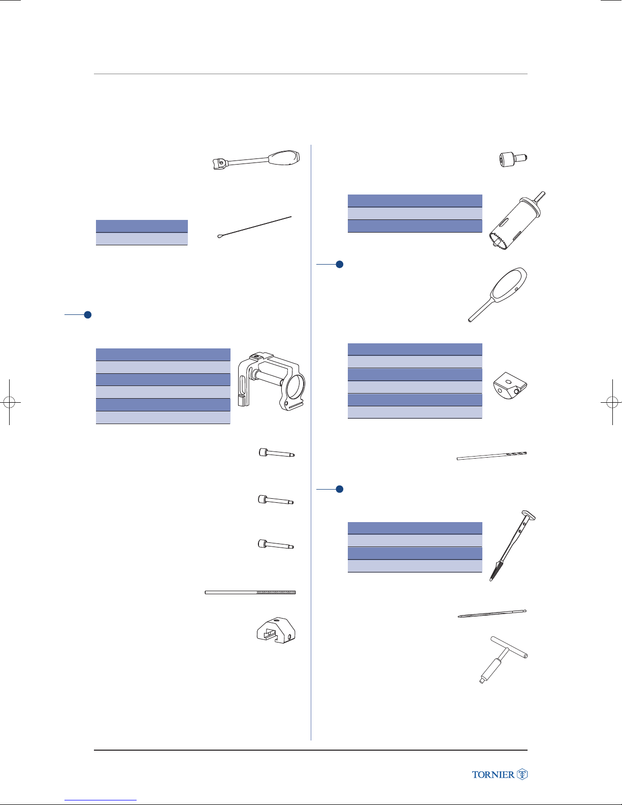
INSTRUMENTATION
INSTRUMENTATION
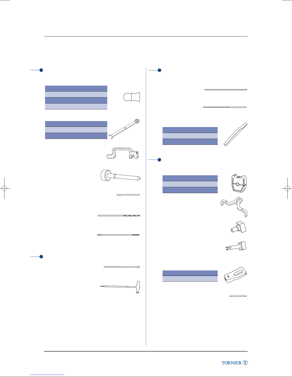
Drilling of flexion / extension axis
Anatomical spool
Small size Ref. MKY032
Medium size Ref. MKY034
Large size Ref. MKY036
Large + Ref. MKY138
Capitellum radii gauge
Small size Ref. MKY002
Medium size Ref. MKY004
Large size Ref. MKY006
Guide
of flexion/extension axis
Ref. MKY001
Drill of flexion/extension
axis
Ref. MKY119
Latitude Elbow Prosthesis
Stabilization pin
length 110 mm - Ø 3
Ref. MJU051
Drill bit for flexion/
extension axis - Ø 3
Ref. MKY061
Reamer - Ø 3
Ref. MDS460
Humeral diaphysis drilling
Burr - Ø 6
Ref. MKY058
Humeral diaphysis
reamer - Ø 6
Ref. MKY007
Offset determination
Axis - Ø 2,8 L180 flexion/extension
Ref. MKY018
Humeral diaphysis axis
Ref. MKY019
Offset determining gauge
Small size Ref. MKY008
Medium size Ref. MKY009
Large size Ref. MKY010
Humeral trochlea cut
Humeral trochlea cutting block
Small size Ref. MKY012
Medium size Ref. MKY013
Large size Ref. MKY014
Humeral trochlea
cutting guide support
Ref. MKY015
Assembly screw for
humeral trochlea cut
Ref. MKY016
Diaphysis aiming guide
Ref. MKY017
“No trochlea” humeral
cutting guide support
Right side Ref. MKY059
Left side Ref. MKY060
Stabilization pin
Ø 3 - Length 55 mm
Ref. MKY062
Latitude Elbow Prosthesis Surgical Technique UCLT101
40
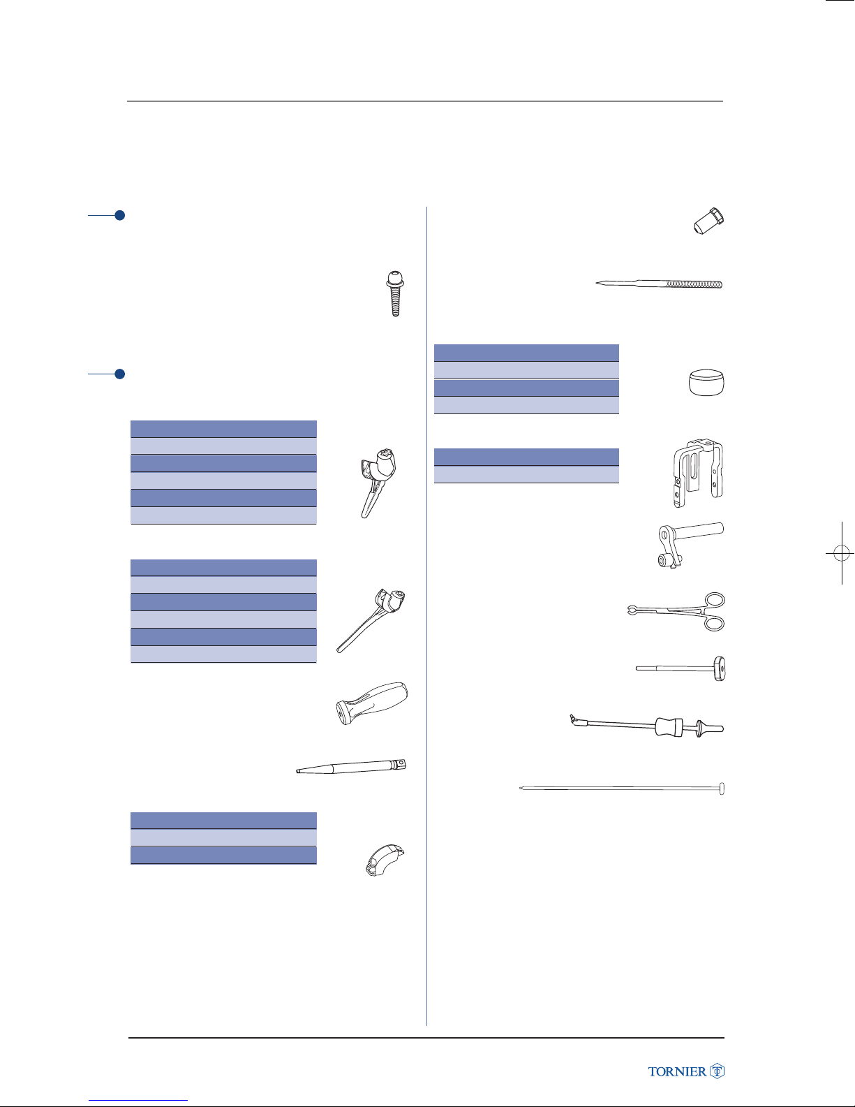
Page 41
INSTRUMENTATION
INSTRUMENTATION
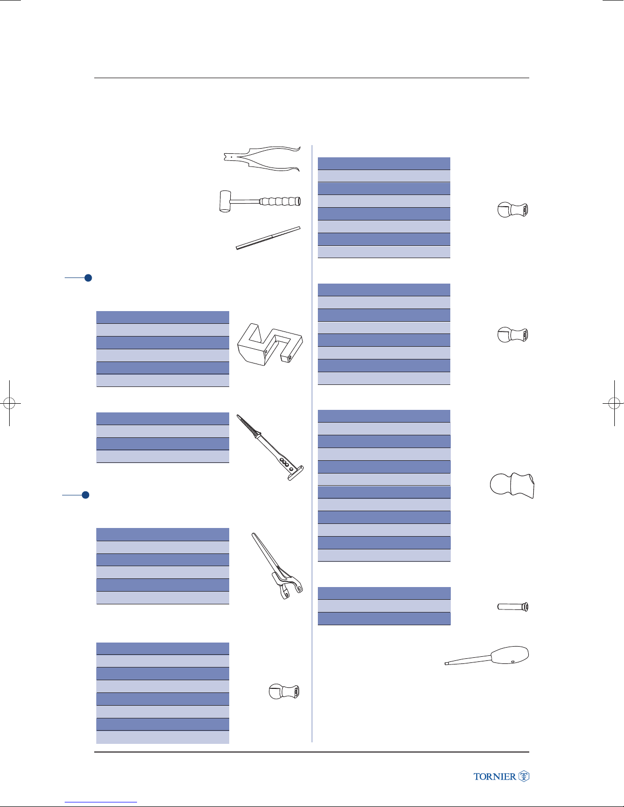
Pin puller
Ref. MCI511
Mallet
Ref. MWA122
Osteotome
Ref. MDU500
Humeral capitellum cut
Capitellum cutting guide
Small, right Ref. MKY020
Small, left Ref. MKY021
Medium, right Ref. MKY022
Medium, left Ref. MKY023
Large, right Ref. MKY024
Large, left Ref. MKY025
Humeral diaphysis canal broach
Starting size Ref. MKY063
Small Ref. MKY026
Medium Ref. MKY028
Large Ref. MKY030
Humeral trial parts
Trial humeral stem
Small, right Ref. MKY080
Small, left Ref. MKY081
Medium, right Ref. MKY082
Medium, left Ref. MKY083
Large, right Ref. MKY084
Large, left Ref. MKY085
Trial spool anterior offset
Small size, right Ref. MKY086
Small size, left Ref. MKY089
Medium size, right Ref. MKY087
Medium size, left Ref. MKY090
Large size, right Ref. MKY088
Large size, left Ref. MKY091
Large + size, right Ref. MKY139
Large + size, left Ref. MKY140
Trial spool centered offset
Small, right Ref. MKY098
Small, left Ref. MKY101
Medium, right Ref. MKY099
Medium, left Ref. MKY102
Large, right Ref. MKY100
Large, left Ref. MKY103
Large +, right Ref. MKY141
Large +, left Ref. MKY142
Trial spool posterior offset
Small, right Ref. MKY092
Small, left Ref. MKY095
Medium, right Ref. MKY093
Medium, left Ref. MKY096
Large, right Ref. MKY094
Large, left Ref. MKY097
Large +, right Ref. MKY143
Large +, left Ref. MKY144
Anatomic Spool
Small, right Ref. MKY151
Small +, right Ref. MKY152
Medium, right Ref. MKY153
Medium +, right Ref. MKY154
Large, right Ref. MKY155
Large +, right Ref. MKY156
Small, left Ref. MKY161
Small +, left Ref. MKY162
Medium, left Ref. MKY163
Medium +, left Ref. MKY164
Large, left Ref. MKY165
Large +, left Ref. MKY166
Trial humeral screw
Small size Ref. MKY104
Medium size Ref. MKY105
Large size Ref. MKY106
Hexagonal screwdriver
Ø 4,5 mm
Ref. MHG001
Latitude Elbow Prosthesis
Latitude Elbow Prosthesis Surgical Technique UCLT101
41
Page 42
INSTRUMENTATION
INSTRUMENTATION
Impactor
Ref. MKY064
Suture passer
Ref. MKY079
Base Ref. YRAD321
Insert Ref. YRAD322
Box lid
Ref. NCR001
Ulnar/radial cut
Ulnar/radial cutting guide
Small size, right Ref. MKY040
Small size, left Ref. MKY041
Medium size, right Ref. MKY042
Latitude Elbow Prosthesis
Medium size, left Ref. MKY043
Large size, right Ref. MKY044
Large size, left Ref. MKY045
Tightening screw
Ø M5 - triangular tip
Ref. MKY071
Locking screw
Ref. MKY054
Bell saw
Small size Ref. MKY037
Medium size Ref. MKY038
Large size Ref. MKY039
Ulnar diaphysis drilling
Ulnar diaphysis drill
guide handle
Ref. MKY048
Ulnar diaphysis drill guide
Small size, right Ref. MKY051
Small size, left Ref. MKY069
Medium size, right Ref. MKY050
Medium size, left Ref. MKY067
Large size, right Ref. MKY049
Large size, left Ref. MKY065
Ulnar diaphysis axis drill bit
Ref. MKY070
Tightening screw
Ø M5 - flat tip
Ref. MKY072
Cannulated tightening screw
Ø M5
Ref. MKY052
Forearm positioning guide
Ref. MKY046
Ulnar/radial cutting guide
sliding block
Ref. MKY047
Latitude Elbow Prosthesis Surgical Technique UCLT101
Ulnar broaches
Ulnar broach
Starting size, Ref. MKY074
Small size Ref. MKY075
Medium size Ref. MKY076
Large size Ref. MKY077
Ulnar reamer - standard stems
Ref. MKY132
Ulnar reamer handle
Ref. MKY131
42
Page 43
INSTRUMENTATION
INSTRUMENTATION
Radial broaches
Trial radial stem - Ø 5 mm
Ref. MKY116
Trial radial stem - Ø 6,5 mm
Ref. MKY117
Ulnar/radial trial parts
Trial ulnar short stem
Small size, right Ref. MKY107
Small size, left Ref. MKY108
Medium size, right Ref. MKY109
Medium size, left Ref. MKY110
Large size, right Ref. MKY111
Large size, left Ref. MKY112
Trial ulnar standard stem
Small size, right Ref. MKY125
Small size, left Ref. MKY126
Medium size, right Ref. MKY127
Medium size, left Ref. MKY128
Large size, right Ref. MKY129
Large size, left Ref. MKY130
Torque handle
Ref. MKY121
Torque screwdriver adaptor
(hexagon 2,5 mm)
Ref. MKY122
Trial ulnar cap
Small size Ref. MKY113
Medium size Ref. MKY114
Large size Ref. MKY115
Spare M5 ulnar screw implant
Ref. DKY066
Ulnar cup lug bending tool
Ref. MKY124
Trial radial head
Small size Ref. MKY055
Medium size Ref. MKY056
Large size Ref. MKY057
Large + size Ref. MKY134
Triceps on jig
Right size Ref. MKY135
Left size Ref. MKY136
Triceps on bell saw jig
Ref. MKY137
Humeral component extractor
Ref. MKY147
Trial radial head impactor
Ref. MKY118
Ulnar stem extractor
Ref. MWA118
Cement insert restrictor
Ref. MKY149
Latitude Elbow Prosthesis
Latitude Elbow Prosthesis Surgical Technique UCLT101
43
Page 44
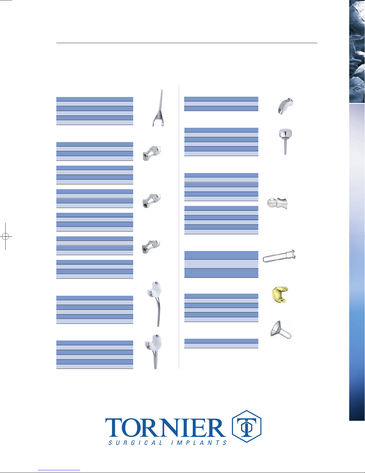
ELBOW PROSTHESIS
ELBOW PROSTHESIS
Humeral Implant
Ref. Component information
DKY181 Humeral implant small right
DKY183 Humeral implant medium right
DKY185 Humeral implant large right
DKY182 Humeral implant small left
DKY184 Humeral implant medium left
DKY186 Humeral implant large left
Spool
Ref. Component information
DKY201 Spool small anterior offset right
DKY203 Spool medium anterior offset right
DKY205 Spool large anterior offset right
DKY2 07 Spool large + anterior offset right
DKY202 Spool small anterior offset left
DKY204 Spool medium anterior offset left
DKY206 Spool large anterior offset left
DKY2 08 Spool large + anterior offset left
DKY221 Spool small posterior offset right
DKY223 Spool medium posterior offset right
DKY225 Spool large posterior offset right
DKY2 27 Spool large + posterior offset right
DKY222 Spool small posterior offset left
DKY224 Spool medium posterior offset left
DKY226 Spool large posterior offset left
Latitude Elbow Prosthesis
DKY2 28 Spool large + posterior offset left
DKY211 Spool small centered offset right
DKY213 Spool medium centered offset right
DKY215 Spool large centered offset right
DKY2 17 Spool large + centered offset right
DKY212 Spool small centered offset left
DKY214 Spool medium centered offset left
DKY216 Spool large centered offset left
DKY2 18 Spool large + centered offset left
Anterior
Posterior
Centered
Standard Ulnar Stem
Ref. Component information
DKY071 Standard ulnar stem small right
DKY072 Standard ulnar stem medium right
DKY073 Standard ulnar stem large right
DKY075 Standard ulnar stem small left
DKY076 Standard ulnar stem medium left
DKY077 Standard ulnar stem large left
Short Ulnar Stem
Ref. Component information
DKY081 Ulnar stem small right
DKY082 Ulnar stem medium right
DKY083 Ulnar stem large right
DKY085 Ulnar stem small left
DKY086 Ulnar stem medium left
DKY087 Ulnar stem large left
Ulnar Cap
Ref. Component information
DKY067 Ulnar cap small
DKY068 Ulnar cap medium
DKY069 Ulnar cap large
Radial Components
Ref. Component information
DKY056 Radial head small
DKY057 Radial head medium
DKY058 Radial head large
DKY059 Radial head large +
DKY061 Radial stem diam. 6.5 mm
DKY062 Radial stem diam. 5 mm
Anatomic Spool
Ref. Component information
DKY161 Anatomic spool small, right
DKY162 Anatomic spool small +, right
DKY163 Anatomic spool medium, right
DKY 164 Anatomic spool medium +, right
DKY165 Anatomic spool large, right
DKY166 Anatomic spool large +, right
DKY171 Anatomic spool small, left
DKY172 Anatomic spool small +, left
DKY173 Anatomic spool medium, left
DKY 174 Anatomic spool medium +, left
DKY175 Anatomic spool large, left
DKY176 Anatomic spool large +, left
Humeral Screw
Ref. Component information
DKY191 Humeral screw small,
DKY192 Humeral screw medium,
DKY193 Humeral screw large,
small +
medium +
large +
Ulnar Bushing
Ref. Component information
DKY120 Ulnar bushing small, right
DKY121 Ulnar bushing medium, right
DKY122 Ulnar bushing large, right
DKY123 Ulnar bushing small, left
DKY124 Ulnar bushing medium, left
DKY125 Ulnar bushing large, left
Ulnar Restrictor
Ref. Component information
EBO101 Ulnar restrictor Ø 24
EBO102 Ulnar restrictor Ø 13
161, rue Lavoisier. Montbonnot. 38334 Saint-Ismier Cedex. France. Tel.: 33 (0)4 76 61 35 00. Fax: 33 (0)4 76 61 35 33. www.tornier.com
www.tornier.com
UCLT101
 Loading...