

Page 1

INSTALLATION AND MAINTENANCE MANUAL FOR
DIESEL ENGINE FIRE PUMP CONTROLLERS
MODEL HFD
1
Page 2
HFD-Manual-EN v1.4.0.0
Table of Contents
1. Introduction
2. Installation
3. Main Features
4. Home
5. Alarms
6. Configuration
7. History
8. Technical Documents
2
Page 3

Table of Contents
Introduction ...................................................................................................................................................................... 5
Types of Diesel Engine Fire Pump Controllers .......................................................................................................... 5
Methods of Starting/Stopping ..................................................................................................................................... 5
Installation ....................................................................................................................................................................... 7
Location ...................................................................................................................................................................... 7
Mounting .................................................................................................................................................................... 7
Storage ....................................................................................................................................................................... 7
Wiring and Connections ............................................................................................................................................. 7
Electrical Connections................................................................................................................................................ 7
Energy Consumption .................................................................................................................................................. 8
Sizing.......................................................................................................................................................................... 8
Incoming Power Connections .................................................................................................................................... 8
Circuit protection ........................................................................................................................................................ 8
Terminal Strip Descriptions ........................................................................................................................................ 9
Quick Start-Up Guide ............................................................................................................................................... 10
Main Features ............................................................................................................................................................... 14
The ViZiTouch .......................................................................................................................................................... 14
Alarm Bell ................................................................................................................................................................. 15
First Setup ................................................................................................................................................................ 15
Home ............................................................................................................................................................................. 16
Home (Membrane button) ........................................................................................................................................ 16
Screen Saver ........................................................................................................................................................... 17
Alarms ........................................................................................................................................................................... 18
Alarms (Membrane button) ...................................................................................................................................... 18
Configuration ................................................................................................................................................................. 21
Config (Membrane button) ....................................................................................................................................... 21
NumPad Page .......................................................................................................................................................... 22
Date and Time Page ................................................................................................................................................ 22
User Login Page / KeyPad Page ............................................................................................................................. 23
Advanced Configuration Page ................................................................................................................................. 24
Details of the Advanced Configuration Page ........................................................................................................... 24
Volt-Current Calibration............................................................................................................................................ 24
Timers Page ............................................................................................................................................................. 26
Inputs/Outputs Configuration ................................................................................................................................... 27
Inputs/Outputs Expansion board 1-2-3-4 ................................................................................................................. 29
Update Program Page ............................................................................................................................................. 30
Factory Settings ....................................................................................................................................................... 30
Reset to Factory Settings Page ............................................................................................................................... 31
The Sensors Pages .................................................................................................................................................. 32
H) Tachometer (Engine Speed Switch) ................................................................................................................... 32
3
Page 4

I) Engine Coolant Temperature ................................................................................................................................ 33
J) Engine Oil Pressure ............................................................................................................................................. 34
K) Fuel Level ............................................................................................................................................................ 35
Details of the Debug Page ....................................................................................................................................... 35
Calibration ................................................................................................................................................................ 35
IO Debug .................................................................................................................................................................. 36
Inputs/Outputs Debug .............................................................................................................................................. 36
Interlock Lockout ...................................................................................................................................................... 36
History ........................................................................................................................................................................... 38
History (Membrane button) ...................................................................................................................................... 38
Details of the History Page ...................................................................................................................................... 39
Events Page ............................................................................................................................................................. 39
Download to USB Device ......................................................................................................................................... 39
The Statistics ............................................................................................................................................................ 41
All Time Statistics ..................................................................................................................................................... 41
Technical Documents .................................................................................................................................................... 42
4
Page 5
Diesel engine fire pump controllers are designed to automatically start a diesel engine driven fire pump upon
detection of an automatic start pressure switch in the fire protection system. A diesel engine fire pump controller
provides automatic & manual starting. An automatic start is controlled by a pressure switch or by remote automatic
devices as deluge valve. The "Operate Manual Start Test Pushbutton" implements a way to simulate the use of the
"Emergency Pushbutton" by being activated after an automatic start followed by a stopping of the Firepump, or
following a "Engine Fail to Start" alarm. A manual start is controlled by an Emergency Start pushbutton, hardwired to
the relay board, that can securely start the engine. The diesel engine fire pump controller includes two battery
chargers to maintain the engine batteries continuously charged.
Types of Diesel Engine Fire Pump Controllers
FIRE PUMP CATALOG NUMBER
MODEL No. EXAMPLE : HFD-12-220
Model Prefix HFD
Battery Voltage 12 : 12V 24 : 24V
Incoming Voltage 220: 208/240V 50/60Hz
Methods of Starting/Stopping
The controllers are available as combination automatic / non-automatic.
METHODS OF STARTING
MANUAL START
The automatic engine cranking sequence can be started by pressing the START push button on the ViZiTouch.
REMOTE MANUAL START
The engine can be started from a remote location by momentarily closing a contact of a manual push button.
OPERATE MANUAL START TEST
The engine can be started by using this pushbutton after a “Fail to Start” alarm or after an automatic start followed by
a stop. This method of starting will activate the last cranking starters that did not attempt to crank, and is in parallel
with the “Emergency Start” button.
EMERGENCY START
The engine can be started from the Emergency Start Push Button located behind the breakable cover.
REMOTE AUTOMATIC START, DELUGE VALVE START
The engine can be started from a remote location by momentarily opening a contact of a pressure switch.
SEQUENTIAL START
In case of a multiple pump application, it may be necessary to delay the starting of each motor when there is a water
pressure drop to prevent simultaneous starting of all motors.
METHODS OF STOPPING
MANUAL STOP
Manual stop is done by pressing the STOP push button. Note that pressing the stop push button will stop the engine
only if all starting causes have disappeared.
Introduction
5
EMERGENCY STOP
The emergency stop is always possible in any running condition and is done by pressing the Stop pushbutton for 8
Page 6

seconds. This will activate the “Auto Mode Bypass”, stopping the engine and preventing the engine from starting
automatically. Use only for maintenance operations..
6
Page 7
The controller is built in accordance with the latest edition of the EN-12845 Standard, and also based on the National
Fire Protection Association standard for the Installation of Centrifugal Fire Pumps, NFPA No.20 (Centrifugal Fire
Pumps 2013 Edition).
This controller is designed to be used with non-approved engine, using the control by analog senders (Magnetic
pickup, oil pressure and engine temperature senders, all shown using on-screen gauges on the ViZiTouch. Find
more information on the senders section of this manual.
Location
The controller shall be located as close as practical to the engine/motor it controls and shall be within sight of the
engine/motor. The controller shall be located or protected such that it will not be damaged by water escaping from
pump or pump connections. Current carrying parts of the controller shall be not less than 12 in. (305 mm) above the
floor level.
The controller is suitable for use in locations subject to a moderate degree of moisture, such as a damp basement.
The pump room ambient temperature shall be between 39°F (4°C) and 104°F (40°C) (If a temperature option is
included, see the rating label for maximum temperature).
The standard controller enclosure is rated IP 55. It is the installer's responsibility to insure that either the standard
enclosure meets the ambient conditions or that an enclosure with an appropriate rating has been provided.
Controllers must be installed inside a building and they are not designed for outside environment. The paint color
may change if the controller is exposed to ultraviolet rays for a long period of time.
Mounting
The fire pump controller shall be mounted in a substantial manner on a single incombustible supporting structure.
Wall mounted controllers shall be attached to the structure or wall using all four (4) mounting ears provided on the
controller with hardware designed to support the weight of the controller at a height not less than 12 in. (305 mm)
above floor level. Floor mounted controllers shall be attached to the floor using all holes provided on the mounting
feet with hardware designed to support the weight of the controller. The mounting feet provide the necessary 12 in.
(305 mm) clearance for current carrying parts.
Storage
If the controller is not installed and energized immediately, Tornatech recommend following the instructions from the
chapter 3 of the NEMA ICS 15 standard.
Wiring and Connections
Electrical Connections
A licensed electrician must supervise the electrical connections. The dimension drawings show the area suitable for
incoming power and motor connections. No other location shall be used. Only watertight hub fittings shall be used
when entering the cabinet to preserve the IP rating of the cabinet. The installer is responsible for adequate protection
of the fire pump controller components against metallic debris or drilling chips. Failure to do so may cause injuries to
personnel, damage the controller and subsequently void warranty.
Installation
7
Page 8
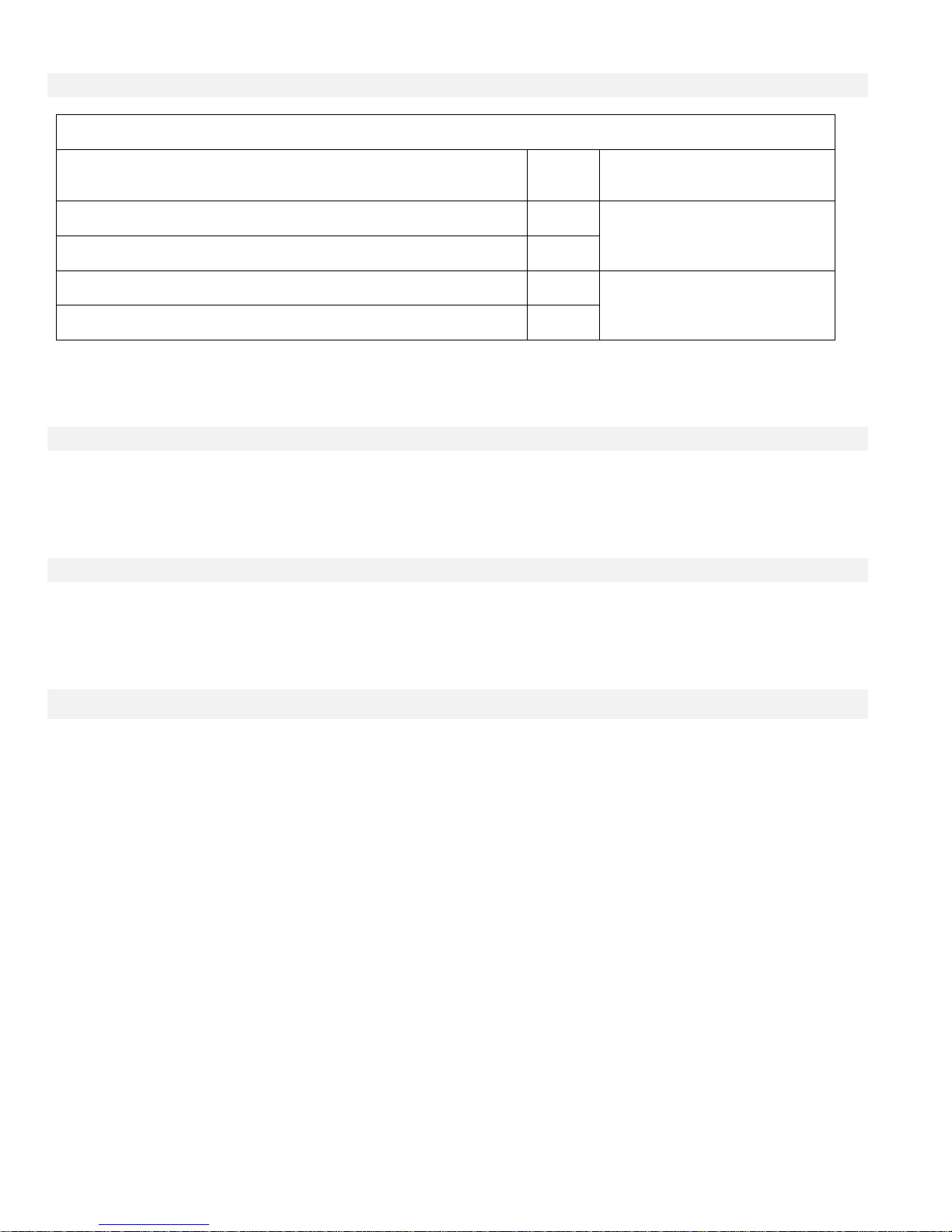
Energy Consumption
Diesel Controller with boost charger
Model / State
220/
240VAC
VDC Output
12VDC / @
No charge
1.0A
13.8V
12VDC / @
Full charge*
4A
24VDC / @
No charge
0.5A
27.6V
24VDC / @
Full charge**
6A
*12 amps through each battery
**10 amps through each battery
Sizing
Wiring between controller and engine (terminals 1,9,10,12) must be stranded #10AWG as minimum.
Wiring between controller and engine (terminals 6,8,11) must be stranded #8AWG as minimum.
Power supply wiring must be stranded #14 AWG as minimum.
Incoming power supply terminals are sized for #16 to #6 AWG wire.
Incoming Power Connections
Diesel engine driven fire pump controllers shall be powered by a dedicated source protected by a fuse or circuit
breaker. Verify the label on the cabinet to select the correct protection. Always follow this procedure when
connecting or disconnecting the controller: Connect both batteries before connecting the AC power. Disconnect the
AC power before disconnecting the batteries. Disconnecting the batteries while the AC is connected may result in
severe damage to the controller electronic boards.
Circuit protection
CB1 protects battery charger 1 and CB2 protects battery charger 2. CB3 protects the control circuit from battery 1
and CB4 protects the control circuit from battery 2.
Always follow this procedure when connecting or disconnecting the controller: Connect both batteries before
connecting the AC power. Disconnect the AC power before disconnecting the batteries.
8
Page 9
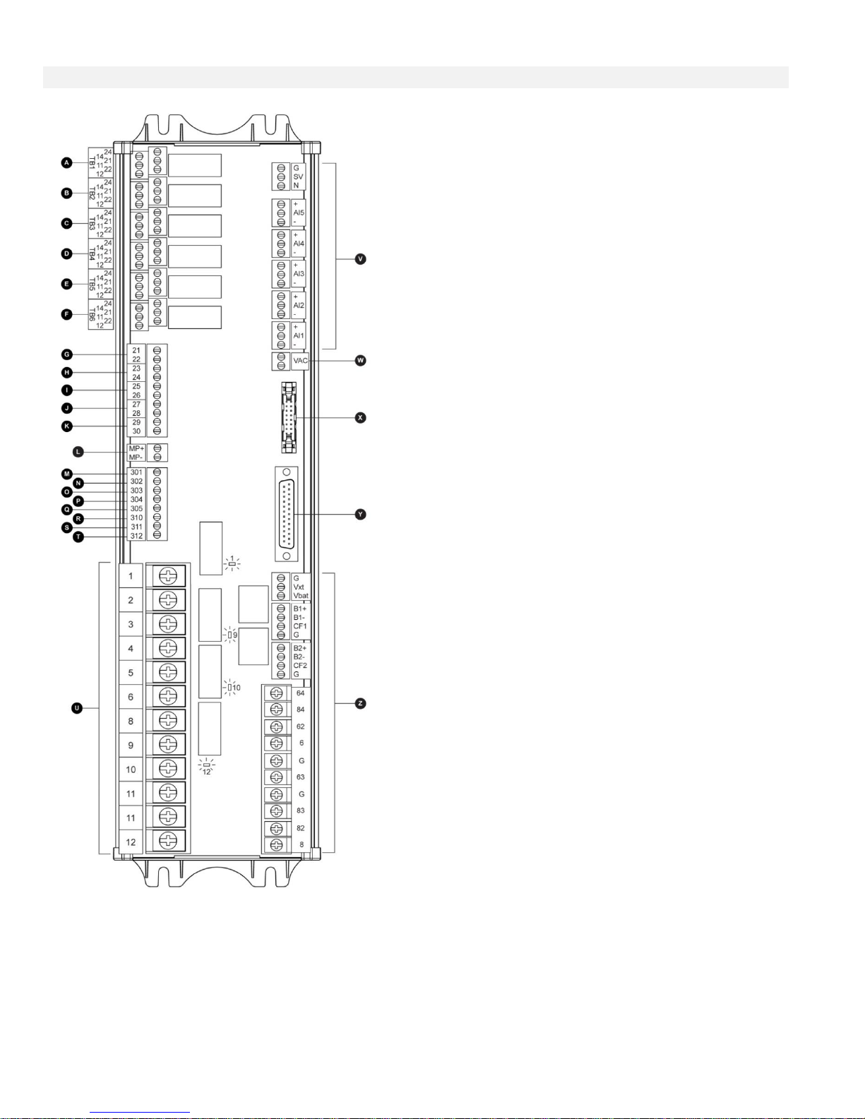
Terminal Strip Descriptions
A-F : Alarm Output Terminals
(DPDT Relay, 11/21:Common, 12/22:Normally Closed,
14/24:Normally Open):
A: Controller Trouble (Fail safe)
B: Engine Run
C: Automatic Mode Bypass (Fail safe)
D: Fail to Start
E: Engine Trouble
F: Pump Room Alarm
G-T : Field Input Terminal
(Dry Contact Only: Voltage Free):
G: Emergency Button
H: Remote Automatic Start (NC)
I: Deluge Valve (NC)
J: Fuel Tank Leak (NO)
K: Low Fuel Level (NO)
L: Engine RPM Magnetic Pickup
M: Not Used
N: Not Used
O: Not Used
P: Not Used
Q: Not Used
R: Not Used
S: Not Used
T: Not Used
U : Engine Terminals :
The terminals are numbered according to the standard:
1 - FS : fuel solenoid valve (energized to start)
2 - Not used
3 - Not used
4 - Not used
5 - Not used
6 - B1 : battery #1 positive
8 - B2 : battery #2 positive
9 - C1 : start contactor #1
10 - C2 : start contactor #2
11 - GND : Ground
12 - ST : stop fuel solenoid valve
(ETS - energized to stop)
V: Analog inputs
SOL V: Not Used
AI1: Not Used
AI2: Not Used
AI3: Oil Pressure transducer
AI4: Fuel Level analog input
AI5: Engine Temperature transducer
W: AC Voltage reading
X: CANBUS to IO cards
Y: CANBUS to ViZiTouch
Z: Factory reserved power connections
9
Page 10
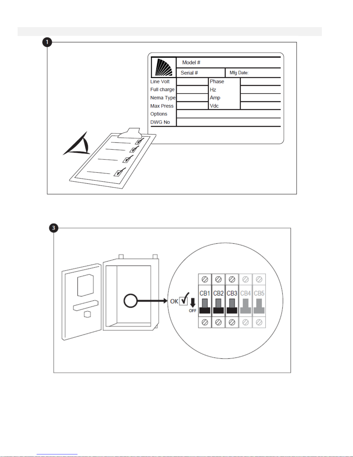
Quick Start-Up Guide
The rating label is the most important label. It must be read carefully to ensure the compatibility between the
controller and the installation.
Open the controller’s door and verify all circuit breakers are in the lower “OFF” position.
10
Page 11
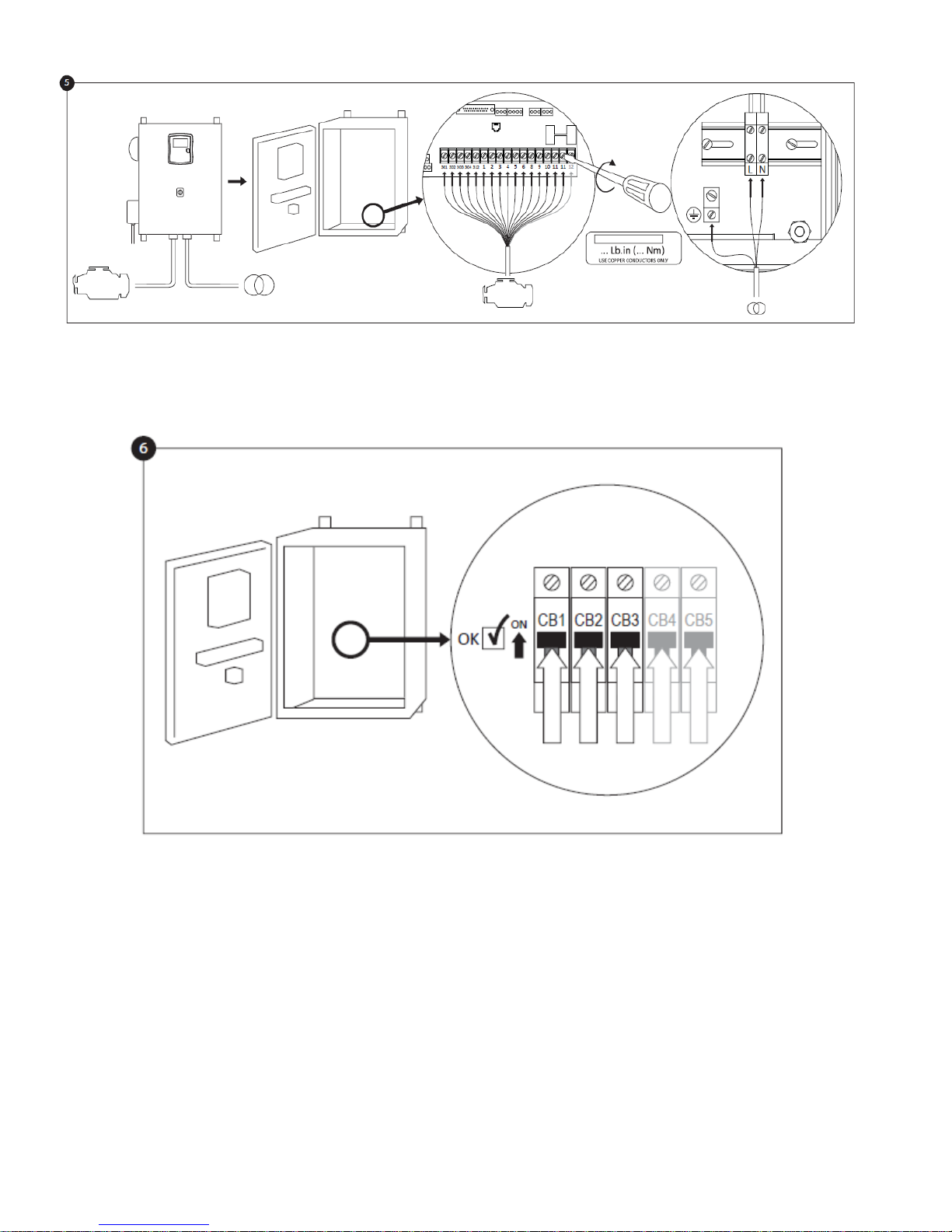
Connect all engine cables between the control panel and the controller engine terminals (Identified as “S” on the IO
board diagram that is displayed in the Terminal Strip Descriptions in the manual). Secure with the appropriate torque
as indicated on the torque label and verify all connections. Connect the AC main lines and ground to the AC
terminals in the controller.
Activate the disconnect switch (if present) and all breakers by setting them to the "on" position. The controller will
boot up for the first time.
11
Page 12
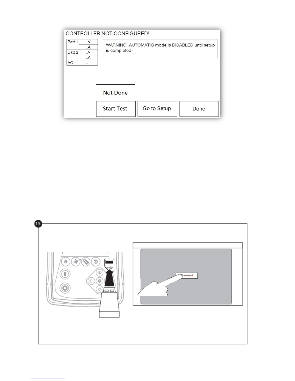
The “First Setup” page replaces the Homepage until the “First Setup” is done. Verify that the controller reads the
batteries voltage and current. Verify the “AC” is “OK” and not “FAIL”. Verify that the pressure reading is correct.
Before trying to start the engine, verify that the engine setup is complete and the exhaust pipe is connected properly.
Verify that the engine has started and is running properly.
Click on the “Go to Setup” button. The “Config” page is now visible. Click on the “padlock” button to log in with your
password. If needed, read the “User Login / KeyPad” section for more information on how to enter your password.
Once a valid password is confirmed, the “Config” page will be visible again with the “padlock” showing that it is open
the actual user security level.
Once the configuration is done, click on the “Home” membrane button. The “First Setup” page will be displayed
When satisfied with the controller settings, press the "Home" button on the membrane, acknowledge the changes by
pressing the done button. If the done button is unavailable, ensure that a sufficient authorization code has been
entered.
12
Page 13
Proceed with the download step to save the report.
Press the home page button to verify that the displayed values are correct.
The “First Start up” is now completed. The controller is fully installed and configured.
13
Page 14
The ViZiTouch
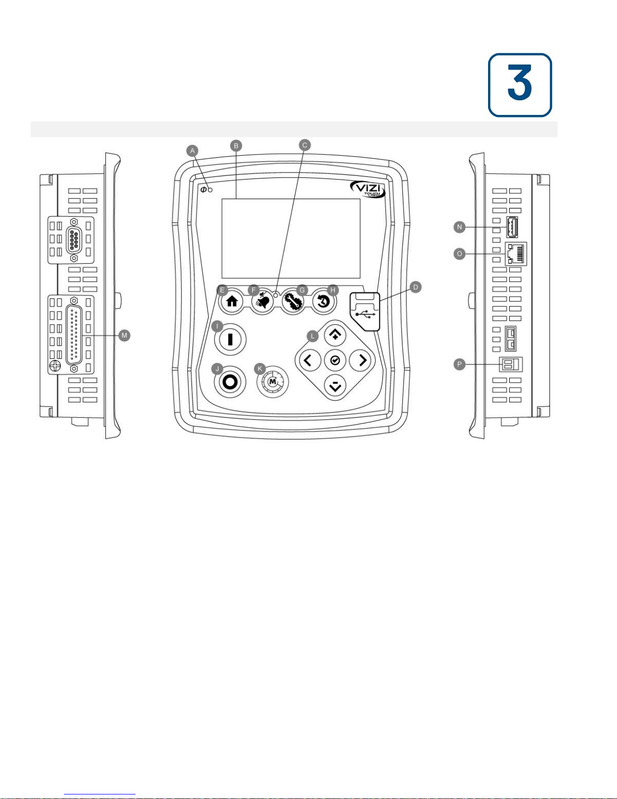
A: Power LED: Indicates if the ViZiTouch is properly powered.
B: Touch Screen: 4.2 inches color touch screen LCD.
C: Alarm LED: Indicates if an alarm is currently active.
D: Front USB Connector: USB Device connector used for file download, software updates, service reports.
E: Home button: Used to navigate to the Home page.
F: Alarm button: Used to navigate to the Alarm page. It also allows the user to silence the alarm bell, hence the
small "no speaker" symbol in the upper right corner of the button.
G: Config button: Used to navigate to the Configuration page.
H: History button: Used to navigate to the History page.
I: Manual Start button: Used to start the automatic cranking sequence.
J: Stop button: Used to stop the engine if all starting conditions are gone.
K: OPERATE START TEST PUSH BUTTON: The engine can be started by using this pushbutton after a "Fail to
Start" alarm, after an automatic start followed by a stop, and during the first setup procedure. The last method will
not activate the "Fuel Solenoid" relay, therefore creating an intentional "Fail to Start". This method of starting will
activate both cranking starters.
L: Contextual navigation pad: Used to facilitate the navigation on specific pages. A small icon representing the
contextual navigation pad will appear at the bottom right corner of a page if the pad is active. By clicking on the
small pad icon, a menu explaining the specific functions of the arrows will appear. For example, it is possible to
switch between the graphical or the table mode on the logs page, as well as navigate through the tables.
M: CAN bus connector to IO cards
N: USB 2.0 connector
O: Ethernet connector
P: Alarm Bell connector
Main Features
14
Page 15

Warning
After 2 years of service, the Vizitouch battery may become less efficient and could lose the time after a shutdown.
Alarm Bell
The alarm bell is activated under default faulty conditions and under optional or user defined conditions.
Any of these conditions will energize the alarm bell but may be silenced, by pressing on the “Alarms / Silence”
membrane button. When silenced, the alarm bell restarts ringing if a new fault occurs or if the alarm conditions
remain unchanged after 24 hours. The alarm bell automatically stops ringing if alarm conditions are not present
anymore.
Note: other external conditions may trigger optional conditions depending of the factory settings. Verify drawings
affixed inside the cabinet.
Default Conditions :
- Engine Overspeed
- Engine Low Oil Pressure
- Engine High Coolant Temperature
- Engine Fail to Start
- Battery Failure 1-2
- DC Failure
- AC Fail
- I/O Cards Communication Loss
- CAN System Failure
- File System Failure
First Setup
The First Setup must be done prior to using the controller. Completing the First Setup is the only way to access the
homepage and enable the automatic mode of the controller.
15
Page 16
Home (Membrane button)
Home
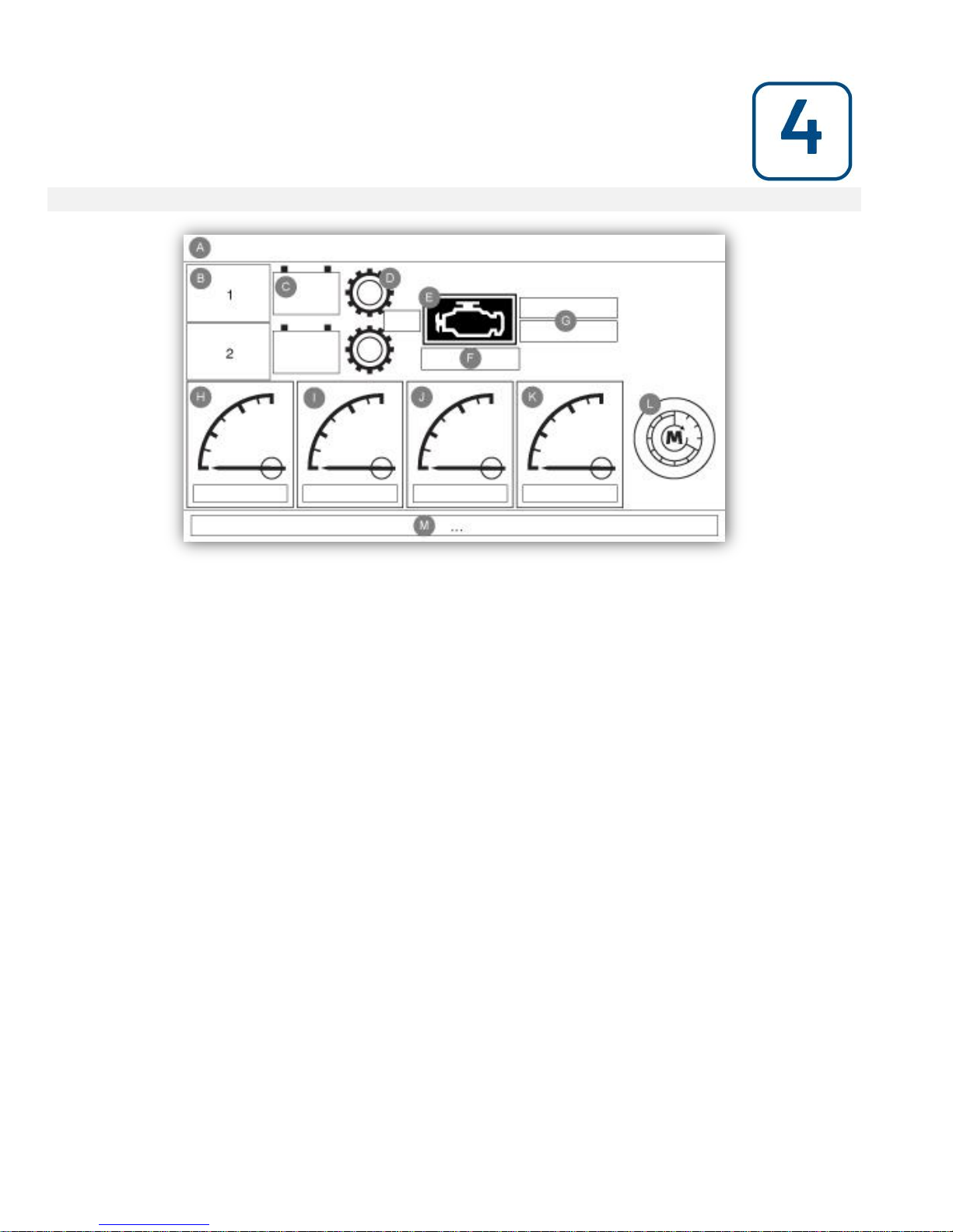
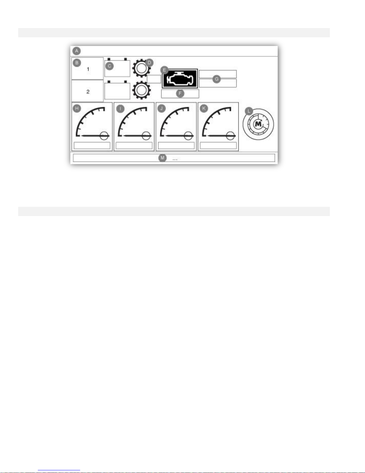
The home page displays all controller statuses and important values of the controller. All voltages, currents, engine
state and status, as well as all timers and cranking sequences.
The entire background will become red if an alarm becomes active. This feature will help the user identify a problem
even at a significant distance away from the controller.
A: Navigation bar which contains general information about:
- The language (the language may be changed by pressing on it)
- The page title
- The alarm banner (warning and alarm messages may be shown)
- The date and time (adjustable in the Configuration page)
B: Battery charger state. It may become one of three colors and also explicitly describes the current battery charger
state.
POWER UP – Green
BULK – Green
OVER_CHARGE – Green
FLOAT – Green
CHARGER_FAIL – Red
NO_AC – Red
BATTERY_FAIL – Green
An orange rectangle between the battery and the charger will appear periodically. It is the boost mode. This
charging mode enables the boost function on the charger, allowing a shorter charging time of the battery. Also, it
allows the controller to detect a missing battery, and/or a problem with the charger.
C: Battery. The battery will be red if it is in failure and green otherwise. The first line of data shows the actual
voltage of the battery in volts and the second line shows the actual current in amperage.
Home
16
Page 17

D: Starter gear. It represents the current step of the cranking sequence. The counter inside indicates the step
remaining time, counting down from 10 to 0 seconds. As there are two cranking modes, "waiting for crank" and
"cranking", the gear will alternate between yellow and green, allowing the user to know exactly the state of the
cranking sequence. Between the two contactors, a counter is visible. It indicates the current step inside the cranking
sequence. It will stay on a step during the 10 seconds of wait and on the 10 seconds of cranking and then will count
on until the sixth step, which is the end of the cranking sequence.
E: Diesel engine. It will be grey if the engine is stopped, green if an "Engine Run" signal is detected and red if an
"Overspeed" or "Fail to start" occurred, after 6 unsuccessful cranking attempts. The engine will be yellow if running
in test mode.
F: Representation of the motor starting or stopping cause. A green capsule will indicate the reason why the engine
is running, and a red capsule will indicate reason it is not running when it should. Possible choices are:
Local – Optional: This start cause is triggered if the engine is locally started directly from its own control panel and
the option is enabled.
Manual – It receives a manual crank request from one or both of the manual crank membrane buttons while the
selector switch is the "HAND" position.
Emergency – It receives a manual crank request from the emergency pushbutton.
Remote manual: Manual engine starting activated by a remote start contact.
Deluge: Automatic engine starting activated by a deluge valve.
Remote auto: Automatic motor starting activated by remote equipment
Alternative current failure – Alternative current failure will count the time following an AC Failure and at the end of a
predetermined timer, will start the engine with an Alternative current failure request when this option is enabled.
A red capsule will indicate the reason why the motor is not running despite the fact that a request is being made.
Possible causes are:
Fail to start – This failure happens when the controller receives a request to start, but a "Fail To Start" alarm is
active after a cranking sequence failure, thus preventing its ability to effectively start the engine until this alarm is
reset.
Locked: An interlock signal is preventing the motor from running.
G: Operations timers including the sequential start timer and the AC Fail timer.
H, I, J, K: Please refer to chapter 6 "Configuration", the section on the sensors for detailed information on the
gauges.
L, M: The "M" section shows the text: "Operate manual start test push button". It is grey when the corresponding
button is offline. When the button becomes active, the message color turns Yellow, and the button''s logo appear on
screen ("L"), sending the message that the controller is ready for this test.
Screen Saver
After 5 minutes of inactivity on the ViZiTouch, the screen will dim it's brightness to 25%. After 10 minutes of
inactivity on the ViziTouch, the “Black Screen” screen saver will activate. Its goal is to expand the lifetime of the
LCD screen. The screen saver will be instantly deactivated if the engine is running or if an alarm is activated. To
manually deactivate it, simply touch the screen or any membrane button. After deactivation, the screen saver will
always redirect to the “Home” page. It will also log off any user by resetting the security level to 0 and save any new
modifications to the settings.
17
Page 18
Alarms (Membrane button)
Alarms
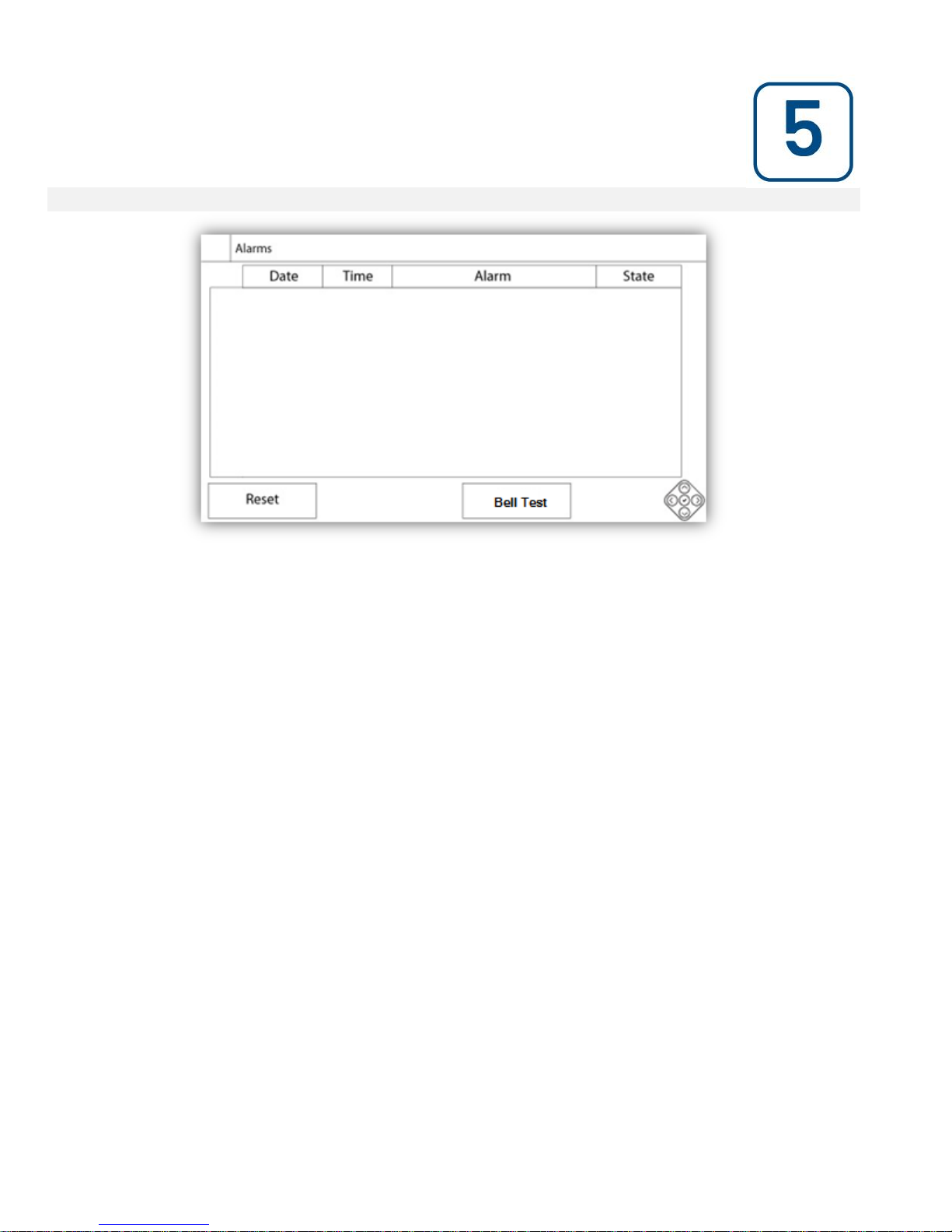
Displays the list of currently active and occurred alarms. An alarm is called ACTIVE when its triggering condition is
present. An alarm is called OCCURED when its triggering condition has been active, but is no longer true. Alarms
representing serious concerns are RED. Alarms representing simple warnings are YELLOW. To silence the bell
press the ALARM button or it will silence itself after the expiration of a factory set timer. Pressing on the RESET
button will reset OCCURED alarms only.
The bell test button will activate the alarm bell for 3 seconds.
The table displays system events:
- Date and Time: Date and time stamp of the alarm in the YYYY.MM.DD format
- Message: Alarm message
- State: OCCURED or ACTIVE
- Color Code:
- Red: The event is an alarm
- Yellow: The event is a warning
Complete list of alarms :
Common Alarms:
Engine Trouble: The Engine Trouble common alarm is active when one or more of these conditions are active :
- Engine High Coolant Temperature
- Engine Low Coolant Temperature
- Engine Low Oil Pressure
- Engine Fail to Start
- Engine Overspeed*
- Battery Failure 1-2
Pump Room Trouble: A common alarm activated when the following events occur:
- Fuel Tank Leak
- Low Fuel Level
- High Fuel Level
- AC Failure
- Water Reservoir Low
- Water Reservoir High
- Water Reservoir Empty
Alarms
18
Page 19

CTRL Trouble: Important: this relay is normally energized when controller is in normal condition. The relay is deenergized when controller trouble is detected (fail safe). The controller trouble common alarm is active when one or
more of these conditions are active :
- Charger Failure 1-2
- DC failure
- AC Failure: Monitors the AC power and activates on a failure.
- Battery 1-2 Fail: Monitors the status of battery 1 and activates on a failure. This occurs when the battery is
disconnected, is the wrong type or is unable to be recharged. When disconnecting a battery, there will be a delay
before the alarm is activated. The boost signal will be active a minute later, or more if a ghost current is detected. If
there is no response from the battery, it will execute a second test 30 seconds later, and then activate the battery
failure alarm.
- Charger 1-2 Fail: Monitors the state of battery charger 1 and activates on a failure. This occurs when the battery
charger has a defect, is not properly powered, or is unable to provide the needed current. It will also change to
Boost Fault mode if during a boost test, the voltage does not rise. A NC dry contact is also connected from the
charger to the I/O Board. If this contact opens for 1 minute, the alarm will be activated. Chargers readings are not
updated during cranking and/or running, due to reading instability under load. As soon as the engine returns to an
idle state, all readings and failure analysis are reactivated.
(Note: With the option NiCad batteries, no boost is used and there is no NC dry contact. The "Charger Fail" alarm is
detected when the battery voltage goes under the float voltage and no current is detected between the charger and
the battery.)
- Loss of Continuity 1-2: Activates if the engine start contactors are disconnected from the controller.
- Water Res. Low: Activates if the “Water Reservoir Low” contact input is triggered or if the analog readout of the
water reservoir is enabled and is lower than the water reservoir low set point in the “Water Level” sensor page.
- Water Res. Empty: Activates if an external contact triggers the optional “Water Reservoir Empty” input.
- Main Relief Valve Open: Activates if an external contact triggers the optional “Main Relief Valve Open” input.
- Fuel Tank Leak: Activates if the “Fuel Tank Leak” contact input is triggered.
- Low Fuel Level: Activates if the “Low Fuel Level” contact input is triggered or if the analog readout of the fuel level
is enabled and goes lower than the low fuel level set point in the “Fuel Level” sensor page.
- High Fuel Level: Activates if the “High Fuel Level” contact input is triggered or if the analog readout of the fuel
level is enabled and goes higher than the high fuel level set point in the “Fuel Level” sensor page.
- Engine Fail When Running: Activates if the “Engine is running” signal is lost while the engine is running. The
engine will try to start the cranking sequence once again if the starting causes are not back to normal.
- Engine Fail to Start: Activates if the engine fail to start after the complete 6 attempts crank sequence. The engine
will turn red.
- Engine High Temperature: Activates if the specific “High Temp” input is triggered on the engine connector strip
and the engine is running. This alarm will stop the engine only if triggered during a manual run test.
- Engine Low Temperature: Activates if the specific “Low Temp” input (15) is triggered on the engine connector
strip.
- Engine Low Oil Pressure: Activates if the specific “Low Oil Pressure” input is triggered on the engine connector
strip and the engine is running. This alarm will stop the engine only if triggered during a manual run test.
- Engine Overspeed*: Activates if the speed read is higher than the set Overspeed value and the engine is running.
This alarm will stop the engine only if triggered during a manual run test.
19
Page 20

- I/O_expX-inX alarm: Activates if the specific expansion programmable input on the specific expansion board is
activated and triggered.
- Battery1-2 Overvoltage: Activates if the voltage of the specific battery is higher than the specified overvoltage set
point.
- I/O Diesel Communication Error: Activates if no communication with the diesel I/O board could be established for
15 seconds. This alarm is critical and triggers the bell. If this alarm persists for more than 1 minute the controller will
reboot to try and fix the problem.
- I/O Expansion Communication Error: Activates if no communication with the Expansion I/O board could be
established for 15 seconds.
- Communication System Failure: Activates when the communication task has stopped responding. This alarm
condition is critical and will be followed by a controller reboot to try and fix the problem.
- File System Failure: Activates when a file system error is detected. This alarm condition is critical and will be
followed by a controller reboot to try and fix the problem.
20
Page 21
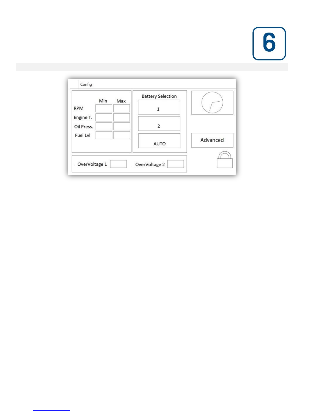
Config (Membrane button)
Config
Setup all basic configuration parameters.
The main configuration page provides a quick means of changing the most common settings. The padlock icon
indicates the current authorization level. A locked padlock indicates that only basic settings can be changed. Press
on the padlock to enter an authorization code to unlock additional settings. An unlocked padlock showing an
authorization number indicates that some settings are unlocked. Press on the padlock again when you have
concluded your operation.
Access Level 0:
- The “Advanced” button activates the advanced configuration pages.
- Date and Time adjustment are accessed by pressing the clock. Refer to the “Date and Time” page for more
information.
Access Level 1:
Inside the left box, the engine speed parameters can be set. Adjustment of the Minimum and the Maximum of the
speed gauge displayed on the Homepage.
Inside the middle box, a battery selection can be made. This setting should always be “AUTO”, unless if doing
maintenance on one battery or for testing purposes.
Inside the lower box, two “overvoltage” set points can be adjusted to trigger battery Overvoltage alarms.
Configuration
21
Page 22
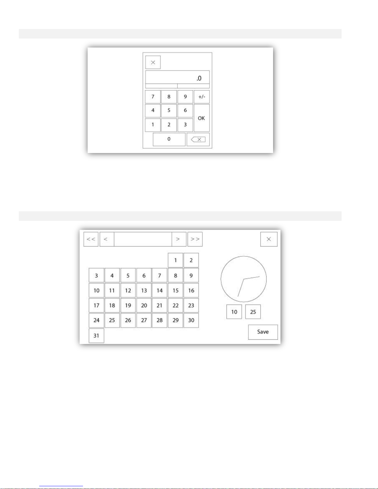
NumPad Page
The NumPad is activated every time the user clicks on a white square box representing a number that can be set.
On top of the NumPad, the current parameter is shown. The text will flash red if the value entered is invalid and the
OK button will be black, indicating that the value is out of range. The MIN and MAX show the range of values
accepted for that particular parameter. The “X” button allows the user to cancel editing the value. The back arrow
erases the last entered number and the “CA” button clears the whole text field. Simply click the “OK” button once
the value is set.
Date and Time Page
22
Page 23
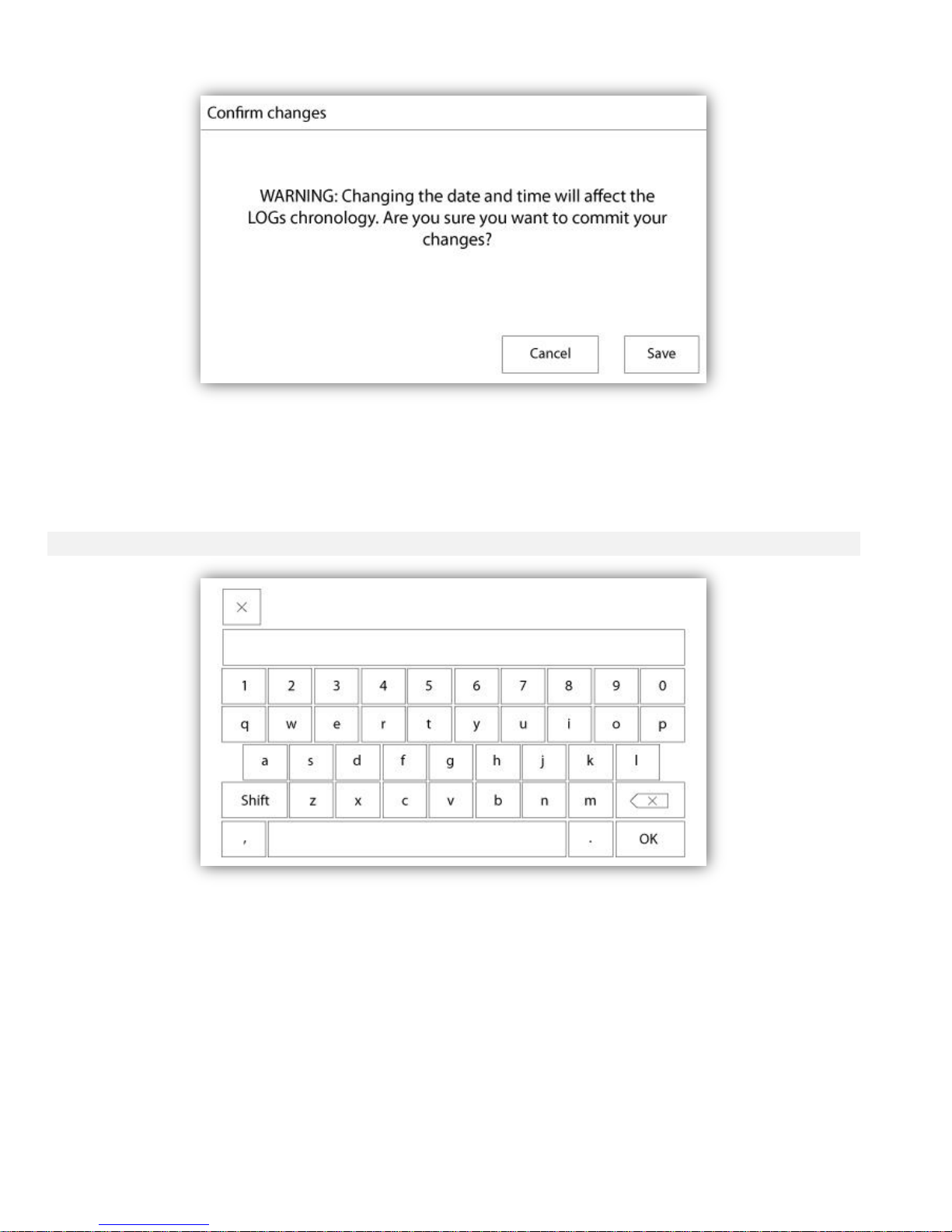
The Date and Time can be configured by selecting the current month and year by pressing the arrow buttons on
each side of the “Month-Year” display and selecting the day of the month by selecting the actual day. The time is
set by pressing the two square boxes under the clock; the left sets the hours and the right sets the minutes. Press
the Save button to commit the changes. A dialog box will appear to confirm the change “Date and Time”. The user
may cancel the changes by pressing the “Cancel” button. Please note that changing the date and time will have an
effect on the logs chronology.
User Login Page / KeyPad Page
User Login KeyPad:
This page allows the user to log into a higher security level by entering a password. If the password is valid the text
field will turn green and if it is invalid, the text field will turn red. A "X" button appears in the text field as soon as a
character is entered, allowing for a quick erase of the written password.
If the password is invalid for a consecutive number of times, the user will be redirected to the "Service Dealer"
page, allowing the user to communicate with the appropriate Service Dealer.
If the password is valid, the "Configuration" page will reload and the access security level will be shown inside the
lock. To log off, click on the lock and the user security level will return to "0"
Other KeyPads:
The KeyPad is activated every time the user clicks on a grey rectangle box with white text representing a text that
can be set. The "X" button allows the user to cancel editing the value. The back arrow erases the last entered
23
Page 24
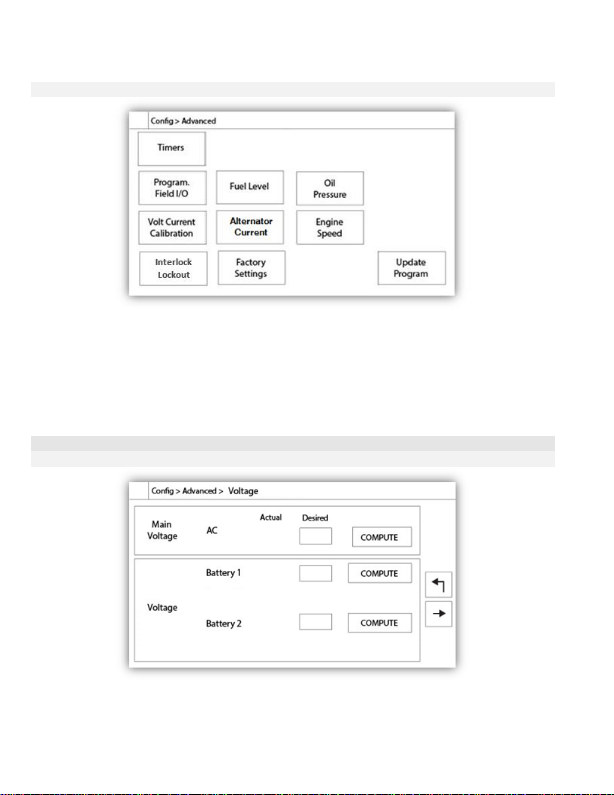
character and the "CA" button clears the whole text field. Simply click the "OK" button once the value is set. This
type of text field is mostly used to generate a digital text indication for a custom alarm input.
Advanced Configuration Page
Config > Advanced
This page is the portal to all the advanced configuration parameters of the ViZiTouch.
All timers, sensors, factory settings, software update, service dealer and debug pages may be accessed simply by
clicking on the appropriate buttons.
Since two of the analog inputs are using the same physical connector, only one of these can be installed at once.
These analog inputs are shown in the grey box surrounded by a black dotted line. Each time one of these sensors
is installed, the other will turn orange, preventing the dual installation of these sensors.
All buttons are set to security "Level 0" except "Update Program" which is set at "Level 1" security.
Details of the Advanced Configuration Page
Volt-Current Calibration
Config > Advanced > Calibration Voltage-Current
This page is used to calibrate all analog voltages. The actual column shows the actual value calculated by the
ViZiTouch. The “desired” column allows a level 2 user to enter the desired value read from a calibrated external
device (multimeter). For the AC voltage and the 2 DC voltage, the calibration is done by entering the desired value
and pressing on the “COMPUTE” buttons. The DC values must be entered with no batteries connected, to allow the
24
Page 25
calibration of the battery chargers in the “power supply” mode. To do so, simply turn the batteries circuit breaker to
OFF.
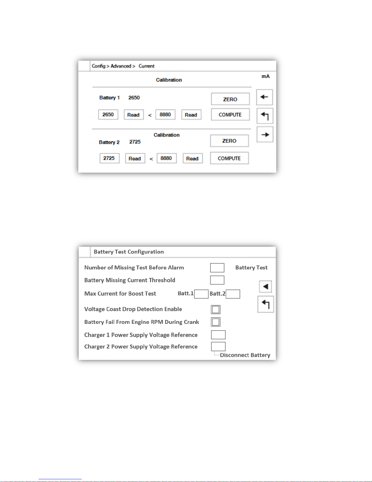
This page is used to calibrate all analog currents. The first number right beside the Battery 1 and Battery 2 text
shows the actual current reading. First, Set the CB3 Breaker in the OFF position. This will disconnect the battery.
Press the ZERO button. Then, put the CB3 breaker back in the ON position. Connect a small charge to the 6 and
11 terminals, to create a low current around 2600 mA. Enter this value in the most left field of battery 1, and press
the Read button. Then, connect a bigger charge to the 6 and 11 terminals, around 8800 mA. Write the measured
value in the second text field, and press the second read button. Finally, press the COMPUTE button to complete
the calibration. Repeat for the second battery, linked to CB4 Breaker and terminals 8 and 11.
This page is used to adjust the calibration of the battery test.
Number of Missing Test Before Alarm : It is the number of consecutive fail test that must occurred before triggering
the Battery Failure alarm.
Battery Missing Current Threshold : It is the threshold, in Amps, to test if a battery is connected. This is the amount
that the current in Amps has to rise during a boost test to determine that the battery is connected. If a false battery
failure alarms appears, it may be necessary to lower this value.
Max Current for Boost Test : Under this current value in Amps, no test on the battery is made.
25
Page 26
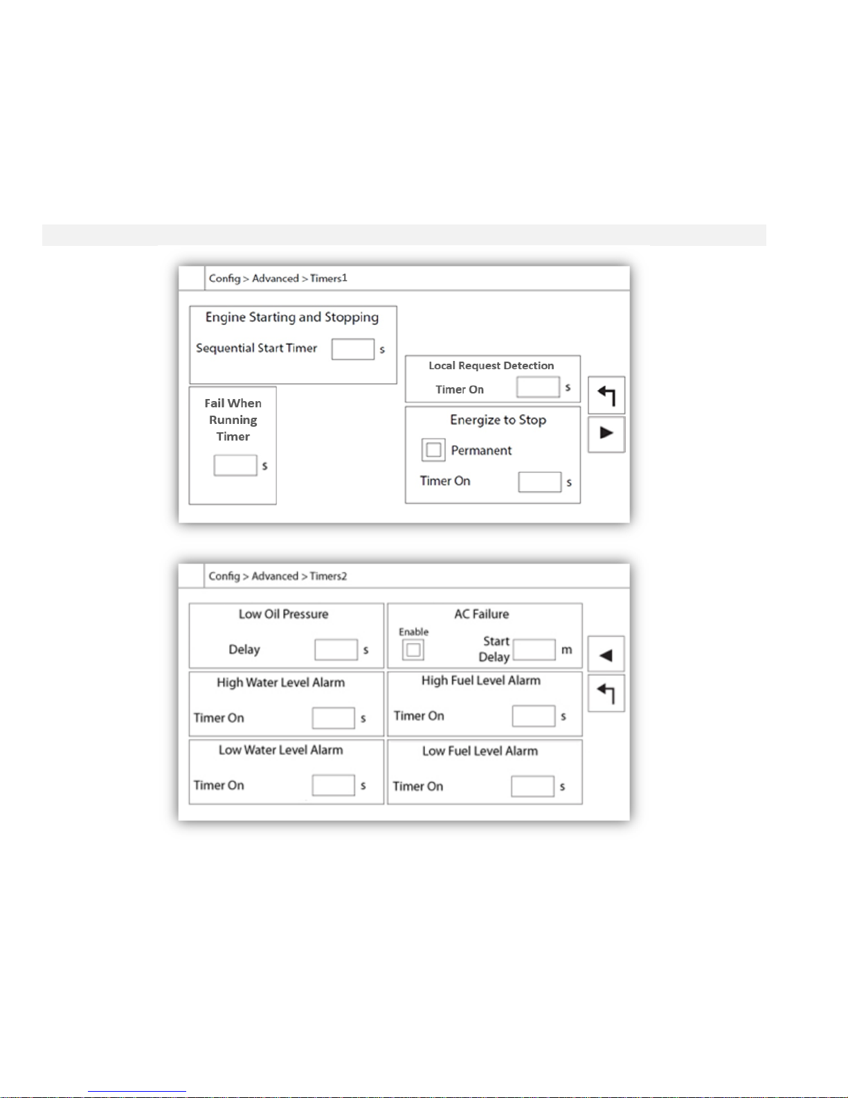
Voltage Coast Drop Detection Enable : If enable, this second condition on the battery test is activated. On smaller
battery, the rise in current during a boost test might be to small to have a conclusive test. This second test verify the
capacitive effect on the battery line after a boost sequence.
Battery Fail From Engine RPM During Crank : If enable, the Battery Fail alarm will be activated if no RPM is read
after a crank cycle
Charger 1-2 Power Supply Voltage Reference : This is the voltage that is applied by the battery charger in power
supply mode (no battery connected). To measure this voltage, the battery must be disconnected.
Timers Page
Config > Advanced > Timers1-2
Most common timers for fire pump control can be configured here. Note that any timer set to 0 will remove the delay
in the decision process.
Access level 1:
- Engine starting and stopping:
The “Sequential Start Timer” allows a delayed response on an automatic start request.
- Energize to Stop:
This timer set the time in second the fuel solenoide valve will close after a stop.
- Fail When Running Timer:
26
Page 27
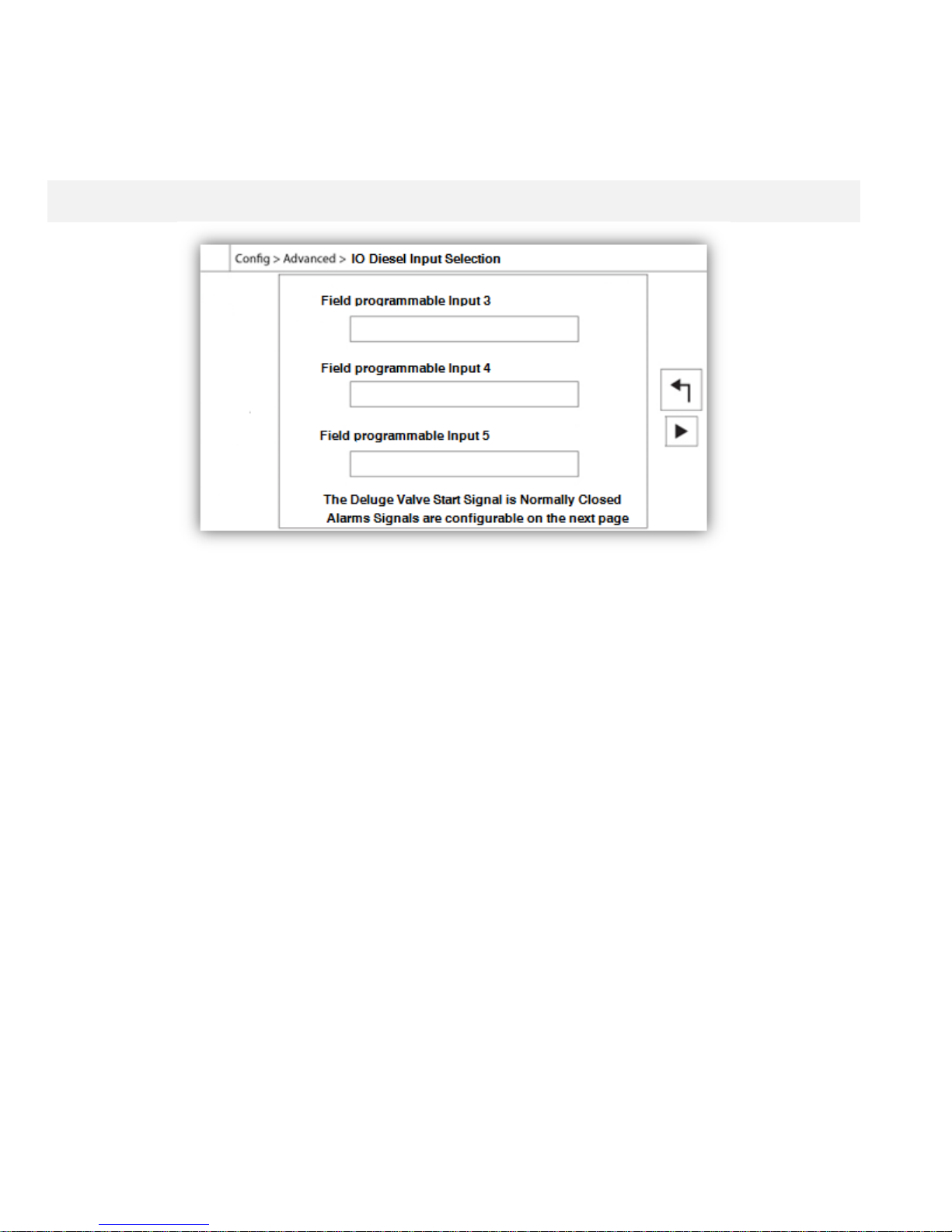
If Enabled, this timer will delay the "Fail When Running Alarm".
- Local Request Detection:
This is the delay it will take to the controller to detect a Local start of the pump.
The other timers are self explanatory and set the time delay on alarms.
Inputs/Outputs Configuration
Config > Advanced > IO Diesel Input Selection -
Config - Output Config
This page, if logged in, allows the re-assignation of 3 programmable inputs by pressing on the signal name. If the
Deluge Valve signal is selected, it will be assigned as a normally closed input. Proceed with caution as this may
cause the engine to start. If an alarm signal is chosen, it can be configured on the next page (Enabled, NO/NC,
Audible, Importance (Alarm or Warning). The available signals are:
- Low Fuel Level, High Fuel Level, Fuel Tank Leak
- Water Reservoir Empty, Water Reservoir Low, Water Reservoir High
- Flow Meter ON, Main Relief Valve Open
- Low Suction Pressure
- Lockout
- Remote Manual Start
- Deluge Valve Start (NC)
27
Page 28
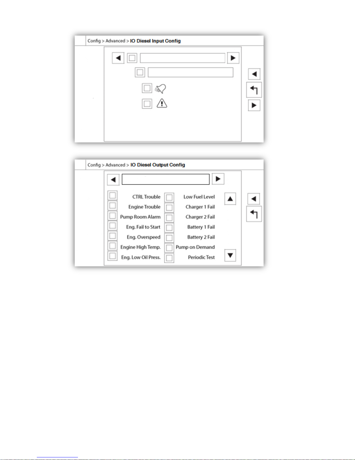
This page allows the configuration of alarm signals on the inputs, and outputs relay signals. Two buttons located far
right navigates between the input and output section of the page.
Input:
The input page has four elements: The NO/NC setting, the “Digital Text Indication” field, the “Alarm Bell Icon” and
the “Alarm Icon”. Each one can be enabled or disabled. The first step is to click on the square button beside the text
field to activate the management of the input signal. If the “Alarm Bell Icon” is enabled, the input signal will trigger
the Alarm Bell. If the “Alarm Icon” is enabled, the input signal will be treated as an alarm, if not, as a warning. As on
the output page, the buttons at the top allow for an easy navigation between all available inputs of the diesel board.
Output:
The configuration is performed by pressing on the square box located beside one of the signal needed. The box
will swap between BLANK (none), a NO (normally open) and a NC (normally close) symbol, allowing the desired
configuration to be obtained. The final state of the output signal is a logical “OR” combination of all selected signal.
28
Page 29
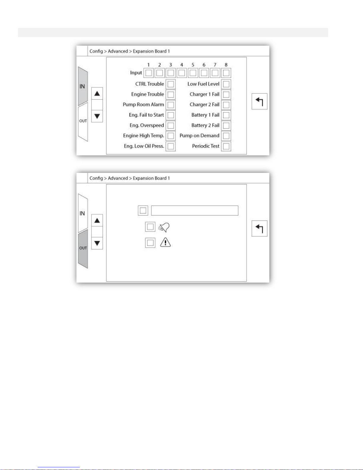
Inputs/Outputs Expansion board 1-2-3-4
Config > Advanced > Expansion Board 1-2-3-4
This page allows the configuration of both programmable inputs and outputs available on an IO Expansion board.
Two buttons located far right navigates between the input and output section of the page.
Input:
The input page has four elements: The NO/NC setting, the "Digital Text Indication" field, the "Alarm Bell Icon" and
the "Alarm Icon". Each one can be Enabled or disabled. The first step is to click on the square button beside the
text field to activate the management of the input signal. If the "Alarm Bell Icon" is Enabled, the input signal will
trigger the Alarm Bell. If the "Alarm Icon" is Enabled, the input signal will be treated as an alarm, if not, as a
warning. As on the output page, the buttons at the top allow for an easy navigation between all available inputs of
the diesel board.
Output:
The configuration is performed by pressing on the square box located beside one of the signal needed. The box will
swap between BLANK (none), a NO (normally open) and a NC (normally close) symbol, allowing the desired
configuration to be obtained. On top of all outputs signals available, it is possible to link in the same way the
expansion board inputs to the selected output in any combination. The final state of the output signal is a logical
"OR" combination of all selected signal.
29
Page 30
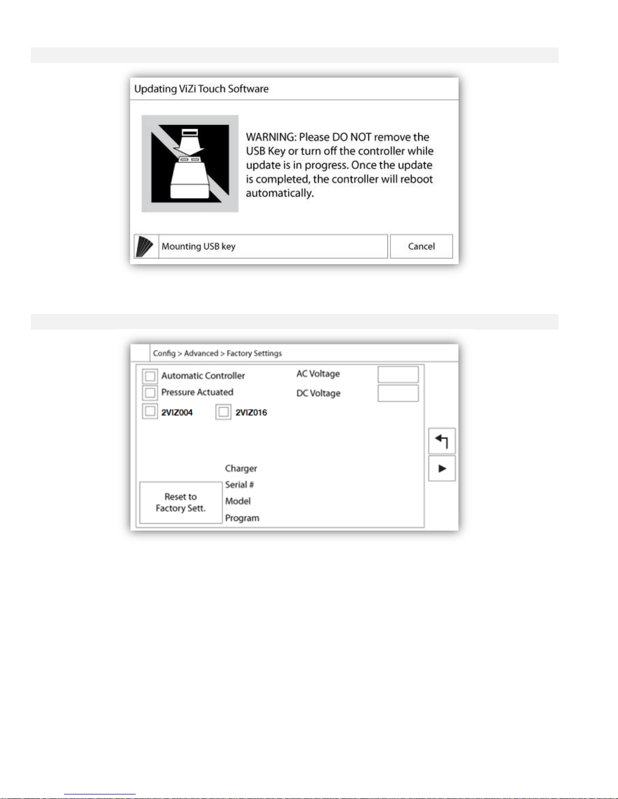
Update Program Page
This procedure is highly important and must be attempted with care. Please make sure to contact the factory prior
to using the Update Software function.
Factory Settings
Config > Advanced > Factory Settings
This page is only avalable if one or more Expansion Board is installed as an option.
The factory settings are always pre-configured at the factory and set the main parameters of the controller.
Left Section:
Automatic Controller – Non-Automatic Controller: An automatic controller will respond to automatic start requests,
like a pressure drop announced by a pressure transducer or a pressure switch, a deluge valve signal or a remote
automatic start trigger. A non-automatic controller will only start the engine on manual requests.
2VIZ004 – 2VIZ016: These refer to older version of the IO Diesel Board. If the controller hosts one of these version,
the corresponding check box must be activated.
“Reset to Factory Settings”: This button redirects to the “Reset to Factory Settings” page. This is a major operation
that must be used with care and only if the factory was contacted first. See the “Reset to Factory Settings” help for
more details.
30
Page 31
Right Section:
The first two settings set the nominal AC and DC voltage for the controller.
Technical information about the controller: Serial Number, Battery Charger Type, Model Name and Software
Revision.
Reset to Factory Settings Page
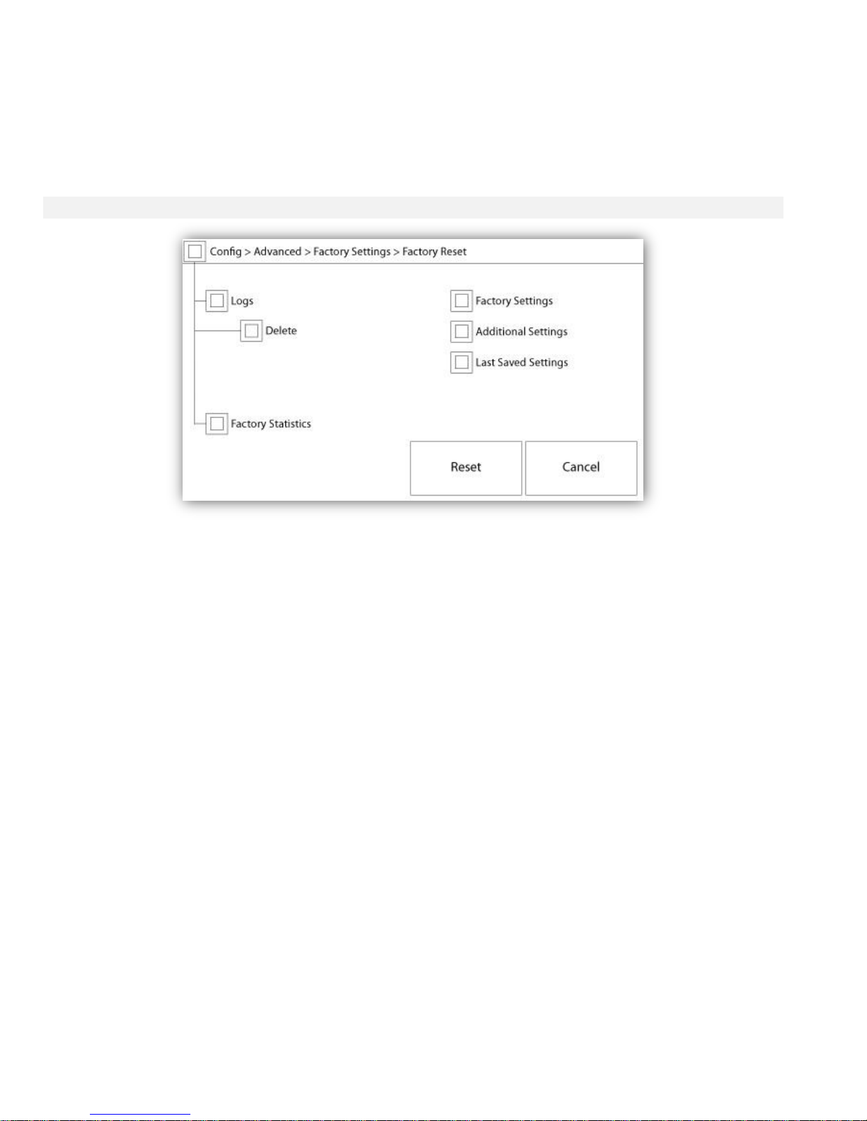
This page will reset the ViZiTouch to the original factory configuration, thus clearing all subsequent configurations
performed during the life of the controller.
This procedure should only be used as a last attempt to bring back the controller to a usable state.
User “Level 2”:
The “RESET” button will be activated (will become blue) only if no square buttons from the left column are activated
and the “Last Saved Settings” from the right column is not activated as well. A “Level 2” user can only reset the
“Factory Settings” and/or the “Additional Settings” from the right column.
The “Factory Settings” reset will restore the controller to its original factory configuration and service state. This
means that the first service will be undone, automatic mode settings, as well as the controller’s “Homepage” will be
deactivated until “First Service” is completed again. Please refer to the “Quick Start-Up” guide for more information
on how to perform the “First Start-Up” and how to complete the “Field Acceptance Test Report”.
Please note that all logs, pump curves and statistics will not be reset.
The “Additional Settings” reset will update the controller with an additional configuration sent by the manufacturer. It
does not perform a true “Factory Reset”. Its purpose is to allow an update of configuration variables that can only be
updated by Tornatech Inc.
All other square buttons on this page are “Level 9” security and can only be used by certified Tornatech
representatives, unless otherwise specified. The first square in the upper left corner performs the “Select all”
function for these parameters.
31
Page 32
The Sensors Pages
Important Notice!
Every analog sensor cable used for this controller should be shielded. The shield has to be grounded on the motor
side. Not complying to these recommendations may affect the controller good functioning and void its warranty.
H) Tachometer (Engine Speed Switch)
The tachometer (analog speed reading) gives the possibility to support engine with no electronic speed switch. The
magnetic pickup must be connected to the MP+MP- inputs on the I/O Board.
The first small green line and small red line on the gradations shows the Set point of the “Engine Run” Signal. When
the engine runs with a speed above this threshold, the ViZiTouch will consider it is running, and when it slows down
under the red line, it will be considered stopped. The second red line, usually set high on the gauge, represents the
“Overspeed” threshold. If the engine reaches that speed, the “Overspeed” alarm will be activated.
The rectangle box below the gauge is the odometer, showing the run time of the engine since the first startup.
Pressing on the gauge will bring the user to the “Config > Advanced > Engine Speed” page.
32
Page 33
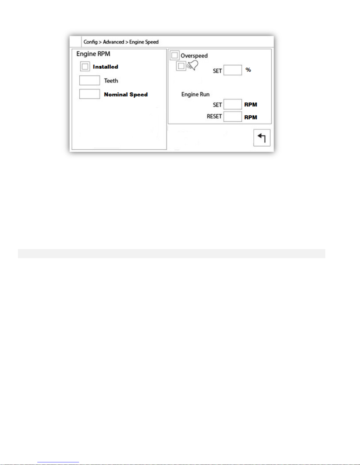
The left section is use to show the “Disable/Enable” state of the engine RPM Counter. The “teeth” input box allows
the user to match the number of teeth on the flywheel. This is an important setting to allow a precise calculation of
the RPM. The digital RPM value is shown just under to acknowledge the calculated RPM.
The right section’s purpose is to configure the set points of both “Engine Run” and “Overspeed” signal. The top
square box enables/disables the “Overspeed” alarm, and should always be activated. The following square box
links the alarm bell to the alarm, and the third one sets the signal category (alarm or warning). The “SET” input field
sets the trigger threshold for the “Overspeed” alarm. The next two input fields allows the configuration of the
“Engine Run” signal set/reset points, preventing the “Engine Run” signal to toggle too fast. “Reset” should be at
least 300 RPM lower than the “Set” point.
I) Engine Coolant Temperature
The “Engine coolant temperature” analog input gives the possibility to support engine with no electronic “Low-High
Engine Temperature” switch. The sender must be connected to the AI5 analog inputs on the I/O Board.
The first small green line and small red line on the gradations shows the Set point of the “Low Engine Temperature”
Signal. It is active if the temperature goes below the set point and the engine must not be running.
The second small green line and small red line on the gradations shows the Set point of the “High Engine
Temperature” Signal. It is active if the temperature goes above the set point and the engine must be running.
The rectangle box below the gauge displays the actual value.
Pressing on the gauge will bring the user to the “Config > Advanced > Engine Temperature” page.
33
Page 34
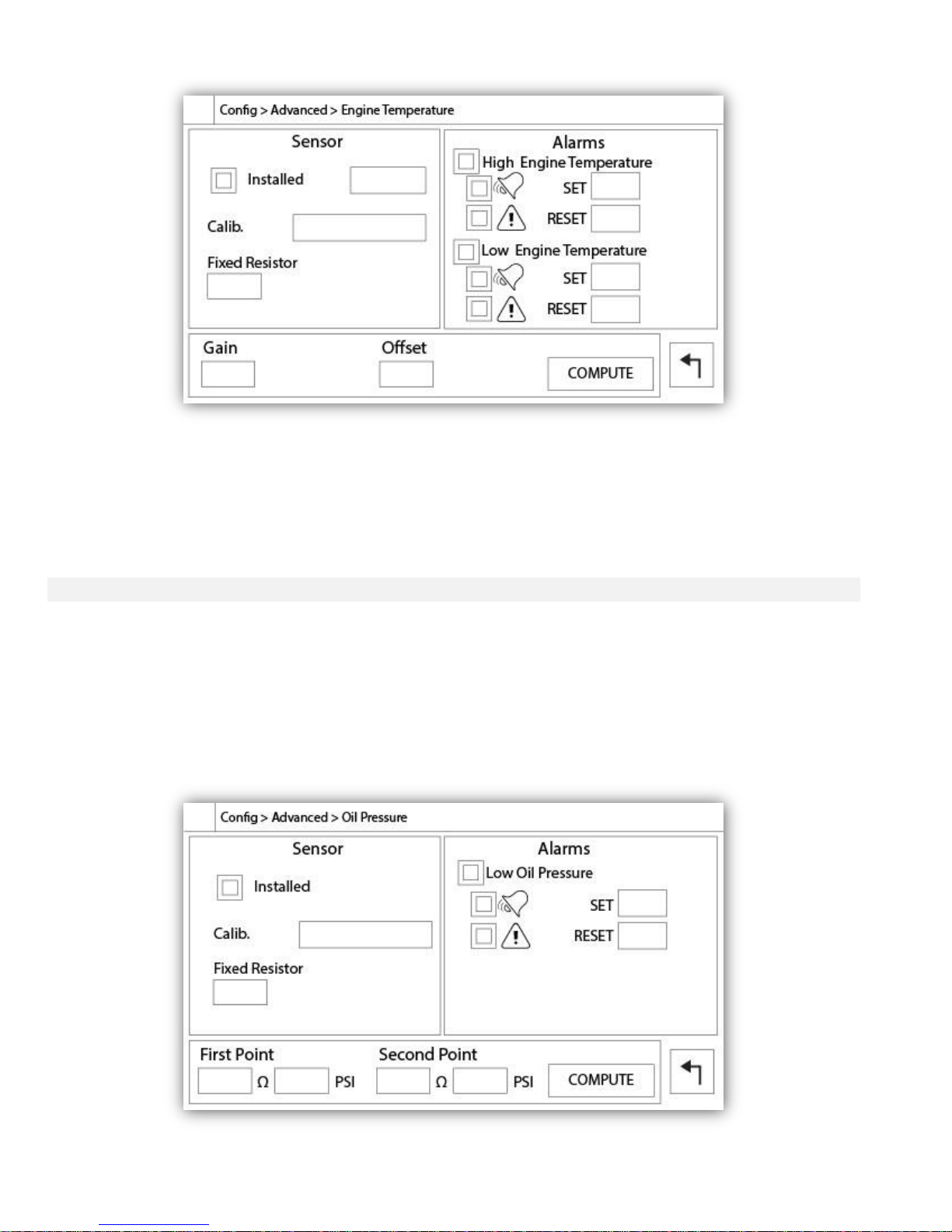
The left section is use to show the “Installed” state of the Engine Temperature Sender. The rest of the page is
already explained in the “Analog sensors” section of the manual.
If the “Calibration Type” is selected to be “Log. Resistor”, the bottom section will allow the user to directly change
the “Gain” and Offset” value, depending on the sender’s model. The “Fixed Resistor” value is linked to the hardware
resistor installed between the “+” and the “IN” inputs of the corresponding analog input.
J) Engine Oil Pressure
The “Engine Oil Pressure” analog input gives the possibility to support engine with no electronic “Low Oil Pressure”
switch. The sender must be connected to the AI3 analog inputs on the I/O Board.
The first small green line and small red line on the gradations shows the Set point of the “Low Oil Pressure” Signal.
It is active if the pressure goes below the set point and the engine must not be running.
The rectangle box below the gauge displays the actual value.
Pressing on the gauge will bring the user to the “Config > Advanced > Oil Pressure” page
34
Page 35
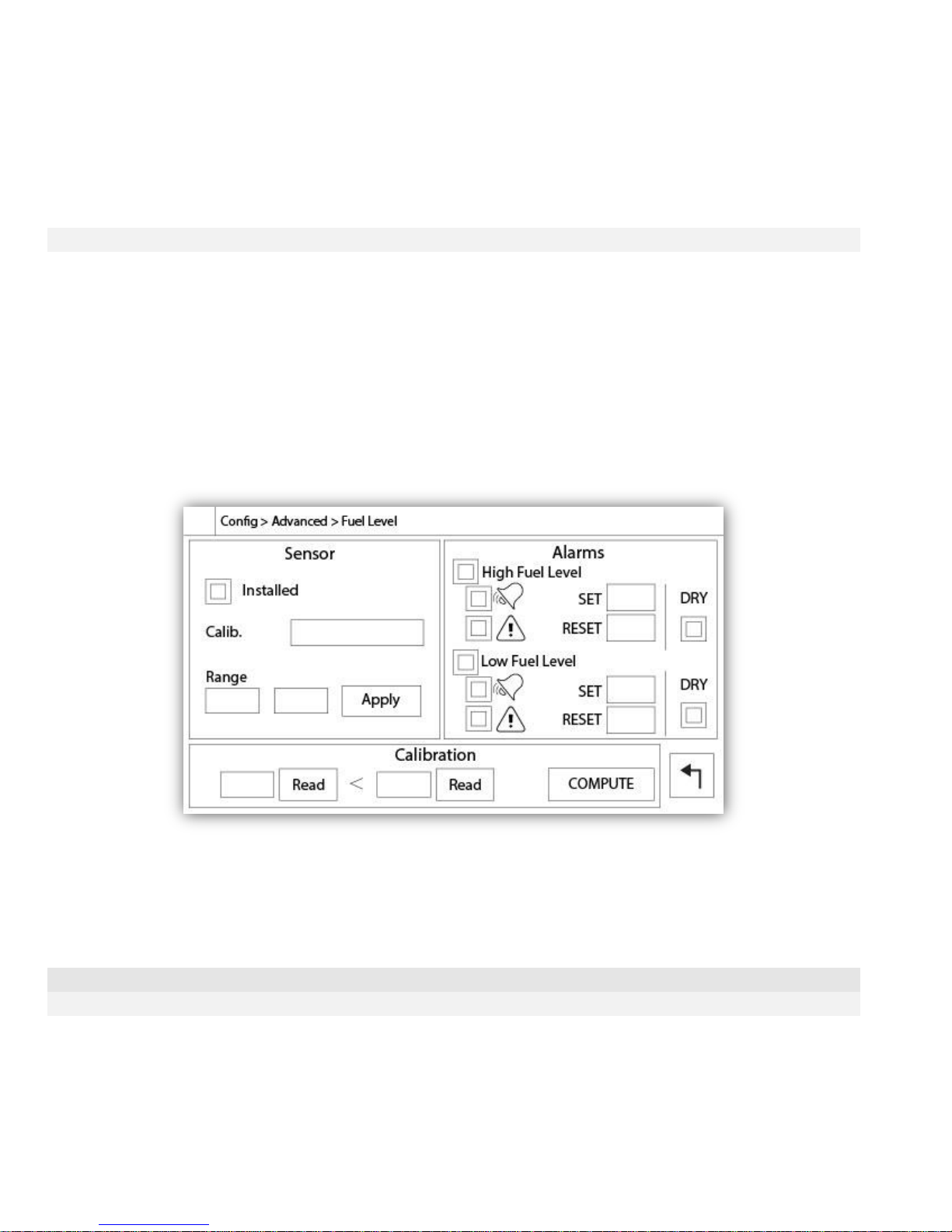
The left section is use to show the “Installed” state of the Oil Pressure Sender. The rest of the page is already
explained in the “Analog sensors” section of the manual.
If the “Calibration Type” is selected to be “Lin. Resistor”, the bottom section will allow the user to directly enters the
First point (resistor-pressure) and Second point (resistor-pressure) values, depending on the sender’s model. The
“Fixed Resistor” value is linked to the hardware resistor installed between the “+” and the “IN” inputs of the
corresponding analog input.
K) Fuel Level
The “Fuel Level” analog input gives the possibility to support engine with no electronic “Low-High Level;” switch.
The sender must be connected to the AI4 analog inputs on the I/O Board.
The first small green line and small red line on the gradations shows the Set point of the “Low Fuel Level” Signal. It
is active if the level goes below the set point.
The second small green line and small red line on the gradations shows the Set point of the “High Fuel Level”
Signal. It is active if the Level goes above the set point.
The rectangle box below the gauge displays the actual value.
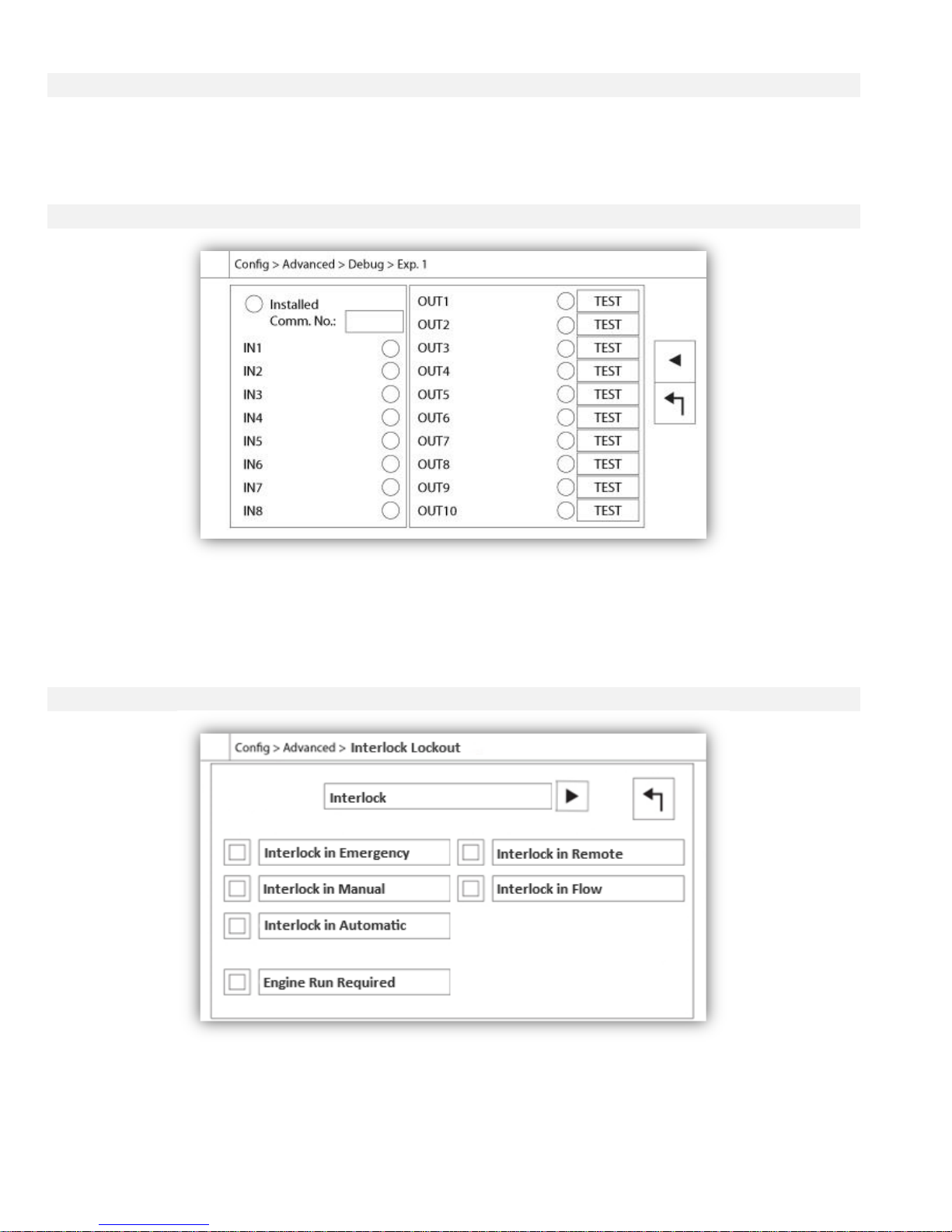
Pressing on the gauge will bring the user to the “Config > Advanced > Fuel Level” page.
The left section is use to show the “Installed” state of the Fuel Level Sensor. The rest of the page is already
explained in the “Analog sensors” section of the manual.
If the “Calibration Type” is selected to be “ON/OFF” (to be use with powered low fuel level switch), the frame at the
bottom of the page will be empty, and a “NO/NC” setting will be available to configure the signal.
Details of the Debug Page
Calibration
Config > Advanced > Debug > Calibration
This table displays all calibration parameters. The “Scaled” value is the final calculated value used in the ViZiTouch.
It is calculated by multiplying the “Raw” value by the “Gain” coefficient and by adding the “Offset” value. This
information is useful when debugging the analog inputs on the IO board.
35
Page 36
IO Debug
Config > Advanced > Debug > IO
The small white circle beside each signal is a representation of its state. If the white circle is filled with a green dot,
then the signal is activated. Comparing these software signals and the physical state of the signal on the electronic
board is the best way to troubleshoot. In the right column, additional “TEST” buttons are located beside each output
signal. Clicking on these buttons will toggle the output state of this signal, again allowing a comparison between the
software and hardware state of these signals to help troubleshoot.
Inputs/Outputs Debug
Config > Advanced > Debug > Expansion
The small white circle beside each signal is a representation of its state. If the white circle is filled with a green dot,
then the signal is activated. The first element in the left column is the indication of whether or not the optional
Expansion board is installed. In the box, the corresponding Expansion board number is displayed. Comparing
between these software signals and the physical state of the signal on the electronic board is the best way to
troubleshoot. In the right column, additional “TEST” buttons are located beside each output signal. Clicking on these
buttons will toggle the output state of this signal, again allowing a comparison between the software and hardware
state of these signals to help troubleshoot.
Interlock Lockout
Config > Advanced > Interlock Lockout
36
Page 37
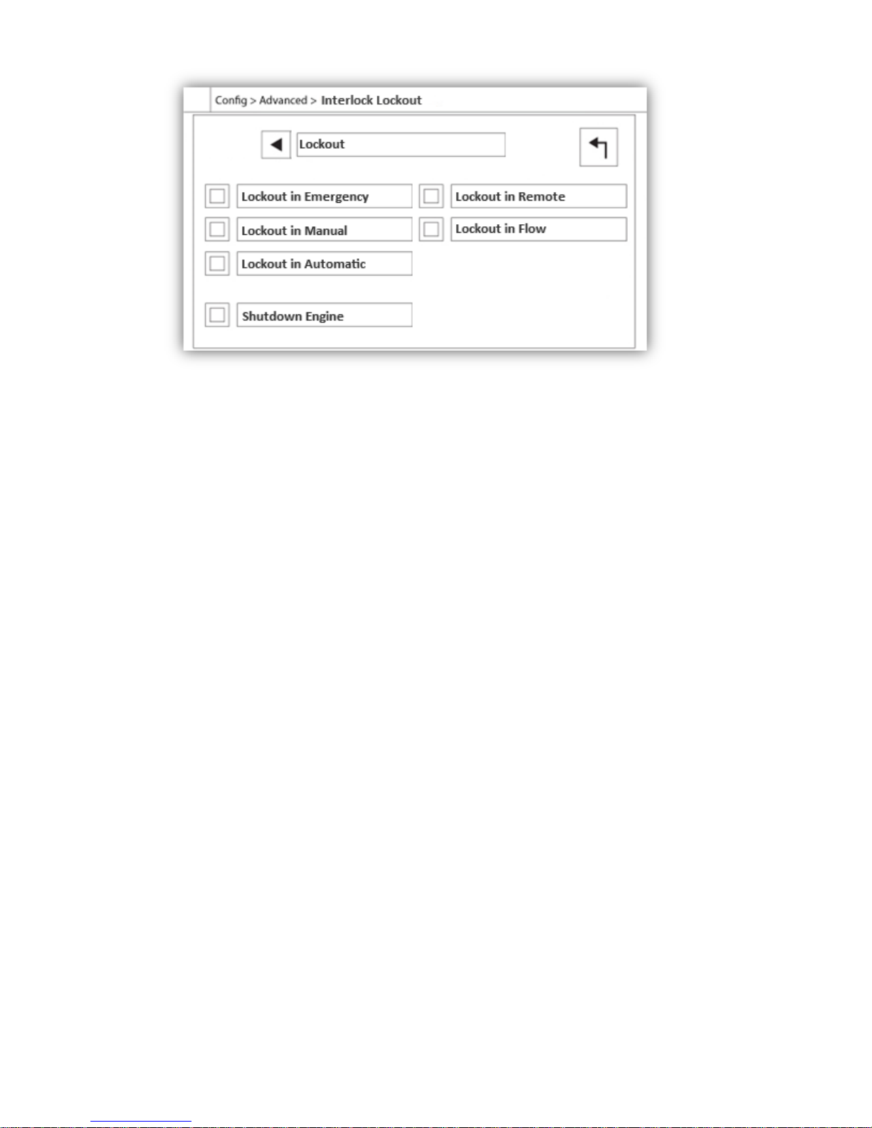
These pages allow to configure the Lockout input and the interlock output parameters. To be active, those options
need to be assigned to an Input or an Output on the I/O board.
Lockout is an Input that disables the engine from starting.
- Enable in emergency: If checked, this option will prevent the electronic assistance on an Emergency start.
- Enable in manual mode: If checked, this option will prevent the Manual start.
- Enable in automatic mode: If checked, this option will prevent the Automatic start.
- Enable in remote manual mode: If checked, this option will prevent the Remote Manual start.
- Enable in "start/stop" mode: If checked, this option will prevent the "start/stop" mode.
- Shutdown Engine: If enabled, the lockout signal will also act as a shutdown and will stop the engine if it is running.
Interlock is an Output that prevents a second engine from starting.
- Enable in emergency: If checked, this option will activate the output "interlock" on an Emergency start.
- Enable in manual mode: If checked, this option will activate the output "interlock" on a Manual start.
- Enable in automatic: If checked, this option will activate the output "interlock" on a Automatic start.
- Enable in Remote Manual mode: If checked, this option will activate the output "interlock" on a Remote Manual
start.
- Enable in "start/stop" mode: If checked, this option will activate the output "interlock" on a "start/stop" mode.
- Engine Run required: If enabled, the controller will wait to have the Engine Run signal before activating the
Interlock output.
37
Page 38
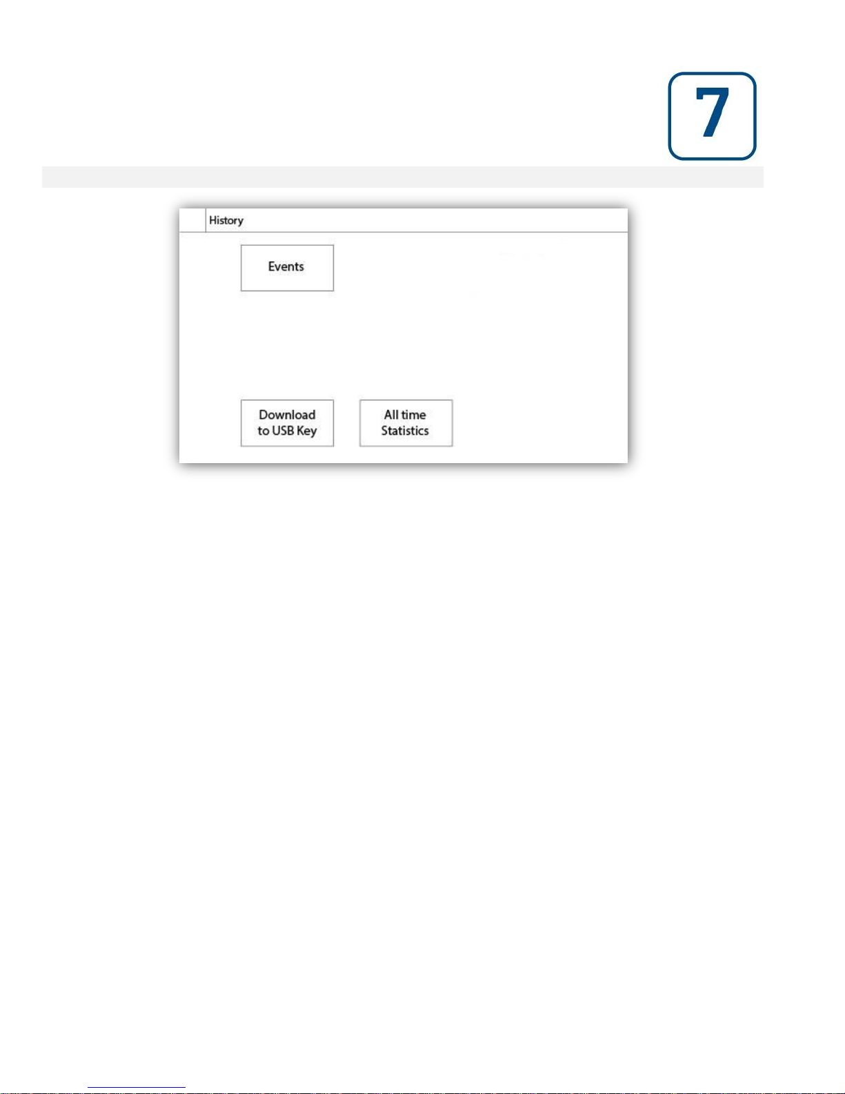
History (Membrane button)
History
Select specific pages within the History section. Everything related to the statistics, events, pressure, power logs
and the download to USB is available within the History page.
-Events: This button leads to the “Events” page, which displays the most recent 500 events. Each event log
contains the date and time of occurrence as well as a brief description of the event.
-Download to USB Device: This button leads to the “Download to USB Device” page, which allows the user to
download information, including the user manual, drawings, logs, statistics and configuration.
-All Time Statistics: This button leads to the “All Time Statistics” page, which displays the date and time of the first
power up, the date and time when the first start-up was completed and the total “On Time” of the controller. These
statistics can never be reset.
History
38
Page 39
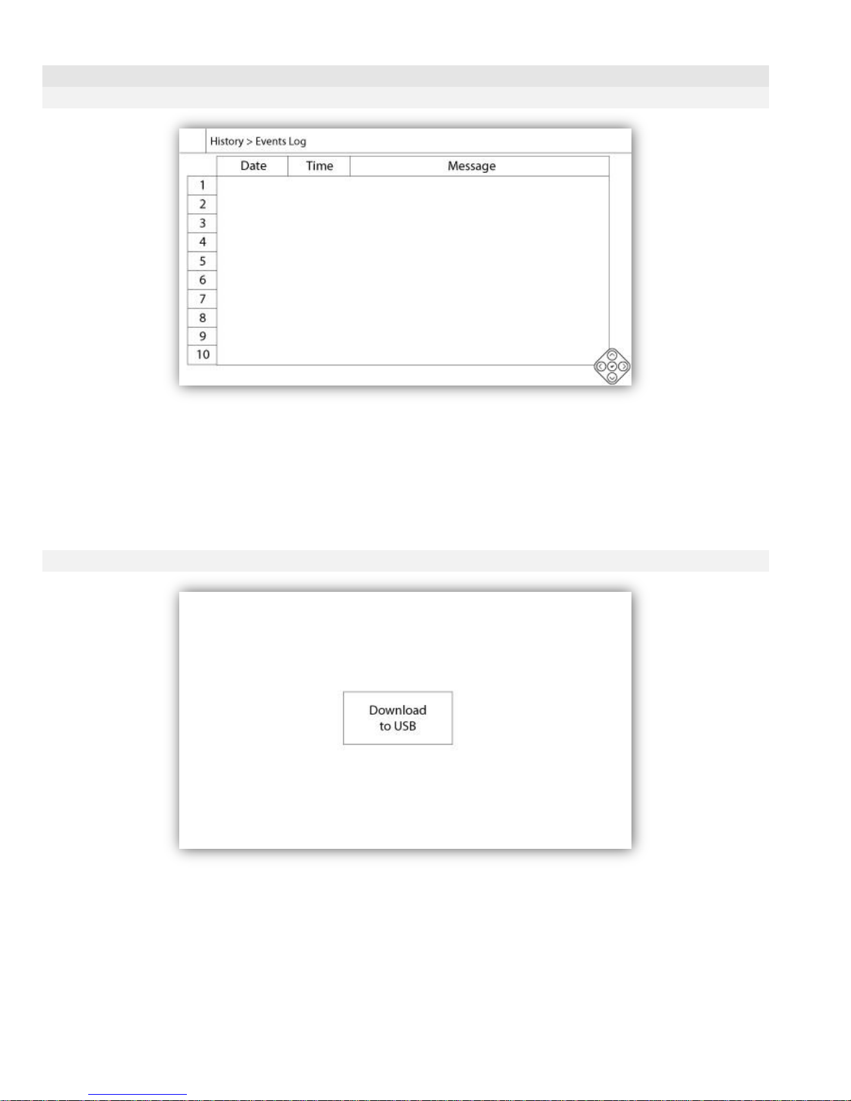
Details of the History Page
Events Page
History > Events Log
It shows the last 500 events which occurred in chronological order. The first column is the date, the second one is
the time of occurrence and the third column is the “Event message”. To obtain a log that is older than 500 events,
visit the “Download to USB Device” page and select “Events”. This method will generate a file containing all events
logs in the ViZiTouch history.
The contextual navigation pad is implemented in this page. It allows quick navigations functions, like “previous
page”, “next page”, “first page” and “last page”. As always, clicking on the Navigation Pad Icon in the lower right
corner of the screen will pop-up the Navigation Pad functions specific for this page.
Download to USB Device
History > Download to USB
39
Page 40
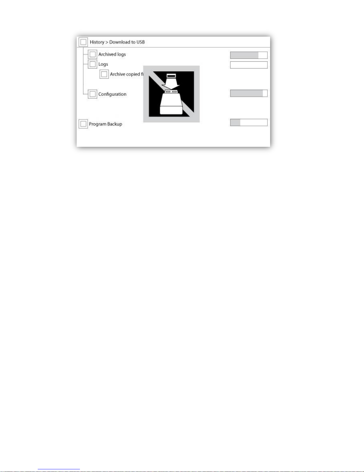
To download information from the ViZiTouch to a USB Device a user with at least a "level 1" password must be
logged in. The first square beside the title is a "Select All" button. Pressing it will select all categories except
"Archive copied files", which serves a separate purpose. The "Download to USB" button will execute the command.
The entire right side is filled with different progress bars, to help monitor the current transfer. If a USB Device is not
present or if there is an error, a message saying "Could not mount USB drive" will appear and any further action is
cancelled. To try again, remove the device, re-insert and press the button once more.
-Archived logs: All logs files that were archived using the "Archive copied files" square button. The purpose of
archiving files is to free up memory on the ViZiTouch by archiving older log files.
-Logs: All logs are currently available in the ViZiTouch memory. A "Comma Separated Values" or ".csv" file is
created every day and is named accordingly. Most software in modern computers will be able to read and interpret
these files. The log files contain the event logs, the pressure logs and the power logs.
-Configuration: All configuration parameters contained in a ".txt" file, including but not limited to nominal values,
serial number, calibration parameters.
Program Backup: A compressed and encrypted file, only readable by the ViZiTouch. This allows the user to copy a
complete ViZiTouch to another one. IMPORTANT: The ViZiTouch is not in service while downloading the program
backup.
40
Page 41
The Statistics
All Time Statistics
History > All Time Statistics
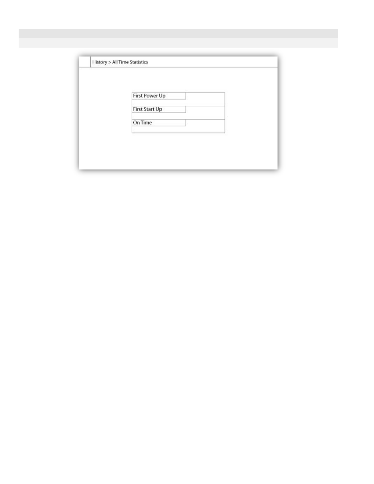
All statistics shown here are calculated since the controller's first start-up was done. All dates are in the
YYYY.MM.DD format and all time references are in the HH:MM:SS format.
-First Power Up: Date and time of when the controller was first powered up.
-First Start Up: Date and time of when the controller's first start-up was completed.
-On Time: Total duration of controller powered on since the first power-up. In Day.Hour.Minutes.
41
Page 42

How to Test:
Charger 1 Fail
Unpower the charger 1 by putting the circuit breaker in the off position.
Charger 2 Fail
Unpower the charger 2 by putting the circuit breaker in the off position.
DC Failure
Switch Circuit Breaker 3 (CB3) and Circuit Breaker 4 (CB4) in Off position or disconnect #6 and #8 engine wires
(See drawing for more details).
Controller Trouble
To activate this common alarm, at least one of the following alarms must be active: Charger Failure 1, Charger
Failure 2, DC Failure, Faulty Pressure Transducer or Weekly Test Check Solenoid Valve.
Low Fuel Level
Disconnect Fuel Level connector. Depending of your sensor type, put a jumper between positive pin (left) or negative
pin (right) and signal pin (middle) of this connector (See drawing for more details).
High Fuel Level
Disconnect Fuel Level connector. Depending of your sensor type, put a jumper between positive pin (left) or negative
pin (right) and signal pin (middle) of this connector (See drawing for more details).
Fuel Tank Leak
Put a jumper between Fuel Tank Leak input and ground (See drawing for more details).
AC Failure
Make sure both batteries are connected and all circuit breakers are in On position. Switch Circuit Breaker 1 (CB1)
and Circuit Breaker (CB2) in Off position. Disconnect J44 from the I/O board.
Water Reservoir Empty
Put a jumper between Water Reservoir Empty input and ground (See drawing for more details).
High Water Level
Disconnect Water Level connector. Depending of your sensor type, put a jumper between positive pin (left) or
negative pin (right) and signal pin (middle) of this connector (See drawing for more details).
Water Reservoir Low
Disconnect Water Level connector. Depending of your sensor type, put a jumper between positive pin (left) or
negative pin (right) and signal pin (middle) of this connector (See drawing for more details).
Pump Room Alarm
To activate this common alarm, at least one of the following alarms must be active: Low Fuel Level, High Fuel Level,
Fuel Tank Leak, AC Fail, Low Ambient Temperature, High Ambient Temperature, Low Suction Pressure, Water
Reservoir Empty, High Water Level or Water Reservoir Low.
Fail to Start
Disconnect #1, #9, #10 and #12 engine wires (See drawing for more details). Start the cranking sequence (Example:
Remove Remote Automatic Start jumper). Wait until the cranking sequence ends.
Technical Documents
42
Page 43

Overspeed
You need to be logged in to do this test. Press Config button (On the membrane). Go to Config>Advanced>Engine
Speed. Start your engine. Press Overspeed Test button.
Electronic Control Module Selector Switch in Alternate Position (301)
Disconnect #301 engine wire. Put a jumper between #301 input and ground (See drawing for more details).
Fuel Injection Malfunction (302)
Disconnect #302 engine wire. Put a jumper between #302 input and ground (See drawing for more details).
Electronic Control Module Warning ( 303 )
Disconnect #303 engine wire. Put a jumper between #303 input and ground (See drawing for more details).
Electronic Control Module Fault ( 304 )
Disconnect #304 engine wire. Put a jumper between #304 input and ground (See drawing for more details).
Low Engine Temperature (312)
Disconnect #312 engine wire. Put a jumper between #312 input and ground (See drawing for more details).
Low Oil Pressure
Disconnect Oil Pressure connector. Depending of your sensor type, put a jumper between positive pin (left) or
negative pin (right) and signal pin (middle) of this connector (See drawing for more details).
High Engine Temperature
Disconnect Engine Temperature connector. Depending of your sensor type, put a jumper between positive pin (left)
or negative pin (right) and signal pin (middle) of this connector (See drawing for more details).
Battery 1 Failure
Disconnect #6 engine wire (See drawing for more details).
Battery 2 Failure
Disconnect #8 engine wire (See drawing for more details).
Weak Battery 1
You need to be logged in to modify these settings. Press Config button (On the membrane). Go to
Config>Advanced>Factory Settings 2. Change Weak Battery 1 setpoint to maximum allowable.
Weak Battery 2
You need to be logged in to modify these settings. Press Config button (On the membrane). Go to
Config>Advanced>Factory Settings 2. Change Weak Battery 2 setpoint to maximum allowable.
Battery 1 Overvoltage
You need to be logged in to modify these settings. Press Config button (On the membrane). Go to
Config>Advanced>Factory Settings 2. Change Overvoltage Battery 1 setpoint to minimum allowable.
Battery 2 Overvoltage
You need to be logged in to modify these settings. Press Config button (On the membrane). Go to
Config>Advanced>Factory Settings 2. Change Overvoltage Battery 2 setpoint to minimum allowable.
Loss of Continuity 1
Disconnect #9 engine wire (See drawing for more details). Wait 1-2 minutes.
Loss of Continuity 2
Disconnect #10 engine wire (See drawing for more details). Wait 1-2 minutes
Low Pneumatic Pressure
Put a jumper between the Low Pneumatic Pressure input and ground (See drawing for more details). Take note that
this alarm will stop the pneumatic cranking sequence.
43
Page 44

Engine Trouble
To activate this common alarm, at least one of the following alarms must be active: Fail to start, Overspeed,
Electronic Control Module Selector Switch in Alternate Position (301), Fuel Injection Malfunction (302), Electronic
Control Module Warning (303), Electronic Control Module Fault (304), Low Engine Temperature (312), Low Oil
Pressure, High Engine Temperature, Battery 1 Failure, Battery 2 Failure, Loss of Continuity 1, Loss of Continuity 2,
Overpressure or Low Pneumatic Pressure
Low Spare Temperature
Disconnect the Spare Temperature connector. Depending of your sensor type, put a jumper between positive pin
(left) or negative pin (right) and signal pin (middle) of this connector (See drawing for more details).
Flow Start
Put a jumper between the Flow Start input and ground (See drawing for more details).
Cooling No Flow
Put a jumper between the Cooling No Flow input and ground (See drawing for more details).
Flow Meter On
Put a jumper between the Flow Meter On input and ground (See drawing for more details).
Engine Fail When Running
Start the engine. Depending of your engine type, disconnect #1 or put a jumper between #12 and #6 to stop the
engine. (See drawing for more details).
IO Diesel Communication Error
Press Reset button of the Diesel IO Board (Small button close to the phone jack)
IO Expansion 1 Communication Error
Press the Reset button of the Expansion 1 IO Board (Small button close to the phone jack)
IO Expansion 2 Communication Error
Press the Reset button of the Expansion 2 IO Board (Small button close to the phone jack)
IO Expansion 3 Communication Error
Press the Reset button of the Expansion 3 IO Board (Small button close to the phone jack)
IO Expansion 4 Communication Error
Press the Reset button of the Expansion 4 IO Board (Small button close to the phone jack)
Low Pump Room Temperature
Put a jumper between Low Pump Room Temperature input and ground (See drawing for more details).
Main Relief Valve Open
Put a jumper between Main Relief Valve Open input and ground (See drawing for more details).
Pneumatic Fail to Start
Disconnect the TB6 relay connector. Disconnect #1, #9, #10 and #12 engine wires (See drawing for more details).
Start cranking sequence (Example: Remove Remote Automatic Start jumper). Wait until the cranking sequence
ends.
Hydraulic Fail to Start
Disconnect the TB6 relay connector. Disconnect #1, #9, #10 and #12 engine wires (See drawing for more details).
Start cranking sequence (Example: Remove Remote Automatic Start jumper). Wait until the cranking sequence
ends.
44
Page 45
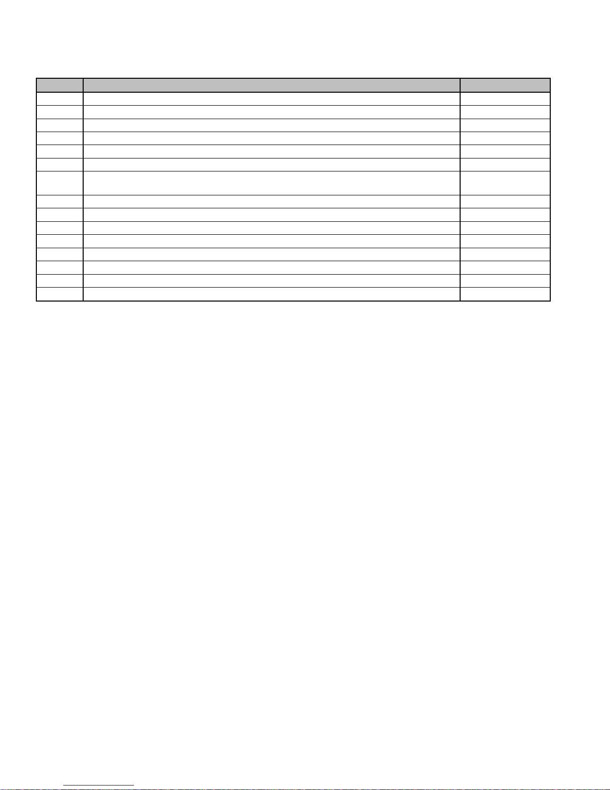
Patents
Country
Title
Grant No
CA
Mechanical activator for contactor
2741881
US
Mechanical activator for contactor
US8399788B2
CA
Mechanical activator for electrical contactor
165512
CA
Mechanical activator for electrical contactor
165514
US
Mechanical activator for electrical contactor
D803794
US
Mechanical activator for electrical contactor
Patent pending
EP
Mechanical activator for electrical contactor
002955393-
0001/2
AE
Mechanical activator for electrical contactor
Patent pending
AE
Mechanical activator for electrical contactor
Patent pending
CA
Fire pump digital operator
163254
US
Fire pump digital operator interface
D770313
AE
Fire pump digital operator interface
Patent pending
EP
Fire pump digital operator interface
002937250-0001
CA
System and method for detecting failure in a pressure sensor of a fire pump system
Patent pending
US
System and method for detecting failure of a pressure sensor in a fire pump system
Patent pending
45
Page 46
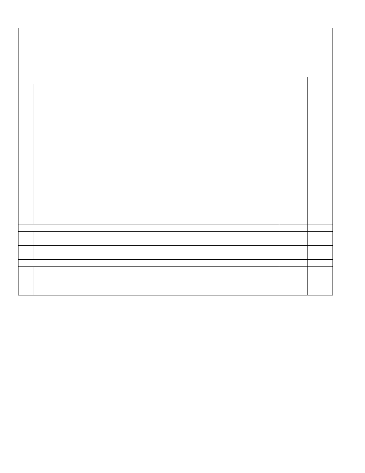
TORNATECH MODEL HFD DIESEL FIRE PUMP CONTROLLER
PRE- FIELD ACCEPTANCE TEST
CHECK LIST
Note: This document should be an official indication of whether or not the installation and general condition
of the equipment is adequate for a field acceptance test. This document should also aid the individual
responsible for executing the field acceptance test to decide whether or not to carry out the field acceptance
test of the equipment.
Installation Check List:
YES
NO
1
Verify that the nameplate voltages of the Fire Pump Controller corresponds with the AC
voltage available and the DC starting voltage of the engine.
2
Visual inspection for any damage to the exterior of the Fire Pump Controller. Make sure
the enclosure, alarm bell, selector switch, membrane and display are not damaged.
3 Verify that the Fire Pump Controller has been installed within sight of the pump and engine
or motor.
4 Verify that the Fire Pump Controller has been installed not less than 12 inches from the
floor of the mechanical room.
5
Verify that all electrical connections to the Fire Pump Controller are done using liquid tight
conduit and connectors.
6
With the Fire Pump Controller door open, visually inspect for any drill chips, dirt or foreign
objects in the bottom of the enclosure, loose wires, broken components and general
proper electrician workmanship.
7
Verify that the correct AC voltage is supplied to the controller by taking a voltage reading at
the L & N (220-240) terminals.
8 Verify that the terminal connections between the Fire Pump Controller and the engine (1 to
11 and 12 for Caterpillar engines) are properly done.
9 Verify that wiring to terminals #6, #8 (batteries) and #11 (ground) are of the appropriate
gauge size. See label inside controller.
10
Verify proper grounding of the Fire Pump Controller.
Initial Power-Up Check List:
YES
NO
1
With the Fire Pump Controller door open, turn to “ON” the circuit breakers CB3 and CB4
(DC) then CB1 and CB2 (AC), then IS1. This sequence is very important.
2
Close the Fire Pump Controller door. Verify on the ViZiTouch Homepage that the correct
battery voltage appears.
Manual and Automatic Start Check List:
YES
NO
1
Verify starting of engine by pressing the “Start” membrane button.
2 Stop engine by pressing the “Stop” membrane button.
3 Verify the starting of engine by pressing the emergency push button.
4 Stop engine by pressing the “Stop” membrane button.
46
Page 47

Tornatech Controller S/N: _________________________________________
Installation address: _________________________________________
_________________________________________
_________________________________________
Check list completed? _____________Yes _____________ No
Check list completed by: __________________________________________
Company: __________________________________________
Date: __________________________________________
Witnessed By: __________________________________________
Comments: ___________________________________________________________________________
___________________________________________________________________________
___________________________________________________________________________
___________________________________________________________________________
___________________________________________________________________________
___________________________________________________________________________
47
Page 48

48
 Loading...