

Tornado Floorkeeper 99328, Floorkeeper 99332, Floorkeeper 99429, Floorkeeper 99329, Floorkeeper 99333 Operation And Maintenance Manual
Page 1

Tornado
https://harrissupplyind.com - To Order Parts Call 608-268-8080
Operation and Maintenance Manual
For Commercial Use Only
TORNADO® INDUSTRIES
7401 W. LAWRENCE AVENUE
CHICAGO, IL 60706
(708) 867-5100 FAX (708) 867-6968
www.tornadovac.com
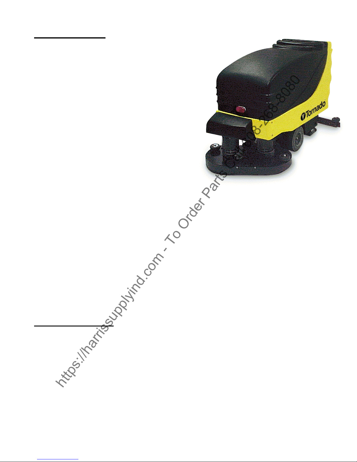
Long-Range Floorkeeper Automatic Scrubber
Form No. L9332ED Revised 11/05 2006 Tornado Industries All rights reserved.
Catalog No.
99328 & 99332
For Parts List see L9332EDP
Effective 11/7/2005
Page 2

NOTES
https://harrissupplyind.com - To Order Parts Call 608-268-8080
2
Page 3

This illustrated instruction book covers:
https://harrissupplyind.com - To Order Parts Call 608-268-8080
MODEL 99328 99332
SIZE 28" 32”
VOLTS (CHARGER) 36V 36V
AMPS 20 20
CAPACITY 20 GAL. (79l) 20 GAL (79l)
SERIES D D
All specifications are subject to change without notice.
TABLE OF CONTENTS
WARRANTY 4
INTRODUCTION 5
UNIT CONTROLS AND INDICATORS 6
INSTALLATION
BATTERY 8
SQUEEGEE 9
RECOVERY TANK DRAIN 11
BRUSHES 11
PRE START-UP
FILLING SOLUTION TANK 12
PREVENTATIVE MAINTENANCE PROGRAM
INTRODUCTION 13
BATTERY CARE 13
BATTERY CHARGING 15
SQUEEGEE BLADES 16
SQUEEGEE ADJUSTMENT 17
VACUUM AND WATER RECOVERY SYSTEM 18
SOLUTION AND RECOVERY (Vacuum) TANKS 18
VACUUM MOTOR 19
WHEELS 19
LUBRICATING YOUR MACHINE 20
MOTOR BRUSH REPLACEMENT INTERVALS 20
TROUBLESHOOTING INSTRUCTIONS
VACUUM SYSTEM (POOR SUCTION) 21
POOR SOLUTION FLOW 22
ELECTRICAL PROBLEMS 23
BATTERIES NOT HOLDING CHARGE 23
TROUBLESHOOTING PERFORMANCE SYMPTOMS CHART 24
LCD DISPLAY DIAGNOSTIC ERROR CODES 25
PREVENTATIVE MAINTENANCE CHECKLIST 28
3
Page 4

Thank you for choosing Tornado products. We are proud to offer the most
https://harrissupplyind.com - To Order Parts Call 608-268-8080
complete line of commercial and industrial cleaning equipment in the industry.
Our reputation for quality, innovation and durability is unsurpassed.
* Effective January 1st, 2005. Terms subject to change without notice.
1) Windshear™ Blower-Dryer, Insulation Blowers, T191, T201, T12/1, CV 30, CV 38, CW 50, CW
100, Pro PAC Vacs, Duo-Upright Carpetkeepers™, Gas & Electric Pressure Washers, and all
chargers are warranted for 1 (one) year for both parts and labor.
2) Warranties on all riding sweepers including the ICC1, KM 100/100 R, KMR 1250, and KMR
1700 are 24 months parts/6 months labor OR 1000 hours of operation, whichever comes
first. Warranties on the 75/140 & 90/140 are 24 months parts/12 months’ labor OR 1,000
hours of operation whichever comes first.
3) All non-wear item parts purchased after warranty expiration are warranted for 90 days.
4) Warranty starts from the date of sale to the consumer or, at Tornado’s discretion, 6 months
after dealer purchased the unit from Tornado, whichever comes first.
Note: Tornado, The Latest Dirt, Floorkeeper, Carpetkeeper, Carpetrinser, Carpetrinser/Dryer,
Headmaster, Taskforce, PAC-VAC, T-Lite, Glazer, Windshear, Max-Vac, CV 30, CV 38, and
Trot-Mop are trademarks of Tornado Industries.
1-800-VACUUMS
Chicago area: (708) 867-5100
Fax: (708) 867-6968
7401 W. Lawrence Avenue
Chicago, IL 60706
4
Page 5
INTRODUCTION
https://harrissupplyind.com - To Order Parts Call 608-268-8080
Congratulations on the purchase of your new
Tornado Long-Range Floorkeeper! The LongRange Floorkeepercombines many advanced
features to maximize reliability, performance,
and ease of use. The most notable addition is
the incorporation of the industry’s first fully
functional digital control and display system on
an automatic floor scrubber. With it, you’ll be
able to easily and accurately monitor an
assortment of system settings and conditions.
Tornado’s new digital controller has a unique
soft-start feature that increases both efficiency
and powertrain lifespan.
The Long-Range Floorkeeper’s simplified
wiring harness uses quick-disconnects, and
combined with the digital controller, it makes
servicing and troubleshooting easy. A tough
rotomolded housing extends over an advanced
one-piece steel weldment, making this new
Long-Range Floorkeeper both more rugged
and much lighter than previous Long-Range
models.
Additional features include removable 20-gallon solution and vacuum tanks, a reliable 18:1 gear
ratio transaxle, non-marking 11” tires, easy-access batteries, and error code generation on its
LCD display. The new Long-Range Floorkeeper Automatic Scrubber was designed and built
to exceed your needs for durability and serviceability in demanding commercial environments.
This manual is designed to instruct your personnel in the operation, maintenance and methods
of troubleshooting on your Tornado Long-Range Floorkeeper. Please read through this
manual and keep it handy to ensure that you get maximum satisfaction and value from this new
advance in floor care.
OBSERVE THESE PRECAUTIONS
FOR SAFE USE OF THIS MACHINE
TO AVOID DANGER:
• Back the machine down inclines or ramps. Do not store machine on inclines.
• Make certain that the power switch is OFF before removing or installing brushes.
• Use care when working on electrical terminals —short circuits can cause burns and throw sparks.
• Disconnect both positive and negative battery terminals before attempting any adjustment or main-
tenance. Brush or traction drive motors and drive components could cause injury if started while
being worked on.
• Charge batteries in a ventilated room where gases cannot accumulate. Gases given off during
charging could ignite in a confined space. Make certain that the top covers are open when
charging so gases cannot accumulate.
• Battery acid can cause injury to the eyes or burn the skin.
5
Page 6

Unit Controls and Indicators
https://harrissupplyind.com - To Order Parts Call 608-268-8080
Control Panel
1. Vacuum Motor Switch
2. Variable Speed
Control Knob
3. LCD Display
4. Display Mode
Button
5. Brush Position
Switch
Rear Controls
6. Adjustable
Solution
Control
7. Dual Drive
Levers
8. Dual Reverse
Buttons
9. Emergency
Stop Switch
10. Key Lock
11. Circuit Breaker
12. Squeegee Control Lever
13. Recovery Tank Drain Hose
6
Page 7

Unit Controls and Indicators
https://harrissupplyind.com - To Order Parts Call 608-268-8080
Display Screens
Use the Display Mode Button (to the right of the display) to toggle between three unique
screens. Each screen displays a different set of icons and numerical readouts to give you useful
information about your Long-Range Floorkeeper’s operating status. For particulars on
diagnostic fault code information, see page 24.
7
Page 8

INSTALLATION
https://harrissupplyind.com - To Order Parts Call 608-268-8080
Batteries
Raise top cover using handle, and pivot forward until
retainer cords are taut.
CAUTION
Batteries are heavy. To avoid injury, use two people
to lift into position.
Place batteries in metal tray liner. Orient each battery
exactly as shown in bottom photo, or refer to chart
located under the hood. Ensure that positive and
negative terminals are positioned and connected
correctly.
CAUTION
Observe polarity.
Place battery terminal protectors over posts.
WARNING
Battery acid can cause severe burns. Make sure
battery caps are tight to avoid spills or splashing of
acid.
Close cover.
8
Page 9

INSTALLATION
https://harrissupplyind.com - To Order Parts Call 608-268-8080
Squeegee
Make sure squeegee adjustment lever is locked in UP
position. Squeegee can be locked in UP position by
raising lever and moving it to the left.
Loosen the two starwheel knobs on the
squeegee assembly. Make sure the black
metal bracket on the squeegee assembly is
aimed forward, toward the concave side of the
squeegee. Lift the squeegee bracket and
washers (if present), and slide the squeegee
assembly onto the rocker plate.
The bracket and washers should rest on top of
the rocker plate, as shown.
9
Page 10

INSTALLATION
https://harrissupplyind.com - To Order Parts Call 608-268-8080
Squeegee
Push the squeegee as far forward as it can go.
Tighten the starwheels to secure the
squeegee in place.
Insert the hose end over the squeegee
assembly nozzle throat. Press down tightly.
Refer to the Maintenance section to properly
adjust the squeegee position for best wiping
performance.
• Never store machine with squeegee in down
position. This can damage the flexible
blades.
• Always raise squeegee while backing up, to
prevent potential damage to the squeegee
and its mounting mechanism.
10
Page 11

INSTALLATION
https://harrissupplyind.com - To Order Parts Call 608-268-8080
Recovery Tank Drain
Install the drain door on its mounting hardware. Make sure the
starwheels are tight. Hang the top of the hose on the hose
bracket.
Brushes
1. Raise the brush heads using the switch on
the control panel.
2. Place the brushes or pad holders under
the brush cover. Center the brushes on the
brush couplers. Pull up to lock in place.
3. Check to see that the two solution feed
hoses are connected to their fittings on top
of the brush cover.
Page 12

PRE START-UP
https://harrissupplyind.com - To Order Parts Call 608-268-8080
Turn key and power switch on and lower brushes to
test. Brush motors will automatically turn on when
brushes are lowered.
Filling Solution Tank
1. Raise top cover.
2. Always empty recovery tank before filling solution
tank. This will eliminate overfilling of recovery
tank.
Lift solution tank cover and fill.
3. Close top covers by pushing covers down.
You are now ready to operate your machine.
Follow maintenance schedule on page 28 to ensure proper operation of your machine.
12
Page 13

TORNADO FLOORKEEPER
https://harrissupplyind.com - To Order Parts Call 608-268-8080
PREVENTIVE MAINTENANCE PROGRAM
Introduction
This section is designed to instruct your personnel in methods of maintenance on the Tornado
Long-Range Floorkeeper. By following these procedures, repair costs and down time will be
greatly reduced. These procedures are for simple repairs that can easily be done by your own
personnel.
WARNING
Battery acid is toxic and corrosive; avoid bodily
contact.
First Aid:
EYES: Wash with liberal quantities of running
water for 15 minutes.
SKIN: Flush area with plentiful amounts of
running water.
INGESTION: Give milk to drink, DO NOT induce
vomiting, call a physician.
SPILLS: Wash with water or neutralize with
sodium carbonate or bicarbonate
(baking soda).
Battery Care
Batteries must be checked daily. The water level
must be maintained at least 1/4” above top of cell
plates in each battery.
1. Raise top covers and lock in place.
2. Remove battery caps and fill.
NOTE: Fill batteries with distilled water only. This
will increase battery life substantially.
13
Page 14

MAINTENANCE
https://harrissupplyind.com - To Order Parts Call 608-268-8080
CAUTION
Do not overfill the battery cells. Do not use a hose
or pail. If batteries are accidentally overfilled,
remove excess water with a hydrometer or similar
device. Dispose of excess in accordance with
local, state and federal regulations.
3. After filling batteries, replace the battery
caps. Using baking soda or ammonia and
water solution, saturate a cloth and wring until
drip dry. Use this cloth to wipe the battery tops.
1. The battery terminals and connections need to
be coated with a protective lubricant to prevent
corrosion.
WARNING
Avoid accidental contact with battery terminals and
possible electrical shock. Replace protective
plastic terminal covers after battery maintenance.
14
Page 15

MAINTENANCE
https://harrissupplyind.com - To Order Parts Call 608-268-8080
The battery charger requires minimal maintenance.
It should be kept clean and all connections are to
be tightly secured. In the event of intermittent
operation, examine and tighten, if necessary, all
connections. BE SURE THE CHASSIS IS
SECURELY GROUNDED. If problems cannot be
resolved consult a qualified service center.
OPERATING INSTRUCTIONS
1. Open the machine cover. Keep the cover open
during the charging process.
2. Disconnect the Andersen connector on the
machine.
3. Connect the battery charger to the battery side
of the Andersen connector on the machine.
This is done by grasping the plug body and
pushing it straight back into the receptacle until
it is fully engaged. The black wire must be
connected to battery negative (-), and the red
or white wire to battery positive (+). Make sure
all connections are clean and tight.
4. Connect AC supply cord to a properly
grounded 120 volt, 60 hertz, single-phase
outlet.
5. The ammeter will start after a short delay as
indicated by the transformer hum and the
ammeter movement.
WARNING: LEAD ACID BATTERIES GENERATE GASSES WHICH
CAN BE EXPLOSIVE. CHARGE ONLY IN WELL-VENTILATED
AREAS. DO NOT DISCONNECT CHARGER DC OUTPUT
TERMINALS FROM BATTERY WHEN CHARGER IS ON. THE
RESULTING ARCING AND BURNING COULD CAUSE THE
BATTERY TO EXPLODE. KEEP SPARKS, FLAME, AND SMOKING
MATERIALS AWAY FROM BATTERY.
If the charger must be stopped, always disconnect the AC supply cord from its outlet before disconnecting the DC
output terminals from the battery.
6. Monitor the ammeter for correct charge current. The initial charge current should be approximately 20 amps. If
the batteries have not been discharged, or the AC supply voltage is lower than 120 volts, the initial charge rate
may be less. If the batteries have been excessively discharged, or AC supply voltage is higher than 120 volts,
the initial charge rate may be more than 20 amps.
7. Charge current will gradually taper to approximately 6 amps depending on the age and condition of the
batteries. Charger turns off automatically when battery is fully charged. Charge time varies with battery size
and depth of discharge. Allow 10-11 hours for normal charging. Severely discharged batteries may require
more time to be properly charged and equalized.
8. After the charger has been turned off, disconnect the DC outlet plug from the battery and the AC supply cord
from the outlet.
15
Page 16

MAINTENANCE
https://harrissupplyind.com - To Order Parts Call 608-268-8080
Squeegee Blades
Whenever the squeegee leaves streaks or
water trails, debris at the blade edges is the
primary cause. Clean the blade edges with a
damp cloth.
If a squeegee blade is worn or nicked, raise
the squeegee assembly and remove the
entire assembly: disconnect the vacuum
hose, loosen both star handles, and slide the
squeegee assembly out.
Remove both guide wheels and end caps.
Pull each blade out from one end, and slide
its replacement into place.
Replace the end caps and guide wheels.
Slide the squeegee assembly back onto its
mount, and tighten both star handles.
16
Page 17

MAINTENANCE
https://harrissupplyind.com - To Order Parts Call 608-268-8080
Squeegee Adjustment
Before resuming operation, check the
squeegee blades for proper engagement to
the floor.
First, lower the squeegee and push or drive
the machine forward several inches, then
look at the consistency of the rear blade flex
all along its length as it rests on the floor. If
the rear blade does not appear evenly
loaded, readjust the squeegee assembly
using the directions below.
Loosen the two rocker thumbscrews. Hold
the squeegee and rotate it forward or
rearward until the squeegee blades contact
the floor evenly. Tighten the rocker
thumbscrews.
Push the machine forward slightly and
recheck for even blade contact.
Replacement Blade Part Numbers:
Standard K62732150
Oil Resistant K62732090
Non-Marking Oil-Resistant K62732060
17
Page 18

MAINTENANCE
https://harrissupplyind.com - To Order Parts Call 608-268-8080
Vacuum and Water Recovery System
NOTE: A dirty or clogged filter will greatly reduce
suction and the ability of the machine to recover
water.
Inspect the vacuum filter after each use as follows:
1. Disconnect hose.
2. Turn the two cam-shaped thumb locks.
3. Remove filter assembly.
4. Rinse the filter screen with clean water.
5. Drain and flush tank with clean water.
6. Leave filter assembly out of tank to allow system to dry when
not in use.
A liquid shutoff is built into the filter system to prevent overfilling
tank. Do not disassemble or modify the white plastic float, or
vacuum motor damage may result.
Solution and Recovery (Vacuum) Tanks
Draining Recovery (Vacuum) Tank:
1. Lift drain hose and remove from hook.
2. Insert end of hose into large pail or drain area.
3. Push ball to the side and drain. (Do not remove ball from
hose.)
4. For more extensive cleaning of tank, loosen two thumb nuts
and remove cover. Flush out tank with clean water as
necessary.
18
Page 19

MAINTENANCE
https://harrissupplyind.com - To Order Parts Call 608-268-8080
Draining Solution Tank:
1. Locate drain hose at front of unit and position over
acceptable floor drain or container.
2.Turn valve handle to open drain valve.
3.Return valve handle to closed position. Tuck drain
hose back on machine.
Flush and clean tanks after each use and allow to air
dry to eliminate odors and corrosion of vacuum motor.
Vacuum Motor
To service vacuum motor which is located above recovery tank:
1. Disconnect vacuum hose clamp.
2. Remove four screws.
3. Disconnect wires and remove cover.
4. Remove vacuum motor to service.
Wheels
Machines are equipped with either pneumatic or
optional foam-filled tires. Be sure to keep pneumatic
tires at 48-50 psi to ensure proper machine
performance. No service is required for foam-filled
tires.
19
Page 20
MAINTENANCE
https://harrissupplyind.com - To Order Parts Call 608-268-8080
Lubricating Your Machine
WARNING
Unit must be switched “OFF” before greasing wheel
fittings. Wipe off excess.
Once a week grease swivel casters with a grease
gun. Each caster has two fittings: one at the axle
(A) and one on the swivel part of caster (B).
Motor Brush Replacement
Use the appropriate hour meter on the LCD Display to monitor runtimes for each motor.
Tornado recommends changing motor brushes at the intervals specified below in order to avoid
potential damage to the commutators. Replacement brushes need to be inspected and
changed more often due to commutator wear. Always permanently record any brush
inspections and replacements you make.
Don’t attempt to use the Motor Fault Error feature of the LCD Display as a signal that motor
brushes need changing. A Motor Fault that occurs directly from brush wear would indicate a
high risk of motor damage.
Motor Recommended Motor Brush Change Interval
Transaxle 1800 hours initially, 900-1400 hours for replacements
Brush 2600 hours initially, 1300-2000 hours for replacements
Vacuum 600-650 hours initially, 400-500 hours for replacements
20
Page 21

TORNADO LONG-RANGE FLOORKEEPER®
https://harrissupplyind.com - To Order Parts Call 608-268-8080
TROUBLESHOOTING INSTRUCTIONS
This section is designed to instruct your personnel in methods of troubleshooting on the
Tornado Long-Range Floorkeeper.
Vacuum System (Poor Suction)
During machine operation, if the vacuum motor is running but the solution is not being picked
up, do the following:
Check for:
1. Full recovery tank. When tank is full, liquid shutoff closes to prevent water from entering
vacuum motor.
2. Loose hose on float/filter, creating an air leak.
3. Clogged filter.
4. Clogged stand pipe near filter. Remove cap to inspect and clean with hose.
5. A. Check to see that ball closure is in place on end of drain hose.
B. Check to see that thumb nuts on recovery tank drain cover are tight.
C. Check to see if liquid shutoff unit is properly seated on top of recovery tank, the filter
gasket is not damaged, and cam lock nuts are tight.
21
Page 22

TROUBLESHOOTING
https://harrissupplyind.com - To Order Parts Call 608-268-8080
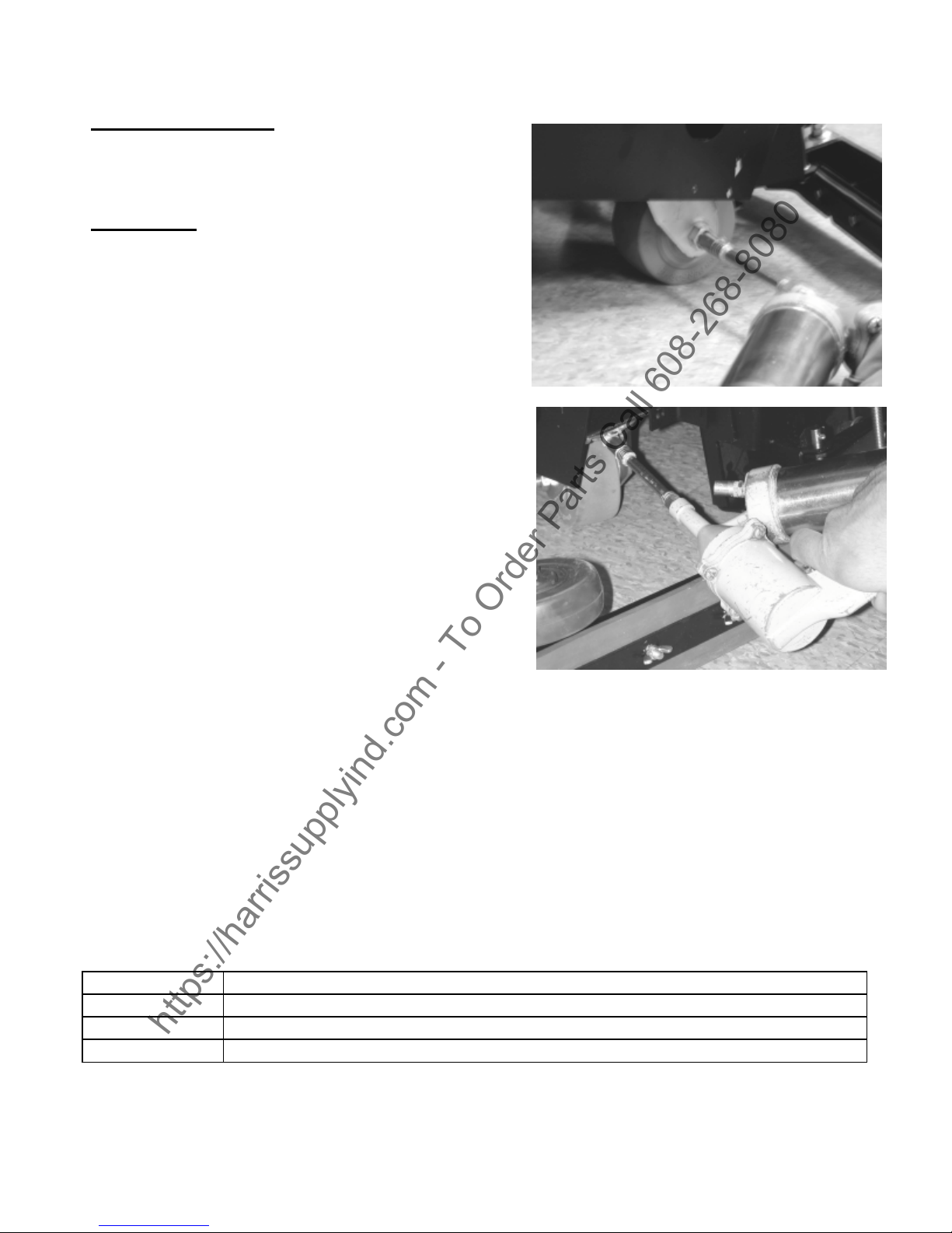
6. Remove vacuum hose from squeegee by pulling
hose off squeegee throat.
7. With the vacuum motor on, place your hand over
the vacuum hose intake. If suction is strong, a
blockage is in the squeegee throat.
Clear this blockage by pushing a screwdriver, or
any similar tool, downward through the top of
the squeegee throat.
NOTE: Performing these maintenance
procedures will avoid problems with the
recovery system requiring outside repair
service. Always be very sure the vacuum
system is clear of any blockage before calling
for service.
Poor Solution Flow
If an inadequate supply of solution is reaching the floor, check the solution hoses for kinks.
These hoses are connected to the brush drive assembly. If there are no kinks in the solution
hoses, pull the hoses from the brush cover fitting and check the entire line for blockage.
22
Page 23

TROUBLESHOOTING
https://harrissupplyind.com - To Order Parts Call 608-268-8080
Electrical Problems
If brush motors do not run, check the following:
1. Emergency Stop is pulled out.
2. Key Switch is in ON position.
4. Brushes are in down position.
9. Check the circuit breaker button in the back lower panel of the machine.
6. Replace control board.
Batteries Not Holding Charge
Check that the batteries have been given enough charge time to reach their full charge. This
will vary according to condition of the batteries.
Check the lights on the battery charger after charger shuts off:
A. Green light — Batteries are fully charged and are in good condition.
B. Amber light — All cells are OK but the total battery capacity is reduced. This usually
indicates that the batteries are aging.
C. Red light — The battery capacity is low and the entire charger-battery system needs to be
inspected by a qualified serviceman.
The automatic charger is designed to keep batteries at optimum operating charge levels.
NOTE: If red light comes on, inspect battery connections and water level.
23
Page 24

TROUBLESHOOTING
https://harrissupplyind.com - To Order Parts Call 608-268-8080
Check each cell with a hydrometer before and after charging to determine it batteries are weak.
Do not charge or use batteries when the liquid in any one or more cells measures less than
1.150 specific gravity. A fully charged battery should read 1.270 or better after cooling 1/2 hour.
Batteries that have been properly charged and still do not reach a full charge should be
discarded. One defective battery can weaken the other batteries. Replace the defective battery
if the battery pack is less than two years old. If over two years, replace the entire battery pack.
Daily Battery Maintenance Precautions
1. Add distilled water only.
2. Never add acid.
3. Keep vent caps tight when operating.
4. Keep battery tops clean and dry.
5. Keep water level 1/4” above cell plates.
6. Keep metal and excessive heat away from batteries.
7. Use TORNADO charger with correct voltage and current rating.
TROUBLESHOOTING PERFORMANCE SYMPTOMS
Poor Solution Pickup —
Vac motor not running;
Vac filter is clogged;
Recovery tank is full;
Squeegee or vac hose clogged, broken, disconnected;
Poor or no seal at filter, at squeegee or at vac motor;
Worn or misaligned squeegee blades;
Incorrect squeegee pressure;
Swing mechanism not functioning properly.
Squeegee Leaving Streaks —
Floors not properly swept; debris on blades;
Blades torn or otherwise damaged;
Solution Feed/Shutoff Problems — Clogging of screen, hose or valve; control rod disconnected.
Inadequate Scrub, Strip or Buff —
Brush motor not working - overload tripped;
Excessive brush or pad wear;
Going over very dirty spots too last;
Inadequate solution feed.
Losing Running Time —
Batteries or charger need servicing;
High current draw for high brush pressure.
24
Page 25

TROUBLESHOOTING
https://harrissupplyind.com - To Order Parts Call 608-268-8080
Diagnostic Electronic Fault Codes
Error codes displayed in the LCD Display indicate that the Electronic Control System may be
detecting problems with electrical connections, worn parts, power system controls, or batteries.
Be sure to write down the error code before calling your Authorized Tornado Distributor, Service
Center, or the Tornado Technical Service Department.
Error Codes Available in the LCD Display
Code Probable Cause Service Action
0003
0100
0204
0705
circuit between Tiller Hi and Lo
0706
Memory corrupt Replace Controller if not cleared by disconnecting batteries for 1 min
All 070x codes -Wiring short
Ref
Check for wiring short circuits on the 20 way connector on the Trio, the
16 way connector on the LCD (if used) and the wiring to the front panel
switches & controls and those switches & controls themselves.
0810
0811
0812
0813
0814
0815
0816
0817
0818
0A01
0B0B
1310
1500
1501
1507
1600
1704
1705
1706
1800
1802
1B20
1B21
1D02
1E03
All 081x codes – Throttle wiring
short or open circuits. 0816
and 0817 can be caused by
incorrect programming of the
ISO test parameter
Possible Controller fault Replace Controller if not cleared by disconnecting batteries for 1 min
Possible Controller fault Replace Controller if not cleared by disconnecting batteries for 1 min
Possible Controller fault Replace Controller if not cleared by disconnecting batteries for 1 min
All 150x codes - Check brake
& wiring for open or short
circuit
Voltage exceeds maximum Can be caused by poor or corroded connections to the batteries or a
Possible Controller fault Replace Controller if not cleared by disconnecting batteries for 1 min
Tiller settings updated in
programming
Inhibit inputs - Exact usage
dependent on programming
Check for wiring short circuits or broken wires on the 20 way connector
on the Trio, the 5 way connector on the LCD (if used) and the wiring to
the front panel speed / throttle control and the speed / throttle control
itself.
Check the Traction motor connection on the Trio and check the wiring
from this connector down to the Traction motor and checking
connections all the way. Otherwise possible fault in electro brake on
traction motor or possible Controller fault.
battery charger being connected.
Cycle the power via the keyswitch
Remove or correct what is causing the inhibit. Otherwise check for
wiring short circuits or broken wires on the 20 way connector on the
Trio and the wiring elsewhere on the machine. Otherwise incorrect
programming or operation of machine.
25
Page 26

1E04
https://harrissupplyind.com - To Order Parts Call 608-268-8080
2102
2103
2C00
2C01
2C02
2D01
2F01
3100
3101
3102
3103
3104
3105
3201
3210
3211
3212
3213
3214
3601
3602
3603
3608
3609
360A
360B
360C
360D
360E
7000
7001
Possible Controller fault Replace Controller if not cleared by disconnecting batteries for 1 min
Low voltage warning Recharge batteries immediately
Dependent on programming Recharge batteries immediately
Possible Controller fault Replace Controller if not cleared by disconnecting batteries for 1 min
Throttle in drive position during
switch on
All 310x codes - Probable short
circuit of output device or
wiring - can sometimes cause
permanent Controller fault.
Possible Controller fault Replace Controller if not cleared by disconnecting batteries for 1 min
Possible Controller fault Replace Controller if not cleared by disconnecting batteries for 1 min
All 70xx codes – Check wiring
of brake and freewheel switch
Incorrect operation of machine. Otherwise check the mechanical
condition of the throttle mechanism. Otherwise check for wiring short
circuits on the 20 way connector on the Trio, the 16 way connector on
the LCD (if used) and the wiring to the front panel switches & controls
and those switches & controls themselves.
Check the Traction, Brush and Vac motor connections on the Trio and
check the wiring from these connectors down to the Traction, Brush and
Vac motors checking connections all the way and also checking for
short circuits. Check for wiring short circuits or broken wires on the 14
way connector on the Trio and the wiring elsewhere on the machine.
Otherwise replace Controller.
Check for wiring short circuits on the 20 way connector on the Trio, the
16 way connector on the LCD (if used) and the wiring to the ffreewheel
switch and the switch itself.. Check the Traction motor connection on
the Trio and check the wiring from this connector down to the
electromagnetic brake on the Traction motor and check connections all
the way. Can be caused by excessive pushing or rolling down a slope
or incorrect operation of the machine.
Wiring fault on 6-way serial link
7500
between Trio and LCD
7501
7600
7601
LCD memory corrupt Disconnect batteries and wait for 1 min before re-applying power
Open circuit on brush motors
or brush motor wiring
Brush current overload
(“thermal” trip)
Check the wiring and connectors on the 6 way connections on the Trio
and LCD
Check the Brush motor connection on the Trio and check the wiring
from this connector down to the Brush motor and checking connections
all the way. Otherwise possible Brush motor fault.
Incorrect programming, incorrectly specified Brush motor, Brush motor
developing a fault, excessive resistance on brushes or brushes pushing
down too hard on floor.
26
Page 27

7602
https://harrissupplyind.com - To Order Parts Call 608-268-8080
7603
7604
7700
7701
7702
7703
7800
7801
7802
7900
7901
9000
Brush current overload
(“magnetic” trip)
Possible short circuit on brush
motors or wiring
Dependent on programming Incorrect software program - check program, otherwise possible
Open circuit on vac motors or
vac motor wiring
Vacuum current overload
(“thermal” trip)
Vacuum current overload
(“magnetic” trip)
Possible short circuit on
vacuum motors or wiring
Open circuit on traction motor
or traction motor wiring
Possible short circuit on
Traction motor or wiring
Traction motor current has
exceeded current limit for the
foldback time
E-stop input active or wiring
fault
E-stop input active or wiring
fault (programmed as belly
button)
Dependent on programming Brushes not fitted or incorrectly adjusted brush deck actuator
Incorrectly specified Brush motor, Brush motor developing a fault
Check the Brush motor connection on the Trio and check the wiring
from this connector down to the Brush motor and checking connections
all the way. Otherwise possible Brush motor fault.
controller fault.
Check the Vac motor connection on the Trio and check the wiring from
this connector down to the Vac motor and checking connections all the
way. Otherwise possible Vac motor fault.
Incorrect programming, incorrectly specified Vac motor, Vac motor
developing a fault, debris in Vac motor or airways blocked by debris
Incorrectly specified Vac motor, Vac motor developing a fault
Check the Vac motor connection on the Trio and check the wiring from
this connector down to the Vac motor and checking connections all the
way. Otherwise possible Vac motor fault.
Check the Traction motor connection on the Trio and check the wiring
from this connector down to the Traction motor and checking
connections all the way. Otherwise possible Traction motor fault.
Check the Traction motor connection on the Trio and check the wiring
from this connector down to the Traction motor and checking
connections all the way. Otherwise possible Traction motor fault.
Excessive driving up an incline, or machine driven up against an
obstacle or step.
Check for wiring short circuits on the 20 way connector on the Trio, the
16 way connector on the LCD (if used) and the wiring to the emergency
stop switch and the emergency stop switch itself. Otherwise incorrect
operation of machine.
Check for wiring short circuits on the 20 way connector on the Trio, the
16 way connector on the LCD (if used) and the wiring to the belly button
stop switch and the belly button switch itself. Otherwise incorrect
operation of machine.
Any other error code is an internal error and cannot be rectified externally. Contact your
Authorized Tornado Distributor, Service Center, or the Tornado Technical Service Department.
27
Page 28

MODEL 99328 and 99332
https://harrissupplyind.com - To Order Parts Call 608-268-8080
PREVENTIVE MAINTENANCE CHECKLIST
START OF OPERATION
DAILY MAINTENANCE
1. Unplug charger from Floorkeeper circuitry.
2. Close the solution tank dispenser drain and attach the drain plate to the recovery tank.
3. Assemble and install the vac filter and float cage on the recovery tank.
4. Give the machine a general visual inspection.
END OF OPERATION
1. Clean and wipe squeegee blades.
2. Remove float/filter from the vac tank, take the filter off of the float cage, clean and leave to air dry.
3. Drain both tanks, remove the recovery drain plate and open the solution tank drain valve. Flush both tanks and
leave them open to air dry.
4. Add distilled water to battery cells if required.
5. Charge the batteries.
WEEKLY MAINTENANCE
1. Clean and lubricate the caster wheels - use grease gun supplied with Floorkeeper.
2. Check the specific gravity of fully-charged battery cells: allow a 30 minute cool-down after charging (specific
gravity should be 1.270 to 1.280).
MONTHLY MAINTENANCE
1. Lubricate lift mechanisms (both brush and squeegee) with a light oil.
2. Adjust the brush pressure (mercury switch) if needed.
3. Check for wear or damage of brushes, pads and squeegee blades, replace if necessary.
4. Clean all battery terminals with baking soda and water.
5. Check batteries for damage, acid spills, cracks.
6. Lubricate handles and check for looseness.
7. Check the drain gaskets for wear and damage, replace if necessary.
8. Make sure all electrical connections are tight.
SEMI-ANNUAL MAINTENANCE
1. Check all motors, especially check for carbon brush wear, replace if necessary.
2. Grease all bearings.
ANNUAL MAINTENANCE
1. Tighten all loose linkages, screws and nuts on entire machine.
28
 Loading...