

Page 1

Operations & Maintenance Manual
https://harrissupplyind.com - To Order Parts Call 608-268-8080
For Commercial Use Only
TORNADO INDUSTRIES, LLC
333 CHARLES COURT
WEST CHICAGO, IL 60185
(630)-818-1300 FAX (630)-818-1301
WWW.TORNADOVAC.COM
Form No. L9746AA 05/15 ©Tornado Industries, LLC. All rights reserved
BD 26/26 AUTOMATIC SCRUBBER
MODEL NO: 99726
1
Page 2

Long Term Buyer Protection Limited Warranty
https://harrissupplyind.com - To Order Parts Call 608-268-8080
Tornado Industries, LLC. (Tornado) warrants to the end/user customer that the Tornado product(s) will
be free from defects in material and workmanship for the duration(s) described below. This limited
warranty DOES NOT cover machines and/or components subject to normal wear and tear, damage
that occurs in shipping, failures resulting from modication, accident, unsuitable operating environment, misuse, abuse, neglect, or improper maintenance by you. For full details, contact your Authorized Tornado Distributor, Service Center, or the Tornado Technical Service Department. Tornado
sales and service representatives are not authorized to waive or alter the terms of this warranty, or to
increase the obligations of Tornado under the warranty.
10 Years*
Plastic water tanks and Rotationally-molded bodies
2 Years*
Parts on all Tornado cleaning equipment
1 Year*
Labor on all Tornado cleaning equipment
1 Year*
Warranty on batteries, one year prorated
All battery warranties are handled directly by the battery manufacturer, on a one year prorated basis
Terms subject to change without notice
1. Except all Windshears™ Blowers, Storm, TV 2, Side and Downdraft, Insulation Blowers, CV 30,
CV 38, CK14/1 PRO, CK 14/2 PRO, SWM 31/9, CK LW13/1, CV 38/48 Dual, PV6, PV10, and all
chargers are warranted for 1 (one) year for both parts and labor.
2. All non-wear item parts purchased after warranty expiration are warranted for 90 days.
3. Warranty starts from the date of sale to the consumer or, at Tornado’s discretion, 6 months after
the dealer purchased the unit from Tornado, whichever comes rst.
4. The EB 30 is warranted for a period of 90 days for both parts and labor.
5. The warranty on engines used on propane powered equipment is limited to motor manufacturer’s
warranty.
6. Ride-on Scrubbers are warranted for 24 months, parts, 6 months labor or 1,000 hours, whichever
occurs rst.
Note: Tornado, The Latest Dirt, Floorkeeper,
Carpetkeeper, Carpetrinser, Carpetrinser/Dryer,
Headmaster, Taskforce, PAC-VAC, T-Lite, Glazer,
Windshear, Max-Vac and Trot-Mop are trademarks
of Tornado Industries
Website: www.tornadovac.com
Phone 1-800-VACUUMS
Fax (630) 818-1301
Address 333 Charles Court Suite 109
West Chicago, IL 60185
1-800-VACUUMS 87 Years of Cleaning Innovation A Tacony Company
Form F2662.©2015. All rights reserved
2
Page 3

NOTES
https://harrissupplyind.com - To Order Parts Call 608-268-8080
3
Page 4

https://harrissupplyind.com - To Order Parts Call 608-268-8080
SUMMARY
LEGEND INSTRUMENT BOARD AND CONTROLS 5
LEGEND MACHINE 6
TECHNICAL DESCRIPTION 7
INTRODUCTORY COMMENT 8
GENERAL RULES OF SECURITY 8
SYMBOLOGY 10
BEFORE USE 11
Handling of the packed machine 11
Unpacking of the machine 11
Access to the battery compartment 11
Battery installation and setting of the battery type 11
Battery recharger 12
Batteries recharging 12
Batteries disposal 12
Batteries charge level indicator 12
Hour meter 13
Squeegee assembly ` 13
Adjustment of the squeegee 13
Splash guard assembly 14
Brushes assembly 14
FLOOR CLEANING 14
Connection of the batteries to the machine 14
Recovery tank 15
Detergent solution tank 15
Starting of the machine 15
Forward movement 15
Speed adjustment 16
Security device reverse movement 16
Working brake 16
Emergency brake 16
Adjustment of the brushes pressure 16
Brushes motor overload protection device 17
Overow device 17
STOP THE MACHINE 17
DAILY MAINTENANCE 17
Recovery tank cleaning 17
Suction lter cleaning 18
Brushes cleaning 18
Brushes disassembly 18
Squeegee cleaning 18
WEEKLY MAINTENANCE 18
Rear squeegee rubber check 18
Squeegee hose cleaning 19
Cleaning of the solution tank 19
Cleaning of the solution lter 19
TWO-MONTHLY MAINTENANCE 19
Front squeegee rubber check 19
SIX-MONTHLY MAINTENANCE 19
Splash guard rubber check 19
Cleaning of the inner lter solution tank 20
Check of the brake 20
TROUBLESHOOTING GUIDE 20
The suction motor does not work 20
The brushes motor does not work 20
The traction motor does not work 20
The detergent solution on the brushes is insufcient 20
The machine does not clean properly 21
The squeegee does not dry perfectly 21
Excessive foam production 21
PROGRAMMED MAINTENANCE 22
RECOMMENDED BRUSHES 23
4
Page 5

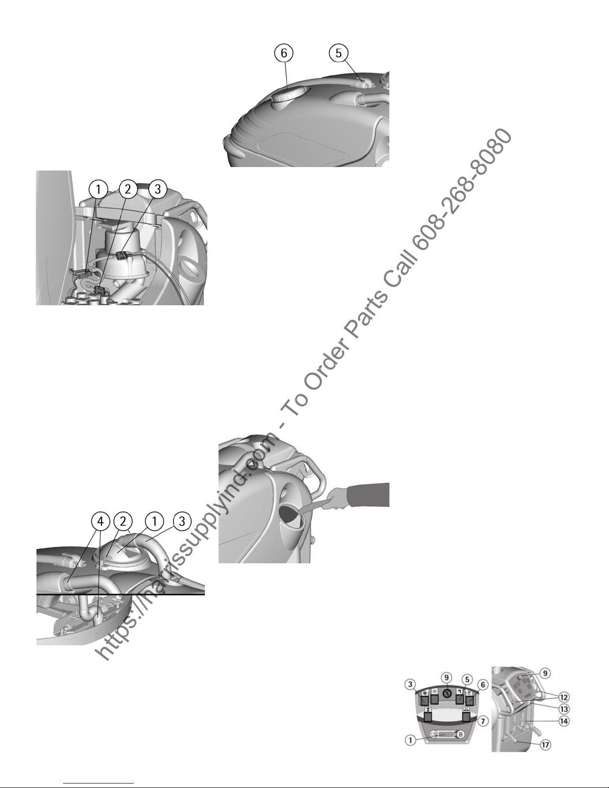
LEGEND INSTRUMENT BOARD AND CON-
https://harrissupplyind.com - To Order Parts Call 608-268-8080
TROLS
1. DISPLAY
2. SWITCH SPEED SELECTION
3. SWITCH SUCTION MOTOR
4. SIGNAL LAMP BRAKE ON
5. SWITCH SOLENOID VALVE/COMMUTATOR
3S SYSTEM (OPTIONAL)
6. SWITCH BRUSHES MOTOR
7. PUSH BUTTON UP/DOWN BRUSHES BASE
(only version with actuator)
8. PUSH BUTTON VISUALIZATION HOUR METER
9. SWITCH WITH KEY
10. INSTRUMENT BOARD
11. HANDLE BARS
12. LEVERS DRIVE CONTROL
13. PUSH BUTTON SECURITY DEVICE REVERSE MOTION
14. LEVER SOLUTION VALVE
15. LEVER BRUSHES BASE GROUP LIFTING
(only version with hydraulic pump)
16. LEVER PARKING / EMERGENCY BRAKE
17. LEVER SQUEEGEE LIFTING
5
Page 6
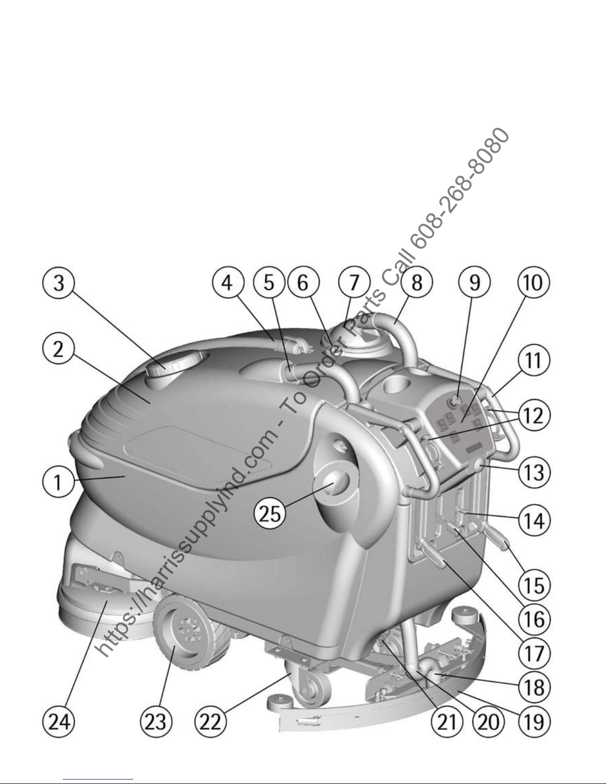
LEGEND MACHINE
https://harrissupplyind.com - To Order Parts Call 608-268-8080
1. SOLUTION TANK
2. RECOVERY TANK
3. RECOVERY TANK CAP
4. DRAIN HOSE PLUG
5. RECOVERY TANK SQUEEGEE HOSE COUPLING
6. SUCTION COVER LOCKING LEVERS
7. SUCTION COVER
8. SUCTION HOSE
9. KEY SWITCH
10. INSTRUMENT BOARD
11. HANDLE BARS
12. DRIVE CONTROL LEVERS
13. REVERSE MOTION SECURITY DEVICE PUSH
BUTTON
14. SOLUTION VALVE LEVER
15. BRUSH LIFTING LEVER (only version with
hydraulic pump)
16. PARKING / EMERGENCY BRAKE LEVER
17. SQUEEGEE LIFTING LEVER
18. SQUEEGEE HOSE COUPLING
19. SQUEEGEE ASSEMBLY
20. SQUEEGEE HOSE GUIDE SPRING
21. BRUSH PRESSURE ADJUSTMENT KNOB
22. CASTOR WHEELS
23. TRACTION WHEELS
24. BRUSH BASE
25. SOLUTION SCREW CAP
6
Page 7

TECHNICAL DESCRIPTION U/M BD 26 26
https://harrissupplyind.com - To Order Parts Call 608-268-8080
Cleaning width mm/in 660/26
Squeegee width mm/in 980/39
Working capacity, up to sqm/h, sqft/h 3000/32,291
Brushes diameter mm/in 2x345/2x13.5
Brushes rpm Rpm 190
Pressure on the brushes kg/lbs. 60 max/133 max
Brushes motor W/A 600/25
Traction motor W/A 400/13
Type of drive autom.
Movement speed 1st speed km/h/mph 3,5/3
Movement speed 2nd speed km/h/mph 5,0/2
Maximum gradient 10 %
Suction motor W/A 570/24
Suction vacuum mbar/inches of water 160/64
Solution tank l/gal 100/26
Recovery tank l/gal 105/28
Machine length mm/in 1670/660
Machine height mm/in 1195/47
Machine width (without squeegee) mm/in 730/29
Compartment of the batteries mm/in 415 x 520 x 385/ 16.5
x 20 x 15
Weight of the machine (empty and without batteries) kg/lbs. 190/420
Acoustic pressure level dB (A) 72
Class III
Protection level IP X3
Voltage V 24
7
Page 8

INTRODUCTORY COMMENT
https://harrissupplyind.com - To Order Parts Call 608-268-8080
Your new Tornado unit is a high
quality, precision-made product.
All parts used in the manufacturing of this unit have passed rigid
quality control standards prior to
assembly. Please safeguard the
original receipt / invoice. If you
experience any problems with your
unit during the warranty period,
the original receipt / invoice will
act as proof of purchase. Contact
Tornado for any warranty inquiries.
This oor-cleaning machine is used
for the industrial and commercial
cleaning and is able to clean any
type of oor. During its forward
movement, the combined action of
the brush and the solution removes
the dirt, which is recovered through
the rear suction assembly, giving a
perfectly dry surface.
The machine must be used only
for such purpose. It gives the best
performance if it is used correctly
and maintained in perfect working
order. We therefore ask you to read
this instruction manual carefully
whenever difculties arise in the
course of the machine’s use.
GENERAL RULES OF SECURITY
The rules below must be followed
carefully in order to avoid damages
to the operator and to the machine.
- Read the labels carefully on the
machine. Do not cover them for
any reason and replace them immediately if damaged.
- The machine must only be used
by authorized personnel which
have been instructed in its use.
- During the operation of the machine, pay attention to other people
and especially to the children.
- In case of danger immediately apply the emergency brake.
- Leaving the machine in parking
position, remove the key and apply
the parking brake.
- Do not mix different detergents,
avoiding harmful odours.
- Do not place any liquid containers
onto the machine.- Storage temperature: between -40°F and 131°F
(5°C and 55°C).
- Operating temperature: between
40°F and 104°F (5°C and 40°C).
- The humidity should be between
30 and 95%.
- Do not use the machine in explosive atmosphere.
- Do not use the machine as a
means of transport.
- Do not use acid solutions that
could damage the machine and/or
the persons.
- Do not use the machine on sur-
faces covered with inammable
liquids or dusts (for example hydrocarbons, ashes or soot).
- In case of re, use a powder re
extinguisher. Do not use water.
- Do not strike shelving or scaffoldings, where there is danger of
falling objects.
- Adapt the working speed to the
cleaning conditions.
- Do not use the machine on areas
having a higher gradient than the
one stated in the technical description.
- The machine has to carry out the
operations of washing and drying.
Different operations must be carried out in restricted areas prohibited to non-authorized personnel.
Signal the areas of moist oors
with suitable signs.
- If the machine does not work
properly, check by conducting
simple maintenance procedures.
Otherwise, ask for technical advice
from a authorized assistance center.
- Where parts are required, ask for
ORIGINAL spare parts from the
distributor and/or to an authorized
dealer.
- Use only ORIGINAL brush indicated in the paragraph “RECOMMENDED BRUSH “.
- For any cleaning and/or maintenance operation take off the power
supply from the machine.- Do
not take off any of the protections
that require the use of tools to be
removed.
- Do not wash the machine with
direct water jets or with highpressure water or with corrosive
material.
- Every 200 working hours have a
machine check through an authorized service department.
- In order to avoid scales in the
solution tank lter, only ll the
solution tank just prior to use.
- Before using the machine, check
that all panels and coverings are in
their position as indicated in this
use and maintenance manual.
- Be sure the recovery tank is
empty before lifting it.
- Restore all electrical connections
after any maintenance operation.
- Provide for the scrapping of the
material of normal wear following
strictly the respective rules.
- When your machine has to stop
activity, provide for the appropriate waste disposal of its materials,
especially oils, batteries and electronic components, and considering
that the machine itself has been,
where possible, constructed using
recyclable materials.
8
Page 9

GROUNDING INSTRUCTIONS
https://harrissupplyind.com - To Order Parts Call 608-268-8080
This appliance must be grounded. If it should malfunction or breakdown, grounding provides a path of least
resistance for electric current to reduce the risk electric shock. This machine is equipped with a cord having an
equipment -grounding conductor and grounding plug. The plug must be inserted into an appropriate outlet that
is properly installed and grounded in accordance with all local codes and ordinances.
WARNING: Improper connection of the equipment-grounding conductor can result in a risk of electric shock.
Check with a qualied electrician or service person if you are in doubt as to whether the outlet is properly
grounded. Do not modify the plug provided with the appliance - if it will not t the outlet, have a proper outlet
installed by a qualied electrician.
This appliance is for use on a nominal 120-volt circuit, and has a grounding plug that looks like the plug
illustrated in sketch A.
9
Page 10

Symbol denoting the solu-
https://harrissupplyind.com - To Order Parts Call 608-268-8080
tion valve.
Indicates the solution
valve lever. Indicates the
signal lamp of the solenoid valve functioning.
Symbol denoting the
brush.
Indicates the switch of
thebrush motor.
Symbol denoting the suction motor.
Indicates the switch of
thesuction motor.
Symbol denoting up –
down of the squeegee.
Indicates the squeegee
lever.
Symbol denoting the
selection switch of the
driving speed.
Symbol that indicates the
lever for the brush base
lifting or the push button
up/down brush base.
Symbol denoting the
brake.
Indicates the signal lamp
of the brake on.
Symbol denoting the
brake.
Indicates the lever of the
emergency and parking
brake.
Symbol denoting the
crossed bin. Indicates that
at the end of its activity,
the machine has to be
disposed conforming to
the laws in force.
Symbol denoting the open
book.
Indicates that the operator has to read the manual
before the use of the machine.
Warning symbol.
Read carefully the sections marked with this
symbol, for the security
of both the operator and
the machine.
Symbol denoting the
charge level of the batteries.
Symbol denoting the hour
meter.
Indication of the maximum temperature of the
solution detergent.
It is placed near the charging hole of the solution
tank.
10
Page 11

BEFORE USE
https://harrissupplyind.com - To Order Parts Call 608-268-8080
Handling of the packed machine
The machine is supplied with suitable packing foreseen for forklift
truck handling.
The total weight is 562 lbs.
(255kg).
Packing dimensions:
Base: 70” x 37” (178 cm x 93 cm)
Height: 55” (138 cm)
ATTENTION:
Do not place more than 2 units on
top of each other.
Unpacking of the machine
1. Remove the external packing.
2. Unscrew the brackets (1and2)
that secure the machine to the pallet.
Access to the battery compartment
In order to reach the battery compartment, it is necessary to lift the
recovery tank (1) forward.
Before lifting it, it is necessary to:
1. Bring the machine on a level
surface.
2. Take off the squeegee hose (2)
from its seat.
3. Take off the suction cover (4)
after turning the locking levers (3).
4. Remove the lter and its cover
to make sure that the tank is empty,
otherwise, proceed to empty the
tank as indicated under paragraph
“RECOVERY TANK CLEANING”.
the support of the gas shock absorber (1).
7. Reassemble everything.
Battery installation and setting of
the battery type
The machine is equipped either
with batteries in serial connection
or elements of DIN-type assembled
together and connected in series,
placed in its appropriate compartment under the recovery tank and
must be handled using suitable
lifting equipment (due to weight,
considering the type of batteries
chosen, and coupling system).
The batteries must be in accordance
with CEI 21-5 Norms.
3. Move the machine backwards,
avoiding heavy contacts to mechanical parts.
4. Keep the pallet and the brackets
for future transport.
The machines at 24V will t into
the appropriate reduced steel basin.
5. Lift the tank by pulling up on the
rear handle until the gas shock absorber (1) engages, which lifts it up
to the open position. By lifting the
tank further, the maximum opening
position can be obtained.
6. To close the battery compartment, push the tank down if it is
open at the open position, If the
tank is open to the maximum position it is necessary to unlock
11
Page 12

ATTENTION:
https://harrissupplyind.com - To Order Parts Call 608-268-8080
The machine and its battery check
card foresee the use of traditional
lead batteries.
CHECK SETTING OF THE
CHECK CARD ON THE INDICATOR (1) (see under paragraph
"BATTERIES CHARGE LEVEL
INDICATOR").
In case of GEL batteries installation, it is necessary to set the battery check card. Please contact the
authorized technical assistance.
ATTENTION:
Strictly follow all manufacturer/
distributor directions for the maintenance and charging of the batteries. Special staff, using suitable
protection accessories must execute
all installation and maintenance
operations.
For batteries installation it is necessary to reach the battery compartment as indicated under paragraph
“ACCESS TO THE BATTERY
COMPARTMENT”.
1. Open the recovery tank up to the
maximum opening position.
2. Place the batteries in the compartment.
3. Connect the terminals, paying
special to the polarities, avoiding
contact with other parts that could
create short circuit.
Battery charger
Be sure that the battery charger is
suitable for the installed batteries
both for their capacities and type
(lead/acid or GEL and equivalent).
Batteries charging
To charge the batteries it is necessary to reach the battery compartment as indicated under paragraph
“ACCESS TO THE BATTERY
COMPARTMENT”.
1. After disconnecting the batteries
from the unit, plug in the batteries
connector (1) placed in the inner
part of the machine, to the connector (3) of the battery charger.
2. Proceed with the charging keeping the tank lifted.
ATTENTION:
Never charge a GEL battery with a
non-gel charger. Strictly follow the
instructions supplied by the batteries and charger manufacturer.
To prevent permanent damage to
the batteries, it is necessary to
avoid their complete discharge Batteries must be charged within a few
minutes after the battery discharge
signal starts blinking.
NOTE: Never leave batteries
completely discharged even if the
machine is not used. If using wet
lead batteries, please check the
electrolyte level every 2 weeks and
add distilled water as needed.
ATTENTION:
When charging the batteries it is
necessary to follow all directions
given by the manufacturer and/or
the distributor. Only qualied staff
must carry out all the installation
and maintenance operations. When
charging batteries there is a danger
of gas exhalations and emission
of corrosive liquids. There is also
a danger of re, do not approach
with open ames.
Batteries disposal
It is mandatory to hand over ex-
hausted batteries, classied as
dangerous waste, to an authorized
institution according to the current
laws.
Batteries charge level indicator
TURNING THE KEY (9) CLOCKWISE, ON THE DISPLAY (1)
WILL CAUSE TO APPEAR, IN
SEQUENCE, THE FOLLOWING
INFORMATION:
1. The version (for example A003)
of software installed on the machine.
2. The setting of the battery check
card which can be for the 24V version:
GE 24: check card set for GEL batteries.
Pb 24: check card set for lead batteries.
12
Page 13

3. The batteries charge level indica-
https://harrissupplyind.com - To Order Parts Call 608-268-8080
tor (1) is digital. The battery charge
level starts at 90, which indicates
the 90% of the total charge and
decreases by 10’s. When the charge
level reaches 20%, the display
starts blinking, and you are near the
end of work time.
ATTENTION:
After a few seconds of the four
lines, the brush motor stops automatically. With the remaining
charge it is possible to nish the
drying operation before proceeding
to the recharge station.
Squeegee assembly
1. Hold the squeegee support (1)
slightly off of the oor.
2. Insert the two stud bolts (3)
placed on the upper part of the
squeegee (2) inside the slots on the
support.
3. Lock the squeegee by rotating
the lever (4) clockwise.
4. Insert the squeegee hose (5) into
its coupling on the squeegee assembly.
If the lower part of the rubber is
bent too much
Take off the pressure rotating the
wing nut (6) counterclockwise.
If the lower part of the rubber is not
bent enough
Increase the pressure rotating the
wing nut (6) clockwise.
Hour meter
The machine is equipped with an
hour meter located in the same
display as the battery charge level
indicator (1). Keeping the button (8) pressed for more than 3
seconds, will display the working
hours. Continue holding and after
a few seconds the working minutes
are shown.
Adjustment of the squeegee
In order to have a perfect drying
result by the squeegee, the rear
rubber must have the lower bending uniformly adjusted across its
full length. For the adjustment, it
is necessary to put the unit in an
operating mode, the suction motor
has to be switched on and the brush
have to function together with the
solution.
If the bending is not uniform across
the whole rubber
Adjust the squeegee inclination by
rotating counterclockwise the wing
nut (7) to increase the bending in
the central part, or clockwise to
increase the bending on the extremities.
Height adjustment
Once the pressure and inclination
of the squeegee have been adjusted,
it is necessary to maintain this
optimum condition by making the
wheels slightly touch the oor. Rotate the at knob (8) counterclock-
wise to lower the wheels or clockwise to raise them. Both wheels
must be adjusted in the same.
13
Page 14

in their slots; rotate the brush to
https://harrissupplyind.com - To Order Parts Call 608-268-8080
push the button towards the coupling spring until they are locked in
place.
The gure shows the rotating direction for brush coupling.
ATTENTION:
Every type of oor requires a
specic adjustment. For example,
concrete oors (where the friction
tends to be high) need little pressure, while smooth oors (ceramics) need higher pressure.
If the cleaning operations are
always made on the same type of
oor, the adjustment can change
only as the rubbers wear.
Splash guard assembly
The two splashguards have to be
assembled onto the brush base
group. Insert the metal strips inside
the suitable slots on the rubber.
Place the round hole at the at
end of the strip onto the screw
(1) placed in the front part of the
brush base group. Secure the strips
through the nut locking it.
Lock the coupling levers (2) in the
rear part of the brush base group to
the rings placed at the ends of the
metal strips still free. Repeat for the
other splashguard. Ensure that the
gap between the two rubbers in the
front part of the brush base group is
to reduced to a minimum.
With brush assembled, the splash-
guard must slightly touch the oor.
Brush assembly
The machines that have the electrical brush base lifting:
1. Switch on the machine by turning the key (9) clockwise.
2. Press the push button (7) of up/
down brush base to lift the brush.
3. Turn off the unit by turning the
key (9) counterclockwise
ATTENTION:
To carry out brush assembly operations with the electric supply on,
may cause damages to hands.
With the brush base group in lifted
position, insert the brush into their
plate seat underneath the brush
base turning them until the three
metal buttons are properly seated
We suggest to daily alternate the
brush position for a longer brush
life. Whenever a brush becomes
deformed, we suggest installing
them in the same position. This will
avoid motor overload or vibrations
from the different inclination of the
bristles.
ATTENTION:
Use only brush supplied with the
machine or the ones indicated in
the paragraph “RECOMMENDED
BRUSH”. The use of other brush
can compromise security.
Floor Cleaning
Connecting the batteries to the
machine Once the battery charging
has been completed:
1. Disconnect the connector (3)
from the battery charger (1).
14
Page 15
To do this, it is necessary to reach
https://harrissupplyind.com - To Order Parts Call 608-268-8080
the battery compartment as indicated under paragraph “ACCESS
TO THE BATTERY COMPARTMENT”.
2. Connect the machine connector
(2) to the batteries.
3. Close the battery compartment.
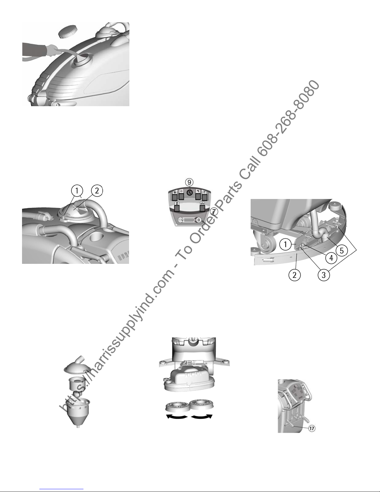
Recovery tank
Check that the cover of the suction
lter (1) is correctly secured, after
rotating the levers (2) and that the
suction motor hose (3) is correctly
connected to it.
Verify also that the squeegee hose
couplings (4) are correctly inserted
into the seats, that the exhaust hose
plug (5) placed in the front part of
the machine is closed and that the
inspection cap (6) is closed as well.
DETERGENT SOLUTION TANK
The capacity of the detergent solution tank is indicated in the technical data.
Open the screw plug placed in the
rear left part of the machine and
ll the detergent solution tank with
clean water at a maximum temperature of 50°C. Add the liquid detergent in the percentage and conditions foreseen by the manufacturer.
To avoid excessive foam presence,
which could cause problems to the
suction motor, use the minimum
percentage of detergent. Screw
down the plug to close the tank.
ATTENTION:
Use always low foam detergent. To
avoid foam pres¬ence, before starting working operation, introduce
into the recovery tank a minimum
quantity of anti-foam product.
Never use pure acid.
STARTING OF THE MACHINE
1.Turn the key (9) clockwise.
2.Check the battery type and the
charge level on the display (1).
3.Press the brushes motor switch
(6).
4.Press the suction motor switch
(3).
5.Press the solenoid valve switch
(5).
6.Lower the brushes base onto the
oor.
The machines which have the electrical brushes base lifting press the
push button (7) of up/down of the
brushes base.
7.Acting upon the solution valve
lever (14) open and adjust the de-
tergent solution ow.
The water starts to ow automati-
cally acting upon the levers drive
control (12). On the instrument
board the indicator of the solenoid
valve switch (5) will turn on. Re-
leasing these levers, the ow will
stop.
8.Acting upon the squeegee lifting
lever (17) lower the squeegee.
9.Acting upon the levers drive
control (12) the machine starts to
move, the brushes start to rotate
and the squeegee starts to dry.
10.During the rst metres/feet,
check that the squeegee adjustment
guarantees a perfect drying action
and that the detergent solution ow
is appropriate. It has to be sufcient
to wet the oor uniformly avoid-
ing the leakage of detergent from
the splash guards. Always consider
that the correct quantity of solution
detergent depends on type of oor,
dirtiness and machine speed.
15
Page 16

Forward movement
https://harrissupplyind.com - To Order Parts Call 608-268-8080
The traction of the machine is
given through an electronically
controlled motor.
To move the machine, turn the key
(9) clockwise, then rotate the drive
control levers (12) placed on the
handle bar, when pressed forward
you activate the forward drive,
when pulled backwards the reverse
movement is activated. The control
acts in a progressive way, the
further the levers are pushed the
faster the unit goes, therefore it is
possible to graduate the speed
depending on the job requirement
by rotating the lever to whatever is
necessary. When going in reverse
the speed is reduced.
Speed adjustment
Two values of the maximum drive
speed in forward movement can be
chosen. Press the switch forward
for fast speed and rearward for
slow speed.
Set the desired speed through the
speed selection switch (2).
A large-sized push button (13),
placed on the rear of the machine
is for the automatic drive reversal.
If the operator unintentionally
remains blocked between the
machine and an obstacle, this push
button forces the control to reverse
the machine when it touches the
operator.
Working brake
To stop the machine during normal
working situation, it is sufcient to
release the drive control levers
(12), as the machine is equipped
with an electronic braking system.
The brush and the solution ow
stop automatically.
Emergency brake
In case of an emergency, and
immediate stop can be made by
pushing down on the lever of the
emergency and parking brake (16).
Adjustment of the brush pressure
Through the knob (1) it is possible
to adjust the brush pressure on the
cleaning surface.
By turning the knob clockwise the
pressure increases, rotating it
counterclockwise, decreases the
pressure.
This device allows a more efcient
cleaning action on very difcult
and dirty surfaces.
The control of the adjustment of
the brush pressure is possible
through a sliding indication. It’s
position shows the value indicated
on the label placed in
correspondence of the slots where
it slides.
On the 24-Volt machines the
indicator is placed in the rear part
of the frame inside the battery
compartment.
ATTENTION:
When moving the machine
backwards, make sure that the
squeegee is lifted.
Security device reverse movement
ATTENTION:
This control locks the machine
immediately. The emergency brake
also functions as a parking brake.
To start to work again, release the
lever by unlocking the parking
button on the lever itself and
pushing on the drive control levers
(12).
16
ATTENTION:
In order not to overload the brush
motor, reduce the brush pressure
going from smooth oors to rough
ones (ex. concrete).
Page 17

Brush motor overload protection
https://harrissupplyind.com - To Order Parts Call 608-268-8080
device
The machine is equipped with a
protection device for the brush
motor. This device locks the motor
functioning in order to protect it
and indicates the overload on the
display (1) with ”AL01”.
Excessive brush pressure on a
rough oor could cause the lock.
Check the brush pressure
adjustment as indicated in the
previous paragraph.
ATTENTION:
To restore the functioning of the
brush motor, turn off and on again
the machine by using the key
switch (9).
Overow device
In order to avoid serious damage to
the suction motor, the machine is
equipped with a oat that closes
the suction hose and stops the
suction when the recovery tank is
full,
When this happens, it is necessary
to empty the recovery tank.
1. Hold the exhaust hose in front
of the machine.
2. Take off the exhaust plug by
pulling up its lever and empty the
recovery tank into appropriate
containers, according to the
standard norms.
ATTENTION:
This operation must be carried out
using gloves to protect from
contact with dangerous solutions.
Stopping the machine
Before executing any type of
maintenance:
1. Turn the brush motor switch off
(6).
2. Turn the suction motor switch
off (3).
3. Lift the brush base from the
oor.
For machines that have the
electrical base brush lifting, press
the push button (7) of up/down of
the brush base switch.
4. Lift the squeegee pulling up on
the lever (17).
5. Bring the machine to an
appropriate place for draining the
tanks.
6. Turn the key (9)
counterclockwise.
7. Apply the parking brake (16).
Daily maintenance
Recovery tank cleaning
1. Hold the exhaust hose in front
of the machine.
2. Take off the plug of the exhaust
hose by pulling its lever and empty
the recovery tank into appropriate
containers.
3. Take off suction cover after
rotating the locking levers.
4. Take off the lter and lter
protection.
5. Take off the inspection cap of
the recovery tank.
6. Rinse the tank with a water jet
from both openings.
17
Page 18
ATTENTION:
https://harrissupplyind.com - To Order Parts Call 608-268-8080
This operation must be carried out
using gloves to protect from
contact with dangerous solutions.
Suction lter cleaning
1. Take off suction cover (2) after
rotating the locking levers (1).
Brush cleaning
Disassemble the brush and clean
them with a water jet (check under
paragraph of “BRUSH
DISASSEMBLY”).
Brush disassembly
For machines that have the
electrical base brush lifting:
1. Switch on the machine by
turning the key (9) clockwise.
2. Press the push button (7) of
up/down brush base to lift the
brush.
3. Remove the electric supply by
turning the key (9)
counterclockwise.
ATTENTION:
Pick up the brushes and wash them
using gloves to protect from
contact with dangerous solutions.
Squeegee cleaning
Keeping the squeegee clean
guarantees the best drying action.
For cleaning it is necessary to:
1. Take off the squeegee hose (5)
from the coupling.
2. Disassemble the squeegee (2)
from its support (1) by rotating the
lever (4) counterclockwise and
sliding the squeegee to the right to
release the stud bolts (3) from their
slots.
3. Clean with care the internal part
of the squeegee inlet and rubbers.
4. Reassemble all parts.
2. Take off the lter and lter
protection.
3. Clean all parts with a water jet
especially the inside surfaces and
the lter bottom. 4. Reassemble all
parts.
ATTENTION:
To carry out brush disassembly
operations with the electric supply
on, may cause damages to hands.
With the base brush in lifted
position, turn the brush as
indicated in the gure, until it is
released from the brush holder
plate seat. The gure shows the
direction for brush release.
Weekly maintenance
Rear squeegee rubber check
Check the squeegee rubber wear
and eventually turn or replace it.
For the replacement it is necessary
to:
1. Lift the squeegee assembly by
pulling up on the lever (17).
18
Page 19

2. Release the hook (9) of the
https://harrissupplyind.com - To Order Parts Call 608-268-8080
rubber blade holder and take the
rubber off.
3. Turn the rubber to a new side or
replace it.
To reassemble the squeegee,
reverse the operations above
inserting the rubber on the guides
and locking it with the rubber
blade holder.
Squeegee hose cleaning
Weekly, or in case of insufcient
suction, it is necessary to check
that the squeegee hose is not
clogged. To clean it, proceed as
follows:
1. Take off the hose (1) from the
squeegee coupling.
2. Wash the inside of the hose
with a water jet.
To reassemble the hose reverse the
operations above.
ATTENTION:
Do not wash the hose that goes
from the suction motor to the
suction cover while it is connected
to the suction motor connection.
Cleaning of the solution tank
1. Bring the machine to an
appropriate place for the solution
draining.
2. Unscrew the solution tank cap.
3. Unscrew the solution drain cap
(1).
4. Allow the solution to ow out
into appropriate containers.
Pay close attention not to lose
the gasket of the cap.
5. Rinse the solution tank with a
water jet.
6. Reassemble all parts.
ATTENTION:
This operation must be carried out
using gloves to protect from
contact with dangerous solutions.
Cleaning of the solution lter
1. Empty the solution tank as
indicated in paragraph
“CLEANING OF THE
SOLUTION TANK”.
2. Unscrew the cap of the exhaust
lter (1).
3. Rinse the lter placed inside the
cap, paying close attention not to
lose the gasket of the cap.
4. Rinse the hose by pouring some
water into the solution tank.
5. Reassemble all parts.
ATTENTION:
This operation must be carried out
using gloves to protect from
contact with dangerous solutions.
Two-month maintenance
Front squeegee rubber check
Check the wear of the front
squeegee rubber replace it when
needed.
For the replacement it is necessary
to:
Release the squeegee from the
support as indicated in paragraph
"SQUEEGEE CLEANING".
Unscrew the wing nuts in the front
part of the squeegee.
Take off the rubber holder blade.
Replace the front rubber. Reassemble all parts.
Six-month maintenance
Splash guard rubber check
1. Open the hooks in the rear part
of the brush base group from the
slot placed at the end of the metal
strip.
2. Replace the splashguard
rubbers and follow assembling
instructions as under paragraph
“SPLASH GUARD
ASSEMBLY”.
With brush assembled, the
splashguard must slightly touch the
oor.
19
Page 20

Cleaning of the inner lter solution
https://harrissupplyind.com - To Order Parts Call 608-268-8080
tank
Regularly clean the internal lter
of the solution tank that is in the
rear lower part of the machine.
Empty the solution tank, and
remove the tting of the water
outlet by taking off the two screws
that x it to the tank. Clean the
inside part of the tting. Pour
some water into the tank to clean
it. Reassemble the tting onto the
solution tank.
Check of the brake
Check the braking efciency and
ensure that both pads (1) have a
distance of not more than 3mm
from the wheels, in the resting
position. If necessary, adjust them
through the adjusting nuts (2).
Troubleshooting guide
The suction motor does not work
1. Verify that the key switch (9) is
in the on position.
2. Check the charge level of the
batteries on the display (1).
3. Check that the battery
connector is correctly plugged in.
4. Verify that the switch (3) is on.
5. Check that the red connector of
the suction motor is plugged in
correctly.
If the problem persists, please
contact the authorized technical
assistance.
The traction motor does not work
1. Switch the machine off and on
again.
2. Release the brake (16) until the
signal lamp (4) comes off.
3. Push on the drive control levers
(12).
If the problem persists, please
contact the authorized technical
assistance.
All other checks should be made
by an authorized technical service
center.
The brush motor does not work
1. Verify that the key switch (9) is
in the on position. Switch the
machine off and on again. 2. Check
the charge level of the
batteries on the display (1).
3. Check that the battery
connector is plugged in correctly.
4. Verify that the switch (6) is on.
5. Push on the drive control levers
(12).
6. Check that on the display (1)
does not appear the alarm “AL01”
(brush motor overload alarm).
If the problem persists, please
contact the authorized technical
assistance.
20
ATTENTION:
Never leave the batteries
discharged for an extended period
of time.
The solution on the brush is not
sufcient
1. Check that the solution valve
lever (14) is open.
2. Check the level of the liquid in
the solution tank.
Page 21

3. Check that solution lter is
https://harrissupplyind.com - To Order Parts Call 608-268-8080
clean (see under paragraph
“CLEANING OF THE
SOLUTION FILTER”).
4. The machine is equipped with
solenoid valve, therefore push the
drive control levers (12) to let the
solution come down and check that
the signal lamp (5) comes on.
5. If the solution still does not
come down, clean the lter inside
the solution tank. Empty the
solution tank. Remove the tting
of the water outlet by taking off
the two screws that attach it to the
tank. Clean the inside lter part of
the tting. Pour some water into
the tank and clean it. Reassemble
the tting onto the solution tank.
If the problem persists, please
contact the authorized technical
assistance.
The machine does not clean
properly
1. The brushes do not have the
suitable bristle dimension: contact
the authorized technical assistance.
2. The brushes have got worn
bristles. Check the brushes wear
condition and eventually replace
them (the brushes have to be
replaced when the bristles have
reached a height of about ½” or
15mm).
To replace brush, see instructions
at paragraph “BRUSH
DISASSEMBLY” and “BRUSH
ASSEMBLY”.
3. The solution is insufcient:
further open the solution valve.
4. Check that the detergent is in
the recommended percentage.
5. Increase the brush base pressure
(see at paragraph "ADJUSTMENT
OF THE BRUSH PRESSURE").
Contact the authorized technical
assistance for advice.
The squeegee does not dry
perfectly
1. Check that the squeegee
rubbers are clean.
2. Check the adjustment of the
height and the inclination of the
squeegee (see section
“ADJUSTMENT OF THE
SQUEEGEE” in “BEFORE
USE”).
3. Check that the suction hose is
correctly inserted in the proper seat
on the recovery tank.
4. Clean the suction lter.
5. Replace the rubbers if worn out.
6. Check that the suction motor
switch is on.
Excessive foam production
Check that low foam detergent has
been used. Add small quantities of
anti foam liquid into the recovery
tank.
Please be aware that a bigger
quantity of foam is produced when
the oor is not very dirty. In this
case please dilute detergent
solution.
21
Page 22

PROGRAMMED MAINTENANCE
https://harrissupplyind.com - To Order Parts Call 608-268-8080
INTERVENTION DAILY 20 HOURS * 200 HOURS * 1000 HOURS *
RECOVERY TANK CLEANING •
SUCTION FILTER CLEANING •
SOLUTION TANK FILTER CLEANING •
BRUSHES CLEANING •
BRUSHES DISASSEMBLY AND CLEANING •
SQUEEGEE CLEANING •
FRONT SQUEEGEE RUBBER REPLACE-
MENT
REAR SQUEEGEE RUBBER REPLACEMENT •
SPLASH GUARD RUBBER REPLACEMENT •
CHECK SQUEEGEE ADJUSTMENT •
SQUEEGEE HOSE CLEANING •
SOLUTION TANK CLEANING •
CHECK BATTERIES ELECTROLYTE •
CHECK OF THE BRAKE •
TRACTION MOTOR CHECK •
BRUSHES MOTOR CHECK •
SUCTION MOTOR CHECK •
CHECK BRUSHES BASE GROUP •
SCREW TIGHTENING •
* The hours refer to the ones indicated on the display (see under paragraph ”HOUR METER").
•
RECOMMENDED BRUSH
Brush must be chosen depending on type of oor and dirt to be removed. The employed material and the bristle
diameter are the elements that distinguish different types of brush.
MATERIAL CHARACTERISTICS
PPL (Polypropylene) Good wear resistance. Maintains a characteristic with hot water up to 140°F (60°C). It is
not hygroscopic.
NYLON Excellent wear resistance, even with hot water over 60°C. It is hygroscopic. It looses its physical
characteristics over time.
TYNEX Nylon bristles with grains of abrasive material. Use with caution in order not to mark the oor or ruin
the polishing.
BRISTLES THICKNESS Thicker bristles are more rigid and must be used on smooth oor or oor with small
joints. On irregular oors with deep joints or relieves, it is recommended to use softer bristles which penetrate
more easily and deeper. Please be aware that when brush bristles are worn out and therefore too small, they
become rigid and unable to penetrate and clean deeper. This may also happen with thicker bristles creating
brush vibration.
PAD HOLDER It is equipped with anchor points that permit the locking of the abrasive pad. The pad is rec-
ommended to clean smooth oors.
22
Page 23

MACHINE CODE QTY DESCRIPTION USE
https://harrissupplyind.com - To Order Parts Call 608-268-8080
BD 26 26 48903010 2 Brush PPL 0,3 Ø 345/13in Delicate oors.
48903020 2 Brush PPL 0,6 Ø 345mm/13in Normal oors.
48903030 2 Brush PPL 0,9 Ø 345mm/13in Smooth oors with small
joints and persistent dirt.
48903040 2 Brush TYNEX Ø 345mm/13in Floors of resistant material
and particularly dirty.
48903050 2 Brush 5-mix Ø 345mm/13in For all types of oors.
48903060 2 Brush nylon 0,6 Ø 345mm/13in orange Delicate oors.
48803010 2 Pad holder Ø 330/13 in. For pads of 14”, for smooth
surfaces cleaning.
48803030 2 Pad holder Ø 330/13 in. + center lock green For pads of 14”, for smooth
surfaces cleaning.
48803040 2 Pad holder Ø 330/13in. + center lock black For pads of 14”, for smooth
surfaces cleaning.
23
Page 24

Please provide additional information on
https://harrissupplyind.com - To Order Parts Call 608-268-8080
Warranty
Registration
Form
Tornado equiptment: (Check choices below)
__ Automatic Scrubbers __Sweepers
__Propane Floor Machines __Rotary Floor Machine
__High Speed Burnishers __Carpet Vacuums
__Carpet Extractors & Spotters __Wet/Dry Vacs
__ Steam Cleaners __Jumbo Vacs
__Ride-On Equiptment __Pressure Washers
See complete product info at www.tornadovac.com
Selling Dealer:(Required)__________________________
Please Print Clearly
_____________________________________________________________________________
Company/Institution
_____________________________________ ____________________________________
Contact Name Title
_____________________________________ ____________________________________
Address City/State/Zip Code
_____________________________________ ____________________________________
Phone Fax
_____________________________________ ____________________________________
Date of Purchase Email
See white metal plate or sticker on unit for this information.
MACHINE TYPE/MODEL NUMBER: MACHINE SERIAL NUMBER:
1. 1.
2. 2.
3. 3.
4. 4.
Facility Description (please circle all that apply)
1. School 9. Hospital 17. U.S. Govt.
2. Retail Store 10. Nursing Home 18. Other Govt.
3. Restaurant 11. Religious Institution 19. Auto Service
4. Ofce Building 12. Airport 20. Airport
5. Contract Cleaning 13. Warehouse 21. Non-Prot
6. Light Manufacturing 14. Apartment/Condo 22. Other (specify)
7. Heavy Manufacturing 15. Warehouse
8. College/University 16. Supermarket
How did you rst lean about
Tornado cleaning and
maintenance equipment?
o Contacted by local dealer
o Previous experience with
Tornado products
o Reputation/
Recommendation
o Advertising
o Direct mail
o Internet
o Other
Total Hard Floor Area
o 0-10,000 (0-930)
o 10-50,000 (930-4,650)
o 50-250,000 (4,650-23,250)
o Over 250,000 (over
23,260)
In square feet (meters)
Total Carpeted Area
Square feet (square meters)
o 0-10,000 (0-930)
o 10-50,000 (930-4,650)
o 50-250,000 (4,650-23,250)
o Over 250,000 (over
23,260)
Damage or defect arising from abuse, neglect or other misuse is excluded from this warranty. Other items
may or may not apply based on your specic machine. If any defect occurs, the warranty is voided if
service is attempted by non-Authorized Tornado Service Centers.
©2015 Tornado Industries. All rights reserved.
X8449-TOR 1/2015
Return to:
Tornado Industries
333 Charles Ct. Unit 109
West Chicago, IL 60185
Fax: (630)818-1301
24
 Loading...