

Page 1
CAUTION – READ THESE INSTRUCTIONS BEFORE USING THIS MACHINE
TORNADO INDUSTRIES, LLC
333 CHARLES COURT
WEST CHICAGO, IL 60185
(630)-818-1300 FAX (630)-818-1301
WWW.TORNADOVAC.COM
Operations & Maintenance Manual
For Commercial Use Only
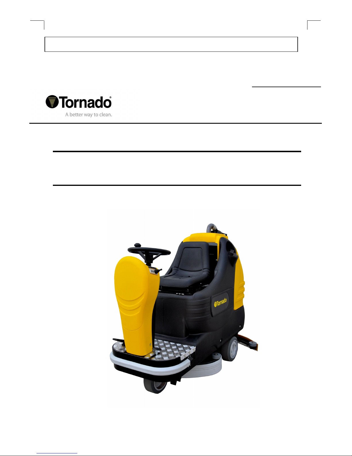
BD 26/27 RIDE ON SCRUBBER
MODEL NO: 99770
Form No. L3456A
©Tornado INDUSTRIES, LLC. All rights reserved
Page 2

SUMMARY 1
LEGEND PANEL OF CONTROLS 4
LEGEND MACHINE 4
TECHNICAL DESCRIPTION 5
INTRODUCTION 6
GENERAL RULES OF SECURITY 6
SYMBOLS 6
BEFORE USE 7
Handling packed machine 7
Unpacking the machine 7
Access to the battery compartment 7
Battery installation 7
Battery charger 7
BatterY charging 8
Batteries disposal 8
Connecting the batteries' connector and switching on the machine 8
Battery charge level indicator 8
Setting the battery check card 8
Hour meter 9
Squeegee assembly 9
Squeegee adjustment 9
Splash guard assembly 9
assembling the brushes 10
FLOOR CLEANING 10
Recovery tank 10
Detergent solution tank 10
STARTING THE MACHINE 10
Forward and backward movement 11
Horn 11
Working brake 11
Emergency brake 11
Automatic squeegee lifting when going backwards 11
Working in automatic mode 11
Working in manual mode 12
Working adjustments 12
Flow adjustment of the detergent solution 12
Brush pressure adjustment 12
Electric protection 13
Overflow device 13
STOPPING THE MACHINE AFTER CLEANING 13
DAILY MAINTENANCE 13
Emptying and cleaning the recovery tank 13
Cleaning the vacuum filter 14
Cleaning the brushes 14
Cisassembling the brushes 14
Cleaning the squeegee 14
WEEKLY MAINTENANCE 14
Rear squeegee rubber check 14
Squeegee hose cleaning 14
Cleaning the solution tank and the outer filter 14
TWO-MONTHLY MAINTENANCE 15
Front squeegee rubber check 15
SIX-MONTHLY MAINTENANCE 15
Splash guard rubber check 15
Cleaning the inner filter OF THE solution tank 15
CheckING the brakes 15
TROUBLESHOOTING GUIDE 15
The VACUUM motor does not work 15
The brush motor does not work 15
The traction motor does not work 15
The water does not come down onto the brushes or is insufficient 16
The machine does not clean properly 16
The squeegee does not dry suffiently 16
Excessive foam production 16
PROGRAMMED MAINTENANCE 17
RECOMMENDED BRUSHES 17
3
Page 3
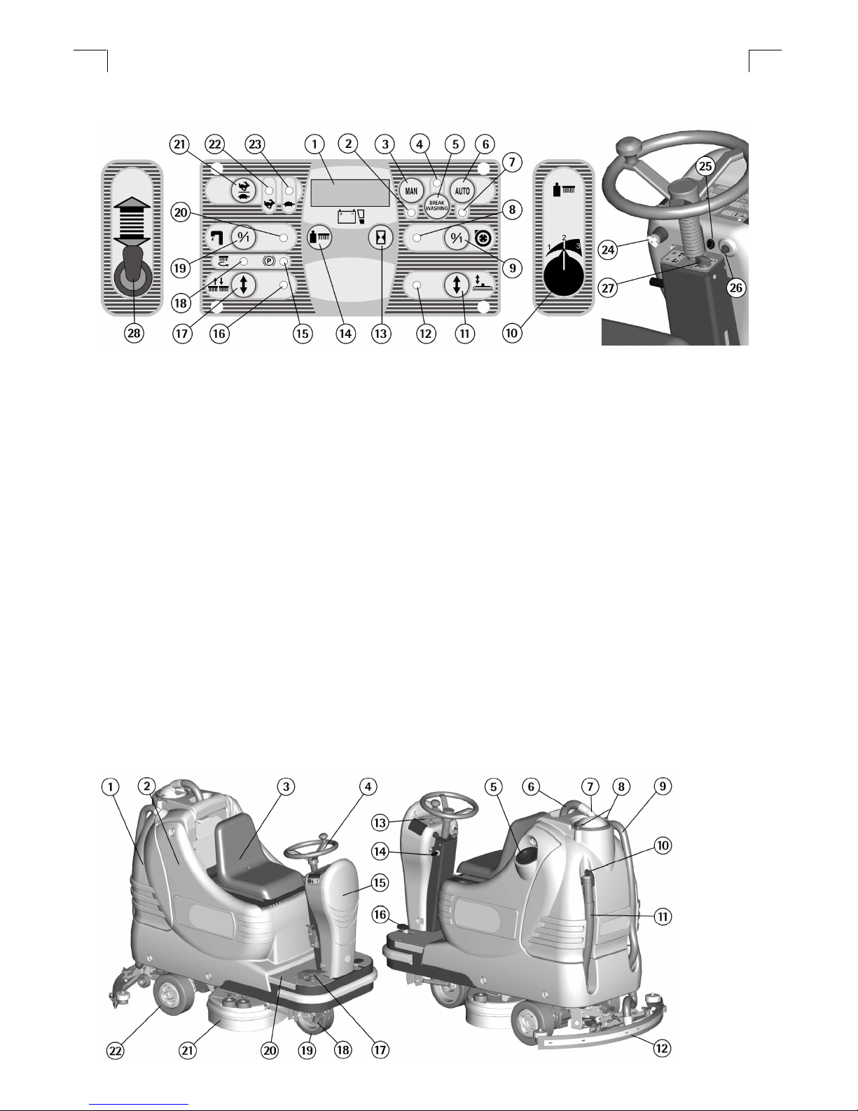
LEGEND PANEL OF CONTROLS
1. Display
2. Signal Lamp Manual Mode On
3. Push Button For Manual Mode
4. Signal Lamp Mode Break Washing On
5. Push Button For Break Washing Mode
6. Push Button For Automatic Mode
7. Signal Lamp Automatic Mode On
8. Signal Lamp Vacuum Motor On
9. Switch For Vacuum Motor
10. Adjustment Knob For Brush Pressure
11. Push Button To Raise/Lower Squeegee
12. Signal Lamp Squeegee Raise/Lower
13. Push Button Visualization Hour Meter (Display)
14. Push Button Visualization Brushes Pressure Set (Display)
LEGEND MACHINE
1. Recovery Tank
2. Solution Tank
3. Seat
4. Steering Wheel
5. Screw Cap For Solution Tank
6. Vacuum Hose
7. Vacuum Cover
8. Blocking Levers Vacuum Cover
9. Squeegee Hose
10. Recovery Tank Drain Hose Plug
11. Recovery Tank Drain Hose
15. Signal Lamp For Parking Brake On
16. Signal Lamp Brushes Raise/Lower
17. Push Button Raise/Lower Brushes
18. Signal Lamp Starting Brushes Rotation
19. Switch Water Opening (Solenoid Valve)
20. Signal Lamp Water Open (Solenoid Valve)
21. Push Button For Speed Selection
22. Signal Lamp Fast Speed
23. Signal Lamp Slow Speed
24. Key Switch
25. Switch For Front Light (Optional)
26. Push Button For Horn
27. Knob For Solution Valve
28. Direction Of Drive Selector
12. Squeegee Assembly
13. Panel Controls
14. Lever Block/Release Parking Brake
15. Cover Electrical Layout
16. Brake Pedal
17. Accelerator Pedal
18. Outer Filter Detergent Solution
19. Drive Wheel
20. Bottom Plate
21. Brushes Base Group
22. Traction Wheels
4
Page 4

TECHNICAL DESCRIPTION
U/M
BD26/27
Cleaning width in 26
Squeegee width in 38.5
Working capacity, up to sqm/h 35,521
Brush diameter in 2 x 13.5
Brush speed rpm 190
Brush pressure lb 133
Brush motor W 650 (27 A)
Traction motor W 500 (25 A)
Vacuum motor W 580 (24 A)
Suction vacuum Water lift 64”
Type of drive Auto
Movement speed Mph 0 to 3.1
Maximum gradient % 10
Solution tank capacity Gallon 26.4
Recovery tank capacity Gallon 27.7
Machine length In 62
Machine height In 52
Machine width (without squeegee) in 28
Weight of the machine (empty and without
batteries )
lb 573
Battery compartment in 16 x 20 x 15
Sound pressure level (in conformity with EN
60704-1)
dB (A) <70
Class III
Protection level IPX 3
Voltage V 24
5
Page 5

ow the brush pressure set
INTRODUCTION
Thank you for choosing our machine.
This floor cleaning machine is used
for industrial and commercial cleaning
and is able to clean any type of floor.
While moving forward, the combined
action of the brushes and the
detergent solution removes the dirt
which is picked up through the rear
vacuum assembly, leaving a dry
surface.
This machine must only be used for
the manufacturer’s approved
application. It gives the best
performance if it is used correctly and
maintained properly. We therefore ask
you to read this instruction manual
carefully. Please contact our service
department for advice and when
service is required.
GENERAL RULES OF SECURITY
The rules below must be followed
carefully in order to avoid injury and
damage to the machine.
- Read the labels carefully on the
machine. Do not cover them for any
reason and replace them immediately
if damaged.
- This machine must be used only by
authorized staff that has been
properly trained.
- Keep children and unauthorised
persons away from the machine when
in use.
- In case of danger act immediately
upon the emergency brake.
- When the machine is parked,
remove the key and put the parking
brake on.
- Do not mix different detergents, to
avoid harmful odours.
- Storage temperature: between –13º
and 131 º F (-25° and +55°C).
- Operating temperature: between 32º
and 104º F (0° and 40°C).
- The humidity should be between 30
and 95%.
- Do not use the machine in an
explosive atmosphere.
- Do not use the machine as a means
of transport.
- Do not use acid solutions in such
concentrations that could damage the
machine and/or the persons.
- Do not use the machine on surfaces
covered with inflammable liquids or
dusts (for example hydrocarbons,
ashes or soot).
- In case of fire, use a powder fire-
- Do not strike shelving or scaffoldings,
where there is danger of falling
objects.
- Adapt the machine speed to the
working conditions: particularly, slow
down before narrow curves have to
be faced.
- Do not use the machine on areas
having a higher gradient than the one
stated on the plate number.
- The machine carries out
simultaneous operations of washing
and drying. Different operations must
be carried out in restricted areas
prohibited to non-authorized
personnel. Signal the areas of wet
floors with suitable signs.
- If the machine does not work
properly, check by conducting simple
maintenance procedures. Otherwise,
ask for technical advice from an
authorized service center.
- When parts are required, ask for
ORIGINAL spare parts from a
distributor or an authorized dealer.
- Use only ORIGINAL brushes.
- For cleaning and/or maintenance
operations turn off the power supply
from the machine.
- Do not take off the protections which
require the use of tools to be removed.
- Do not wash the machine with direct
water jets or with high water pressure
nor with corrosive material.
- Every 200 working hours have the
machine checked by an authorized
service agent.
- In order to avoid scales on the
solution tank filter, do not fill the
machine with cleaning solution many
hours before use.
- Before using the machine, check
that all panels and coverings are in
position as indicated in this manual.
- Restore all electrical connections
after any maintenance operation.
- Provide for the scrapping of the
material of normal wear following
strictly the respective rules.
- When the machine can no longer be
used, provide for the appropriate
waste disposal of its materials,
especially oils, batteries and
electronic components.
SYMBOLS
Indicates the solution valve
lever
Indicates the solution valve
that adjusts the flow of
solution detergent.
Indicates the maximum
temperature of the solution
detergent.
Indicates the machine is in
manual mode.
Indicates the machine is in
automatic mode.
Indicates the machine is in
break washing mode.
Indicates the switch of the
brush motor.
Indicates the push button to
sh
on the display.
Indicates the button to
adjust the brush pressure.
Indicates the squeegee
lever
Indicates the switch of the
vacuum motor
Indicates the battery charge
level.
Indicates the hour meter.
Indicates the switch for
driving speed.
extinguisher.
Do not use water.
6
Page 6
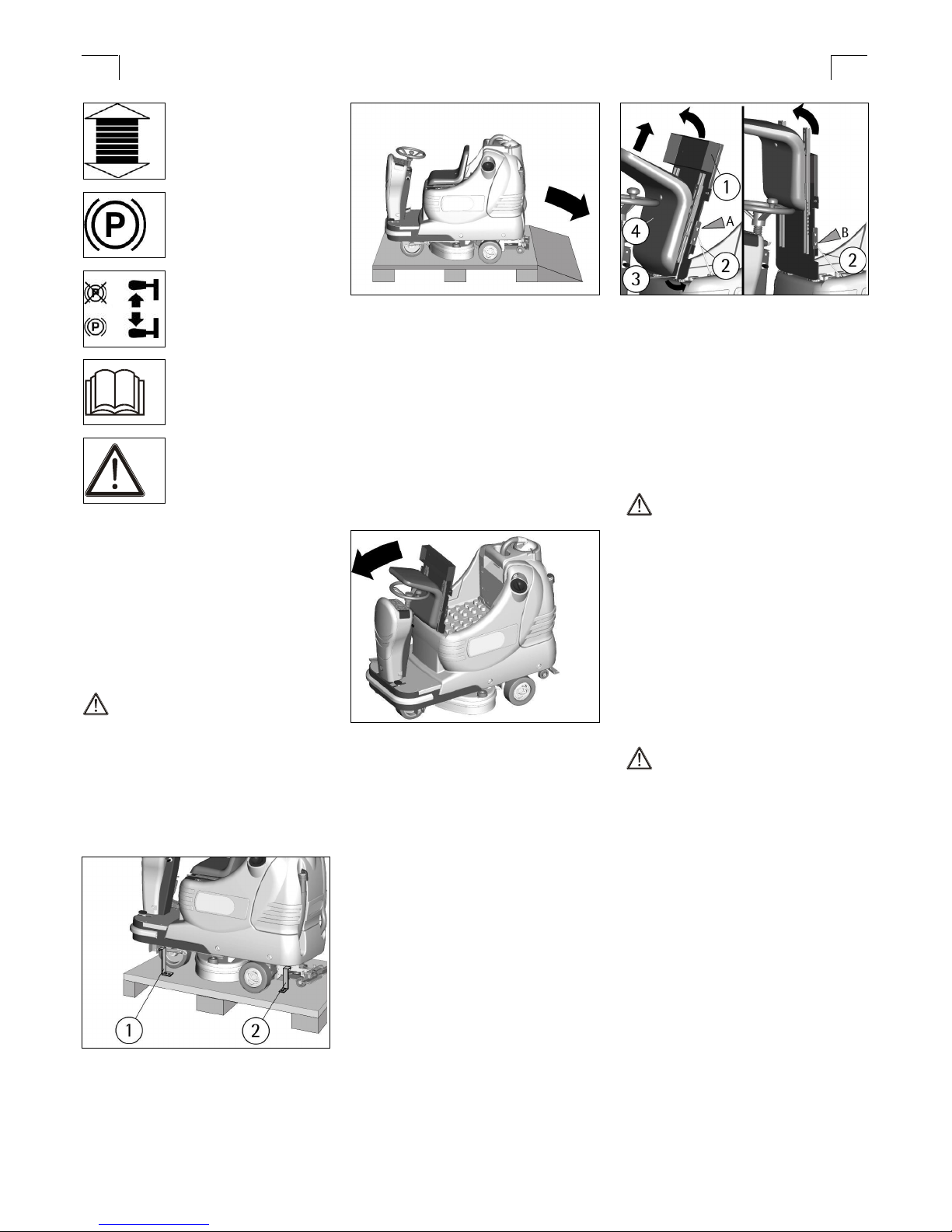
Indicates the direction of
operation:
forwards/backwards.
Indicates the brake. Light
indicates the brake is on.
Indicates the parking brake.
Indicates the operator has
to read the manual before
using the machine.
Warning symbol.
Read carefully the sections
marked with this symbol.
BEFORE USE
HANDLING PACKED MACHINE
The machine is supplied with suitable
packing for fork lift handling.
Total weight: 290kg.
Packing dimensions:
Base: 178 cm x 93 cm
Height: 138 cm
ATTENTION:
Do not place more than two
packages on top of each other.
UNPACKING THE MACHINE
1. Remove the external packing.
2. Unscrew the brackets (1and 2) that
secure the machine to the pallet.
4. Keep the pallet and the brackets for
future transport.
ACCESS TO THE BATTERY
COMPARTMENT
1. Ensure the machine is on a flat
surface.
2. Rotate the seat platform forward
and hook the bar.
When the operation is finished close
the battery compartment and
reposition the seat platform.
To install a battery into the
compartment, it is necessary to:
1. Rotate the seat platform forward
and hook the bar (2) into position A.
2. Remove the holder (1) by
unscrewing the two wing nuts under
the platform.
3. Pull the releasing lever of the seat
outwards (3) sliding the seat (4) up to
the highest position.
4. Rotate the platform further in order
to hook the bar (2) into position B.
This position will allow batteries to be
handled using suitable lifting
equipment.
BATTERY INSTALLATION
The machine is equipped batteries
connected in series for a total of 24
Volts, placed in its appropriate
compartment under the seat platform
and must be handled using suitable
lifting equipment (due to weight,
considering the type of batteries, and
coupling system).
ATTENTION:
The machine and the battery check
card indicates the use of traditional
lead batteries.
CHECK THE SETTING OF THE
CHECK CARD on the indicator (see
under paragraph "BATTERY
CHARGE LEVEL INDICATOR").
If using GEL batteries it is necessary
to MODIFY THE SETTING of the
electronic check card (see under
paragraph SETTING THE BATTERY
CHECK CARD”).
ATTENTION:
Strictly follow
manufacturer/distributor indications
for the maintenance and recharging of
batteries. All installation and
maintenance operations must be
carried out by authorized staff, using
suitable protection accessories.
To install the batteries it is necessary
to reach the battery compartment as
indicated under paragraph “ACCESS
TO THE BATTERY COMPARTMENT”.
1. Place the batteries in the
compartment.
2. Connect the terminals. Pay
attention to the polarities and avoid
contact with other parts that could
3. Move the machine backwards, as
indicated in the figure, avoiding heavy
contact to any mechanical parts.
short circuit.
BATTERY CHARGER
Be sure that the battery charger is
suitable for the batteries installed
(lead/acid or GEL or equivalent).
7
Page 7

BATTERY CHARGING
1. Plug the battery connector (3) of
the battery charger into the battery
connector (1).
2. Proceed with charging.
1. Disconnect the connector of the
battery charger from the battery
connector (1).
2. Reconnect the battery connector to
the machine connector (2).
3. The battery charge level indicator is
digital and remains fixed on the
display. The battery charge level
starts from 100, which indicates 100%
of the total charge and decreases in
10’s to 10. When the charge level
reaches 20%, the display starts
blinking.
ATTENTION:
Never charge a GEL battery with a
non suitable charger. Strictly follow
BATTERY CHARGE LEVEL
INDICATOR
To start any function of the machine, it
is necessary to rotate the key
clockwise (24). Rotating it counter
clockwise will switch the machine off.
the instructions supplied by the
battery and charger manufacturer.
In order not to cause permanent
damage to the battery, avoid
complete discharge. Charge the
battery within a few minutes after the
battery discharge signal starts blinking.
NOTE: Never leave the battery
completely discharged even when the
machine is not in use. In case of
traditional batteries, please check the
electrolyte level every 20 charging
cycles and top them up with distilled
water. Never leave the batteries
discharged for more than two weeks.
When the machine is switched on,
information will be displayed in the
following order (1):
1. the version (for example A003) of
software installed on the machine.
ATTENTION:
After a few seconds when the four
lines start blinking, all the functions
stop automatically. With the remaining
charge it is possible to finish the
drying operation before proceeding to
charge.
ATTENTION:
When charging the battery it is
important to follow all instructions
given by the manufacturer or
distributor. Installation and
maintenance operations must be
carried out by qualified staff. Danger
of gas exhalations and emission of
corrosive liquids. Fire danger: do not
approach with free flames.
BATTERIES DISPOSAL
It is mandatory to hand over
exhausted batteries, classified as
dangerous waste, to an authorized
institution according to the current
laws.
CONNECTING THE BATTERIES
CONNECTOR AND SWITCHING ON
THE MACHINE
Once the battery has been charged:
2. the setting of the battery check card
which can be:
GE 24 (check card set for GEL
batteries).
or
Pb 24 (check card set for lead
batteries).
SETTING THE BATTERY CHECK
CARD
The machine, if not specified
otherwise, is supplied with the battery
check card set for lead batteries. To
modify this setting, it is necessary to:
1. Switch the machine off then back
on.
2. Immediately after having switched
the machine back on, when the
writing Pb24 appears on the display
(1), press simultaneously the buttons
(3) and (6) until the writing begins to
flash.
3. When the writing begins to flash,
release the buttons and press the
button again once (6).
8
Page 8

4. The writing GE24 appears flashing.
5. When the writing stops flashing, the
setting is modified.
Both wheels must be adjusted to the
same height.
To change the setting from gel
batteries to lead batteries, repeat the
procedure pressing button (3) instead
of button (6).
SQUEEGEE ADJUSTMENT
In order to achieve good drying
HOUR METER
The machine is equipped with an hour
meter located on the same display (1)
as the battery charge level indicator.
Hold the button (13), the first data
indicates the working hours and after
a few seconds the working minutes
are shown.
results, the rear rubber of the
squeegee must be bent equally in
length. To adjust, it is necessary to
put the machine in operation and
therefore the vacuum motor has to be
switched on and the brushes have to
function together with the detergent
solution.
ATTENTION:
Every type of floor requires a
specific adjustment. For example,
concrete floors (where the friction
results will be high) need little
pressure, while smooth floors
(ceramics) need higher pressure.
If the cleaning operations are made
always on the same type of floor, the
adjustment can change only in
function of the rubber wear.
SPLASH GUARD ASSEMBLY
The two splash guards have to be
assembled onto the brushes base
group as indicated in the following
figures. Insert the metal strips inside
SQUEEGEE ASSEMBLY
1. Keep the squeegee support (1)
slightly lifted from the floor.
2. Insert the threaded parts of the two
bolts (4) sliding them inside the two
slots on the support placed on the
upper part of the squeegee (2).
3. Put the washers (3) into position,
there are two for each bolt, so that
they are assembled one under and
the other over each of the two slots
present on the support.
4. Secure the squeegee by rotating
the two levers (4) clockwise.
5. Insert the squeegee hose (5) into
its coupling, follow the picture for
positioning.
The lower part of the rubber is overly
bent
Take off the pressure by rotating the
wing nut (6) counterclockwise.
The lower part of the rubber is not
bent enough
Increase the pressure rotating the
wing nut (6) clockwise. Check that the
wheels that adjust the height are not
resting on the floor, in this case adjust
them as indicated in paragraph
"Height adjustment".
The bend is not equal
Adjust the squeegee inclination
rotating the wing nut counterclockwise
(7) to increase the bend in the central
part, or clockwise to increase the
the slots present on the rubber. Place
the round hole at the extremity of the
strip onto the screw (1) place in the
front part of the brushes base group.
Secure the strips through the nut
blocking it.
Secure the coupling lever (2) in the
rear part of the brushes base group to
the ring placed at the extremity of the
metal strip still free. Repeat as above
for both splash guard rubbers.
The splash guard must slightly touch
the floor when the brushes are
assembled.
To remove the splash guard follow the
above instructions in reverse.
bend on the outer part.
Height adjustment
Once the pressure and inclination of
the squeegee have been adjusted, it
is necessary to fix this optimum
condition ensuring the wheels only
slightly touch the floor. Rotate
counterclockwise the bolts (8) to lower
the wheels or clockwise to raise them.
9
Page 9

inclination of the bristles causes
excessive motor overload or
troublesome vibrations.
ASSEMBLING THE BRUSHES
To assemble the brushes it is
necessary that the brushes base is in
the lifted position. If it is not lifted,
proceed as follows:
Without the operator seated, turn the
key switch clockwise, the display
comes on and after 3 seconds all
working groups switch off
automatically and are lifted from the
floor.
Switch off the machine turning the key
counterclockwise.
ATTENTION:
Carrying out brush operations with
the electric supply on may cause
injury.
With the base of the brushes in the
lifted position, insert the brushes into
their plate seat underneath the
brushes base turning them until the
three metal buttons are properly
seated in their slots; rotate the
brushes to push the button towards
the coupling spring until they are
locked.
The figure shows the rotating direction
for brushes coupling.
For a longer life of the brushes we
suggest to daily alternate their
position. Whenever brushes do
become deformed we suggest to
reassemble them in the same position,
in order to avoid that the different
ATTENTION:
Use only brushes supplied with the
machine or ones indicated in the
paragraph “RECOMMENDED
BRUSHES”. The use of other brushes
can affect the cleaning result.
FLOOR CLEANING
RECOVERY TANK
Check that the cover of the vacuum
filter (1) is correctly secured, after
rotating the levers (2) and that the
vacuum motor hose (3) is correctly
connected to it.
Verify also that the squeegee hose
couplings (4/5) are correctly inserted
into their seats and that the drain
hose plug (6) placed in the rear part of
the machine is closed securely.
DETERGENT SOLUTION TANK
The solution tank capacity is indicated
in the technical data.
Open the screw cap placed in the left
part of the machine and fill the
solution tank with clean water at a
maximum temperature of 122º F
(50°C). Add the liquid detergent in
the percentage and conditions
recommended by the manufacturer.
To avoid excessive foaming, which
could cause problems to the vacuum
motor, use a minimum amount of
detergent. Screw down the cap to
close the tank.
ATTENTION:
Always use a low foaming detergent.
To avoid foaming, before starting the
machine, use a small amount of antifoaming product in the recovery tank.
Never use pure acid.
STARTING THE MACHINE
A safety device ensures that if the
operator is not seated correctly in the
seating position the machine does not
move.
To switch on the machine:
1. Sit on the seat.
2. Turn the key switch (24) clockwise
to switch on the machine.
Automatically, the machine gets ready
in manual (MAN) mode and in forward
movement with the quick speed
(signal lamp 22).
3. Check the charge level of the
batteries on the display (1).
4. Pressing the push button (5) the
functioning of BREAK WASHING is
chosen and the transfer operations of
the machine are carried out (see
under paragraph “FORWARD AND
BACKWARD MOVEMENT"). When
the signal lamp (4) is on the machine
is in BREAK WASHING mode.
5. Pressing the push button (6) the
automatic (AUTO) function is chosen,
when pressing the push button (3),
the function of the machine becomes
manual (MAN).
A. When the signal lamp (7) is on, the
machine is functioning in automatic
(AUTO) mode and the machine
activates and deactivates all the
working functions in an automatic
mode (see under paragraph
“WORKING IN AUTOMATIC MODE”).
B. When the signal lamp (2) is on, the
machine is functioning in manual
(MAN) mode and it is then possible to
choose:
I. to transport the machine without
activating or deactivating the working
functions.
10
Page 10

II. to separately activate only the
controls relative to the washing
function with the brushes (see under
paragraph “WORKING IN MANUAL
MODE”).
III. to separately activate only the
controls relative to the drying
that the fast drive is selected, while
signal lamp (23) indicates that the
slow drive is selected.
9. When moving in reverse, an
intermittent warning device is
activated.
function with the squeegee (see
under paragraph “WORKING IN
MANUAL MODE”).
ATTENTION:
In manual mode every function of
the machine has to be activated or
deactivated manually.
AUTOMATIC SQUEEGEE LIFTING
FORWARD AND BACKWARD
MOVEMENT
It is always recommended to move
and transport the machine in (BREAK
WASHING) mode
To activate the movement of the
machine proceed as follows:
1. Sit on the seat.
2. Turn the key switch (24) clockwise
to switch on the machine.
3. Check the charge level of the
batteries on the display (1).
4. Pressing the push button (5) the
functioning of BREAK WASHING is
chosen to carry out the transfer of the
machine. In fact, in this mode the
washing functions of the machine are
not working and only the traction
system functions. When the signal
lamp (4) is on, then the machine is in
BREAK WASHING mode.
5. Check through the signal lamp (15)
that the parking brake is not on and
release it if required (see under
paragraph EMERGENCY-PARKING
BRAKE”).
6. Positioning the selector (28)
forward, the forward drive is chosen,
while positioning it back, the rear drive
is selected.
7. Press the accelerator pedal placed
on the right of the platform to start the
machine.
8. Adjust the speed in forward drive
by pressing the push button (21) to
choose the slow one (maximum 3,6
km/h) or the fast one (maximum 5
km/h). The signal lamp (22) indicates
HORN
The machine is equipped with a horn
which is activated by pressing the
push button (1).
WORKING BRAKE
To stop the machine during normal
working conditions, it is sufficient to
release the accelerator pedal,
because the machine has an
electronic brake system. To restart,
press the accelerator pedal again.
EMERGENCY BRAKE
In case of an emergency, press the
brake pedal (1) placed on the lefthand side of the platform
To activate the parking brake press
the brake pedal (1) and
simultaneously move the lever
downward (2) situated on the left side
of the steering column.
On the instrument board the signal
lamp (15) comes on which signals
that the parking brake is on.
To release the parking brake press
the brake pedal (1).
WHEN GOING BACKWARDS
When reverse movement is selected
the squeegee is automatically raised
to the upper position. It will then lower
again once the forward movement
has been selected.
This happens both in automatic and in
manual mode in order to protect the
squeegee.
WORKING IN AUTOMATIC MODE
The automatic mode of operation is
useful to simplify the operator’s work.
1. Activate the machine (see under
paragraph “STARTING THE
MACHINE”).
2. Pressing the push button (6) the
automatic (AUTO) mode function is
selected. When the signal lamp (7) is
on, then the machine is functioning in
automatic (AUTO) mode.
3. Check that the knob of the solution
valve (27) is in the position of
optimum flow, depending on the type
of floor and the type of dirt (see under
the paragraph “FLOW ADJUSTMENT
OF THE DETERGENT SOLUTION”).
4. Position the selector (28) forward to
choose the forward drive.
5. Adjust the movement speed in
forward with the push button (21) (see
under paragraph "FORWARD AND
BACKWARD MOVEMENT").
6. By pressing the accelerator
pedal, the machine begins to move
forward and in automatic mode
pressing the accelerator pedal
activates all the working functions.
Automatically the squeegee goes
down, the brushes begin to turn, the
11
Page 11

solenoid valve opens to permit the
detergent solution to flow down onto
the brushes and the vacuum system
is activated to recover the dirty water
from the floor.
By positioning the selector (28)
backwards the reverse drive is
selected and by pressing the
accelerator pedal the reverse drive
starts, the squeegee lifts automatically
and will then return to lower itself
during the next forward movement.
If the accelerator pedal is released
for more than 3 seconds, all the
functions are automatically
switched off and both the brushes
stop and the squeegee is lifted.
Pressing the pedal again, the
machine starts to move and in
automatic mode all the working
functions are reactivated.
TO CARRY OUT THE WASHING
WITH ONLY THE BRUSHES:
1. Check that the knob of the solution
valve (27) is in the position of
optimum flow, depending on the type
of floor and the type of dirt (see under
the paragraph “FLOW ADJUSTMENT
OF THE DETERGENT SOLUTION”).
2. Press the push button (17) to lower
the brushes. Once lowered, the
brushes begin to turn. The signal
lamp (16) indicates that the brushes
base is lowering or lifting, while the
signal lamp (18) signals that the
brushes are turning.
3. Press the switch (19) to open the
solenoid valve and permit the
detergent solution to flow down onto
the brushes. The signal lamp (20) will
come on, to indicate that the solenoid
valve is open.
WORKING ADJUSTMENTS
In automatic mode as in manual mode,
during the first metres check:
1. That the squeegee adjustment
guarantees a perfect drying result
(see under paragraph “SQUEEGEE
ADJUSTMENT”).
2. That the adjustment of the
detergent solution flow is sufficient to
wet the floor evenly avoiding the
leakage of detergent from the splash
guards (see under paragraph “FLOW
ADJUSTMENT OF THE
DETERGENT SOLUTION”).
3. That the pressure of the brushes
permit an efficient washing action in
relation to the dirt and the speed (see
under paragraph “ADJUSTMENT OF
THE BRUSHES PRESSURE”).
FLOW ADJUSTMENT OF THE
DETERGENT SOLUTION
To adjust the detergent solution
quantity that flows down onto the
brushes it is necessary to adjust the
solution valve knob (27) placed on the
right of the steering column, rotate the
knob counterclockwise to increase the
flow and clockwise to reduce it up to
shutting off the flow of solution.
BRUSH PRESSURE ADJUSTMENT
Using the knob (10) it is possible to
adjust the brush pressure onto the
floor in three pre-set pressure levels.
The display (1) will indicate the
pressure in kg that has been
previously set by pressing the push
button (14).
Adjustment is possible in both
automatic and manual mode.
WORKING IN MANUAL MODE
The manual model is useful when, in
specific cases, it is necessary to carry
out only the washing with the brushes
or only the drying of the floor.
ATTENTION:
The washing and drying functions,
when they are not carried out
simultaneously, represent an
improper use of the machine (see
under paragraph “GENERAL
RULES OF SECURITY”). If they are
carried out separately, it is
necessary to prohibit un-authorized
personnel from the cleaning areas
and to signal areas of wet floors
with suitable signs.
1. Activate the machine (see under
paragraph “STARTING THE
MACHINE”).
2. Press the push button (3), manual
(MAN) mode is chosen. When the
signal lamp (2) is on, the machine is
functioning in manual (MAN) mode.
TO CARRY OUT THE FUNCTION OF
ONLY DRYING:
1. Press the raise/lower squeegee
button (11) to lower the squeegee.
The signal lamp (12) indicates that the
squeegee is lowering or lifting.
2. Press the vacuum motor switch (9)
to start the vacuum system. The
signal lamp (8) indicates that the
machine is drying.
Position the selector (28) forward to
choose the forward drive.
Adjust the movement speed in
forward with the push button (21) (see
under paragraph "FORWARD AND
BACKWARD MOVEMENT”).
Pressing the accelerator pedal, the
machine begins to proceed forward
and to work according to the set
functions.
ATTENTION:
In manual mode every function of
the machine has to be activated or
deactivated manually.
12
Page 12

ATTENTION:
In order not to overload the brush
motor, reduce the brush pressure
functions have to be re-established
manually.
going from smooth floors to rough
ones (ex. concrete).
STOPPING THE MACHINE AFTER
ELECTRIC PROTECTION
The machine is equipped with an
electronic system of protection for all
components that carry out functions of
power or control. This device blocks
the defective component and
indicates on the display (1) the
corresponding alarm from ”AL01” to
“AL20”.
ATTENTION:
To restore the functioning of the
component, turn the machine off and
back on using the key switch. If the
problem persists, please contact an
authorized technical person.
OVERFLOW DEVICE
To avoid serious damage to the
vacuum motor, the machine is
equipped with a mechanical float that
intervenes when the recovery tank is
full which closes the vacuum hose
and stops the vacuum.
CLEANING
IN AUTOMATIC OR MANUAL
WORKING MODE:
1. At the end of the washing cycle,
pressing the push button (5), the
function of BREAK WASHING is
chosen. When the signal lamp (4) is
on, then the machine is in BREAK
WASHING mode. In this way the
brushes lift automatically, the solenoid
valve shuts down and it is possible to
finish the drying operation.
2. When the accelerator pedal is
released for more than 3 seconds, the
squeegee raises itself and the
vacuum switches off automatically.
3. After three seconds, the accelerator
can be pressed again, if a machine's
transfer has to be made (the transfer
can be carried out also if the pedal is
never lifted, in this case the squeegee
gets lifted and the vacuum stops
automatically after 15 seconds).
4. Turn the switch key
counterclockwise to switch off the
machine.
5. Insert the parking brake (see under
paragraph “EMERGENCY-PARKING
BRAKE”).
ATTENTION:
The mode (BREAK WASHING)
is specific for the transfer at the end of
the cleaning operation.
DAILY MAINTENANCE
ATTENTION:
The following maintenance and
cleaning operations refer to those
components that are in contact
with liquids:
· Solution and recovery tanks
· Solution and recovery filters
· Squeegee including squeegees
and hoses
· Brushes
The following operations must be
carried out using gloves to protect
from dangerous solutions.
EMPTYING AND CLEANING THE
RECOVERY TANK
1. Hold the drain hose (1) placed in
the rear part of the machine after
having taken it off from its fixed
position.
2. Take the plug off (2) the drain hose
by pulling the lever (3) and empty the
recovery tank into appropriate
containers, in compliance with the
respective rules of liquid disposal
regulations.
3. Take off the vacuum cover (4) after
rotating the blocking levers (5).
4. Take off the filter and the filter
protection (6).
5. Rinse the inside of the tank with a
water jet.
6. Reassemble all parts.
When this happens, empty the
recovery tank (see under paragraph
“RECOVERY TANK EMPTYING AND
CLEANING”).
To start the cleaning operation again:
A. to start working in automatic mode
(AUTO) press push button (6).
B. to start working in manual mode
(MAN) press push button (3). All
13
Page 13

3. Turn the rubber to a new side or
replace it.
To reassemble the squeegee repeat
inversely the operations mentioned
above, inserting the rubber on the
guides and blocking it with the rubber
holder blade.
CLEANING THE VACUUM FILTER
1. Take off the vacuum cover (4) after
rotating the blocking levers (5).
2. Take off the filter (8) and its filter
protection (6).
3. Clean all parts with a water jet and
especially the inside surfaces and the
filter bottom.
4. Carry out cleaning operations
carefully.
5. Reassemble all parts.
CLEANING THE BRUSHES
Disassemble the brushes and clean
them with a water jet (for dissembling
the brushes see under paragraph
“DISASSEMBLING THE BRUSHES”).
DISASSEMBLING THE BRUSHES
With the brushes base in the lifted
position (see under paragraph
"BRUSH ASSEMBLY"), rotate the
brushes in order to release the button
from the coupling spring until it
becomes free and wash them with a
water jet. The figure shows the
rotating direction to release the
brushes.
ATTENTION:
Disassembling the brushes with the
electric supply on may cause injury.
CLEANING THE SQUEEGEE
Keeping the squeegee clean
guarantees the best drying result.
To clean the squeegee it is necessary
to:
1. Take off the squeegee hose (5)
from the coupling.
2. Disassemble the squeegee (2) from
its support (1) by loosening the knobs
(4) counterclockwise and sliding the
threaded parts in the appropriate slots
up to their release.
3. Clean with care the internal part of
the squeegee inlet eliminating any dirt.
4. Clean with care the squeegee
rubbers.
5. Reassemble all parts paying
attention to put the washers (3) into
position, there are two for each knob,
so that they are assembled one under
and the other on each of the two slots
present on the support.
WEEKLY MAINTENANCE
REAR SQUEEGEE RUBBER
CHECK
Check the squeegee rubber wear and
eventually turn or replace it.
For the replacement it is necessary to:
1. Lift the squeegee (see under
paragraph “STOP OF THE MACHINE
AFTER CLEANING OPERATION”).
2. Release the hook (1) of the rubber
holder blade and take off the rubber.
SQUEEGEE HOSE CLEANING
Weekly or in case of insufficient
vacuum, it is necessary to check that
the squeegee hose is not blocked. To
clean it, proceed as follows:
1. Take off the hose (1) from the
squeegee coupling.
2. Wash the inside of the hose with a
water jet.
3. To reassemble the hose repeat in
reverse the above-mentioned
operations.
CLEANING THE SOLUTION TANK
AND THE OUTER FILTER
1. Bring the machine to an
appropriate area to drain the solution
tank.
2. Unscrew the solution tank cap (1).
3. Unscrew the cap of the exhaust
filter (2) and take off the filter. Be
careful not to lose the cap’s gasket.
4. Open the solution valve (see under
paragraph “FLOW ADJUSTMENT OF
THE DETERGENT SOLUTION”), so
that the detergent solution flows down
into appropriate containers.
5. Rinse the solution tank and filter
components with a water jet.
14
Page 14

6. Reassemble all parts.
NOTE: if required it is possible to
wash only the components of the
Pour some water into the tank to
clean it. Reassemble the fitting onto
the solution tank.
outer solution filter by closing the
solution valve adjustment (see under
paragraph “FLOW ADJUSTMENT OF
THE DETERGENT SOLUTION”), so
that the detergent solution remains in
the solution tank.
CHECKING THE BRAKES
Check the brake of both rear wheels.
Should the braking be insufficient,
please contact an authorized
technical assistance.
TWO-MONTHLY MAINTENANCE
FRONT SQUEEGEE RUBBER
CHECK
Check the wear of the squeegee
blade and replace when necessary.
For replacement:
1. Take off the squeegee (see under
paragraph “CLEANING THE
SQUEEGEE”).
2. Unscrew the wing nuts in the front
part of the squeegee.
3.Take off the squeegee holder blade.
4. Replace the front blade.
5. Reassemble all parts.
SIX-MONTHLY MAINTENANCE
SPLASH GUARD RUBBER CHECK
With the brushes assembled, the
splash guards must touch the floor
slightly. If they are worn, they have to
be replaced. Just release the springs
placed in the rear part of the brushes
base group from the slots placed at
the free extremities of the metal strips
to take off the rubbers and to reinsert
the new ones (see under paragraph
“SPLASH GUARD ASSEMBLY”).
CLEANING THE INNER FILTER OF
THE SOLUTION TANK
Empty the solution tank, remove the
fitting (1) of the water outlet by taking
off the two screws that fix it to the tank
in the rear part of the machine. Clean
the inside filtration part of the fitting.
TROUBLESHOOTING GUIDE
ATTENTION:
If when the key switch is positioned
clockwise when switching the
machine on and the display and other
functions are not activated, it is
necessary to check the batteries'
connection to the machine (see under
paragraph “CONNECTION
BATTERIES' CONNECTION AND
STARTING THE MACHINE”). If the
problem persists, please contact the
authorized technical assistance.
THE VACUUM MOTOR DOES NOT
WORK
1. Verify that the key switch is
positioned clockwise to switch on the
machine. If the alarm signals it is
necessary to switch the machine off
and on again to restore the
functionality.
2. Check the charge level of the
batteries on the display (1).
3. Verify that the drying function is
correctly activated. (see under
paragraph “STARTING THE
MACHINE”).
4. Check that the recovery tank is not
full.
5. If, both in mode (MAN) and
(AUTO),the signal lamp (8) is on
but the vacuum system does not
work, please contact the
authorized technical assistance.
THE BRUSH MOTOR DOES NOT
WORK
1. Verify that the key switch is
positioned clockwise to switch on the
machine. If the alarm signals it is
necessary to switch the machine off
and on again to restore the
functionality.
2. Check the charge level of the
batteries on the display (1).
3. Verify that the function of washing
with the brushes has been correctly
selected (see under paragraph
“STARTING THE MACHINE”).
4.If, both in mode (MAN) and (AUTO),
the signal lamp (18) is on but the
brushes do not turn, please contact
an authorized technical centre.
THE TRACTION MOTOR DOES NOT
WORK
1. Sit on the seat.
2. Verify that the key switch is
positioned clockwise to switch on the
machine. If the alarm signals it is
necessary to switch the machine off
and on again to restore the
functionality.
3. Check the charge level of the
batteries on the display (1).
15
Page 15

4. Check that the parking brake signal
lamp (15) is not on and release it if
necessary (see under paragraph
“EMERGENCY-PARKING BRAKE”).
5. Press the accelerator pedal placed
on the right side to start the machine.
If the problem persists, please contact
the authorized technical assistance.
THE WATER DOES NOT COME
DOWN ONTO THE BRUSHES OR IS
INSUFFICIENT
1. Verify that the key switch is
positioned clockwise to switch on the
machine.
2. Check the charge level of the
batteries on the display (1).
3. Verify that the function of washing
with the brushes is correctly activated
(see under paragraph “STARTING
THE MACHINE”).
4. Check that the solution valve is
open (see under paragraph “FLOW
ADJUSTMENT OF THE
DETERGENT SOLUTION”).
5. If, both in (MAN) and (AUTO),
mode the signal lamp (20) is on but
the detergent solution does not come
down onto the brushes, it is
necessary to:
a. check the level of the liquid in
the tank.
b. check that the solution filter is
clean (see under paragraph
“CLEANING THE SOLUTION
TANK AND THE OUTER
FILTER”).
c. check that the inner filter of
the solution tank is clean (see
under paragraph “CLEANING
THE INNER FILTER OF THE
SOLUTION TANK”).
If the problem persists, please contact
the authorized technical assistance.
THE MACHINE DOES NOT CLEAN
PROPERLY
1. The brushes do not have the
suitable bristle dimension: contact an
authorized technical centre.
2. The brushes have worn out bristles.
Check the brush wear condition and
replace if necessary (the brushes
have to be replaced when the bristles
have reached a height of about ½”
15mm).
To replace the brushes, see
instructions under paragraph
“DISASSEMBLING THE BRUSHES”
and “ASSEMBLING THE BRUSHES”.
3. The detergent solution is
insufficient: open the solution valve
more (see under paragraph “FLOW
ADJUSTMENT OF THE
DETERGENT SOLUTION”).
4. Check that the liquid detergent is in
the recommended percentage.
5. Increase the brush base pressure
(see under paragraph " BRUSHES
PRESSURE ADJUSTMENT ").
Contact an authorized technical
centre for advice.
THE SQUEEGEE DOES NOT DRY
SUFFICIENTLY
1. Check that the vacuum function is
on and that the recovery tank is not
full.
2. Check that the squeegee blades
are clean (see under paragraph
“CLEANING THE SQUEEGEE”).
3. Check the adjustment of the height
and the inclination of the squeegee
(see under paragraph “SQUEEGEE
ADJUSTMENT”).
4. Check that the vacuum and the
squeegee hoses are correctly inserted
in their proper seats on the recovery
tank.
5. Clean the vacuum filter (see under
paragraph “CLEANING THE
VACUUM MOTOR”).
6. Clean the squeegee hose (see
under paragraph “SQUEEGEE HOSE
CLEANING”).
7. Replace the blades if worn out.
EXCESSIVE FOAM PRODUCTION
Check that low foam detergent has
been used. Add small quantities of
anti foam liquid into the recovery tank.
Please be aware that more foam is
produced the cleaner the floor. In this
case please dilute detergent solution.
16
Page 16

PROGRAMMED MAINTENANCE
IINTERVAL DAILY 20 HOURS * 200 HOURS *
RECOVERY TANK CLEANING
VACUUM FILTER CLEANING
·
·
SOLUTION TANK FILTER CLEANING
BRUSH CLEANING
BRUSH DISASSEMBLY AND CLEANING
SQUEEGEE CLEANING
·
·
·
FRONT SQUEEGEE BLADE REPLACEMENT
REAR SQUEEGEE BLADE REPLACEMENT
·
·
·
SPLASH GUARD RUBBER REPLACEMENT
CHECK SQUEEGEE ADJUSTMENT
SQUEEGEE HOSE CLEANING
SOLUTION TANK CLEANING
CHECK BATTERY ELECTROLYTE
·
·
·
·
CHECK THE BRAKE
CHECK THE TRACTION MOTOR
CHECK THE BRUSH MOTOR
CHECK THE VACUUM MOTOR
CHECK THE BRUSH BASE
·
SCREW TIGHTENING
1000 HOURS
*
·
·
·
·
·
·
* The hours refer to the ones indicated on the display (see under paragraph ”HOUR METER”).
RECOMMENDED BRUSHES
Brushes must be chosen depending on floor type and dirt to be removed.
The material and bristle diameter are the elements that distinguish different types of brushes.
MATERIAL CHARACTERISTICS
PPL (Polypropylene) Good wear resistance. Maintains characteristics with hot water up to 50°C. It is not hygroscopic.
NYLON Excellent wear resistance, even with hot water. It is hygroscopic.
TYNEX
BRISTLES
THICKNESS
PAD HOLDER
Nylon bristles with grains of abrasive material. Use with caution in order not to mark the floor or
ruin the polishing.
Thicker bristles are more rigid and must be used on smooth floor or floor with small joints. On
irregular floors with deep joints or relieves, it is recommended to use softer bristles which
penetrate more easily and deeper. Please be aware that when brush bristles are worn out and
therefore too small, they become rigid and unable to penetrate and clean deeper. This may also
happen with thicker bristles creating brush vibration.
It has anchor points which permit the blocking of the abrasive pad during work. The pad is
recommended to clean smooth floors.
MACHINE CODE QUANTITY DESCRIPTION USE
BD26/22 48903020 2 Brush PPL 0,6 Ø 345 Normal floors.
Smooth floors with small joints and
48903030 2 Brush PPL 0,9 Ø 345
persistent dirt.
48903040 2 Brush TYNEX Ø 345 Floors of resistant material and particularly
48803030 2
Pad holder Ø 330 + center lock
green
dirty.
For pads of 14”, for smooth surfaces
cleaning.
17
 Loading...