

Page 1

Tornado
Operation and Illustrated Parts Manual
For Commercial Use Only
TORNADO® INDUSTRIES
7401 W. LAWRENCE AVENUE
CHICAGO, IL 60706
(708) 867-5100 FAX (708) 867-6968
www.tornadovac.com
Long-Range Floorkeeper Automatic Scrubber
Form No. L9332AA 2/01 ã2001 Tornadoâ Industries All rights reserved.
Catalog No.
99328 & 99332
Page 2

NOTES
2
Page 3

This illustrated parts book covers:
MODEL 99328 99332
SIZE 28" 32”
VOLTS (CHARGER) 36V 36V
AMPS 20 20
CAPACITY 20 GAL. (79l) 20 GAL (79l)
SERIES A A
All specifications are subject to change without notice.
Tornado® Standard Warranty Program*
10 Years:
All plastic tanks and rotationally-molded bodies
Warranties do not cover
components subject to
normal wear or abuse and
misuse, and have other
limitations not specified
here. For full details ,
contact your Authorized
Tornado Distributor,
Service Center, or the
Tornado Technical Service
Department.
Parts on all Tornado and Tornado/Karcher cleaning
Labor on all Tornado and Tornado/Karcher cleaning
2 Years:
equipment
1 Year:
equipment
1) 2)
1) 2)
1 Year:
Warranty on batteries, one full year, not pro-rated.
* Effective January 1st, 2001. Terms subject to change without notice.
1) Windshear™ Blower-Dryer, Insulation Blowers, CW 50, CW 100, and Duo-Upright Carpetkeepers™ are
warranted for 1 (one) year for parts and labor.
2) Warranties on the ICC1, KMR 1200, KMR 1250, and KMR 1700 are 24 months parts/6 months labor OR 1000
hours of operation, whichever comes first. Warranties on the BR and BD 1000 are 24 months parts/12 months
labor OR 1000 hours of operation, whichever comes first.
3
Page 4

TABLE OF CONTENTS
INTRODUCTION 5
UNIT CONTROLS AND INDICATORS 6
INSTALLATION
BATTERY 8
SQUEEGEE 9
RECOVERY TANK DRAIN 10
BRUSHES 10
PRE START-UP
FILLING SOLUTION TANK 11
PREVENTATIVE MAINTENANCE PROGRAM
INTRODUCTION 12
BATTERY CARE 12
BATTERY CHARGING 14
SQUEEGEE BLADES 15
SQUEEGEE ADJUSTMENT 16
VACUUM AND WATER RECOVERY SYSTEM 17
SOLUTION AND RECOVERY (Vacuum) TANKS 17
VACUUM MOTOR 18
WHEELS 18
LUBRICATING YOUR MACHINE 19
MOTOR BRUSH REPLACEMENT 19
TROUBLESHOOTING INSTRUCTIONS
VACUUM SYSTEM (POOR SUCTION) 20
POOR SOLUTION FLOW 21
ELECTRICAL PROBLEMS 22
BATTERIES NOT HOLDING CHARGE 22
TROUBLESHOOTING SYMPTOMS CHART 23
LCD DISPLAY DIAGNOSTIC ERROR CODES 24
PREVENTATIVE MAINTENANCE CHECKLIST 25
ILLUSTRATED PARTS LISTS
28” SQUEEGEE - EXPLODED VIEW & PARTS LIST 26
32” SQUEEGEE - EXPLODED VIEW & PARTS LIST 27
SQUEEGEE PIVOT FRAME ASSEMBLY - EXPLODED VIEW 28
SQUEEGEE PIVOT FRAME ASSEMBLY - PARTS LIST 29
SOLUTION CONTROL ASSEMBLY - EXPLODED VIEW & PARTS LIST 30
DRAIN & SOLUTION VALVES - EXPLODED VIEW & PARTS LIST 31
28” BRUSH MOTOR ASSEMBLY - EXPLODED VIEW 32
28” BRUSH MOTOR ASSEMBLY - PARTS LIST 33
32” BRUSH MOTOR ASSEMBLY - EXPLODED VIEW 34
32” BRUSH MOTOR ASSEMBLY - PARTS LIST 35
RECOVERY (VACUUM) TANK ASSEMBLY - PARTS LIST 36
RECOVERY (VACUUM) TANK ASSEMBLY – EXPLODED VIEW 1 37
RECOVERY (VACUUM) TANK ASSEMBLY – EXPLODED VIEW 2 38
SOLUTION TANK ASSEMBLY - EXPLODED VIEW & PARTS LIST 39
BATTERY ASSEMBLY - EXPLODED VIEW & PARTS LIST 40
CONTROL PANEL ASSEMBLY - EXPLODED VIEW & PARTS LIST 41
TRIGGER ASSEMBLY - EXPLODED VIEW & PARTS LIST 42
MAIN VIEW “A” – MAJOR SUBASSEMBLIES EXPLODED VIEW 43
MAIN VIEW “B” – EXPLODED VIEW 44
MAIN VIEW “B” – PARTS LIST 45
MAIN VIEW “C” – EXPLODED VIEW 46
MAIN VIEW “C” – PARTS LIST 47
COVER ASSEMBLY - EXPLODED VIEW & PARTS LIST 48
WIRING DIAGRAM 49
WIRING HARNESS CONTROL FUNCTIONS 50
WIRING HARNESS POWER FUNCTIONS 51
4
Page 5

INTRODUCTION
Congratulations on the purchase of your new
Tornado Floorkeeper! The Floorkeeper
combines many advanced features to maximize
reliability, performance, and ease of use. The
most notable addition is the incorporation of the
industry’s first fully functional digital control and
display system on an automatic floor scrubber.
With it, you’ll be able to easily and accurately
monitor an assortment of system settings and
conditions. Tornado’s new digital controller has
a unique soft-start feature that increases both
efficiency and powertrain lifespan.
This new Floorkeeper’s simplified wiring
harness uses quick-disconnects, and combined
with the digital controller, it makes servicing and
troubleshooting easy. A tough new rotomolded
housing extends over an advanced one-piece
steel weldment, making this new Long-Range
both more rugged and much lighter than
previous Long-Range models.
Additional features include removable 20-gallon solution and vacuum tanks, a reliable 18:1 gear
ratio transaxle, non-marking 11” tires, easy-access batteries, and error code generation on its
LCD display. The new Long-Range Floorkeeper automatic scrubber was designed and built to
exceed your needs for durability and serviceability in demanding commercial environments.
This manual is designed to instruct your personnel in the operation, maintenance and methods
of troubleshooting on your Tornado Floorkeeper. Please read through this manual and keep it
handy to ensure that you get maximum satisfaction and value from this new advance in floor
care.
OBSERVE THESE PRECAUTIONS
FOR SAFE USE OF THIS MACHINE
TO AVOID DANGER:
• Back the machine down inclines or ramps. Do not store machine on inclines.
• Make certain that the power switch is OFF before removing or installing brushes.
• Use care when working on electrical terminals —short circuits can cause burns and throw sparks.
• Disconnect both positive and negative battery terminals before attempting any adjustment or main-
tenance. Brush or traction drive motors and drive components could cause injury if started while
being worked on.
• Charge batteries in a ventilated room where gases cannot accumulate. Gases given off during
charging could ignite in a confined space. Make certain that the top covers are open when
charging so gases cannot accumulate.
• Battery acid can cause injury to the eyes or burn the skin.
5
Page 6

Unit Controls and Indicators
Control Panel
1. Vacuum Motor
Switch
2. Variable Speed
Control Knob
3. LCD Display
4. Display Mode
Button
5. Brush Pressure Switch
Rear Controls
6. Adjustable
Solution
Control
7. Dual Drive
Levers
8. Dual Reverse
Buttons
9. Emergency
Stop Switch
10. Key Lock
11. Circuit Breaker
12. Squeegee Control Lever
13. Recovery Tank Drain Hose
6
Page 7

Unit Controls and Indicators
Display Screens
Use the Display Mode Button (to the right of the display) to toggle between three unique
screens. Each screen displays a different set of icons and numerical readouts to give you useful
information about your Long-Range’s operating status. For particulars on diagnostic fault code
information, see page 24.
7
Page 8

INSTALLATION
Batteries
Raise top cover using handle, and pivot forward until
retainer cords are taut.
CAUTION
Batteries are heavy. To avoid injury, use two people
to lift into position.
Place batteries in metal tray liner. Orient each battery
exactly as shown in bottom photo, or refer to chart
located under the hood. Ensure that positive and
negative terminals are positioned and connected
correctly.
CAUTION
Observe polarity.
Place battery terminal protectors over posts.
WARNING
Battery acid can cause severe burns. Make sure
battery caps are tight to avoid spills or splashing of
acid.
Close cover.
8
Page 9

INSTALLATION
Squeegee
1. Make sure squeegee adjustment
lever is locked in UP position.
Install two adjustment knob
assemblies on squeegee
assembly. Do not thread in all
the way.
2. Slide squeegee assembly on
pivot frame and tighten
adjustment knobs.
3. Insert hose end into squeegee
assembly nozzle throat. Press
down tightly.
Squeegee can be locked in UP position by
raising lever and moving it to the left.
Squeegee can be locked in DOWN position
by pushing lever down and moving it to left.
NOTE: For even floors, squeegee can be set
to float by setting lever halfway between UP
and DOWN positions. Lock in DOWN position
for uneven floors.
NOTE: Never store machine with squeegee
in down position.
NOTE: Always raise squeegee while
backing up.
9
Page 10

INSTALLATION
Recovery Tank Drain
Install drain door on mounting hardware. Make sure thumb screws
are tight. Place top of hose on hose bracket.
Brushes
1. Raise brush heads using switch on control panel.
2. Place brushes or pad holders under cover. Locate
brush coupler. Pull up to lock in place.
3. Check to see that two solution feed hoses are
connected to fittings on top of brush cover.
10
Page 11

PRE START-UP
Turn key and power switch on and lower brushes to
test. Brush motors will automatically turn on when
brushes are lowered.
Filling Solution Tank
1. Raise top cover.
2. Always empty recovery tank before filling solution
tank. This will eliminate overfilling of recovery
tank.
Lift solution tank cover and fill.
3. Close top covers by pushing covers down.
You are now ready to operate your machine.
Follow maintenance schedule on page 23 to ensure proper operation of your machine.
11
Page 12

TORNADO FLOORKEEPER
PREVENTIVE MAINTENANCE PROGRAM
Introduction
This section is designed to instruct your personnel in methods of maintenance on the Tornado
Floorkeeper. By following these procedures, repair costs and down time will be greatly reduced.
These procedures are for simple repairs that can easily be done by your own personnel.
WARNING
Battery acid is toxic and corrosive; avoid bodily
contact.
First Aid:
EYES: Wash with liberal quantities of running
water for 15 minutes.
SKIN: Flush area with plentiful amounts of
running water.
INGESTION: Give milk to drink, DO NOT induce
vomiting, call a physician.
SPILLS: Wash with water or neutralize with
sodium carbonate or bicarbonate
(baking soda).
Battery Care
Batteries must be checked daily. The water level
must be maintained at least 1/4” above top of cell
plates in each battery.
1. Raise top covers and lock in place.
2. Remove battery caps and fill.
NOTE: Fill batteries with distilled water only. This
will increase battery life substantially.
12
Page 13

MAINTENANCE
CAUTION
Do not overfill the battery cells. Do not use a hose
or pail. If batteries are accidentally overfilled,
remove excess water with the hydrometer provided
with the machine. Dispose of excess in accordance
with local, state and federal regulations.
3. After filling batteries, replace the battery
caps. Using baking soda or ammonia and
water solution, saturate a cloth and wring until
drip dry. Use this cloth to wipe the battery tops.
4. The battery terminals and connections need
to be coated with a protective lubricant to
prevent corrosion.
WARNING
Avoid accidental contact with battery terminals and
possible electrical shock. Replace protective
plastic terminal covers after battery maintenance.
13
Page 14

MAINTENANCE
Battery Charging
The charger is fully automatic:
1. It turns on when plugged in.
2. It switches to equalizing charge.
3. It shuts off when it reaches full charge or when batteries are defective.
NOTE: It is recommended that new batteries be fully discharged at least once (more in some cases) to enable
batteries to hold a full charge.
The batteries must be charged after each use of 3 or more hours. Failure to do so will result in shortened running
time.
To charge the batteries, raise top covers and lock in position.
WARNING
To avoid explosion keep covers open during charge to insure proper ventilation of gases.
1. Connect charger cable by plugging it into Andersenä
connector located under rear top cover.
2. Plug AC cord into proper electrical receptacle. The red
“CHARGER ON” light will automatically come on along
with the “INCOMPLETE” light, meaning batteries are being
charged.
3. The charger will automatically turn off when the
batteries are charged to their maximum capacity. The
“CHARGER ON” light will go out when the charge cycle is
complete.
4. To stop the charge cycle push the “INTERRUPT”
button. (Do not unplug A.C. cord while the charger is on.)
5. Check the lights on the battery charger after charger
shuts off (“CHARGER ON” light should not be lit):
A.Green light: Batteries are fully charged and are in good
condition.
B.Amber light: All cells are OK but the total battery capacity is
reduced. This usually indicates that the batteries are aging.
C.Red light: The battery capacity is low and the entire
charger/battery system needs to be inspected by a qualified
Tornado serviceman.
14
Page 15

MAINTENANCE
Squeegee Blades
1. If a squeegee blade is worn or ripped, raise the squeegee
assembly and remove the entire squeegee assembly.
Disconnect vacuum hose, loosen two thumb screws and
slide pivot frame out. Remove the wing nuts on the rear of
the squeegee housing. Then remove the metal support
strap.
2. Squeegee blades can be repositioned to provide a new edge. See Figure 1
The front blade has two working edges (ref. #1, 2).
Flip blade for new edge when worn.
The rear blade has four working edges (see ref. #3 through 6).
When edge is worn, turn blade so new edge is on bottom,
facing front of squeegee.
NOTE: Edges of front and rear blades must be parallel to
each other.
3. Place the metal support strap back into position. Replace
the wing nuts on rear of the squeegee housing. Do not overtighten wing nuts as this will wrinkle the squeegee blade and
cause streaking during recovery.
Always keep the squeegee blade edge straight for best
results.
Clean squeegee blades with a damp cloth.
15
Page 16

MAINTENANCE
Squeegee Adjustment
1. Height and flatness adjustments are made by
loosening the four screws (A & B) and lifting or lowering
the entire squeegee mechanism as desired.
2. Turn machine on and move machine forward slightly.
3. Look down at the contact being made between the
squeegee blades and the floor. Make adjustments
as required.
4. Correct adjustment is made when squeegee blades rest
evenly on the floor. Tighten four screws (A & B).
Blade pressure is adjusted by lengthening or shortening
the length of the squeegee link.
There are three holes at each end of link which are used
for adjustments.
For Smooth Floors:
Use the soft (3/1 6”) rear squeegee blade. (Standard)
Release the squeegee lever above and allow the
squeegee to rest on the floor.
For Rough Floors:
Use the firm (1/4” thick) rear squeegee blade.
Lock the handle in the down position so that squeegee is
forced down to floor.
16
Page 17

MAINTENANCE
Vacuum and Water Recovery System
NOTE: A dirty or clogged filter will greatly reduce
suction and ability of machine to recover water.
Inspect vacuum filter after each use as follows:
1. Disconnect hose.
2. Turn the two cam-shaped thumb locks.
3. Remove filler assembly.
4. Remove foam filter and rinse with clean water.
5. Drain and flush tanks with clean water.
6. Leave filter assembly out of tank to allow
system to dry when not in use.
A liquid shutoff is built into the filter system to prevent overfilling
tank.
Solution and Recovery (Vacuum) Tanks
Draining Recovery (Vacuum) Tank:
1. Lift drain hose and remove from hook.
2. Insert end of hose into large pail or drain area.
3. Push ball to the side and drain. (Do not remove ball from
hose.)
4. For more extensive cleaning of tank, loosen two thumb nuts
and remove cover. Flush out tank with clean water as necessary.
17
Page 18

MAINTENANCE
Draining Solution Tank:
1. Locate drain hose at front of unit and position over
acceptable floor drain or container.
2.Turn valve handle to open drain valve.
3.Return valve handle to closed position. Tuck drain
hose back on machine.
Flush and clean tanks after each use and allow to air
dry to eliminate odors and corrosion of vacuum motor.
Vacuum Motor
To service vacuum motor which is located above recovery tank:
1. Disconnect vacuum hose clamp.
2. Remove four screws.
3. Disconnect wires and remove cover.
4. Remove vacuum motor to service.
Wheels
Machines are equipped with either ‘foam-filled” or hard
urethane tires. No service is required.
18
Page 19

MAINTENANCE
Lubricating Your Machine
WARNING
Unit must be switched “OFF” before greasing wheel
fittings. Wipe off excess.
Once a week grease swivel casters with grease gun
provided. Each caster has two fittings: one at the axle
(A) and one on the swivel part of caster (B).
Motor Brush Replacement
Use the appropriate hour meter on the LCD Display to monitor runtimes for each motor.
Tornado recommends changing motor brushes at the intervals specified below in order to avoid
potential damage to the commutators. Replacement brushes need to be inspected and
changed more often due to commutator wear. Always permanently record any brush
inspections and replacements you make.
Don’t attempt to use the Motor Fault Error feature of the LCD Display as a signal that motor
brushes need changing. A Motor Fault that occurs directly from brush wear would indicate a
high risk of motor damage.
Motor Recommended Motor Brush Change Interval
Transaxle 1800 hours initially, 900-1400 hours for replacements
Brush 2600 hours initially, 1300-2000 hours for replacements
Vacuum 600-650 hours initially, 400-500 hours for replacements
19
Page 20

TORNADO FLOORKEEPER®
TROUBLESHOOTING INSTRUCTIONS
This section is designed to instruct your personnel in methods of troubleshooting on the
Tornado Floorkeeper.
Vacuum System (Poor Suction)
During machine operation, if the vacuum motor is running but the solution is not being picked
up, do the following:
Check for:
1. Full recovery tank. When tank is full, liquid shutoff closes to prevent water from entering
vacuum motor.
2. Loose hose on float/filter, creating an air leak.
3. Clogged filter.
4. Clogged stand pipe near filter. Remove cap to inspect and clean with hose.
5. A. Check to see that ball closure is in place on end of drain hose.
B. Check to see that thumb nuts on recovery tank drain cover are tight.
C. Check to see if liquid shutoff unit is properly seated on top of recovery tank, the filter
gasket is not damaged, and cam lock nuts are tight.
20
Page 21

TROUBLESHOOTING
6. Remove vacuum hose from squeegee by pulling
hose off squeegee throat.
7. With the vacuum motor on, place your hand over
the vacuum hose intake. If suction is strong, a
blockage is in the squeegee throat.
Clear this blockage by pushing a screwdriver, or
any similar tool, downward through the top of
the squeegee throat.
NOTE: Performing these maintenance
procedures will avoid problems with the
recovery system requiring outside repair
service. Always be very sure the vacuum
system is clear of any blockage before calling
for service.
Poor Solution Flow
If an inadequate supply of solution is reaching the floor, check the solution hoses for kinks.
These hoses are connected to the brush drive assembly. If there are no kinks in the solution
hoses, pull the hoses from the brush cover fitting and check the entire line for blockage.
21
Page 22

TROUBLESHOOTING
Electrical Problems
If brush motors do not run, check the following:
1. Emergency Stop is pulled out.
2. Key switch is in ON position.
3. Power switch is on.
4. Brushes are in down position.
5. Check the circuit breaker button in the back lower panel of the machine.
6. Replace control board.
Batteries Not Holding Charge
Check that the batteries have been given enough charge time to reach their full charge. This
will vary according to condition of the batteries.
Check the lights on the battery charger after charger shuts off:
A. Green light — Batteries are fully charged and are in good condition.
B. Amber light — All cells are OK but the total battery capacity is reduced. This usually
indicates that the batteries are aging.
C. Red light — The battery capacity is low and the entire charger-battery system needs to be
inspected by a qualified serviceman.
The automatic charger is designed to keep batteries at optimum operating charge levels.
NOTE: If red light comes on, inspect battery connections and water level.
22
Page 23

TROUBLESHOOTING
Check each cell with a hydrometer before and after charging to determine it batteries are weak.
Do not charge or use batteries when the liquid in any one or more cells measures less than 1
.150 specific gravity. A fully charged battery should read 1.270 or better after cooling 1/2 hour.
Batteries that have been properly charged and still do not reach a full charge should be
discarded. One defective battery can weaken the other batteries. Replace the defective battery
if the battery pack is less than two years old. If over two years, replace the entire battery pack.
Daily Battery Maintenance Precautions
1. Add distilled water only.
2. Never add acid.
3. Keep vent caps tight when operating.
4. Keep battery tops clean and dry.
5. Keep water level 1/4” above cell plates.
6. Keep excessive heat and metal away from batteries.
7. Use TORNADO charger with correct voltage and current rating.
TROUBLESHOOTING SYMPTOMS
Poor Solution Pickup —
Vac motor not running;
Vac filter is clogged;
Recovery tank is full;
Squeegee or vac hose clogged, broken, disconnected;
Poor or no seal at filter, at squeegee or at vac motor;
Worn or misaligned squeegee blades;
Incorrect squeegee pressure;
Swing mechanism not functioning properly.
Squeegee Leaving Streaks —
Floors not properly swept; debris on blades;
Blades torn or otherwise damaged;
Solution Feed/Shutoff Problems — Clogging of screen, hose or valve; control rod disconnected.
Inadequate Scrub, Strip or Buff —
Brush motor not working - overload tripped;
Excessive brush or pad wear;
Going over very dirty spots too last;
Inadequate solution feed.
Losing Running Time —
Batteries or charger need servicing;
High current draw for high brush pressure.
23
Page 24

TROUBLESHOOTING
Diagnostic Fault Codes
Error codes displayed in the LCD Display indicate that the Electronic Control System may be
detecting problems with electrical connections, worn parts, power system controls, or batteries.
Be sure to write down the error code before calling your Authorized Tornado Distributor, Service
Center, or the Tornado Technical Service Department.
Error Codes Available in the LCD Display
Code Detected Error Description
07xx Switch Reference Faults May indicate incorrectly wired input switches.
081x Throttle Faults May indicate incorrectly wired or faulty potentiomenter.
0A01 Power Down Error
1310 Supply Over Current
150x Solenoid Brake Faults May indicate open or short-circuited Solenoid Brake.
1600 High Battery Voltage
1D02 Throttle Specification Modified Power down to clear this error code.
1E03 Inhibit Activated
2C0x Low Battery Voltage
2C02 Battery Lock Out
2F01 Throttle Displaced Error May indicate incorrectly wired or faulty potentiometer.
310x Bridge Supply Faults May indicate problem with connection of Motors.
700x Freewheel Errors Check condition of Freewheel Switch and connections.
750x LCD Module Communications Errors Serial connections to LCD Module may be intermittent.
760x Brush Motor Fault May indicate open, shorted, or disconnected Brush Motor.
770x Vacuum Motor Fault May indicate open, shorted, or disconnected Vacuum Motor.
780x Transaxle Motor Fault May indicate open, shorted, or disconnected Transaxle Motor.
790x Emergency Stop Button Error
Any other error code is an internal error and cannot be rectified externally. Contact your
Authorized Tornado Distributor, Service Center, or the Tornado Technical Service Department.
24
Page 25

MODEL 99328 and 99332
PREVENTIVE MAINTENANCE CHECKLIST
START OF OPERATION
DAILY MAINTENANCE
1. Unplug charger from Floorkeeper circuitry.
2. Close the solution tank dispenser drain and attach the drain plate to the recovery tank.
3. Assemble and install the vac filter and float cage on the recovery tank.
4. Give the machine a general visual inspection.
END OF OPERATION
1. Clean and wipe squeegee blades.
2. Remove float/filter from the vac tank, take the filter off of the float cage, clean and leave to air dry.
3. Drain both tanks, remove the recovery drain plate and open the solution tank drain valve. Flush both tanks and
leave them open to air dry.
4. Add distilled water to battery cells if required.
5. Charge the batteries.
WEEKLY MAINTENANCE
1. Clean and lubricate the caster wheels - use grease gun supplied with Floorkeeper.
2. Check the specific gravity of fully-charged battery cells: allow a 30 minute cool-down after charging (specific
gravity should be 1.270 to 1.280). Use hydrometer supplied with Floorkeeper.
MONTHLY MAINTENANCE
1. Lubricate lift mechanisms (both brush and squeegee) with a light oil.
2. Adjust the brush pressure (mercury switch) if needed.
3. Check for wear or damage of brushes, pads and squeegee blades, replace if necessary.
4. Clean all battery terminals with baking soda and water.
5. Check batteries for damage, acid spills, cracks.
6. Lubricate handles and check for looseness.
7. Check the drain gaskets for wear and damage, replace if necessary.
8. Make sure all electrical connections are tight.
SEMI-ANNUAL MAINTENANCE
1. Check all motors, especially check for carbon brush wear, replace if necessary.
2. Grease all bearings.
ANNUAL MAINTENANCE
1. Tighten all loose linkages, screws and nuts on entire machine.
25
Page 26

#99328 SQUEEGEE ASSEMBLY – PARTS LIST
(Ref drawing 31185)
ITEM QTY PART NUMBER DESCRIPTION
1 12 01019 NUT - WING 1/4-20
2 2 05025 NUT - HEX JAM
3 4 07723 WASHER - SPRING ½”
4 2 10513 NUT - HEX JAM
5 2 14500 SCREW - HEX HEAD CAP 1/2-13 X 2-1/2
6 2 14817 WHEEL, 4 X 1-1/4
7 12 15669 SCREW – HEX HEAD CAP ¼-20 X 2-1/2
8 2 16365 KNOB ASSY
9 1 30947 SQUEEGEE WELDMENT 28
10 2 30950 RETAINER - FRONT 28 INCH
11 2 16876 NUT - HEX FLANGE 3/8-16
12 1 30951 RETAINER WELDMENT 28 IN.
13 1 30948 FRONT BLADE 28
14 1 30949 SQUEEGEE BLADE REAR 28 IN.
26
Page 27

#99332 SQUEEGEE ASSEMBLY – PARTS LIST
(Ref. Drawing 31281)
ITEM QTY PART NUMBER DESCRIPTION
1 12 01019 NUT - WING 1/4-20
2 2 05025 NUT - HEX JAM
3 4 07723 WASHER – SPRING ½”
4 2 10513 NUT - HEX JAM
5 2 14500 SCREW - HEX HEAD CAP 1/2-13 X 2-1/2
6 2 14817 WHEEL, 4 X 1-1/4
7 12 15669 SCREW - HEX HEAD CAP 1/4-20 X 2-1/2
8 2 16365 KNOB ASSY
9 2 16876 NUT-HEX FLANGE 3/8-16
10 1 31273 SQUEEGEE WELDMENT 32 IN.
11 1 31274 SQUEEGEE, 32 IN. FRONT
12 1 31275 SQUEEGEE, 32 IN. REAR
13 2 31276 RETAINER STRIP, FRONT
14 1 31277 RETAINER WELDMENT 32 IN.
27
Page 28

SQUEEGEE PIVOT FRAME ASSEMBLY – EXPLODED VIEW
28
Page 29

SQUEEGEE PIVOT FRAME PARTS LIST
(Ref. Drawing 31184)
ITEM QTY PART # DESCRIPTION
1 1 00067 NUT - LOCK 5/16-18
2 1 01589 NUT - FINISHED HEX 5/16-18
3 2 03321 WASHER - PLAIN .391
4 1 03418 KNOB, HANDLE
5 18 03736 WASHER - PLAIN 3/8
6 1 03931 WASHER - PLAIN 5/8
7 1 15666 SPACER, SQUEEGEE LIFT
8 1 15677
9 1 15684 LEVER, SQUEEGEE LIFT
10 1 15869
11 1 16069 SCREW - FLAT HEAD SOCKET CAP
12 5 16254
13 6 16255
14 10 16347 BEARING
15 2 16354 ROCKER
16 3 16361 PIN
17 1 16367 SPRING - EXTENSION
18 1 16464 SPRING - EXTENSION
19 1 16687 GROMMET
20 1 16689 NUT - HEX LOCK (NYLON INSERT) 5/8-18
21 3 16796 SPACER
22 1 16844 PIVOT FRAME WELDMENT
23 1 16850 R.H. ARM WELDMENT
24 1 16851 L.H. ARM WELDMENT
25 1 16852 CATCH WELDMENT
26 1 16855 BRACKET - RIGHT HAND
27 1 16856 L.H. BRACKET WELDMENT
28 2 16858 PIN, PIVOT
29 2 16859 PIN, PIVOT
30 1 16861 SPACER
31 1 16863 PIVOT BRACKET WELDMENT
32 1 16869 SPACER
33 1 16915 SQUEEGEE LINK
34 1 17287 PIVOT FRAME WELDMENT
35 1 31187 PIN, PIVOT
SCREW-SOCKET HD SHOULDER 3/8D x 3/8
SCREW - SOCKET HD SHOULDER 3/8D x 1.00
COTTER PIN 1/8 x 1.00
COTTER PIN 1/16 x 3/4
29
Page 30

SOLUTION CONTROL ASSEMBLY PARTS LIST
(Ref. Drawing 31180)
ITEM QTY PART # DESCRIPTION
1 2 01858 SCREW - SLOTTED ROUND HEAD MACHINE #10-24 x 1/4
2 1 02568 WASHER-PLAIN 5/16
3 1 03395 PIN, COTTER
4 1 03418 KNOB, HANDLE
5 1 05282 NUT - HEAVY HEX JAM 5/16-18
6 2 11007
7 2 14142 WASHER - PLAIN .265
8 1 15677 SCREW - SOCKET HD SHOULDER 3/8D x 3/8
9 1 15737 SCREW, SET 5/16-18 UNC X .25
I0 1 15738 PIN, GROOVE, TYPE 5
11 1 16801 ROD, VALVE S/A
12 1 16804 KEEPER, ROD VALVE
13 1 16805 ROCKER PLATE
14 1 31222 ROD, KNOB S/A
WASHER - LOCK (lIT) *10
30
Page 31

DRAIN VALVE AND SOLUTION VALVE ASSEMBLIES – PARTS LISTS
(Ref. Drawings 31074 & 31075)
DRAIN VALVE ASSEMBLY
ITEM QTY PART NUMBER DESCRIPTION
1 2 16680 FITTING, BARBED ELBOW
2 1 16681 VALVE, DRAIN
SOLUTION VALVE ASSEMBLY
ITEM QTY PART # DESCRIPTION
1 2 01497 NUT - FINISHED HEX ¼-20
2 4 01514 LOCK WASHER 1/4”
3 4 02053 SCREW - PHILLIPS ROUND HEAD MACHINE 1/4-20 X 1/8
4 1 03261 SCREW, TCT PANHEAD, #10-32 X 3/8
5 1 11323 PIPE TEE
6 2 13491 3/8 - 16 UNC GRADE5
7 1 15721 NIPPLE, 3/4 PLASTIC
8 1 15770 FLAT, MOUNTING
9 1 15771 CLAMP
10 1 16070 VALVE, SOLUTION
11 2 16446 FITTING, BARB, MINI TEE
12 1 16680 FITTING, BARBED ELBOW
31
Page 32

#99328 BRUSH MOTOR ASSEMBLY – EXPLODED VIEW
(Ref. drawing 30877)
32
Page 33

#99328 BRUSH MOTOR ASSEMBLY PARTS LIST
(Ref. drawing 30877)
ITEM QTY PART # DESCRIPTION
1 6 01574 LOCK WASHER ¼”
2 2 02568 WASHER-PLAIN 5/16”
3 4 03218 WASHER-PLAIN ¼”
4 2 03470 RING-RETAINING EXT. “E” ½” (HEAVY DUTY)
5 2 03472 RING, RETAINING, 5/8”
6 4 03931 WASHER-PLAIN 5/8”
7 2 06387 LOCK-WAHER
8 4 07723 WASHER-SPRING ½’
9 2 10436 COVER, RUB WHEEL
10 4 10513 NUT-HEX JAM
11 4 12957 WASHER-PLAIN ½”
12 2 14500 SCREW-HEX HEAD CAP 1/2-13 X 2-1/2
13 2 14817 WHEEL, 4 X 1-1/4
14 1 16472 SPRING - EXTENSION
15 1 16558 PIN, ACTUATOR TUBE
16 8 16671 SCREW-HEX HEAD CAP 3/8-16 X 5/8
17 2 16672 SCREW-HEX HEAD CAP 5/16-18 X 3/4
18 1 16727 BRACKET
19 1 16734 SHAFT, GROOVED
20 2 16736 ABSORBER BLOCK
21 2 16737 3/8-16 UNC GRADE5
22 2 17093 SET SCREW 5/16-18 X 1-3/4” LG.
23 6 17160 SCREW-HEX HEAD CAP 1/4-20 X 3/4
24 2 17508 NUT-FINISHED HEX 1/4-20
25 2 17733 KEEPER
26 1 17736 STRAP-BUMPER
27 1 17751 FLAT W/2 HOLES
28 1 11752 RESTRAINER
29 2 18486 FITTING, PLASTIC ELBOW
30 2 18564 MOTOR-3/4 HP. 36 VDC. 200 RPM
31 1 30757 ACTUATOR TUBE
32 1 30792 28 INCH BRUSH COVER
33 1 31092 PIN-BRUSH SHAFT
34 2 99152 PAD HOLDER. ASSEMBLY
35 1 31284_F BUMPER
33
Page 34

#99332 BRUSH MOTOR ASSEMBLY – EXPLODED VIEW
(Ref drawing 30913)
34
Page 35

#99332 BRUSH MOTOR ASSEMBLY PARTS LIST
(Ref. Drawing 30913)
ITEM QTY PART # DESCRIPTION
1 6 01574 LOCK WASHER 1/4”
2 2 02568 WASHER - PLAIN 5/16
3 4 03218 WASHER - PLAIN 1/4
4 2 03470 RING - RETAINING EXT. “E” ½” (HEAVY DUTY)
5 2 03472 RING, RETAINING. 5/8
6 4 03931 WASHER - PLAIN 5/8
7 2 06387 LOCK - WASHER
8 4 07723 WASHER – SPRING 1/2’
9 2 10436 COVER, RUB WHEEL
10 4 10513 NUT - HEX JAM
11 4 12957 WASHER - PLAIN 1/2
12 2 14500 SCREW - HEX HEAD CAP 1/2-13 X 2-1/2
13 2 14817 WHEEL. 4 X 1-1/4
14 1 16412 SPRING - EXTENSION
15 1 16558 PIN, ACTUATOR TUBE
16 8 16671 SCREW - HEX HEAD CAP 3/8-16 X 518
17 2 16672 SCREW - HEX HEAD CAP 5116-18 X 3/4
18 1 16727 BRACKET
19 1 16734 SHAFT, GROOVED
20 2 16736 ABSORBER BLOCK
21 2 16737 3/8-16 UNC GRADE 5
22 2 17093 SET SCREW 5/16-18 X 1-3/4’ LG.
23 6 17160 SCREW - HEX HEAD CAP 1/4-20 X 3/4
24 2 17508 NUT - FINISHED HEX 1/4-20
25 2 17733 KEEPER
26 1 17751 FLAT W/2 HOLES
27 1 17752 RESTRAINER
28 2 18486 FITTING, PLASTIC ELBOW
29 2 18564 MOTOR - 3/4 HP, 36 VDC. 200 RPM
30 1 30757 ACTUATOR TUBE
31 1 30783 32 BRUSH COVER WELDMENT
32 1 31092 PIN - BRUSH SHAFT
33 1 31286 STRAP - BUMBER
34 2 98566 PAD HOLDER, ASSEMBLY
35 1 31285_F BUMPER
35
Page 36

RECOVERY (VACUUM) TANK ASSEMBLY PARTS LIST
(Ref. Drawing 30868)
ITEM QTY PART # DESCRIPTION
1 8 00067 NUT - LOCK 5/16-18
2 4 01497 NUT - FINISHED HEX 1/4-20
3 4 01574 LOCK WASHER 1/4”
4 2 01979 SCREW-PHILLIPS ROUND HEAD MACHINE 1/4-20 X 2.00
5 12 02568 WASHER - PLAIN 5/16
6 12 03218 WASHER - PLAIN 1/4
7 1 03397 FLANGE, STAND PIPE
8 2 03419 GASKET, STAND PIPE
9 2 03493 NUT, THUMB 5/16-18
10 2 05282 NUT - HEAVY HEX JAM 5/16-18
11 2 07533 NUT - HEX LOCK 1/4-20
12 4 07741 WASHER - SEALING 1/4
13 4 07744 SCREW - HEX HEAD MACHINE 1/4-20 X 1-5/16
14 4 10260 WASHER - SEALING
15 3 10353 SCREW - SLOTTED TRUSS HEAD MACHINE 1/4-20 X 1/2
16 3 13854 LOCK NUT, 1/4-20
17 3 15181 SCREW - HEX HEAD CAP 1/4-20 X 3.00
18 1 15535 TANK DRAIN PLATE
19 2 15776 RETAINING KNOB
20 4 16031 SCREW - HEX HEAD CAP 5/16-18 X 1-1/2
21 1 16089 STOPPER, RETAINED
22 3 16091 CLAMP
23 1 16620 HOSE W/BELLOWS SECTION
24 1 16621 DRAIN BACKING PLATE
25 4 16678 GROMMET
26 1 16784 STAND-PIPE ASSEMBLY
27 4 16796 SPACER
28 1 16874 HOSE I 1/2’’ x 9’’ VINYL BLACK
29 2 17093 SET SCREW 5/16-18 X 1-3/4’ LG.
30 2 17508 NUT - FINISHED HEX 1/4-20
31 3 17608 SPACER, VAC MOTOR
32 6 17610 WASHER - ISOLATOR
33 1 17646 GASKET, DRAIN PLATE
34 1 17647 GASKET, BACKING PLATE
35 1 17700 FLAT HEAD CAP SCREW 5/16-18 X 5/8” LG.
36 1 18563 DRAIN HOSE, NOZZEL
37 1 18771 FLOAT
38 1 18772 FLOAT CAGE
39 1 18832 HOSE I 1/2’’ x 12’’ VINYL GREY
40 1 18965 ASSEMBLY, FLOAT COVER
41 1 19127 TANK RECOVERY 24’’-28’’
42 1 30776 COVER, MOTOR
43 1 31073 MOTOR, VAC. 36VDC
44 1 31183 WELDMENT, MOTOR MOUNT
45 1 31230 COVER ASS’Y
36
Page 37

RECOVERY (VACUUM) TANK DIAGRAM 1
(Ref. Drawing 30868)
37
Page 38

RECOVERY (VACUUM) TANK DIAGRAM 2
(Ref. Drawing 30868)
38
Page 39

SOLUTION TANK ASSEMBLY
(Ref. Drawing 30867)
ITEM QTY PART # DESCRIPTION
1 6 00851 WASHER - PLAIN 1/4”
2 6 01497 NUT - FINISHED HEX 1/4-20
3 6 01574 LOCK WASHER 1/4”
4 2 07741 WASHER - SEALING 1/4
5 3 13854 LOCK NUT, 1/4-20
6 3 15461 SCREW - SLOTTED ROUND HEAD MACHINE 1/4-20 x 1-1/4
7 1 16679 SOLUTION TANK, 25 GAL.
8 2 16680 FITTING, BARBED ELBOW
9 1 16798 MOUNTING PLATE
10 1 16799 GASKET
11 1 16800 COVER, SOLUTION TANK
12 1 16803 MOUNTING STRIP
13 6 18641 SCREW - HEX HEAD CAP 1/4-20 X 1-3/4
14 2 19096 FILTER - SOLUTION BLADDER PUMP
39
Page 40

BATTERY ASSEMBLY PARTS LIST
(Ref. Drawing 30862)
ITEM QTY PART # DESCRIPTION
I 2 16129 NUT - HEX LOCK (KEPS) 1/4-20
2 2 16619 SCREW - PHILLIPS TRUSS HEAD MACHINE 1/4-20 X 3/4
3 1 16822 BATTERY TRAY - 3
4 2 18359 CAST
5 3 99512 BATTERY
40
Page 41

CONTROL PANEL ASSEMBLY PARTS LIST
(Ref. Drawing 30863)
ITEM QTY PART NUMBER DESCRIPTION
1 1 18030 SWITCH
2 1 18031 SWITCH
3 7 18253 SCREW-T.F. PAN HEAD *8-16 X 3/4”
4 1 18863 KNOB
5 1 30526 BUTTON-REV (MOMENTARY)
6 1 30977 CONTROL PANEL (L/R)
7 1 30978 SPEED CONTROLLER, DIGITAL
8 1 31076 SPEED
41
Page 42

TRIGGER ASSEMBLY PARTS LIST
(Ref. Drawing 19968)
ITEM QTY PART # DESCRIPTION
1 2 07741 WASHER – SEALING ¼”
2 2 19358 LEVER – HANDLE SWITCH
3 1 19593 BRACKET – POTENTIOMETER
4 2 19655 SCREW – PHILLIPS PAN HEAD MACHINE #2-56 X ½
5 1 19656 NUT – FINISHED HEX #2-56
6 1 19685 SPRING – COMPRESSION
7 1 19688 POTENTIOMETER – LINEAR 5K
8 1 19690 SADDLE COVER
9 1 19691 KEY SWITCH
10 2 19692 SCREW – SOCKET HEAD SHOULDER 1/4Dia x ½”
11 1 19920 CYLINDER – POTENTIOMETER
12 1 30496 PUSH BUTTON – STOP
13 2 30526 BUTTON - REV
42
Page 43

MAIN VIEW “A” – MAJOR SUBASSEMBLIES
43
Page 44

MAIN VIEW “B” – EXPLODED VIEW
(Ref. Drawing 31192)
44
Page 45

MAIN VIEW “B” PARTS LIST
(Ref. Drawing 31192)
ITEM QTY PART # DESCRIPTION
1 4 00696 WASHER - PLAIN #10
2 3 01497 NUT - FINISHED HEX 1/4-20
3 4 01574 LOCK WASHER I/4”
4 3 02053 SCREW - PHILLIPS ROUND HEAD MACHINE 1/4-20 X 7/8
5 1 02217 NUT - HEX JAM LOCK (NYLON INSERT) 1/4-20
6 4 02568 WASHER - PLAIN 5/16
7 4 03320 SCREW - HEX HEAD CAP 3/8-16 X 1.000
8 4 03321 WASHER - PLAIN .391
9 2 03660 SCREW - PHILLIPS PAN HEAD MACHINE #10-24 X 7/16
10 16 03736 WASHER - PLAIN 3/8
11 4 03868 NUT - HEX JAM LOCK (NYLON INSERT) 3/8-16
12 2 03944 SCREW - FLAT CAP 5/16-18 x 1-1/2
13 8 04442 SCREW - PHILLIPS PAN HEAD MACHINE 1/4-20 X 1/2
14 4 07870 WASHER - LOCK (I/T) 1/4”
15 I 10694 NUT - HEX JAM
16 2 10894 NUT - HEX.LOCK (P/T)
17 1 13909 SCREW - HEX HEAD CAP 1/4-20 X 3-1/2
18 4 15345 BUSHING, INSULATOR
19 2 15642 NUT - RETAINER #8-32
20 1 16068 BUSHING, SNAP
21 6 16129 NUT - HEX LOCK (KEPS) 1/4-20
22 4 16219 BUSHING - SNAP
23 4 16253 COTTER PIN 1/8 x 1-1/2
24 2 16255 COTTER PIN 1/16 x 3/4
25 6 16619 SCREW - PHILLIPS TRUSS HEAD MACHINE 1/4-20 X 3/4
26 1 17273 BRACKET - DRAIN HOSE (RETAINING)
27 8 17575 SCREW - HEX HEAD CAP 3/8-16 X 3/4
28 4 18253 SCREW - T.F. PAN HEAD *8-16 X 3/4’
29 4 18712 STANDOFF, 1/4-20 (M/F)
30 2 18773 CASTER
31 2 18897 SCREW - PHILLIPS FLAT HEAD MACHINE #8-32 X 1-1/4
32 6 19329 PIN, RETAINING
33 1 30762 ACTUATOR, AO-I/MC
34 2 30766 ARM, BRUSH
35 1 30768 BOTTOM COVER ROTO
36 1 30771 PIN, ACTUATOR
37 I1 30778 FRAME WELDMENT
38 I1 30788 PANEL, ELECTRICAL ACCESS
39 1 30924 BRACKET, BRUSH MOTOR
40 1 30954 COVER, BRUSH MOTOR
41 2 31019 PIN, BRUSH
42 1 31085 WELDMENT - FRONT BRACKET
43 1 31098 SWITCH, ANGLE MTG LEVER
44 1 31125 COVER, SPLASH GUARD
45 4 31127 SCREW - HEX HEAD CAP 3/8-16 X 2-3/4
46 2 31197 SPACER BLOCK
47 1 31227 BLOCK W/GASKET ASSEMBLY
48 1 30988-7 SPEED CONTROLLER
45
Page 46
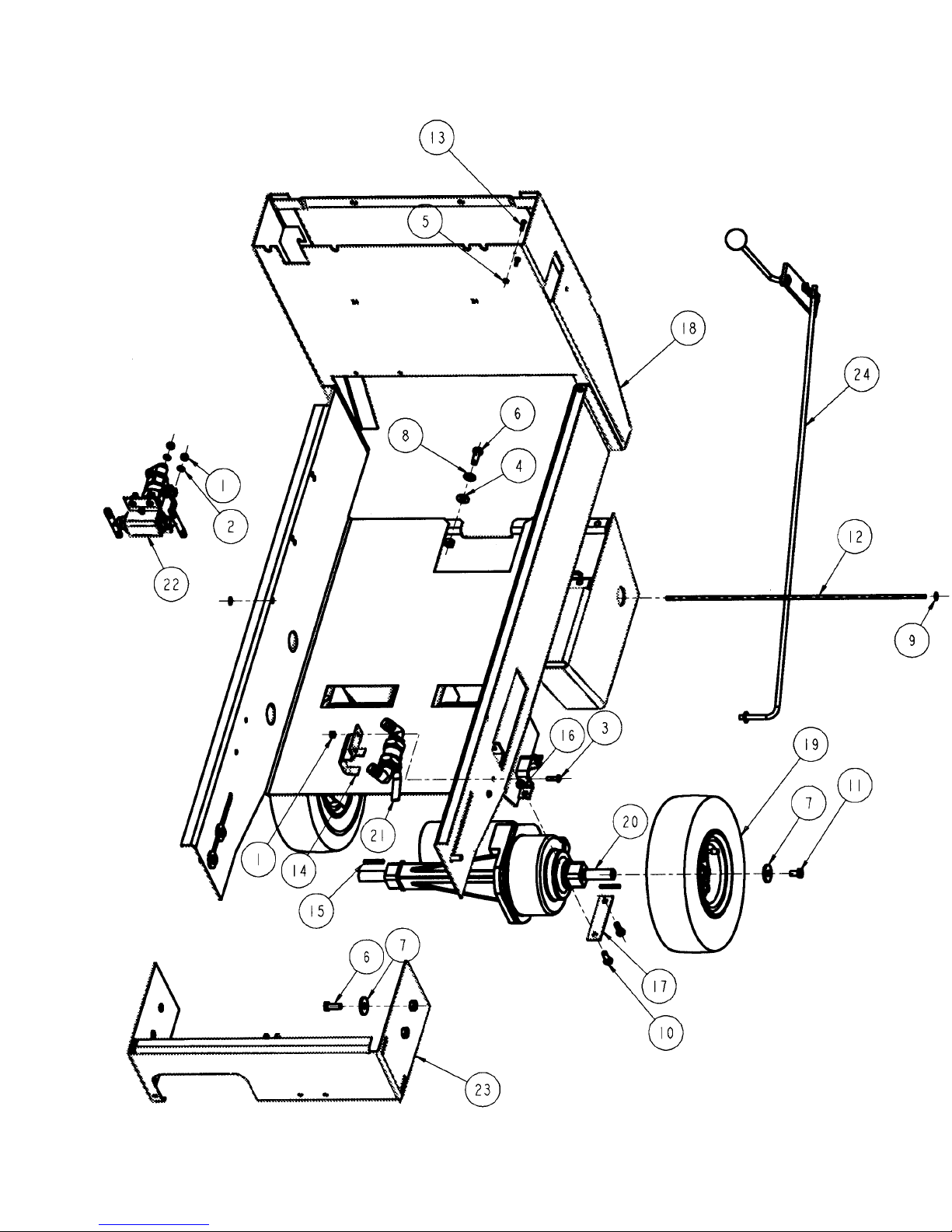
MAIN VIEW “C” – EXPLODED VIEW
(Ref. Drawing 31179)
46
Page 47

MAIN VIEW “C” PARTS LIST
(Ref. Drawing 31179)
ITEM QTY PART # DESCRIPTION
1 4 01497 NUT - FINISHED HEX 1/4-20
2 4 01574 LOCK WASHER 1/4”
3 2 02053 SCREW - PHILLIPS ROUND HEAD MACHINE 1/4-20 X 7/8
4 3 02568 WASHER - PLAIN 5/16
5 2 02958 3/8-16 UNC GRADES
6 7 03320 SCREW - HEX HEAD CAP 3/8-16 X I .000
7 6 03321 WASHER - PLAIN .391
8 3 03736 WASHER - PLAIN 3/8
9 2 15365 FASTENER - ROD
10 4 16654 SCREW - HEX HEAD CAP 5/16-18 X 7/8
11 2 16671 SCREW - HEX HEAD CAP 3/8-16 X 5/8
12 1 16824 ROD
13 2 16924 SCREW - PHIL. PAN HD. #6-32 X 3/4”
14 1 17290 CLAMP
I5 2 18499 KEY, 3/16 SQUARE X 1.5
16 4 19513 NUT - HEX LOCK (NYLON INSERT) 5/16-18
17 2 30765 BRACKET, TRANSAXLE
18 1 30778 FRAME WELDMENT
19 2 30797 WHEEL, 11-1/2” DIA.
20 1 30848 TRANSAXLE L/R
21 1 31074 ASSEMBLY, DRAIN VALVE
22 1 31075 ASSEMBLY, SOLUTION VALVE
23 1 31085 WELDMENT - FRONT BRACKET
24 1 31180 SOLUTION CONTROL SYSTEM
47
Page 48

COVER ASSEMBLY PARTS LIST
(Ref. Drawing 31186)
ITEM QTY PART # DESCRIPTION
1 2 00600 SCREW – SLOTTED ROUND HEAD MACHINE #8-32 X ¾
2 2 02956 NUT – HEX LOCK (KEPS) #8-32
3 8 04735 SCREW – PHILLIPS TRUSS HEAD MACHINE #10-24 X 3/4
4 8 10892 NUT – HEX LOCK
5 1 15640 WARNING LIGHT
6 4 19945 SCREW – PHILLIPS TRUSS HEAD MACHINE ¼-20 X 5/8”
7 1 30767 COVER, TOP
8 1 30774 HINGE 21” LONG
9 1 30775 PLATE, HINGE
10 1 31082 TOP-COVER BRACKET
48
Page 49

WIRING DIAGRAM
(Ref. Drawing 31072)
Page 50

50
WIRING HARNESS
CONTROL FUNCTIONS
(Ref. Drawing 31084)
Page 51

WIRING HARNESS
POWER FUNCTIONS
(Ref. Drawing 31086)
 Loading...