

Page 1
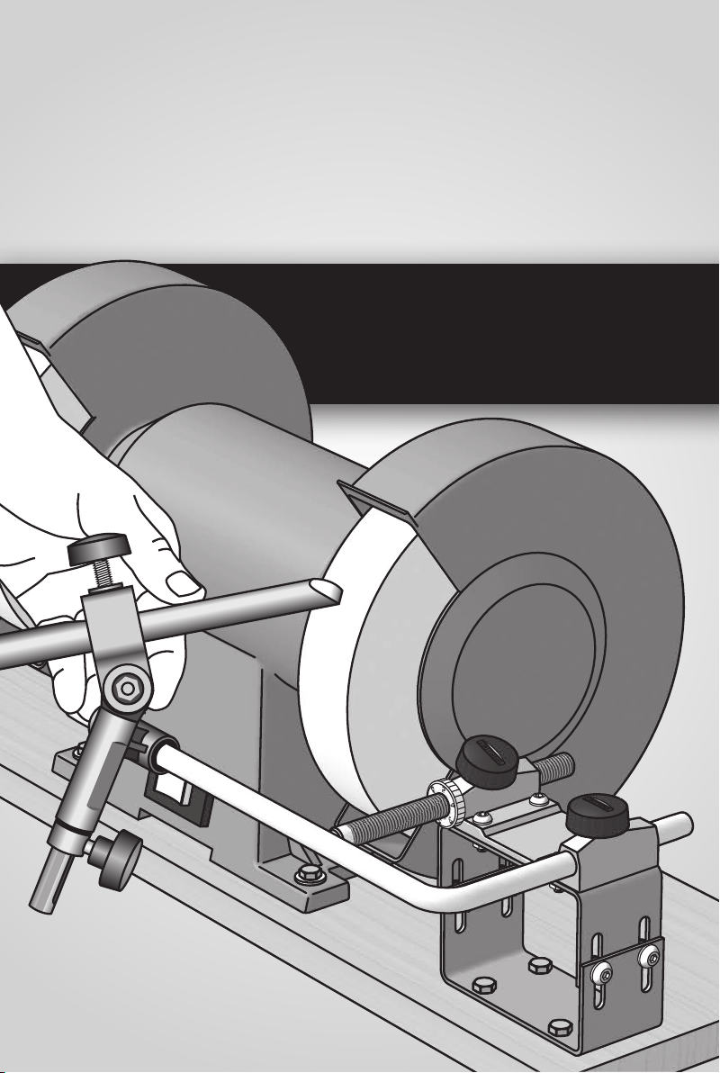
SHAPING
AND SHARPENING
WOODTURNING TOOLS
ON YOUR
BENCH GRINDER
Page 2

© Tormek AB 2012
All rights reserved.
BGM-10E
Edition 4.0
Tormek AB
Torphyttevägen 40
SE-711 34 Lindesberg
Sweden
9615-1205
Page 3

WITH THE BENCH GRINDER MOUNTING SET BGM-100 you can
now use the Tormek Jigs for woodturning tools and the patented
Turning Tool Setter TTS-100 also on your bench grinder!
These instructions are exclusively for HSS turning tools, since dry
grinding at high speed is not suitable for ordinary carbon steel tools
due to the risk of overheating and its aggressive steel removal.
The Tormek method makes a distinction between shaping and sharpening. Once you have created the desired shape on the tool, it is an
easy task to re-sharpen the tool exactly to the same shape every time.
After the shaping and sharpening you can go one or two steps
further towards achieving the nest edge by nishing on a Tormek
water cooled grinder. This is described in the handbook Sharpening
Woodturning Tools the Tormek Way, which comes with the TNT-300
Woodturner’s Instruction Box.
The handbook Water Cooled Grinding and Sharpening of Edge Tools
covers how to sharpen all your edge tools and the whole Tormek
system.
In the preparation of this handbook and the selection of the optimal
shapes and edge angles, professional woodturners and woodturning
educational centres around the world have been of great help.
We would like to thank you all for your experienced advice.
Good luck with your sharpening!
Torgny Jansson
and the Tormek team
Page 4

Page 5

Contents
Mounting the BGM-100 Set on Your Grinder ..................................... 6
About Bench Grinders ........................................................................ 9
Safety ............................................................................................... 10
Tormek Accessories for Your Bench Grinder ................................... 12
Turning Tool Setter TTS-100 ............................................................. 13
Gouge Jig SVD-185 .......................................................................... 16
Multi Jig SVS-50 ............................................................................... 18
Tool Rest SVD-110 ........................................................................... 20
Sharpening Bowl and Spindle Gouges ............................................ 21
Sharpening Exchangeable Cutters ................................................... 27
Sharpening Skew Chisels ................................................................. 29
Sharpening Roughing Gouges ......................................................... 32
Parting, Beading and Bedan Tools ................................................... 33
Sharpening Scrapers ........................................................................ 34
Sharpening Thin and Flat Parting Tools ........................................... 36
Sharpening Elliptical Spindle Tools .................................................. 36
Page 6
Mounting the BGM-100 Set on Your Grinder
The Bench Grinder Mounting Set BGM-100 can be mounted on grinders with wheel
diameters from 150 mm (6") to 250 mm (10"). You can either mount the grinder and
the BGM-100 on a self made wooden platform or you can mount the grinder and the
BGM-100 directly on the bench.
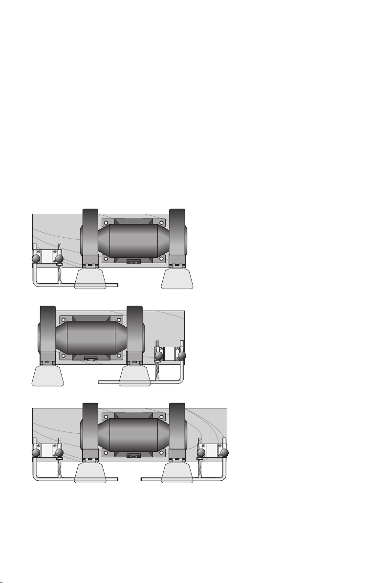
You can mount the BGM-100 set on the left or on the right side of the grinder whichever
suits you best. On some grinders, you need to remove the tool rest which comes with the
machine, in order to mount the Tormek Universal Support.
You can also mount a set on both sides, which gives you a versatile sharpening station.
You can mount the Tool Rest SVD-110 on the second wheel. Thanks to the instant mounting facility of the Tool Rest you can quickly exchange it for the Gouge Jig SVD-185 or for
the Multi Jig SVS-50.
Left side mount
Right side mount
Mount on both sides
6
Page 7
Contents: Bench Grinder Mounting Set BGM-100
•Universal Support with Micro Adjust 1 pc
•Base for the Universal Support 1 pc
•Height adjustable block 56–89 mm (2⁄–3½") 1 set
•Rubber feet 4 pcs
•BGM-10 Handbook 1 pc
•Prole Labels 1 set
•Bolt M6×12 with nut and washer 4 pcs
•Bolt M5×16 with nut and washer 4 pcs
•Bolt M6×40 with nut and washer 4 pcs
Making the platform
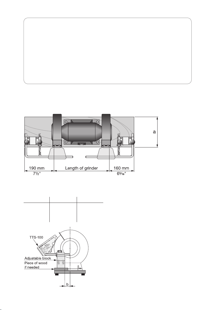
Use wood or plywood with a minimum thickness of 20 mm (¾"). The dimensions depend
upon your grinder, see sketches below.
Dimensions
Grinder size a b
150 mm (6") 200 mm (8") 10 mm (")
200 mm (8") 200 mm (8") 35 mm (1")
250 mm (10") 250 mm (10") 60 mm (2")
Length of platform
This depends on your grinder and if you use
one or two BGM-100 sets. The recommended
lengths on the left and on the right side differ
due to the asymmetrical Gouge Jig SVD-185.
Height of block
The optimal height of the block depends
on the design ofyour grinder. The best way
to make sure the jigs and tools don’t hit
the guards on your machine is by using the
Turning Tool Setter TTS-100 when setting the
height. If your grinder needs a block higher
than 89 mm (3½") place the adjustable block
on a piece of wood.
7
Page 8
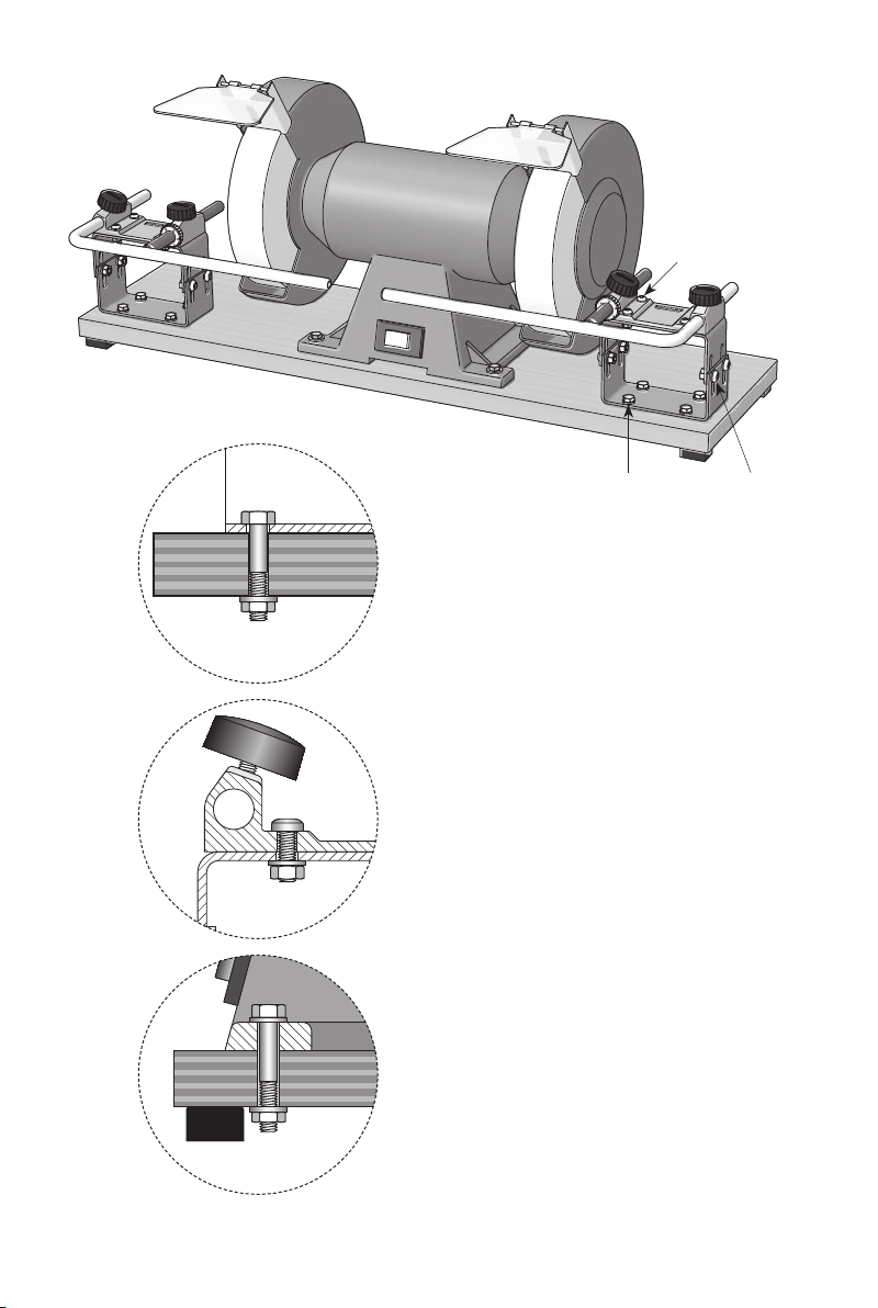
Bolt the block to
the platform.
Bolt the base for the
Universal Support to
the block.
M5×16
M6×12M6×40
Mount the grinder with suitable bolts,
which t the holes in the grinder. Use
washers under the bolt heads and nuts.
Mount the rubber feet and you will get
a steady platform with less vibration.
8
Page 9

About Bench Grinders
Using the right type of grinding wheel
Not all grinding wheels are suitable for the precision sharpening of edge tools. The standard wheels mounted on the grinder are often too hard and become glazed easily, which
reduces steel removal and causes overheating of the tool. Use an aluminium oxide wheel
with the right binding – not too hard to avoid glazing and not too soft to avoid grooves.
Wheel surface
The wheel surface must be kept fresh and clean. Worn grains must wear away so that
newones come into play. If not, the surface becomes glazed and the grains will rub
instead of cutting, which will increase the friction and heat development. Use a diamond
wheel dresser to maintain the surface in a good shape and condition.
Influence of heat on HSS steel
HSS steel can stand a much higher temperature than carbon steel without decreasing the
hardness. However, at the very tip of the edge which is very thin, the temperature can easily
rise to a level which will affect the hardness. Therefore grind cautiously at the tip of the
edge and do not allow it to become blue. Overheating HSS steel can cause a decrease
in the hardness by as much as 4 HRC, which shortens the life of the edge. If youcool it
in water, do not cool abruptly from a high temperature, since this can cause micro cracks
invisible to the naked eye.
Grinding dust
The ne dust from the grinding wheel and steel particles from the tool can be a health
hazard. It is best to use a dust extraction system, so the dust does not pollute the air.
Youmust use a separate extraction system and not the same system as for your wood
dust, since a spark could light a re in the inammable ne dust.
9
Page 10

Safety
A bench grinder can be dangerous if not handled with knowledge and respect. Follow the
safety instructions, which come with your machine. Pay special attention to the following
operational advice.
• Wear eye protection.
• Do not work near dry shavings or wood dust, since a spark
can light a re.
• Secure the platform on your bench to ensure that the grinder
does not move during operation. Use screws or a clamp.
• Use only the Tormek accessories shown in this presentation on
your bench grinder. Follow this instruction manual.
• Check that all setting screws and knobs are properly tightened
before commencing work.
• Do not hold your hand or ngers close to the wheel to avoid
the risk that they might slip and touch the wheel.
• Do not press the tool harder against the wheel than that which
enables you to keep full control of the grinding operation.
• Always keep a part of the tool on the wheel during grinding
and never let it slip wholly outside the wheel.
Using the Multi Jig SVS-50
Always let the jig rest on the Universal Support steadily before you carefully lower the tip
of the tool to touch the wheel. Maintain pressure all the time towards the Universal Support.
10
Page 11

Using the Tool Rest SVD-110
The platform must always be mounted so the surface points to or above the centre of the
wheel. The distance between the platform and the wheel must not exceed 2 mm (⁄").
Using the Universal Support as tool rest
The distance between the Universal Support and the wheel must not exceed 2 mm (⁄").
11
Page 12
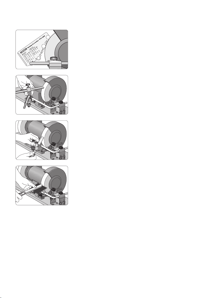
Tormek Accessories for Your Bench Grinder
Turning Tool Setter TTS-100
For setting the Gouge Jig SVD-185
and the Multi Jig SVS-50.
Gouge Jig SVD-185
For bowl gouges, spindle gouges
and elliptical spindle gouges.
Also for cutter/scraper tips.
Multi Jig SVS-50
For skews with a straight or curved
edge, roughing gouges, diamond
section parting tools, beading tools
and bedan tools.
12
Tool Rest SVD-110
For scrapers, thin and at parting tools,
hollowing tools and large cutters.
Page 13
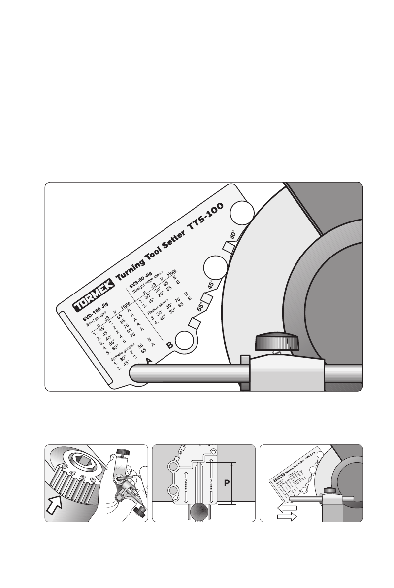
Turning Tool Setter TTS-100
No matter if you sharpen on a bench grinder or on a grindstone, the most difcult part in
sharpening woodturning tools is to replicate the shape and the edge angle. Tormek have
solved this problem by developing a key to instant and exact sharpening – the Turning
Tool Setter.
This setting device takes the guesswork out of sharpening. There is no longer any need
for trial and error to get the best edge shape for each turning operation. You just set the
jig and get the shape you have selected. Thanks to the patented design it works irrespectively of the stone diameter. You can go from a 150 mm (6") wheel to a 250 mm (10")
grindstone and achieve the same shape. The Setter is designed to work in conjunction
with the Gouge Jig SVD-185 and the Multi Jig SVS-50.
What determines the shape?
Three factors determine the shape of a gouge or a skew. By repeating them at each
shaping or sharpening you will get an exact replication of the shape every time.
JIG SETTING = JS PROTRUSION = P DISTANCE TO STONE
13
Page 14

Shaping and sharpening
The Tormek method makes a distinction between the shaping and sharpening (or resharpening) of a tool. When shaping you remove steel to achieve the shape and edge
angle you want. When sharpening you just touch up an existing shape to renew the sharpness. Generally you often say grinding for both shaping and sharpening.
If you have a Tormek machine, you can create the initial shape on your bench grinder and
nish the sharpening on your Tormek water cooled grindstone. You get the best of two
worlds; the fast steel removal from your high speed bench grinder and the ne surface
from your ne water cooled grindstone and the leather honing wheel. A ner edge gives
the wood a smoother nish with less need for sanding. A ner edge also cuts easier than a
rough edge and stays sharp longer before it needs re-sharpening.
Selected shapes and edge angles
There are quite a few manufacturers of turning tools and the shapes and edge angles vary
considerably. For example there are factory made skew chisels with skew angles from 15°
to 30° and the edge angles vary from 25° to 40°. Factory made bowl gouges have edge
angles from 30° to 60°. The wide range of shapes is the reason why Tormek up until now,
has not made recommendations for setting the shape and edge angle. In the past, we
have offered the technique and left each turner to nd his or her own geometry.
However, after having been in contact with many turners around the world, we now see
the need for an aid to the quick setting of the jig and also for advice about some suitable
shapes and edge angles. This newly developed Tormek Turning Tool Setter TTS-100 offers
both. The geometries, i.e. the shape and edge angle have been selected after consulting
experienced turners and should satisfy most needs.
Which shape should I use?
The Turning Tool Setter is delivered with a Selection Chart (pages 21 and 29) where
you can see which shape is suitable for your current type of turning. These geometries are
recommended by experienced woodturners and recognized woodturning training workshops around the world, e.g. Craft Supplies in the USA and Drechselstube Neckarsteinach
in Germany.
Of course you can also sharpen with geometries other than the shapes provided by the
TTS-100 Setter. If you have an existing edge geometry you can use the Marker Method or
the Spacer Block Method for setting the edge angle at the re-sharpening (page 26).
14
Page 15
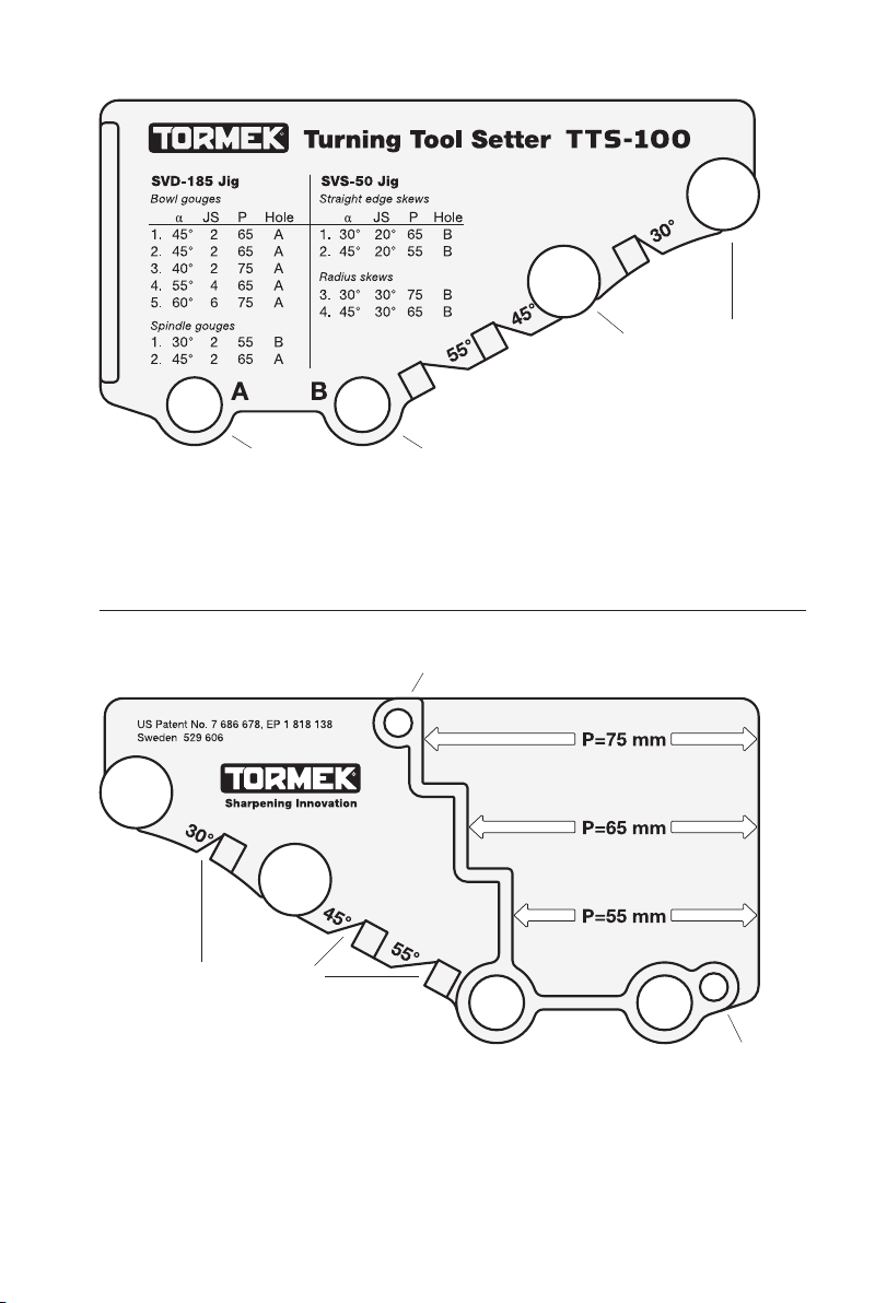
Outer hole Inner hole
Side 1
There are two holes for the Universal Support, A and B.
The type of tool and prole you require decide which hole to use.
Storage Magnet
Edge angle measuring grooves
Metal contact discs
Side 2
This side has stops for the recommended protrusions of the tool in the jig (P).
Storage
Magnet
15
Page 16
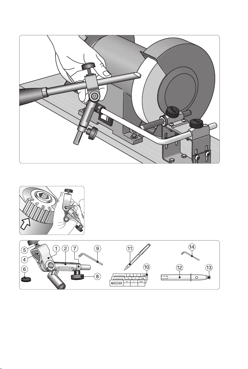
Gouge Jig SVD-185
The jig works on the Universal Support. The edge angle is set by moving
the support back and forth. The Micro Adjust facilitates a precise setting.
The tool holder can be set in
any position from 0 to 6 and
locks with the Allen key (9).
Parts
The jig comprises a tool holder (1) which runs in a sleeve (2). The tool is aligned with a disc
(4) and tightened with a knob screw (5). There is a washer (6) for wide gouges. The stop
ring (7) can be set for a convex bevel with a screw (8). The setting can be noted on a special prole label (10), which is attached to the ferrule. A special pen which works on these
labels, is included (11). For cutter/scraper tips there is a shaft (12) with a mounting screw
(13) and a 2,5 mm allen key (14).
16
Page 17
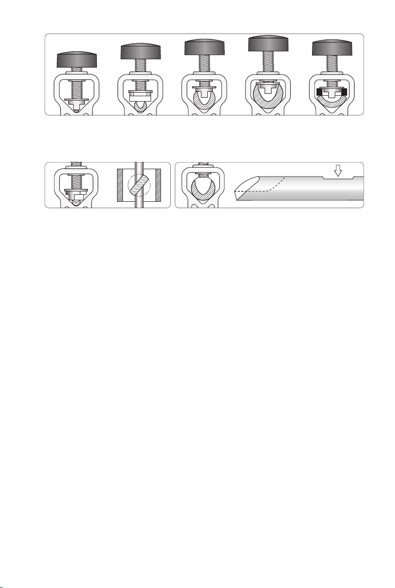
a b a a c
The special locking disc fits any size of tool, which is automatically aligned in the same position
every time it is mounted. The disc can be positioned either along (a) or across (b) the tool.
For wide gouges there is a removable washer, which fits on the disc (c).
The disc also works if placed diagonally.
Section seen from above.
For a large gouge with a short flute the locking disc is
removed. Grind a flat surface for repeatable alignment.
17
Page 18
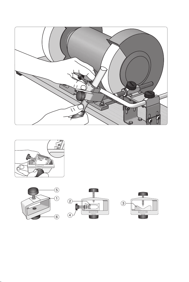
Multi Jig SVS-50
The jig works on the Universal Support. The edge angle is set by moving
the support back and forth. The Micro Adjust facilitates a precise setting.
The seat can be set
straight or to any skew
angle from 0° to 45°.
Parts
This patented jig consists of a housing (1) and two interchangeable seats – one closed,
(2) and one open, (3). The seats can swivel and be locked with the screw (6) at any skew
angle between 0° and 45°. Skew chisels should have symmetrical bevels on both sides.
With this jig you mount the tool only once for grinding both the bevels. By turning the jig
upside down you can grind both of the bevels symmetrically.
18
Page 19
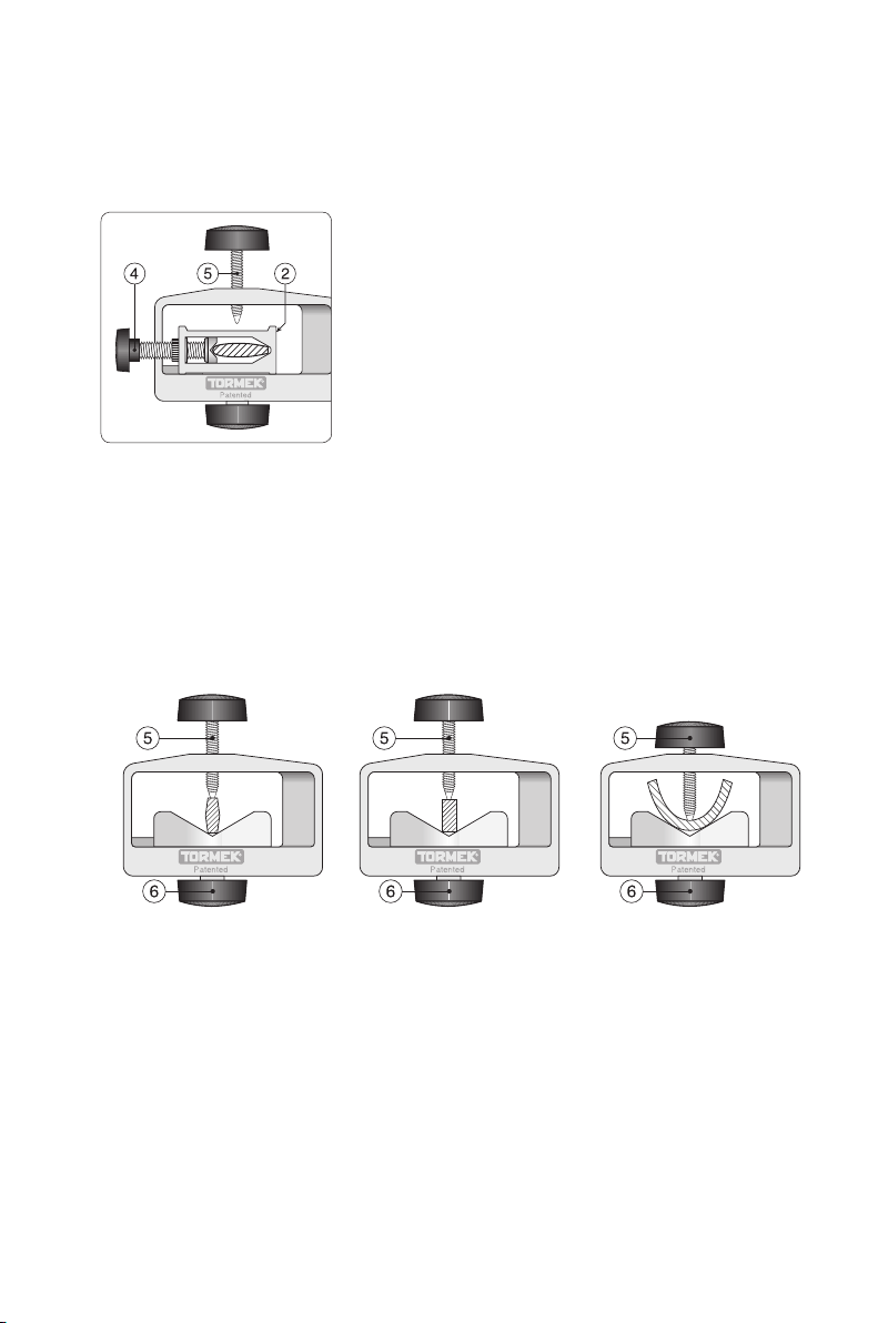
Closed seat
The closed seat has been developed for the precision sharpening of turning skew chisels
with an oval or square section and with curved or straight edges. Since the chisel is
mounted in the centre of the seat, the bevels are ground to exactly the same shape.
The turning skew chisel is mounted with a side screw (4). Max tool width 35 mm (1").
The closed seat (2) is for skew
chisels. The tool is fixed with
the side screw (4). The top
screw (5) is not used.
Open seat
The open seat, where the tool is xed with a top screw (5), is used for tools which have
the edge ground square across the shank, such as parting tools with a diamond section,
bedan tools and roughing gouges. Both seats are mounted with a bottom screw (6), which
also locks the chosen skew angle. A scale on each seat shows the skew angle.
The open seat is designed for tools which have the edge square across the shank.
The tool is fixed with the top screw in the housing (5).
19
Page 20
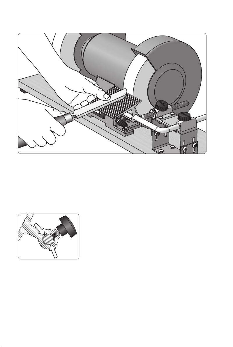
Tool Rest SVD-110
The Tool Rest works on the Universal Support. The edge angle is set by rotating the Tool
Rest on the support. It has a generous surface, 90×110 mm (3½"×4¼"), which permits a
safe and steady positioning of the tool towards the stone.
The bore is made with a special wedge shape, which increases the locking force by as
much as 250 %. You can lock the Tool Rest instantly at the chosen angle. This unique
design is patented by Tormek.
20
With the patented design, only the
sides of the tapered bore touch
the round bar – not the bottom.
This means that the locking action
increases by as much as 250 %!
Page 21
Sharpening Bowl and Spindle Gouges
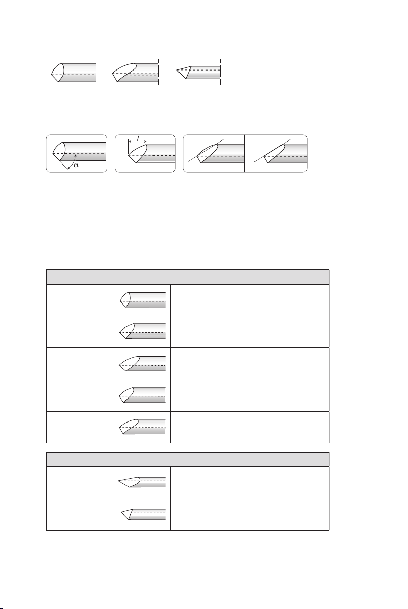
These are ground with the Gouge Jig SVD-185. Bowl and spindle gouges can have an
unlimited number of shapes. The variables are the edge angle (α) and the lengths of the
wings (l). The third factor is how the wings are shaped. They can be straight or convex.
Edge angle Length of wings Shapes of the wings
The chart below shows suitable shapes, which have been recommended by experienced
woodturners and recognized woodturning workshops. Decide which shape you want.
Once you have created the desired shape on the tool, it is an easy task to re-sharpen
it to exactly the same shape every time.
Bowl gouges
Standard profi le.
1
2
3
4
5
α=45°
α=45°
α=40°
α=55°
α=60°
JS 2
P 65
Hole A
JS 2
P 75
Hole A
JS 4
P 65
Hole A
JS 6
P 75
Hole A
Only lightly swept back wings.
For turners of all skill levels.
Irish profi le. Swept back wings.
Swing the tool 180° from side
to side.
With long swept back wings.
Somewhat aggressive.
For professional level turners.
The larger edge angle is benefi cial
when turning deep bowls.
“Ellsworth” shape.
Wings are pronounced convex.
Spindle gouges
1
α=30°
2
α=45°
JS 2
P 55
Hole B
JS 2
P 65
Hole A
For tight spots, detail work and
fi nest fi nish.
For professional level turners.
Standard profi le.
For turners of all skill levels.
21
Page 22
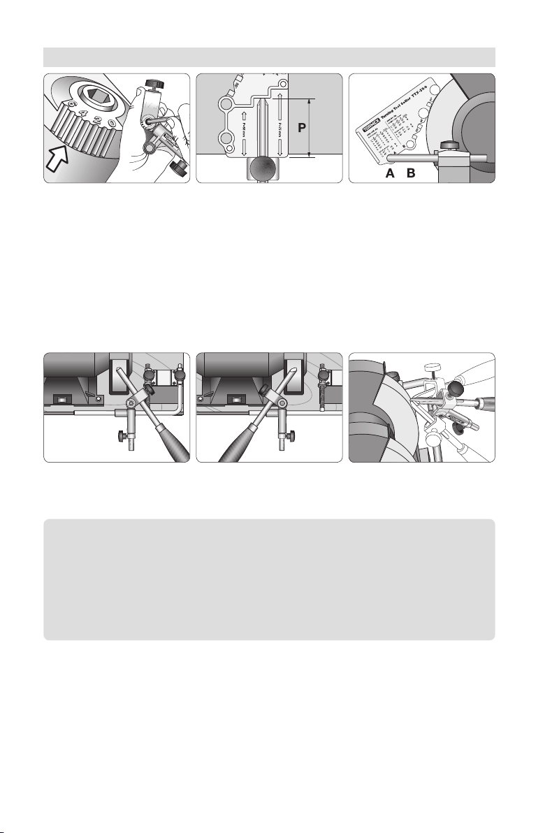
Shaping
Set the Jig, JS. Mount the tool with
the protrusion P.
Set the Universal Support.
Select hole A or B.
Select a shape from the selection chart and make the three settings which will give you
that shape. Grind with a light pressure so that you do not overheat the steel. Use the
whole width of the wheel to minimize grooving and to prolong the wheel life. Check your
grinding frequently to ensure that the gouge is ground evenly and acquires the shape you
want. Grind more on the spots where needed. If you need to change the prole considerably, grind one side at a time. This is easier than continuously swinging the tool back and
forth from left to right, and which could cause you to overgrind the centre of the edge.
Shape one side at a time and use the whole width of the wheel.
Finish with a full swing over the entire bevel.
Note Stick to the shape you have selected and do not switch from one
shape to another. Then you will get the full benefit of the Tormek TTS-100
Setter, since you can instantly replicate exactly the same shape every time.
Should you need a different shape, we suggest that you buy another tool
and grind it to your alternative shape. This way of working will give you more
time for turning and fewer interruptions for shaping and sharpening.
Shape and length of the wings
The three settings do not automatically give you the shape you have selected. Your hands
and eyes decide the nal shape within the limits of the three settings. You can acquire
different lengths on the wings by altering the width of your swing from side to side. A common problem is that the tip can be too pronounced. This is caused by grinding too much
on the wings. The cure is to grind more on the tip until you achieve the right shape.
22
Page 23
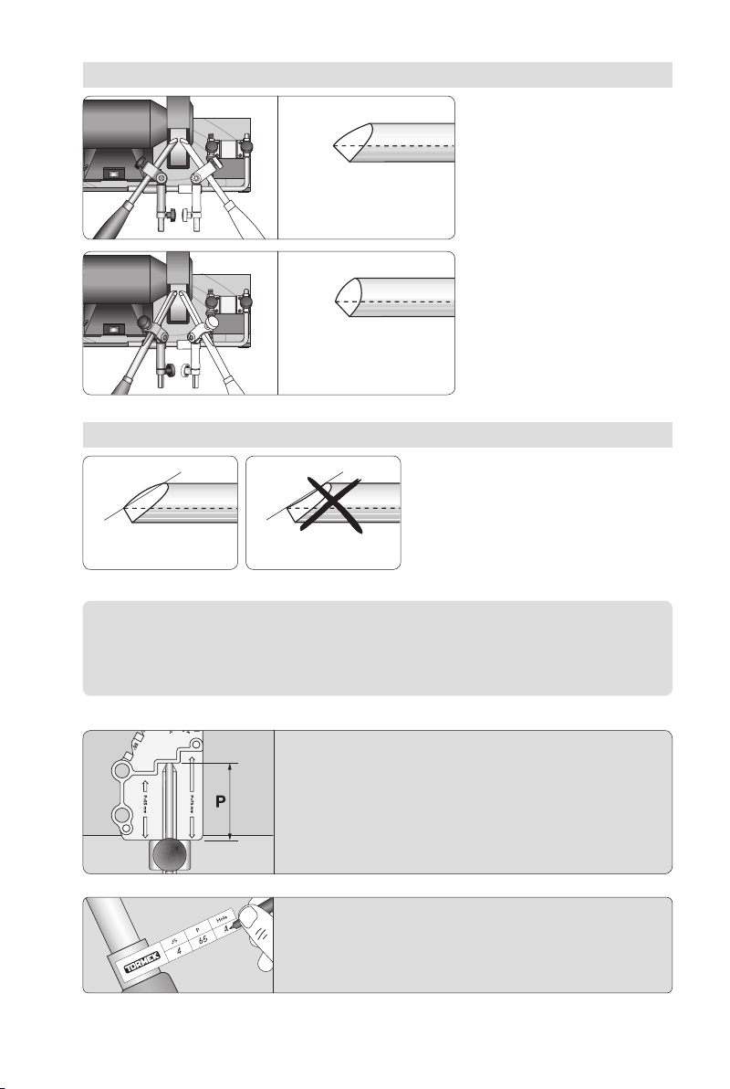
Length of the wings
Shape of the wings
Convex. Concave. Not suitable!
The width of the jig swing
determines the length of
the wings.
Full swing 180° –
Longer wings
Limited swing 90° –
Shorter wings
Grind so the wings become
symmetrical and slightly convex
or straight. They must never be
concave.
Note You decide how much grinding takes place on any one spot and
hence the final shape. If the wings tend to be concave, then grind more on
the centre of the edge.
Check that the protrusion has not decreased during the
shaping caused by that steel has been ground away
from the tip. If so, re-position the tool to the correct
protrusion and then make the final shaping. By doing
so, you will ensure that you exactly replicate the edge
geometry at future sharpenings.
Note the three settings on the Profile Label and put it on
the ferrule. Now you have the recipe of the shape and
you can exactly replicate it at each future re-sharpenings.
23
Page 24
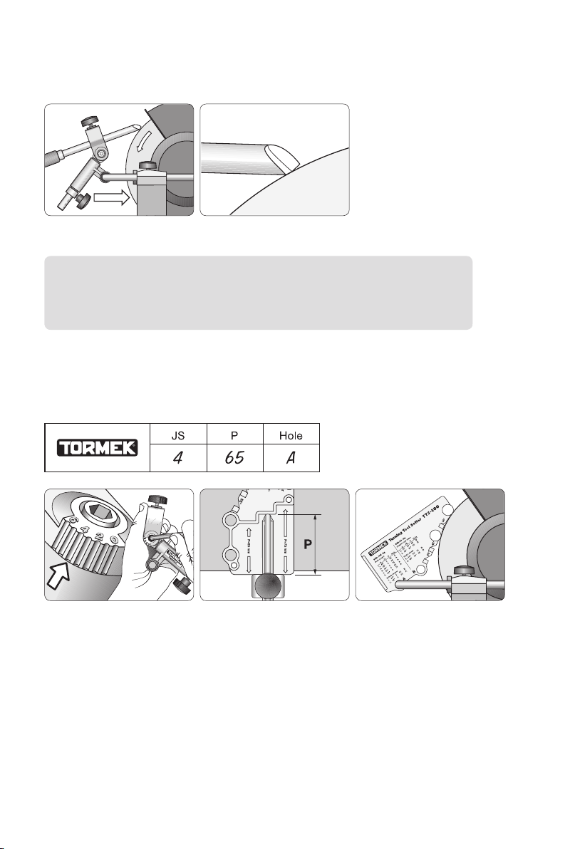
Rounding off the heel
You can round off the heel of the bevel by moving the Universal
Support towards the grinding wheel. Lock it properly.
Important Do not use the built in feature for moving the stop ring!
This is used only for the Tormek water cooled grinder, where the stone
rotates away from the edge.
Re-sharpening
Follow the settings that you have noted on the Prole Label and you will obtain exactly
the same shape every time, even when the stone wears and decreases in diameter.
Set the jig with the same
jig setting, JS.
Mount the tool with the
same protrusion, P.
Set the Universal Support
using the same hole, A or B.
Honing
If you don’t do the nal sharpening on a Tormek water cooled grinder, then remove the
burr and rene the edge with a honing stone. Hone the ute with a slip stone. A ner edge
cuts more cleanly, leaves a ner surface on the wood and stays sharp longer.
24
Page 25
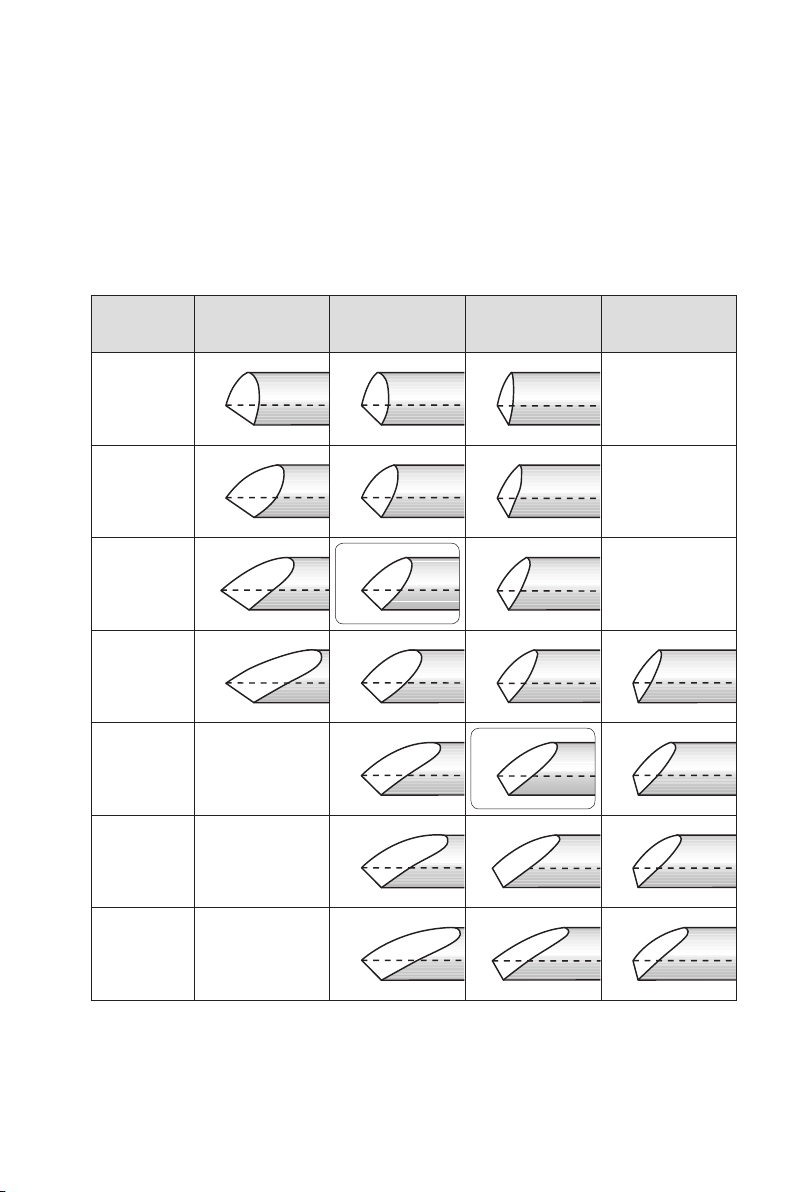
Other shapes
You can of course shape your gouge to a different geometry from those provided with the
TTS-100 Setter. This graph shows examples of shapes which you can achieve on a bowl
gouge at various jig settings and at various edge angles. The protrusion of the tool in the
jig P is 65 mm. The gouge is swung fully 180° from side to side. The edge angles are
approximate.
For these geometries you use the Marker Method or the Spacer Block Method at the resharpening. For the TTS-100 shapes JS2/45° and JS4/55° you use the TTS-100 method.
Jig Setting
JS 0
JS 1
JS 2
JS 3
JS 4
JS 5
Edge angle
35°
Edge angle
45°
*
Edge angle
55°
*
Edge angle
75°
JS 6
*The shapes JS2/45° and JS4/55° can be obtained with the TTS-100 Setter.
25
Page 26
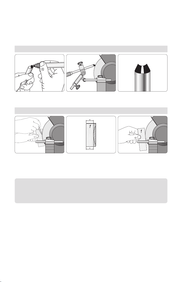
Replicating a non TTS-100 shape
For shapes different from those obtained with the TTS-100 setter, you can use one of
these methods to set the Universal Support and replicate the edge angle. Note the jig
setting JS and the protrusion P on the prole label.
1. The Marker Method
Colour the bevel with a marker. Turn the wheel by hand and adjust the Universal Support
until the colouring is removed from the tip to the heel.
2. The Spacer Block Method
This method requires a constant stone diameter to give an exact replication. Place a rectangular
wooden block close to the wheel and mark the contour. Draw a parallel line and cut away the surplus
wood. Now you have a wooden spacer, which lets you copy the setting of the Universal Support.
Note The Marker Method is always exact, but is not as fast as the Spacer
Block Method. The Spacer Block Method is exact only as long as the wheel
diameter remains constant.
26
Page 27
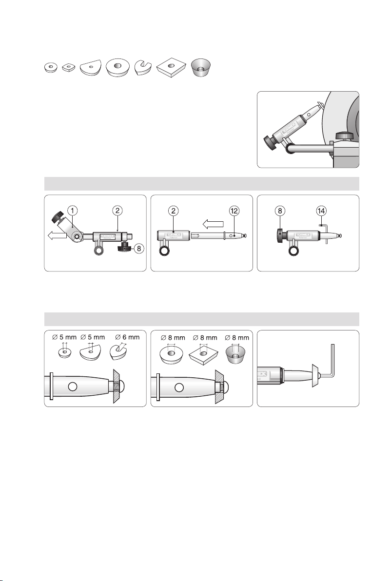
Sharpening Exchangeable Cutters
These are sharpened in the SVD-185 jig. There are various
types and sizes of exchangeable cutters for hollowing and
scraping. The holes vary from 5–8 mm. Due to the shoulder
on the shaft they can all be mounted with the same screw.
The cutters can be sharpened to their existing shape or to
a new shape.
Mounting the jig
Loosen and remove the screw
(8) and remove the tool holder
(1) from the sleeve (2).
Mounting the cutter
Cutters with 5 and 6 mm
(
⁄
"–¼") holes are located
bythe M5 screw.
Insert the shaft (12) into
the sleeve (2) as shown.
Cutters with 8 mm (
are located on a shoulder on
the shaft using the same screw.
⁄
") holes
Mount the screw (8). Lock
the shaft with the allen key
(14) when tightening.
Use the allen key (14),
which comes with the jig.
27
Page 28
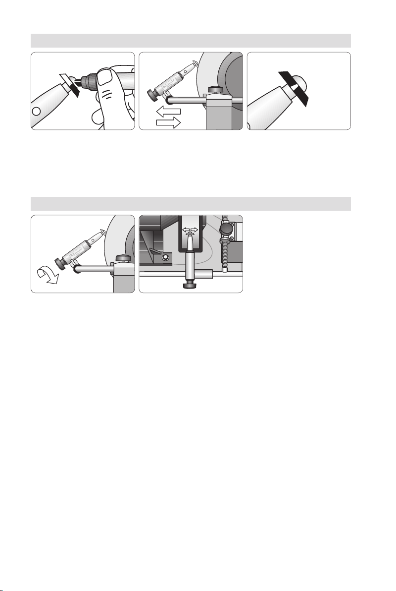
Setting the edge angle
Use the Marker Method for the first sharpening. Set the Universal Support so that the grinding
wheel touches the entire width of the bevel whilst rotating it by hand. At the correct setting,
the wheel removes the colouring along the whole width of the bevel.
Sharpening
Rotate the jig during the sharpening so you achieve an even
grinding around the whole circumference. Slide the jig sideways
on the Universal Support so the grinding wheel wears evenly.
Usea light pressure for the best result.
28
Page 29
Sharpening Skew Chisels
Bowl gouges
1
α=45°
JS 2
P 65
Hole A
Standard profi le.
Only lightly swept back wings.
For turners of all skill levels.
2
α=45°
Irish profi le. Swept back wings.
Swing the tool 180° from side
to side.
3
α=40°
JS 2
P 75
Hole A
With long swept back wings.
Somewhat aggressive.
For professional level turners.
4
α=55°
JS 4
P 65
Hole A
The larger edge angle is benefi cial
when turning deep bowls.
5
α=60°
JS 6
P 75
Hole A
“Ellsworth” shape.
Wings are pronounced convex.
Spindle gouges
1
α=30°
JS 2
P 55
Hole B
For tight spots, detail work and
fi nest fi nish.
For professional level turners.
2
α=45°
JS 2
P 65
Hole A
Standard profi le.
For turners of all skill levels.
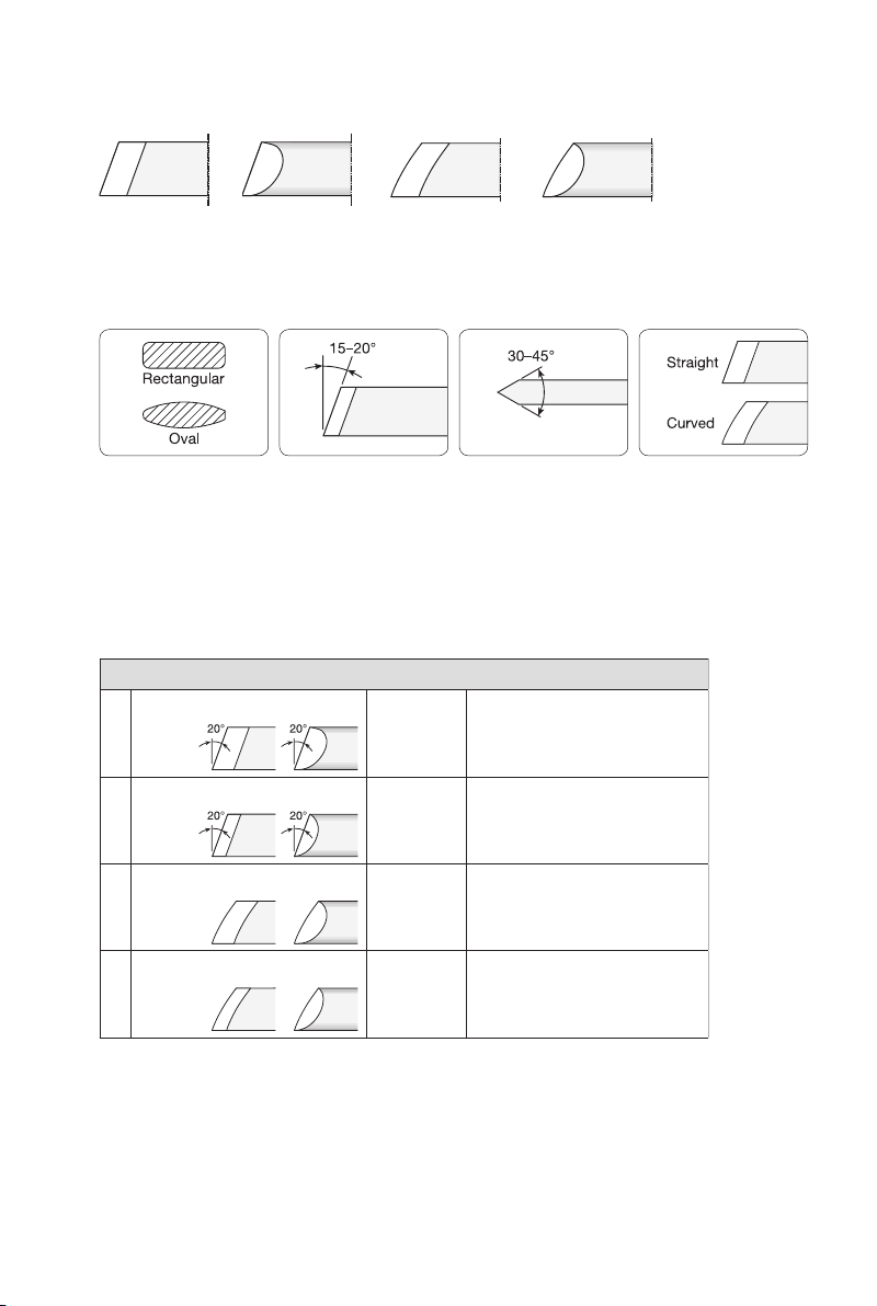
These are sharpened in the Multi Jig SVS-50 with the closed seat. There are many shapes
of skews since the section, skew angle and edge angle can all vary. A fourth dimension
can be added if you shape the edge to a convex curve.
The chart below shows suitable shapes, which have been recommended by experienced
woodturners and recognized woodturning workshops. Decide which shape you want.
Once you have created the desired shape on the tool, it is an easy task to re-sharpen
it to exactly the same shape every time.
Skews
1
2
3
4
Straight edges
α=30°
Straight edges
α=45°
Radius edges
α=30°
Radius edges
α=45°
Flat
Flat
Flat
Flat
Skew angle Edge angle Edge shapeSection
JS 20°
P 65
Oval
Hole B
JS 20°
P 55
Oval
Hole B
JS 30°
P 75
Oval
Hole B
JS 30°
P 65
Oval
Hole B
For tight spots, detail work and
fi nest fi nish.
For professional level turners.
For broad application.
Easier to control than
a 30° edge angle.
For tight spots, detail work and
fi nest fi nish.
For professional level turners.
For broad application.
Easier to control than
a 30° edge angle.
29
Page 30
Shaping
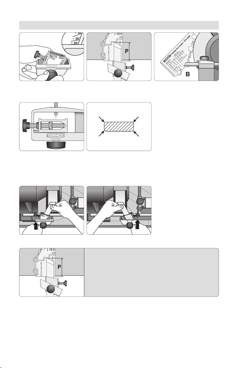
Select a shape from the selection chart. Then set the jig, JS.
Check that the tool is correctly
aligned so that the shape will
be exactly replicated when
re-sharpening.
Mount the tool with
the protrusion, P.
If your skew has sharp corners,
you should round them off before mounting the tool. This will
help ensure a correct alignment.
Check that the protrusion has not decreased during the
shaping. If so, re-position the tool to the correct protrusion and then make the final shaping. By doing so, you
will ensure that you exactly replicate the edge geometry
in the future.
Set the Universal Support.
Use hole B.
Grind with a light pressure so
you do not overheat the steel.
30
Page 31
Oval section
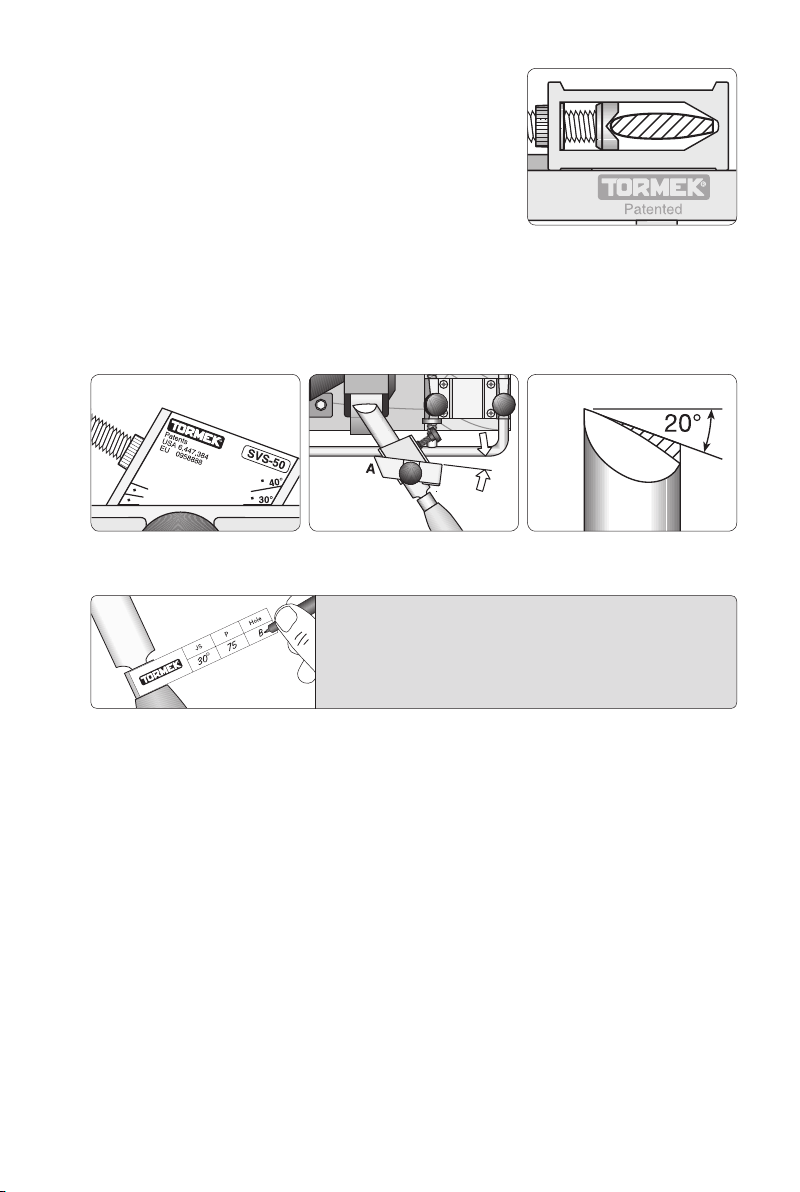
Thanks to the patented design of the SVS-50 jig it
is just as easy to shape an oval skew as an ordinary
skew with a rectangular section. The wide base of
the seat ensures an accurate alignment and a steady
running on the Universal Support.
Curved edge
You can shape the edge so it becomes convex by pivoting the jig on its bevelled corner, A.
To achieve a suitable curve you set the jig with a larger skew angle. For a skew with a 20°
skew angle, you set the jig on JS=30°. Now grind only the low point so the curve meets
the long point as a tangent.
Set the jig on 30°. Pivot the jig on the bevelled corner A. Grind the low point only.
The seat must all the time rest on the Universal Support.
Note the three settings on the Profile Label and put
it on the ferrule. Now you have the recipe for the
shape and you can exactly replicate it at each future
re-sharpenings.
Re-sharpening
Make the three settings noted on the Prole Label carefully and you will obtain exactly
the same shape every time even when the stone wears and decreases in diameter.
Honing
If you not do the nal sharpening on a Tormek water cooled grinder, then remove the
burr and rene the edge with a honing stone. Hone the ute with a slip stone. A ner
edge cuts more cleanly, leaves a ner surface on the wood and stays sharp longer.
Other shapes
You can of course shape your skew to a geometry different from those provided with the
TTS-100 setter. Set the jig to the existing skew angle or to a new angle of your choice.
(from 0° to 45°). Note the skew angle JS and the protrusion P on the prole label so you
can replicate the shape. To set the Universal Support for replicating the edge angle, you
use either the Marker Method or the Spacer Block Method. This is explained for gouges
on page 26.
31
Page 32
Sharpening Roughing Gouges
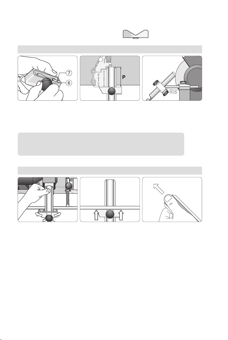
The Multi Jig SVS-50 with the open seat is used
Settings
Lock the seat with the bottom
screw (6) in the straight position
(0°). The seat should touch the
stop (7).
Mount the gouge protruding
(P) 75 mm and lock it with
the top screw (5).
Set the edge angle by
adjusting the Universal
Support. Use the Marker
Method.
When re-sharpening an existing edge angle, use the Marker Method
or the Spacer Block Method (page 26).
Sharpening
Roll the gouge on the Universal
Support. Slide the jig sideways
so that the wheel wears evenly.
Ensure that the entire flange
of the jig is in contact with
the Universal Support.
Grind until you can
feel the burr along
the entire edge.
Honing
If you don’t do the nal sharpening on a Tormek water cooled grinder, then remove the
burr and rene the edge with a honing stone. Hone the ute with a slip stone. A ner
edge cuts more cleanly, leaves a ner surface on the wood and stays sharp longer.
32
Page 33
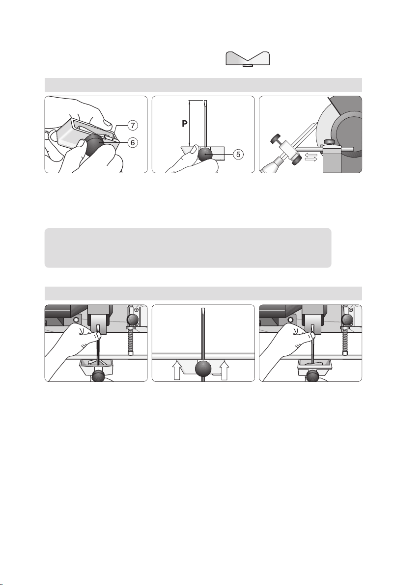
Parting, Beading and Bedan Tools
The Multi Jig SVS-50 with the open seat is used
Settings
Lock the seat with the bottom
screw (6) in the straight position
(0°). The seat should touch the
stop (7).
Mount the tool protruding
(P) 65 mm (2¾") and lock
it with the top screw (5).
Set the edge angle by adjusting
the Universal Support.
When re-sharpening an existing edge angle, use the Marker Method
or the Spacer Block Method (page 26).
Sharpening
Hold the tool vertically on
the Universal Support.
Ensure that the entire flange
of the jig is in contact with
the Universal Support
When the first side is ground
then turn the tool around 180°
and grind the other side.
33
Page 34
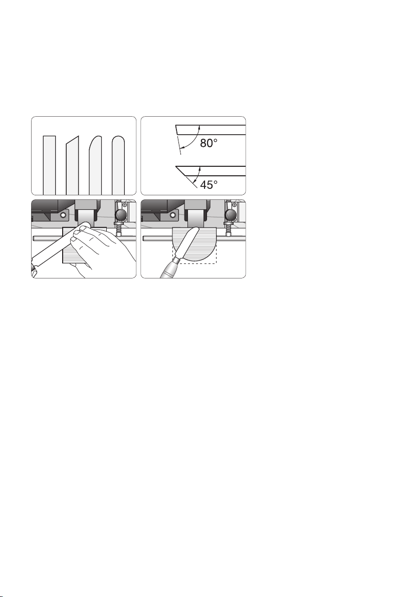
Sharpening Scrapers
These are sharpened with the Tool Rest SVD-110. Scrapers are available in different
shapes. You can also put a new shape on your scraper according to your own choice.
They usually come from the manufacturers with an edge angle between 70° and 80°.
Some turners prefer a smaller edge angle 65° or even down to 45 °.
The generous surface gives
you a good support.
When sharpening there will be a build up of metal on top of the edge which is the burr.
Unlike other turning tools the burr on scrapers is usually kept and not honed away. As
an alternative you can remove the burr and instead create a burr like “micro hook” by
burnishing (page 35).
The burr or micro hook causes the tool to cut the wood instead of scraping it as it would
do without the burr.
The burr consists of a sintered (almost melted) mixture of steel waste and abrasives from
the grinding wheel as well as solid steel which has been pushed upwards by the grinding wheel. The sintered mixture is not durable and will therefore decrease and wear away
during the turning. How fast it wears depends on how heavy it is, which depends on how
hard you have pushed the tool during the grinding. You need to regrind frequently to make
new burrs.
Due to the way the burr is created, its quality, strength and life changes from one sharpening to another and the way it cuts the wood is not always predictable. The size of the edge
angle also inuences the shape of the burr and the way it works.
34
For shorter tools you can trim
the surface to suit the tool.
Page 35
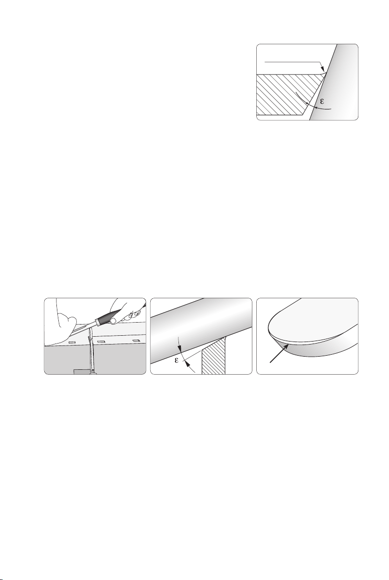
Burnishing the edge
There is an alternative method to make a scraper work as
a cutting tool. If you press with a hard steel rod towards
the bevel at an angle (ε) of approx. 5°, the tip will be bent
upwards creating a micro-hook. The pressure from the
rod compresses the steel, smoothes the small scratches
left by the grindstone and makes the hook shiny.
Micro-hook
The result is an even, sharp and durable micro-hook or
cutting edge. The method is called burnishing and gives
you a consistent and more durable hook than a burr.
Before using the burnishing method, you should grind the
bevel as evenly and nely as possible and hone the bevel
Burnishing the edge. The
tip of the edge is pressed
upwards forming a small
edge hook. (Here enlarged
for clarity)
as well as the top face to get a sharper and more durable
cutting edge.
There are special burnishing tools available. You can also do the burnishing by using a
12 mm (½") bowl gouge. Clamp the scraper in your workbench vice so you can hold the
burnishing tool steadily with both hands.
You must not burnish too heavily so that the hook is bent backwards. The tip of the hook
must point upwards to work. You should also adjust the pressure according to the edge
angle. A scraper with a large edge angle (70–80°) requires a larger pressure than one with
a smaller edge angle.
Clamp the scraper in your workbench and support your left hand on the bench. Use a light
pressure. Press the gouge on the bevel at an angle (ε) of approx. 5°. The hook is exaggerated
for clarity. You will notice how the burnishing has compressed the tip of the edge to a smooth
and shiny surface.
The function of the scraper after burnishing depends on how large a hook you put on
the edge. The size and shape of the hook depends on the edge angle of the scraper,
the burnishing angle (ε) and how hard you press the burnishing tool.
35
Page 36
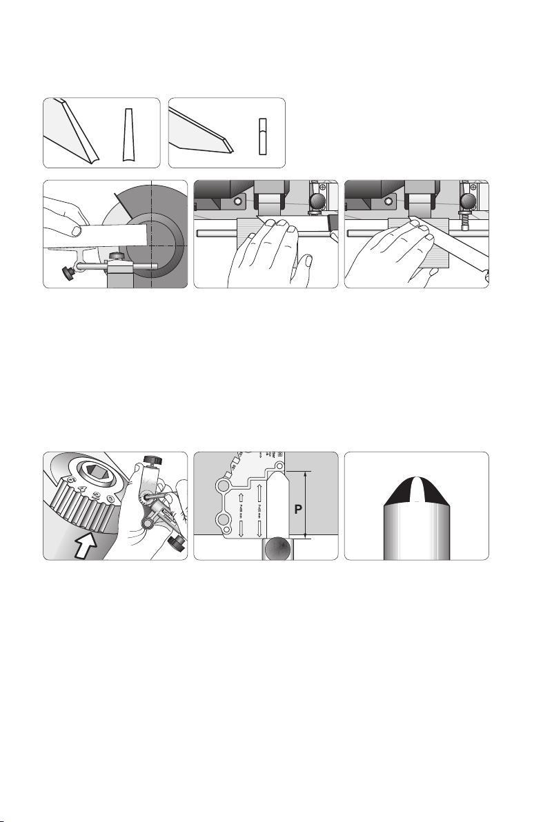
Sharpening Thin and Flat Parting Tools
These are sharpened with the Tool Rest SVD-110
Mark the centre of the wheel. Align and lock the Tool Rest so its surface points to the centre
of the wheel. Use the Marker Method to ensure that you have the correct alignment before
you commence grinding.
Sharpening Elliptical Spindle Tools
These are sharpened in the Gouge Jig SVD-185
On a common spindle tool, i.e. the Sorby Spindle Master, set the jig on No 1. Mount the tool with
75 mm (3") protrusion. Set the edge angle with the Marker Method (page 26).
36
Page 37

Page 38
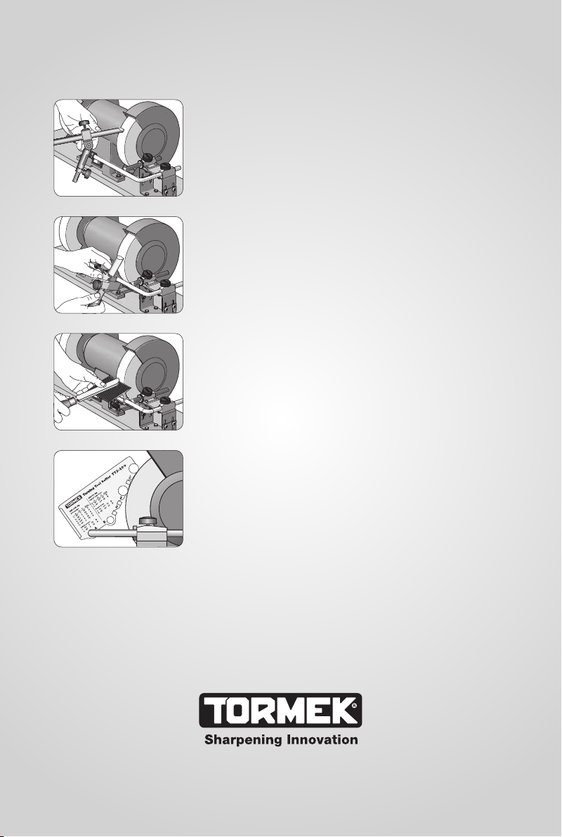
With the mounting set BGM-100 you can now use
the Tormek Jigs for woodturning tools ( SVD-185,
SVS-50, SVD-110 ) and the patented Turning Tool
Setter TTS-100 also on your bench grinder!
Gouge Jig SVD-185
Multi Jig SVS-50
Tool Rest SVD-110
Turning Tool Setter TTS-100
This handbook shows you in detail how to shape
and re-sharpen all your woodturning tools: bowl
gouges, spindle gouges, skews, scrapers and
parting tools. You also get instructions on how
tobuild the wooden platform to suit your grinder.
The Tormek method makes a distinction between
shaping and sharpening. Once you have created
the desired shape on the tool, the Turning Tool
Setter TTS-100 makes it an easy task to re-sharpen
the tool to exactly the same shape. This patented
setting device takes the guesswork out of sharpening. There is no longer any need for trial and
error to get the best edge shape for each turning
operation. You just set the jig and get the shape
you have selected. Thanks to the design it works
irrespectively of the stone diameter.
This instruction is exclusively for HSS turning tools,
since dry grinding at high speed is not suitable
for ordinary carbon steel tools due to the risk of
overheating and the aggressive steel removal.
 Loading...