

Tormax 1102, 1201, 1102 TTX Installation And Service Manual
®
Installation and Service Manual
1102/ TTX Swing Door Operator
TORMAX 1201 Swing Door Operator
Warning -
TORMAX USA Inc.
12859 Wetmore Road
San Antonio,TX 78247
210-494-3551
210-494-5930 (FAX)
888-685-3707
www.tormaxusa.com
info@tormaxusa.com
To reduce the risk of injury of persons - Use this operator only with swing doors.
Issue Date: 05/04/2018
P/N : US801918
Version: FW_3.11

TABLE OF CONTENTS
SECTION
Table of Contents
Important Information
Safety Warnings, Installation & Service, Glazing
Intended Installation Environment, Door Operation, ANSI/ BHMA
Operator Applications, Country Code, User mode with FCP
1. Modes of Door Operation
2. Components Overview
3. Applications
4. On-Board Programming Configuration Tool - Description
5. System Values for Application
Installation
6. Applications: Outswing 8-10 lbs. Spring Force Installation/ Commissioning
Outswing 18-20 lbs. Spring Force Installation/ Commissioning
Inswing 0” Reveal Installation/ Commissioning
Inswing 0”-6” Reveal Installation/ Commissioning
Double Egress Application Installation
Pair/ Double Egress Application Wiring
Pair/ Double Egress Application Commissioning
7. Adjustments:
1102/ 1201 Open Door Stop, 1201 Spring Tension
Frequently Used
8. Slim Line Header
Header Preparation
Application Illustrations
9. Programming with the FCP - Overview, Example
10. Commissioning with FCP
Commissioning, Adjustments
On-Board Codes 3, 6, 7 Descriptions/ BDM LED Display
11. Programming & Trouble Shooting Tables
12 Control Connection Diagram
13. Wiring Diagrams
Single Applications
Pair / Double Egress Applications
14. Technical Specifications:
Shaft Removal
T1253 Cable Plan
T1633 1201 Technical Information
T1634 1102 Technical Information
Electrical Requirements for Installation
T1753 Double Door Application
T1637 Basic Door Module (BDM) MCU42-BDM-A
T1638 Exterior Door Module (EDM) MCU42-EDM-A
T1640 Multi-Door Module (MDM) MCU42-MDM-A /B
T1639 Power Door Module (PDM) MCU42-PDM-A
T1691 Programming Interface Module (PIM) MCU42-PIM-A
T1757 Functional Control Panel (FCP) MCU32USIN-7-A
PAGE
2
3
4
5
6
7
8
9
10
11 - 12
13 - 14
15 - 16
17 - 18
19
20
21
22
23
24
25
26 - 28
29 - 30
31
32 - 36
37
38 - 42
43 - 47
48
49
50
51
52
53 - 54
55 - 56
57 - 58
59 - 60
61 - 62
63
64 - 65
2
Important Information
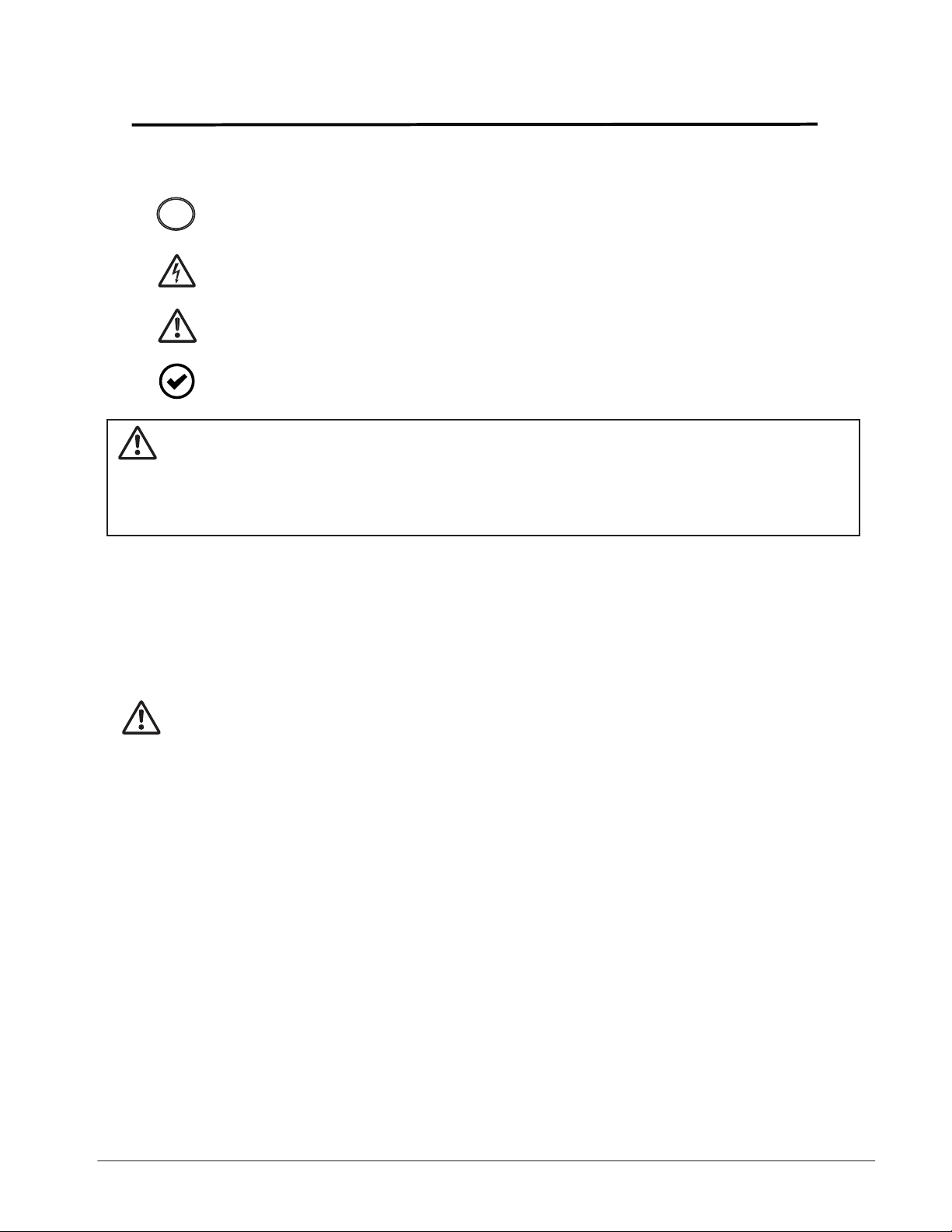
SAFETY/ WARNINGS SYMBOLS
NOTE indicates important information specific to the process or steps
!
being performed.
ELECTRICAL VOLTAGE indicates that electrical voltage is present
and that caution should be taken to prevent injury or property damage.
CAUTION indicates failure to follow instructions may result in personal
injury and/ or property damage.
OPTIONAL COMPONENTS indicates components that are not installed
in all systems.
WARNING - Failure to observe the information in this manual may result in
personal Injury or damage to equipment. To reduce the risk of
injury of persons use this operator only with pedestrian swing
doors.
Save these instructions for future reference.
Installation and Service
Any and all TORMAX equipment must be installed, serviced and inspected by an AAADM
Certified technician, to meet the current ANSI A156.10 and/ or ANSI A156.19 standard
and any local or state building codes.
The person responsible for the daily operation and maintenance of the system is referred to as
“End-User”.
It is the technicians responsibility:
1. Review the functions of the equipment with the end-user. Failure to do so, may lead to
the improper use, could cause injury to persons and/ or damage to the equipment.
2. Familiarize the end-user with the Daily Safety Check Decal and how to perform the
walk test procedures.
3. Illustrate to the end-user how to place the door out of service (turn off power or place
in P mode or OFF mode of operation), if the equipment does not perform as described
in the Daily Safety Check Decal.
4. Recommend to the end-user to have their equipment inspected annually by an
AAADM certified technician.
Glazing
The glazing material of all doors shall comply with the requirements of ANSI Z97.1, American
National Standard Performance Specifications and Methods of Test for Safety Glazing Material
Used in Buildings.
3

Important Information
Intended Installation Environment
The 1102/ TTX and the 1201 are non-handed swing door operators that can be used on
interior or exterior doors.
The operator is mounted above the door on the inside of the building. Any other use, or any
use exceeding this aim, is deemed as not used in accordance with its intended purpose.
The manufacturer will not be liable for damages resulting from such applications or warranty the
product. Arbitrary changes to the system will exempt the manufacturer from any liability for
damage resulting from this.
The 1102/ TTX is designed as a Low Energy operator to comply with ANSI A156.19
standard.
The 1201 can be utilized as a Low Energy operator and comply with ANSI A156.19
standard, or setup to operate as a Power Operated Pedestrian Door and comply with
ANSI A156.10 standard.
Upon completion of the installation the technician should perform an AAADM inspection to
ensure that the door complies to the appropriate standard ANSI a156.19 or ANSI A156.10
in which it is setup to operate within.
Door Operation
The 1102/ 1201 mode of operation is control by a 3-position switch (standard) or a (FCP)
Functional Control Panel (optional). The primary mode of operations are:
Off - The door remains in the closed position with lock engaged, but can
be opened by the Key Switch activating input.
Automatic - Two-way traffic, typical setting for normal operation. Allows the interior &
exterior sensors, Key switch and safety devices (if applicable) to operate
the door.
Hold Open - The door goes to the open position and remains there until the switch is taken
out of this position.
Upon a power loss the operation of the 1102/ 1201 operating system will function according to
specifications:
Immediate spring closing.
The operator functions as a manual door closure.
Lock function will operate to specification (fail secure/ fail safe).
Continued operation , if equipped with a battery backup.
ANSI/ BHMA A156.10, A156.19 standards - Knowing Act Switch
Doors activated by a manual switch must have the switch installed in a location
from which the operation of the door can be observed by the person operating
the switch. Refer to the latest revision of ANSI/ BHMA A156.10 or A156.19 for
location of Knowing Act switch and time delays.
4

Important Information
Operator Applications
The 1102/ 1201 are Surface Applied (SA) operators and are power open and spring close.
Basic configuration adjustments will be made with an on-board programming button.
The operator has 2 standard applications:
Outswing - The operator pushes the door open.
Inswing - The operator pulls the door open.
Within each standard application there are important points to know and consider during
the installation process.
Outswing: 8-10 lbs. of manual opening force (Low Energy ANSI A156.19) or Knowing
Act Door Activation (Power Operated Pedestrian Door ANSI A156.10)
18-20 lbs. of manual opening force ( Power Operated Pedestrian Door
ANSI A156.10)
InSwing: 0” reveal, non-handed arm
0“ - 6” reveal, handed arm
Country Code
The Country code is available in firmware V3.02 and above. The country code provides preset
values to aid the technician in installing the door to comply with ANSI Standard A156.19.
This does not eliminate the need for an AAADM inspection to be performed for compliance.
Additional adjustments may need to be made upon inspection.
“U” User mode on FCP
The User mode has two options:
UR - Ability to read specific programming parameters without changing the parameter.
UP - Ability to change programming parameters within a limited range.
Refer to programming table for specifics.
Recommend using “P” programming mode to have full range of adjustments on all parameters.
!
5
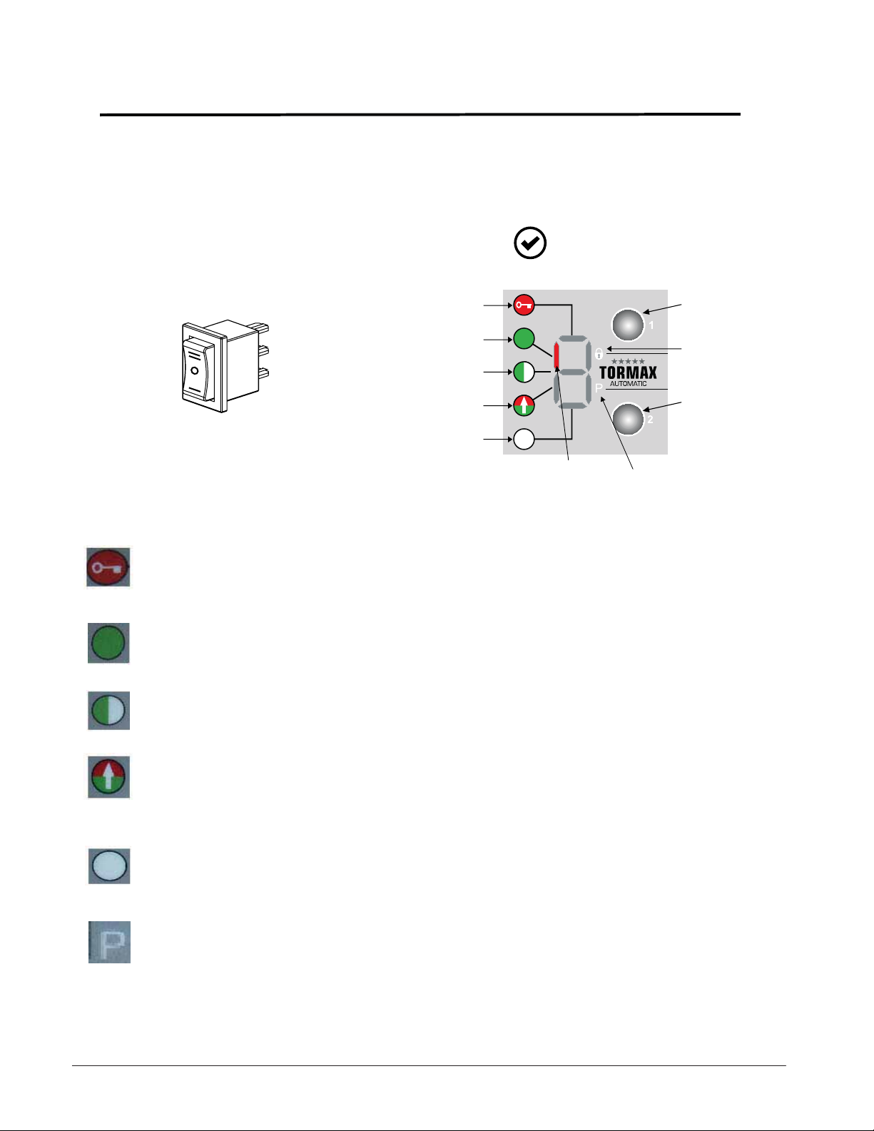
Modes of Door Operation
Modes of operation can be selected with either the standard 3-position switch or the
optional 6 position Functional Control Panel (FCP).
The technician will review the appropriate mode switch with the end-user.
HOLD OPEN
AUTO
OFF
1. OFF - The interior and exterior activators are inhibited after the door reached
the fully closed position, if an electric lock is present it will be activated. Door
will cycle open, if a signal is sent to the key switch input.
2. AUTOMATIC - Typical setting for normal 2-way traffic operation with interior
and exterior activators, key switch input and safety devices operating the door.
Standard:
1102/ 1201
#1) OFF Mode
#2) AUTOMATIC Mode
#3) REDUCED OPEN Mode
#4) EXIT Mode
#5) HOLD OPEN Mode
Optional:
1102/ 1201
www.tormaxusa.com
LED indicates current
operating mode
KEY 1
Electric door
lock LED indicator
KEY 2
#6) (P) MANUAL Mode
3. REDUCED OPERATING - Allows the door to open with a reduced opening
width. Activators and safety devices operate the same as automatic mode.
4. EXIT - (1-way traffic) Allows interior activator and key switch inputs to operate
the door. The exterior activator input is inhibited from opening the door while
the door is closed. When the door is opened/ closing the exterior activator
becomes operational and will re-open a closing door.
5. HOLD OPEN - Hold and maintains the door in the open position.
6. (P) MANUAL OPERATION - Allows the door to be used manually without the
use of sensors. Push and pull motion applied to the door to open and close
the door.
6
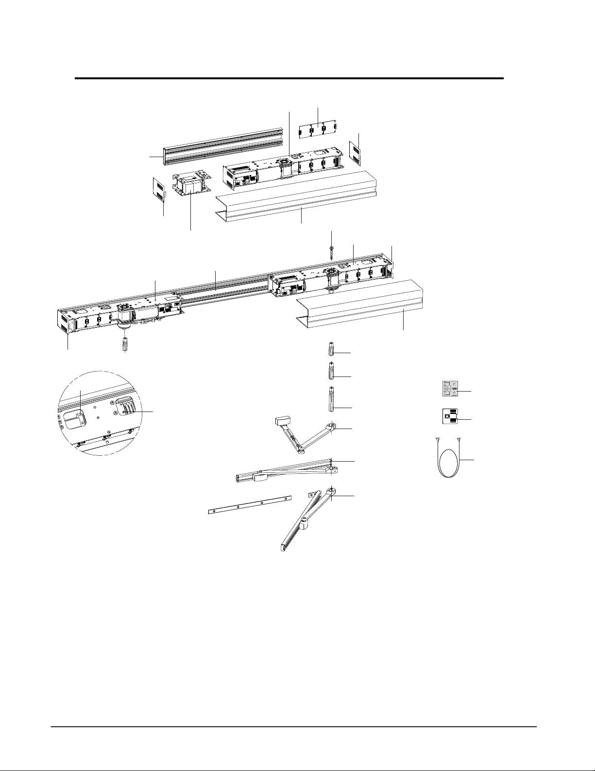
Components Overview
Single Door
15
1
13
Double Door
13
3
14
1
13
11
14
2
4
12
19
1
5
6
7
8
13
12
16
OPEN
AUTO
OFF
17
1 Primary drive TORMAX 1102/1201
2 Secondary drive TORMAX 1102/1201
3 Adjustment of spring force TORMAX 1201 only
4 Adjustment of internal open end stop
5 Shaft 2.48 in. (63 mm)
6 Shaft 3.22 in. (82 mm)
7 Shaft 4.84 in. (123 mm)
8 Out-Swing (Push) Arm 11.41/ 13.77 in. (290/350 mm)
9 In-Swing (Sliding Pull) Arm 13.77/ 19.68 in. (350/500 mm)
10 In-Swing (Slide/ Pull) Arm w/Panic 19.68 in. (350 mm)
(not available at this time)
9
10
11 Battery unit
18
12 Header cover
13 Side plate
14 Mounting profile
15 Upgrade modules MDM, PDM, EDM
16 Functional Control Panel (FCP) User interface (Option)
17 On/Off/Hold Open mode of operation switch (Standard)
18 Sync Cable for pairs
19 Shaft retaining bolt
7
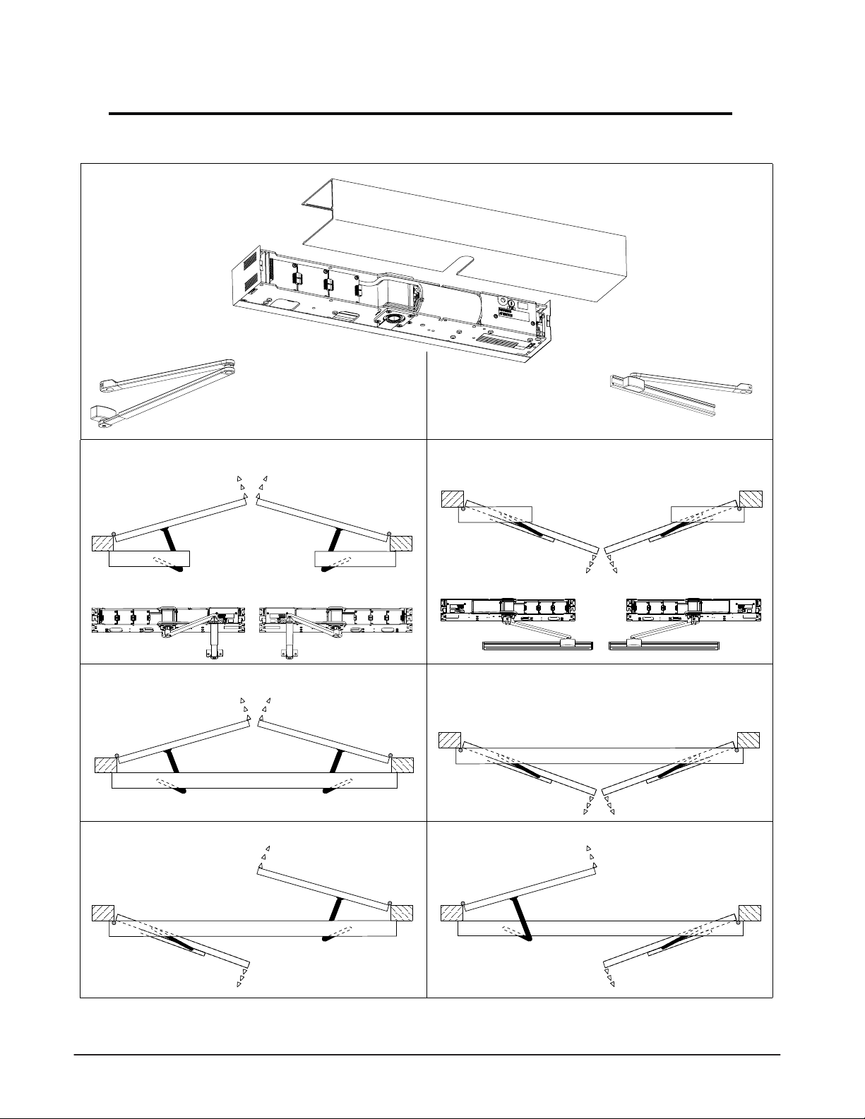
APPLICATIONS
Standard (Out-Swing) Push Arm Singles
Operator Non-handed
LH
Standard (Out-Swing) Push Arm Pair
Operator Non-handed
LH
Standard Double Egress Pair - RH
Operator Non-handed
RH
RH
Standard (In-swing) Pull Slide Arm Singles
Operator Non-handed
RH
Standard (In-Swing) Pull Slide Arm Pair
Operator Non-handed
Standard Double Egress Pair - LH
Operator Non-handed
LH
LHRH
RH
RH
LH
LH
8
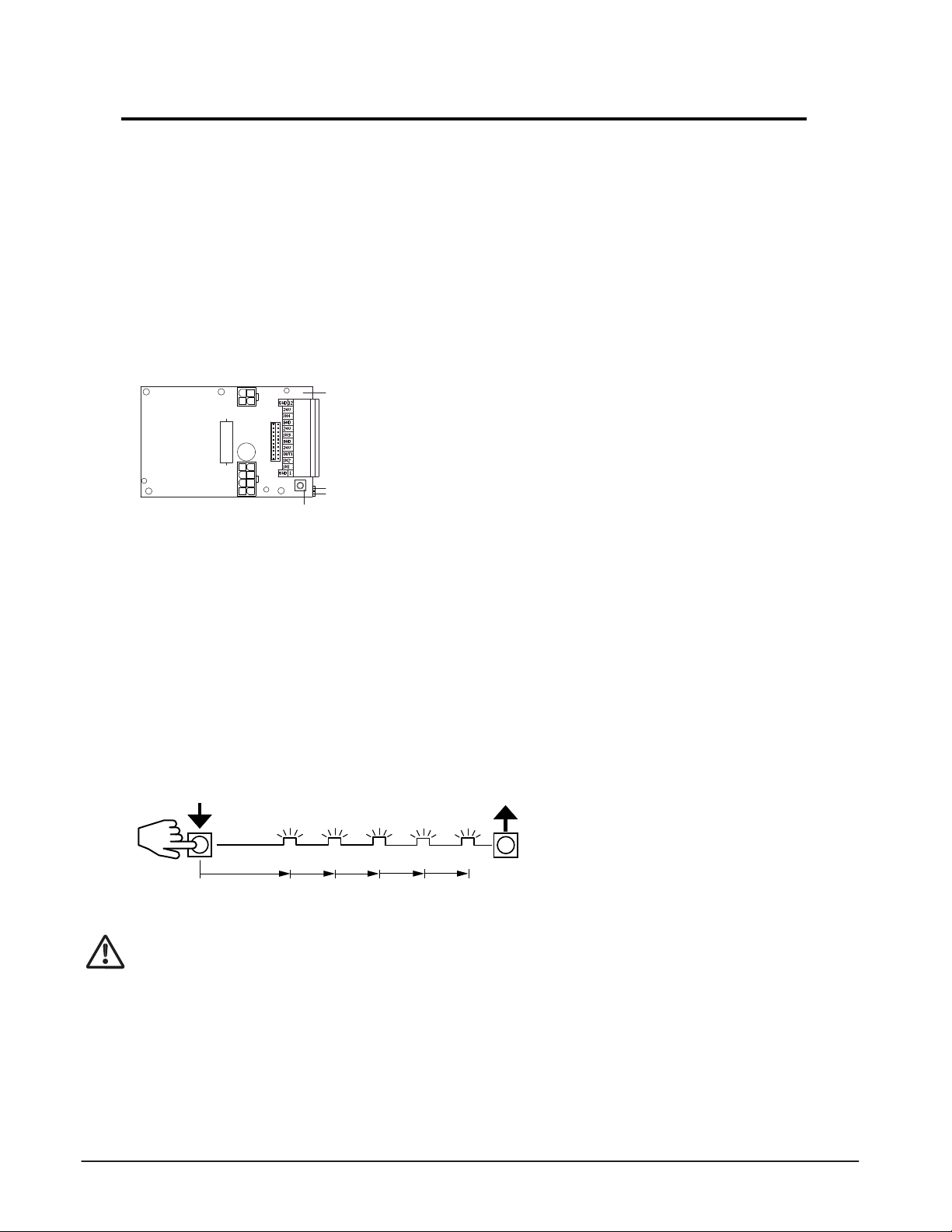
On-Board Programming Configuration Tool - Description
Overview
The On-board programming tool allows the installer to commission the operator without the
use of the FCP. If additional changes are needed i.e. time delay, push-n-go the FCP will be
required.
The on-board programming tool utilizes the programming button, green & yellow LEDs and
an audible tone device to aid the installer during the commissioning process. During the
commissioning process, the LED’s flashing sequence and audible tone will continually repeat
until a selection is made, then the audible tone and flashing sequence changes for the next
parameter selection.
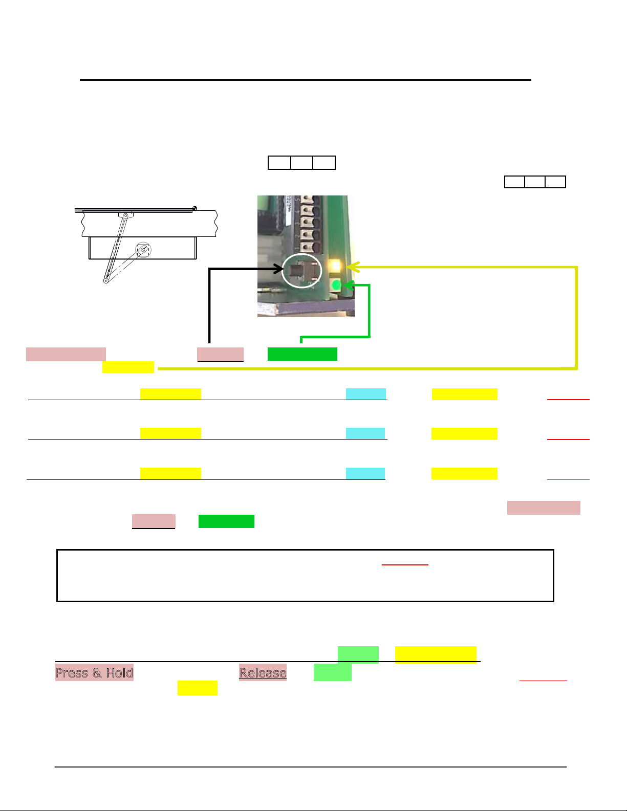
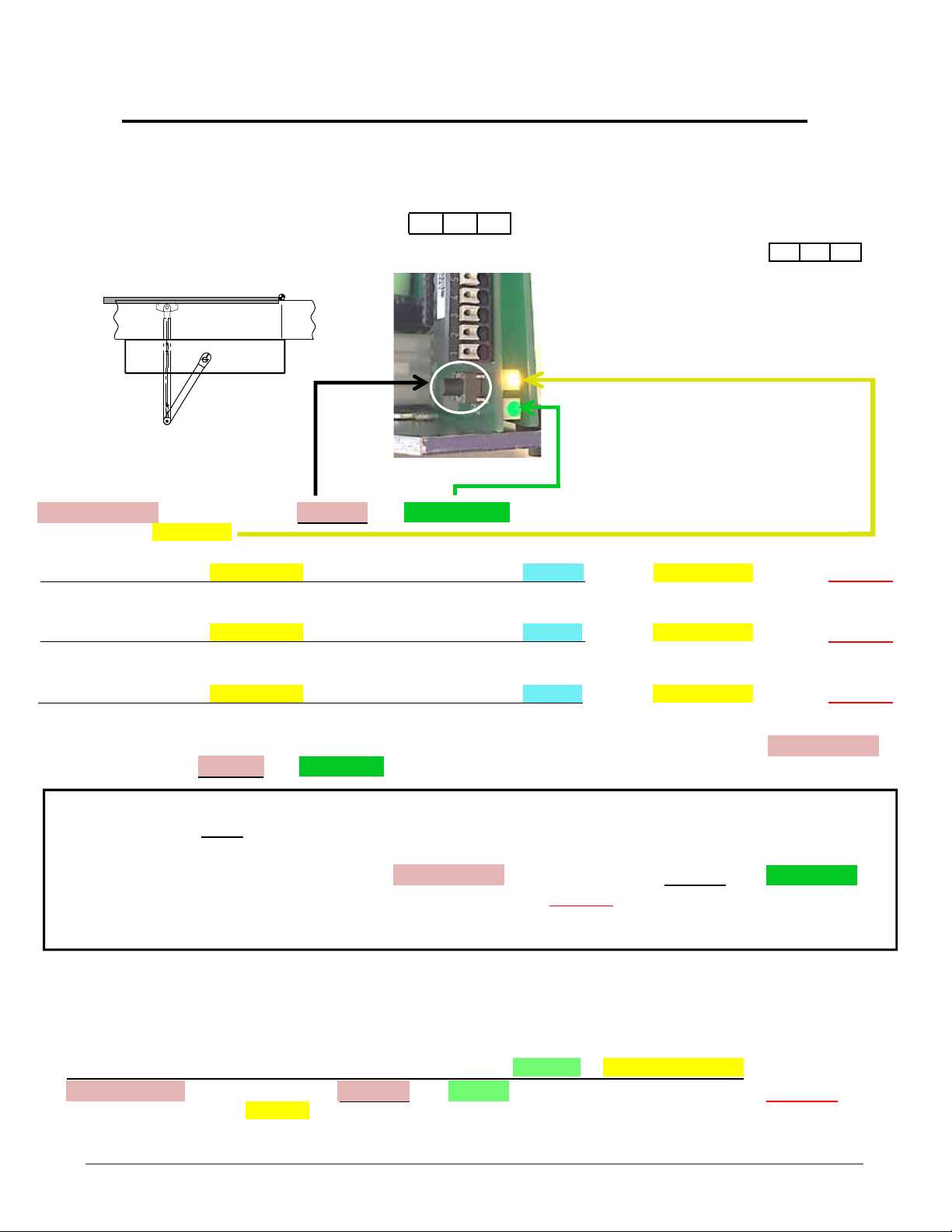
On-board Configuration Tool Familiarization
M
1
A
T1652_1
Programming functions can be launched by means of the programming button.
The GREEN LED supports parameter selection Release the button at the right point in time.
4
3
2
The YELLOW LED indicates the parameter by a series of flashes Press the button at the right point in time.
Programming Procedure – General
• Keep the programming button depressed. The GREEN LED starts to FLASH at one second intervals
for a short time. The number of flashes corresponds to the programming code as in the programming
table.
• Release the programming button after the required number of GREEN FLASHES.
Example: Code 5 “Factory Reset” (see below for codes)
Press Programming button
GREEN LED
3 s 1. 2. 3.
1 Base door module BDM
2 Programming Button
3 LED GREEN: status display (control system ready for operation)
or configuration display.
4 LED YELLOW: error display or configuration display
Release Programming button
This ends the programming step.
5.
4.
Programming Codes
In order to ensure the safety of the system, please follow the details of the programming steps in
the following pages.
Code 1: Commissioning (enter system values, preloads, performs learn)
Code 2: (Consult factory)
Code 3: Detecting/mask out safety features
Code 4: Spring pre-tension parameter (only applicable for TORMAX 1201)
Code 5: Factory reset (Reset all values, excluding operator type)
Code 6: Repeat commissioning (without entering system values, door preloads, performs learn)
Code 7: Preset value 1 = Low Energy (preset values for multiple parameters)
9
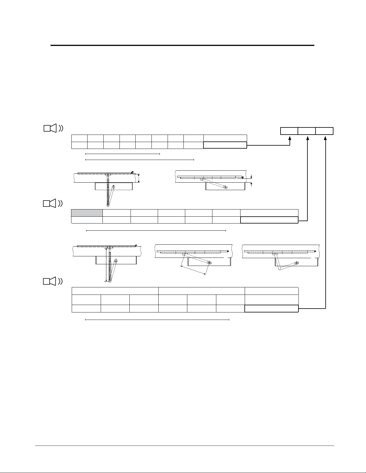
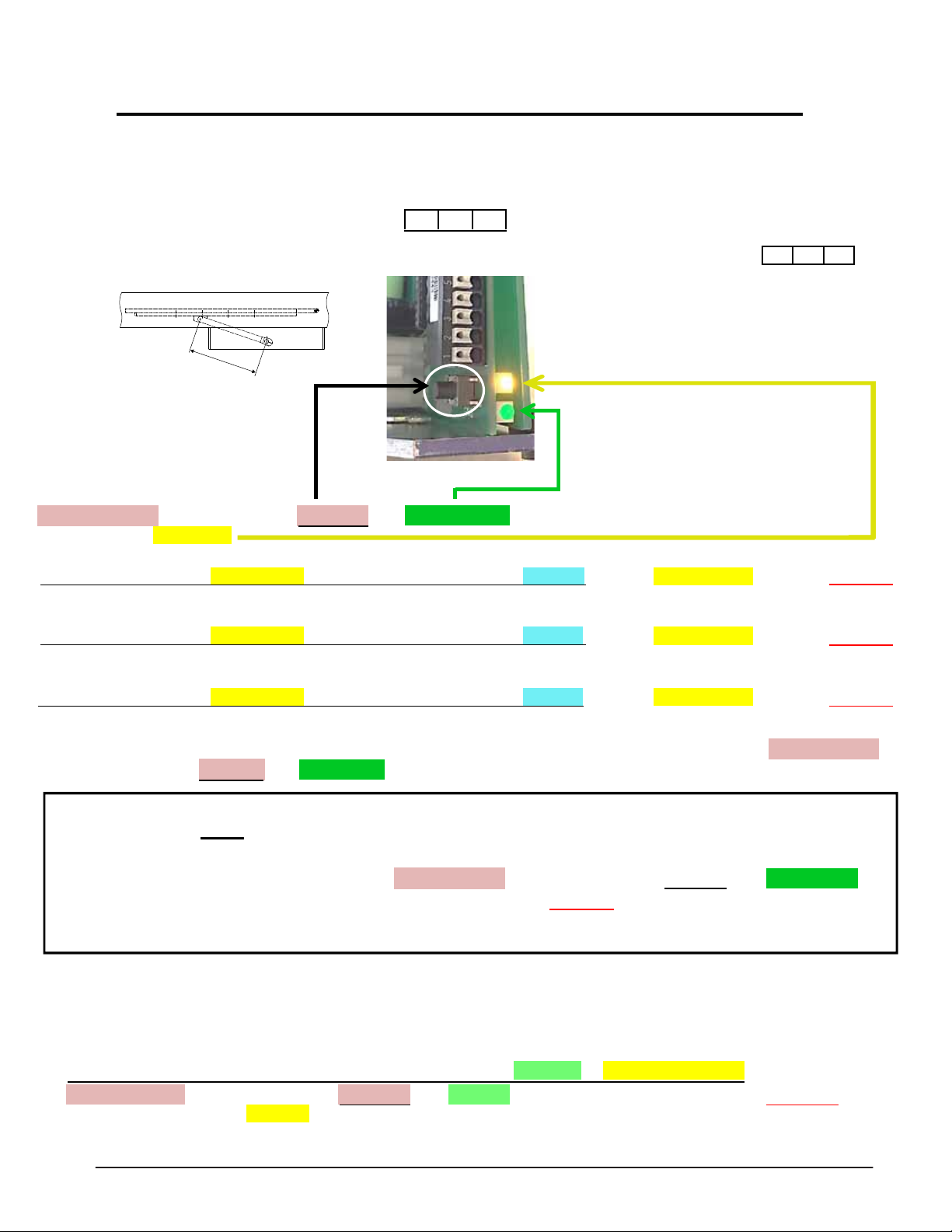
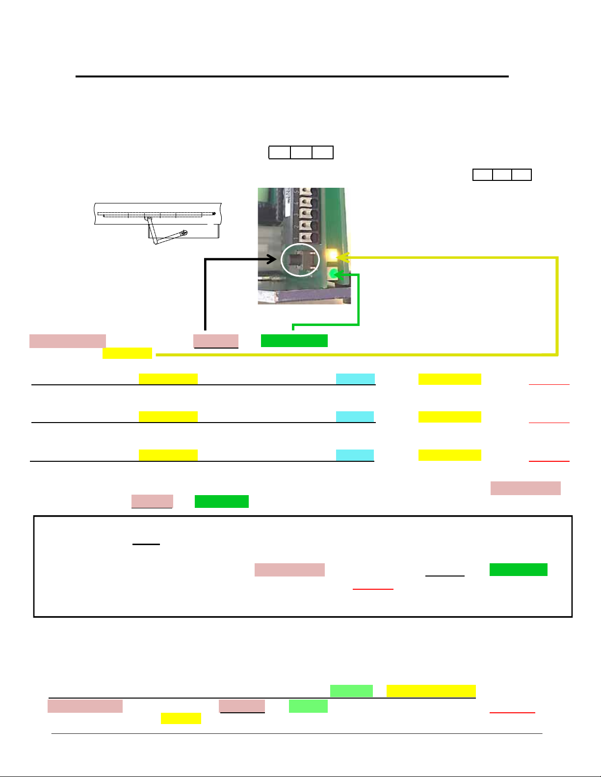
System Values for the Application
System Values
After installing the operator determine the 3 system values. Measure the dimensions
shown in the illustrations below, select each system value listed below the measurement.
Write these numbers down as they are referenced during commissioning.
Audible Tone
Number of Flashes
Audible Tone
Number of Flashes
Audible Tone
Number of Flashes
1
Door width
28” 32” 36” 40” 44” 48”
1 2 3 4 5 6 7 8
1102
1201
2
Reveal
0 - 2” 2 - 4” 4 - 6” 6- 8.5” 8.5 - 10.5” 10.5 - 12.5” Distance A
Yellow LED
Yellow LED
A
*52” *56” Door width
Value 1
Green LED
1 2 3 4 5 6 Value 2
C
3
Drive Arm
Outswing Inswing
11-3/8”
Custom 13-3/4”
A
A
Custom
B
1 2 3 4 5 6 Value 3
Yellow LED
A
Green LEDYellow LED
Lever length C
Green LED
System Values
B
10
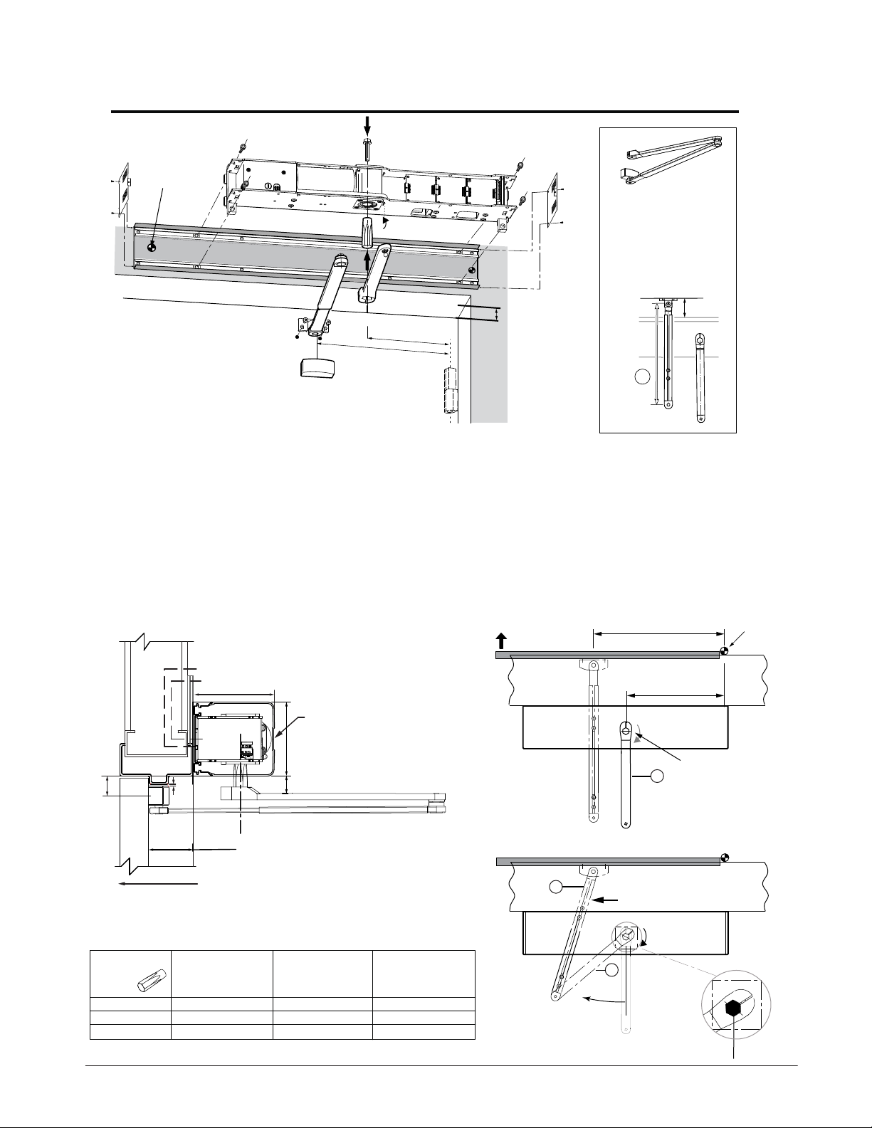
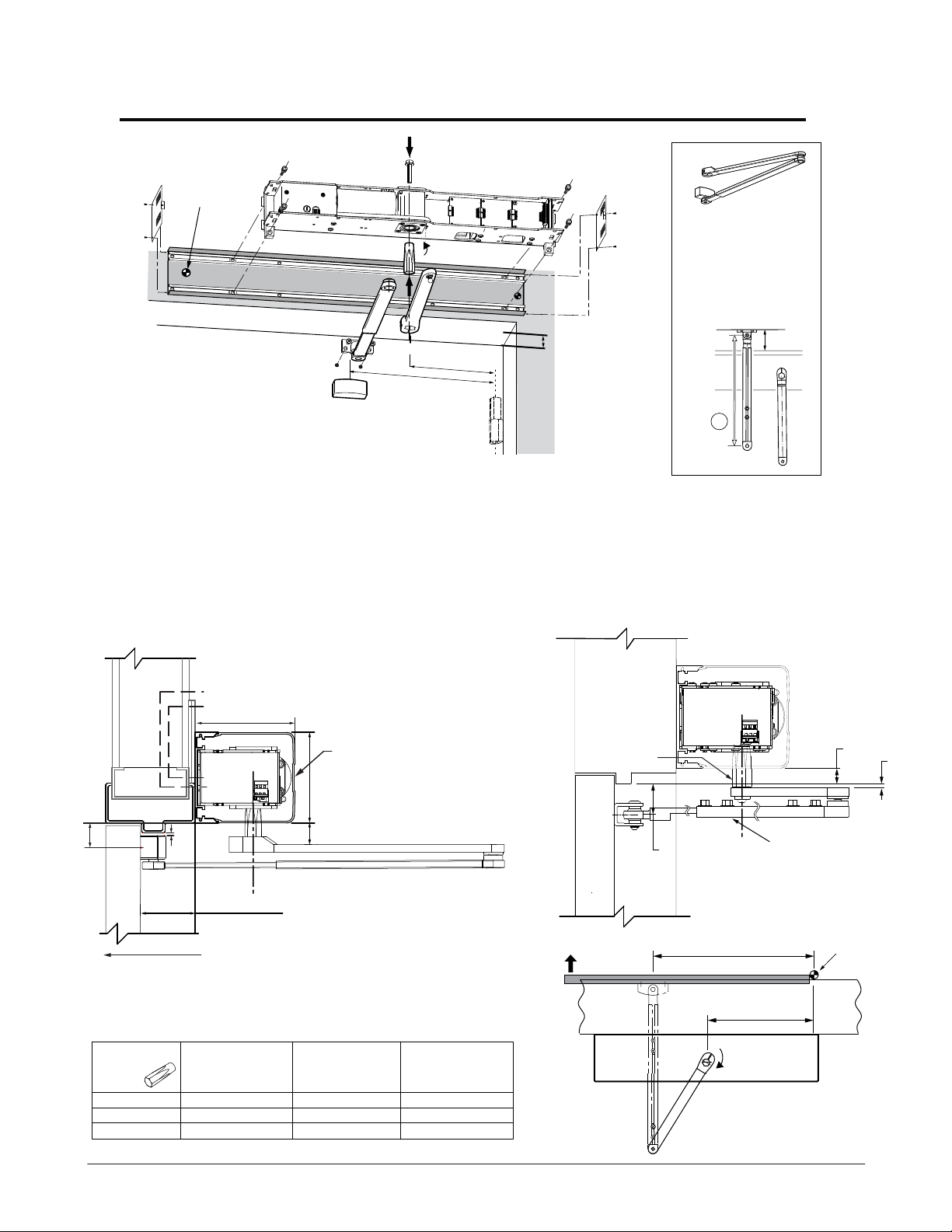
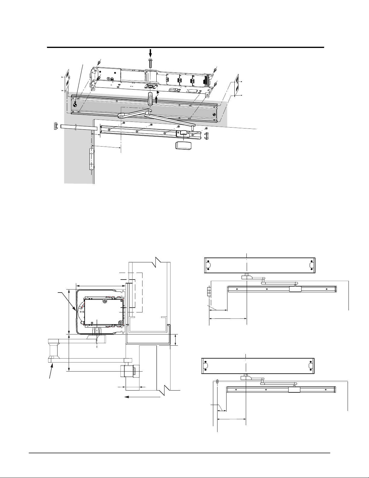
Outswing - Low Energy 8 - 10 lbs Spring Holding Force
Preferred
Primary
Power
1 Push Arm P/N: 408368
0 - 4-
11.41 in. (290 mm)
2 Push Arm P/N: 408369
4-
13.77 in. (350 mm)
3/16” Reveal
1/8” - 9-7/8” Reveal
12-
3/16
” [310]
14-
1/4
” [362]
1) Determine the handing of the operator according to
the door. Note that arrow on operator indicates
opening direction of rotation.
2) Locate & mark output shaft location 12-3/16” from
CL of hinge onto door frame
3) Align header at the bottom of the door frame as shown
below.
4) Secure header to the wall with appropriate hardware.
5) For Stainless Steel Arm refer to illustration on page 13
for mounting dimensions.
Standard Aluminum Arm
Electrical
Controls
5" [127]
TORMAX
1102, 1201
OPERATOR
C
L
Access Cover
4 - 9/16" [116]
Mounting Height
Header
backplate
Reveal Dim.
1,2
CL
Hinge
6) Locate and mount door arm attachment bracket to the
door at Y dimension for shaft used and 14-1/4” from CL of
hinge as shown below.
7) Insert shaft/ drive arm (6) into the operator perpendicular to the
door as shown below. Tighten shaft bolt to 25 ft/ lbs.
8) Manually rotate drive arm (8) as shown below 40°-45°, check
connection point of the two arms to determine how much of the
door portion arm (7) may need to be shortened and/ or cut
off to connect the two arms.
9) Proceed to page 12 to perform commissioning.
CL
14-1/4” [362]
12-3/16” [310]
Header
Hinge
Wall
Y
SWING
DOOR
1/8"
[3]
SWING DIRECTION
Reveal distance is
from the face of the
to the rear of the
Operator 0” - 9-7/8”
X
(0 - 251)
X: Clearance required (distance bottom of header to top of arm)
Y: Distance between bottom of header back plate and centerline
of door mounting shoe
Part No.
141032 (STD)
141106 (D.E.)
141205
Shaft Length
3-
7/32” (82mm)
15/16” (100mm)
34-
27/32” (123mm)
X
1/16” (27mm)
11-25/32” (45mm)
2-
11/16” (68mm)
Y
12-5/32” (55mm)
3-
For extended reveals contact TORMAX
7/16” (36mm)
1/16” (78mm)
7
Rotate Drive Arm
(8) 40° - 45°
NOTE: The door portion arm may need to
be shortened and/ or cut off to
connect the two arms.
Tighten shaft bolt
6
on top of operator
to 25 ft/lbs.
8
11
Outswing - Low Energy 8 - 10 lbs Commissioning
Requirements
1. Shaft should be secured into drive unit during mechanical installation.
2. Refer to page 22 to adjust open door stop.
3. Determine system values for your application based on the illustrations on page 10.
Commissioning
Commissioning Example: (3) = 36” door width, (1) = 0-2” reveal, (1) = Standard outswing Arm 11 3/8.
Press & Hold Programming Button, Release after 1 Green LED Flash. The operator will make 1 beep and immediately
begin to flash the Yellow LED.
WHILE LOOKING AT THE YELLOW LED, WAIT FOR THE OPERATOR TO BEEP 1X, then after 3 yellow flashes, Press & Release
Programming Button
WHILE LOOKING AT THE YELLOW LED, WAIT FOR THE OPERATOR TO BEEP 2X, then after 1 yellow flashes, Press & Release
Programming Button
PAUSE
PAUSE
PAUSE
WHILE LOOKING AT THE YELLOW LED, WAIT FOR THE OPERATOR TO BEEP 3X, then after 1 yellow flashes, Press & Release
Programming Button
MADE AN ERROR DON’T WORRY: To start over Disconnect Power for 10 seconds, Reconnect Power, then Press & Hold
Programming Button and Release after 5 Green LED Flashes.
3 1 1
The operator will open 20 degrees stop and beep 2x. Press & Release programming button.
The operator will slowly close and beep 2x, next it will slowly fully open and beep 2x, then close
(beep 1x) followed by 5 beeps, and will cycle fully open & close at normal speed.
Enter Country Code 7 1: (Read Enre Step BEFORE aempng to enter Country Code)
PERFORM
THIS STEP WHILE LOOKING AT BOTH GREEN & YELLOW LEDS.
Press & Hold programming buon, Release aer 7 Green flashes then immediately Press & Release
programming buon aer 1 Yellow flash.
Programming is complete - for further programming enhancements refer to page 23 or Programming Tables
12
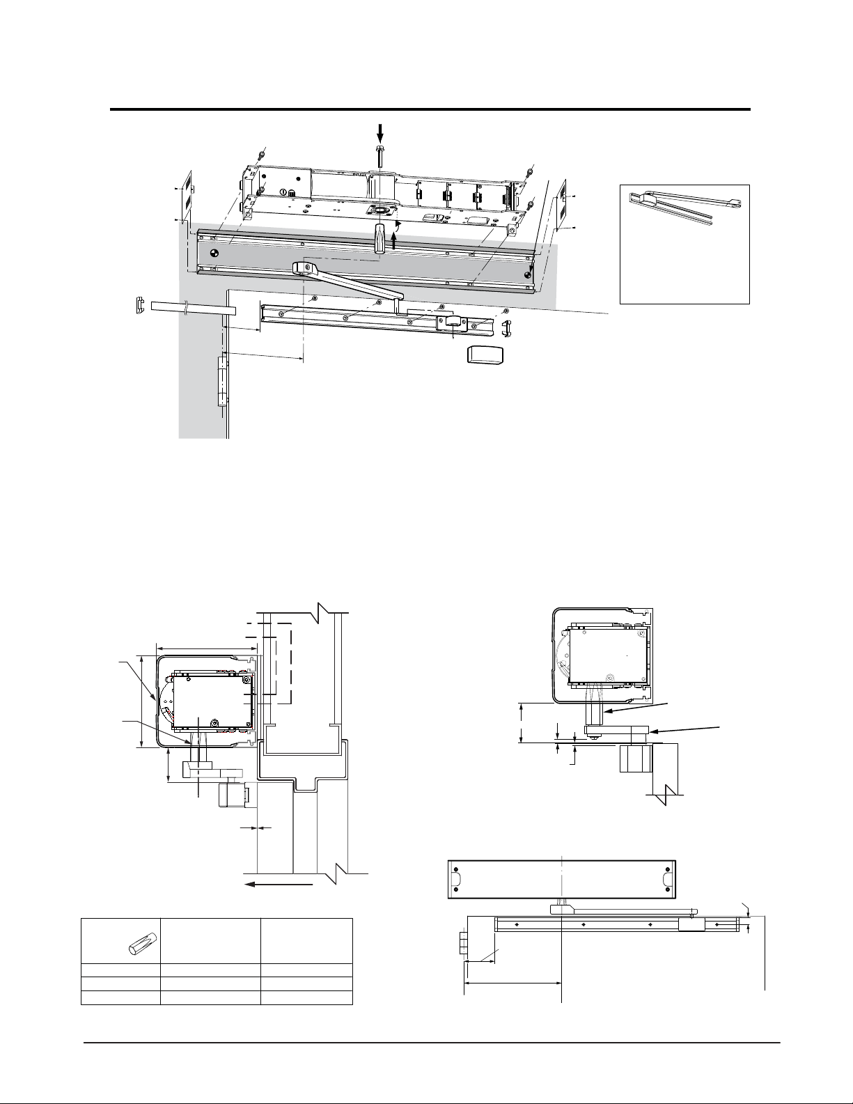
Outswing Full Pedestrian 18 - 20 lbs Spring Holding Force
Preferred
Primary
Power
1 Push Arm P/N: 408368
0 - 4-
11.41 in. (290 mm)
2 Push Arm P/N: 408369
4-
13.77 in. (350 mm)
3/16” Reveal
1/8” - 9-7/8” Reveal
16-
1) Determine the handing of the operator according to
the door. Note that arrow on operator indicates
opening direction of rotation.
2) Locate & mark output shaft location 12-3/16” from
CL of hinge onto door frame
3) Align header at the bottom of the door frame and CL
of the shaft location as shown below.
4) Secure header to the wall with appropriate hardware.
Standard Aluminum Arm
Electrical
Controls
5" [127]
TORMAX
1102, 1201
OPERATOR
C
L
Access Cover
4 - 9/16" [116]
1/8
12-
” [410]
3/16
” [310]
Mounting Height
Header
backplate
Reveal Dim.
1,2
CL
Hinge
5) Locate and mount door arm attachment bracket to the
door at Y dimension for shaft used and 16-1/8” from CL of
hinge as shown below.
6) Insert shaft/ drive arm into the operator, leave shaft bolt loose
until appropriate step during commissioning procedure.
7) Proceed to page 14 to perform commissioning.
Stainless Steel Arm
TORMAX
1102, 1201
C
L
OPERATOR
S.S. Shaft
PT# US801966
11/16" [17]
3/16" [5]
Y
1/8"
SWING
DOOR
SWING DIRECTION
[3]
Reveal distance is
from the face of the
to the rear of the
Operator 0” - 9-7/8”
(0 - 251)
X
X: Clearance required (distance bottom of header to top of arm)
Y: Distance between bottom of header back plate and centerline of door
mounting shoe
Part No.
141032 (STD)
141106 (D.E.)
141205
Shaft Length
3-
7/32” (82mm)
15/16” (100mm)
34-
27/32” (123mm)
X
1/16” (27mm)
11-
25/32” (45mm)
2-
11/16” (68mm)
Y
7/16” (36mm)
12-
5/32” (55mm)
3-
1/16” (78mm)
For extended reveals contact TORMAX
SWING
DOOR
1-3/8" [35]
16-1/8” [410]
12-3/16” [310]
S.S. 0 - 4-3/16” Reveal
Outswing Arm PT# US801983
CL
Hinge
Wall
Header
13
Outswing Full Pedestrian 18 - 20 lbs Commissioning
Requirements
1. Shaft should be loose in the drive unit. Drive arm connected to door and shaft.
2. Determine system values for your application based on the illustrations on page 10.
Commissioning
Commissioning Example: (3) = 36” door width, (1) = 0-2” reveal, (1) = Standard outswing Arm 11 3/8.
Press & Hold Programming Button, Release after 1 Green LED Flash. The operator will make 1 beep and immediately
begin to flash the Yellow LED.
WHILE LOOKING AT THE YELLOW LED, WAIT FOR THE OPERATOR TO BEEP 1X, then after 3 yellow flashes, Press & Release
Programming Button
WHILE LOOKING AT THE YELLOW LED, WAIT FOR THE OPERATOR TO BEEP 2X, then after 1 yellow flashes, Press & Release
Programming Button
PAUSE
PAUSE
PAUSE
WHILE LOOKING AT THE YELLOW LED, WAIT FOR THE OPERATOR TO BEEP 3X, then after 1 yellow flashes, Press & Release
Programming Button
MADE AN ERROR DON’T WORRY: To start over Disconnect Power for 10 seconds, Reconnect Power, then Press & Hold
Programming Button and Release after 5 Green LED Flashes.
3 1 1
The operator will open 20 degrees stop and beep 2x. Attach Door Arm to Shaft and Door, place the Door in the
Closed Position, and
adjust open door stop to desired position, refer to page 22 for adjusting internal Open Door Stop.
RECONNECT POWER (operator beeps 1x), then Press & Hold programming button & Release after 6 Green LED
Flashes. The operator will open 20 degrees stop and beep 2x.
slowly close and beep 2x, next slowly fully open & beep 2x, then close (beep 1x) followed by 5 beeps, and will cycle
fully open & close at normal speed.
NOW Tighten the shaft to the operator at 25 ft-lbs. REMOVE POWER from Operator and
Press & Release programming button. Operator will
Commissioning is complete for High Energy Applications. For Low Energy application complete the last step below
Program the country code into the controller. For additional programming refer to page 23 or Programming Tables.
Enter Country Code 7 1: (Read Entire Step BEFORE attempting to enter Country Code)
PERFORM THIS STEP WHILE LOOKING AT BOTH GREEN & YELLOW LEDS.
Press & Hold
programming button after 1 Yellow flash.
programming button, Release after 7 Green flashes then immediately Press & Release
14
Inswing (Pull) Arm 0” Reveal Installation
Preferred
Primary
Power
4”[102mm]
12-
3/16
”
[310mm]
1) Determine the handing of the operator according to
the door. Note that arrow on operator indicates
opening direction of rotation.
2) Locate & mark output shaft location 12-3/16” from
CL of hinge onto door frame as
3) Determine header mounting height = X. See below.
4) Bolt header to the wall with appropriate hardware.
Standard Aluminum Arm
Electrical
C
L
Controls
TORMAX
1102, 1201
OPERATOR
ACCESS
COVER
4 9/16" [116]
Standard
Shaft 141032
3-7/32” (82mm)
5" [127]
X
Standard Inswing Arm
0” Reveal, P/N 407456
13.77 in. (350 mm
1) )
5) Locate and mount door arm slide track onto the door at
4” from C/L of pivot, mounting holes 5/8” from top of the
door as shown below.
6) Insert shaft/ drive arm into the operator, leave shaft bolt
loose until appropriate step during commissioning
procedure.
7) Proceed to page 16 to perform commissioning.
Stainless Steel Arm
TORMAX
1102, 1201
OPERATOR
S.S. Shaft
PT# US801966
3/16” [5]
1-7/8” [48]
1/8” [3]
Top of
the Door
S.S. 0” Reveal
Inswing Arm
PT# US801996
SWING
0” Reveal
Door Arm
407456
X: Mounting height (distance bottom of header to top of door)
Part No.
141032 (STD)
141205
141020
Shaft Length
3-
7/32” [82mm]
27/32” [123mm]
42-
5/8” [67mm]
DOOR
SWING DIRECTION
X
3/4”” (44mm]
13-
3/8” [86mm]
1-
5/32” [29mm]
For extended reveals contact TORMAX
C/L
Pivot
Header
4”
[102]
12-3/16” [310]
Butt Hingle or Offset Pivot
5/8” [16]
C/L
Shaft
15
Inswing (Pull) Arm 0” Reveal Commissioning
Requirements
1. Shaft should be loose in the drive unit. Drive arm connected to slide track and shaft.
2. Determine system values for your application based on the illustrations on page 10.
Commissioning
Commissioning Example: (3) = 36” door width, (1) = 0-2” reveal, (1) = Standard inswing Arm 11 3/8.
A
Press & Hold Programming Button, Release after 1 Green LED Flash. The operator will make 1 beep and immediately
begin to flash the Yellow LED.
WHILE LOOKING AT THE YELLOW LED, WAIT FOR THE OPERATOR TO BEEP 1X, then after 3 yellow flashes, Press & Release
Programming Button
WHILE LOOKING AT THE YELLOW LED, WAIT FOR THE OPERATOR TO BEEP 2X, then after 1 yellow flashes, Press & Release
Programming Button
PAUSE
PAUSE
PAUSE
WHILE LOOKING AT THE YELLOW LED, WAIT FOR THE OPERATOR TO BEEP 3X, then after 4 yellow flashes, Press & Release
Programming Button
MADE AN ERROR DON’T WORRY: To start over Disconnect Power for 10 seconds, Reconnect Power, then Press & Hold
Programming Button and Release after 5 Green LED Flashes.
3 1 4
The operator will open 20 degrees stop and beep 2x. Attach Door Arm to Slide Track and Shaft, place the Door in the
Closed Position, and
adjust open door stop to desired position, refer to page 22 for adjusting internal Open Door Stop.
RECONNECT POWER (operator beeps 1x), then Press & Hold programming button & Release after 6 Green LED
Flashes. The operator will open 20 degrees stop and beep 2x.
slowly close and beep 2x, next slowly fully open & beep 2x, then close (beep 1x) followed by 5 beeps, and will cycle
fully open & close at normal speed.
NOW Tighten the shaft to the operator at 25 ft-lbs. REMOVE POWER from Operator and
Press & Release programming button. Operator will
Commissioning is complete for High Energy Applications. For Low Energy application complete the last step below
Program the country code into the controller. For additional programming refer to page 23 or Programming Tables.
Enter Country Code 7 1: (Read Entire Step BEFORE attempting to enter Country Code)
PERFORM THIS STEP WHILE LOOKING AT BOTH GREEN & YELLOW LEDS.
Press & Hold
programming button after 1 Yellow flash.
programming button, Release after 7 Green flashes then immediately Press & Release
16
Inswing (Pull) Arm 0 - 6” Reveal Installation
Primary
Power
See details below
1) Determine the handing of the operator according
to the door. Note that arrow on operator indicates
opening direction of rotation.
2) Locate & mark output shaft location as shown
below from CL of hinge or pivot onto door frame.
3) Mark header mounting height of 1 1/8” from the top
of the door as shown below.
4) Secure header to the wall with appropriate hardware.
Electrical
Controls
5" [127]
Access
Cover
TORMAX
4 9/16" [116]
3 3/4” [95]
1102, 1201
OPERATOR
C
L
SWING
DOOR
5) Locate and mount door arm slide track onto the door at 3 3/4”
from bottom of the header and at the dimensions listed below
for the application.
6) Insert shaft/ drive arm into the operator, leave shaft bolt loose
until appropriate step during commissioning procedure.
7) Proceed to page 18 to perform commissioning.
Butt Hinge
Header
2-1/4”
[57]
10-5/8” [270]
C/L
Pivot
1 1/8" [28]
C/L
Shaft
Center Pivot
0 - 6”” Reveal Door Arm
141133 R.H.Shown
141134 L.H.Not Shown
REVEAL DISTANCE
FROM THE FACE OF
THE DOOR TO THE
REAR OF OPERATOR
0"-6" (0-152)
SWING DIRECTION
1-1/4”
[32]
9-7/16”[240]
C/L
Pivot
Header
C/L
Shaft
17
Inswing (Pull) Arm 0 - 6” Reveal Commissioning
Requirements
1. Shaft should be loose in the drive unit. Drive arm connected to door and shaft.
2. Determine system values for your application based on the illustrations on page 10.
Commissioning
Commissioning Example: (3) = 36” door width, (1) = 2-4” reveal, (1) = Extended inswing Arm B.
B
Press & Hold Programming Button, Release after 1 Green LED Flash. The operator will make 1 beep and immediately
begin to flash the Yellow LED.
WHILE LOOKING AT THE YELLOW LED, WAIT FOR THE OPERATOR TO BEEP 1X, then after 3 yellow flashes, Press & Release
Programming Button
WHILE LOOKING AT THE YELLOW LED, WAIT FOR THE OPERATOR TO BEEP 2X, then after 2 yellow flashes, Press & Release
Programming Button
PAUSE
PAUSE
PAUSE
WHILE LOOKING AT THE YELLOW LED, WAIT FOR THE OPERATOR TO BEEP 3X, then after 6 yellow flashes, Press & Release
Programming Button
MADE AN ERROR DON’T WORRY: To start over Disconnect Power for 10 seconds, Reconnect Power, then Press & Hold
Programming Button and Release after 5 Green LED Flashes.
3 2 6
The operator will open 20 degrees stop and beep 2x. Attach Door Arm to Slide Track and Shaft, place the Door in the
Closed Position, and
adjust open door stop to desired position, refer to page 22 for adjusting internal Open Door Stop.
RECONNECT POWER (operator beeps 1x), then Press & Hold programming button & Release after 6 Green LED
Flashes. The operator will open 20 degrees stop and beep 2x.
slowly close and beep 2x, next slowly fully open & beep 2x, then close (beep 1x) followed by 5 beeps, and will cycle
fully open & close at normal speed.
NOW Tighten the shaft to the operator at 25 ft-lbs. REMOVE POWER from Operator and
Press & Release programming button. Operator will
Commissioning is complete for High Energy Applications. For Low Energy application complete the last step below
Program the country code into the controller. For additional programming refer to page 23 or Programming Tables.
Enter Country Code 7 1: (Read Entire Step BEFORE attempting to enter Country Code)
PERFORM THIS STEP WHILE LOOKING AT BOTH GREEN & YELLOW LEDS.
Press & Hold
programming button after 1 Yellow flash.
programming button, Release after 7 Green flashes then immediately Press & Release
18
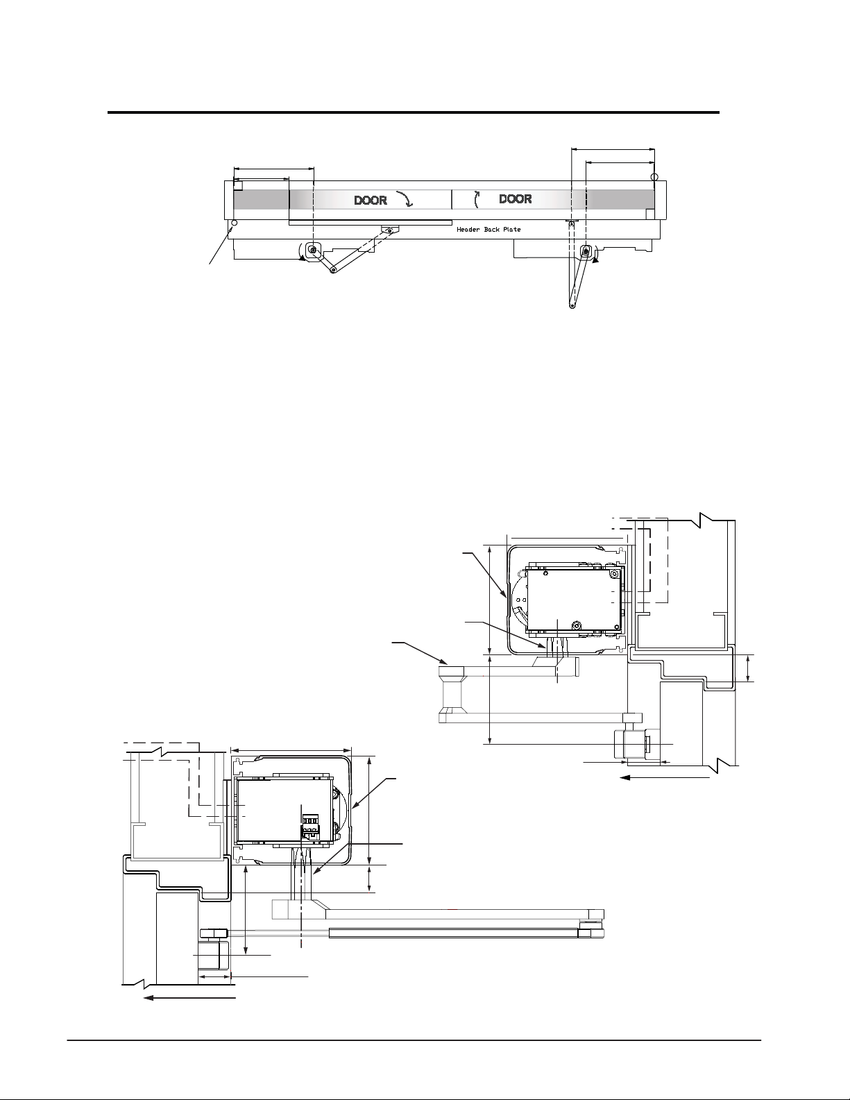
Double Egress Application Installation
”8/50
10 5/8” [270]
”4/12
Butt Hung & Offset Pivot
C/L of
Pivot
1) Determine the handing of the operators according to
the door. Note that arrow on operator indicates
opening direction of rotation.
2) Locate & mark output shaft locations as shown above,
for both operators.
3) Determine header mounting height. If both operators are
in a single header then mount the operators at 1-1/8”
from top of the door as shown below for In-Swing operator.
0 - 6”” Reveal Door Arm
141133 R.H.Shown
141134 L.H.Not Shown
Shaft 141032
16 1/8” [410]
12 3/16” [310]
4) Secure header to the wall with appropriate hardware.
5) Locate and mount door arm and slide track onto the
doors at dimensions listed above.
6) Insert shaft/ drive arms into the operators, leave shaft
bolts loose until appropriate step during commisioning
procedure.
7) Proceed to page 20 to check or connect sync cable and
additional wiring.
In-Swing Operator
Electrical
Controls
TORMAX
1102, 1201
OPERATOR
C
C
L
L
Access
Cover
4 9/16" [116]
Standard
3 7/32” (82)
5" [127]
1 1/8" [29]
Electrical
Controls
Out-Swing Operator
5" [127]
TORMAX
1102, 1201
OPERATOR
SWING
DOOR
SWING DIRECTION
3 9/16" [90]
C
L
REVEAL DISTANCE FROM THE
FACE OF THE DOOR TO THE
REAR OF OPERATOR
0"-9 7/8" (0-251)
4 9/16" [116]
1 1/8" [29]
Access
Cover
Standard D.E. Shaft 141106
3 15/16” (100mm)
3 3/4” [95]
REVEAL DISTANCE
FROM THE FACE OF
THE DOOR TO THE
REAR OF OPERATOR
0"-6" (0-152)
SWING
DOOR
SWING DIRECTION
19
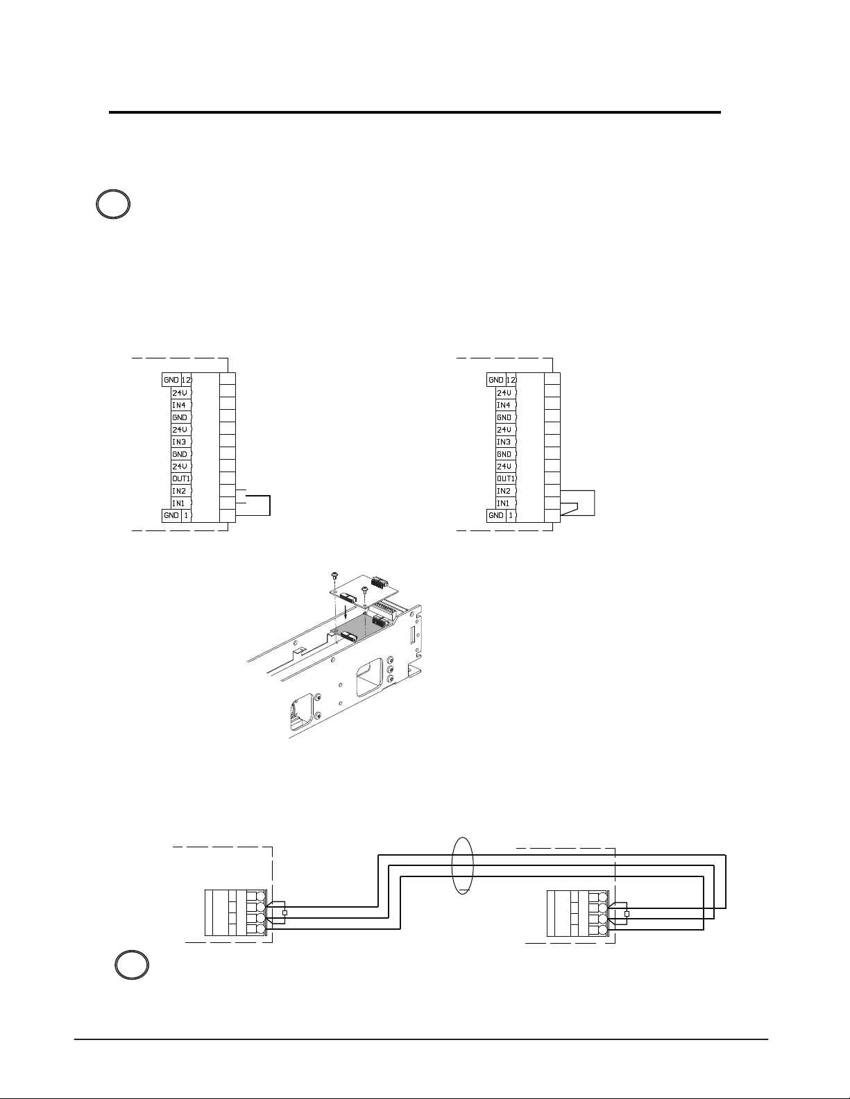
Pair & Double Egress Application Wiring
1. Determine which operator will be the primary drive as this will have the 3-position
switch connection.
The FCP is an option in place of the 3-position and will be connected to the primary
drive with appropriate module, Exterior Door module EDM or Programming Interface
!
module PIM.
2. Check and/ or install jumpers between GND pin 1 - IN1 pin 2 and GND pin 1 - IN2 Pin 3
in place of the 3-position switch on the secondary drive as shown below.
Primary Drive Secondary Drive
Base Door Module BDM Base Door Module BDM
A
12
11
10
9
8
7
6
5
4
OPEN
3
2
1
3-pos.-switchOFF
A
12
11
10
9
8
7
6
5
4
3
2
1
Double door configuration
Recognition as
secondary drive
3. Install Multi Door Module MDM-B into each operator.
T1638_4
4. Connect Sync cable (US801886) to both drives Multi Door Module MDM - B as shown below.
Wiring of Sync Cable
Primary Drive
Multi Door Module MDM-B
A
4
24V
H
3
GND
2
L
1
120 Ω
Red
Green
Black
SYNC
CABLE
Secondary Drive
Multi Door Module MDM-B
A
4
24V
H
3
GND
2
L
1
120 Ω
Red
Green
Black
Do not apply primary power to the drive units until the appropriate step.
!
Proceed to page 21.
20
 Loading...