

®
Installation and Service Manual
1102/ TTX Swing Door Operator
TORMAX 1201 Swing Door Operator
Warning -
TORMAX USA Inc.
12859 Wetmore Road
San Antonio,TX 78247
210-494-3551
210-494-5930 (FAX)
888-685-3707
www.tormaxusa.com
info@tormaxusa.com
To reduce the risk of injury of persons - Use this operator only with swing doors.
Issue Date: 05/04/2018
P/N : US801918
Version: FW_3.11

TABLE OF CONTENTS
SECTION
Table of Contents
Important Information
Safety Warnings, Installation & Service, Glazing
Intended Installation Environment, Door Operation, ANSI/ BHMA
Operator Applications, Country Code, User mode with FCP
1. Modes of Door Operation
2. Components Overview
3. Applications
4. On-Board Programming Configuration Tool - Description
5. System Values for Application
Installation
6. Applications: Outswing 8-10 lbs. Spring Force Installation/ Commissioning
Outswing 18-20 lbs. Spring Force Installation/ Commissioning
Inswing 0” Reveal Installation/ Commissioning
Inswing 0”-6” Reveal Installation/ Commissioning
Double Egress Application Installation
Pair/ Double Egress Application Wiring
Pair/ Double Egress Application Commissioning
7. Adjustments:
1102/ 1201 Open Door Stop, 1201 Spring Tension
Frequently Used
8. Slim Line Header
Header Preparation
Application Illustrations
9. Programming with the FCP - Overview, Example
10. Commissioning with FCP
Commissioning, Adjustments
On-Board Codes 3, 6, 7 Descriptions/ BDM LED Display
11. Programming & Trouble Shooting Tables
12 Control Connection Diagram
13. Wiring Diagrams
Single Applications
Pair / Double Egress Applications
14. Technical Specifications:
Shaft Removal
T1253 Cable Plan
T1633 1201 Technical Information
T1634 1102 Technical Information
Electrical Requirements for Installation
T1753 Double Door Application
T1637 Basic Door Module (BDM) MCU42-BDM-A
T1638 Exterior Door Module (EDM) MCU42-EDM-A
T1640 Multi-Door Module (MDM) MCU42-MDM-A /B
T1639 Power Door Module (PDM) MCU42-PDM-A
T1691 Programming Interface Module (PIM) MCU42-PIM-A
T1757 Functional Control Panel (FCP) MCU32USIN-7-A
PAGE
2
3
4
5
6
7
8
9
10
11 - 12
13 - 14
15 - 16
17 - 18
19
20
21
22
23
24
25
26 - 28
29 - 30
31
32 - 36
37
38 - 42
43 - 47
48
49
50
51
52
53 - 54
55 - 56
57 - 58
59 - 60
61 - 62
63
64 - 65
2
Important Information
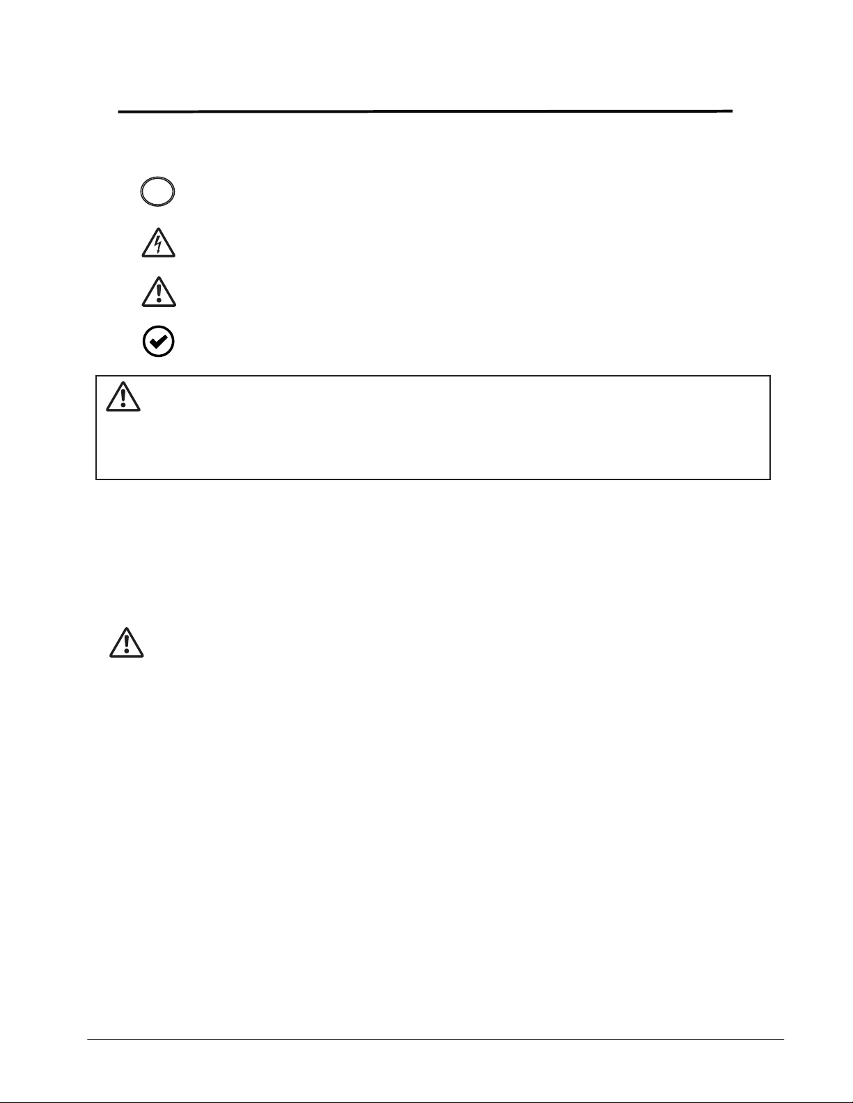
SAFETY/ WARNINGS SYMBOLS
NOTE indicates important information specific to the process or steps
!
being performed.
ELECTRICAL VOLTAGE indicates that electrical voltage is present
and that caution should be taken to prevent injury or property damage.
CAUTION indicates failure to follow instructions may result in personal
injury and/ or property damage.
OPTIONAL COMPONENTS indicates components that are not installed
in all systems.
WARNING - Failure to observe the information in this manual may result in
personal Injury or damage to equipment. To reduce the risk of
injury of persons use this operator only with pedestrian swing
doors.
Save these instructions for future reference.
Installation and Service
Any and all TORMAX equipment must be installed, serviced and inspected by an AAADM
Certified technician, to meet the current ANSI A156.10 and/ or ANSI A156.19 standard
and any local or state building codes.
The person responsible for the daily operation and maintenance of the system is referred to as
“End-User”.
It is the technicians responsibility:
1. Review the functions of the equipment with the end-user. Failure to do so, may lead to
the improper use, could cause injury to persons and/ or damage to the equipment.
2. Familiarize the end-user with the Daily Safety Check Decal and how to perform the
walk test procedures.
3. Illustrate to the end-user how to place the door out of service (turn off power or place
in P mode or OFF mode of operation), if the equipment does not perform as described
in the Daily Safety Check Decal.
4. Recommend to the end-user to have their equipment inspected annually by an
AAADM certified technician.
Glazing
The glazing material of all doors shall comply with the requirements of ANSI Z97.1, American
National Standard Performance Specifications and Methods of Test for Safety Glazing Material
Used in Buildings.
3

Important Information
Intended Installation Environment
The 1102/ TTX and the 1201 are non-handed swing door operators that can be used on
interior or exterior doors.
The operator is mounted above the door on the inside of the building. Any other use, or any
use exceeding this aim, is deemed as not used in accordance with its intended purpose.
The manufacturer will not be liable for damages resulting from such applications or warranty the
product. Arbitrary changes to the system will exempt the manufacturer from any liability for
damage resulting from this.
The 1102/ TTX is designed as a Low Energy operator to comply with ANSI A156.19
standard.
The 1201 can be utilized as a Low Energy operator and comply with ANSI A156.19
standard, or setup to operate as a Power Operated Pedestrian Door and comply with
ANSI A156.10 standard.
Upon completion of the installation the technician should perform an AAADM inspection to
ensure that the door complies to the appropriate standard ANSI a156.19 or ANSI A156.10
in which it is setup to operate within.
Door Operation
The 1102/ 1201 mode of operation is control by a 3-position switch (standard) or a (FCP)
Functional Control Panel (optional). The primary mode of operations are:
Off - The door remains in the closed position with lock engaged, but can
be opened by the Key Switch activating input.
Automatic - Two-way traffic, typical setting for normal operation. Allows the interior &
exterior sensors, Key switch and safety devices (if applicable) to operate
the door.
Hold Open - The door goes to the open position and remains there until the switch is taken
out of this position.
Upon a power loss the operation of the 1102/ 1201 operating system will function according to
specifications:
Immediate spring closing.
The operator functions as a manual door closure.
Lock function will operate to specification (fail secure/ fail safe).
Continued operation , if equipped with a battery backup.
ANSI/ BHMA A156.10, A156.19 standards - Knowing Act Switch
Doors activated by a manual switch must have the switch installed in a location
from which the operation of the door can be observed by the person operating
the switch. Refer to the latest revision of ANSI/ BHMA A156.10 or A156.19 for
location of Knowing Act switch and time delays.
4

Important Information
Operator Applications
The 1102/ 1201 are Surface Applied (SA) operators and are power open and spring close.
Basic configuration adjustments will be made with an on-board programming button.
The operator has 2 standard applications:
Outswing - The operator pushes the door open.
Inswing - The operator pulls the door open.
Within each standard application there are important points to know and consider during
the installation process.
Outswing: 8-10 lbs. of manual opening force (Low Energy ANSI A156.19) or Knowing
Act Door Activation (Power Operated Pedestrian Door ANSI A156.10)
18-20 lbs. of manual opening force ( Power Operated Pedestrian Door
ANSI A156.10)
InSwing: 0” reveal, non-handed arm
0“ - 6” reveal, handed arm
Country Code
The Country code is available in firmware V3.02 and above. The country code provides preset
values to aid the technician in installing the door to comply with ANSI Standard A156.19.
This does not eliminate the need for an AAADM inspection to be performed for compliance.
Additional adjustments may need to be made upon inspection.
“U” User mode on FCP
The User mode has two options:
UR - Ability to read specific programming parameters without changing the parameter.
UP - Ability to change programming parameters within a limited range.
Refer to programming table for specifics.
Recommend using “P” programming mode to have full range of adjustments on all parameters.
!
5
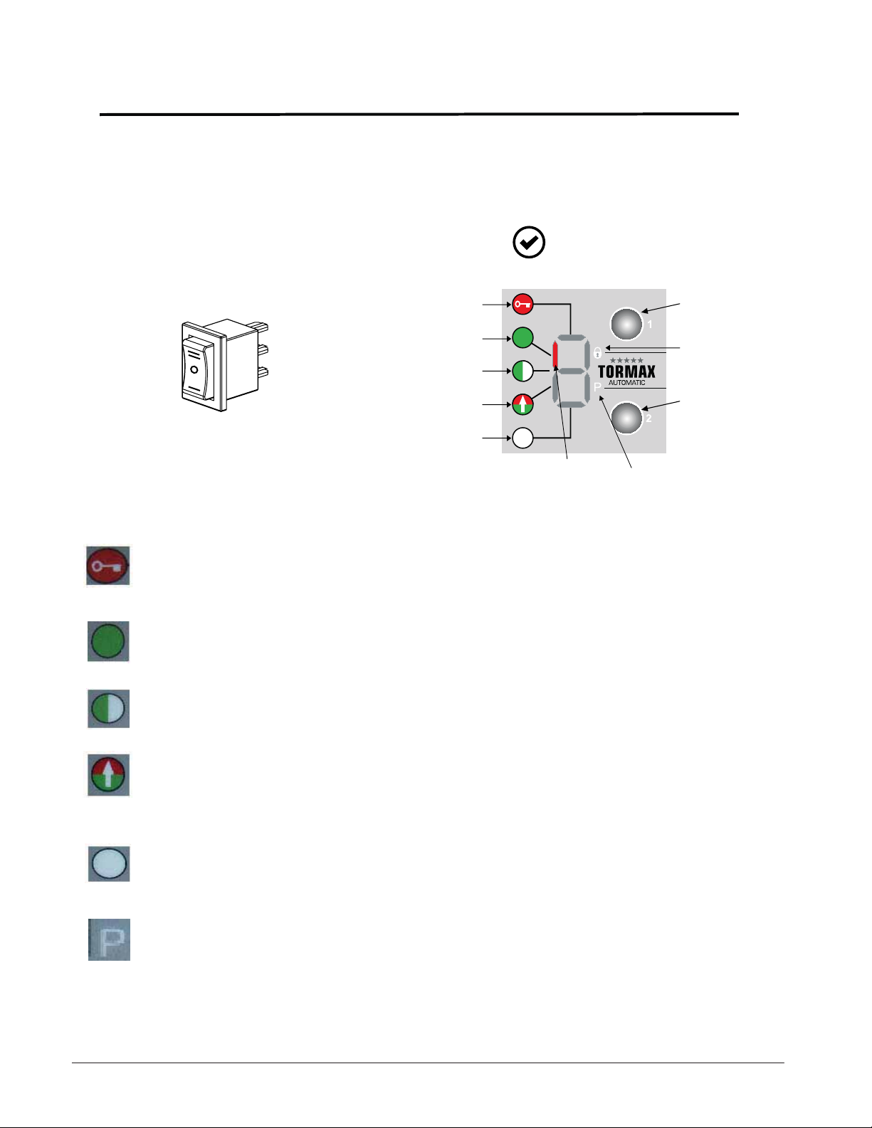
Modes of Door Operation
Modes of operation can be selected with either the standard 3-position switch or the
optional 6 position Functional Control Panel (FCP).
The technician will review the appropriate mode switch with the end-user.
HOLD OPEN
AUTO
OFF
1. OFF - The interior and exterior activators are inhibited after the door reached
the fully closed position, if an electric lock is present it will be activated. Door
will cycle open, if a signal is sent to the key switch input.
2. AUTOMATIC - Typical setting for normal 2-way traffic operation with interior
and exterior activators, key switch input and safety devices operating the door.
Standard:
1102/ 1201
#1) OFF Mode
#2) AUTOMATIC Mode
#3) REDUCED OPEN Mode
#4) EXIT Mode
#5) HOLD OPEN Mode
Optional:
1102/ 1201
www.tormaxusa.com
LED indicates current
operating mode
KEY 1
Electric door
lock LED indicator
KEY 2
#6) (P) MANUAL Mode
3. REDUCED OPERATING - Allows the door to open with a reduced opening
width. Activators and safety devices operate the same as automatic mode.
4. EXIT - (1-way traffic) Allows interior activator and key switch inputs to operate
the door. The exterior activator input is inhibited from opening the door while
the door is closed. When the door is opened/ closing the exterior activator
becomes operational and will re-open a closing door.
5. HOLD OPEN - Hold and maintains the door in the open position.
6. (P) MANUAL OPERATION - Allows the door to be used manually without the
use of sensors. Push and pull motion applied to the door to open and close
the door.
6
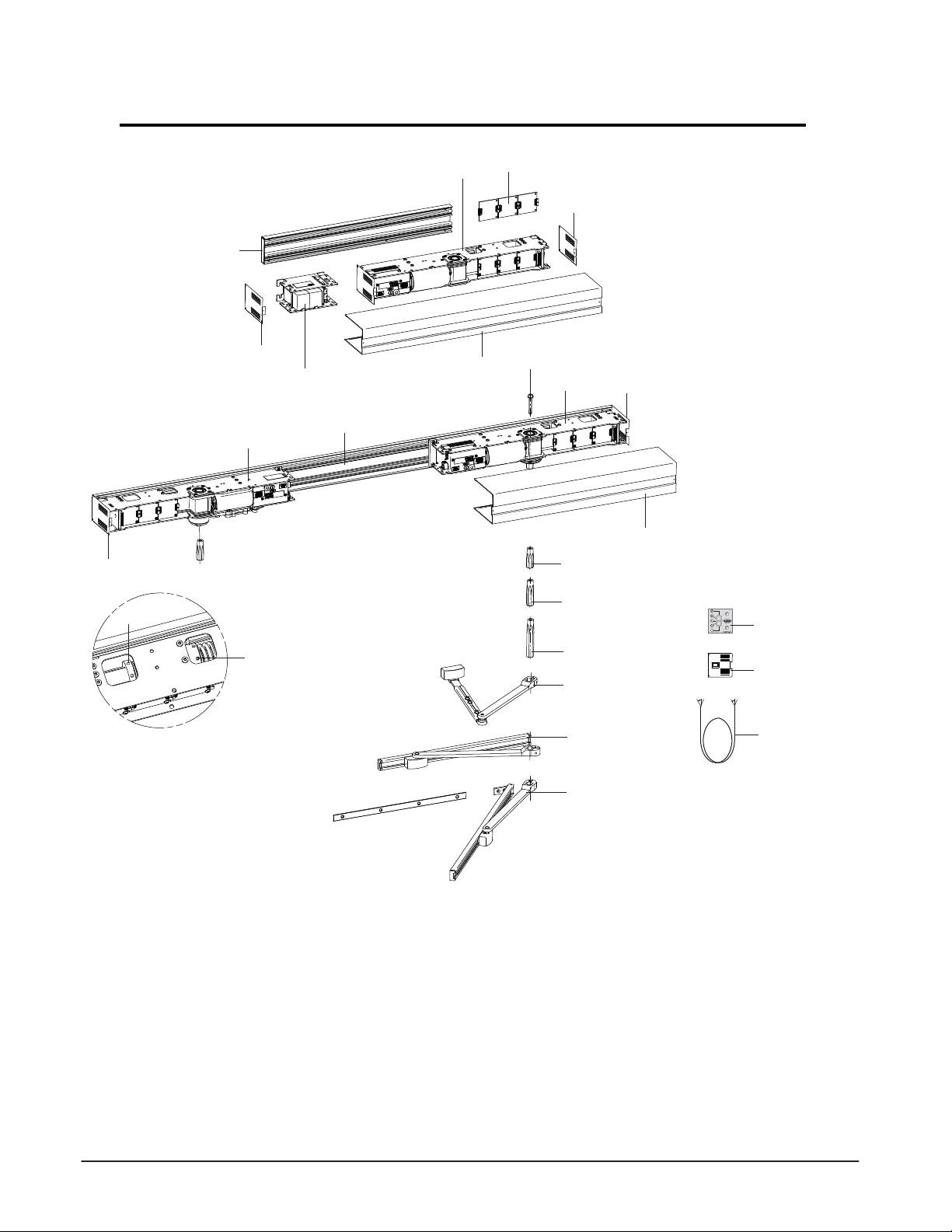
Components Overview
Single Door
15
1
13
Double Door
13
3
14
1
13
11
14
2
4
12
19
1
5
6
7
8
13
12
16
OPEN
AUTO
OFF
17
1 Primary drive TORMAX 1102/1201
2 Secondary drive TORMAX 1102/1201
3 Adjustment of spring force TORMAX 1201 only
4 Adjustment of internal open end stop
5 Shaft 2.48 in. (63 mm)
6 Shaft 3.22 in. (82 mm)
7 Shaft 4.84 in. (123 mm)
8 Out-Swing (Push) Arm 11.41/ 13.77 in. (290/350 mm)
9 In-Swing (Sliding Pull) Arm 13.77/ 19.68 in. (350/500 mm)
10 In-Swing (Slide/ Pull) Arm w/Panic 19.68 in. (350 mm)
(not available at this time)
9
10
11 Battery unit
18
12 Header cover
13 Side plate
14 Mounting profile
15 Upgrade modules MDM, PDM, EDM
16 Functional Control Panel (FCP) User interface (Option)
17 On/Off/Hold Open mode of operation switch (Standard)
18 Sync Cable for pairs
19 Shaft retaining bolt
7
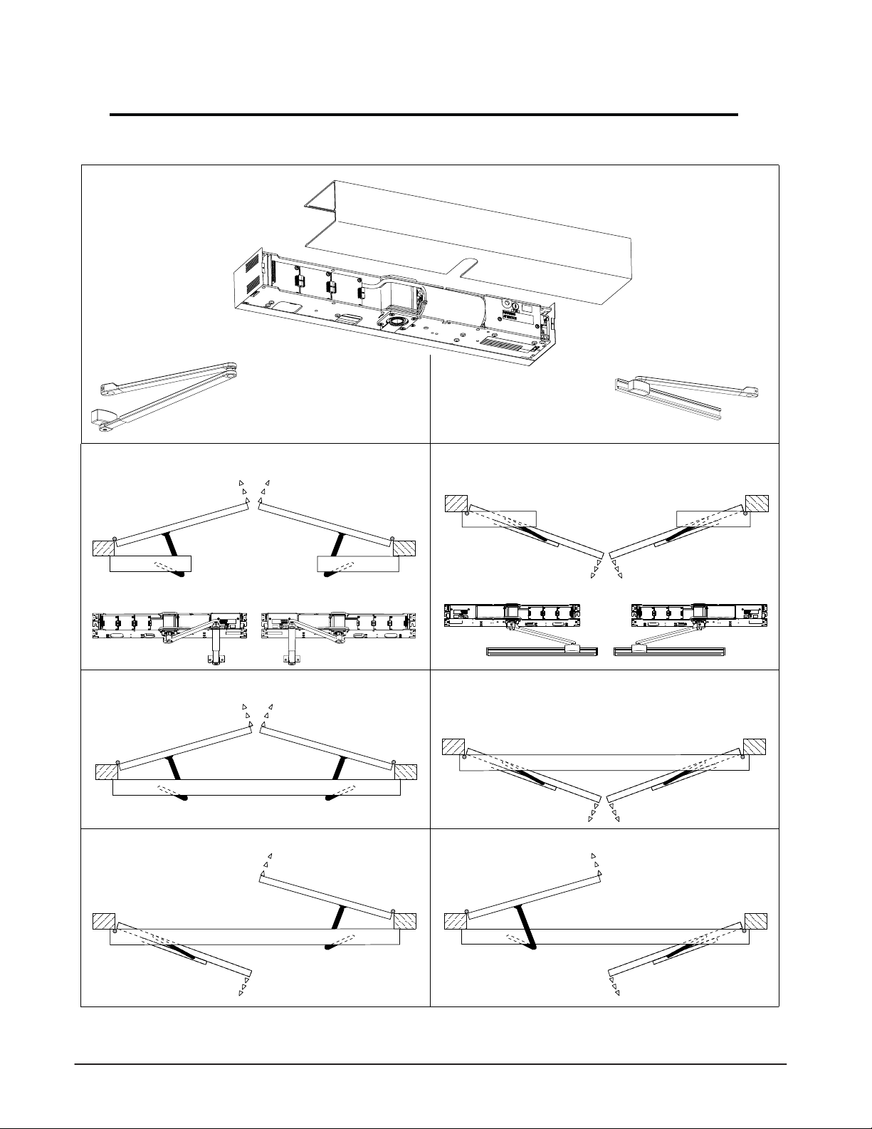
APPLICATIONS
Standard (Out-Swing) Push Arm Singles
Operator Non-handed
LH
Standard (Out-Swing) Push Arm Pair
Operator Non-handed
LH
Standard Double Egress Pair - RH
Operator Non-handed
RH
RH
Standard (In-swing) Pull Slide Arm Singles
Operator Non-handed
RH
Standard (In-Swing) Pull Slide Arm Pair
Operator Non-handed
Standard Double Egress Pair - LH
Operator Non-handed
LH
LHRH
RH
RH
LH
LH
8
On-Board Programming Configuration Tool - Description
Overview
The On-board programming tool allows the installer to commission the operator without the
use of the FCP. If additional changes are needed i.e. time delay, push-n-go the FCP will be
required.
The on-board programming tool utilizes the programming button, green & yellow LEDs and
an audible tone device to aid the installer during the commissioning process. During the
commissioning process, the LED’s flashing sequence and audible tone will continually repeat
until a selection is made, then the audible tone and flashing sequence changes for the next
parameter selection.
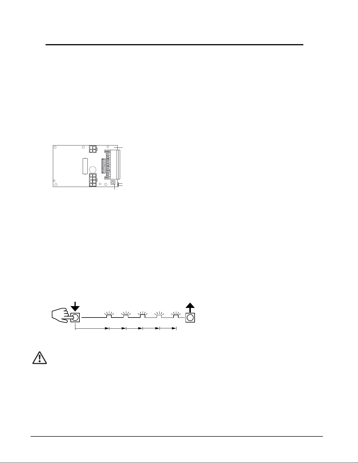
On-board Configuration Tool Familiarization
M
1
A
T1652_1
Programming functions can be launched by means of the programming button.
The GREEN LED supports parameter selection Release the button at the right point in time.
4
3
2
The YELLOW LED indicates the parameter by a series of flashes Press the button at the right point in time.
Programming Procedure – General
• Keep the programming button depressed. The GREEN LED starts to FLASH at one second intervals
for a short time. The number of flashes corresponds to the programming code as in the programming
table.
• Release the programming button after the required number of GREEN FLASHES.
Example: Code 5 “Factory Reset” (see below for codes)
Press Programming button
GREEN LED
3 s 1. 2. 3.
1 Base door module BDM
2 Programming Button
3 LED GREEN: status display (control system ready for operation)
or configuration display.
4 LED YELLOW: error display or configuration display
Release Programming button
This ends the programming step.
5.
4.
Programming Codes
In order to ensure the safety of the system, please follow the details of the programming steps in
the following pages.
Code 1: Commissioning (enter system values, preloads, performs learn)
Code 2: (Consult factory)
Code 3: Detecting/mask out safety features
Code 4: Spring pre-tension parameter (only applicable for TORMAX 1201)
Code 5: Factory reset (Reset all values, excluding operator type)
Code 6: Repeat commissioning (without entering system values, door preloads, performs learn)
Code 7: Preset value 1 = Low Energy (preset values for multiple parameters)
9
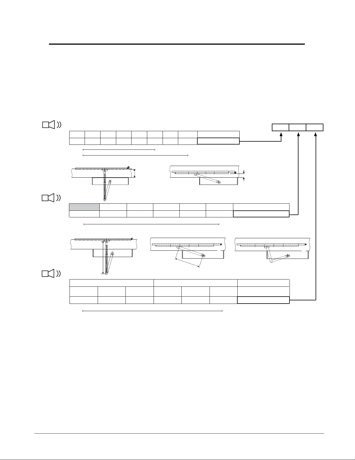
System Values for the Application
System Values
After installing the operator determine the 3 system values. Measure the dimensions
shown in the illustrations below, select each system value listed below the measurement.
Write these numbers down as they are referenced during commissioning.
Audible Tone
Number of Flashes
Audible Tone
Number of Flashes
Audible Tone
Number of Flashes
1
Door width
28” 32” 36” 40” 44” 48”
1 2 3 4 5 6 7 8
1102
1201
2
Reveal
0 - 2” 2 - 4” 4 - 6” 6- 8.5” 8.5 - 10.5” 10.5 - 12.5” Distance A
Yellow LED
Yellow LED
A
*52” *56” Door width
Value 1
Green LED
1 2 3 4 5 6 Value 2
C
3
Drive Arm
Outswing Inswing
11-3/8”
Custom 13-3/4”
A
A
Custom
B
1 2 3 4 5 6 Value 3
Yellow LED
A
Green LEDYellow LED
Lever length C
Green LED
System Values
B
10
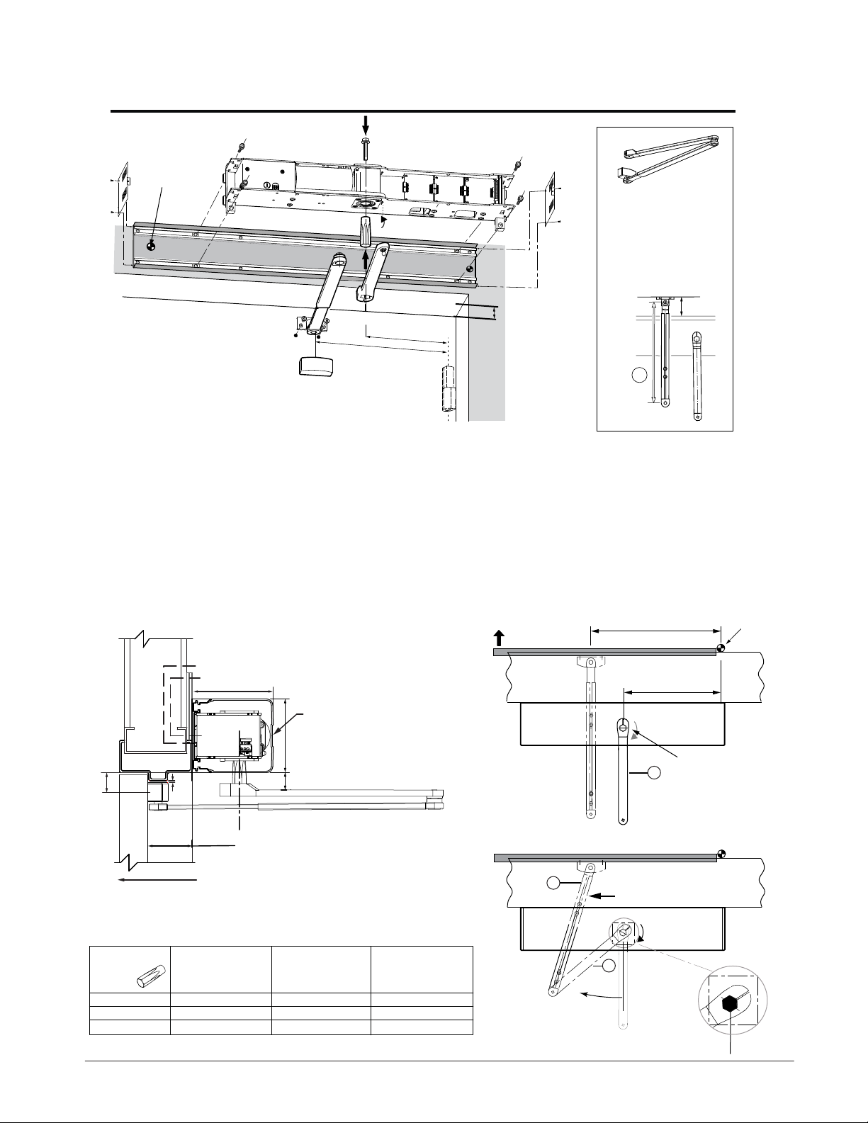
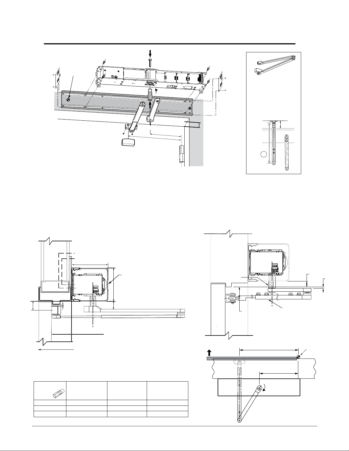
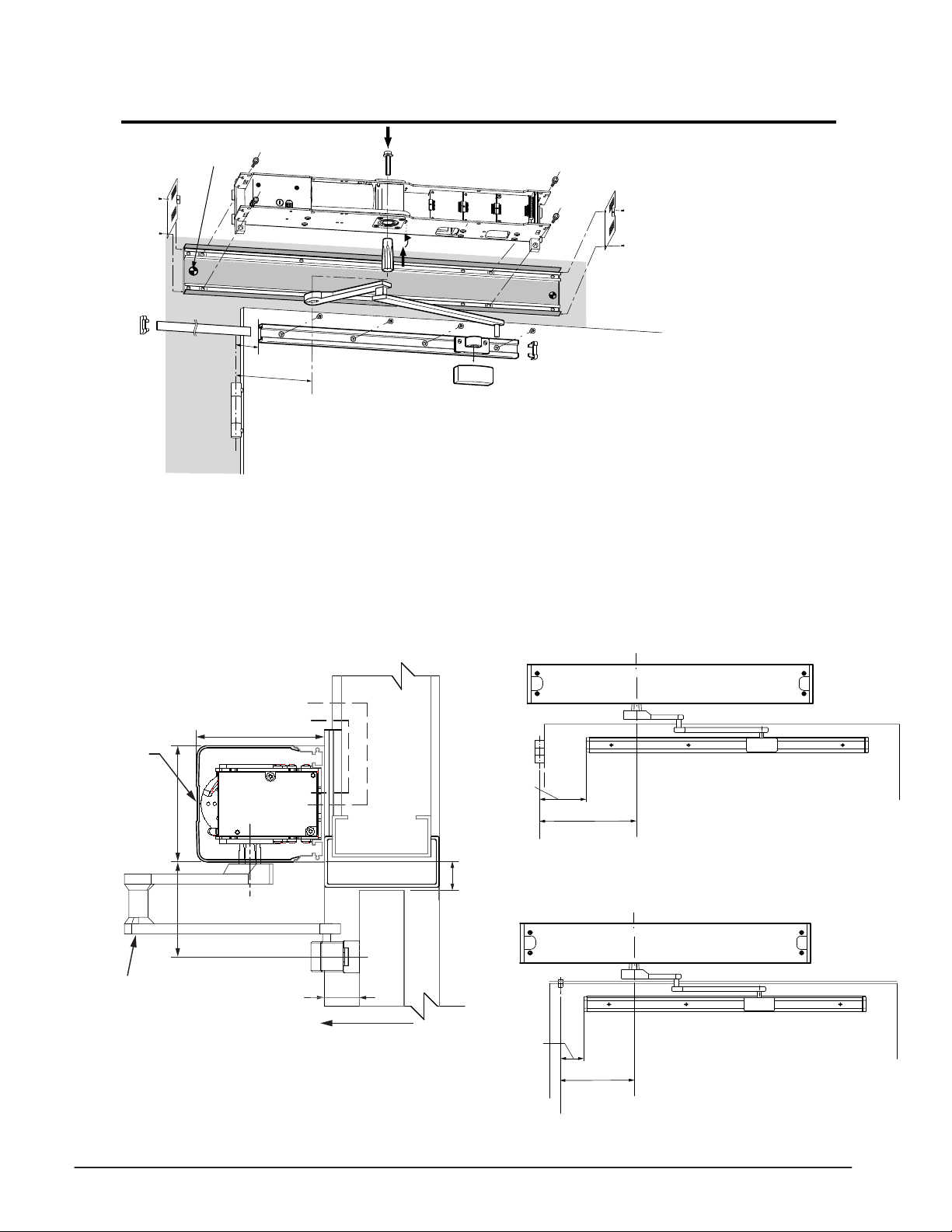
Outswing - Low Energy 8 - 10 lbs Spring Holding Force
Preferred
Primary
Power
1 Push Arm P/N: 408368
0 - 4-
11.41 in. (290 mm)
2 Push Arm P/N: 408369
4-
13.77 in. (350 mm)
3/16” Reveal
1/8” - 9-7/8” Reveal
12-
3/16
” [310]
14-
1/4
” [362]
1) Determine the handing of the operator according to
the door. Note that arrow on operator indicates
opening direction of rotation.
2) Locate & mark output shaft location 12-3/16” from
CL of hinge onto door frame
3) Align header at the bottom of the door frame as shown
below.
4) Secure header to the wall with appropriate hardware.
5) For Stainless Steel Arm refer to illustration on page 13
for mounting dimensions.
Standard Aluminum Arm
Electrical
Controls
5" [127]
TORMAX
1102, 1201
OPERATOR
C
L
Access Cover
4 - 9/16" [116]
Mounting Height
Header
backplate
Reveal Dim.
1,2
CL
Hinge
6) Locate and mount door arm attachment bracket to the
door at Y dimension for shaft used and 14-1/4” from CL of
hinge as shown below.
7) Insert shaft/ drive arm (6) into the operator perpendicular to the
door as shown below. Tighten shaft bolt to 25 ft/ lbs.
8) Manually rotate drive arm (8) as shown below 40°-45°, check
connection point of the two arms to determine how much of the
door portion arm (7) may need to be shortened and/ or cut
off to connect the two arms.
9) Proceed to page 12 to perform commissioning.
CL
14-1/4” [362]
12-3/16” [310]
Header
Hinge
Wall
Y
SWING
DOOR
1/8"
[3]
SWING DIRECTION
Reveal distance is
from the face of the
to the rear of the
Operator 0” - 9-7/8”
X
(0 - 251)
X: Clearance required (distance bottom of header to top of arm)
Y: Distance between bottom of header back plate and centerline
of door mounting shoe
Part No.
141032 (STD)
141106 (D.E.)
141205
Shaft Length
3-
7/32” (82mm)
15/16” (100mm)
34-
27/32” (123mm)
X
1/16” (27mm)
11-25/32” (45mm)
2-
11/16” (68mm)
Y
12-5/32” (55mm)
3-
For extended reveals contact TORMAX
7/16” (36mm)
1/16” (78mm)
7
Rotate Drive Arm
(8) 40° - 45°
NOTE: The door portion arm may need to
be shortened and/ or cut off to
connect the two arms.
Tighten shaft bolt
6
on top of operator
to 25 ft/lbs.
8
11
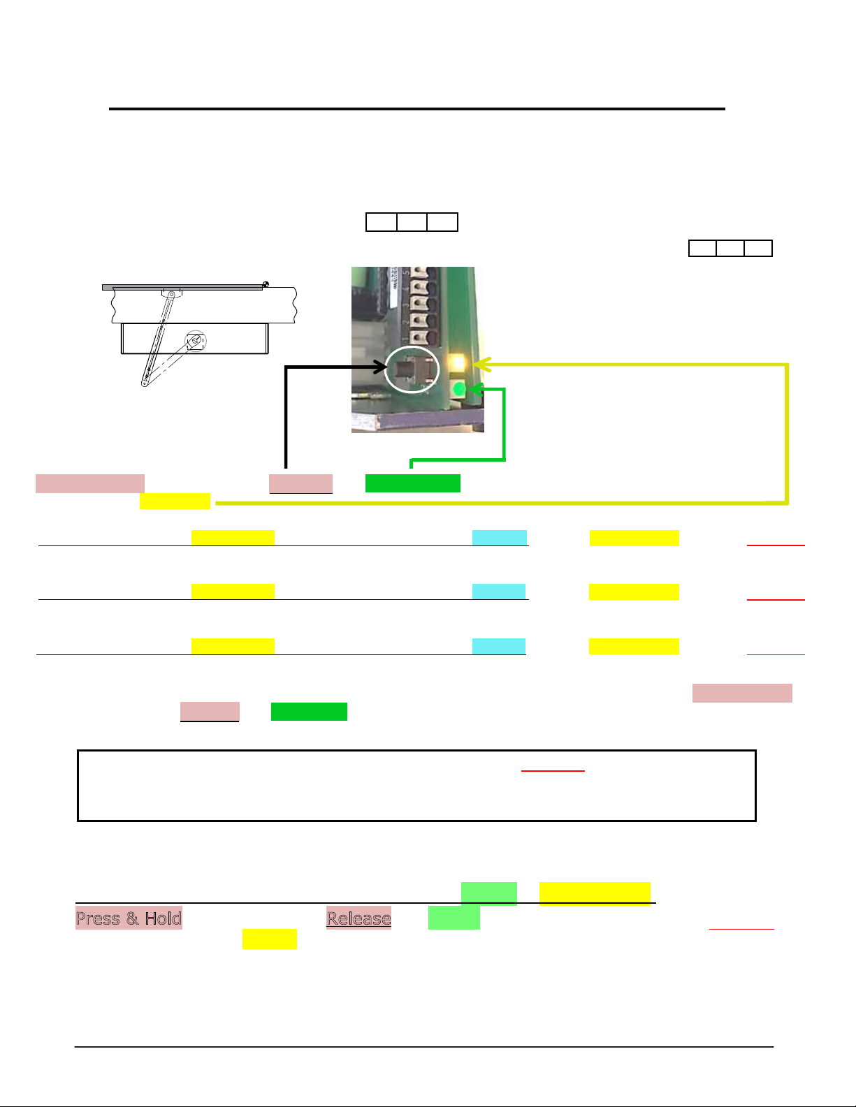
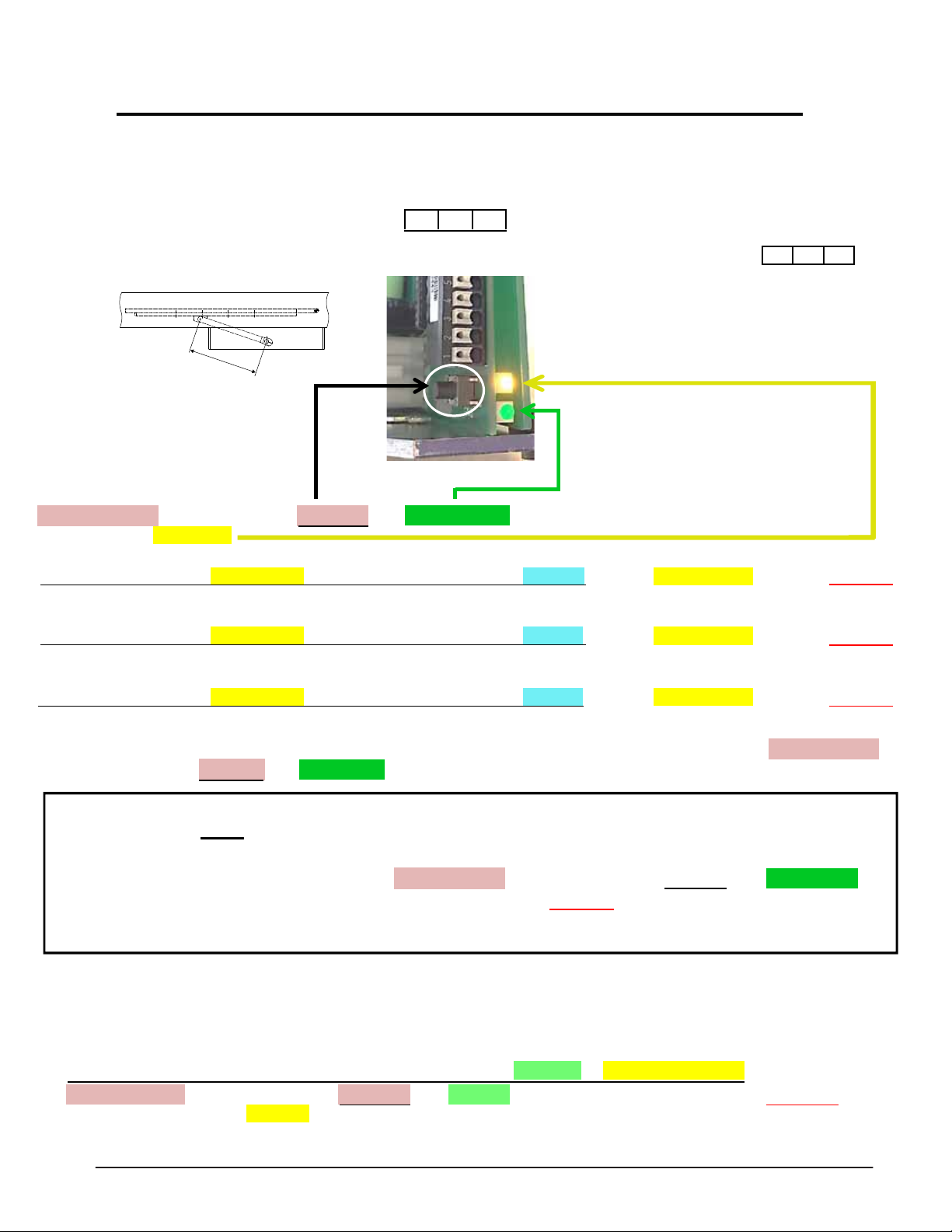
Outswing - Low Energy 8 - 10 lbs Commissioning
Requirements
1. Shaft should be secured into drive unit during mechanical installation.
2. Refer to page 22 to adjust open door stop.
3. Determine system values for your application based on the illustrations on page 10.
Commissioning
Commissioning Example: (3) = 36” door width, (1) = 0-2” reveal, (1) = Standard outswing Arm 11 3/8.
Press & Hold Programming Button, Release after 1 Green LED Flash. The operator will make 1 beep and immediately
begin to flash the Yellow LED.
WHILE LOOKING AT THE YELLOW LED, WAIT FOR THE OPERATOR TO BEEP 1X, then after 3 yellow flashes, Press & Release
Programming Button
WHILE LOOKING AT THE YELLOW LED, WAIT FOR THE OPERATOR TO BEEP 2X, then after 1 yellow flashes, Press & Release
Programming Button
PAUSE
PAUSE
PAUSE
WHILE LOOKING AT THE YELLOW LED, WAIT FOR THE OPERATOR TO BEEP 3X, then after 1 yellow flashes, Press & Release
Programming Button
MADE AN ERROR DON’T WORRY: To start over Disconnect Power for 10 seconds, Reconnect Power, then Press & Hold
Programming Button and Release after 5 Green LED Flashes.
3 1 1
The operator will open 20 degrees stop and beep 2x. Press & Release programming button.
The operator will slowly close and beep 2x, next it will slowly fully open and beep 2x, then close
(beep 1x) followed by 5 beeps, and will cycle fully open & close at normal speed.
Enter Country Code 7 1: (Read Enre Step BEFORE aempng to enter Country Code)
PERFORM
THIS STEP WHILE LOOKING AT BOTH GREEN & YELLOW LEDS.
Press & Hold programming buon, Release aer 7 Green flashes then immediately Press & Release
programming buon aer 1 Yellow flash.
Programming is complete - for further programming enhancements refer to page 23 or Programming Tables
12
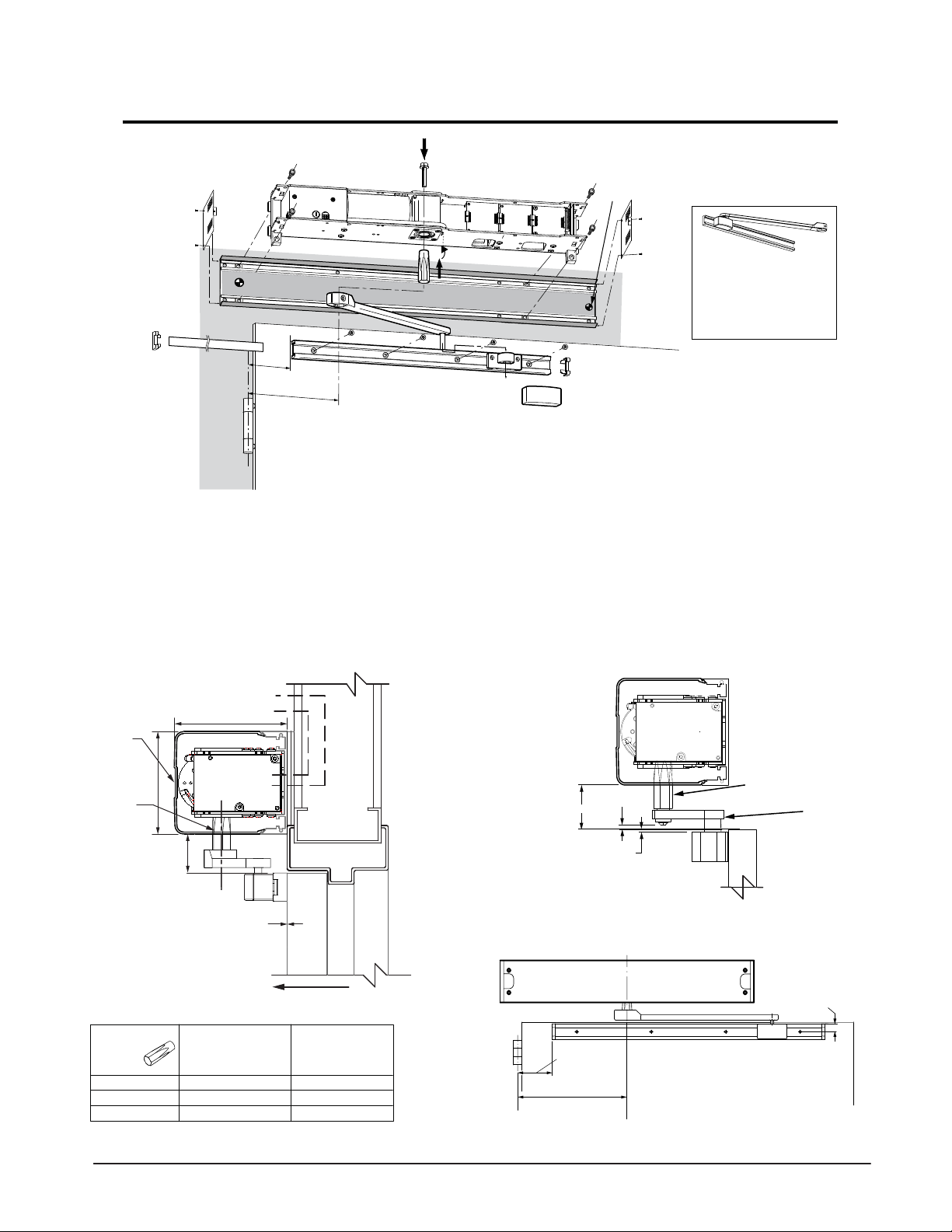
Outswing Full Pedestrian 18 - 20 lbs Spring Holding Force
Preferred
Primary
Power
1 Push Arm P/N: 408368
0 - 4-
11.41 in. (290 mm)
2 Push Arm P/N: 408369
4-
13.77 in. (350 mm)
3/16” Reveal
1/8” - 9-7/8” Reveal
16-
1) Determine the handing of the operator according to
the door. Note that arrow on operator indicates
opening direction of rotation.
2) Locate & mark output shaft location 12-3/16” from
CL of hinge onto door frame
3) Align header at the bottom of the door frame and CL
of the shaft location as shown below.
4) Secure header to the wall with appropriate hardware.
Standard Aluminum Arm
Electrical
Controls
5" [127]
TORMAX
1102, 1201
OPERATOR
C
L
Access Cover
4 - 9/16" [116]
1/8
12-
” [410]
3/16
” [310]
Mounting Height
Header
backplate
Reveal Dim.
1,2
CL
Hinge
5) Locate and mount door arm attachment bracket to the
door at Y dimension for shaft used and 16-1/8” from CL of
hinge as shown below.
6) Insert shaft/ drive arm into the operator, leave shaft bolt loose
until appropriate step during commissioning procedure.
7) Proceed to page 14 to perform commissioning.
Stainless Steel Arm
TORMAX
1102, 1201
C
L
OPERATOR
S.S. Shaft
PT# US801966
11/16" [17]
3/16" [5]
Y
1/8"
SWING
DOOR
SWING DIRECTION
[3]
Reveal distance is
from the face of the
to the rear of the
Operator 0” - 9-7/8”
(0 - 251)
X
X: Clearance required (distance bottom of header to top of arm)
Y: Distance between bottom of header back plate and centerline of door
mounting shoe
Part No.
141032 (STD)
141106 (D.E.)
141205
Shaft Length
3-
7/32” (82mm)
15/16” (100mm)
34-
27/32” (123mm)
X
1/16” (27mm)
11-
25/32” (45mm)
2-
11/16” (68mm)
Y
7/16” (36mm)
12-
5/32” (55mm)
3-
1/16” (78mm)
For extended reveals contact TORMAX
SWING
DOOR
1-3/8" [35]
16-1/8” [410]
12-3/16” [310]
S.S. 0 - 4-3/16” Reveal
Outswing Arm PT# US801983
CL
Hinge
Wall
Header
13
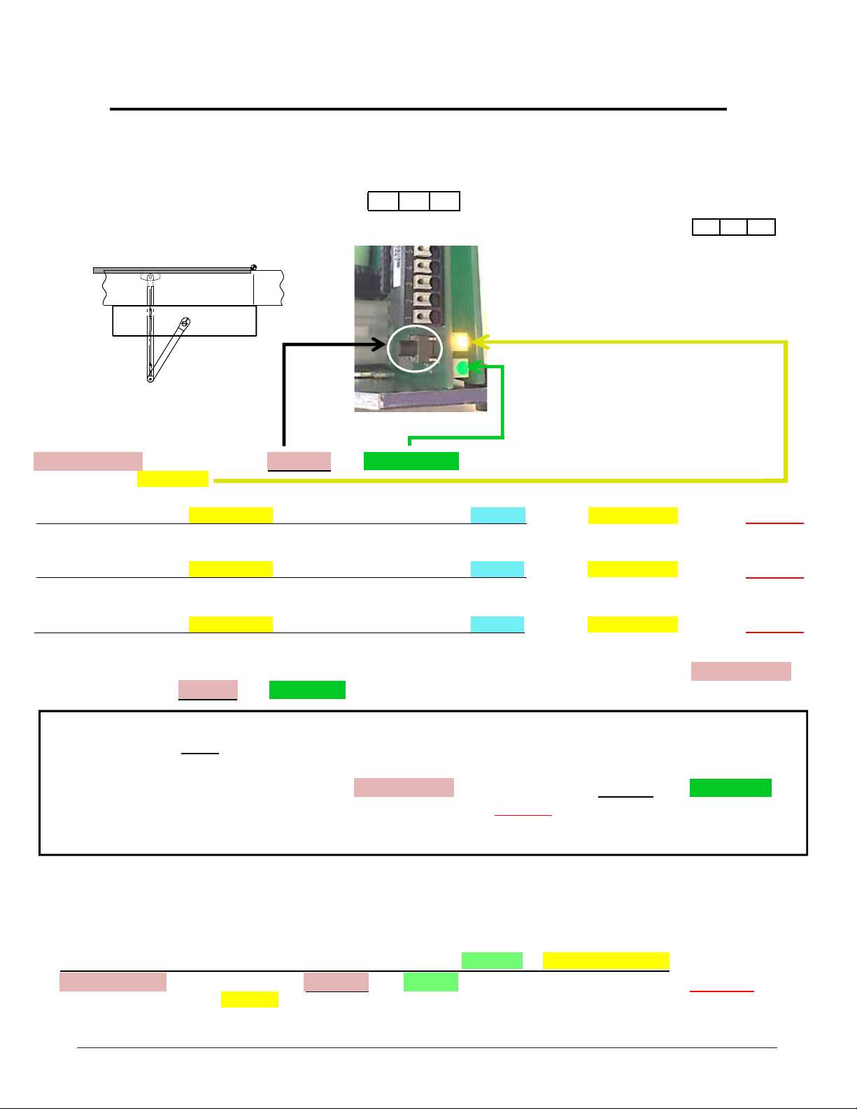
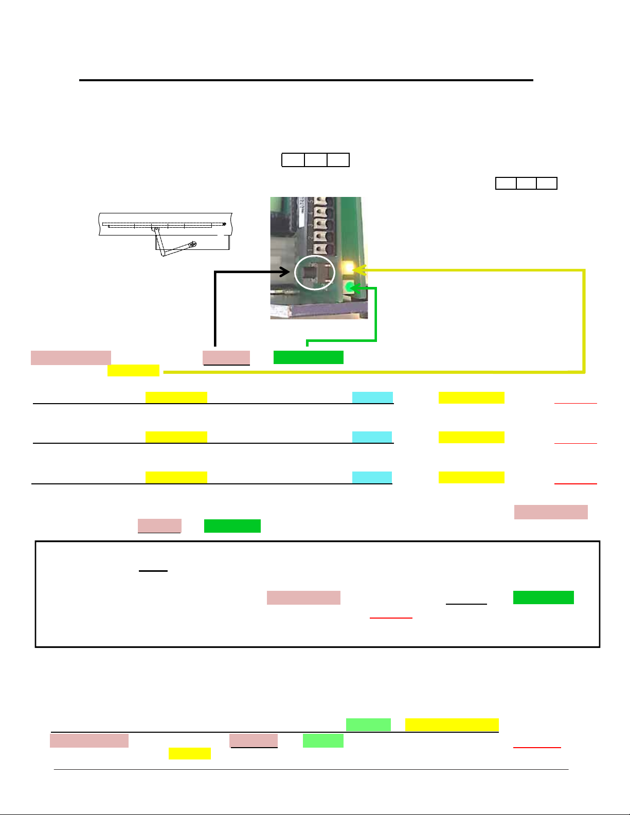
Outswing Full Pedestrian 18 - 20 lbs Commissioning
Requirements
1. Shaft should be loose in the drive unit. Drive arm connected to door and shaft.
2. Determine system values for your application based on the illustrations on page 10.
Commissioning
Commissioning Example: (3) = 36” door width, (1) = 0-2” reveal, (1) = Standard outswing Arm 11 3/8.
Press & Hold Programming Button, Release after 1 Green LED Flash. The operator will make 1 beep and immediately
begin to flash the Yellow LED.
WHILE LOOKING AT THE YELLOW LED, WAIT FOR THE OPERATOR TO BEEP 1X, then after 3 yellow flashes, Press & Release
Programming Button
WHILE LOOKING AT THE YELLOW LED, WAIT FOR THE OPERATOR TO BEEP 2X, then after 1 yellow flashes, Press & Release
Programming Button
PAUSE
PAUSE
PAUSE
WHILE LOOKING AT THE YELLOW LED, WAIT FOR THE OPERATOR TO BEEP 3X, then after 1 yellow flashes, Press & Release
Programming Button
MADE AN ERROR DON’T WORRY: To start over Disconnect Power for 10 seconds, Reconnect Power, then Press & Hold
Programming Button and Release after 5 Green LED Flashes.
3 1 1
The operator will open 20 degrees stop and beep 2x. Attach Door Arm to Shaft and Door, place the Door in the
Closed Position, and
adjust open door stop to desired position, refer to page 22 for adjusting internal Open Door Stop.
RECONNECT POWER (operator beeps 1x), then Press & Hold programming button & Release after 6 Green LED
Flashes. The operator will open 20 degrees stop and beep 2x.
slowly close and beep 2x, next slowly fully open & beep 2x, then close (beep 1x) followed by 5 beeps, and will cycle
fully open & close at normal speed.
NOW Tighten the shaft to the operator at 25 ft-lbs. REMOVE POWER from Operator and
Press & Release programming button. Operator will
Commissioning is complete for High Energy Applications. For Low Energy application complete the last step below
Program the country code into the controller. For additional programming refer to page 23 or Programming Tables.
Enter Country Code 7 1: (Read Entire Step BEFORE attempting to enter Country Code)
PERFORM THIS STEP WHILE LOOKING AT BOTH GREEN & YELLOW LEDS.
Press & Hold
programming button after 1 Yellow flash.
programming button, Release after 7 Green flashes then immediately Press & Release
14
Inswing (Pull) Arm 0” Reveal Installation
Preferred
Primary
Power
4”[102mm]
12-
3/16
”
[310mm]
1) Determine the handing of the operator according to
the door. Note that arrow on operator indicates
opening direction of rotation.
2) Locate & mark output shaft location 12-3/16” from
CL of hinge onto door frame as
3) Determine header mounting height = X. See below.
4) Bolt header to the wall with appropriate hardware.
Standard Aluminum Arm
Electrical
C
L
Controls
TORMAX
1102, 1201
OPERATOR
ACCESS
COVER
4 9/16" [116]
Standard
Shaft 141032
3-7/32” (82mm)
5" [127]
X
Standard Inswing Arm
0” Reveal, P/N 407456
13.77 in. (350 mm
1) )
5) Locate and mount door arm slide track onto the door at
4” from C/L of pivot, mounting holes 5/8” from top of the
door as shown below.
6) Insert shaft/ drive arm into the operator, leave shaft bolt
loose until appropriate step during commissioning
procedure.
7) Proceed to page 16 to perform commissioning.
Stainless Steel Arm
TORMAX
1102, 1201
OPERATOR
S.S. Shaft
PT# US801966
3/16” [5]
1-7/8” [48]
1/8” [3]
Top of
the Door
S.S. 0” Reveal
Inswing Arm
PT# US801996
SWING
0” Reveal
Door Arm
407456
X: Mounting height (distance bottom of header to top of door)
Part No.
141032 (STD)
141205
141020
Shaft Length
3-
7/32” [82mm]
27/32” [123mm]
42-
5/8” [67mm]
DOOR
SWING DIRECTION
X
3/4”” (44mm]
13-
3/8” [86mm]
1-
5/32” [29mm]
For extended reveals contact TORMAX
C/L
Pivot
Header
4”
[102]
12-3/16” [310]
Butt Hingle or Offset Pivot
5/8” [16]
C/L
Shaft
15
Inswing (Pull) Arm 0” Reveal Commissioning
Requirements
1. Shaft should be loose in the drive unit. Drive arm connected to slide track and shaft.
2. Determine system values for your application based on the illustrations on page 10.
Commissioning
Commissioning Example: (3) = 36” door width, (1) = 0-2” reveal, (1) = Standard inswing Arm 11 3/8.
A
Press & Hold Programming Button, Release after 1 Green LED Flash. The operator will make 1 beep and immediately
begin to flash the Yellow LED.
WHILE LOOKING AT THE YELLOW LED, WAIT FOR THE OPERATOR TO BEEP 1X, then after 3 yellow flashes, Press & Release
Programming Button
WHILE LOOKING AT THE YELLOW LED, WAIT FOR THE OPERATOR TO BEEP 2X, then after 1 yellow flashes, Press & Release
Programming Button
PAUSE
PAUSE
PAUSE
WHILE LOOKING AT THE YELLOW LED, WAIT FOR THE OPERATOR TO BEEP 3X, then after 4 yellow flashes, Press & Release
Programming Button
MADE AN ERROR DON’T WORRY: To start over Disconnect Power for 10 seconds, Reconnect Power, then Press & Hold
Programming Button and Release after 5 Green LED Flashes.
3 1 4
The operator will open 20 degrees stop and beep 2x. Attach Door Arm to Slide Track and Shaft, place the Door in the
Closed Position, and
adjust open door stop to desired position, refer to page 22 for adjusting internal Open Door Stop.
RECONNECT POWER (operator beeps 1x), then Press & Hold programming button & Release after 6 Green LED
Flashes. The operator will open 20 degrees stop and beep 2x.
slowly close and beep 2x, next slowly fully open & beep 2x, then close (beep 1x) followed by 5 beeps, and will cycle
fully open & close at normal speed.
NOW Tighten the shaft to the operator at 25 ft-lbs. REMOVE POWER from Operator and
Press & Release programming button. Operator will
Commissioning is complete for High Energy Applications. For Low Energy application complete the last step below
Program the country code into the controller. For additional programming refer to page 23 or Programming Tables.
Enter Country Code 7 1: (Read Entire Step BEFORE attempting to enter Country Code)
PERFORM THIS STEP WHILE LOOKING AT BOTH GREEN & YELLOW LEDS.
Press & Hold
programming button after 1 Yellow flash.
programming button, Release after 7 Green flashes then immediately Press & Release
16
Inswing (Pull) Arm 0 - 6” Reveal Installation
Primary
Power
See details below
1) Determine the handing of the operator according
to the door. Note that arrow on operator indicates
opening direction of rotation.
2) Locate & mark output shaft location as shown
below from CL of hinge or pivot onto door frame.
3) Mark header mounting height of 1 1/8” from the top
of the door as shown below.
4) Secure header to the wall with appropriate hardware.
Electrical
Controls
5" [127]
Access
Cover
TORMAX
4 9/16" [116]
3 3/4” [95]
1102, 1201
OPERATOR
C
L
SWING
DOOR
5) Locate and mount door arm slide track onto the door at 3 3/4”
from bottom of the header and at the dimensions listed below
for the application.
6) Insert shaft/ drive arm into the operator, leave shaft bolt loose
until appropriate step during commissioning procedure.
7) Proceed to page 18 to perform commissioning.
Butt Hinge
Header
2-1/4”
[57]
10-5/8” [270]
C/L
Pivot
1 1/8" [28]
C/L
Shaft
Center Pivot
0 - 6”” Reveal Door Arm
141133 R.H.Shown
141134 L.H.Not Shown
REVEAL DISTANCE
FROM THE FACE OF
THE DOOR TO THE
REAR OF OPERATOR
0"-6" (0-152)
SWING DIRECTION
1-1/4”
[32]
9-7/16”[240]
C/L
Pivot
Header
C/L
Shaft
17
Inswing (Pull) Arm 0 - 6” Reveal Commissioning
Requirements
1. Shaft should be loose in the drive unit. Drive arm connected to door and shaft.
2. Determine system values for your application based on the illustrations on page 10.
Commissioning
Commissioning Example: (3) = 36” door width, (1) = 2-4” reveal, (1) = Extended inswing Arm B.
B
Press & Hold Programming Button, Release after 1 Green LED Flash. The operator will make 1 beep and immediately
begin to flash the Yellow LED.
WHILE LOOKING AT THE YELLOW LED, WAIT FOR THE OPERATOR TO BEEP 1X, then after 3 yellow flashes, Press & Release
Programming Button
WHILE LOOKING AT THE YELLOW LED, WAIT FOR THE OPERATOR TO BEEP 2X, then after 2 yellow flashes, Press & Release
Programming Button
PAUSE
PAUSE
PAUSE
WHILE LOOKING AT THE YELLOW LED, WAIT FOR THE OPERATOR TO BEEP 3X, then after 6 yellow flashes, Press & Release
Programming Button
MADE AN ERROR DON’T WORRY: To start over Disconnect Power for 10 seconds, Reconnect Power, then Press & Hold
Programming Button and Release after 5 Green LED Flashes.
3 2 6
The operator will open 20 degrees stop and beep 2x. Attach Door Arm to Slide Track and Shaft, place the Door in the
Closed Position, and
adjust open door stop to desired position, refer to page 22 for adjusting internal Open Door Stop.
RECONNECT POWER (operator beeps 1x), then Press & Hold programming button & Release after 6 Green LED
Flashes. The operator will open 20 degrees stop and beep 2x.
slowly close and beep 2x, next slowly fully open & beep 2x, then close (beep 1x) followed by 5 beeps, and will cycle
fully open & close at normal speed.
NOW Tighten the shaft to the operator at 25 ft-lbs. REMOVE POWER from Operator and
Press & Release programming button. Operator will
Commissioning is complete for High Energy Applications. For Low Energy application complete the last step below
Program the country code into the controller. For additional programming refer to page 23 or Programming Tables.
Enter Country Code 7 1: (Read Entire Step BEFORE attempting to enter Country Code)
PERFORM THIS STEP WHILE LOOKING AT BOTH GREEN & YELLOW LEDS.
Press & Hold
programming button after 1 Yellow flash.
programming button, Release after 7 Green flashes then immediately Press & Release
18
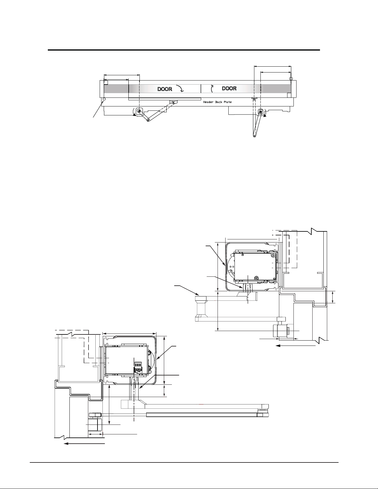
Double Egress Application Installation
”8/50
10 5/8” [270]
”4/12
Butt Hung & Offset Pivot
C/L of
Pivot
1) Determine the handing of the operators according to
the door. Note that arrow on operator indicates
opening direction of rotation.
2) Locate & mark output shaft locations as shown above,
for both operators.
3) Determine header mounting height. If both operators are
in a single header then mount the operators at 1-1/8”
from top of the door as shown below for In-Swing operator.
0 - 6”” Reveal Door Arm
141133 R.H.Shown
141134 L.H.Not Shown
Shaft 141032
16 1/8” [410]
12 3/16” [310]
4) Secure header to the wall with appropriate hardware.
5) Locate and mount door arm and slide track onto the
doors at dimensions listed above.
6) Insert shaft/ drive arms into the operators, leave shaft
bolts loose until appropriate step during commisioning
procedure.
7) Proceed to page 20 to check or connect sync cable and
additional wiring.
In-Swing Operator
Electrical
Controls
TORMAX
1102, 1201
OPERATOR
C
C
L
L
Access
Cover
4 9/16" [116]
Standard
3 7/32” (82)
5" [127]
1 1/8" [29]
Electrical
Controls
Out-Swing Operator
5" [127]
TORMAX
1102, 1201
OPERATOR
SWING
DOOR
SWING DIRECTION
3 9/16" [90]
C
L
REVEAL DISTANCE FROM THE
FACE OF THE DOOR TO THE
REAR OF OPERATOR
0"-9 7/8" (0-251)
4 9/16" [116]
1 1/8" [29]
Access
Cover
Standard D.E. Shaft 141106
3 15/16” (100mm)
3 3/4” [95]
REVEAL DISTANCE
FROM THE FACE OF
THE DOOR TO THE
REAR OF OPERATOR
0"-6" (0-152)
SWING
DOOR
SWING DIRECTION
19
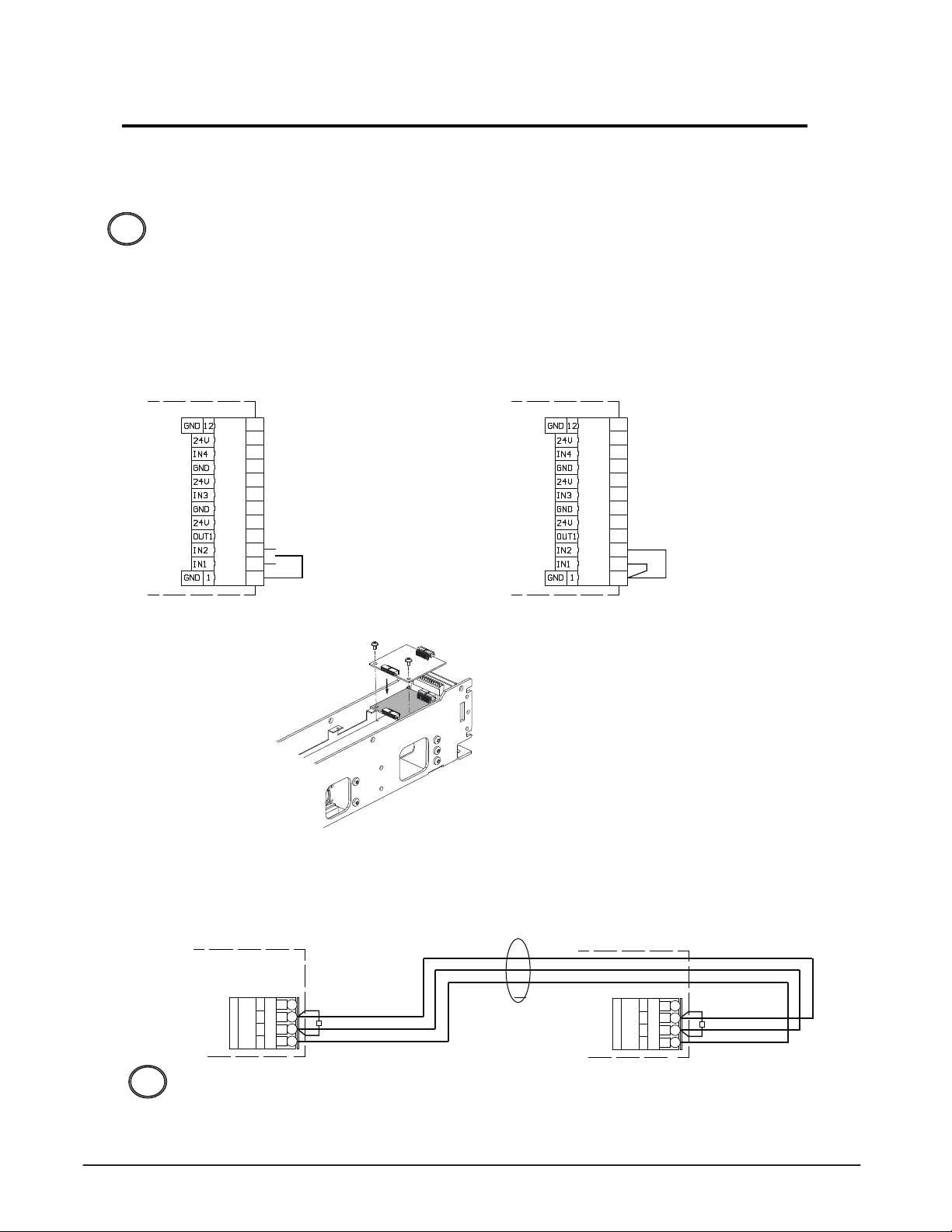
Pair & Double Egress Application Wiring
1. Determine which operator will be the primary drive as this will have the 3-position
switch connection.
The FCP is an option in place of the 3-position and will be connected to the primary
drive with appropriate module, Exterior Door module EDM or Programming Interface
!
module PIM.
2. Check and/ or install jumpers between GND pin 1 - IN1 pin 2 and GND pin 1 - IN2 Pin 3
in place of the 3-position switch on the secondary drive as shown below.
Primary Drive Secondary Drive
Base Door Module BDM Base Door Module BDM
A
12
11
10
9
8
7
6
5
4
OPEN
3
2
1
3-pos.-switchOFF
A
12
11
10
9
8
7
6
5
4
3
2
1
Double door configuration
Recognition as
secondary drive
3. Install Multi Door Module MDM-B into each operator.
T1638_4
4. Connect Sync cable (US801886) to both drives Multi Door Module MDM - B as shown below.
Wiring of Sync Cable
Primary Drive
Multi Door Module MDM-B
A
4
24V
H
3
GND
2
L
1
120 Ω
Red
Green
Black
SYNC
CABLE
Secondary Drive
Multi Door Module MDM-B
A
4
24V
H
3
GND
2
L
1
120 Ω
Red
Green
Black
Do not apply primary power to the drive units until the appropriate step.
!
Proceed to page 21.
20

Pair & Double Egress Application Commissioning
Requirements for Both Operator
1. An MDM module Installed in both operators along with optional modules (PIM, EDM, PDM)
prior to start-up. Refer to Technical Specifications section.
2. Refer to application’s commissioning page to determine shaft condition. (loose or secured)
3. Determine system values based on the illustrations on page 10.
Primary
Secondary
Commissioning
1. Connect primary power 120vAC to Primary operator first, then the Secondary
operator this will configure the operators (Primary/ Secondary).
10AT
L1
L1
N
N
2. Commissioning sequence - Perform Commissioning of Primary operator first,
then perform Commissioning of Secondary operator.
3. Refer to the applications Commissioning page:
115 V~
50/60 Hz
Outswing 8-10 lbs. Spring Holding force (Low Energy) Refer to page 11 for securing the Shaft & Arm position,
Page 12 for commissioning
Outswing 14- 15 lbs. Spring Holding Force (Full Power) - Page14
Inswing 0” Reveal - Page 16
Inswing 0-6” Reveal - Page 18
4. Adjustments:
A
B
Double egress/ simultanious pairs - Turn OFF delayed activation of secondary operator =
Code 830
Frequently used adjustments are listed on page 23
21

Adjustments - Door Stop/ 1201 Spring Tension
Adjusting Internal Open Door Stop
Determine opening angle required for application adjust internal stop accordingly.
–
–
+
+
!
An external door stop may be needed depending on application (abuse, excessive wind...).
!
Mechanical Spring Tension Adjustment (Optional ) - 1201 ONLY
max. 170 °
Adjust spring tension to close the door in adverse applications with no primary power applied.
!
–
+
1. Adjust spring tension on the operator, note Code for the adjustment made.
Example 20mm = Code 5.
0 5 10 15 20 25 30 35 40 Tension length in mm
Number of Flashes
1 * 2 3 4 5 6 7 8 9 Code
2. Programming spring tension adjustment with On-Board Button:
(Read Entire Step BEFORE attempting to enter Country Code)
PERFORM THIS STEP WHILE LOOKING AT BOTH GREEN & YELLOW LEDS.
Press & Hold
programming button after # Yellow flashes for code value .
programming button, Release after 4 Green flashes then immediately Press & Release
3. Changing the spring tension will require a commissioning process to be performed with
On-Board button Code 6 Green flashes or entering Code 021 with FCP.
22

Adjustments - Frequently Used
Adjustments
Country Code configures the operator for Low Energy application for more details refer to
page 31. To set the Country code 7 with On-Board Button follow the instructions below:
Enter Country Code 7 1: (Read Entire Step BEFORE attempting to enter Country Code)
PERFORM THIS STEP WHILE LOOKING AT BOTH GREEN & YELLOW LEDS.
Press & Hold
programming button after 1 Yellow flash.
programming button, Release after 7 Green flashes then immediately Press & Release
Additional adjustments may be made after commissioning which require a PIM
Program Interface module and an FCP. If the door requires or is equipped with an EDM
Exterior Door Module then a PIM in not needed.
Listed below are the most common adjustments. For a complete list of adjustments refer to
the Programming Charts.
*Hold open time = Code 10?
*Push-N-Go OFF = Code 860
*Close Check Force OFF = Code 320
**Power Close for Lock Release ON = Code 581
**Delay Time to Open = Code 591
Power Pulse when Opening = Code 43? Over come wind stack pressure or lock
*Double egress/ simultanious pairs = Code 830
Turn OFF delayed activation of secondary operator for pair applications.
Detecting/ mask out safety functions details on page 31:
On-Board Button = Code 3
FCP = Code 023
Repeat commissioning without system values details on page 31.
On-Board Button = Code 6
Power Assist in AUTO ON = Code 862
Power Assist Hold open Time = Code 150
* Adjustments have been changed by entering Country code 7.
** Adjustment 591 needs to be made in conjunction with 581.
Testing
Test the door in accordance with ANSI A156.19 Power Assist and Low Energy Power
Operated Doors or ANSI A156.10 Power Operated Pedestrian Doors standards before
putting the door into service and handing it over to the End-User.
23

Slim Line - Header Preparation
12-9/32" - Butt Hinges, Inswing (0-6" Reveal)
14-5/8" - C.P. W/1" F.G. (3-3/4") 2-1/8"
13-5/8" - C.P. W/O F.G. (2-3/4") 1-13/16"
16-3/8" - C.P. W/O F.G. (2-3/4") 3-7/8"
14-3/8" - 3/4" Offset Pivots 1-7/8"
17-3/8" - C.P. W/1" F.G. (3-3/4") 4-7/8"
3-3/8"
"C"
RH Outswing Shown.
11/16"
Tormax USA, Inc.
DRAWING IS THE SOLE PROPERTY OF
TORMAX USA. ANY REPRODUCTION IN
PART OR AS A WHOLE WITHOUT THE
WRITTEN PERMISSION OF TORMAX USA
IS PROHIBITED.
1102-1201 Header Fabrication Sheet
Drawing Number \ Revision
Slim Line Swing Door
Header Preparation
Mario Higuera 5/11/2016
THE INFORMATION CONTAINED IN THIS
PROPRIETARY AND CONFIDENTIAL
Description:
1102 / 1201
Door Width + 3-1/2" - 5/8" = Header Width
"8/1-1segniH ttuB - "8/5-31
"B""A"
1-3/16"
1-3/16"
C
L
Output
9/16"
See Chart
"A"
RH Out
LH In
12-3/16"
C
L
Pivot
Cut to Length in Field
As Supplied
or
23-5/8"
A
REVISIONS
"B"
3/8"
11/16"
HM6102/72/4eussI tsriF
DEVORPPAETADNOITPIRCSED.VER
3-5/16"
:etaD:yB nwarD
SHEET 1 OF 2
1-5/8"
24

Slim Line - Application Illustrations
[32]
Pivot
C/L
9-7/16”
[240]
Shaft
C/L
Commissioning and
programming page 18.
Tormax USA, Inc.
Commissioning and
programming page 12.
1-1/4”
Operator Header
Door
3
arm to shorten the length.
May require cutting the
Pivot
C/L
10-5/8” [270]
Shaft
C/L
Center Pivot
Hinge
[57]
CL
Operator Header
2-1/4”
Door
14-1/4” [362]
Wall
1
Butt Hinge
Operator Header
Hinge
CL
12-3/16” [310]
2
Operator Header
4-11/16"
8 - 10 lbs. Spring Holding Force
14-1/4” [362]
programming page 14.
Wall
mounting hole
C/L Bottom
C = 2-5/8"
1-1/2"
Inswing 0” - 6” Reveal
Hinge
CL
bolt loose in the operator.
Leave shaft mounting
12-3/16” [310]
Operator Header
Commissioning and
Pivot
C/L
12-3/16” [310]
4”
[102]
Shaft
C/L
Commissioning and
programming page 16.
5/8” [16]
Door
14 - 15 lbs. Spring Holding Force
16-1/8” [410]
Wall
Butt Hingle or Offset Pivot
Operator Header
2"
1-3/16"
C = 7/8"
mounting hole
C/L Bottom
Outswing
Inswing 0” Reveal
1-5/8”"
mounting hole
C = 2-5/8"
C/L Bottom
Operating manual for commissioning
and programming instructions for
specific applications listed.
DRAWING IS THE SOLE PROPERTY OF
TORMAX USA. ANY REPRODUCTION IN
PART OR AS A WHOLE WITHOUT THE
WRITTEN PERMISSION OF TORMAX USA
IS PROHIBITED.
1102-1201 Header Fabrication Sheet
Drawing Number \ Revision
Mario Higuera 5/11/2016
Applications
aD:yB nwarD
t
:e
SHEET 2 OF 2
Reference 1102/ 1201 Installation and
THE INFORMATION CONTAINED IN THIS
PROPRIETARY AND CONFIDENTIAL
Description:
Slim Line Swing Door
1102 / 1201
Application Wiring page 20, commissioning and
programming page 21.
2-1/4”
[57]
Pivot
C/L
10-5/8” [270]
Shaft
C/L
Arm
Shaft
Pivot
Portion
Door
C/L
12-3/16” [310]
C/L
C/L
16-1/8” [409]
Inswing 0 - 6” Reveal - Butt Hinge
Header
Door
Outswing 14 - 15 lbs. Spring Holding Force
Header
Inswing
mounting hole
C/L Bottom
4-11/16"
C = 2-5/8"
1-1/2"
Double Egress Pair
C= 2-5/8”
1-3/4"
ER
V
FA
tsri
sI
RCSED.
REVISIONS
PPAETADNOITPI
HM6102/72/4eus
DEVOR
25

Programming with the FCP - Overview
Programming with the Functional Control Panel (FCP) refer to T1757 in Technical Specification
section requires at least one of the following modules to be installed PIM shown below refer
!
to T1691 or EDM T1638.
Symbols for
Operating Modes
OFF
AUTOMATIC
REDUCED OPEN
EXIT
OPEN
www.tormaxusa.com
Key (1) increase value
of code (0....9)
OR
selects operating mode
Electric lock
output indicator
Mode P
Manual Operation
Key
OR
selects operating mode
The Functional Control Panel (FCP) has 2 function levels:
Level 1 - End user
- Select operating modes
- Display three-digit fault codes.
- Access protected eliminates
unauthorized programming.
Level 2 - AAADM Certified Technician
- “U” = User readable parameter - allows
technician to read specific parameters.
See programming chart for parameters.
- Access protection, access code (111)
- Programming door system to comply
with the current ANSI A156.10 or
ANSI A156.19 standard.
- Displays currently set parameter.
- 10 min time out after the last programming
entry is made. The technician will be required
PIM
MODULE
to enter the access code (111) to make
further adjustments.
T1691_1
26

Programming with the FCP - Overview
Button 1 - Changes the number or letter by increments of one (0,1,2,3 - 9,a,b,c,...back to 0)
!
Button 2 - Confirms/ enter displayed number or letter into the control.
1) Start Access Code
Indication of operating mode
Press button 1 and 2
simultaneously a “U”
appears, continue to
press until a “C”
appears.
2) Entering Access Code 111
Letter U is shown (= User)
Letter C is shown (= Code)
Release both buttons
Immediately Press
button 2 a “0” will
display.
“0” appears
Press button 1
to display 1
Then
Press button 2
to comfirm/ enter
1st number
Letter P is shown ( = programming)
Press button 2
before P goes
out you will be
able to enter a
parameter.
3) Start Programming Level
Indication of operating mode
Press button 1 and 2
simultaneously a “U”
appears, continue to
press until a “P”
appears.
“0” re-appears
Press button 1 to
display 1
Then
Press button 2
to comfirm/ enter
2nd number
Release both
buttons immediately
Press button 2
a number will
display.
“0” re-appears
Press button 1 to
display 1
Then
Press button 2
to comfirm/ enter
3rd number
4) Entering Parameter
Code 103
any # appears
Press button 1
to display “1”
Then
Press button 2
to comfirm/ enter
1st number
any # appears
Press button 1
to display “0”
Then
Press button 2
to comfirm/ enter
2nd number
If a number is entered incorrectly, stop and let the process time out. (no change made)
!
any flashing # or letter appears
Press button 1 to
display “3”
Then
Press button 2
to comfirm/ enter
3rd number
“P” appears process complete
27

Programming with the FCP
Example 1: Enter access code 111
Display on FCP
Press both buttons simultaneously a U
continue to press both buttons and a C
*Press button 2 and 0
Press button 1 to display 1
Press button 1 1
Press button 1 1
P
will display
will display, release both buttons
will display
Press button 2 to confirm/ enter
Will display
0
Press button 2 to confirm/ enter
Will display
0
Press button 2 to confirm/ enter
Will display,operator is ready to be programmed
Example 2: Enter code 103 to adjust the Hold Open time for 2 sec
Display on FCP
Press both buttons simultaneously a U
continue to press both buttons and a P
Press button 2 and ? a number will be displayed,
Press button 1 to display 1
Press button 1 to display 0
a slow flashing ?
Press button 1 to display 3
will display, release both buttons,
Press button 2 to confirm/ enter,
? A number will be displayed,
Press button 2 to confirm/ enter,
number or letter is displayed,
Press button 2 to confirm/ enter
3
Will rapidly flash for 1 sec
P Will display for 10 sec then operating mode will display.
Hold Open time for Automatic 1 is now set for 2 sec
Within 10 minutes you can enter the programming mode by pressing both keys
!
simultaneously and P will display. If no further adjustments are made after
10 minutes the FCP will time out and require access code re-entry. Repeat example 1.
After confirming/ entering the 2nd number of the code, the 3rd flashing value (number or letter)
!
of the code is the parameter setting. If the value is confirmed the FCP will rapidly flash
for 1 sec then display “P” again.
Quickly pressing and releasing both buttons simultaneously the FCP will return to
!
displaying the mode of operation.
28

Commissioning with FCP
Requirements:
1. Programming with the Functional Control Panel (FCP) requires at least one of the
following modules to be installed PIM refer to T1691 or EDM T1638. If optional modules
(MDM, PDM) are required install prior to start-up.
2. The drive arm is connected to the door and the drive arm shaft has not been
tightened, exception outswing 8 - 10 lbs .
3. Pair of doors - the sync cable and additional wiring outlined on page 20 has been completed.
4. Connect safety sensors to door control, adjust in accordance to manufacturer’s specifications.
Start-up:
Double egress/ simultanious pairs applying power in the wrong sequence will
!
cause configuration problems.
1. Apply primary power to the operator, for pair of doors apply power
to the Primary operator first, then to the Secondary operator.
L1
2. Enter System Parameters - Refer to page 10 to determine values.
Complete sequence for Primary operator first.
Enter Code 06? Door width
Enter Code 07? Distance of drive arm
Enter Code 08? Sliding lever length
3. Arm Preload
Enter Code 021 operator will rotate 20 degrees, with the door arm connected to the door,
place the door in the closed position, tighten shaft retaining bolt to 25 ft.lbs.
Remove primary power plug from operator, door will close.
L1
10AT
L1
N
N
4. For pair applications - repeat process for secondary operator beginning at step 2.
10AT
L1
N
N
115 V~
50/60 Hz
115 V~
50/60 Hz
5. Adjusting Open door stop
Determine opening angle required for application adjust internal stop accordingly.
–
–
+
+
!
An external door stop may be needed depending on application (abuse, excessive wind ).
!
max. 170 °
Proceed to page 30
29

Commissioning with FCP
Commissioning
1. Apply primary power to the operator, for pair of doors apply power
to the Primary operator first, then to the Secondary operator.
2. Commissioning - Enter Code 021 Start commissioning, for pairs complete primary operator
sequence first.
3. Door will automatically open and hold open at 20 degrees.
4. Exit Preload - Enter Code 020 door closes.
5. Door will automatically begin opening until the open door stop is reached, door will
immediately close.(Checking door weight/ momentum)
6. Escalating 6 tones will occur before door begins opening. (Door mounted safety sensor
inhibiting)
7. For pair applications, repeat sequence for secondary operator, begin at step 2. Primary
operator will go to the open position until commissioning is completed.
Additional Adjustments
Additional adjustments may need to be made after commissioning. Listed below are the most
common adjustments. For additional adjustments refer to the Programming Charts.
*Hold open time = Code 10?
*Push-N-Go OFF = Code 860
*Close Check Force OFF = Code 320
**Power Close for Lock Release ON = Code 581
**Delay Time to Open = Code 591
Power Pulse when Opening = Code 43? Over come wind stack pressure
*Double egress/ simultanious pairs = Code 830
Turn OFF delayed activation of secondary operator for pair applications.
Detecting/ mask out safety functions details on page 31 = Code 023
Power Assist in AUTO ON = Code 862
Power Assist Hold open Time = Code 150
Repeat commissioning without system values details on page 31.
On-Board Button = Code 6
* Adjustments have been changed by entering Country code 7.
** Adjustment 591 needs to be made in conjunction with 581.
Testing
Test the door in accordance with ANSI A156.19 Power Assist and Low Energy Power Operated Doors or
ANSI A156.10 Power Operated Pedestrian Doors standards before putting the door into service and handing
it over to the End-User.
L1
2 Audible Tones
2 Audible Tones
6 Audible Tones This ends the programming step.
10AT
L1
N
N
115 V~
50/60 Hz
30

Code Descriptions/ BDM LED Displays
Country Code
The Country code is available in firmware V3.02 and above. The country code provides preset
values to aid the technician in installing the door to comply with ANSI Standard A156.19.
Country code can be set with On-board button Code 7/1 or FCP code 031. To remove the
country code adjustments perform a factory reset. Functions changed are listed below:
Hold Open Time=105 Opening Speed=203 Closing Speed=214
Closing Force=311 Close Check Force=320 Safety Function BDM IN4=602
Safety Function PDM IN4=651 Pair without Overlap=830 Push N Go OFF=860
Detecting safety features (optional)
If the safety sensors in the opening and/or closing direction were not detected correctly or
have been connected for the first time, they can be subsequently detected. Detect and save
safety features 1–2
Code 3 on-board configuration (FCP code = 023 )
Procedure according to Code 023 or OB Code 3 Conditions Result
Waiting time 5 seconds (rising motor signal tone).
The safety sensor connection type is detected.
The door opens and closes again.
After the door reaches the open position, the number
of testable safety sensors is indicated by the number of
times the green LED (0–2 times).
Sensors must be
correctly connected.
Do not enter the
detection area of the
moving safety sensors.
If the testing of the safety feature “open” is
success
ful, the door opens at full power.If the
testing of the safety feature “close” is
successful, the door closes at full power.
The safety feature “open” is automatically
suppressed if the door moves against a wall.
Repeat commissioning (without system values)
If the door arm or shaft position was changed or glass was installed in the door after
commissioning.
Code 6 on-board configuration
Procedure according to OB Code 6
Operator rotates 20°, beeps 2x, Press & Release the
OB button, operator will close slowly, automatically
opens slowly & fully open & beeps 2X, close (beep
1x) followed by 5 beeps. and will fully open & close
at normal speed.
Displays
Troubleshooting codes displays as E / H on the user interface. See the Troubleshooting Codes Chart in this manual
for their meaning.
LED displays on the base door module BDM
Yellow LED off OK
Yellow LED on Error (E). See the user interface or Skipper for the error display.
Green LED on Power supply and module OK
Green LED off No power supply or power supply overloaded.
Green LED flashes A programming step was started via the on-board programming button.
The Green LED flashes
after the open position is
reached
See the Trouble shooting chart in this manual.
The process is on going. Press the button briefly to stop the process.
0 × = No testable safety feature available. Door moves with low energy.
1 × = 1 testable safety feature available. Door move
2 × = 2 testable safety features available. Door moves with full energy.
Conditions
Door travel path unobstructed, no physical
contact with the door
during the learn cycles.
Minimal wind load.
Result
Door open & closed positions detected. Door
weight detected.
Safety functions detection according to Code 023,
OB Code 3.
s with low energy.
31

Programming Table
Code Function Note
01 1
UR Door operator type 1102
01 2 UR Door operator type 1201
02 0 End procedure "Spring preload"
02 1 Start commissioning
02 2 Start Teach-In
02 3 Detecting and storing of safety functions
02 4 Delete registration of unplugged modules MDM, PDM, EDM
03 1
Preset 1=Handicap Function (=OB code 7/1) (=P105,203,214,311,320,602,651,830,860,870)
04 0 UR Reset
04 1 Factory Reset
04 2
UR Display firmware version
04 3 UR Display number of cycles
04 4 UR Display number of operating hours
04 5 Delete fault protocol
05 0 Display registration module EDM
05 1 Display registration module PDM
05 2 Display registration module MDM
05 3 Display registration secondary door operator
05 4 Display voltage intermediate circuit 40VDC
05 5 Display voltage 24VDC supply
05 8 Display temperature transformer (calculated) (from FW V03.10)
05 9 Display temperature motor (calculated) (from FW V03.10)
06 1...8 Door width (=OB code 1/1)
0 * 1 2 3 4 5 6 7 8 code
0
28” 32” 36” 40” 44” 48” 52” 56” inches
07 1...6 Reveal (=OB code 1/2)
0 * 1 2 3 4
0 1-2” 2-4” 4-6” 6-8.5”
5
8.5-10.5”
6
10.5-12.5”
08 1...6 Drive Arm Length (=OB code 1/3)
2
3
0 * 1
11-3/8”
0
Custom 13-3/4”
4 5 6
Custom
13-3/4”
Custom
09 0...9 Spring tension (=OB code 4) ONLY APPLIES to 1201 Operator
1 * 2 3 4 5 6 7 8 9
5
0
10 15 20 25 30 35 40 mm
10 0...F UP Hold-open time for Auto Mode
0 1 * 2 3 4 5 6 7 8 9 A b C d E F code
0 1 2 3 4 5 6 7 8 9 10 15 20 40 60 >/> sec. (>/>=step control)
11 0...F UP Hold-open time of activator for Beds
0 1 2 3 4 5 6 7 8 * 9 A b C d E F code
0 1 2 3 4 5 6 7 8 9 10 15 20 40 60 >/> sec. (>/>=step control)
12 0...F UP Key Switch Hold-open time
0 1 2 3 * 4 5 6 7 8 9 A b C d E F code
0 1 2 3 4 5 6 7 8 9 10 15 20 40 60 >/> sec. (>/>=step control)
13 0...9 UP Delay time Mode of op. OFF
0 1 2 * 3 4 5 6 7 8 9 code
1 3 5 7.5 10 15 20 30 45 60 sec.
14 0...9 UP out3 EDM: Bell active time
0 1 2 * 3 4 5 6 7 8 9 code
0 0.5 1 2 3 4 5 6 8 10 sec.
15 0...9 Power Assist Hold- open time after opening
0 1 *
0
2
3 4 5 6 7 8 9 code
1
2 3 4 5 6 8 10 12.5 sec.
A
15
b
17.5
C d E
20
UP=(P) Program mode. UR=(R) Read parameter mode
40
60
Remains after factory reset
Remains after factory reset
Only possible after entering system parameters 06x, 07x, 08x
Safety functions on terminals in3+4 PDM" and in4 BDM
The modules will be registered automatically at power-up
Reverse with factory reset
Starts program with calibration run
All adjustments back to default values (see *)
Example: r06_00 = V06.00
Example: c10_302 = 10'302 cycles (max. 99?999?999)
Example: h4_002 = 4002 hours (max.99'999'999)
A0 =not registered, A1 =registered
A0 =not registered, A1 =registered
A0 =not registered, A1 =MDM-A registered, A2 =MDM-B registered
A0 =Single door, A1 =primary door, A2 =secundary door
Example: u22_8 = 22,8V
Example: u22_8 = 22,8V
Example: t39_5 = 39,5 degree C
Example: t39_5 = 39,5 degree C
code
inches
code
inches (Out-Swing Arm/ Push 1,2,3) (In-Swing Arm/ Pull 4,5,6)
Is also determined by the teach-in.
0 = Off
0 = Off
F
>/>
* = Default value
32

Programming Table
Code Function Note
20 0...9 UP Opening speed
8
130
120
120 130
9
9
Low Energy max 67N / F (+0 to -30%)
9
30
Low Energy max 67N / F (+0 to -30%)
Low energy max 67N / F (+0-30%) / S= only force of spring
Low energy max 67N / F (+0-30%) / S= only force of spring
% of the set spring force.
Force on door edge
0 = 5 degrees before the closed position
Stop = open against endstop (not if H17 is displayed)
Valid only from FW V02.10
Note the context of the parameters P22x, P32x, P42x
0 = off, 3 = maximum
0 1 2 3 4 5 6 * Code
10 25 40 55 70 85 100 %
7
110
21 0...9 UP Closing speed
0 1 2 3 4 5 6 * Code
10 25 40 55 70 85 100 %
7 8
110
22 0...9 Close check speed
0 * 1 2 3 4 5 6 7 8 code
2 5 8 11 14 17 20 23 26 N (no= no limit)
30 1...9 UP Motor force opening
1 2 3 4 5 6 * 7 8 9 code
40 55 67 80 95 120 150 175 no N (no= no limit)
31 0...9 UP Motor force closing
0 1 2 3 4 5 6 * 7 8 9 code
S 40 55 67 80 95 120 150 175 no N (no = no limit)
32 0...8 UP Motor force at close check
0 1 2 3 4 5 6 * 7 8 code
S 40 55 67 80 95 120 150 175 N (max)
33 0...6 Motor holding closed force (New commissioning required! >H14)
0 1 2 3 * 4 5 6 code
-90 -60 -30 0 +30 +60 +90 %
34 1...5 Power Assist closing force after opening
0 * 1 2 3 4 5 code
S 5 10 15 20 25 N (S=Spring force)
35 0...9 Reversing time obstacle opening
0 1 2 3 4 5 6 * 7 8 9 code
5 4.5 4 3.5 3 2.5 2 1.5 1 0.5 sec.
36 0...9 Reversing time obstacle closing
0 1 2 3 4 5 6 * 7 8 9 code
5 4.5 4 3.5 3 2.5 2 1.5 1 0.5 sec.
37 1...5 Power Assist opening resistance
0 1 2 3 * 4 code
5 10 15 20 25 N
38 0...6 UP Push-and-Go/ Power Assist start angle
0 1 2 3 * 4 5 6 code
1 2 3 5 8 12 16 degree
39 0...5 UP Push-and-Close start angle
0 1 2 3 4 5 * code
- 8 10 12 14 16 degree
40 0...9 Correction open position
0 1 2 3 4 * 5 6 7 8 9 code
95 97 98 99 100 101 102 103 105 Stop %
41 1...9 Advance angle for unlocking
1 2 3 4 5 6 7 * 8 9 code
1 1.5 2 2.5 3 3.5 4 4.5 5 degree
42 0...9 Angle for close & open check
0 * 1 2 3 4 5 6 7 8 9 code
0 1 1.5 2 2.5 3 3.5 4 4.5 5 degre
43 0 *...3 Power pulse when opening
UP=(P) Program mode. UR=(R) Read parameter mode
* = Default value
33

Programming Table
Code Function Note
50 0 No switch off safety sensors
50 1 Switch off safety sensors in: P
50 2 * Switch off safety sensors in: P, OFF if door closed >60s, OPEN >60s
51 0 No switch off activator sensors
51 1 Switch off sensor in: P
51 2 * Switch off sensor in: P, OFF if door closed, OPEN
51 3 Switch off sensor in: P, OFF and EXIT if door closed, OPEN
52 0 No switch off of LED on User Interface USIN-7
52 1 * Switch off LEDs on user interface USIN-7 1 min. after use
55 0 Locks in operating mode OFF
55 1 Locks in operating mode OFF, EXIT
55 2 Locks in operating mode OFF, AUTO, EXIT
55 3 * Locks in operating mode OFF, AUTO, EXIT, P
56 0 * out2 EDM: Without holding magnet function
56 1 out2 EDM: Holding magnet active in closed position
56 2 out2 EDM: Holding magnet active in open position
57 0 * out1B EDM: Electric strike: current-free locked - fail secure
57 1 out1B EDM: Electric strike/ Maglock: current-free unlocked - fail safe
57 2 out1B EDM: No lock
57 3 out1B EDM: Motorised lock
58 0 * No power close for electric strike release
58 1 Power close for electric strike release
59 0...b Delay time to open (or until response "R" for motorised lock)
0 * 1 2 3 4 5 6 7 8 9 A b code
0,1 0.2 0.4 0.8 1.2 1.6 2 2.5 3 4 R/NO R/NC sec. / Response
60 0 in4 BDM: No function
60 1 * in4 BDM: Safety swing area
60 2 in4 BDM: Safety closing with reversing function
60 3 in4 BDM: Safety closing with creeping function
60 4 in4 BDM: Safety opening with stop function
60 5 in4 BDM: Safety opening with creeping function
60 6 in4 BDM: Power-assistance pre-triggering
61 0 out1 BDM: No function
61 1 * out1 BDM: Message “General fault”
61 3 out1 BDM: Message "door closed"
61 4 out1 BDM: Message “door closed and locked”
61 5 out1 BDM: Message “door open”
61 6 out1 BDM: Message “Mode of operation OFF”
62 0 * in1 PDM: No function
62 1 in1 PDM: Emergency closing
62 2 in1 PDM: Emergency opening
64 0 * in3 PDM: Safety opening with stop function
64 1 in3 PDM: Safety opening with function "Low-Energy"
64 2 in3 PDM: Safety stop
64 3 in3 PDM: Safety swing area
65 0 * in4 PDM: Safety closing with reversing function
65 1 in4 PDM: Safety closing with function "Low-Energy"
65 2 in4 PDM: Safety stop
65 3 in4 PDM: Safety swing area
UP=(P) Program mode. UR=(R) Read parameter mode
Connect power of sensor to GNDct (PDM)
Connect power of sensor to GNDct (PDM)
Connect power of sensor to GNDct (EDM)
Connect power of sensor to GNDct (EDM)
Connect power of sensor to GNDct (EDM)
LEDs switch on when needed
When using electric. strikes: 100% duty ratio required
When using electric. strikes: 100% duty ratio required
When using electric. strikes: 100% duty ratio required
Only for electric strike with 100% duty ratio
With return signal: Programm P59A or B
Requires min. unlocking time of 0,2s (P591)
Only valid if electric strike has to unlock
Safety functions use only once with 60x, 64x, 65x!
Contact type NO, NC detect with code P023 or OB 3
Contact type NO, NC detect with code P023 or OB 3
Contact type NO, NC detect with code P023 or OB 3
Contact type NO, NC detect with code P023 or OB 3
Contact type NO, NC detect with code P023 or OB 3
Function depending of op. mode and P85x-87x, x>=2
Only with response of motorised lock
Contact type NC
Contact type NC
Contact type NC+test, NC, NO detect with P023 or OB 3
Contact type NC+test, NC, NO detect with P023 or OB 3
Contact type NC+test, NC, NO detect with P023 or OB 3
Contact type NC+test, NC, NO detect with P023 or OB 3
Contact type NC+test, NC, NO detect with P023 or OB 3
Contact type NC+test, NC, NO detect with P023 or OB 3
Contact type NC+test, NC, NO detect with P023 or OB 3
Contact type NC+test, NC, NO detect with P023 or OB 3
* = Default value
34

Programming Table
Code Function Note
70 0 * out1 MDM: Message “door open”
70 1 out1 MDM: Battery in service
71 0 * out2 MDM: Message "door closed"
72 0 * out3 MDM: Message “door closed and locked”
72 1 out3 MDM: Message “General fault”
73 0 * out4 MDM: Door ready for operation
73 1 out4 MDM: Mode of operation OFF
74 0 in1 MDM: no function
74 1 * in1 MDM: Mode of operation OFF
75 0 in2 MDM: no function
75 1 * in2 MDM: Mode of operation OPEN
76 0 in3 MDM: no function
76 1 * in3 MDM: Mode of operation EXIT
77 0 in4 MDM: no function
77 1 * in4 MDM: Passage for beds
77 2 in4 MDM: Operation mode MANUAL
80 0 * UP out3 EDM: Bell trigger: Activator outside
80 1 UP out3 EDM: Bell trigger: Activator inside
80 2 UP out3 EDM: Bell trigger: Key switch
81 0...4 UP Button pressed time for handicapped
0 * 1 2 3 4 code
0 1 2 3 5 sec.
82 0 * Emergency operation in case of faulty safety > for low risk
82 1 Safety operation in case of faulty safety > for high risk
83 0 Double wing door without overlapping, synchronous
83 1 * Double wing door with overlapping
83 2 Double wing door with "Door coordinator device" MDC
84 0 * Battery switches off after 10s
84 1 Battery operation in all modes of operation
84 2 Battery operation in AUTO, EXIT, OPEN
84 3 Opens with battery in OFF, AUTO, EXIT, OPEN
84 4 Opens with battery in AUTO, EXIT, OPEN
85 0 * No opening assistance in MANUAL
85 2 Power-assistance in MANUAL incl. pre-trigger by activator in-/outside
85 3 Power-assistance in MANUAL
86 0 No opening assistance in AUTO
86 1 * Push & Go in AUTO
86 2 Power-assistance in AUTO
87 0 No opening assistance in EXIT
87 1 * Push & Go in EXIT
87 2 Power-assistance in EXIT
90 0 * Programming button (BDM) released
90 1 Programming button (BDM) disabled
91 0...4 UP Access code lock for control unit
0 * 1 2 3 4 code
-- 111 222 333 123 code
92 0 * User parameter enabled
92 1 User parameter disabled
UP=(P) Program mode. UR=(R) Read parameter mode
MDM- A (Non Stocking part, special order)
MDM- A (Non Stocking part, special order)
MDM- A (Non Stocking part, special order)
MDM- A (Non Stocking part, special order)
MDM- A (Non Stocking part, special order)
MDM- A (Non Stocking part, special order)
MDM- A (Non Stocking part, special order)
MDM- A (Non Stocking part, special order)
MDM- A (Non Stocking part, special order)
MDM- A (Non Stocking part, special order)
MDM- A (Non Stocking part, special order)
MDM- A (Non Stocking part, special order)
MDM- A (Non Stocking part, special order)
MDM- A (Non Stocking part, special order)
MDM- A (Non Stocking part, special order)
MDM- A (Non Stocking part, special order)
Valid for inside/outside and key switch activations
At E31-36: Creep speed with force <67N
At E31-36: Manual operation
Application see T-1763, T1753
Application see T-1763, T1753
Application see T-1763, T1753
In all other modes, the battery switches off after 10s
In all other modes, the battery switches off after 10s
In all other modes, the battery switches off after 10s
+ Triggered by angle or in4 BDM (in4 only with P510)
Triggered by angle or pre-release by IN4 BDM
Triggered by angle or pre-release by IN4 BDM
Triggered by angle or pre-release by IN4 BDM
0 = off
* = Default value
35

Troubleshooting Codes
* E = Error | H = Hint
* No. Fault Behaviour of System Reset
E0x Internal test negative. Fatal error. Safety operating
E11 Motorised lock not unlocked Door blocked Automatically if OK
E12 Motorised lock not locked Automatically if OK
E23 CAN connection EDM interrupted Safety operating mode
E24 CAN connection PDM interrupted Safety operating mode
E25 CAN connection MDM interrupted Safety operating mode
E26 CAN connection primary - second. interrupted Primary continues, second. stays closed
E31 Safety open > 1 min. active, test neg. According safety function Automatically if OK
E32 Safety closing > 1 min. active, test neg. According safety function Automatically if OK
E33 Safety stop > 1 min. active, test neg. According safety function Automatically if OK
E34 Safety swing area > 1 min. active, test neg. According safety function Automatically if OK
E35 Safety open creep > 1 min. active, test neg. According safety function Automatically if OK
E36 Safety close creep > 1 min. active, test neg. According safety function Automatically if OK
E37 Safety open Low En. > 1min. active, test neg. According safety function Automatically if OK
E38 Safety clos. Low En. >1min. active, test neg. According safety function Automatically if OK
E41 Activator inside > 1min. active Door remains open Automatically if OK
E42 Activator outside > 1min. active Door remains open Automatically if OK
E43 Key switch > 1min. active Door remains open Automatically if OK
E45 Emergency open > 1 min. active Door remains open Automatically if OK
E46 Emergency close > 1 min. active Door closes and remains closed Automatically if OK.
E47 Inhibit switch > 1 min. active Door closes without hold open time Automatically if OK.
E48 Activator bed passage > 1min. active Door remains open Automatically if OK
E51 Encoder not working Safety operating mode Reset
E61 Power supply 40V outside of admissible range Safety operating mode Automatically if OK
E62 Power Supply 24V outside of permissible range Safety op. mode Automatically if OK
E63 Power Supply 24V short circuit Safety op. mode Automatically after 20s if OK
E64 Motor hot Safety operating mode Automatically after cooling down
E66 Motor faulty. Interruption of motor control. Safety operating mode. No braking! Replace motor
E68 Power failure (Power on)
E99 Error at secondary drive unit
H01 System was started Safety op. mode Reset
H02 Factory reset required (VEE unreadable) Safety mode Factory reset
H11 Parameter 06... not yet programmed Safety operation Enter parameter
H12 Parameter 07... not yet programmed Safety operation Enter parameter
H13 Parameter 08... not yet programmed Safety operation Enter parameter
H14 Commissioning not executed Safety operation Start commissioning
H15 Timeout moving. Door blocked. Motor faulty Commissioning is canceled Restart commissioning
H16 Mass detection faulty (wind, opening angle) Autom. detection is terminated Restart automatic detection
H17 Open endstop too soft. Motor may overheat
H18 Safety function is used more than once See P60x, P64x, P65x
H19 Detection of safety functions pending P023 or OB code 3
H21 Teach-In: Door moves >25 s before start Abort Teach-In New Teach-In
H22 Teach-In: No start within 60s Abort Teach-In New Teach-In
H23 Teach-In: Movement to slow. >60 s Abort Teach-In New Teach-In
H31 Obstacle detection at opening Door reverses Automatically, Display 20s.
H32 Obstacle detected at closing Door reverses Automatically, Display 20s.
H33 Permanent obstacle at opening Safety operation Reset
H34 Permanent obstacle at closing Safety operation Reset
H46 FW missmatch in primary and secondary
H62 Calibration run in closing direction Searches closed position At the end of movement
H67 Absolute position not found yet Slow opening movement
H71 Battery mode Door moves slowly Power supply return
H74 Motor current in open position too high E64 can trigger later P404. Avoid wind load. Install HM
Power OFF-ON. Possibly press button 5s
36

Control Connection Diagram
Connect components only with primary power removed (current-less).
Terminal Allocation in Default Programming
Base Module (BDM) Power Door Module (PDM)
A
12
11
10
T1655_1e
9
8
7
6
5
4
3
2
1
swing area
Error message
OPEN
AUTO
OFF
3-Pos. switch
Sensor inside
Safety
Exterior Door Module (EDM)
A
Sensor
outside
Key switch
T1655_3e
1)
OUT1
24 VDC/ max. 1 A
self resetting
B
C
2)
A
C
T1655_2e
Bell
Holding magnet
Electric Lock
Code 57?(0, 1, 2)
Jumper required
for Electric Lock
Inhibit switch
No function
Safety closing
Safety opening
OUT1/ OUT3
24 VDC/ max. 1 A
self resetting
OUT1 A/B
potential free
max. 1 A (at
68 ˚F)
< 40 VDC, 30 VAC
self resetting
1)
1)
OUT1-2 / GNDct
max. 1 A
self resetting
1)
Multi Door Module (MDM -B)
A
Multi Door Module (MDM -A) - (Non Stocking part, special order)
A
Double door
B
1) Function programmable
2) OUT 1A & OUT 1B are Normally Open dry contact
Load on power supply 24 VDC max. 1.5 A/36 W
Double door
IN4 Passage for beds
IN3 Op. mode EXIT
IN2 Op. mode OPEN
IN1 Op. mode OFF
C
Networking
D
OUT4 Message
1)
1)
1)
1)
T1655_4e
“Door operational”
OUT3 Message
“Door closed and locked”
OUT2 Message
“Door closed”
OUT1 Message
“Door open»
1)
1)
1)
1)
37

Connection Diagram
4) Refer to Larco Ultra-Small Receiver Installation Guide for proper setup and adjustments.
2) To make additional adjustments an FCP - Functional Control Panel will be needed.
3) Adjust operator to be in accordance with ANSI A156.19
NOTE:
1) Enter the Country Code (OBC=7/1) or (FCP=031) as this will limit/ reduce your opening and closing speeds,
forces, turns Push n Go function OFF and sets Hold Open time to 5 seconds.
OFF / AUTO / HOLD OPEN
OPEN
PUSH
TO
OPEN
PUSH
TO
Common
NO
Switch
Jamb
OPTIONAL
GND 1
IN1
OFF
2
1
WHITE
RED
IN2
H/O
3
BLUE
OUT1
4
24V
5
GND
6
3 Position Switch
GND
24V
8
24V
IN4
10
11
9
IN3
7
GND 12
12
A
1102/ 1201 Basic
Board (BDM)
Drawn by:
Date: 8/29/17
Drawing #: 1201002 Revision #: 02
Jerry Morgan
Revised by: GDM
Title:
1201/ 1102 Single with Larco 433 Activation
BROWN / WHITE
Transmitter
TO OPEN
PUSH
TORMAX USA Inc.
12859 Wetmore Rd. San Antonio, Tx 78247
Interior
ORANGE
BLACK
RED
Ultra Small Receiver
Larco 433
Transmitter
TO OPEN
PUSH
Exterior
38

Connection Diagram
NOTE:
1) Enter the Country Code (OBC=7/1) or (FCP=031) as this will limit/ reduce your opening and closing speeds,
forces, turns Push n Go function OFF and sets Hold Open time to 5 seconds.
2) To make additional adjustments an FCP - Functional Control Panel will be needed.
3) Adjust operator in accordance with ANSI A156.19.
TO OPEN
OPEN
PUSH
PUSH
TO
OPEN
Common
TO
PUSH
NO
Wall
Jamb
Interior Push
Plate
GND 1
IN1
OFF
2
1
WHITE
RED
IN2
H/O
3
BLUE
OUT1
4
OFF / AUTO / HOLD OPEN
3 Position Switch
GND
IN3
24V
7
6
5
24V
8
GND
9
GND 12
24V
IN4
10
12
11
1102/ 1201 Basic
Board (BDM)
A
Drawn by:
Date: 8/29/17
Drawing #: 1201001 Revision #: 02
Jerry Morgan
Revised by: GDM
Title:
TORMAX
12859 Wetmore Rd. San Antonio, Tx 78247
1201/ 1102 LE Single with hard wired push plates
USA Inc.
Common
TO OPEN
PUSH
NO
Exterior Push
Plate
39

Connection Diagram
4) Refer to manufacturers Installation/ Users guides to setup and adjust the OA - EDGE, SuperScan,
and Larco Receiver.
3) Adjust operator and sensors to be in accordance with ANSI A156.19.
NOTE:
1) Determine which door mounted sensor is being installed reference wiring connections listed to the right .
2) Enter Code 602 to program IN4 for Safety Closing with Reversing Function.
BASIC DOOR MODULE TERMINALS A9
OA - EDGE (PUSH SIDE)
SUPERSCAN (PUSH SIDE)
OR
8 7 6 5
BROWN
A11
WHITE
A9
GREEN
A10
YELLOW
GND 1
WHITE
IN1
OFF
RED
IN2
H/O
BLUE
switch
OUT1
GND
24V
3-pos.
Basic Door Module (BDM)
A
GND 12
GND
24V
IN3
IN4
24V
10
12
11
987654321
on Push Side, Larco Receiver FW 3.00
Drawn by:
Date: 8/29/17
Drawing #: 1201008 Revision #: 02
Jerry Morgan
Revised by: GDM
Title:
12859 Wetmore Rd. San Antonio, Tx 78247
1201 / 1102 Single LE with Door Mounted Sensor
Brown/ White
Orange
Black
Red
TORMAX USA Inc.
Ultra Small Receiver
AND / OR
Larco 433
HARD WIRED
PUSH PLATE
ACTIVATION
40

Connection Diagram
6) Refer to manufacturers Installation/ Users guides to setup and adjust the
Eagle and/ or Larco Receiver.
3) If installing an OA-EDGE sensor on both sides of the door the Brown & White wires will be connected to
pins C1 & C4 only.
4) The OA-EDGE monitoring settings should be Dipswitch A7=OFF, A8=OFF, B3=ON.
5) Adjust operator and sensors to be in accordance with ANSI A156.10.
NOTE:
1) Do not enter the Country Code (OBC=7/1) or (FCP=031) as this will limit/ reduce your opening and closing forces.
2) Reference wiring connections listed to the right for door mounted sensor being installed.
POWER DOOR MODULE TERMINALS C1 C2 C3 C4
SUPERSCAN (PULL SIDE)
OA - EDGE (PULL SIDE)
OR
7 6 5 8
BROWN
PINK
BLUE
WHITE
SUPERSCAN (PUSH SIDE)
7 6 5 8
POWER DOOR MODULE TERMINALS C5 C6 C7 C8
OA - EDGE (PUSH SIDE)
OR
BROWN
YELLOW
GREEN
WHITE
OA - Edge
OUT1
GND
IN3
3 2 1
Safety opening (Pull)
24V
GND
IN4
Safety closing (Push)
OUT2
Power Door Module-(PDM)
GND 1
OUT1
IN1
IN2
WHITE
OFF
24V
H/O
BLUE
RED
3-pos.
switch
C
A
GND
GND
24V
IN2
IN1
4
3 2 1
8
7 6 5 4
Inhibit switch
No function
GND
GND
IN3
24V
987654321
Basic Door Module (BDM)
A
GND 12
24V
IN4
10
12
11
, SuperScan,
Larco Receiver, Eagle, FW 3.00
Drawn by:
Date: 8/16/17
Drawing #: 1201007 Revision #: 02
Jerry Morgan
Revised by: GDM
Title:
12859 Wetmore Rd. San Antonio, Tx 78247
1201 / 1102 Single with Door Mounted Sensors,
Brown/ White
TORMAX USA Inc.
SENSOR
EAGLE
1 2 3 4 5
AND / OR
Ultra Small Receiver
Black
Orange
Red
AND / OR
Larco 433
HARD WIRED
PUSH PLATE
ACTIVATION
41

Connection Diagram
3) Refer to manufacturers Installation/ Users guides to setup and adjust the
2) Install jumper into PDM C terminal pin 6,7 as shown above for power assist close functionality.
3) Adjust operator and sensors to be in accordance with ANSI A156.10.
Eagle and/ or Larco Receiver.
NOTE:
1) Do not enter the Country Code (OBC=7/1) or (FCP=031) as this will limit/ reduce your opening/ closing speeds
and forces.
BASIC DOOR MODULE TERMINALS A6 A7 A9 A10
LZR Microscan (ACTIVATION)
(OVERHEAD PRESENCE)
WHITE
GREEN
WHITE
BLACK
GREEN
BLACK
LZR Microscan (PULL SIDE)
BLACK
YELLOW
RED
WHITE
RED
RED
POWER DOOR MODULE TERMINALS C1 C2 C3 C4
LZR Microscan
OUT1
GND
IN3
3 2 1
Safety opening (Pull)
24V
OUT2
GND
IN4
Jumper
Safety closing
(Push)
Power Door Module-(PDM)
GND 1
OUT1
IN1
IN2
WHITE
OFF
RED
H/O
BLUE
24V
3-pos.
switch
C
A
GND
GND
24V
IN2
IN1
4
3 2 1
7 6 5 4
8
Inhibit switch
No function
GND
GND
IN3
24V
987654321
Basic Door Module (BDM)
A
GND 12
24V
IN4
10
12
11
,
Drawn by:
Date: 8/22/17
Drawing #: 1201013 Revision #:
Jerry Morgan
Revised by:
SENSOR
EAGLE
Larco Receiver, Eagle, FW 3.00
Title: FE
TORMAX USA Inc.
12859 Wetmore Rd. San Antonio, Tx 78247
1 2 3 4 5
1201 / 1102 Single with LZR Microscan Sensors,
Brown/ White
AND / OR
Ultra Small Receiver
Larco 433
Black
Orange
Red
AND / OR
ACTIVATION
HARD WIRED
PUSH PLATE
GREY
GREY
Switch
ORANGE
LZR Microscan
Closed Door
Position
ORANGE
LZR Microscan
42

Connection Diagram
NOTE:
1) Enter the Country Code (OBC=7/1) or (FCP=031) as this will limit/ reduce your opening and closing speeds,
forces, turns Push n Go function OFF and sets Hold Open time to 5 seconds.
2) To make additional adjustments an FCP - Functional Control Panel will be needed.
3) Adjust operators to be in accordance with ANSI A156.19
4) Sync cable has a 120 ohm resistor at both ends.
5) Jumpers must be connected to Secondary operator A Terminals 1 to 2, 1 to 3.
Plates
Drawn by:
Date: 8/29/17
Drawing #: 1201003 Revision #: 02
Jerry Morgan
Title:
1201/ 1102 LE Pair with Hard Wired Push
Primary Drive
Basic Door Module (BDM)
TO OPEN
PUSH
Wall
Interior Push
GND
Multi Door Module MDM-A
A
24V
H
L
3 2 1
4
120 Ω
GND 1
WHITE
IN1
OFF
RED
IN2
H/O
BLUE
OUT1
GND
IN3
24V
24V
GND
987654321
A
GND 12
24V
IN4
10
12
11
Plate
green
black
OPEN
red
PUSH
TO
3-pos.
switch
Jamb
OPEN
PUSH
TO
Common
NO
CABLE
SYNC
Common
NO
TO OPEN
PUSH
TORMAX USA Inc.
12859 Wetmore Rd. San Antonio, Tx 78247
Exterior Push
Plate
GND
black
24V
H
L
4
3 2 1
120 Ω
green
red
Multi Door Module MDM-B
A
GND 1
secondary drive
GND
OUT1
IN1
IN2
24V
OFF
H/O
Recognition as
GND
IN3
24V
987654321
Basic Door Module (BDM)
Secondary Drive
A
GND 12
24V
IN4
10
12
11
Revised by: GDM
43

Connection Diagram
4) Sync cable has a 120 ohm resistor at both ends.
5) Refer to Larco Ultra-Small Receiver Installation Guide for proper setup and adjustments.
2) To make additional adjustments an FCP - Functional Control Panel will be needed.
3) Adjust operators to be in accordance with ANSI A156.19
NOTE:
1) Enter the Country Code (OBC=7/1) or (FCP=031) as this will limit/ reduce your opening and closing speeds,
forces, turns Push n Go function OFF and sets Hold Open time to 5 seconds.
OPEN
PUSH
TO
OPEN
PUSH
TO
Common
NO
Switch
BROWN / WHITE
ORANGE
BLACK
RED
Ultra Small Receiver
Larco 433
OPTIONAL
Jamb
GND
GND
L
black
L
black
24V
H
3 2 1
4
120 Ω
green
red
CABLE
SYNC
24V
H
3 2 1
4
120 Ω
green
red
Multi Door Module MDM-A
A
GND 1
Multi Door Module MDM-B
A
GND 1
GND
OUT1
IN1
IN2
24V
OFF
H/O
WHITE
BLUE
RED
3-pos.
switch
GND
OUT1
IN1
IN2
24V
OFF
H/O
Recognition as
secondary drive
Primary Drive
Basic Door Module (BDM)
A
GND 12
GND
IN3
24V
IN4
24V
10
12
11
987654321
Basic Door Module (BDM)
Secondary Drive
A
GND 12
GND
IN3
24V
IN4
24V
10
12
11
987654321
Activation, Optional Jamb Switch
Drawn by:
Date: 8/30/17
Drawing #: 1201004 Revision #: 02
Jerry Morgan
Revised by: GDM
Title:
TORMAX USA Inc.
12859 Wetmore Rd. San Antonio, Tx 78247
1201/ 1102 LE Pair with Larco 433 Receiver
TO OPEN
PUSH
Transmitter
Exterior
TO OPEN
PUSH
Transmitter
Interior
44

Connection Diagram
NOTE:
1) Determine which door mounted sensor is being installed reference wiring connections listed to the right .
2) Reference 1201/1102 Installation & Service manual for details of dual operator installation and commissioning.
3) Enter Code 602 to program IN4 for Safety Closing with Reversing Function.
4) Adjust operator and sensors to be in accordance with ANSI A156.19.
5) Refer to manufacturers Installation/ Users guides to setup and adjust the OA - EDGE, SuperScan
and Larco Receiver.
Push Side, Larco Receiver FW 3.00
Drawn by:
Date: 8/29/17
Drawing #: 1201009 Revision #: 02
Title:
12859 Wetmore Rd. San Antonio, Tx 78247
1201 / 1102 Pair LE with Door Mounted Sensors
BASIC DOOR MODULE TERMINALS A9
OA - EDGE (PUSH SIDE)
SUPERSCAN (PUSH SIDE)
OR
Multi Door Module-MDM-B
A
GND
24V
H
L
3 2 1
4
GND 1
IN1
OFF
IN2
H/O
OUT1
Basic Door Module (BDM)
A
GND 12
GND
GND
24V
24V
IN3
IN4
24V
10
12
11
987654321
Secondary Drive
120 Ω
green
black
8 7 6 5
BROWN
red
A11
WHITE
A9
GREEN
A10
YELLOW
CABLE
SYNC
BASIC DOOR MODULE TERMINALS A9
Basic Door Module (BDM)
OA - EDGE (PUSH SIDE)
SUPERSCAN (PUSH SIDE)
OR
8 7 6 5
BROWN
black
green
120 Ω
red
GND 1
WHITE
Multi Door Module-MDM-B
3 2 1
4
L GND
24V
H
A
IN1
OFF
RED
IN2
H/O
BLUE
OUT1
24V
3-pos.
switch
GND
IN3
A
GND 12
GND
24V
IN4
24V
10
12
11
987654321
Primary Drive
A11
WHITE
A9
GREEN
A10
YELLOW
TORMAX USA Inc.
Jerry Morgan
Revised by: GDM
Brown/ White
Orange
Black
Red
Ultra Small Receiver
Larco 433
AND / OR
PUSH PLATE
ACTIVATION
HARD WIRED
45

Connection Diagram
POWER DOOR MODULE TERMINALS C1 C2 C3 C4
6) Refer to manufacturers Installation/ Users guides to setup and adjust the
5) Adjust operator and sensors to be in accordance with ANSI A156.10.
Eagle and/ or Larco Receiver.
3) If installing an OA-EDGE sensor on both sides of the door the Brown & White wires will be connected to
pins C1 & C4 only.
4) The OA-EDGE monitoring settings should be Dipswitch A7=OFF, A8=OFF, B3=ON.
NOTE:
1) Do not enter the Country Code (OBC=7/1) or (FCP=031) as this will limit/ reduce your opening and closing forces.
2) Reference wiring connections listed to the right for door mounted sensor being installed.
SUPERSCAN (PULL SIDE)
OA - EDGE (PULL SIDE)
SUPERSCAN (PUSH SIDE)
OR
7
BROWN
6 5 8
PINK
BLUE
WHITE
7
6
5
8
POWER DOOR MODULE TERMINALS C1 C2 C3 C4
SUPERSCAN (PULL SIDE)
OA - EDGE (PULL SIDE)
SUPERSCAN (PUSH SIDE)
OA - Edge
OR
, SuperScan,
7
BROWN
6 5 8
PINK
BLUE
WHITE
7
6
5
8
POWER DOOR MODULE TERMINALS C5 C6 C7 C8
OA - EDGE (PUSH SIDE)
OR
BROWN
YELLOW
GREEN
WHITE
POWER DOOR MODULE TERMINALS C5 C6 C7 C8
OA - EDGE (PUSH SIDE)
OR
BROWN
YELLOW
GREEN
WHITE
OUT1
GND
IN3
3 2 1
Safety opening (Pull)
OUT1
GND
IN3
3 2 1
Safety opening (Pull)
GND
24V
GND
24V
IN4
C
OUT2
GND
24V
IN4
8
7 6 5 4
Safety closing (Push)
C
OUT2
GND
24V
8
7 6 5 4
Safety closing (Push)
Power Door Module-(PDM)
A
GND
IN2
IN1
4
3 2 1
Inhibit switch
No function
CABLE
SYNC
Power Door Module-(PDM)
A
GND
IN2
IN1
4
3 2 1
Inhibit switch
No function
Multi Door Module-MDM-B
A
GND
24V
H
L
4
3 2 1
120 Ω
green
black
red
green
black
red
120 Ω
Multi Door Module-MDM-B
3 2 1
4
24V
H
L GND
A
GND 1
GND 1
WHITE
IN1
OFF
IN1
OFF
RED
IN2
H/O
IN2
H/O
OUT1
OUT1
BLUE
switch
GND
24V
GND
24V
3-pos.
Basic Door Module (BDM)
A
GND 12
GND
24V
IN3
IN4
24V
10
12
11
987654321
Secondary Drive
Basic Door Module (BDM)
A
GND 12
GND
24V
IN3
IN4
24V
10
12
11
987654321
Primary Drive
Drawn by:
Date: 8/16/17
Drawing #: 1201006 Revision #: 02
Jerry Morgan
Revised by: GDM
Larco Receiver, Eagle, FW 3.00
Title:
TORMAX USA Inc.
12859 Wetmore Rd. San Antonio, Tx 78247
1201 / 1102 Pair with Door Mounted Sensors,
SENSOR
EAGLE
1 2 3 4 5
Brown/ White
AND / OR
Ultra Small Receiver
Larco 433
Black
Orange
Red
AND / OR
PUSH PLATE
ACTIVATION
HARD WIRED
46

Connection Diagram
BASIC DOOR MODULE TERMINALS A6 A7 A9 A10
4) Refer to manufacturers Installation/ Users guides to setup and adjust the
Larco Receiver.
3) Adjust operator and sensors to be in accordance with ANSI A156.10.
NOTE:
1) Do not enter the Country Code (OBC=7/1) or (FCP=031) as this will limit/ reduce your opening/ closing speeds
and forces.
2) Install jumper into PDM C terminal pin 6,7 as shown above for power assist close functionality.
LZR Microscan (ACTIVATION)
(OVERHEAD PRESENCE) (OVERHEAD PRESENCE)
WHITE
GREEN
WHITE
BLACK
GREEN
BLACK
BASIC DOOR MODULE TERMINALS A6 A7 A9 A10
LZR Microscan (ACTIVATION)
LZR Microscan, Eagle and/ or
WHITE
GREEN
WHITE
BLACK
GREEN
BLACK
LZR Microscan (PULL SIDE)
BLACK
YELLOW
RED
WHITE
RED
RED
LZR Microscan (PULL SIDE)
BLACK
YELLOW
RED
WHITE
RED
RED
POWER DOOR MODULE TERMINALS C1 C2 C3 C4
GND
IN3
POWER DOOR MODULE TERMINALS C1 C2 C3 C4
GND
IN3
Safety opening (Pull)
OUT1
GND
24V
3 2 1
Safety opening (Pull)
Jumper
(Push)
OUT1
GND
24V
IN4
3 2 1
Jumper
(Push)
IN4
Safety closing
OUT2
Safety closing
OUT2
Power Door Module-(PDM)
C
A
GND
GND
24V
IN2
IN1
4
3 2 1
7 6 5 4
8
Inhibit switch
No function
CABLE
SYNC
Power Door Module-(PDM)
C
A
GND
GND
24V
IN2
IN1
4
3 2 1
8
7 6 5 4
Inhibit switch
No function
Multi Door Module-MDM-B
A
GND
24V
H
L
3 2 1
4
120 Ω
green
black
red
green
black
red
120 Ω
Multi Door Module-MDM-B
3 2 1
4
L GND
24V
H
A
GND 1
GND 1
WHITE
IN1
OFF
IN1
OFF
Basic Door Module (BDM)
A
GND 12
GND
GND
OUT1
IN2
H/O
24V
24V
IN3
IN4
24V
10
12
11
987654321
Secondary Drive
Basic Door Module (BDM)
A
GND 12
GND
GND
OUT1
IN2
24V
H/O
BLUE
RED
24V
IN3
IN4
24V
10
12
11
987654321
Primary Drive
3-pos.
switch
Date: 8/22/17
Drawing #: 1201014 Revision #:
Revised by:
Larco Receiver, Eagle, FW 3.00
Title: FE
Drawn by:
TORMAX USA Inc.
12859 Wetmore Rd. San Antonio, Tx 78247
1201 / 1102 Pair with LZR Microscan Sensors,
Jerry Morgan
SENSOR
EAGLE
1 2 3 4 5
Brown/ White
AND / OR
Ultra Small Receiver
Larco 433
Black
Orange
Red
AND / OR
ACTIVATION
HARD WIRED
PUSH PLATE
GREY
GREY
Switch
ORANGE
LZR Microscan
Closed Door
Position
ORANGE
LZR Microscan
47

TECHNICAL SPECIFICATIONS
1000009
Area of application
Release
Mechanical Documentation
Shaft Removal
iMotion 1301, 1201, 1102 Swing Door Operator
August 2016
AUTOMATIC
12859 Wetmore Road
San Antonio, TX 78247
1-888-685-3707
WWW.TORMAXUSA.COM
Technician ReferenceUse
Purpose
Provide guidance in the removal of the drive arm shaft for a 1301,1201, 1102 operator. Removal of
the shaft will require the extraction bolt part# US801643.
Removal
1. Remove power from the operator, remove the arm assembly from the shaft.
2. Remove the shaft retaining bolt part# US801528 as shown in illustration #1.
3. Insert the shaft extraction bolt into the operator & shaft as shown in illustration #2
4. Using a 6 mm hex head allen wrench turn the bolt in a clockwise direction, screwing in the
extraction bolt. The bolt pushes the shaft out of the operator as shown in illustration #3.
Operator Steel
retaining collar
Shaft Bolt
Illustration #1
Operator Steel
retaining collar
Illustration #2
Operator Steel
retaining collar
Illustration #3
48

TECHNICAL SPECIFICATIONS
T1253e Cable Plan
iMotion 1201
6
7
9
No.
1
2
Control Components Notes Cable Length (ft) Length (ft)
Activator/Push-button
inside
Activator/Push-button
outside
5 User interface iMotion
Connected with
FCC-connector
User interface iMotion
Connected with
LIN-Adapter
8
1 2 3 4 5 10 11
Stranded wire
recommended
Stranded wire
recommended
4 × 20 AWG
4 × 20 AWG
Stranded wire
recommended
Stranded wire
recommended
hone ribbon cable
P
6 x 0.14 mm
RJ12,6P,6C
3 × 0,25 mm
Stranded wire
recommended
Stranded wire
recommended
GWA02×4kcolrooD9
Stranded wire
recommended
Stranded wire
recommended
GWA41×3hctiwsniamsniaM21
2
2
12
10 A
115v AC
without screen with screen
< 98 < 328
< 98 < 328
< 328GWA02×…tupnI4
< 98
< 98 < 100
< 82 < 328
< 98GWA02×2…1egasseM01
< 328098<GWA02×2hctiws-yeK3
< 328< 98GWA02×4gnisolcrotavitcaytefaS6
< 328< 98GWA02×4gnineporotavitcaytefaS7
< 328
< 328< 98GWA02×2…2egasseM11
49

TECHNICAL SPECIFICATIONS
T-1633e 1201 Technical Information
Drive type TORMAX 1201 Swing Door Drive
Drive system Electro-mechanical drive with DC-motor, extensible with modules, spring activated
closing or opening.
Control System MCU42
Door leaf width and mass 28” – 56”, up to 551 lbs. according to diagram
573
529
485
440
396
352
308
264
220
176
132
Door leaf mass [lbs.]
88
44
0
Opening angle 70 ° … 110 ° max.
Speed 5 °… 60 °/s max.
Mains connection 230/115 V AC, 50/60 Hz
Dimensions 3-11/32” x 5-3/64” x 25-13/64”
2 leaves with mechanical door coordinator: 100 × 135 × door width
Power consumption 3 … 200 W
Automatic reset in the event of a
power failure
Protective class IP 20
Ambient temperature – 68 … 122° F
Weight: 26 lbs
Emitted noise level < 70 dBA
Sensor supply 24 VDC (+0.5–1.5 V) Pmax. 36 W, Imax. 1.5 A
Inputs 24 VDC or potential-free (Multi Door Module MDM-A)
Outputs Holding magnet 24 VDC, < 0.25 A (Exterior Door Module EDM)
Interfaces CAN for double door and air lock (MDM-A/MDM-B)
Approvals and standards CE
Durability DIN 18650 (TÜV) – 1 Million test cycles at
In the closing an
100 % of maximum force according to DIN 1154 corresponds to closer parameter
4-6 with the linkage pushing and closer parameter 3 when the linkage is pulling.
Bell 24 VDC, < 1 A, (Exterior Do
El. door opener 24 VDC, < 1 A, (Exterior Door Module EDM)
Potential-free 24 VDC, < 1 A, (Multi Door Module MDM-A)
Test-out 24 VDC, < 1 A, (Power Door Module PDM)
RS232 for Skipper (EDM, Programming Interface Module PIM)
RS485 (MDM-A)
LIN-Bus (EDM, Programming Interface Module PIM))
EN 16005 (TÜV)
UL 325
UL 228
EN 61000-6-2, EN 61000-6-3, EN 60335-1
4000
cycles per day
28 32
36 40 44 5248 56
Door leaf width [inches]
T1633_1e
d opening direction; capable of an infinitely variable setting: 60–
or Module EDM)
50

TECHNICAL SPECIFICATIONS
T-1634e 1102 Technical Information
Drive type TORMAX 1102 Swing Door Drive
Drive system Electro-mechanical drive with DC-motor, extensible with modules, spring activated
closing or opening.
Control System MCU42
Door leaf width and mass 28” – 48”, up to 275 lbs. according to diagram
308
264
220
176
132
88
44
0
Door leaf weight [lbs]
Opening angle 70 ° … 110 ° max.
Speed 5 °… 60 °/s max.
Mains connection 230/115 V AC, 50/60 Hz
Dimensions 3-11/32” x 5-3/64” x 25-13/64”
Power consumption 3 … 140 W
Automatic reset in the event of a
power failure
Protective class IP 20
Ambient temperature – 68… 122° F
Weight: 11,2 kg
Emitted noise level < 70 dBA
Sensor supply 24 VDC (+0,5–1,5 V) Pmax. 36 W, Imax. 1,5 A
Inputs 24 VDC or potential-free (Multi Door Module MDM-A)
Outputs Holding magnet 24 VDC, < 0,25 A (Exterior Door Module EDM)
Interfaces CAN for double door and air lock (MDM-A/MDM-B)
Approvals and standards CE
Durability DIN 18650 (TÜV) – 1 Million test cycles at
28 32
2 leaves with mechanical door coordinator: 100 × 135 × door width
In the closing
parameter 4 with the linkage pushing.
Bell 24 VDC, < 1 A, (Exterior Door Module EDM)
El. door opener 24 VDC, < 1 A, (Exterior Door Module EDM)
Potential-free 24 VDC, < 1 A, (
Test-out 24 VDC, < 1 A, (Power Door Module PDM)
RS232 for Skipper (EDM, Programming Interface Module PIM)
RS485 (MDM-A)
LIN-Bus (EDM, Programming Interface Module PIM)
EN 16005 (TÜV)
UL 325
EN 61000-6-2, EN 61000-6-3, EN 60335-1
4000 cycles per day
36 40 44 48 T1634_1e
Door leaf width [inches]
and opening direction corresponds according to DIN 1154 to closer
Multi Door Module MDM-A)
51

TECHNICAL SPECIFICATIONS
Electrical Requirements for Installation Personnel
Have a licensed electrician:
• Make all mains primary power connections in accordance to federal, state and local regulations.
• Route mains primary power from power distribution panel (10 amp circuit breaker minimum
per operator) to the operator.
• Install a service switch or emergency shut OFF switch, if required by customer or per regulations.
This is in addition to the mains circuit breaker to interrupt power, switch must be rated @ 10 amp
minimum.
Mains Connection
Connection: N + L1 + PE protected on site with 10 AT, protective earth necessary
Power rating: 1 x 230 / 1 x 115 V AC (+5 %/ – 10 %) 50– 60 Hz, max. 200 W
Supply cable: Type H05VV-F, H05RR-F or flexible cord of type S, SO, SJ, SJO, ST, STO, SJT,
SJTO or AFS
Before beginning the work described below, check that the mains primary power is
switched off. If required
• Route the mains connection to the operator along the side of the power supply.
• The edges must be rounded off on all bushings for the mains connection.
• Route mains cable either through the header end cap or through header back plate.
• Use only cable bushings made from synthetic materials Metallic bushings must be grounded.
• Connect mains cable to terminal (1) as shown in the illustration.
place “Out of Service” tag on circuit breaker or service switch.
L1
N
10AT
3mm
230/115V~
50/60 Hz
T1132/1
1
L
N
• Secure mains cable with a cable strap at a synthetic lug on the base plate.
• Do not apply power to the door until ready for commissioning.
• A system switch (FCP or 3-position switch) must be on site.
Secure mains cable properly to prevent it from getting into the moving parts of the operator
or door system.
52

TECHNICAL SPECIFICATIONS
T-1753 e
Application
Double Door Hospital
Area of application TORMAX 1102, 1201 Swing Door Drive
Release 10 October 2014
Use Planning, installation, maintenance
Purpose
The purpose of the application is to coordinate double-leaved doors using Type 1201 or 1102 swing door drives with each
other in such a manner that non-overlapping double doors open at the same time as each other and that overlapping double
doors open with a brief time interval between each leaf and close in the right order. Fire doors may only be operated with
the proven mechanical door coordinator system MDC.
Function
3-pos.-
switch
or
User
interface
Key switch
Primary leaf
Primary drive
Passage for beds
Safety “open”
Safety “close”
El. door
opener
CAN connection
Sensor
Secondary leaf
Safety “open”
Safety “close”
Secondary drive
Sensor
secondary drive-off
12859 Wetmore Road
San Antonio, Tx 78247
1-888-685-3707
www.tormaxusa.com
Switch
On
(*)
Off
T1753_1e
Door Opening Sequence
Movement without overlapping (P830). Synchronous
When an opening command is given both door leaves start to open at the same time. The door leaves move independently
of each other according to a pre-set motional sequence.
At the end of the hold-open time on the primary leaf (commences as soon as both door leaves have reached the open
position), both leaves begin to close independently of each other according to a pre-set motional sequence.
Reverse commands are transmitted to both drives. However, an obstruction on opening only affects the door leaf
encountering the obstruction.
Movement with overlapping (P831, P832). Asynchronous
When an opening command is given the primary leaf starts to open. When an opening angle of 7 degrees is reached, the
secondary leaf starts to open. The door leaves move independently of each other according to a pre-set motional sequence.
At the end of the hold-open time on th
e primary leaf (commences as soon as both door leaves have reached the open
position) both leaves begin to close independently of each other according to a pre-set motional sequence.
The primary leaf then stands still at an angle of 10 degrees / 40 degrees (P831, P832) and waits in this position until the
secondary leaf is completely closed. The primary leaf does not close until the secondary leaf is completely closed.
R
everse commands are transmitted to both drives.
Operating Mode Control and Operation
The operating modes and the reset function are entered on the primary drive. These then apply automatically for both drives.
Single leaf operation is entered on the secondary leaf.
53

TECHNICAL SPECIFICATIONS
Connection
See T-1688 for cable diagram for double-leaf system
Primary Drive Secondary Drive
Base Door Module BDM Base Door Module BDM
A
12
11
10
9
8
7
6
5
4
OPEN
3
2
1
3-pos.-switchOFF
Multi Door Module MDM-B Multi Door Module MDM-B
A
12
11
10
9
8
7
6
5
4
3
2
1
ON
Bridge
or optionally
Switch
OFF
secondary drive
Double door configuration
Recognition as
secondary drive
A
120 Ω
Exterior Door Module EDM
RS232
A
option
C
white
green
brown
User interface USIN-7-A
Key switch
Power Door Module PDMPower Door Module PDM
option
A
white
green
120 Ω
brown
C
safety feature “close”
safety feature “open”
safety feature “close”
safety feature “open”
T1753_2e
54

TECHNICAL SPECIFICATIONS
T-1637 e
Module Documentation
Base Door Module MCU42-BDM-A
Area of application TORMAX 1102, 1201 Swing Door Drive
Release 22 December 2014
Use Planning, installation, maintenance
Purpose
Central control component for the TORMAX 1102 and 1201 swing door drives.
Function
The base door module (BDM) provides all the essential basic functions for the operation of a swing door system (see also
installation overview T-1660). Additional functions and interfaces can be added with the additional modules (EDM, PDM,
MDM). The BDM and additional modules communicate with each other via the internal CAN-BUS. The BDM is able to
recognize the additional modules automatically via the CAN-BUS after their connection and then to initialize/configure
them appropriately.
Base Module MCU42-BDM-A
1
M
A
4
1 Motor connection
2 Power supply module
3 Connector plugs for additional modules
4 Terminal A for 3 position switch, internal
activator, programmable IN4 and OUT1
5 Push button SW1 for configuration or
opening impulse (push twice)
6 Orange LED for error display or configuration
7 Green LED for status display (ready for
operation) or configuration
T1637_1
5
6
7
12859 Wetmore Road
San Antonio, Tx 78247
1-888-685-3707
www.tormaxusa.com
Installation
2 3
If the module is touched it must be protected against electrostatic discharge (ESD).
Other components must not be touched.
• Only connect the basic module (8) and secure it to the points provided when the power is switched off.
• Do not switch on the power until any additional MCU4 modules (10) which are required are connected.
• Place the cover plate (9) in position.
3 3
1 Base door module BDM
2 Cover plate
3 Additional modules EDM, PDM, MDM, PIM
3
1
2
T1637_3
T1637_5
1
55

TECHNICAL SPECIFICATIONS
Module Connections
The additional modules EDM, PDM, MDM may be arranged in any order. The programming interface module PIM
can be connected at the end of the row. Standard assignment for terminal connections - see T-1655.
Base Door Module
BDM
MCU42-BDM-A
T1637_2e
Commissioning
Exterior Door Module
EDM
MCU42-EDM-A
Power Door Module
PDM
MCU42-PDM-A
Multi Door Module
MDM
MCU42-MDM-A
or
MCU42-MDM-B
The system may be configured either by means of the on-board configuration tool (SW1 and LEDs) or the
MCU32-USIN-7 user interface or iMotion Skipper software.
iMotion Skipper is used for firmware updates (see TORMAX Extranet). Firmware updates install the latest software
versions on the modules which are connected.
Programming using the user interface - see T-1248.
Technical Data
Processor:
System monitoring:
Ambient temperature:
Over temperature protection:
Dimensions:
Output OUT 1:
Inputs IN 1 - 4:
Serial interfaces:
Module interfaces:
32 bit, 100 MHz
Complies with the requirements of DIN 18650
– 4 … +122 ˚F
+167 ˚F
2.519” × 3.858”
max. load 1 amp (at 68 ˚F)
Thermal overload protection, slef resetting
24 VDC / 3mA pull up
1 x CAN (internal)
1 x LIN (connection only via EDM or PIM)
1 x RS485 (connection only via MDM)
1 x RS232 (connection only via EDM or PIM)
MCU42-EDM-A (T-1638)
MCU42-PDM-A (T-1639)
MCU42-MDM-A (T-1640)
MCU42-MDM-B (T-1640)
MCU42-PIM-A (T-1691)
Programming
Interface Module
PIM
MCU42-PIM-A
56

TECHNICAL SPECIFICATIONS
T-1638 e
Module Documentation
Exterior Door Module MCU42-EDM-A
Area of application TORMAX 1102, 1201 Swing Door Drive
Release
9 January 2015
Use Planning, installation, maintenance
12859 Wetmore Road
San Antonio, Tx 78247
1-888-685-3707
www.tormaxusa.com
Purpose
Additional module for the TORMAX 1102 and 1201 Swing Door Drive for external doors.
Function
The exterior door module (EDM) contains all connections needed for an external door. The inputs and outputs which
supplement the BDM are not programmable.
External door module MCU42-EDM-A
2 3
B
1
A
7
1
1 Connector plugs for additional modules
2 Inputs (IGA: external activator, SS: key switch)
3 Outputs (OUT2: holding magnet, OUT3: bell)
4 Output OUT1 potential-free (door opener, motor lock),
Input IN1 (motor lock feed-back)
5 RS232 (Skipper)
6 LIN (user interface)
7 Status display
Installation
The module must be protected against electrostatic discharge (ESD) when touching it.
Other components must not be touched.
• Only plug in the module and secure it to the
points provided when the power is switched off.
C
6
T1638_1
45
T1638_4
57

TECHNICAL SPECIFICATIONS
Module Connections
The additional modules EDM, PDM, MDM may be arranged in any order. Standard assignment for terminal
connections see T-1655.
Base Door Module
BDM
MCU42-BDM-A
T1637_2e
Exterior Door Module
EDM
MCU42-EDM-A
Power Door Module
PDM
MCU42-PDM-A
Multi Door Module
MDM
MCU42-MDM-A
or
MCU42-MDM-B
Commissioning
The module is automatically recognized by the basic module BDM as soon as the power is switched on. The
LED status display is illuminated when the module is ready for operation.
Technical Data
Processor:
System monitoring:
Ambient temperature:
Dimensions:
Outputs OUT 2-3:
Outputs OUT 1 A/B:
GNDct:
Inputs IN 1/SS/IGA:
Serial interfaces:
Module interfaces:
32 bit, 100 MHz
Complies with the requirements of DIN 18650
– 4 … +122 ˚F
2.519” × 2.519”
max. load 1 A (at 68 ˚F)
Thermal overland protection, self resetting
Potential-free
max. load 1 A (at 68 ˚F)
Thermal overland protection, self resetting
Voltage max. 40 VDC/ 30 VAC
Potential relative to earth max. 75 VDC/ 50 VAC
max. load 1 A (at 68 ˚F)
Thermal overload protection, self resetting
24 VDC/ 3mA. pull up
1 x CAN (internal)
1 x LIN
1 x RS232 (Skipper)
MCU42-BDM-A (T-1637)
MCU42-PDM-A (T-1639)
MCU42-MDM-A (T-1640)
MCU42-MDM-B (T-1640)
Programming
Interface Module
PIM
MCU42-PIM-A
58

TECHNICAL SPECIFICATIONS
T-1640 e
Module Documentation
Multi Door Module MCU42-MDM-A / B
Area of application TORMAX 1102, 1201 Swing Door Drive
Release 9 January 2015
Use Planning, installation, maintenance
12859 Wetmore Road
San Antonio, Tx 78247
1-888-685-3707
www.tormaxusa.com
Purpose
Additional module for the TORMAX 1102 and 1201 swing door drives for operating double leaved doors or air locks.
The module is also used for networking via RS485 or if additional potential-free inputs and outputs become necessary.
Function
In the case of double doors and/or air locks, communication between the drives is via the CAN-BUS on the MDM.
Multi Door Module MCU42-MDM-A
Non-Stocking
1
B
2
A
D
3 5
4
C
6
1
T1640_1
Multi Door Module MCU42-MDM-B
2
A
1
6
1
T1640_2
1 Additional module
connecting plug
2 CAN
3 4 × inputs
(2 × potent
4 RS485
5 4 × outputs
(4 × potential-free)
6 Status display
ial-free)
Installation
If the module is touched it must be protected against electrostatic discharge (ESD).
Other components must not be touched.
• Only connect the module and secure it to the
points provided when the power is switched off.
T1638_4
59

TECHNICAL SPECIFICATIONS
Module Connections
The additional modules EDM, PDM, MDM may be arranged in any order. Standard assignment for terminal
connections see T-1655.
Base Door Module
BDM
MCU42-BDM-A
T1637_2e
Potential-free inputs
IN
A B
+ –
Signal source
10 … 30 VDC
Potential-free outputs
OUT
A B
External supply
≤ 40 VDC
≤ 30 VAC
< 1 A
Exterior Door Module
EDM
MCU42-EDM-A
IN
A B
or
OUT
A B
or
24 VDC
GND
24 V
Contact
potential-free
GND
24 V
Power Door Module
PDM
MCU42-PDM-A
Circuit diagram
A
10 k
10 k 10 nF
B
Circuit diagram
Multi Door Module
MDM
MCU42-MDM-A
or
MCU42-MDM-B
1,0 A+T
10 nF
C
E
T1640_3e
T1640_5e
Programming
Interface Module
PIM
MCU42-PIM-A
A
B
Commissioning
The module is automatically recognised by the basic module BDM as soon as the power is switched on.
The LED status display is illuminated when the module is ready for operation.
Technical Data
Processor:
System monitoring:
Ambient temperature:
Dimensions:
CAN ext.:
RS485:
Outputs OUT 1-4 A/B:
Inputs IN 1-2:
Inputs IN 3-4 A/B:
Module interfaces:
32 bit, 100 MHz
Complies with the requirements of DIN 18650
– 4 … +122 ˚F
2.519” × 2.519”
CAN open, 125 kbit/s, 500 m in a line (max. 22 m from transmission line)
For details see T-1531 (RS485-network)
Potential-free, max. load 1 A (at -4 °F), Thermal overload protection, self resetting
Voltage max. 40 VDC / 30 VAC, Potential relative to earth max. 24 VDC/ 50VAC
24 VDC / 3 mA Pull up, Potential-free, Signal source 10–30 VDC
Potential relative to earth max. 75 VDC/ 50 VAC
MCU42-BDM-A (T-1637)
MCU42-EDM-A (T-1638)
MCU42-PDM-A (T-1639)
MCU42-PIM-A (T-1691)
60

TECHNICAL SPECIFICATIONS
T-1639 e
Module Documentation
Power Door Module MCU42-PDM-A
Area of application TORMAX 1102, 1201 Swing Door Drive
Release 7 January 2015
Use Planning, installation, maintenance
12859 Wetmore Road
San Antonio, Tx 78247
1-888-685-3707
www.tormaxusa.com
Purpose
Additional module for the TORMAX 1102 and 1201 swing door drive for full energy operation.
Function
Two testable safety features can be connected to the PDM. If a testable safety feature is recognised when the door is
opening, the door is automatically opened at full power. If a testable safety feature is recognised in the closing direction,
the door is automatically closed at full power. The door moves at low power if there are no testable working safety features.
Power Module MCU42-PDM-A
2
1 Additional module connecting plug
1
A
C
4
1
2 Inputs
- IN1: emergency movement
- IN2: inhibit switch
3 Testable safety features
- OUT2 / IN4: S2 safety, opening
- OUT1 / IN3: S1 safety, closing
4 Status display
T1639_1
3
Installation
If the module is touched it must be protected against electrostatic discharge (ESD). Other components must
not be touched.
• Only plug in the module and secure it to the
points provided when the power is switched off.
T1638_4
61

TECHNICAL SPECIFICATIONS
Module Connections
The additional modules EDM, PDM, MDM may be arranged in any order. Standard assignment for terminal
connections see T-1655.
Base Door Module
BDM
MCU42-BDM-A
T1637_2e
Exterior Door Module
EDM
MCU42-EDM-A
Power Door Module
PDM
MCU42-PDM-A
Multi Door Module
MDM
MCU42-MDM-A
or
MCU42-MDM-B
Commissioning
The module is automatically recognised by the basic module BDM as soon as the power is switched on.
The LED status display is illuminated when the module is ready for operation.
Technical Data
Processor:
System monitoring:
Ambient temperature:
Dimensions:
Outputs OUT 2-3:
GNDct:
Inputs IN 1-4:
Module interfaces:
32 bit, 100 MHz
Complies with the requirements of DIN 18650
– 4 … +122 ˚F
2.519” × 2.519”
max. load 1 A (at -4 ˚F)
Thermal overload protection, self resetting
max. load 1 A (at -4 ˚F)
Thermal overload protection, self resetting
24 VDC/ 3 mA Pull up
MCU42-BDM-A (T-1637)
MCU42-EDM-A (T-1638)
MCU42-MDM-A (T-1640)
MCU42-MDM-B (T-1640)
MCU42-PIM-A (T-1691)
Programming
Interface Module
PIM
MCU42-PIM-A
62

TECHNICAL SPECIFICATIONS
T-1691 e
Module Documentation
Programming Interface Module MCU42-PIM-A
Area of application TORMAX 1102, 1201 Swing Door Drive
Release 17 July 2014
Use Planning, installation, maintenance
12859 Wetmore Road
San Antonio, Tx 78247
1-888-685-3707
www.tormaxusa.com
Purpose
Additional module for the TORMAX 1102 and 1201 Swing Door Drive for programming with iMotion Skipper or with the user
interface USIN-7-A.
Function
The module is only temporarily used for programming with iMotion skipper. The module is only required if there is no exterior
door module EDM installed. At the EDM the required RS232 interface is available.
4
3
2
5
1
4
1
T1691_2
1 Programming Interface Module MCU42-PIM-A
2 RS232 (Skipper)
3 LIN (user interface)
4 Securing screws
5 Connector plug
T1691_1
Installation
• Plug in the module in current-free state to the base module BDM or the last installed module respectively by
means of the connector plug (5).
• Lock the module with securing screws (4).
Technical Data
Dimensions:
Serial interfaces:
Module interfaces:
2.519” × 2.519”
1 x LIN
1 x RS232 (Skipper)
MCU42-BDM-A (T-1637)
MCU42-PDM-A (T-1639)
MCU42-MDM-A (T-1640)
MCU42-MDM-B (T-1640)
63

TECHNICAL SPECIFICATIONS
T-1757 e
Module Documentation
User interface MCU32-USIN-7-A
Area of application TORMAX 1102, 1201 Swing Door Drive
Release 15 August 2014
Use Planning, installation, maintenance
Purpose
Operation and programming of automatic doors with MCU32 and MCU42 Swing Door Drives.
Function
Code switch
Symbols for
operating mode
Terminal P
IN 1
GND
IN 2
1 2 3 4
GND
T1164_2 e
not assigned
OFF
AUTOMATIC
EXIT
12859 Wetmore Road
San Antonio, Tx 78247
1-888-685-3707
www.tormaxusa.com
Key (1) increase value
of code (0....9)
OR
selects operating mode
Electric lock
output indicator
Mode P
Manual Operation
T1264 _1e
LIN-Bus
Connection Diagram
User interface
Code
switch
1
LIN-Bus
EDM (PIM)
T1757_2e
OPEN
T1757_1e
Panel lock*
No Function*
*See programming
table for options
Key (2) confirm code
digit
OR
selects operating mode
64

TECHNICAL SPECIFICATIONS
Installation
Mounting Frame
Switch on primary power at the operator after the user interface is connected.
• Mount the FCP user interface in the appropriate holder box system.
• Or mount FCP in the side cover.
LIN Connection
Cut to length and assemble the LIN connection cable on both ends with a FCC 6-pole plug. The polarity of the FCC-plug
is not of importance.
For alternative cable connections via adapter with terminal connection see module documentation LIN-Bus adapter T-1322.
T1264_6
FCC 6 pole max. 98’
FCC 6 pole
Component Dimensions
Technical Data
Inputs:
Terminal cross section:
LIN interface:
Length of all LIN cables:
LIN cable length between modules:
Ambient temperature:
Dimensions:
Module interface
1.77”
cut out
1-19/32” x 1-19/32”
.65”
.27”
T1264_8e
2 x Pull up in: 24 VDC/ 3mA, function programmable
20 AWG (stranded wire)
FCC 6-Pol
< 328’
< 98’ max, phone ribbon cable 6 x 0.14 mm2
< 100’max, LIN-Bus-Adapter MCU32-LADP-A
– 4 …+122 °F
1.7716” × 1.7716”, recess min. .787”
MCU42-EDM-A
MCU42-PIM-A (for commissioning and maintenance)
MCU32
65

Your First Choice for Automatic Doors
TORMAX Sliding Doors
TORMAX Swing Doors
Sales, Installation and Service.
Automatic and Manual Doors
TORMAX USA Inc.
12859 Wetmore Road
San Antonio, TX 78247
888-685-3707
www.tormaxusa.com
TORMAX is a Division and a registered trademark of Landert Motoren AG
 Loading...