

Page 1
-
PCNC 770 Manual
Part Number 32426 – 0412A
Questions or comments?
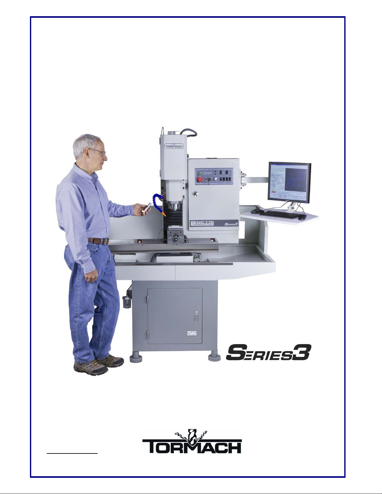
Using the Tormach
PCNC 770
Programmer’s and Operator’s Guide to the Personal CNC 770
Please email us at:
info@tormach.com
©2011 Tormach® LLC. All rights reserved.
Page 2

iiContents
Using Tormach PCNC 770 ii 32426 Rev C1-1
Page 3

Contents
1. Preface ............................................................................................. 1-1
1.1 Safety ............................................................................................................................... 1-1
1.1.1 Electrical Safety ................................................................................................................ 1-1
1.1.2 General Operating Safety .................................................................................................. 1-1
1.1.3 Safety Publications ........................................................................................................... 1-2
1.1.4 Safety Precautions............................................................................................................. 1-2
1.2 Personal CNC Concept ................................................................................................... 1-3
1.3 Performance Expectations .............................................................................................. 1-3
1.3.1 Cutting Ability .................................................................................................................. 1-3
1.3.2 Understanding Accuracy ................................................................................................... 1-4
1.3.3 Resolution, Accuracy and Repeatability of the PCNC ........................................................ 1-4
1.4 Scope and Intellectual Property...................................................................................... 1-4
1.5 Nomenclature .................................................................................................................. 1-5
2. Preparation ...................................................................................... 2-1
2.1 Planning for Your PCNC ................................................................................................ 2-1
2.1.1 Electrical Connection ........................................................................................................ 2-1
2.1.2 Location and Mounting ..................................................................................................... 2-1
2.1.3 Computer Mounting Arrangement ..................................................................................... 2-2
2.1.4 Learning and Training ....................................................................................................... 2-3
2.2 Receiving, Unpacking and Checking Shipment.............................................................. 2-4
2.2.1 Moving the Crate .............................................................................................................. 2-4
2.2.2 Uncrating and Inspection................................................................................................... 2-4
2.3 Mounting the PCNC ....................................................................................................... 2-4
2.3.1 Lifting onto Stand ............................................................................................................. 2-4
2.3.1.1 Lifting from Below ................................................................................................ 2-5
2.3.1.2 Lifting from Above ................................................................................................ 2-5
2.3.2 Fixing to Stand ................................................................................................................. 2-5
2.3.3 Installing central lubrication pump .................................................................................... 2-6
2.3.4 Accessories ....................................................................................................................... 2-6
2.4 Power to the PCNC ......................................................................................................... 2-6
2.5 Power for Machine Accessories ...................................................................................... 2-7
2.6 Tormach Machine Controller and Software Installation ............................................... 2-7
2.6.1 Control Computer ............................................................................................................. 2-7
2.6.2 Setting Up Your Controller ............................................................................................... 2-7
2.6.2.1 Positioning the Controller ....................................................................................... 2-7
2.6.2.2 Keyboard and Mouse ............................................................................................. 2-8
2.6.2.3 Display .................................................................................................................. 2-8
2.6.2.4 Speaker and Microphone Connections .................................................................... 2-8
2.6.2.5 Power Connections ................................................................................................ 2-8
2.6.3 Operating the Controller.................................................................................................... 2-8
2.6.3.1 About the Operating System ................................................................................... 2-8
2.6.3.2 Starting the controller ............................................................................................. 2-8
2.6.3.3 Stopping the controller ........................................................................................... 2-8
2.6.3.4 Mach3 License Installation ..................................................................................... 2-8
2.6.4 Machine Controller Maintenance and Configuration .......................................................... 2-9
2.6.4.1 Login and Software Installation .............................................................................. 2-9
Page 4

iiContents
2.7 Connecting and Running the PCNC ............................................................................... 2-9
2.7.1 Main Switch and Control Panel ......................................................................................... 2-9
2.7.2 Changing the Spindle Speed Range ................................................................................. 2-11
2.7.3 Computer Control of the Spindle and Coolant .................................................................. 2-12
2.7.4 MDI for Entering G- and M-code Commands .................................................................. 2-13
2.7.5 Jogging the Axes............................................................................................................. 2-13
2.8 Summary ....................................................................................................................... 2-14
3. Making Your First Part .................................................................... 3-1
3.1 Coordinates ..................................................................................................................... 3-1
3.1.1 Referencing the Machine................................................................................................... 3-1
3.2 Loading a Demonstration Program ................................................................................ 3-2
3.3 Running the Demonstration Part-program .................................................................... 3-3
3.3.1 Part Material ..................................................................................................................... 3-3
3.3.2 Setting Work Offsets ......................................................................................................... 3-3
3.3.3 Cutting in Air.................................................................................................................... 3-4
3.3.4 Cutting the Actual Part ...................................................................................................... 3-4
3.3.5 Summary .......................................................................................................................... 3-5
4. Routes from an Idea to a Part ........................................................ 4-1
4.1 Controlling the PCNC ..................................................................................................... 4-1
4.2 Choosing the Appropriate Design Software ................................................................... 4-2
4.3 Software for CAD/CAM ................................................................................................. 4-2
4.3.1 3D CAD ........................................................................................................................... 4-3
4.3.2 2D CAD ........................................................................................................................... 4-3
4.3.3 CAM ................................................................................................................................ 4-4
4.3.4 Running the G-code .......................................................................................................... 4-6
4.3.5 CAD/CAM Systems.......................................................................................................... 4-6
4.4 Programming with Wizards ........................................................................................... 4-9
4.4.1 Machining Wizard Concept ............................................................................................... 4-9
4.4.1.1 Selecting and Running a Wizard ............................................................................. 4-9
4.4.1.2 Standard Wizard Features ....................................................................................... 4-9
4.4.1.3 G-code from a Wizard .......................................................................................... 4-10
4.4.1.4 Commercial Wizards ............................................................................................ 4-10
5. Machine Controls ............................................................................ 5-1
5.1 Machine Operation ......................................................................................................... 5-1
5.1.1 Operator’s Panel ............................................................................................................... 5-1
5.1.2 Tool Changing .................................................................................................................. 5-3
5.1.2.1 Tooling Strategy .................................................................................................... 5-3
5.1.2.2 Changing R8 Tools ................................................................................................ 5-3
5.1.2.3 Changing TTS Tools .............................................................................................. 5-4
5.1.3 Spindle Speed Ranges ....................................................................................................... 5-4
5.2 Screen Control Panels ..................................................................................................... 5-5
5.2.1 Using the Screens ............................................................................................................. 5-5
5.2.2 Families of Related Controls ............................................................................................. 5-5
5.2.2.1 Screen Switching Controls ..................................................................................... 5-5
5.2.2.2 Axis Control Family ............................................................................................... 5-6
5.2.2.3 Jogging Control Family .......................................................................................... 5-7
5.2.2.4 Spindle Speed Control Family ................................................................................ 5-8
5.2.2.5 Feed Control Family .............................................................................................. 5-9
5.2.2.6 Program Running Control Family ......................................................................... 5-10
5.2.2.7 Toolpath Control Family ...................................................................................... 5-11
Using Tormach PCNC 770 ii 32426 Rev C1-1
Page 5

Contents
5.2.2.8 File Control Family .............................................................................................. 5-12
5.2.2.9 Work Offset and Tool Table Control Family ......................................................... 5-12
5.2.2.10 MDI and Teach Control Family ............................................................................ 5-12
5.2.2.11 Loop Control Family ............................................................................................ 5-13
5.2.2.12 Modes and Mode Alarm Control Family ............................................................... 5-13
5.2.2.13 Rotational Diameter Control Family ..................................................................... 5-13
5.2.2.14 Toolchange Position Control Family..................................................................... 5-14
5.2.2.15 Inhibits and Overrides Control Family .................................................................. 5-14
5.2.2.16 Feeds and Speeds Calculator ................................................................................ 5-14
5.2.2.17 Tapping Configuration Family.............................................................................. 5-15
5.2.2.18 Misc. Settings Control Family .............................................................................. 5-15
5.3 USB Jogging Pendants .................................................................................................. 5-16
5.3.1 Jog/Shuttle Controller ..................................................................................................... 5-16
5.3.2 Keypad Pendant .............................................................................................................. 5-16
6. Using Multiple Tools ....................................................................... 6-1
6.1 Offsets and Coordinate Systems ..................................................................................... 6-1
6.2 Tool Length Offsets and the Tool Table ......................................................................... 6-1
6.2.1 Example Operation of Multiple Tools ................................................................................ 6-1
6.2.1.1 To fill the table: ..................................................................................................... 6-2
6.2.1.2 Zeroing to work height ........................................................................................... 6-3
6.2.1.3 Using tool #2 ......................................................................................................... 6-4
6.2.1.4 Using other tools .................................................................................................... 6-4
6.2.1.5 Changing to a different work-piece ......................................................................... 6-4
6.2.2 How this multiple tooling setup works ............................................................................... 6-4
6.2.3 Programming, Buttons, or Direct Entry ............................................................................. 6-5
6.3 Alternative Methods Setting Up Tools ............................................................................ 6-6
6.3.1 Measuring techniques ....................................................................................................... 6-6
6.3.1.1 “Roll-Your-Own” Gauge Method ........................................................................... 6-7
6.3.1.2 Roller Gauge Method ............................................................................................. 6-7
6.3.1.3 Adjustable Parallel Method .................................................................................... 6-8
6.3.2 Comments on Accuracy .................................................................................................... 6-8
6.3.3 Working without the tool table .......................................................................................... 6-8
6.3.3.1 Direct Entry to Axis DRO ...................................................................................... 6-9
6.3.3.2 Using the Touch Buttons ........................................................................................ 6-9
6.3.4 Tool Table with General Tooling..................................................................................... 6-10
6.3.5 Tool table with the Tool Setter ........................................................................................ 6-10
6.4 Comments on Tool Offsets ............................................................................................ 6-10
6.5 Setting X and Y Offsets ................................................................................................. 6-11
6.5.1 By eye ............................................................................................................................ 6-11
6.5.2 With a Probe ................................................................................................................... 6-11
6.5.3 Measuring Off an Edge ................................................................................................... 6-11
6.5.4 Laser Centering Techniques ............................................................................................ 6-12
6.6 How Work Offsets work ............................................................................................... 6-12
6.7 Multiple Work Origins ................................................................................................. 6-14
6.7.1 G54 Work Offset ............................................................................................................ 6-14
6.7.2 Other Work Offsets ......................................................................................................... 6-14
6.8 Cutter Diameter Compensation .................................................................................... 6-15
6.8.1 CAD/CAM and Wizards ................................................................................................. 6-15
6.8.2 Concepts for Cutter Diameter/Radius Compensation........................................................ 6-15
6.8.3 Caveats in the Use of Cutter Compensation ..................................................................... 6-15
6.8.4 Examples of Operation .................................................................................................... 6-16
6.8.5 Look Ahead Issues .......................................................................................................... 6-19
6.8.6 Other Restrictions ........................................................................................................... 6-21
32426 Rev C1-1 iii Using Tormach PCNC 770
Page 6

ivContents
6.8.7 Perspective on Cutter Compensation ............................................................................... 6-21
6.8.8 Resources for Debugging Cutter Compensation ............................................................... 6-21
7. Part-programming Language Reference ....................................... 7-1
7.1 Definitions ....................................................................................................................... 7-1
7.1.1 Control Software ............................................................................................................... 7-1
7.1.2 Linear Axes ...................................................................................................................... 7-1
7.1.3 Rotational Axes ................................................................................................................ 7-1
7.1.4 Scaling Input..................................................................................................................... 7-1
7.1.5 Controlled Point ................................................................................................................ 7-2
7.1.6 Coordinated Linear Motion ............................................................................................... 7-2
7.1.7 Feed Rate.......................................................................................................................... 7-2
7.1.8 Arc Motion ....................................................................................................................... 7-2
7.1.9 Coolant ............................................................................................................................. 7-3
7.1.10 Dwell................................................................................................................................ 7-3
7.1.11 Units ................................................................................................................................. 7-3
7.1.12 Current Position ................................................................................................................ 7-3
7.1.13 Selected Plane ................................................................................................................... 7-3
7.1.14 Tool Table ........................................................................................................................ 7-3
7.1.15 Path Control Modes .......................................................................................................... 7-3
7.2 Interpreter Interaction with Controls ............................................................................ 7-4
7.2.1 Feed and Speed Override controls ..................................................................................... 7-4
7.2.2 Block Delete Control ........................................................................................................ 7-4
7.2.3 Optional Program Stop Control ......................................................................................... 7-4
7.3 Tool File .......................................................................................................................... 7-4
7.4 Part-programs Language ................................................................................................ 7-4
7.4.1 Overview .......................................................................................................................... 7-4
7.4.2 Parameters ........................................................................................................................ 7-5
7.4.3 Coordinate Systems .......................................................................................................... 7-5
7.5 Formatting Code Lines (Block) ...................................................................................... 7-5
7.5.1 Line Number..................................................................................................................... 7-6
7.5.2 Subroutine Labels ............................................................................................................. 7-7
7.5.3 Word ................................................................................................................................ 7-7
7.5.3.1 Number.................................................................................................................. 7-7
7.5.3.2 Parameter Value ..................................................................................................... 7-7
7.5.3.3 Expressions and Binary Operations ........................................................................ 7-8
7.5.3.4 Unary Operation Value .......................................................................................... 7-8
7.5.4 Parameter Setting .............................................................................................................. 7-8
7.5.5 Comments and Messages .................................................................................................. 7-9
7.5.6 Item Repeats ..................................................................................................................... 7-9
7.5.7 Item Order ........................................................................................................................ 7-9
7.5.8 Commands and Machine Modes ...................................................................................... 7-10
7.6 Modal Groups ............................................................................................................... 7-10
7.7 G-codes .......................................................................................................................... 7-11
7.7.1 Rapid Linear Motion – G00............................................................................................. 7-11
7.7.2 Linear Motion at Feed Rate – G01 ................................................................................... 7-13
7.7.3 Arc at Feed Rate – G02 and G03 ..................................................................................... 7-14
7.7.3.1 Radius Format Arc ............................................................................................... 7-15
7.7.3.2 Center Format Arc ............................................................................................... 7-16
7.7.4 Dwell – G04 ................................................................................................................... 7-17
7.7.5 Coordinate System Data Tool and Work Offset Tables – G10 .......................................... 7-17
7.7.6 Clockwise/Counterclockwise Circular Pocket – G12 and G13 .......................................... 7-18
7.7.7 Exit and Enter Polar Mode – G15 and G16 ...................................................................... 7-18
7.7.8 Plane Selection – G17, G18 and G19 ............................................................................... 7-19
7.7.9 Length Units – G20 and G21 ........................................................................................... 7-19
7.7.10 Return to Home – G28 and G30 ...................................................................................... 7-20
Using Tormach PCNC 770 iv 32426 Rev C1-1
Page 7

Contents
7.7.11 Reference Axes – G28.1.................................................................................................. 7-20
7.7.12 Straight Probe – G31 ....................................................................................................... 7-20
7.7.12.1 Straight Probe Command ..................................................................................... 7-20
7.7.12.2 Using the Straight Probe Command ...................................................................... 7-21
7.7.12.3 Example Code ...................................................................................................... 7-21
7.7.13 Cutter Radius Compensation – G40, G41 and G42 .......................................................... 7-22
7.7.14 Tool Length Offsets – G43, G44 and G49 ....................................................................... 7-23
7.7.15 Scale Factors – G50 and G51 .......................................................................................... 7-23
7.7.16 Temporary Coordinate System Offset – G52 ................................................................... 7-23
7.7.17 Move in Absolute Coordinates – G53 .............................................................................. 7-24
7.7.18 Select Work Offset Coordinate System – G54 to G59 & G59 P~...................................... 7-24
7.7.19 Set Path Control Mode – G61 and G64 ............................................................................ 7-25
7.7.20 Coordinate system rotation – G68 and G69 ...................................................................... 7-25
7.7.21 Canned Cycle – High Speed Peck Drill – G73 ................................................................. 7-25
7.7.22 Cancel Modal Motion – G80 ........................................................................................... 7-26
7.7.23 Canned Cycles – G81 to G89 .......................................................................................... 7-26
7.7.23.1 Preliminary and In-Between Motion ..................................................................... 7-27
7.7.23.2 G81 Cycle ............................................................................................................ 7-28
7.7.23.3 G82 Cycle ............................................................................................................ 7-29
7.7.23.4 G83 Cycle ............................................................................................................ 7-29
7.7.23.5 G85 Cycle ............................................................................................................ 7-30
7.7.23.6 G86 Cycle ............................................................................................................ 7-30
7.7.23.7 G88 Cycle ............................................................................................................ 7-30
7.7.23.8 G89 Cycle ............................................................................................................ 7-30
7.7.24 Distance Mode – G90 and G91 ........................................................................................ 7-30
7.7.25 G92 Offsets – G92, G92.1, G92.2 and G92.3 ................................................................... 7-31
7.7.26 Feed Rate Mode – G93, G94 and G95 ............................................................................. 7-31
7.7.27 Canned Cycle Return Level – G98 and G99 .................................................................... 7-32
7.8 Built-in M-codes ........................................................................................................... 7-32
7.8.1 Program Stopping and Ending – M0, M1, M2 and M30 ................................................... 7-32
7.8.2 Spindle Control – M3, M4 and M5 .................................................................................. 7-33
7.8.3 Tool change – M6 ........................................................................................................... 7-33
7.8.4 Coolant Control – M7, M8 and M9 ................................................................................. 7-34
7.8.5 Re-run from First Line – M47 ......................................................................................... 7-34
7.8.6 Override Control – M48 and M49 ................................................................................... 7-34
7.8.7 Call Subroutine – M98 .................................................................................................... 7-34
7.8.8 Return from Subroutine – M99 ........................................................................................ 7-34
7.9 Application Defined M-codes ........................................................................................ 7-34
7.9.1 Self-reversing Tapping Cycles......................................................................................... 7-34
7.9.2 Goto Toolchange Position – M998 .................................................................................. 7-35
7.9.3 User Defined M-codes .................................................................................................... 7-35
7.10 Other Input Codes ........................................................................................................ 7-35
7.10.1 Feed Rate – F .................................................................................................................. 7-35
7.10.2 Spindle Speed – S ........................................................................................................... 7-36
7.10.3 Select Tool – T ............................................................................................................... 7-36
7.11 Order of Execution ....................................................................................................... 7-36
7.12 Error Handling ............................................................................................................. 7-37
8. Machine Upgrades and Configuration........................................... 8-1
8.1 Fourth Axis – Rotary Table ............................................................................................ 8-1
8.1.1 Installing the Electronics ................................................................................................... 8-1
8.1.2 Utilizing the Fourth Axis ................................................................................................... 8-1
8.1.2.1 Referencing and Zeroing the Fourth Axis ............................................................... 8-1
8.1.2.2 Diameter Compensation Feature ............................................................................. 8-1
8.1.3 Fourth Axis Applications .................................................................................................. 8-1
8.1.3.1 Engraving on a Periphery of a Cylinder .................................................................. 8-2
32426 Rev C1-1 v Using Tormach PCNC 770
Page 8

viContents
8.1.3.2 Gear Cutting .......................................................................................................... 8-3
8.2 Probes (Active and Passive) and Tool Setters ................................................................. 8-3
8.2.1 Introduction to Uses of Probes and Tool Setters ................................................................. 8-3
8.2.2 Probing for Work/Tool Setting .......................................................................................... 8-4
8.2.2.1 Simple X/Y Probing ............................................................................................... 8-5
8.2.2.2 Z Probing ............................................................................................................... 8-7
8.2.2.3 Comprehensive X/Y Probing .................................................................................. 8-9
8.2.2.4 Probe Calibration ................................................................................................. 8-12
8.2.3 Digitizing parts from a model or for reverse engineering .................................................. 8-13
8.2.4 The Probe Electrical Interface ......................................................................................... 8-13
8.2.5 Other .............................................................................................................................. 8-14
8.3 Auto-reverse tapping .................................................................................................... 8-14
9. Specifications, Customization and Troubleshooting ................... 9-1
9.1 Intended Use Statement .................................................................................................. 9-1
9.2 Support............................................................................................................................ 9-1
• This manual – ALWAYS the first place to check!! ................................................. 9-1
• Related documents found at: http://www.tormach.com/documents.html .................. 9-1
• Our website at: www.tormach.com ......................................................................... 9-1
• Email to: info@tormach.com .................................................................................. 9-1
• Telephone Tormach at: 608-849-8381 .................................................................... 9-1
• Fax Tormach at: 209-885-4534............................................................................... 9-1
9.3 Outside of the Scope of Intended Use ............................................................................. 9-1
9.4 Specifications................................................................................................................... 9-2
9.4.1 Mechanical ....................................................................................................................... 9-2
9.4.2 Electrical .......................................................................................................................... 9-2
9.4.3 System .............................................................................................................................. 9-3
9.4.4 Options ............................................................................................................................. 9-3
9.5 Maintenance .................................................................................................................... 9-3
9.5.1 Foreword – Understanding Machine Design ...................................................................... 9-3
9.5.1.1 Machine Stiffness................................................................................................... 9-3
9.5.1.2 Backlash, Friction, and Lost Motion ....................................................................... 9-4
9.5.1.3 Factors Combine .................................................................................................... 9-4
9.5.1.4 Adjusting Geometry ............................................................................................... 9-4
9.5.1.5 Achieving Accuracy in Machining.......................................................................... 9-5
9.5.2 Protecting from Rust ......................................................................................................... 9-5
9.5.3 Gibs, Dovetail Slideways and Lubrication ......................................................................... 9-5
9.5.4 Way Covers ...................................................................................................................... 9-6
9.5.5 Axis Gib Adjustment ........................................................................................................ 9-6
9.5.6 Adjusting Ballscrew Preload ............................................................................................. 9-8
9.5.6.1 Understanding Preloaded Angular Contact Bearings ............................................... 9-9
9.5.6.2 Making the Adjustment .......................................................................................... 9-9
9.5.7 Adjusting Mating Surfaces .............................................................................................. 9-11
9.5.8 Speed Calibration............................................................................................................ 9-11
9.5.9 Using a Non-standard Printer Port ................................................................................... 9-13
9.5.10 Defining Your Own Sizes for Step-mode Jogging ............................................................ 9-14
9.5.11 Defining Probe Type ....................................................................................................... 9-15
9.5.12 Enabling 4th axis homing ................................................................................................ 9-15
9.5.13 Configuring to start in Metric units .................................................................................. 9-15
9.6 Troubleshooting ............................................................................................................ 9-16
9.6.1 Overview ........................................................................................................................ 9-16
9.6.2 Philosophy of Troubleshooting ........................................................................................ 9-16
9.6.3 Tips and Tools for Troubleshooting (Equipment and Procedures)..................................... 9-19
9.6.3.1 Safety .................................................................................................................. 9-19
9.6.3.2 Tip on Computer Diagnostics ............................................................................... 9-19
Using Tormach PCNC 770 vi 32426 Rev C1-1
Page 9

Contents
9.6.3.3 Tools ................................................................................................................... 9-20
9.6.3.4 Using the digital multi meter for electrical tests .................................................... 9-20
9.6.3.5 Contacting Technical Support............................................................................... 9-21
9.6.4 Frequently Found Problems (Repeat Offenders) .............................................................. 9-21
9.6.4.1 Loose Wires ......................................................................................................... 9-21
9.6.4.2 Wire Hairs ........................................................................................................... 9-22
9.6.4.3 Poor Cable Connections ....................................................................................... 9-22
9.6.4.4 Software Restart ................................................................................................... 9-22
9.6.4.5 Sensors (on the PCNC770 the End of Travel Sensors aka Limit Switches) ............ 9-22
9.6.4.6 Flaky Computer ................................................................................................... 9-22
9.6.4.7 Control Software license not installed ................................................................... 9-22
9.6.4.8 Unexplained stop or limit switch error while running ............................................ 9-23
9.6.5 Which sub-system should I troubleshoot .......................................................................... 9-23
9.6.5.1 Computer and Coolant Power Distribution Sub-system ......................................... 9-24
9.6.5.2 Control Power Sub-system Overview ................................................................... 9-26
9.6.5.3 9.6.5.3 Computer Control Communication Sub-Section ........................................ 9-29
9.6.5.4 Axes Drive Sub-system ........................................................................................ 9-31
9.6.5.5 Spindle Drive Sub-system .................................................................................... 9-46
9.7 Mechanical maintenance.............................................................................................. 9-56
9.8 Electrical maintenance .................................................................................................. 9-56
9.9 Preparation for Transport ............................................................................................ 9-57
9.10 Disassembly for Transport ........................................................................................... 9-57
10. Appendices .................................................................................... 10-1
10.1 Appendix 1 – Not Used.................................................................................................. 10-1
10.2 Appendix 2 – Exploded Parts Views ............................................................................. 10-1
10.3 Appendix 3 - Use of a Standard PC to control PCNC ................................................ 10-14
10.3.1 Choice of computer ....................................................................................................... 10-14
10.3.2 Optimizing the Windows Installation............................................................................. 10-15
10.3.3 Installing the Control Software ...................................................................................... 10-15
10.3.3.1 Installing .............................................................................................................10-15
10.3.3.2 Vital Re-boot ......................................................................................................10-16
10.3.3.3 Testing the Installation ........................................................................................10-16
10.3.3.4 DriverTest After a Software Crash .......................................................................10-17
10.3.3.5 Manual Driver Installation and Un-installation.....................................................10-17
10.3.4 Optimization of Windows XP ....................................................................................... 10-18
10.3.4.1 Remove Unnecessary Services and Startup Programs...........................................10-19
10.3.4.2 Disable Power Management ................................................................................10-19
10.3.4.3 Disable sound card ..............................................................................................10-19
10.3.4.4 Disable Automatic Updates .................................................................................10-20
10.3.4.5 Set Computer to Standard PC not ACPI PC .........................................................10-20
10.4 Revision history ........................................................................................................... 10-21
11. Index .................................................................................................. 23
32426 Rev C1-1 vii Using Tormach PCNC 770
Page 10

Page 11

1. Preface
1.1 Safety
Any machine tool is potentially dangerous. Computer controlled machines are potentially more
dangerous than manual ones because, for example, a computer is quite prepared to plunge a 3"
diameter facing cutter at 50 inches per minute into a block of high-carbon steel or to mill the
clamps off your table.
1.1.1 Electrical Safety
The PCNC 770 can deliver sufficient force to break brittle tools, to crush bones and to tear
flesh.
This manual tries to give you guidance on safety precautions and techniques but because we do
not know the details of your workshop or other local conditions we can accept no responsibility
for the performance of the machine or any damage or injury caused by its use. It is your
responsibility to ensure that you understand the implications of what you are doing and to
comply with any legislation and codes of practice applicable to your country or state.
Power Input: The PCNC 770 supply is 115 VAC. A circuit rated at 20 amps is required. This
power supply can provide lethal electrical shocks. The power input should be unplugged before
working in the electrical cabinet.
Preface
Grounding: The power input must be grounded. During installation it is not enough to assume
that the ground line of a wall outlet is properly grounded. Check continuity between the
machine frame and true earth ground (water pipe or similar) to ensure a good ground
connection.
A Ground Fault Interrupt or GFI (i.e., Residual Current Circuit Breaker or RCCB in Europe)
outlet is not recommended as the filters in the spindle drive can give leakage currents sufficient
to trip a normal 30 mA breaker.
Electrical Panel: NEVER operate the machine tool with the cabinet door open. NEVER allow
a coolant pump to operate with the cabinet door open. DO NOT allow the coolant system to
flow coolant directly at the cabinet door seal or on the operator console controls. Neither the
cabinet door seal nor the electrical controls are sealed against liquids.
Retained Electrical Power: Electronic devices within the electrical cabinet may retain
dangerous electrical voltages after the power has been removed.
Electrical Service: Certain service and troubleshooting operations require access to the
electrical cabinet while the electrical power is on. Only qualified electrical technicians should
perform such operations.
1.1.2 General Operating Safety
Safe operation of the machine depends on its proper use and the precautions taken by each
operator.
Read and understand this manual. Be certain every operator understands the operation and
safety requirements of this machine before operating the machine.
Always wear safety glasses and safety shoes.
Always stop the spindle and check to ensure the CNC control is in the stop mode before
changing or adjusting the belt/pulley position, tool or work piece.
32426 Rev C1-1 1-1 Using Tormach PCNC 770
Page 12

Preface
Never wear rings, watches, gloves, long sleeves, neckties, jewelry or other loose items when
operating or working around the machine. Long hair should be bound or kept under a hat.
Use adequate safeguarding around the operating envelope. It is the responsibility of the
employer to provide and ensure point of operation safeguarding per OSHA 1910.212 – Milling
Machine.
1.1.3
1.1.4
Safety Publications
Tormach recommends the following publications for assistance in enhancing the safe use of
this machine.
• Safety Requirements for The Construction, Care and Use of Drilling, Milling and Boring
Machines (ANSI B11.8-1983). Available from The American National Standards
Institute, 1430 Broadway, New York, New York 10018.
• Concepts and Techniques of Machine Safeguarding (OSHA Publication Number 3067).
Available from The Publication Office – O.S.H.A., U.S. Department of Labor, 200
Constitution Avenue, NW, Washington, DC 20210.
Safety Precautions
1. Do not run this machine without knowing the function of every control key, button, knob or
handle. Refer to the manual or contact Tormach if any function is not understood.
2. Protect your eyes. Wear approved safety glasses (with side shields) at all times. You should
never use compressed air to remove chips or to clean the machine. An air blast will often
launch a metal chip into a place it should not be.
3. Ear protection should be used on any operations that exceed sound levels of 85dBa.
4. Avoid moving parts. Before operating this machine remove all jewellery including watches
and rings, neckties and any loose-fitting clothing.
5. Keep your hair away from moving parts.
6. Take off gloves before you operate the machine. Gloves are easily caught in moving parts
or cutting tools.
7. Never operate with unbalanced tooling or spindle fixtures.
8. Remove all tools (wrenches, chuck keys, etc.) from the spindle and machine surface before
you begin. Loose items can become dangerous flying projectiles.
9. Use adequate work clamping. Do not allow your work piece to become a projectile.
10. Never operate a milling machine after consuming alcoholic beverages or taking strong
medication.
11. Protect your hands. Stop the machine spindle and ensure that the computer control is
stopped before you:
• Change tools;
• Change parts or adjust the work piece;
• Change the belt/pulley position;
• Clear away chips, oil or coolant – always use a chip scraper or brush;
• Make an adjustment to the part, fixture, coolant nozzle or take measurements;
• Remove protective shields or safeguards – do not reach for the part, tool or fixture around
a guard.
12. Keep work area well lit. Ask for additional light if needed.
13. Keep the computer area clear of clutter. Recognize that machine motion can occur when
certain keys are pressed. Objects falling on the keyboard can result in unexpected motion.
14. Avoid getting pinched in places where the table, saddle or spindle head create “pinch
points” while in motion.
Using Tormach PCNC 770 1-2 32426 Rev C1-1
Page 13

15. Securely clamp the work piece in a vise, on the table or in the fixture. Use proper holding
clamping attachments and position them clear of the toolpath. Be aware of larger pieces that
will be cut free during operations – loose parts can become projectiles.
16. Always use proper feeds and speeds, as well as depth and width of cut, to prevent tool
breakage.
17. Use proper cutting tools for the job.
18. Do not use dull or damaged cutting tools. They break easily and become dangerous
projectiles. Never use longer or larger tools than necessary.
19. Chips and dust from certain materials (e.g., magnesium) can be flammable. Fine dust from
normally non-flammable materials can be flammable or even explosive.
20. Chips and dust from certain materials can be toxic. Vapours from certain overheated
materials can be toxic. Always check a Materials Safety Data Sheet (MSDS) of suspect
materials. Refuse machining work requests of unknown materials.
21. If you are in any doubt you must seek guidance from a professionally qualified expert
rather than risk injury to yourself or to others.
1.2 Personal CNC Concept
The PCNC 770 is a machine tool intended to make CNC machining more personal. As with the
evolution of personal computers, the evolution of personal CNC alters the paradigm of what a
machine tool is about. We aim for a machine tool so affordable that anyone can have one.
We feel that the work of engineers, inventors, technicians, hobbyists, educators and others will
be enhanced when they have access to CNC machinery. In education, each student can run his
own machine instead of waiting in line when the machine tool costs less than 20% of a small
machining center. In R & D, turn-around on prototype design takes minutes instead of days
when a machine is “at the ready” and on site. In general engineering, designs sent to the
production machine shop are improved when the design engineer has been more involved in the
prototype creation.
Preface
The PCNC offers the precision of a production machine but with cost/performance optimized
for short run operation.
1.3 Performance Expectations
1.3.1 Cutting Ability
The machine is capable of cutting most materials at or near their recommended feeds and
speeds. For example, for fast metal removal on 6061 aluminium we will run a 1/2" diameter 2
flute cutter at around 18 IPM (inches per minute) and 3000 RPM, using a full 1/2" depth of cut.;
that is a pretty good volumetric rate of metal removal so it is essential to clear chips with a
flood coolant. We will run smaller cutters when we are not trying to remove large amounts in a
hurry. For most aluminium work we use 3/8". The example above, using a 1/2" cutter, results in a
surface speed of 390 SFM (surface feed per minute), a 1/4" cutter needs 6000 RPM to get the
same surface speed, well within the performance envelope of the machine.
Cutting steel and iron needs a lower volumetric rate, thus slower feed and speed. The PCNC
will run best using smaller cutters when working with tougher materials. For example, the
general machining recommendation for some oil hardening steels is 30 SFM. Doing this with a
¾" end mill, the surface speed calculation indicates 150 RPM, but that is below the minimum
spindle speed of the PCNC 770 and certainly at minimum speed limited power is available. By
switching to a 1/4" end mill the recommended spindle speed becomes 460 RPM, well within the
capability of the PCNC. By keeping close to general machining recommendations your tools
will last longer and you will have a better cut.
32426 Rev C1-1 1-3 Using Tormach PCNC 770
Page 14

Preface
1.3.2 Understanding Accuracy
While a machine tool may seem absolutely rigid, the truth of the matter is that everything has
some elasticity. Related to elasticity is the compressibility of components such as ball nuts and
bearings. Preloading of bearings and ballscrews can remove the physical open space between
moving parts, but the technique cannot eliminate compressibility. The key to achieving
maximum accuracy is understanding and controlling the magnitude and direction of forces.
Maximum accuracy is achieved when the forces are minimized, as occurs in a finishing cut.
Maximum repeatability is achieved when the forces are repeatable, both in magnitude and
direction.
1.3.3 Resolution, Accuracy and Repeatability of the PCNC
The minimum discrete position move is 0.0001", this is the resolution of motion. Machine
accuracy is closely related to ballscrew accuracy. Our ballscrews are accurate to 0.0006" per
foot, but considering all the other factors that come into play, we prefer to keep accuracy
expectations to 0.0013" per foot. Repeatability will be better than 0.001" per foot.
Machining is a mix of science, skill and art. The caveat in stating accuracy and repeatability is
that these factors depend on the techniques used by the machinist. A skilled machinist can often
deliver accuracy that exceeds the accuracy specified by the machine builder, while an
inexperienced machinist may have difficulty delivering the expected accuracy. With this
understanding, we cannot tell you what accuracy you will be able to achieve in your own work.
Nevertheless, the accuracy specified by a machine builder remains an important reference
point.
1.4 Scope and Intellectual Property
This document is intended to provide sufficient information and detail to allow you to install,
setup and use your Tormach mill. It assumes that you have appropriate experience and/or
access to training for any Computer Aided Design/Manufacture software that you intend to use
with the machine. This document also assumes familiarity with typical Microsoft Windows
applications programs as the control software for the PCNC runs under the Windows operating
system.
Tormach LLC is dedicated to continual improvement of its products, so suggestions for
enhancements, corrections and clarifications will be gratefully received.
Tormach LLC, Art Fenerty and John Prentice assert their right to be identified as the authors of
this work. This work is copyrighted by Tormach LLC. The right to make copies of this manual
is granted solely for the purpose of training courses related to, evaluation of and/or use of the
PCNC. It is not permitted, under this right, for third parties to charge for copies of this manual
beyond the cost of printing.
Every effort has been made to make this manual as complete and as accurate as possible but no
warranty or fitness is claimed or implied. All information provided is on an “as is” basis. The
authors, publisher, and Tormach LLC shall not have any liability for, or responsibility to, any
person or entity for any reason for any loss or damage arising from the information contained in
this manual.
Tormach, PCNC1100 Personal CNC, PCNC770 Personal CNC, and Tormach Tooling System
are registered trademarks of Tormach. Windows XP and Windows 7 are registered trademarks
of Microsoft Corporation. If other trademarks are used in this manual, but not acknowledged,
please notify Tormach LLC so this can be remedied in subsequent editions.
Tormach milling machines and accessories are covered by one or more of the following U.S.
Patents: 7,386,362, D606,568, D612,406, D621,859 and Patent(s) Pending.
Using Tormach PCNC 770 1-4 32426 Rev C1-1
Page 15

1.5 Nomenclature
This manual uses the following typographical nomenclature:
Software control
Refers to a Control Software “soft” control. (i.e., a Windows control on the PC screen).
Hardware Control
Refers to a physical button or switch on the Operator’s Panel of the machine.
G-code (e.g., G01X34.8)
Used to show G-code programs.
Key name (e.g., Enter)
Tells you to press the indicated key.
Preface
32426 Rev C1-1 1-5 Using Tormach PCNC 770
Page 16

Page 17
2. Preparation
This chapter describes the work required to unpack and to commission the
hardware and software of the PCNC.
It contains a lot of detail but can be completed in one or two hours by a person
familiar with CNC machines. Enough detail is given here so that a beginner
should be successful but some users may prefer to arrange for a machine tool
expert to do this work.
If your machine has already been set-up then you can skip this chapter
2.1 Planning for Your PCNC
2.1.1 Electrical Connection
The PCNC 770 is shipped with a 3-wire cord and no electrical plug. There are several different
NEMA (National Electric Manufacturers Association) and non-NEMA plug patterns that can be
used. Straight blade patterns are common in household use; twist-lock patterns are more
common in industrial locations. Power required is 115 to 130 VAC, 50 or 60 Hz. Continuous
current is below 15 amps, but a 20 amp breaker or slow blow fuse is recommended.
Preparation
The power input must be grounded. During installation it is not enough to assume that the
ground line of a wall outlet is properly grounded. Check continuity between the machine frame
and true earth ground (water pipe or similar) to ensure a good ground connection.
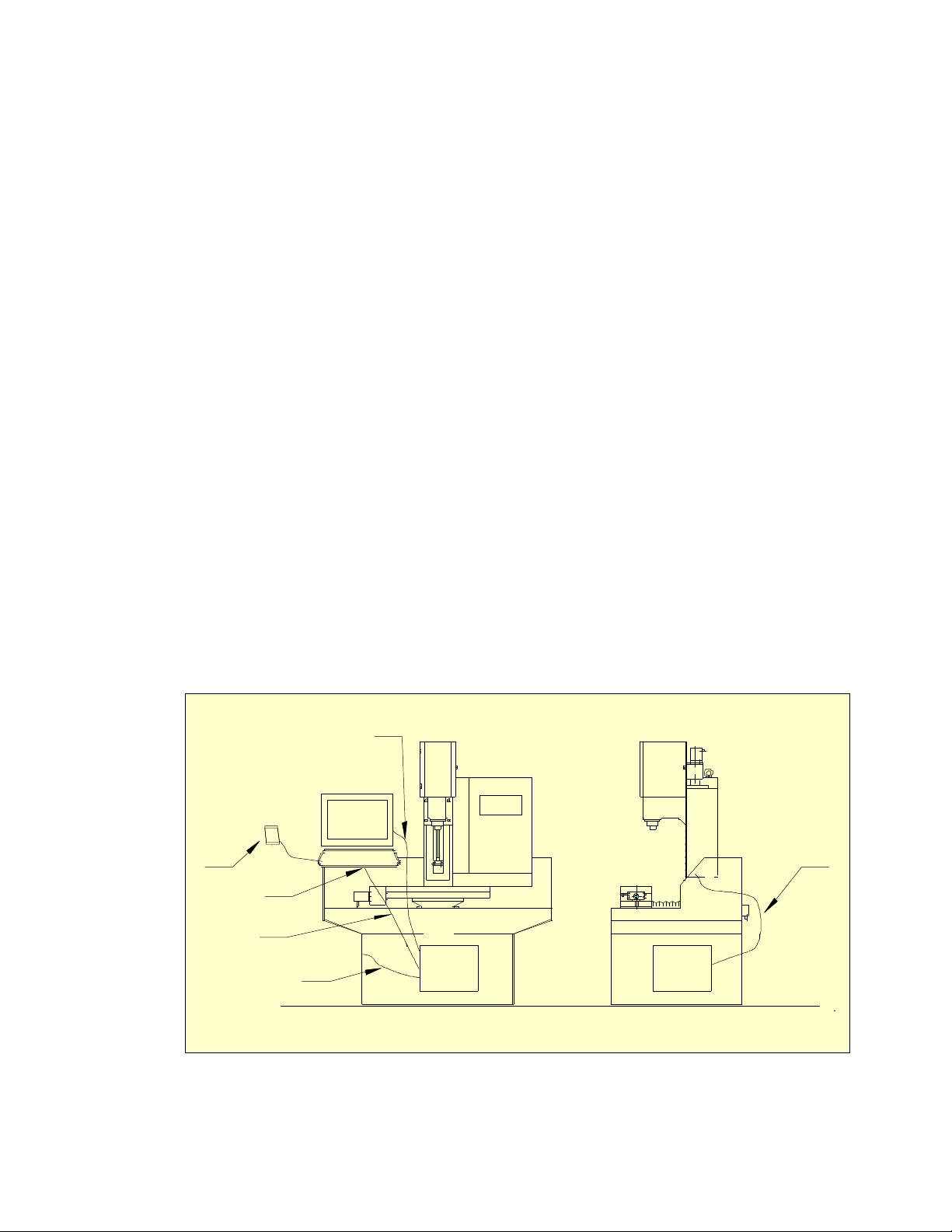
2.1.2 Location and Mounting
People experienced with CNC machining will undoubtedly have ideas as to how they want to
setup their PCNC (figure 2.1). While the machine can be configured in many different ways,
there are a few limitations. Many fully enclosed vertical machining centers incorporate high
volume coolant systems that make the inside of the machine look like the inside of a
dishwasher. The PCNC electrical
cabinet and operator console should
not be exposed to such conditions.
Additionally, there should never be
an enclosure or accessory that limits
access to the emergency stop. Please
keep these limitations in mind when
you plan your configuration.
If your prior experience is limited to
manual mills then keep in mind that,
as CNC dramatically extends your
machining capabilities, it will also
change the way you cut metal. When
your metal cutting is done by turning
handles on a manual mill your
operations will generally be limited to
cleaning up a surface, drilling a hole
pattern or cutting to a dimensional
outline. With manual milling many
people are accustom to dry cutting, clearing chips with a small brush as they go.
Figure 2.1 – An example mounting on stand
32426 Rev C1-1 2-1 Using Tormach PCNC 770
Page 18
Preparation
With CNC you have a whole new world open to you. In many cases you may turn the majority
of the stock into chips, cutting a shape out of a solid block of metal the way Michelangelo
would cut a sculpture from a block of marble. Unless you are limiting yourself to cutting cast
iron, wood, printed circuit boards or certain other materials, you will probably want a coolant
system on your machine. Mist coolant can be effective for keeping your cutting tools cool, but
it does little for clearing chips. Flood coolant will cool the cutting tools while clearing chips,
but is more challenging to contain. We strongly recommend that you plan your setup with a full
motion tray and splash guards, such that coolant will be captured as it overflows the machine
table within the full operating envelope of the machine.
Another reason to use a full motion tray is to reserve the space that will be required when the
machine moves. If you use a narrow drip tray or none at all, you should plan for full machine
motion plus some human space when you place the machine in your workshop. You do not
want to locate it where you can create crush points between the machine table and a wall. When
in operation, the X, Y and Z motions will not stop when they hit something. The machine will
move with hundreds of pounds of force, enough to punch through a wall, tip over the machine
or crush someone in the way.
Machine safety is the responsibility of the operator. This includes all aspects of safety: setup,
location, operation, security and all other factors that involve safety.
The PCNC 770 requires a minimum plan area of 60" wide by 40" deep. This gives clearance for
the full motion of the table and for minimal access for cabling etc. The overall height required
is 73" assuming that it is installed with the table at a working height of 36".
Tormach offers a suitable heavy duty stand with built in storage for tooling and the control
computer. It is also available with a coolant sub-system.
You should choose a well lit location and provide any additional task-lighting to make it easy to
setup work on the table.
Over time you will find that you accumulate a range of tools and tool holders so you should
allocate space for storage of these near the machine. A rack with numbered slots is convenient
to avoid errors when doing tool changes during a job.
5
USB jogging
pendant
4
LCD
Screen
Keyboard
6
3
2
1
Personal
computer
Personal
computer
Figure 2.2 Computor and Display
2.1.3 Computer Mounting Arrangement
Keep the computer in a clean location, preferably inside the stand of the milling machine.
Resist the temptation to expose the computer in any way. Providing access to floppy disks, CDs
Using Tormach PCNC 770 2-2 32426 Rev C1-1
Page 19

Preparation
or direct computer controls will also open the computer to contamination and risk. Tormach
offers accessories that will allow you to operate the system without exposing your computer.
While there are many possible configurations for your machine control computer, we suggest
the following (figure 2.2):
1. USB bulkhead (panel mount) cable. This allows you to mount a USB socket directly on the
side of the cabinet. You can use a standard USB flash drive to transfer G-code programs
and other files to the machine controller. This is Tormach PN 30278 (USB bulkhead mount
cable – 3' Version 2.0 USB A to A extension M-F).
2. USB extension cable, extending the short cable normally found on keyboards and other
USB devices. Tormach PN 30279 (10FT USB 2.0 A to A Male/Female Extension Cable).
3. USB mini-keyboard. This is about the size of most laptop keyboards. The keyboard
includes a key which will power down the computer, allowing a convenient way to
shutdown the system. This is Tormach PN 31371 (Mini Keyboard). The keyboard can be
protected against coolant or chips by addition of Keyboard Cover PN 31384.
4. A Tormach USB jogging pendent is a very useful accessory for jogging, manual operations
and machine setup. Two options are available: a key based pendant (Tormach PN 30214
Pendent, 10 key USB keypad) and a jog/shuttle controller pendant that gives very fine
control of jogging speeds and distances. (Tormach PN 30616 Jog/Shuttle Controller).
5. LCD monitor signal cables are normally too short. Most inexpensive VGA signal extension
cables create serious signal degradation. This is particularly true with Super VGA screen
resolutions. Tormach PN 30280 (10FT SVGA Super VGA M/F Monitor Cable w/ ferrites)
is designed to extend Super VGA signals without degradation.
6. This is simply the AC power cord of the computer. The Computer switch on the operator
console controls a convenience outlet on the bottom of the machine control cabinet. If you
set the BIOS/CMOS configuration in your computer to start the computer when it sees AC
power then the console switch will allow you to start the computer from the console. You
should not shut off the computer from this switch due to issues with the Microsoft
Windows operating system, but you can turn the computer on from the keyboard/screen
controls.
There are several important points to bear in mind when using devices interfaced with USB
(Universal Serial Bus).
Do not attempt to run a G-code program that is stored on a USB drive (often called pen drives,
memory stocks, flash drives). Copy your G-code files into a folder on the hard drive (usually C:
of the control computer. Remove the USB drive after making the copy.
Do not use external USB hubs or devices like monitors or keyboards containing hubs.
USB devices can be affected by electrical noise on the computer mains power line. Devices
with large motors like compressors and ‘shop vacuum cleaners should not be plugged in to a
multiple outlet used by the control computer.
These rules minimize the chance of Windows deciding to manage USB devices when you are
running cuts on the mill.
The milling machine itself requires a 115 volt single phase wall power outlet rated at 20 amps.
2.1.4 Learning and Training
The final element of planning your installation is to consider the training that you and any other
users of the machine will need.
This manual will give you the basic information required to start manufacturing components
with you PCNC. You must, however, expect to have to invest time in learning how to achieve
the best results. The areas which you will find easy and those which will require more effort
will of course depend on your background; you might be most comfortable with machining or
with component design or even with information technology.
32426 Rev C1-1 2-3 Using Tormach PCNC 770
Page 20
Preparation
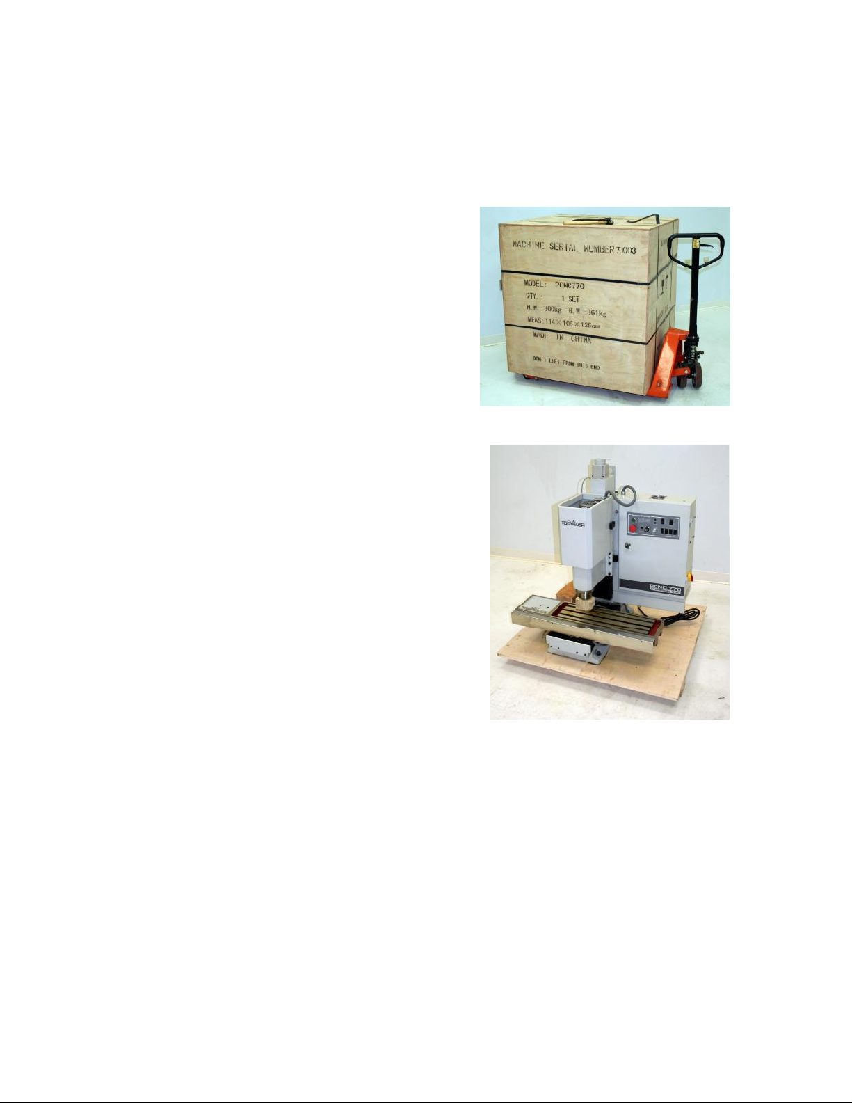
Figure 2.4
– Un-crated machine on pallet
We believe that you will find it highly cost-effective to acquire additional training materials for
areas of CAD/CAM/CNC which are new to you. Tormach sales can help point you in
appropriate directions.
2.2 Receiving, Unpacking and Checking Shipment
2.2.1 Moving the Crate
The PCNC is supplied on a standard pallet and
can be offloaded from a truck with a tailgate
lift and moved on smooth surfaces using a
hydraulic pallet jack. This makes delivery very
economical (figure 2.3).
Remove the crate top and sides with care as
the axis drive stepper motors are in vulnerable
places (figure 2.4).
The crated system weighs less than 800 lbs
(400 kg) nevertheless, it requires mechanical
handling to move it over rough ground. The
machine is designed to be modular so it can be
dismantled to move through small doorways
or along narrow corridors and has an optional
moving kit (Part number 31333) to facilitate this.
Some mechanical handling equipment will be
needed to lift it onto the stand. Tormach advises
you to employ the services of a specialist rigger if
the machine has to be moved in situations where
the pallet lifter cannot be used or where there is
no crane to lift the machine onto its stand. It is
possible to improvise using a small trailer, a
portable engine crane and similar tools if there is
no alternative but this risks injury to you and
damage to the machine.
Figure 2.3 – Crated machine as delivered
2.2.2 Uncrating and Inspection
After uncrating you should check the contents
against the parts listed on the packing slip and
inspect the machine for any damage incurred
during transit so any claims can be made within the carrier’s deadline.
2.3 Mounting the PCNC
2.3.1 Lifting onto Stand
The machine can be lifted onto an operating stand by either of two methods: from below using
the base connection points or from above using a slinging technique. In either case caution and
common sense are needed for the protection of the machine and the people involved. Lifting up
to 600 lbs can be simple with proper preparation and good equipment, but it is never trivial and
the dangers involved should be taken seriously.
The work of lifting and placing heavy equipment is called rigging. If you are not trained or
prepared then you should seek the advice of those who are. Professional riggers can be found in
most areas.
Using Tormach PCNC 770 2-4 32426 Rev C1-1
Page 21
2.3.1.1 Lifting from Below
The base of the machine has four 7/8" diameter holes. By sliding two steel bars into these holes,
at least 32" in length, you end up with some outrigger wings that can be used in combination
with a fork lift truck to lift the machine. These should be solid steel bars, not pipes and be ¾" or
7
/
" in diameter.
8
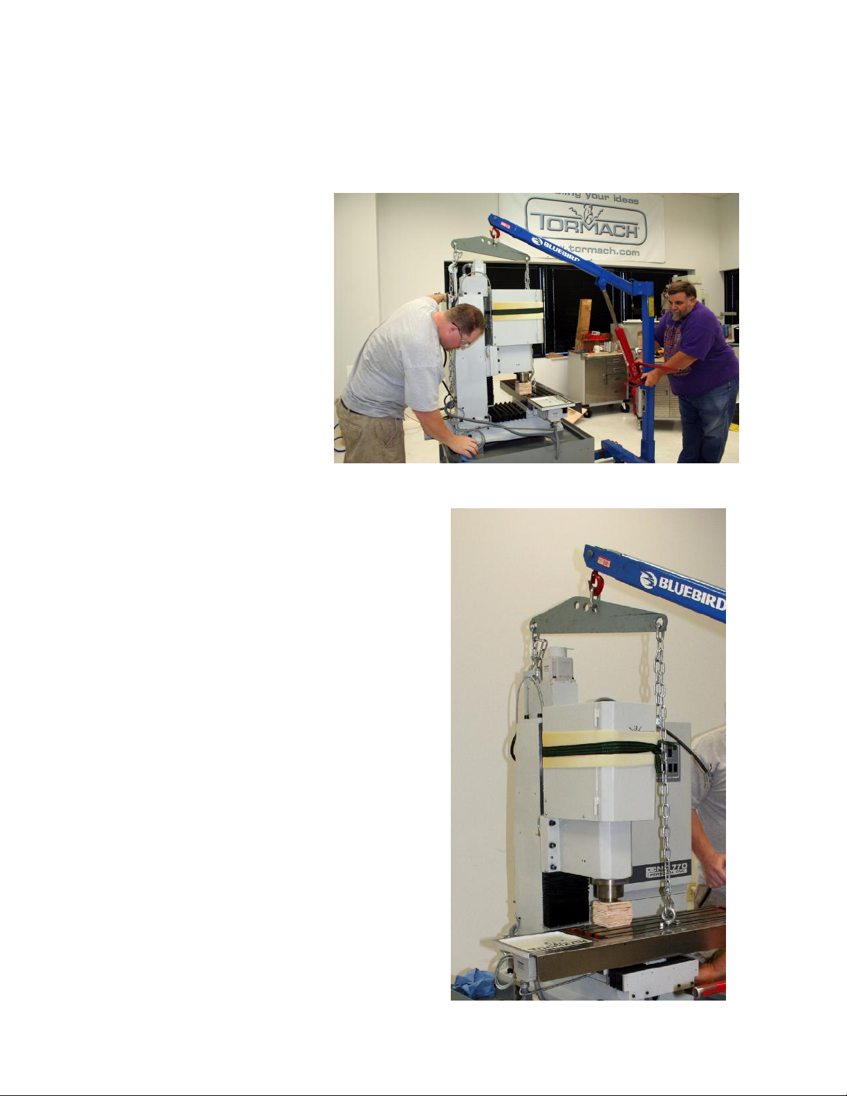
2.3.1.2 Lifting from Above
The alternative way to
mount your PCNC to a
stand involves lifting
from above. The eye in
the top of the column is
suitable for lifting the
machine, but it is not in
line with the center of
gravity. The machine
will tilt when lifted
solely from the eye. The
alternative is to sling the
machine using a
combination of the eye
and an eye in a T-nut on
the table using a
Tormach special tool
(part number 30576 -
Machine Hoist Bar) (figure 2.5).
Preparation
Figure 2.5 – Hoist bar for slinging the mill
Figure 2.6 shows the geometry of the
slinging. The table should be as far away
from the column and as far to the right as
possible to optimize the balance.
It is most important that the machine is not
lifted by the control cabinet or by any of the
protruding stepper motors or the head or the
table. Incorrect rigging of the sling will
likely result in serious damage to the
PCNC.
The optimal balance for lifting should be
checked with the machine an inch or two
off the floor.
The X-, Y- and Z-axes can easily be moved
by hand if the covers on their coupling
boxes are removed. The smooth (i.e.,
outside face) of an old auto engine timing
belt or poly-vee auxiliary drive belt, which
has been cut to make a strip, can be used to
turn the coupling between the stepper motor
and ball screw (figure 2.7).
When you are ready to lift the machine you
should remove the nuts from the four
screws holding it down to the pallet.
2.3.2 Fixing to Stand
Figure 2.6 – Slinging geometry
Unlike very large mills, the level of your
32426 Rev C1-1 2-5 Using Tormach PCNC 770
Page 22
Preparation
mill does not significantly alter machine accuracy. Leveling should be sufficient to provide
proper coolant drainage, but precision leveling is not necessary.
The supports under the corners of the base of the mill are important to machine accuracy.
Despite the apparent stiffness of the base casting, it will respond to the weight of the machine.
The result will be errors in the left/right tram of the mill. For best accuracy, add shims under the
left front or right front corners of the machine as needed, such that the left/right tram is within
your desired tolerance. Something like
0.002” is usually all that is needed;
however it is certainly possible to do
even better.
A welded steel stand is unlikely to be
flat. Furthermore, if it is flat sitting on
its own, it will sag down as the 800 lb
machine is placed on it. Be aware that
welded steel stands are neither stress
relieved nor as stiff as the machine base
itself. If, for example, you place a
0.050” shim between the base of the
mill and the stand, you’re not actually
lifting the corner of the base up by
0.050”. It is more likely that you are moving the mill up by 0.005” and the corresponding point
on the stand down by 0.045”.
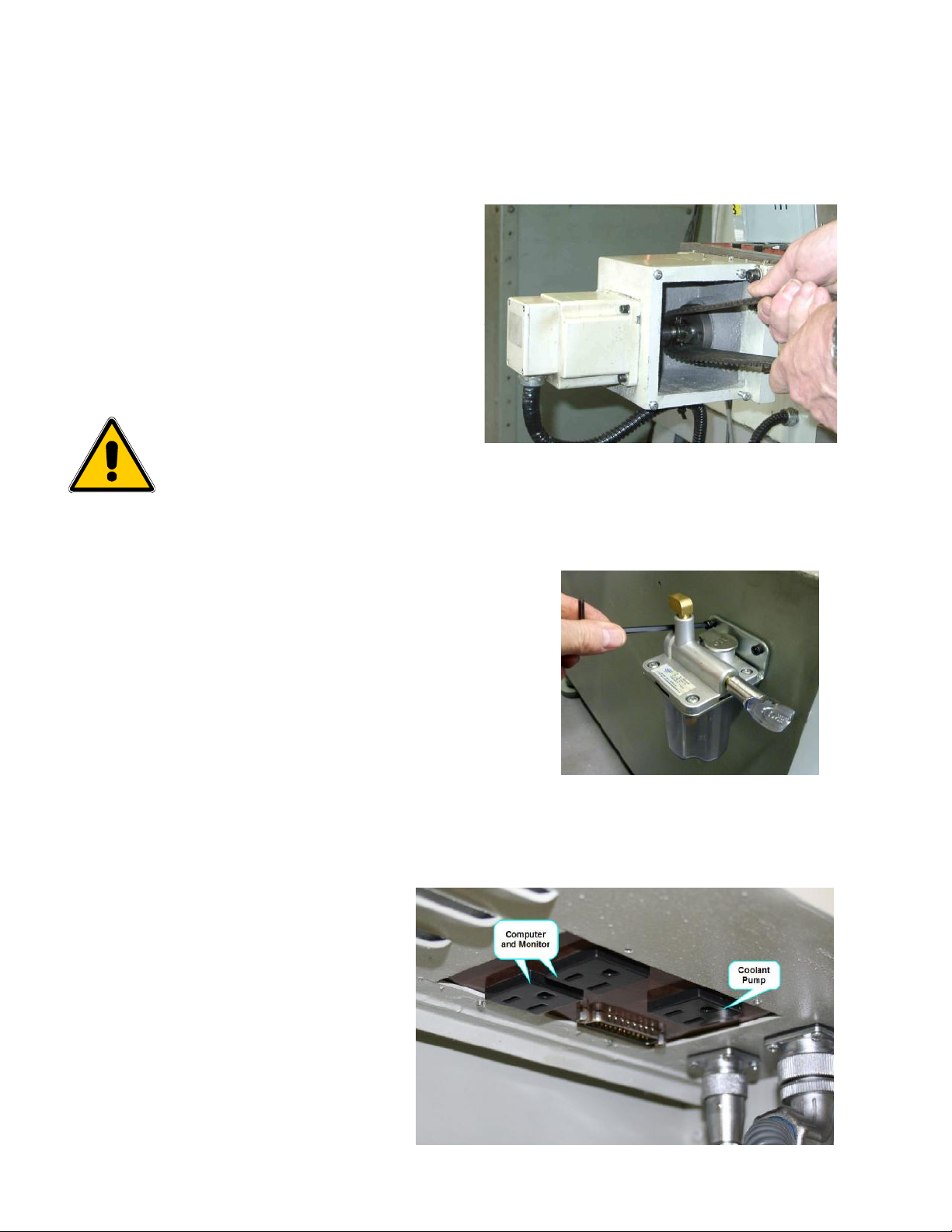
2.3.3 Installing central lubrication pump
The standard pump is manually operated. An
optional automatic pump is available. It comes with
its own installation instructions.
The manual pump is fixed by the two socket screws
provided to tapped holes on the left hand side of the
stand. You may find that your pump mount bracket
is oriented backwards.
Simply remove the 4 screws connecting the bracket
to the pump and rotate the bracket 180 deg.
Connect the lube pipe to the elbow on the pump
and fill it with suitable clean way lubrication oil.
2.3.4 Accessories
You should now try out the
positioning of the screen,
computer and coolant subsystem, if any.
2.4 Power to the PCNC
Figure 2.8 – Fitting manual oiler
The PCNC 770 is powered by
115 volt single phase AC (50
or 60 Hz). The computer,
monitor and coolant pump
should all be specified for 115
volt operation..
The main machine power lead
is shipped with a US style
Using Tormach PCNC 770 2-6 32426 Rev C1-1
Figure 2.9 – Power outlets
Page 23
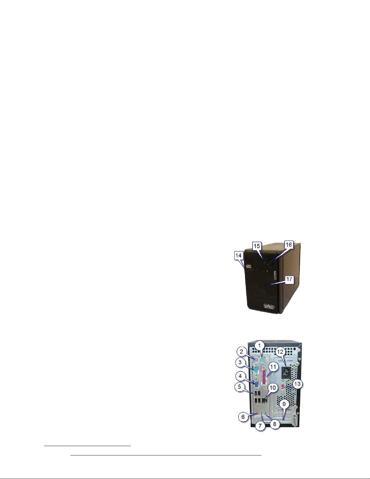
Preparation
plug. Should you need to change this please note that the wire color code is Black = Hot (Live),
White = Neutral and Green = protective ground.
2.5 Power for Machine Accessories
The 115 VAC outlet under the control cabinet that is nearest to the column feeds the coolant
pump and is controlled by the CNC software and panel switch. The pair of similar outlets
further from the column is switched by the Computer switch on the front panel.
2.6 Tormach Machine Controller and Software Installation
2.6.1 Control Computer
We recommend that you purchase a Tormach Machine Controller as part of the mill package.
Tormach Machine Controllers include MachOS, an implementation of Microsoft Windows
Embedded which was developed by Tormach to avoid the problems frequently seen with
configurations based on Windows XP, Vista, or 7 . The Machine Controller is available as
either a Basic and Performance model. Because of the high spindle and axis speeds possible,
we recommend using the Performance model.
If, in exceptional circumstances, you wish to provide your own computer, it needs to run the 32
bit (x86) version of Microsoft Windows XP (Home or Professional edition) or Microsoft
Windows 7. Our experience is that the more modern and high performance the motherboard in
your computer is, the less reliable the performance running a real-time task will be. This is due
to many power saving and temperature control tricks used by the chip manufacturers. The
Tormach Machine Controller is specifically designed for real-time applications.
Details of the computer requirements and software installation for a standard PC can be found
in Appendix 3.
2.6.2 Setting Up Your Controller
2.6.2.1 Positioning the Controller
The controller should be positioned where it will
remain clean and dry. It can be placed vertically or
horizontally. When vertical it should be resting on the
rubber pads. When horizontal it should be resting such
that the CDROM drive is above, with the power button
on the lower right corner.
Do not allow anything to block the vented cabinet
holes. The steel cabinets design for PCNC series mills
have storage sections intended for the controller. The
cabinet storage areas are large enough to provide
adequate cooling without the need for additional fans.
The controller remains well protected in the machine
stand, but access to the controller is less inconvenient.
This isn't a concern if you power the controller through
the computer outlet on the PCNC mill (see the section
below Operating the Controller: Starting the
Controller) and if you extend the USB ports using USB
Bulkhead Cable (PN 302781) which positions a USB
port to the outside of the machine stand.
Figure 2.10 – Front of TMC
1
Refer to http://www.tormach.com/document_library/DS30278_USBBulkheadCable.pdf
32426 Rev C1-1 2-7 Using Tormach PCNC 770
Figure 2.11 – Rear of TMC
Page 24

Preparation
2.6.2.2 Keyboard and Mouse
The controller supports with USB (figure 2.11 - sockets at 5) or PS/2 style mouse and keyboard
connections (sockets 1 & 2). Wireless keyboards and mice are not recommended. Both
powered and passive USB hubs have a history of problems when used in combination with
Mach3 software. We recommend that all USB devices plug directly into the USB ports on the
controller (sockets 5).
2.6.2.3 Display
Connect the display to socket 4 - figure 2.11.
2.6.2.4 Speaker and Microphone Connections
Speaker and microphone connections are possible but not recommended.
2.6.2.5 Power Connections
Check the voltage setting before connecting power (figure 2.11 – location 13). The controller
can be set to run on either 115 VAC or 230 VAC and will operate equally well on 50 or 60 Hz
power.
2.6.3 Operating the Controller
2.6.3.1 About the Operating System
The MachOS operating system is built with Microsoft Embedded Standard, but it looks and acts
much like Windows XP Pro. If you are familiar with Windows XP, then you know how to use
MachOS. The Tormach Machine Controller has s been designed and configured to work with
Mach CNC control software. Under most circumstances, no modification to the configuration
is needed. Modification to the configuration of the operating system can disable the controller.
2.6.3.2 Starting the controller
The Controller is configured to boot immediately upon the application of power. This allows
you to turn on the computer using a remote power switch, such as the power switch marked
COMPUTER on the front of the PCNC mill control panel. You can also start the controller
using the power button on the front panel. For the present just power the Controller and your
monitor from a wall outlet.
PCNC control software (Mach3) will start immediately after the Controller boots. If you need
to exit the control program you can restart it using the desktop icon.
2.6.3.3 Stopping the controller
The controller should be stopped by clicking on the Start > Shutdown function on the lower left
corner of the computer screen. It is not a good idea to simply turn off the controller, it should
be allowed to shutdown properly.
After you have shutdown the computer, turn off the computer power using the switch on the
front panel of the mill. This will allow you to use the power switch to turn the computer back
on. If you forget to turn off the power then you will not be able to turn it on using a quick offon cycle of the computer power switch. The computer needs to be off for 30 seconds before the
function of "Boot upon Power" will work.
2.6.3.4 Mach3 License Installation
Important Note: The controller is shipped without the Mach3 license on its hard drive. The
Mach3 control program installed, but without the license it will only work in demo mode (limit
500 lines of code) without the Mach3 license. Tormach ships the Mach3 software license on
a separate CD. To install you license file, simply insert the license CD after the controller has
Using Tormach PCNC 770 2-8 32426 Rev C1-1
Page 25

Preparation
booted up. The license file will automatically be transferred to the hard drive. You can then
remove the license CD and store it in a safe location.
2.6.4 Machine Controller Maintenance and Configuration
2.6.4.1 Login and Software Installation
The controller boots up to an automatic login with Username: Operator and a blank
password. The Operator has rights to use the software but cannot install software or modify the
MachOS configuration. If you need to install software or modify configuration you must
logout Operator and login again with:
Username: Administrator
Password: administrator
Note that the upper/lower case is important. The Administrator login will be necessary if you
need to reinstall the PCNC software or install new software.
The controller is licensed as a dedicated machine controller. Do not attempt to use it as a
desktop computer and do not try to install general purpose software such as Microsoft Office or
Microsoft Word. You can install CNC related software such as CAD, CAM, or machining
utility programs such as Machinist's ToolBox although Tormach does not recommend this..
2.7 Connecting and Running the PCNC
You have now completed the installation and merely need to connect the PCNC to the
computer.
Now close down MachOS and switch off the Controller. Connect the parallel port of the
computer (figure 2.11 socket 11) to the D25 connector on the underside of the PCNC control
cabinet. The cable provided to connect the computer to the mill meets IEEE 1284
specifications. This provides a high level of immunity to electrical noise, which is important to
reliable operation. Do not use inferior cables.
Now power the Controller from the outlet near the D25 connector and if relevant, power the
monitor from the connector adjacent to it below the PCNC control cabinet. Viewed from
behind, the inlet is on the right next to two outlets for computer and monitor. The coolant pump
outlet is to the left of these (figure 2.9).
2.7.1 Main Switch and Control Panel
The rotary main switch on the right hand side of the control cabinet disconnects the mains
power from the PCNC itself and isolates computer/coolant outlets that are on the bottom of the
cabinet.
Warning: You should not open the control cabinet until the mains power to the machine and to
the computer/coolant pump are both removed from the wall outlet. Live parts may be exposed
even when the main switch is in the off position.
Computer On/Off
Warning: The following power-up and power-down sequences should be followed exactly to
avoid the risk of unintended machine motion which could cause injury to you or damage to the
machine.
32426 Rev C1-1 2-9 Using Tormach PCNC 770
Page 26
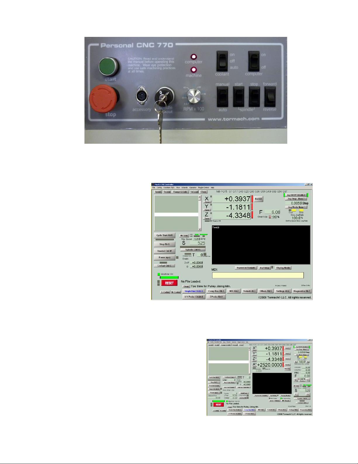
Preparation
Switch the main switch ON and switch the computer power on at the PCNC control panel
Figure 2.12 – Control panel layout
(figure 2.12).
The computer will power up and run the Control Program (figure 2.13).
This will allow you to
perform all the important
functions on the standard
machine. If you have the 4th
axis or want to use G-code
features like Optional Stop
then you may wish to use
the Comprehensive Run
screen (figure 2.14). In this
case click the Comp Run
button to change the
display.
The screen “Light Emitting
Diodes” (LEDs in this
manual) by the Reset button
will be flashing as will the
Machine OK LED.
Now, returning to the operator’s panel:
Start and EStop
The Start button will energize the circuits for
the axis drives and for the spindle motor. The
Stop button stops all motion and is the
Emergency Stop (EStop) control. The Stop
button locks in the off position once it has been
pressed as safety feature. It can be released by a
turning the button-head a quarter-turn clockwise.
Note: Once the stop button has been pressed the
start button is inoperative until the stop button is
released.
The Machine LED indicates that the Start
button has been pressed. When it is lit then the
Machine OK LED on the computer screen should be solid green. If this does not happen then
Figure 2.13 – Simple main screen
Figure 2.14 – Comprehensive Run screen
Using Tormach PCNC 770 2-10 32426 Rev C1-1
Page 27
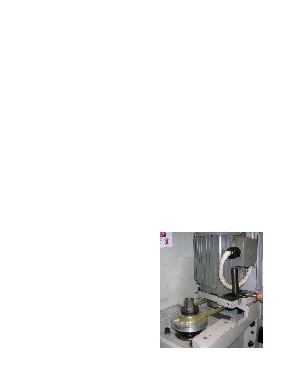
Spindle
Preparation
you should check that the cable between the PCNC and computer is fully plugged-in at both
ends. You will be able to test some controls on the PCNC, even if the LED does not give the
correct indication but you will have to find the fault before you can move the PCNC axes under
computer control.
An important safety interlock is that the rotation of the spindle can be disabled (while
maintaining axis drive power) by the Spindle Lockout key-switch. The switch on the
spindle drive door performs the same function. These are used to ensure that the spindle cannot
start when an R8 tool holder is being changed (door open) or when a tool is being changed in a
collet chuck. Turning the Spindle Lockout key or opening the spindle cover while the
spindle is running will also stop the spindle. Stopping the spindle in that way will not damage
any components, but it is generally a poor practice.
The controls to the right of the key-switch are all concerned with manual control of the spindle.
If the Manual/Auto switch is in the Auto position then none of the other spindle controls have
any effect. In the Manual position the computer control of the spindle is disabled.
Switch to Manual and turn the speed control knob fully counterclockwise. Press the Spindle
Start rocker. The spindle should start turning slowly in the clockwise (forward) or
counterclockwise (Reverse) direction (viewed from above) depending on the setting of the
Forward/Reverse switch. You can safely switch directions while the spindle is turning.
Try changing the speed using the rotary control knob. The actual speed will depend upon which
of the two pulley ratios you have selected.
Pressing the Spindle Stop rocker will halt the spindle.
Coolant
The Coolant switch controls the power to the coolant pump outlet on the underside of the
control cabinet. In the Off position the outlet is not powered and the pump will not run. In the
On position power is applied to the outlet and the pump will run until the switch is switched to
either off or auto positions. In the Auto position outlet power is under program control the
pump will run if the Control Program
requests coolant.
Accessory Socket
The Accessory socket is for connection of
accessories such as a touch probe. See
Chapter 8 for details of the interface.
2.7.2 Changing the Spindle Speed Range
The PCNC 770 has two speed ranges. The
low range, 175 to 3,250 RPM, is suitable
for most machining operations with ferrous
and other tough materials. The high range,
525 to 10,020 RPM is suitable for small
diameter cutters, plastics and non-ferrous
materials. The range change is performed
by moving the multi-vee belt from the
upper pair of pulleys (high speed range) to
the lower pair (low speed range).
Figure 2.15 – Changing spindle pulley setting
Open the spindle drive door. The interlock
will prevent the motor from running. Note:
32426 Rev C1-1 2-11 Using Tormach PCNC 770
Page 28
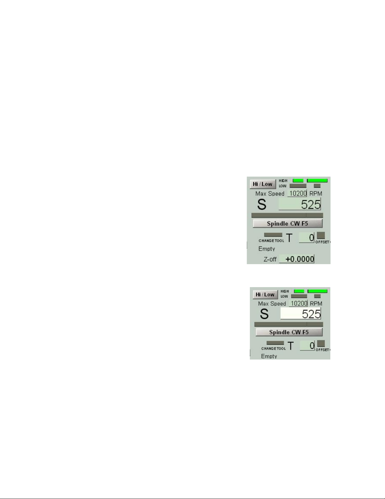
Preparation
Opening the spindle drive door will also stop a running spindle; however, this is a safety hazard
and should not be used as a substitute for stopping the spindle with the spindle controls in the
Control Software. Use the included wrench to loosen the motor mounting plate and the front
handle to pull the motor forward. The belt will slacken and can be moved from one set of
pulleys to the other (figure 2.15).
For the following tests, select the low speed range by placing the belt on the lower pair of
pulleys). Retighten the belt so there is between 1/8" and ¼" movement between the pulleys, lock
the motor mounting and stow the handles in the vertical position.
2.7.3 Computer Control of the Spindle and Coolant
Switch the Spindle and Coolant to Auto on the control panel. Make sure the computer is
displaying the Simple Run screen as shown in figure 2.13. The portion shown in figure 2.16
shows the controls for the spindle.
Use the mouse to click the Hi/Lo button. You will see that the screen LEDs depicting the
pulleys will change and the appropriate maximum speed will be displayed below them. Choose
the Low setting to correspond to the PCNC pulleys.
Note: Just after starting the system the screen LEDs may
not correspond to the indicated maximum speed. The
speed value is always correct and a click on the Hi/Lo
button will bring the LEDs into step.
Next to the label S, is a digital read-out (DRO) of the
requested spindle speed. You can change this by clicking
the mouse on it. It will become highlighted. Type a
number, say 525 (for 525 rpm) and press Enter. Figure
2.17 shows the screen just before pressing Enter. If you
make a mistake you can press Esc to return to the original
value.
This technique is used for setting any DRO. Remember to
Figure 2.16 – Spindle controls
use Enter after any DRO change. If you forget and just
click on another DRO, then any value you have just entered
will be discarded. This is designed to avoid accidental
changes.
Now check that the machine is safe and that the motor door
is closed and click on the Spindle CW F5 button. The
spindle will start running. Clicking the button again will
stop it.
The F5 in the caption tells you that function key F5 is a
“shortcut” to this button; it can also be used to start and stop
the spindle.
Figure 2.17 – Setting S word
Notice that there are two sets of screen LEDs. The outer set
indicates that the machine is dwelling to ensure the spindle has started and fully stopped. The
center LED indicates that it is running.
If you have connected a coolant pump to the outlet under the control box (see vacant outlet in
figure 2.9) then you will be able to control it by the Coolant Ctrl-C button or its shortcut which
is the Ctrl-C key. Beware of the position of the coolant nozzle before you try this!
Using Tormach PCNC 770 2-12 32426 Rev C1-1
Page 29
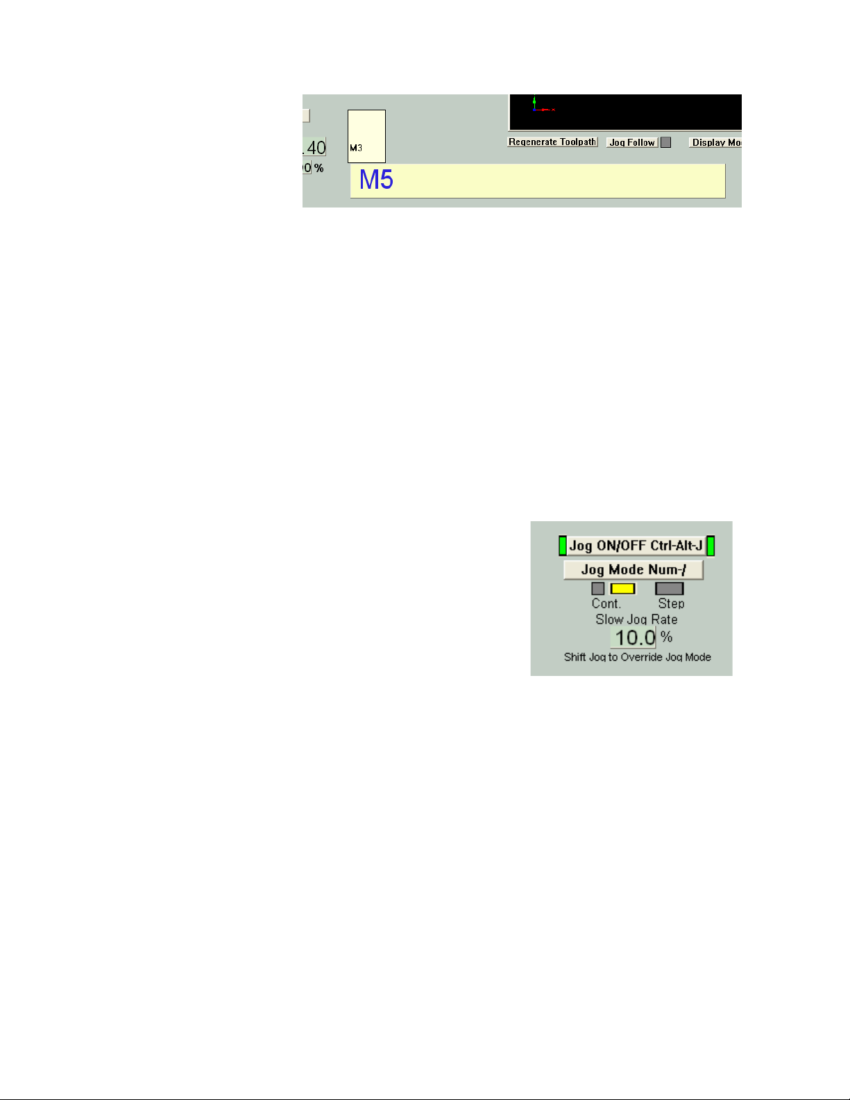
Preparation
2.7.4 MDI for Entering G- and M-code Commands
When you are
making parts the
commands to the
machine (G- and
M-codes) will
generally be read
from a file. It is
however often
convenient to
command the
PCNC directly. This can be done by typing command into the Manual Data Input (or MDI for
short) line.
The command to start the spindle in the clockwise direction is M3 and the command to stop it is
M5.
Click the mouse in the bar marked MDI. It will highlight. You type the command in the
highlighted line. Unlike in DROs, the Backspace, Del, Left and Right arrow keys are available
to help you correct any typing errors.
When you press Enter the command will be executed. Pressing Esc abandons it and closes the
MDI line. You can try starting and stopping the spindle with M3 and M5 G-codes.
Figure 2.18 – MDI Line in use
Notice that the recent commands are displayed in a fly-out box. You can choose one of these to
copy into the MDI line using the Up and Down arrow keys.
Figure 2.18 shows the MDI line after the spindle has been started (M3) and the M5 has been
typed but not yet executed by Enter.
There are some handy features of the MDI box. It can be
opened by pressing Enter (rather than needing a mouse
click). It stays open after a command has been executed.
It can be closed by Enter when it is blank.
Note: All keystrokes go to the MDI when it is open so it
is not possible to execute shortcuts or jog the axes. If the
keyboard does not do what you expect then you
probably still have the MDI line open.
2.7.5 Jogging the Axes
The final thing to try before actually making your first part is to move (jog) the PCNC axes
using the keyboard.
There are several options for jogging which will be explained in detail below. The jogging
controls are at the top right hand side of the screen (figure 2.19).
Click the Jog ON/OFF button (or use its shortcut Ctrl-Alt-J) to turn on the screen LEDs beside
it if they are not already on. Click Jog Mode (or use its shortcut) to turn on the larger of the
LEDs above the word Cont (for Continuous jogging). Type the value 10 into the Slow Jog Rate
DRO; do not forget the Enter to accept the value)
Figure 2.19 – Simple jog controls
In the next steps you may find the directions of movement are unexpected. Therefore, when you
use the arrow keys you should be prepared to quickly release the key if the axes moves in an
unexpected direction or is near its limit of travel. Now, press the Left, Right, Up and Down
arrows on the keyboard. The table will move while you hold the key down. If you crash into the
limit switches then the LED beside the red Reset button will flash and the machine will stop.
Click on Reset and very carefully jog the other way. Take care not to mechanically hit the limit
doing this in the wrong direction. You will lose the referenced status if you trip a limit switch.
32426 Rev C1-1 2-13 Using Tormach PCNC 770
Page 30
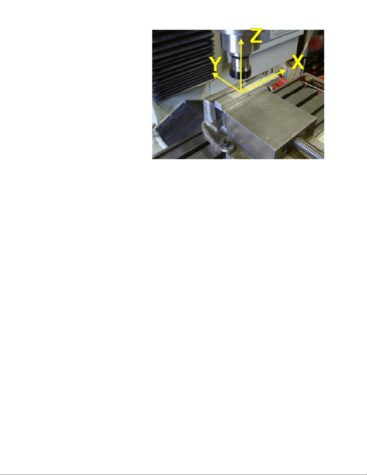
Preparation
You might find the
directions of movement are
unexpected. Figure 2.20
shows the tool above a
work piece. The positive X,
Y and Z directions are
marked by arrows. If you
press the Right arrow key
then the tool will move in
the positive X direction
(i.e., to the right of the
work). Similarly the Up
arrow moves the tool in the
positive Y direction (i.e.,
towards the PCNC
column). Of course, this
actually happens on the
PCNC by the table moving
under the tool but you must
Figure 2.20 – Jogging is to move the tool relative to work
imagine what it would look
like if you were sitting on the table and watching the tool.
You should jog around until you are quite confident which way the machine moves when you
press any key. Notice that the values in the Axis DROs change as you jog the tool around.
Jogging the Z-axis is done by using the Page up and Page down keys. Here of course it is the
tool that moves, so “Up” is indeed up.
2.8 Summary
This chapter has covered a lot of basic ground. Much of it only has to be done once. You may
however wish to revisit the latter parts if you are not fully confident with using buttons, DROs,
the MDI and jogging. We will give less detail on using these (e.g., assume you know about
shortcuts and when to use Enter) in subsequent chapters.
Using Tormach PCNC 770 2-14 32426 Rev C1-1
Page 31

Making your first part
3. Making Your First Part
This chapter shows you how to make your first part with the PCNC. It assumes
that you have no prior experience with running a part-program on a Computer
Numerically Controlled machine tool.
Even if you have previous experience you will find that following this tutorial
gives you an introduction to the controls of the machine.
3.1 Coordinates
Coordinates are simply how you describe where the tool is positioned. We assume that you
have the computer and PCNC setup and switched on and are looking at the Simple screen.
3.1.1 Referencing the Machine
You have seen that jogging the machine moves the tool and this changes the numbers in the X-,
Y- and Z-axis DROs. You may have wondered where these numbers come from and indeed
doubted that they are very sensible. The answer is that they are probably meaningless. The
computer has no way of knowing yet where the tool or table is positioned.
Referencing is the process which puts the
machine in a known mechanical position
and sets the corresponding axis DROs.
The known position is where the limit
switches operate with Z at the top of the
column and the spindle over the top lefthand corner of the table. This position is
called Home and so these limit switches
are called the Home switches. Their
operation is very obvious on the Z-axis. A
software trick makes the X and Y
arrangement slightly harder to understand but this is of no importance at present.
Figure 3.1 shows how the DROs might look when you start up the system. They have arbitrary
values in them and the three screen LEDs are red.
Check that the LEDs by the red Reset button are not flashing and that nothing is in the way of
movement of the table and head of the
PCNC. Click the Ref All button.
The Z-axis will first move up to the top of
the column, stop at the switch and then
move down a fraction. The Z DRO will be
set to zero and its LED turn to green. This
will be followed by the same action with X
and Y. Be wary the first time you do this
and if an axis does not stop at its switch
you must hit the EStop button on the
PCNC control panel and look at the
Maintenance/Troubleshooting section of this manual (figure 3.2).
Figure 3.1 – The axis DROS un-referenced
Figure 3.2 – Referenced and ready to use
Note: It is helpful to reference the PCNC before using it. This allows the working envelop in X
and Y to be shown on the tool path display and helps avoid running into the limit switches or,
worse, the tool attempting to cut into the vise or table. The Control Program tries to protect you
32426 Rev C1-1 3-1 Using Tormach PCNC 770
Page 32

Making your first part
from this sort of trouble but intentionally leaves the responsibility of referencing to you. You
can repeat the referencing operation at any time if you have reason to suspect that the PCNC is
in the wrong position (e.g., an error in a depth of cut has stalled the machine).
Despite the advantages of having the machine referenced, you can still use it without reference,
for example if one of the home switches fails or becomes unreliable. We advise you to treat this
as a crippled mode for use until you can get the switch fixed. The Goto toolchange position
macro M999 and G28 will not work if the machine is not homed but you can ignore the error
message and jog the axes by hand to get clearance to change the tool. The home reference
procedure is how the machine learns where it is within its own framework and that knowledge
is essential to execute M998 and G28.
The accuracy of the limit switches is subject to contamination by dried up coolant, the presence
of chips, and other factors. Consider the work offsets to be approximate only and do not
depend on the automated reference procedure for your most accurate work. For maximum
accuracy, you should touch off in X, Y, and Z after referencing and before proceeding to cut.
The Control Software now knows exactly where the PCNC axes are and has called this home
position X = 0.0, Y = 0.0 and Z = 0.0. You probably think that this position is not very
convenient and you are correct. The Control Software will let you define any other place to be
0, 0, 0 when you are running a part-program but will always keep a record of the machine
position using home as machine zero.
Normally the axis DROs will show your
coordinates for the position but you can
see the Control Software machine
coordinates by clicking the Machine
Coords button. A big flashing LED warns
you that you are not looking at your
version of the coordinates.
3.2 Loading a Demonstration Program
The system comes with a demonstration
program in the file
C:\PCNC3\GCode\FirstPart.nc
Run the Control Software and make
sure the screen LEDs by Reset button
are not flashing and that the axes are
referenced.
Click the OpenG button. You will be
given a Windows open file dialog.
Navigate to the G-code folder and open
the file (figure 3.3).
You will see the code of the program
in the window at the left of the screen
and the path that the tool will take in
the toolpath display. Use the mouse to
drag with the left-hand button in the
toolpath display to rotate the display. It
behaves as if it is drawn inside a clear
ball and the mouse turns the ball.
Figure 3.3 – File opening
Figure 3.4 – The drawing for FirstPart
So that you understand what is going to
happen we should look at the way this file was produced using a Computer Aided Design/
Computer Aided Manufacturing (CAD/CAM) program. The PCNC will produce parts designed
Using Tormach PCNC 770 3-2 32426 Rev C1-1
Page 33

Making your first part
in any available industry standard tools. Tormach offers a number of powerful, yet reasonably
priced software tools, some of which are used as examples in this manual.
The original drawing is shown in figure 3.4. It consists of the characters “PCNC” and an
irregular quadrilateral.
Having drawn the outline of the
part, we defined the material from
which it will be cut, the size of tool
to cut the letters ( ¼") , the depth of
the letters, the size of tool to cut the
recess (½") and the depth of the
recess. The program automatically
creates the part-program (G- and
M-codes) to make the part and can
display a visualization of the
finished work (figure 3.5). We will
discuss the options which you have
for designing your own parts in the
next chapter.
You should now be able to relate
the toolpath display to the part
Figure 3.5 – CAD/CAM Visualization of finished part
illustrated
3.3 Running the Demonstration Part-program
3.3.1 Part Material
We suggest that you use a free-cutting
material to make this first part. MDF,
birch ply or, as we used, resin
impregnated ply are all suitable. You
need a piece at least ½" thick and 7"
by 4". Clamp this securely to the
PCNC table. For many jobs it is worth
putting a layer of scrap material under
the work. This will protect the table
when through holes are to be cut and
may save damage in the event of a
mistake in the part program or in
operating the machine.
Put a ¼" diameter tool into a tool holder in the
spindle. Ensure the lower spindle pulleys are
selected on the machine and are set on the screen
using the Hi/Lo button.
Use masking tape to indicate a 5" length near the
middle. This length must be clear of the clamps.
Figure 3.6 – Tool setup at zero points
3.3.2 Setting Work Offsets
Jog the axes so that the tool is just above the
material at the top left-hand corner of the 5"
Figure 3.7 – Toolpath during a cut
section (figure 3.6).
We suggest that you do a dummy run cutting in the air so jog the Z-axis up about two inches.
32426 Rev C1-1 3-3 Using Tormach PCNC 770
Page 34

Now click in the X-, Y- and Z-axis DROs, in turn and type the value 0 into each of them. Do
not forget to press Enter to accept the values. The reason for doing this is that you want the
position of the tool (i.e., at the top left of your material and an inch above it) to be X = 0, Y = 0
and Z = 0. The Control Software still refers to the home switches as zero internally but lets you
have your own separate coordinate system for the work. If you click the Machine Coords button
then you will be shown how your zero relates to the home position. The difference between the
machine coordinates and your coordinates is called the Work Offset.
Note: We are going to cut this part by giving you a "recipe". You will learn why and how it
works later. Please don't add anything extra to the recipe. Adding yeast to a soda bread recipe
makes a fine mess. For example, here, you should have the length of each tool in the tool table
still set to zero.
You are now ready to run the program.
3.3.3 Cutting in Air
Click the Cycle Start button. The PCNC will start running
but almost immediately ask for tool number 1. This is
already loaded so just click Cycle Start again. The
machine will trace the letters PCNC in the air. It does this
four times because they are to be cut 0.2" deep and the
program is designed only to cut 0.05" each time. This is
conservative but runs no risk of breaking the ¼" diameter
tool.
Making your first part
The toolpath shows the tool as it moves by a different
colored line (figure 3.7).
After “cutting” the letters the machine will stop and ask for tool number 2. Jog the Z-axis up a
few inches so you can put the ½" cutter into the tool holder. Then jog down to about 2" above
the material, and type the value 0 into the Z DRO. Do not forget to press Enter to accept the
value.
Now click Cycle Start
again. The machine will
use a spiral path to cut out
the recess (called a pocket).
3.3.4 Cutting the Actual Part
You should now be ready
to actually cut the part.
Jog the Z-axis and swap
back to the ¼" tool. You
must now set this so it is
just touching the surface of
your material and define
this as Z = 0. There are
many good ways of doing
this and we will look at them in a later chapter. For now you just need a thin sheet of paper or
perhaps a plastic wrapper from a candy packet.
Figure 3.8 – Touching a tool
Figure 3.9 – Cutting the text
Jog the Z-axis down to ¼" or so above the material. If you are using keyboard jogging, change
the Slow Jog % DRO from 10% to 2%. The Tormach Jog/Shuttle Controller allows you to
control the speed depending on how far you turn the ring.
Using Tormach PCNC 770 3-4 32426 Rev C1-1
Page 35

Making your first part
Then with the paper below the tool, carefully jog down until the paper just gets trapped by the
tool. You must avoid ramming the tool into the material; you want to just touch the paper
(figure 3.8).
When in position type 0 and Enter into the Z-axis DRO. You now have the Work Offsets set to
suit your material thickness and length of tool.
Make certain you have properly shut the door protecting the motor and spindle belts or the
spindle will not start and a non-rotating tool will try to cut the work.
Click Cycle Start. The program will stop for a tool change to tool 1. Just click Cycle Start as
you have tool 1 already
in the spindle.
The PCNC will cut the
letters in four passes.
Figure 3.9 shows this
process in pass two.
When the text is done the
machine will stop and
request a change to tool
2. Jog up so you can
change the tool to the ½"
cutter. If you hold the
Shift key down when
jogging the jog will take
place at full speed rather
than the 2% used for
very careful positioning.
Change the tool and jog
down with the paper
Figure 3.10 – Cutting the pocket
under the tool. Type 0
and Enter into the Zaxis DRO to define the
new Work Offsets.
Again check that the
door is shut.
Click Cycle Start to run
the program to cut the
pocket. Figure 3.10
shows this partially
done.
When the pocket is
completed the machine
will stop and rewind
the program so it can
be used to cut another
copy of the part.
The completed piece is
Figure 3.11 – The completed part
shown in Figure 3.11. You can compare this with the CAD/CAM visualization in figure 3.7.
3.3.5 Summary
This chapter has allowed you to make your first part with the PCNC. Although it is fairly
simple it would be very difficult to make without a CNC machine. When you are experienced
you should be able to design and make something like it from scratch in about 45 minutes.
32426 Rev C1-1 3-5 Using Tormach PCNC 770
Page 36

Making your first part
You might have wondered about some of the things that you were told to do. Why did you cut
the text then remove half its depth with the pocket? Could the system be told how long each
tool is so you do not need to touch tools each time you make a part? Could the part be made in
steel with the same program?
These are all good questions. What you were told to do was to make this first part in the easiest
way not necessarily the quickest or most accurate. Subsequent chapters will tell you the
answers to these questions and give you the understanding to make the right design and
manufacturing decisions for yourself. This experience and understanding will be invaluable
whether you make production parts yourself or your designs are manufactured by others.
Using Tormach PCNC 770 3-6 32426 Rev C1-1
Page 37

From an idea to a part
4. Routes from an Idea to a Part
This chapter describes the different ways in which you can define parts to be
made with the PCNC.
It explains, in detail, how to use those features which are supplied built-in to or
bundled with the PCNC Control Software.
4.1 Controlling the PCNC
If you have run the sample program used in the previous chapter then you will have seen the
control language of the PCNC scrolling through the G-code window as it is executed. Although
this may look complex it is actually very simple. It was originally designed for machines whose
computer was comparable in power to the one in a microwave oven or multifunction TV remote
control!
Computer
hard disc
Keyboard
G0 X2.1 Y3.4
PCNC 1100 Software
G0
X2.1 Y3.4
G90G80G49
G0 Z20.0000
S1000
G0 Z20.0000
G0 X2.8521 Y3.0343
M3
f239.000 G1 Z0.0000
f239.000 G2 X2.5087 Y3.6823 I3.2919
G1 X2.5087 Y6.6988
G2 X2.8521 Y7.3468 I3.2919 J6.6988
G1 X3.8022 Y7.3468
G2 X4.1456 Y6.6988 I3.3623 J6.6988
G1 X4.1456 Y5.7764
G3 X4.4890 Y5.1284 I4.9288 J5.7764
G1 X5.5160 Y5.1284
G3 X5.8594 Y5.7764
M & G Code
Program File
Manual Keyboard
Controls
Direct Code
Entry on MDI
Run Code Program File
Standard Text Editor
(Microsoft Notepad)
PCNC 1100 Wizards
(Conversational Programming)
DXF, HPGL, JPG
File Conversions
CAD / CAM Program
Methods to Create Program Files
Figure 4.1 – Schematic on how to generate part-programs
The PCNC is always controlled by commands in a part-program. Most of these are G-codes
although many other letters are used to define the details like the spindle speed, feed rate, etc.
which are required. Thus a part-program is sometimes referred to as a G-code program.
Movement of the machine axes is controlled by three different G-codes.
32426 Rev C1-1 4-1 Using Tormach PCNC 770
Page 38

From an Idea to a part
• G00 moves at the maximum speed of the machine so is used when no cutting is required
• G01 moves in a straight line between two points at the set feed rate
• G02 (and G03) move in a circular arc between two points in a plane and possibly in a
straight line in other direction (e.g., to make a spiral).
All the moves take place from the current position of the tool. G00 and G01 need the
coordinates of the ending position (e.g., G01 X3.2 Y2.1 Z -0.3 would move the three
linear axes together so the tool will follow a straight line ending at X = 3.2, Y = 2.1 and Z = -
0.3). G02 and G03, clockwise and counterclockwise arcs respectively, need additional
information to define the center point to be used.
Most G-codes are what is termed Modal. This means they stay in effect until another one is
used. So if G01 has been used on one line of code then the following lines only need to give the
position of the end of the move. As an example the following code will move the tool to a start
position (X = 1, Y = 2) and then move it in a square of side 3.1.
G00 X1.0 Y2.0
G01 X4.1
Y5.1
X1
Y2
In practice, however, the simplicity of G-codes is deceptive. Calculating the position of the
“center” of the tool by hand is tedious and error prone. If you wanted to cut around the outside
of a block of material to make the 3.1" square then you need to allow for the diameter of the
tool and need to move the Z-axis to take acceptable sized cuts in each of several passes.
You will easily be able to learn what a part-program is intended to do but it is unusual to write
one by hand as there is a wide range of software tools that can help you (figure 4.1).
4.2 Choosing the Appropriate Design Software
A mill is capable of producing three different classes of work which are usually referred to as
3D, 2½D and 2D.
A 3D product has complex and often smooth curves in all three dimensions. A typical example
is a mold for die-casting, vacuum forming or injection molding.
A 2½D product has detail at several depths from the surface of the material but each piece of
detail has a flat bottom surface. The FirstPart cut in Chapter 3 is an example of a simple 2½D
component.
A 2D product has no changes in depth. This might be a mechanism link cut out of a sheet of
steel or lettering cut out of vinyl sheet. 2D products can be milled but are usually produced on
specialist machines (e.g., a laser table or plasma cutter).
Design and particularly production of a 3D shape is much more time consuming than
something which is 2½D. If the pocket in FirstPart had a dished shape with a fillet in the
corners then it would have been cut with a ball nosed tool and would have required many
passes a few thou apart rather than the passes about 0.3" apart that could be used with the flat
end mill. In addition the design process is complicated because the pocket cannot be defined by
a single number (i.e., its depth) if it is 3D.
With current CAD software you will probably find it is easiest to design 2½D parts with a 2½D
CAD package or with a full 3D one running in 2½D mode.
4.3 Software for CAD/CAM
This section gives some guidance on things to consider when choosing software. It is a very big
topic whose surface we try to skim.
Using Tormach PCNC 770 4-2 32426 Rev C1-1
Page 39

The two most important points are that (a) the PCNC, because of its open and standard
but line moved
architecture, will run the part-programs produced by virtually all Computer Aided
Design/Computer Aided Manufacture (CAD/CAM) software and (b) that the more
comprehensive the software that you use, the greater will be your and the PCNC’s, productivity
and the better the quality of the parts made. A common mistake is to purchase inadequate
design software and then have to discard it and the investment made in learning to use it.
The Control Software itself includes features for defining and cutting simple parts like
keyways, rectangular and circular pockets or a plane face by conversational Wizards. You will
be able to do useful work with these features but you will get better control and documentation
of your parts be using a dedicated CAD/CAM system. Some software integrates the “drawing”
(CAD) and G-code production (CAM) functions but it is equally common to use different
programs from different suppliers for the two functions.
It is perfectly possible and often efficient to design using a 3D CAD package and machine with
a 2½D CAM package.
4.3.1 3D CAD
3D CAD software has the biggest range of purchase cost and the steepest learning curve. If you
want to produce true 3D parts like molds then you have no option but to buy the best package
you can afford. Alibre produces a good example of a mid-range 3D CAD package and Alibre
Design XPress is bundled with the PCNC 1100.
From an idea to a part
Alibre allows you to design parts by extruding 2D shapes. The extrusions can be from different
planes or surfaces of the part as it is built up and can be solid
material or holes.
Several parts can be put together into an assembly and conventional
orthographic engineering drawings more or less automatically
produced from the model.
High-end programs like Solidworks and Pro/ENGINEER also work
in the same way and can be used to design for manufacture with the
PCNC.
A 3D CAD program will typically allow the export of solid models
(IGES or STL format) for input to a 3D CAM program or DXF
format files for use in 2½D CAM.
4.3.2 2D CAD
In a 2D CAD program you represent parts
by drawing the individual views of the
engineering drawings. A vast range of
software is available (much of it “free”).
We advise that you use software that allows
you to express the “intent” of your design
in the drawings rather than just drawing a
set of lines.
As an example let us assume you want to
make a key-hole shaped slot in a block of
material. This can easily be drawn as two
arcs and two lines with the hole that accepts the key’s shank being highlighted (figure 4.2).
Figure 4.3 – Line moved
Figure 4.2 – Keyhole
Figure 4.4 – Joined
points
How useful this drawing is depends of how intelligently the CAD program can interpret the
lines. As drawn they are probably separate and can be moved independently (figure 4.3). Most
software will allow joining the lines so they move together (figure 4.4). This however does not
really reflect what the part is like.
32426 Rev C1-1 4-3 Using Tormach PCNC 770
Page 40

From an Idea to a part
The important things about the intent of this design are that the straight lines should be parallel
and the same length and that they form a tangent to the arc at the bottom of the slot. If these
constraints can be given to the CAD software then it will be possible to change its sizes (e.g.,
the width of the slot by dragging the radius of the bottom arc) while
retaining the shape (figure 4.5).
If the shape is defined like this then the software can display the
minimum set of dimensions required to define it (figure 4.6). Finally
if a dimension is changed then the part can be redrawn to
correspond to the new size (figure 4.7).
4.3.3 CAM
We have seen the sort of features you can get from a CAD program.
There are also big differences between different CAM programs.
Some CAM programs accept 2D models (drawings) of your part
(e.g., DXF) files and expect you to define the Z depth of features like pickets, engraved text and
holes. Alternatively a 3D CAM program will find all the dimensional information in the model
Figure 4.6 – Automatic dimensions displayed
(e.g., IGES) file.
The main issues to consider are how many times you need to tell the CAM program how to
machine the part and how good a visualization of the part you will be shown.
Figure 4.5 –
Constrained and
size changed
Figure 4.7 – Changed dimension
changes drawing
Suppose we decide that the inside of the keyhole slot is to be cut with a 0.125" end mill using
Figure 4.8 – Path of tool and G-code
Using Tormach PCNC 770 4-4 32426 Rev C1-1
Page 41

From an idea to a part
conventional milling to a depth of 0.5" with each pass being 0.1" deep. The CAM software will
generate a G-code program for this.
In some freestanding CAM software, if the size of the slot is changed so the drawing changes,
then you would have to create the pocket G-code for the slot from scratch with each revision of
the drawing. Integrated CAD/CAM software will work dynamically with the CAD and
automatically recreate the new G-code with each change in dimension.
A reasonably sophisticated CAM program will give you a choice of views of the finished part
and the path of the tool as it is manufactured.
Figure 4.8 is a screen shot of a typical CAD/CAM program and shows the toolpath for one
version of the slot. It is shown in a plan view together with a pane which displays the G-code
generated to perform the operation.
Figure 4.9 is the result of retyping the radius of the end of the slot as 0.15" and displaying a
rendered isometric view of the part. The G-code (moved into a smaller pane for clarity on the
rendered view) was automatically updated to reflect the new slot width.
Figure 4.9 – Rendered Isometric view of narrower keyhole slot
32426 Rev C1-1 4-5 Using Tormach PCNC 770
Page 42

4.3.4 Running the G-code
From an Idea to a part
Figure 4.10 – Keyhole loaded and ready to run
The CAM program will write the G-code part-program to disk. Assuming you are using a
different computer to design your part from that controlling the machine you need to transfer
the file to the hard drive of the control computer. Then you can load and run it in the same way
you did for the FirstPart program. Figure 4.10 shows the keyhole loaded into the Control
Software.
Note: Do not attempt to run part-programs off a USB key drive or floppy disc.
4.3.5 CAD/CAM Systems
Vectric Cut 2D is a 2½D system which will accept DXF drawings from virtually any source,
has powerful features and is very easy to learn. If you already have a favorite CAD program
then this will be a good choice for you to do CAM work.
Figure 4.12 – Model for mount
Figure 4.11 – Motor Mount DXF
Figure 4.11 shows a DXF drawing of a mounting plate for a motor. This was produced from the
solid model in figure 4.12 but could have been drawn with virtually any program.
Using Tormach PCNC 770 4-6 32426 Rev C1-1
Page 43

From an idea to a part
Figure 4.13 – Cut2D job for Motor Mount
Figure 4.13 shows the drawing loaded as a Cut 2D job
If your work needs more
powerful parametric
solid modeling and 3D
milling from these
models then the matched
combination of Alibre
Design and SprutCAM is
available from Tormach.
Figures 4.14 through
4.16 illustrate a part
being designed in Alibre,
the manufacture being
defined in SprutCAM
and a finished test piece.
Figure 4.14 – Modelling a 3D part
32426 Rev C1-1 4-7 Using Tormach PCNC 770
Page 44

From an Idea to a part
Figure 4.15 – Defining the machining technology
Figure 4.16 – The machined test piece
Virtually any other commercially available CAD/CAM systems can be used with the PCNC
control software because of its compliance with industry standards. CAD/CAM software is
configured to generate appropriate code for a particular machine tool by a post-processor. You
should consult Tormach for advice on the best post-processor option to purchase with your
preferred software.
Using Tormach PCNC 770 4-8 32426 Rev C1-1
Page 45

From an idea to a part
4.4 Programming with Wizards
There will be situations when a simple piece of one-off machining has to be performed and you
do not have suitable CAD/CAM software or, perhaps, the machine user is unfamiliar with the
software that is available. The
Wizard facility built into the
Control Software is an ideal
solution.
4.4.1 Machining Wizard Concept
A Wizard is a special screen that is
displayed on demand by the
Control Software. It has a series of
DROs with which you define the
cuts that need to be made. Figure
4.17 shows the general appearance
of a surfacing Wizard.
4.4.1.1 Selecting and Running a Wizard
The Wizards>Pick Wizard menu displays a list of Wizards which are installed on your control
computer. Wizards can be obtained from a variety of online sources and you can modify a
standard one or write your own from scratch. Figure 4.18 shows an example of what the list
could contain.
Figure 4.17 – General view of a typical Wizard screen
Click on the Wizard that you want to use and click Run. Notice that a list that is too large to fit
in the dialog has a scrollbar but, rather unusually, it is on the left hand side of the list. The
Wizard screen will replace the screen currently visible.
4.4.1.2 Standard Wizard Features
Figure 4.19 shows a Wizard
for milling a circular
pocket.
As many different authors
write Wizards, there are
detailed differences
between the screens but
each one should have the
following:
• Save Settings button.
This causes the
Control Software to
remember the values
in each DRO so they will be available next time you choose the particular Wizard.
• Post Code button. This causes the Wizard to generate a G-code program to cut the shape
with the sizes you have specified. Most Wizards have a toolpath window and you will see
the cuts to be made in it. You can manipulate the toolpath display in the usual way with
the mouse (Rotate, Zoom if Shift depressed and Pan if Right-button drag)
Figure 4.18 – Wizard selection list
• Exit button. This returns you to the screen that was displayed before you ran the Wizard
in preparation for running its code.
• An error line and button to Clear the text from it. This will display any problems found
trying to post code using the values that you defined.
32426 Rev C1-1 4-9 Using Tormach PCNC 770
Page 46

From an Idea to a part
Note: A common problem when filling in the DROs of a Wizard is to forget to press Enter to
accept each value. It is easy to type a value and click in the next DRO. This discards the typed
value.
4.4.1.3 G-code from a Wizard
You should carefully check the code generated by a Wizard – particularly if it is one which you
have not used before.
Things to look out for are:
• Whether the Wizard sets a speed for the spindle (S-word) and starts it and how it controls
the coolant;
• If any motion will conflict with clamps for your work;
• Which position on the work piece the Wizard considers to be X = 0, Y = 0. A good check
is to define Z = 0 to be a plane a few inches above your work piece and do a test run of
the Wizard’s code.
4.4.1.4 Commercial Wizards
While many Wizards are bundled free of charge with the PCNC, a set from New Fangled
Solutions is a trial version of a product which requires a separate license. You can use all its
features to evaluate what the Wizards can cut but, without the license, you cannot actually
produce the G-code part-program.
Figure 4.19 – Circular Pocket Wizard
Using Tormach PCNC 770 4-10 32426 Rev C1-1
Page 47

5. Machine Controls
This chapter gives a description of all the PCNC controls on the operator’s panel
and the Control Program screens.
If you have been through the section “Running the PCNC” in Chapter 2 you
already have a good grounding and may wish to skim through this chapter on
first reading of the manual and come back to it when you want to understand
exactly how some feature works.
5.1 Machine Operation
5.1.1 Operator’s Panel
The operator’s panel is illustrated in figure 5.1. It generally controls the PCNC directly and is
independent of the software in the control computer. When the Spindle and Coolant
switches are in the Auto position then control of these functions is given to the computer.
Machine controls
Figure 5.1 – Operator's panel
Main Switch
The main switch is mounted on the right hand side of the control cabinet. A padlock can be
inserted to lock it in the off position. It controls the power to the main machine and the separate
power from the IEC inlet under the control cabinet to the computer and coolant system.
Note: Disconnect the machine from the wall outlets before opening the control cabinet door as
it is possible that live terminals can be touched even when the isolator is in the OFF position.
Computer On/Off
This rocker switch controls the power from the IEC inlet to the two outlets that are intended for
the computer and monitor. This is provided for convenience. In some applications the
computer/monitor might be powered directly from a wall outlet and this “computer” circuit left
unused or used for other functions such as to powering a work-light.
32426 Rev C1-1 5-1 Using Tormach PCNC 770
Page 48

Start and EStop
The Start button will energize the circuits for the axis drives and for the spindle motor. The
Stop button, which locks in once pressed, stops all motion and is the Emergency Stop (EStop)
control. The Stop button is released by a turning the button-head a quarter-turn clockwise.
Machine start is protected by a no-volt relay from failure of the mains supply. The PCNC
requires Start to be pressed on re-application of power.
Status LEDs
The Machine LED indicates that the Start button has been pressed. When it is lit then the
Machine OK LED on the computer screen should be solid green.
The Computer LED indicates that the Control Software is running.
Spindle
An important safety interlock is that the rotation of the spindle can be disabled (while
maintaining axis drive power) by the Spindle Lockout key-switch. The switch on the beltguard door performs the same function. These are used to ensure that the spindle cannot start
when an R8 tool holder is being changed (door open) or when a tool is being changed in a collet
chuck.
Machine Controls
Coolant
The controls to the right of the key-switch are all concerned with manual control of the spindle.
If the Manual/Auto switch is in Auto position then none of the other panel spindle controls
have any effect. In the Manual position the computer cannot control the spindle.
The rotary control potentiometer (RPM x 100) controls the speed on the spindle when it is in
Manual mode. Its legend indicates approximate spindle speed in the two pulley ranges.
The Spindle Start spring loaded rocker starts the spindle and the Spindle Stop rocker
stops it. The direction is determined by the setting of the Forward/Reverse switch. Forward
corresponds to clockwise rotation of the spindle. You can safely switch direction while the
spindle is turning.
The Coolant switch controls the
power from the coolant pump
outlet on the underside of the
control cabinet. In the Off
position the pump does not run.
In the On position it runs
irrespective of the computer
control. In the Auto position it
will run if the Control Program
requests coolant.
Accessory Socket
The Accessory socket is for
connection of accessories such as
a touch probe.
Using Tormach PCNC 770 5-2 32426 Rev C1-1
Figure 5.2 – Holders in the TTS range with collet
Page 49

5.1.2 Tool Changing
5.1.2.1 Tooling Strategy
The PCNC uses a R8 spindle and so you have
access to a vast range of standard tooling. The
main options open to you are:
• Tormach Tooling System (TTS) – this
allows you to have all the tools that you
commonly use mounted in low cost tool
holders and to change them very quickly.
The working length of each tool is
accurately maintained each time it is loaded
into the spindle so it can be used for cutting
with no further setup. Tool lengths can be
setup and checked in a stores or inspection
area without using the PCNC (figures 5.2 &
5.3).
• R8 tool holders – offer similar features to TTS holders but need to be setup once in the
machine and are slower to exchange (figure 5.4).
• Screwed shank cutter collet chuck
(Clarkson/Posilok type) – allows
you to exchange a cutter while
maintaining a known length as the
center hole at the back end of the
cutter registers in the chuck (figure
5.5).
• ER or similar collet – accepts a
wide range of cutter diameters but
the length of the tool is not accurately repeatable
so the offset needs to be reset after each tool
change (figure 5.6).
Machine controls
Figure 5.3 – TTS presetting
Figure 5.4 – R8 tool-holder
• R8 collet – gives the shortest overhang from the
spindle nose but requires an individual collet for
each tool diameter and, as with ER collets, length
is not repeatable.
The tool changing procedure is slightly different
depending on the tool-holders you have.
5.1.2.2 Changing R8 Tools
Open the spindle drive cover.
Swing the spindle locking fork so
it engages with the flats on the
upper part of the spindle. You
will have to turn the spindle a
little to get it to line-up.
The locked spindle is shown in
figure 5.7
To remove any installed tools:
Figure 5.5 – Autolock chuck
Figure 5.6 – ER32 collet tool holder
32426 Rev C1-1 5-3 Using Tormach PCNC 770
Page 50

Machine Controls
• Wipe any debris from the spindle nose and the tool being removed to avoid any risk of it
getting into the spindle bore;
• Using the supplied 13 mm wrench on the
squared end, loosen the drawbar by about
one turn. Tap the end of it with a copperfaced hammer to disengage the R8 taper;
• While holding the tooling in one hand, fully
unscrew the drawbar and remove the
tooling.
To insert a new tool:
• Check that the R8 taper on the tool-
holder/collet is quite clean;
• Insert the tool-holder/collet into the spindle
turning it to ensure that the drive keyway
engages with the key in the spindle. Start
the drawbar thread to retain the tool-holder/collet;
• If you are using a tool-holder then the drawbar can be tightened. Otherwise, using the
drawbar to prevent the collet jaws from closing in the spindle taper, insert the TTS holder
or tool into the collet. Then tighten the drawbar.
• Finally disengage the locking forks and close the door.
5.1.2.3 Changing TTS Tools
For more information on the Tormach Tooling system, please review the TTS manual from the
Tormach web site titled "31866_TTS_Manual.pdf". For detailed reading on the subject, feel
free to read up on "Preventing Collet Slip" in the Engineering Documents section of the web
site.
The system uses a precision ¾" R8 collet in the spindle. Insert this as described above for R8
tooling.
Tool holders can be changed by loosening the drawbar by just one turn and using the copperfaced hammer on the squared end to disengage the collet taper. You do not need to remove the
collet.
Note: You can change the tools in TTS drill chucks or the ER collet adaptor while these are
fitted to the PCNC spindle although doing this will not exploit the pre-settable nature of the
tools. You should use both spanners on the ER chuck rather than relying on the holder not
turning in the ¾" collet.
Figure 5.7 – Spindle lock fork engaged
If you change a cutter or drill without opening the door to lock the spindle you should use the
Spindle Lockout key to avoid any risk of the spindle starting. If the door is open the spindle is
automatically inhibited.
Note: the draw bar is a wear part. After many repeated tool changes, the draw bar will become
worn both at its threads, and on the shoulder near the top. This wear can adversely affect your
ability to tighten tools properly. Inspect your draw bar regularly and replace as required.
5.1.3 Spindle Speed Ranges
The PCNC has two speed ranges. The low range, 175 to 3250 RPM, is suitable for most
machining operations with ferrous and other tough materials. The high range, 525 to 10,200
RPM is suitable for small diameter cutters and plastics and non-ferrous materials.
The range change is performed by moving the belt from the motor from the top pair of pulleys
(high speed range) to the lower pair (low speed range).
To change the belt position:
Using Tormach PCNC 770 5-4 32426 Rev C1-1
Page 51

Machine controls
• Open the protective door. Use the
included wrench to loosen the motor
mounting plate and the front handle
to pull the motor forward. The belt
will slacken and can be moved from
one pulley to another (figure 5.8). It
is slightly fiddly to get the belt
through the slot between the bottom
pulley and the head casting.
• Retighten the belt so there is
between
1
/
" and ¼" belt movement
8
midway between the pulleys. Lock
the motor mounting and stow the
handles in the vertical position.
5.2 Screen Control Panels
5.2.1 Using the Screens
Although at first sight you may feel daunted by the range of options and data displayed by
Control Software, this is actually organized into a few logical groups. We refer to these as
Families of Controls. By way of explanation of the term “control,” this covers both buttons and
their associated keyboard shortcuts used to operate the software and the information displayed
by DROs (digital read-outs), labels or LEDs (light emitting diodes).
The elements of each control family are defined for reference in this chapter. The families are
explained in order of importance for most users.
You should, however, note that all the screens of your system do not include all the controls
of a family. This may be to increase readability of a particular screen or to avoid accidental
changes to the part being machined in a production environment
5.2.2 Families of Related Controls
Figure 5.8 – Changing spindle speed range
5.2.2.1 Screen Switching Controls
These controls appear on each screen. They allow switching between screens and also display
information about the current state of the system (figure 5.9).
Figure 5.9 – Screen switching control family
Reset
This is a toggle. When the system is Reset the LED glows steadily.
Error and Profile Information
The Machine OK LED indicates that the PCNC is started.
32426 Rev C1-1 5-5 Using Tormach PCNC 770
Page 52

The “intelligent labels” display the last “error” message, the current modes, the file name of the
currently loaded part-program (if any) and the Profile that is in use.
The Clear button clears the text from the error line. The entries written to the error line are
logged in the file C:\PCNC3\LastErrors.txt. This can be opened and inspected with a text
editor like Notepad if you want to analyze a history of events.
Screen Selection Buttons
These buttons switch the display from screen to screen. You are viewing the screen whose label
is blue. The keyboard shortcuts are given after the names. For clarity they are letters are shown
in upper-case. You should not, however, use the shift key when pressing the shortcut.
5.2.2.2 Axis Control Family
This family is concerned with the current position of the tool, or more precisely, the controlled
point (figure 5.10).
The axes have the following controls:
Coordinate Value DROs
These are displayed in the current units (inch/metric = G20/G21). The value is the coordinate of
the controlled point in the displayed coordinate system. This will generally be the coordinate
system of the current Work Offset (initially 1 – i.e., G54) together with any Tool length offset
and G52/G92 offsets applied.
Machine Controls
Figure 5.10 – Axis control family
If the X and Y coordinates display in red then they have been rotated by a G68 command.
You can type a new value into an Axis DRO. This will modify the current Work Offset to make
the controlled point in the current coordinate system be the value you have set. You are advised
to set-up Work Offsets using the Offsets screen until you are fully familiar with working with
multiple coordinate systems.
Referenced
The LED is green if the axis has been referenced (i.e., is in a known actual position).
Many users prefer to always run the PCNC in the referenced state.
Using Tormach PCNC 770 5-6 32426 Rev C1-1
Page 53

Each axis can be referenced using its Ref button or the linear axes can be referenced together
family
using the Ref XYZ button.
The De-Ref All button does not move the axes but stops them being in the referenced state.
Scale
Scale factors for any axes can be set by G51 and can be cleared by G50. If a scale factor (other
than 1.0) is set then it is applied to coordinates when they appear in G-code (e.g., as X words, Y
words etc.) . The Scale LED will flash as a reminder that a scale is set for an axis. The value
defined by G51 will appear and can be set, in the Scale DRO. Negative values mirror the
coordinates about the relevant axis.
The G50 button executes a G50 command to set all scales to 1.0
Correction Radius
Rotary axes can have the approximate size of the work piece defined using the Rotational
Diameter control family. This size is used when making blended feed rate calculations for
coordinated motion including the 4th Axis. The LED indicates that a non-zero value is defined.
Jog/Shuttle Axis
The axis that is selected for jogging by the Tormach Jog/Shuttle Controller is indicated by a
LED by the top left corner of the corresponding DRO.
Machine controls
5.2.2.3 Jogging Control Family
Jogging can be performed in two ways: (a) using the keyboard (or optional Keypad pendant) or
(b) Using the optional Tormach Jog/Shuttle Controller
Keyboard Jogging
Whenever the Jog ON/OFF button is displayed on the
current screen then the axes of the machine can be jogged
using the jog hotkeys on main keyboard or a pendant
keyboard
If the Jog ON/OFF button is not displayed or it is toggled to
OFF then keyboard jogging is not allowed for safety
reasons.
There are two modes, Continuous and Step which are
selected by the Jog Mode button and indicated by the LEDs.
Continuous mode moves the axis or axes at the defined
slow jog rate while the hotkeys are pressed.
The continuous jog speed is defined as shown below but
this can be overridden by pressing Shift with the hotkey(s).
A LED beside the Cont. LED indicates this full speed jogging is selected.
The jogging speed used with hotkeys in Continuous mode is set as a percentage of the rapid
traverse rate for the axis and for the Windows compatible joystick as a percentage of the feed
for the given stick deflection by the Slow Jog Percentage DRO. This can be set (in the range
0.1% to 100%) by typing into the DRO. It can be nudged in 5% increments by the buttons or
their hotkeys.
Figure 5.11 – Jogging control
Step mode moves the axis by one increment (as defined by the Step DRO) for each key press.
The current feed rate (as defined by the F word) is used for these moves. The size of increment
can be set by typing it into the Step DRO or values can be set in this DRO by cycling through a
set of predefined values using the Jog Step button.
32426 Rev C1-1 5-7 Using Tormach PCNC 770
Page 54

Incremental mode is selected by the toggle button or, if in Continuous Mode temporarily
selected by holding down Ctrl before performing the jog.
Tormach Jog/Shuttle Controller
This jogging device is available as an
optional accessory (part number 30616,
figure 5.12).
Many users will find that it increases
their productivity, especially on shortrun jobs requiring a lot of setting up of
workpiece and tooling.
The four buttons starting at the left are
allocated to select jogging of axes X, Y,
Z and A respectively. A LED beside an
axis DRO indicates that this axis is the
one that will be jogged.
The fifth button cycle through the
available jog step sizes. Alternatively
you can type a step size into the Step
DRO.
Continuous jogging is performed by
turning the spring loaded ring
counterclockwise for the minus direction and clockwise for the plus direction. There are seven
speeds, in geometric ratio, from very slow to full speed so you can position any axis with great
speed and precision.
Machine Controls
Figure 5.12 – Tormach Jog/Shuttle Controller
The inner wheel (with finger dimple) will jog by one Step as defined in the Step DRO for each
click. The move will be made at the current feed rate.
5.2.2.4 Spindle Speed Control Family
The machine spindle can be controlled in two ways: (a) by hand or (b) by switching to Auto on
Operator’s panel, thus making the speed and direction set by the Control Software.
This control family is only important for case (b).
The S DRO has its value set when an S word is used in
a part-program. It is the desired spindle speed. It can
also be set by typing into the DRO (figure 5.13).
It is an error to try to set it (in either way) to a speed
greater than that displayed in Max Speed for the chosen
pulley and the nearest legal value will be chosen.
The Hi/Lo button toggles between the two belt/pulley
settings with the LEDs indicating the configuration
(spindle on left, motor on right)
The maximum available speed is indicated.
The S- and S+ buttons increase and decrease the value
in the S DRO geometrically using a ratio of 1.15 for
each click on the button. This reflects the usual arrangement of gearbox in a manual machine
tool.
Figure 5.13 – Spindle speed
control family
The spindle can be started in a clockwise direction by the Spindle CW button. An M-code (M4)
in the MDI box is required if you want to select counterclockwise running.
Using Tormach PCNC 770 5-8 32426 Rev C1-1
Page 55

The main LED above the Spindle CW button indicates that the spindle is “running” – although
Figure 5.14
– Feed control family
actual movement may be inhibited by the key and/or door interlocks. The two LEDs that flank
it indicate a Dwell while the spindle gets up to speed or fully stops.
The Coolant button and its associated LED control the coolant power outlet under the control
cabinet.
5.2.2.5 Feed Control Family
Feed Units per Minute
The F DRO gives the feed rate in current units (inches/millimeters per minute). It is set by the F
word in a part-program or by typing into the F DRO. The control software will aim to use this
speed as the actual rate of the coordinated
movement of the tool through the material. If this
rate is not possible because of the maximum
permitted speed of any axis then the actual feed rate
will be the highest achievable (figure 5.14).
Feed Units per Revolution
As modern cutters are often specified by the
permitted cut per “tip” it may be convenient to
specify the feed per revolution (i.e., feed per tip x
number of tips on tool). In this case the F DRO
gives the feed rate in current units
(inches/millimeters) per rev of the spindle. It is set
by the F word in a part-program or by typing into
the DRO.
Machine controls
Notice that the numeric values in the control will be very different unless spindle speed is
near to 1 rpm! So using a feed per minute figure with feed per rev mode will probably
produce a disastrous crash!
Feed Display
The actual feed in operation allowing for the coordinated motion of all axes is displayed in
Units/min and Units/rev. If the spindle speed is not set and the actual spindle speed is not
measured then the Feed per rev value will be meaningless.
Feed Override
Unless M49 (disable feed rate override) is in use, the feed rate can manually be overridden in
the range of 20% to 100% by entering a percentage in the (feed rate override) DRO with a %
sign. While it is possible to enter numbers higher than 100%, the practice is not recommended.
The LED warns if an override is in operation.
The control software will apply any changes in feed rate override as quickly as possible. This
could be very important if you decide you have too high a feed rate for safety. To optimize
performance, the software keeps a queue of moves ready to be implemented. It is possible if
you increase the federate that you will make one of these queued moves be faster than the
PCNC can move or accelerate and so it will loose steps. The best strategy is to write the part
program to run at the highest anticipated feed rate and then use the override at less than 100%
to reduce it to produce the best operating condition.
32426 Rev C1-1 5-9 Using Tormach PCNC 770
The FRO DRO displays the calculated result of applying the percentage override to the set feed
rate.
Page 56

5.2.2.6 Program Running
Control Family
These controls handle
the execution of a
loaded part-program
(figure 5.15).
Cycle Start
Safety warning: Note
that the Cycle Start
button will, in general,
start the spindle and
axis movement.
Stop
Stop halts axis motion as quickly as possible. Unless used when Paused, it may result in lost
steps and restarting may not be valid.
Machine Controls
Figure 5.15 – Program running family
Rewind
Rewinds the currently loaded part-program.
Single BLK
Single BLK is a toggle (with indicator LED). In Single Block mode a Cycle Start will execute
the next single line of the part-program.
Pause
Pause brings the current move to a controlled stop applying deceleration etc. Although jogging
while paused is possible we do not recommend doing it. The best sequence is to Pause and then
press Stop. Resume by editing the program or using the Run From Here feature.
Line Number
Line DRO is the ordinal number of the current line in the G-code display window (starting from
0). Note that this is not related to the “N word” line number.
You can type into this DRO to set the current line.
Run from Here
Run from here performs a dummy run of the part-program to establish what the modal state
(G20/G21, G90/G91, etc.) should be and then prompts for a move to put the controlled point in
the correct position to for the start of the line in Line Number. You should not attempt to Run
from here in the middle of a subroutine.
Set next line
Like Run from here but without the preparatory mode setting up processing.
Block Delete
The Ignore "/" Blocks button toggles the Block Delete “switch.” If enabled then lines of G-code
which start with a slash (i.e., / - will not be executed).
Using Tormach PCNC 770 5-10 32426 Rev C1-1
Page 57

Optional Stop
The M01 Break button toggles the Optional Stop “switch.” If enabled then the M01 command
will be treated as M00.
Goto Toolchange
This button provides manual movement of the controlled point when the part-program is
stopped.
Tool Details
Controls display the current tool, its name, the offsets for its length and diameter and whether
the offsets are active (ON).
Unless tool change requests are being ignored, on encountering an M6 the Control Software
will stop and flash the Change Req LED. You continue (after changing the tool) by clicking
Cycle Start.
Work Offset Details
The name of the current work offset coordinate system is displayed.
Machine controls
5.2.2.7 Toolpath Control Family
The currently loaded part-program is displayed in the G-code window. The current line is
highlighted and can be moved using the scroll bar on the window (figure 5.16).
The Toolpath display shows the path that the controlled point will follow in the X, Y and Z
planes. When a part-program is executing, the
path is over painted in green. This over painting
is dynamic and is not preserved when you
change screens or indeed alter views of the
toolpath.
On occasions you will find that the display does
not exactly follow the planned path. This occurs
because the Control Software prioritizes the
tasks it is doing. Sending accurate step pulses to
the machine tool is the first priority. Drawing
the toolpath is a lower priority. It will draw
points on the toolpath display whenever it has
spare time and it joins these points by straight
lines. So, if time is short, only a few points will
be drawn and circles will tend to appear as
polygons where the straight sides are very
noticeable. This is nothing to worry about.
The Simulate Program Run button will execute
the G-code, but without any tool movement and
allow the time to make the part to be estimated.
The Absolute Motion Extremes data allow you
to check if the maximum excursion of the
controlled point is reasonable (e.g., not milling
the top of the table).
The toolpath display can be rotated by left
clicking and dragging the mouse in it. It can be
32426 Rev C1-1 5-11 Using Tormach PCNC 770
Figure 5.16 – Toolpath and G-code display
family
Page 58

zoomed by shift-left clicking and dragging and can be panned by dragging a right click.
The Regenerate button will regenerate the toolpath display from the G-code with the currently
enabled fixture and G92 offsets.
The Display Mode button will chose whether the default toolpath display is sized for the
machine envelope (as defined by the “soft limits”) or the object defined by the extremis of the
part-program.
The Jog Follow button allows the toolpath display to be automatically scrolled as the controlled
point is jogged.
5.2.2.8 File Control Family
These controls are involved with the file of your part-program. Most should be self-evident in
operation.
Change G-code allows you to use the Notepad editor to edit the part-program you have loaded.
When clicked it displays the current file (figure 5.18).
Machine Controls
Figure 5.17 – File control family
5.2.2.9 Work Offset and Tool Table Control
Family
This family is explained in detail in
Chapter 6 (figure 5.19).
5.2.2.10 MDI and Teach Control Family
G-code lines (blocks) can be entered,
for immediate execution, into the MDI
(Manual Data Input) line. This is
selected by clicking in it or the MDI
hotkey (Enter). When the MDI line is
active its color changes and a fly-out
box showing the recently entered
commands is displayed (figure 5.20).
The cursor up and down arrow keys
can be used to select from the fly-out so that you can reuse a line that you have already entered.
The Enter key causes the current MDI line to be executed and the MDI remains active for input
of another set of commands. The Esc key clears the line and de-selects it. You need to
remember that when it is selected
all keyboard is written in the
MDI line rather than controlling
the machine. In particular,
jogging keys will not be
recognized – you must Esc after
entering MDI.
Figure 5.18 – Notepad++ to edit G-code
The Control Software can
remember all the MDI lines as it
executes them and store them in a
file by using the Teach facility.
Click Start Teach, enter the
Figure 5.20 – MDI and Teach control family
required commands and then
click Stop Teach. The LED blinks to remind you that you are in Teach Mode. The commands
Using Tormach PCNC 770 5-12 32426 Rev C1-1
Page 59

are written in the file with the conventional name C:/PCNC3/GCode/MDITeach.tap.
Clicking Load/Edit will load this file so it can be run or edited in the usual way – you need to go
to the Simple Run or Comp Run screen to see it. If you wish to keep a given set of taught
commands then you should Edit the file and use Save As in the editor to give it your own name
and put it in a convenient folder.
5.2.2.11 Loop Control Family
The Control Software can execute a partprogram many times, automatically
updating a limit to the depth to which the
Z-axis can move (figure 5.21).
Machine controls
The part-program must end with an M30
(rewind) code.
The number of passes you require is
entered into the Cycles DRO. The initial lowest Z position is put into Z inhibit (note this will
often be negative) and the distance Z is to move down each cycle is put into Z Step (usually
positive). The On/Off button enables the feature.
The Multipass button will prompt for the values by a series of dialogs rather than requiring the
DROs to be filled in.
5.2.2.12 Modes and Mode Alarm Control Family
These families display the current modes of the Control Software and an “alarm” LED for
unusual modes. The alarm is on the Diagnostics screen. Click on the flashing LED to see a list
of unusual modes (figure 5.22).
Figure 5.22 – Current modes display
These modes might arise from running a part-program produced by a CAD/CAM system not
customized for all the features of the
PCNC.
Figure 5.21 – Loop control
An unusual mode does not imply a fault
in your system, simply a hint of what to
look for if unusual things are happening
(figure 5.23).
If for any reason the standard modes do
not suit your normal working then by
Figure 5.23 – Unusual modes display
on Diagnostics
double-click on the unusual modes LED
you can define the current state as “usual.”
5.2.2.13 Rotational Diameter Control Family
As described in the Feed Rate control family,
it is possible to define the approximate size of
a rotated work piece so the rotational axis
speed can be correctly included in the blended
Figure 5.24- Rotational diameters
feed rate. The relevant diameters are entered
in the DRO on this family (figure 5.24).
The Axis control Family has a warning LED to indicate the setting of a non-zero value here.
Note: A value is not required if rotary movement is not to be coordinated with linear axes. In
this case a suitable F word for degrees per minute or degrees per rev should be programmed.
32426 Rev C1-1 5-13 Using Tormach PCNC 770
Page 60

Machine Controls
5.2.2.14 Toolchange Position Control Family
This family defines the place the machine should go to when a request to change a tool occurs
or when the Goto Toolchange button is clicked. A part-program can go to it by using the M998
code (figure 5.25).
The position is defined in
machine coordinates (i.e.,
relative to the home
switches) and in the default
machine units.
Enter the special value
9999 if you do not want a
given axis to move when a
tool change is requested.
The units in which you
define your toolchange
position can be configured
by the Toggle T/C Units
button.
Note: The move will take place correctly whatever units the machine is in at the time and,
because machine coordinates are used, to a fixed place irrespective of the offsets in use.
Figure 5.25 – Tool change position
The tool change position is also used when you want to use the central lubrication system.
This family also allows you to set the machine coordinates used if your part-program executes a
G28. We advise you to use the M998 toolchange location whenever possible as this checks that
the machine is referenced (i.e., the machine coordinates are valid). G28 will use whatever
values are in use irrespective of them being valid because the machine is referenced.
5.2.2.15 Inhibits and Overrides Control Family
In testing a part-program it is sometimes
useful to be able to inhibit the
movement of an axis (e.g., typically Z).
This is done with the Axis Inhibit
buttons (figure 5.26).
When an axis hits a limit switch it will
trigger a software EStop condition so all movement will cease. If Auto LimitOverRide is
enabled then you can reset the system and carefully jog off the limit. If you want more security
in this situation you can disable AutoLimitOverRide and click the OverRide Limits button before
clicking Reset on each occasion.
5.2.2.16 Feeds and Speeds Calculator
Different materials and tooling require different cutting speeds and feed so you will need to use
published tables and your experience to define the optimum spindle speed and the feed rate for
any given job. A simple calculator on
the Settings screen will, however, do
the math for you when you know a
cutting speed (in feet per minute) and
a chip per tooth loading (figure 5.27).
Figure 5.26 – Inhibits and overrides family
Enter your cutting data into the
DROs, not forgetting to press Enter
for each value and click the Calc
RPM/Feed button. The screen labels
show the calculation that is being
Using Tormach PCNC 770 5-14 32426 Rev C1-1
Figure 5.27 – Speed/Feed calculator
Page 61

done for you.
5.2.2.17 Tapping Configuration Family
The control software allows use of the Tormach Tapping Heads (PN 30612 and 30613) without
a detailed understanding of the sequence of moves that are needed to control the head. The
holes are tapped by using
one of the M-code macros
M871, M872, M873 or
M874. The macros work as
a kind on canned cycle.
Each macro is set up for a
particular pitch of thread
and choice of tapping head.
This information is
provided by the Tapping
Configuration family of
controls (figure 5.28).
The TPI or Pitch DRO is interpreted in a different way depending on whether the part program
calling its macro is running in Inch (G20) or metric (G21) mode. In G20 mode the value is a
number of threads per inch and in G21 mode it is the pitch of the thread in millimeters. It is
perfectly possible to change modes within a program and so have a job with mixed thread
standards. Fortunately Inch numbers are unlikely to be pitches and vice-versa. The control
software checks that the chosen pitch can be cut at the current spindle speed when the macro is
called so there is little chance of damage to a tap.
Machine controls
Figure 5.28 – Tapping Configuration
If you select Dwell mode then the macro will use an alternative movement algorithm which
dwells (pauses) at the bottom of the thread. This gives a more accurate depth but slower tapping
and more wear on the mechanism of the tapping head.
Both tapping heads have a high-speed reverse feature to minimize tapping time. As the gear
ratios are different for each head you must define which is going to be used by toggling to the
appropriate large or small LED.
5.2.2.18 Misc. Settings Control Family
Current Units
This displays the units currently
selected (figure 5.29).
Ignore Tool Change
Normally when the part-program
calls for a different tool
execution will stop, the Tool
Change LED will flash and you
need to press Cycle Start to
continue. Tool change requests
can be ignored by clicking the
Ignore M6 Tool Change button. This can be useful when air-cutting to prove/time a part
program.
Figure 5.29 – Misc. settings
G73 Pullback
This DRO defines the distance that a high speed peck drill cycle (G73) will pullback when
breaking the chip. You may need to alter this value for metric use.
32426 Rev C1-1 5-15 Using Tormach PCNC 770
Page 62

IJ Mode
The IJ mode defines how the I, J and K words in a G02 or G03 are interpreted. There is no
standard for this so different CAM post processors will use different conventions. The PCNC
usually runs with I, J and K being incremental distances from the current point. You can make
the Control Software treat them as absolute positions by clicking the Set Abs I/J button. The
symptoms of an incorrect setting are that small arcs can display a massive circle on the toolpath
or you get an error message about the radius of an arc being different at the start and end of a
cut.
5.3 USB Jogging Pendants
Optional accessories purchased by many users are the
USB jogging pendants. These provide access to the
main axis jogging controls on a unit that can be
positioned for use while touching-off the tool position.
They are not resistant to coolant and, for safety reasons,
do not have controls for starting and stopping
machining.
The pendants should be plugged into USB ports on the
computer motherboard. We have found connections
through hubs can lower responsiveness.
Machine Controls
Figure 5.30 – Jog Wheel pendant
5.3.1 Jog/Shuttle Controller
The Jog /Shuttle Controller is a low cost but very precise and fast way of jogging the four axes.
There are five buttons and two rotary controls (figure 5.30).
The buttons allow you to select which axis you wish to jog. The chosen axis is indicated by a
LED next to the corresponding DRO. For example, figure 5.31 shows that the X-axis is the one
to be jogged. If a Jog/Shuttle Controller is not installed then all the LEDs will be dark.
The Step button will cycle through a set of jog step sizes
in the Step DRO in the Jogging family. The available
preset step sizes can be customized with XMLTweak (see
chapter 9)
The outer rotary shuttle control is spring-loaded. Turning
it will jog the selected axis at a speed proportional to the
amount it is turned. There are seven different speeds
arranged geometrically so you have instant control from
the full rapid speed (65 rpm) down to the slowest crawl.
The inner rotary control, operated by fingertip, has detents.
Each click will jog at the current feed rate by the distance
defined in the Step DRO. If you turn it faster than the axis
can move the impossible steps will be ignored so the axis
will never buffer up a backlog.
Figure 5.31 – X-axis will be jogged
5.3.2 Keypad Pendant
The keypad pendant has two modes of operation. The
CNC/Num key toggles between these modes (figure 5.32).
When the Numeric LED is lit it is a conventional numeric
pad. It can be used for entering values into DROs. Note that
as Backspace in not available on the main keyboard during
DRO entry it cannot be used on the pendant either.
Figure 5.32 – Keypad pendant
When the LED is not lit the majority of the keys are
Using Tormach PCNC 770 5-16 32426 Rev C1-1
Page 63

Machine controls
concerned with jogging the four labeled axes (X, Y, Z and A – keys 2, 3, 4, 6, +, 8, 9, - )
The 7-key will perform a Home All operation (homing Z to limit switches and then X and Y).
The 1-key will toggle the state on the Optional Stop LED. When the LED is lit, M01 is treated
exactly like M00 (i.e., end program), otherwise M01 is ignored.
The /-key toggles between Continuous and Incremental (or Step) jogging modes. In step, one
key press produces a single step axis movement. The step size is displayed in a DRO.
The *-key (labeled Size) cycles through the available Increment (Step) sizes.
32426 Rev C1-1 5-17 Using Tormach PCNC 770
Page 64

Page 65

Offsets
6. Using Multiple Tools
This chapter explains how you can configure the PCNC to use several tools
without having to waste time at each tool change defining the length of the new
tool. It also covers techniques for simplifying machining of work in a vise or
other fixture.
Offsets used are often considered as advanced features but the design of the
PCNC Control Software should make them easy to use. You will find it
worthwhile to master this chapter even if it needs more than one reading to do
so.
6.1 Offsets and Coordinate Systems
If you made the FirstPart then you will already have met and used the ideas explained in this
section.
When you Reference the PCNC, when it is started, the X-, Y- and Z-axes are moved so that
they are just off the home switches and the machine coordinates are set to 0.0. We saw that this
is not useful when you want to run a part-program as the program will have its own view of
where zero should be; in the case of FirstPart this is the top left corner of the material for X = 0,
Y = 0 and the top surface for Z = 0. By moving the tool to this position and zeroing the axis
DROs you defined relationship between the Machine Coordinates and the coordinates which
the part-program would use – the Program Coordinates. The general term for the relationship is
Offsets.
6.2 Tool Length Offsets and the Tool Table
For a given machining operation the X and Y position of the workpiece will be fixed. However
you will often need to use several tools and as these will be different lengths then you need to
change the Z offset. The control software allows you to switch tools quickly and without the
need to set up the machine every time a tool is mounted. Each tool and holder only needs to be
“measured” once, either offline or in the machine.
If you do not have enough holders for all the tools for a job then you will need to set the Z
work-offset each time you load a new tool. Using the tool table is only useful if you can put
each tool into the spindle in a fixed position. Skip this section if you do not want to use the tool
table.
The following example demonstrates a typical sequence using the Tormach Tooling System
and setting up a “touch off” tool and 3
cutting tools in the tool table.
6.2.1 Example Operation of Multiple Tools
The following example has three simple
steps
1. Fill the tool table with the tools
you plan to use
2. Zero to the work height
3. Apply the tool offset
32426 Rev C1-1 6-1 Using Tormach PCNC 770
Figure 6.1 – The set of tools
Page 66

6.2.1.1 To fill the table:
Figure 6.2 – Open tool table
• Select the three tools to use, we'll use the touch off tool as #1 and the cutting tools of drill,
end mill, and face mill as #2, #3 and #4
• Use the Config menu to open the tool table (figure 6.2) . It will look something like figure
6.3
• Using the TTS height gauge, the standard spacer and the granite block, measure the tools,
adding each one’s name and length to the table. The touch tool (#1) length is measured
Offsets
Figure 6.3 – Tool table
Figure 6.4a
Figure 6.4b
Figure 6.4c
Figure 6.4d
when the dial indicator pointer reads 0.
• Here are the measurements we took:
Tool Number Description Height
Tool #1 Touch Tool 7.084"
Tool #2 Drill 3/16" 7.151"
Tool #3 End Mill 3/8" rougher 4.396"
Tool #4 Face Mill 1.5" face 4.115"
The completed table will look like figure 6.5.
Note: The Diameter Wear and Height Wear values in the table should have data in them as they
are ignored by the current version of the control software.
Using Tormach PCNC 770 6-2 32426 Rev C1-1
Page 67

Offsets
Figure 6.5 – Data in tool table
Note: The values in this table are always in inches. If you want to input tool lengths in
millimetres then you can do this when you are in metric
(G21) mode by using the tool length part of the Offsets
screen.
If you change a tool, for example by sharpening it, if it
comes loose in its holder or fitting a new cutter, then
you must make sure you re-measure it on the granite
block and update the tool table.
6.2.1.2 Zeroing to work height
Here you are going to set the work offset of Z so tool
#1 is touching the top of the work when Z = 0.0. As the
tool table gives the lengths of all tools that means Z
will be zero when each tool in on the spindle and
selected from the tool table by its number.
• Mount the touch tool (#1) in the spindle
• Set the current tool by typing 1 (followed by Enter) into the DRO labelled T
• Jog the Z axis down so the dial indicator touches the top of the work and reads 0.0 (i.e. the
Figure 6.6 – Selecting tool #1
Figure 6.8 – Setting work offset so Z = 0.0
Figure 6.7 – Dial zero touching work
32426 Rev C1-1 6-3 Using Tormach PCNC 770
Page 68

Offsets
position of the pointer when you measured the tool length – remember the tool is upside
down now relative to when you measured it) (figure 6.7)
• Click the Zero button on the Z Axis DRO (to set the work offset) (figure 6.8)
6.2.1.3 Using tool #2
• Set the value 2 in the T DRO.
• Mount tool #2 in the spindle.
The Z axis DRO now reads the distance between the tool tip and the work.
6.2.1.4 Using other tools
Repeat the above for any tool number that you have defined in the tool table
6.2.1.5 Changing to a different work-piece
All you have to do is repeat the Zeroing to work height process with the touch off tool when
you have clamped another work-piece in the vise or on the table.
6.2.2 How this multiple tooling setup works
As explained above the machine works with two types of coordinates:
Machine coordinates are really an internal function of the machine. It's the machine's way of
Figure 6.9 – A possible way of measuring coordinates
Using Tormach PCNC 770 6-4 32426 Rev C1-1
Page 69

Offsets
keeping track the positions of its parts, like the height of the spindle head.
Program coordinates are what we worry about. Program coordinates are what shows up in the
normal axis DROs and they are the positions that most G code commands reference.
The conversion between program coordinates and machine coordinates is done by the offsets.
They apply to all linear axes, X, Y, Z and the rotary axis A. The way offsets work in Z is shown
in figure 6.9.
In the image above, it should be clear that the following equation applies:
Program Coordinates + Work Offset + Tool Length = Machine Coordinates
The tool length comes from the tool table. The work offset comes from the work offsets table,
also sometimes called the fixture table. There 255 different work offsets available. The first few
are called by G54 through G59. You can do virtually all straightforward machining using just
the one default work offset system (G54). You only need multiple systems if you decide to use
more than one vise or other complex fixturing clamps. We will talk more about the work offsets
later.
When we used the Z axis Zero button with the tool touching the top of the work, what happened
is that current value of the Program Coordinate was added to the current work offset. For
example, if we had the following before pressing the Zero button.
Program Coordinate + Work Offset + Tool offset = Machine Coordinate
3 +
2 + 4 = 9
Then after the Zero button was pressed we would have the following result:
Program Coordinate + Work Offset + Tool offset = Machine Coordinate
0 +
5 + 4 = 9
so making the program coordinates of the top of the work be zero as is conventional for most
programs.
Figure 6.9 shows the top of the table as being machine
zero. This is arbitrary. We could have chosen the top
face of the stand and the diagram would have looked
very similar – just that the work offset and machine
coordinates for the given head position would have been
bigger.
In practice the zero position of the referenced machine
is chosen to be where the head stops after clicking Ref
Z i.e. just below the Z limit/home switch (figure 6.10).
This means that in normal use all Z machine coordinate
values will be negative numbers and the work offset
Figure 6.10 – Actual machine zero
values will be negative too. The arithmetic of the
equation
Program Coordinates + Work Offset + Tool Length = Machine Coordinates
works fine with the negative values but it is not possible to draw a simple sketch like figure 6.9.
The fact that machine zero can be anywhere and the work offset relates it to the work location
explains why it is possible to use the machine un-referenced. In this case machine zero can be
anywhere; below the floor, up in the roof space, etc. The work offset value when you have
touched the tool on the top of the work will make this position be program coordinate Z = 0.0.
6.2.3 Programming, Buttons, or Direct Entry
The example above shows the tool being selected directly through typing a number into the tool
DRO.
32426 Rev C1-1 6-5 Using Tormach PCNC 770
Page 70

Offsets
You can also command the tool change by entering directly into the MDI line. Specifically
when switching to tool number n, enter Tn M6 G43 Hn on the MDI line. M6 is the
command to do a tool change and T indicates the tool number to use. G43 says that a tool
length offset must be be applied with H giving the offset length to use – this is usually the same
as the number of the tool you have chosen. As an example, if you want to change to tool #21,
the command would be:
M6 T21 G43 H21
If you're creating a G&M code program by hand, in a text editor, this sort of line will be needed
when your code intends to command a switch from one tool to the next. If you develop your
code using a CAM program, your CAM program will automatically insert this line.
6.3 Alternative Methods Setting Up Tools
The previous section showed you how to measure tools and set up the tool table if you have the
Tormach Tooling System (TTS) and its touch tool. Working this way is easy to explain and
understand as well as allowing you to set up tools for the next job while using the machine to
run a job. Offline measurement is common in professional toolrooms but TTS is one of the few
systems making it available to small ‘shops.
This section describes ways of using the mill itself to measure tools and is applicable to
standard R8 tooling which is difficult to measure offline.
It can, of course, also be used with TTS if you do not wish to measure offline. You must
however be consistent with the method you use. You cannot measure some tools offline and
some online. The reason for this is that any measurement is based on a reference or datum
position. In TTS the datum is the cylindrical ground spacing piece in which the tools stand.
When measuring online you have to consider one of your tools to be the reference or “master”
tool.
6.3.1 Measuring techniques
Now it is time to go from the theory of
coordinate systems to the very practical
choice of the best ways of finding where
a tool is in relation to stock which you
want to machine. We will look at ways of
measuring tool position and then how you
use these measurements to set up the
PCNC.
We will concentrate for the present on the
position of the Z-axis. There are several
reasons for this:
• The Z dimension is often the one
with the highest accuracy
constraints because the stock is often oversize in both dimensions in X and Y and is, at
any event, not easy to locate precisely on the table.
Figure 6.11 – "Roll-your-own" gauge in use
• The Z direction is not only important for setting the initial position of the stock it needs
to be accounted for when using several tools which are, almost inevitably, of different
lengths.
Note: We assume that the top surface of your work-piece is the plane Z = 0.0.
Using Tormach PCNC 770 6-6 32426 Rev C1-1
Page 71

6.3.1.1 “Roll-Your-Own” Gauge Method
This is a time honored machinists’ method
which traditionally used Rizla or similar
cigarette paper as a gauge. The plastic foil
from candy wrapping is a good substitute.
Both materials are fairly strong and around
0.002" in thickness.
Jog the tool very carefully down to the
stock with a piece of paper/foil on it (figure
6.11). You will be able to feel when the
paper/foil gets trapped.
You then know that the tool is 0.002” (two
“thou”) above the stock.
The advantage of this method is that you
will always be able to “find” a gauge and it
can be used on a very small flat surface on
the stock (e.g., the boss of a casting). The
disadvantage, particularly with hard stock
and brittle tools (e.g., carbide) is that it is
easy to jog down too far and damage the
tool cutting edge.
Offsets
Figure 6.12 – Tool much too low for gauge
6.3.1.2 Roller Gauge Method
For this method you need a short length of
rod of a known diameter (¼" is quite
suitable for most jobs). The shank of a
twist-drill can be used in an emergency but
take care to use one without scoring on it
and measure the diameter rather than
assuming it is the nominal size of
the drill.
Jog the tool so it is clear of the
stock but no more than the gauge
diameter above it. You will be
unable to roll the gauge under the
tool (figure 6.12). While
attempting to roll the gauge into
the gap, very slowly jog upwards.
You will easily feel the point
where the gauge rolls under (figure
6.13). If you jog too far then it is
easy to remove the gauge, jog
down a little and try again.
You know that the tool is the
diameter of the gauge above the
stock.
Figure 6.13 – Gauge just rolls under tool
Figure 6.14 – Parallel adjusted to gap
The advantages of this method are that you do not risk crashing the tool into anything. If you
are repeatedly gauging, (say multiple tools) then you do not have to keep typing a measurement
into the Control Program. One disadvantage is that any backlash in the Z axis will cause an
error as you are jogging on the other side of the backlash from that when a cut has been applied.
You also need to be able to jog slowly to get an accurate result. The Jog/Shuttle device is very
convenient on account of its variable jogging speeds..
32426 Rev C1-1 6-7 Using Tormach PCNC 770
Page 72

6.3.1.3 Adjustable Parallel Method
You need an adjustable sliding parallel
gauge.
Jog by eye so that the tool is about the
nominal size of the parallel. Insert it in
the gap between tool and stock, slide it
to fill the gap and lock it off (figure
6.14).
Carefully remove the parallel and
measure it with a micrometer or caliper
(figure 6.15).
The advantage of this method is that you
do not need any careful jogging. The
disadvantages are the need to measure
the parallel and then to accurately type
the result, which will generally be an awkward number, into the DRO.
You can of course use a combination of these methods depending on what you have to hand on
a job and which is most convenient.
Offsets
Figure 6.15 – Measuring the parallel gauge
6.3.2 Comments on Accuracy
With practice you will be able to use these methods to measure to better than 0.001". It is,
however, interesting to look at other issues which affect the accuracy of your work.
The PCNC is a rigid machine and is fitted with precision anti-backlash ballscrews and laser
aligned in the factory so is inherently very accurate. You do however need to consider the
following points:
• You are measuring at one point on the stock. If its surface in not flat or it is not
clamped exactly parallel to the table then the height at other places will be different.
• A change of 40oF in the temperature of a ballscrew (say between early morning in the
winter and when the shop and machine has heated up in the afternoon) will amount to a
difference of around 0.004" when the tool is near the table at the bottom of the Z-axis.
General Accuracy Issues
Machining is a mix of science, skill and art. The caveat in stating accuracy and repeatability is
that these factors depend on the techniques used by the machinist. A skilled machinist can often
deliver accuracy that exceeds the accuracy specified by the machine builder, while an
inexperienced machinist may have difficulty delivering the expected accuracy. With this
understanding, we cannot tell you what accuracy you will be able to achieve in your own work.
While a machine tool may seem absolutely rigid, the truth of the matter is that everything has
some elasticity. Related to elasticity is the compressibility of components such as ball nuts and
bearings. Preloading of bearings and ballscrews can remove the physical open space between
moving parts, but the technique cannot eliminate compressibility. The key to achieving
maximum accuracy is understanding and controlling the magnitude and direction of forces.
Maximum accuracy is achieved when the forces are minimized, as occurs in a finishing cut.
Maximum repeatability is achieved when the forces are repeatable, both in magnitude and
direction.
6.3.3 Working without the tool table
You do not need to use the tool table.
If you hold your tools by a method which does not give a consistent length (e.g. exchanging
tools in a collet) then you will not be able to use a tool table.
Using Tormach PCNC 770 6-8 32426 Rev C1-1
Page 73

If you have work which is generally one-off and you use a very wide range of tools (e.g. many
Figure 6.16
– Gauge size entered to DRO
different drill diameters) then it is probably not worth the trouble of setting up the tool table.
To work without a tool table you merely reset the Z axis work offset value each time you
change the tool.
6.3.3.1 Direct Entry to Axis DRO
All the measurement methods give the current
position of the tool relative to the stock,
assuming the face you have measured to is to be
zero in the program coordinates, all you need to
do is to type the value into the relevant axis
DRO. You can do this on any screen.
For example after using the adjustable parallels
(figure 6.15) and without moving the axis, you
would enter 0.547 into the Z-axis DRO (figure
6.16).
The program coordinates say Z = 0.547 and the tool is 0.547" above the stock so, for example,
G00 Z0.0 will move the tool so it exactly touches the stock.
You may have noticed that in making FirstPart we cheated a little by assuming the paper
gauge was zero thickness. This is often sufficiently accurate and allows use of the Zero buttons
rather than typing a value.
Offsets
6.3.3.2 Using the Touch Buttons
The “roll-you-own” and roller gauge methods
will always give you the same measurement
to be typed in. On the Offsets screen you can
do this once and use it each time you want to
set-up an offset.
The gauge thickness is typed into the Touch
Correction DRO on the Offsets screen. Figure
6.17 shows this being set for the ¼" roller
gauge. Note the correction is also enabled as
shown by the LED by the On/Off button.
When the gauge is in place, clicking the
Touch button for the axis will set the offset. Figure 6.18 shows the program coordinates after
Touch on Z-axis.
Figure 6.17 – Entering roller gauge size
32426 Rev C1-1 6-9 Using Tormach PCNC 770
Figure 6.18 – Touch done on Z with roller gauge
Page 74

6.3.4 Tool Table with General Tooling
With conventional tool holders you will not be able to
measure them with a height gauge (unless, of course, you
make your own dummy R8 spindle nose). The following
procedure uses the PCNC as a measuring rig.
Note: If you follow these instructions very carefully you
can mix tool entered into the tool table by measuring on
the TTS granite block with those measured in the
machine. We suggest, however that you do not mix the
two methods. If you want to use TTS and R8 tools on a
job the just measure all of them on the machine as
described below.
Mount a piece of flat stock on the table or in a vise on the
PCNC. Work throughout on the Offsets screen.
If you have some TTS tools preset in the tool table then
one of these must be the master tool. If you have R8
tooling choose one that you do not expect to wear much
in use to be tool #1. This is termed the master tool
Load the master tool, select tool #1 (or tool #0 if you have
a non-cutting master) in the T DRO. If it is a TTS tool and
so already in the table then its length should be shown as
in the Length DRO. If it is not in the table them
type 0.0 in the Length press Enter to accept it.
Offsets
Figure 6.19 – Setting up a
conventional
tool holder as tool #4
Now set the work offset with it touching the work to
Z = 0.0 by any of the gauging methods described
above.
Now jog the Z-axis so you can load each tool holder
in turn. Enter its number into the T DRO. Jog and
gauge (by any of the touching methods already
used) but instead of entering the gauged position
into the Z-axis DRO you must always enter it into
the Touch Correction DRO and click the tool Touch
button marked Length – not any of those in the
Work Offsets column. For completeness, enter the
diameter of the tool in the Tool Diameter DRO. Do
not forget that you have to press Enter to accept
values typed into DROs.
What you are doing is setting the lengths of all the tools relative to the Master Tool.
Figure 6.19 shows this having been done for tool #4.
6.3.5 Tool table with the Tool Setter
If you have the Tormach Tool Setter then this can easily be used to set entries in the tool table.
Details are given in Chapter 8 (figure 6.20).
Figure 6.20 - Toolsetter
6.4 Comments on Tool Offsets
If you do not save the Tool Table then, when you close down the Control Program, you will be
asked if you want to save it. Unless you have made a serious error in setting up tool offsets you
should save them or you will have to enter them again next time you run the Control Program.
Using the T DRO on a screen is a very easy way of changing a tool. The process is more
complex in a part-program. This is because the RS-274 standard part-programs can run on large
Using Tormach PCNC 770 6-10 32426 Rev C1-1
Page 75

CNC systems with complex automatic tool changers. The RS-274 process consists of choosing
the next tool to use with a T word, Loading the tool with M06 and applying its offsets with
G43. The required commands will be generated by CAD/CAM systems and the Wizards. We
strongly advise you to put all three stages (T~, M06 and G43 H~) on one line in you program
and to check that the post processor of your CAM system does this. If you do not follow this
"Triplet Rule" then you will encounter problems if you mix using tool lengths in the tool table
and just setting the work offset when you change a tool.
6.5 Setting X and Y Offsets
The X and Y offsets allow the actual position of you work on the table to be converted to the
machine coordinates whenever a movement is required. It is usual to the top left coner of the
work-piece to be used in the G-code as X = 0.0, Y = 0.0. If your code uses another convention
then set 0, 0 to the place used in your code.
6.5.1 By eye
It is sometimes quite acceptable to define the program
coordinate zeros by eye as was done for
FirstPart.
Move the tool to be above the point you want to be X
= 0.0 and click the Zero button by the X axis DRO
(on any screen). Now move the table so the tool
centre is above the position to be Y = 0.0 and click
Zero by the Y axis DRO. You can if you prefer just
type 0 (followed by Enter) into the DRO and Y = 0.0
and
Offsets
There are useful techniques when more accuracy is
required.
6.5.2 With a Probe
By far the most accurate and often the quickest way of
setting X and Y offsets to a piece of stock material or
to a part-machined component is with a probe such as
Figure 6.21 – The Tormach probe
that illustrated in figure 6.21 Full details of the
support for this accessory are given in chapter 8.
6.5.3 Measuring Off an Edge
Any of the above gauge methods can be
used with a “tool” touching the edges of
the stock or equally usefully the jaws of a
vise used to hold the stock.
It is not really practicable to use a cutter
because the spiral flutes do not give a clear
place to gauge to. A cylindrical bar (e.g.,
½" diameter) is ideal. It should be mounted
in a tool holder so that it runs true. It is
slightly easier to feel the contact point if a
spherical finder is used. This is shown in
the illustrations below.
Figure 6.22 show the measurement of the
coordinates on the corner of the fixed jaw
of a machine vise.
32426 Rev C1-1 6-11 Using Tormach PCNC 770
Figure 6.22 – Measuring vise jaw Y position
Page 76

Offsets
The value to be use in the Touch
Correction DRO (or entered in the axis
DRO) is half the diameter of the probe
tool plus the measurement of the gauge.
In the illustrated setup the ball has a
diameter on 0.369" so with 0.002" foil the
correction is numerically -0.1865".
The same technique can obviously be
used on the edges of a piece of stock
clamped to the table.
Note: You need to be careful about
whether the correction is plus or minus. In
the case of the vise jaw it is negative (the
center of the tool is actually nearer to 0.0
that the touching point). For the outside of
a workpiece it should be positive. Thus in
the example illustrated, the value typed
into the Touch Correction DRO will be -
0.1865 (figure 6.23).
6.5.4 Laser Centering Techniques
If you need to setup the X and Y program
coordinates to features marked on, or
already machined in, the workpiece then a
laser finder or centering microscope is
very useful.
Figure 6.24 shows a laser finder located
near a center-punch mark on the stock.
The point of light can be more clearly seen
in the close-up view (figure 6.25)
Viewing the feature through a centering
microscope has the same effect although
the height of the Z-axis is then much more important as it affects the focusing of the
microscope.
Figure 6.23 – “Inside” corrections are negative
Figure 6.24 – Laser finder on scribed mark
Obviously no correction is needed for the position as the beam is where the center of the tool
will be.
6.6 How Work Offsets work
We have shown you several uses of offsets.
This section gives a summary of how they
work internally.
As explained above the PCNC keeps track of
the absolute position of all axes. If it has
been referenced then these will be
measurements relative to the home switches
on the X, Y and Z axes. It it has not been
referenced then the machine coordinates will
be arbitrary.
Machine coordinates are useless for
Figure 6.25 – Close-up of spot of light
programming the machine as you will not
Using Tormach PCNC 770 6-12 32426 Rev C1-1
Page 77

Offsets
know when designing a part what they will be at a datum position (e.g. one corner of the part.
This is why you define a relation between the Program Coordinates and Machine Cordinates..
Figure 6.26 – Illustrating Program and Machine coordinates
This relationship is just a series of Offsets. The offsets are numbers which are added by the
Control Software to your program X, Y, Z coordinates to get the machine coordinates.
Figure 6.26 is a view of part of the Offsets
screen. You will probably find it useful to look
at this screen on your machine as you read this
material. The machine is set-up in Inch
(imperial units). If your machine is set-up for
metric units then you can either experiment
with the same numbers as we use or, of course,
roughly convert them to inches
To obtain figure 6.26 the PCNC was referenced
(notice the green “referenced” LEDs at right of
screen) and a tool jogged to the surface of a
piece of stock just touching the surface at the
Figure 6.27 – Axis DROs corresponding to
figure 6.26
top left corner. So you can imagine it, let us say
that the jogging moved the Z-axis down about 9.5", the tool 3" to the right and 2.5" towards the
front of the machine.
The Zero button for X-, Y- and Z-axes was clicked (we could have typed 0 into the axis DROs
with exactly the same effect). The Manual Data Input (MDI) was then used to go to the
program coordinate position X = 1, Y = -1.4 and Z = 0.5 by:
G00 X1.0 Y1.4 Z0.5
Figure 6.27 shows the axis DROs that you would see, while the whole story is shown in figure
6.26. Let us use X as an example. The program coordinate for the tool is currently X= 1.0 (we
did a G00 X1.0). The offset to be added to this to get the machine coordinate is 3". Adding
these two values together gives the machine coordinate value of 4. These numbers are nice
round values in practice if you jogged exactly to the top left corner of the stock they will have a
decimal fraction part (e.g. 9.076).
Now look at Z. The jog was about 9.5" down but we put the tool exactly on the surface of the
stock. The program coordinate is Z = 0.5 (from the G00 Z0.5). The Z offset value is actually
-9.5. Adding the program coordinate to the offset gives the machine coordinate of -9.0. This is
of course the distance that the head currently is below the home switch position. It may seem
strange at first when you have negative numbers. All you have to remember is that a sum:
4.3 + (-2.1) is identical to 4.3 – 2.1
The offsets we have been setting are called Work Offsets as they are different for each piece of
work loaded onto the machine. The Z offset includes the length of the tool. If you change the
tool then you would have to jog so the new one is just touching the work and click Zero again.
32426 Rev C1-1 6-13 Using Tormach PCNC 770
Page 78

In the next section we will see how another sort of offsets, Tool Offsets, can allow for the
different projection of different tools from the spindle nose.
You are probably wondering how you can jog so that the spindle axis (i.e. the centre of the tool)
is exactly over the corner of a work-piece (to set X = 0.0 and Y = 0.0) and how to safely lower
the tool to the top of the work to get Z = 0.0. There are many possible techniques some of
which are explained later in this chapter.
Although we Referenced the machine so machine coordinates are zero at the home switch
position this is not essential. Clicking the Zero button on axis DROs will set a work offset value
whatever the value of the machine coordinates.
So to summarize, any move made in a part-program or by typing in the MDI line which gives a
new set of program coordinate values will cause the Control Software to add on the appropriate
offsets and then move the machine position to the newly calculated value of the machine
coordinates value. The sum it does is shown on the Offsets screen.
You may find it helpful to move the tool around on your machine above some scrap stock and
use a tape-measure to reconcile the DRO readings with the machine position relative to the
switches and the stock. When you have a clear picture in your mind of what is happening you
have mastered the idea of offsets and should have no problems with this chapter.
6.7 Multiple Work Origins
Offsets
6.7.1 G54 Work Offset
The previous explanations of offsets have only referred to a single set (X, Y, Z, A) of work
offsets. These are always in effect when the Control Software is loaded.
It is sometimes useful to have another set of offsets and for them to be persistent when the
system is closed down and reloaded. Suppose you have a machine vice permanently fixed to the
table. It would be useful to remember the top left corner of its fixed jaw as this is a simple
datum to locate stock.
6.7.2 Other Work Offsets
The control software allows you to setup a total of more
than 250 different sets of work offsets; most people will
only use the first six as these are easily selected using the
codes G54 to G59. The Offsets screen has a pair of buttons
to select the work offsets that are in use and displayed
(figure 6.28).
When you Touch or enter values in the axis DROs then you
will update the current set of work offsets.
You can save the work offset values using the Edit/Save
table Now button above the Work Offset DROs. This button
displays the complete table. It can be edited manually and is
saved by clicking the Save button. The dialog is closed by
clicking OK.
If you do not save the work offset table then, when you
close down the Control Program, you will be asked if you
want to save it. Unless you have made a serious error in
setting up work offsets, you should save them or you will
have to enter them again next time you run the Control
Program. We advise you not to alter the G54 offsets
although it is remembered from run to run of the Control
Software.
Using Tormach PCNC 770 6-14 32426 Rev C1-1
Figure 6.28 – Choosing
Work Offsets
Page 79

Offsets
W
ear Compensation Example
6.8 Cutter Diameter Compensation
6.8.1 CAD/CAM and Wizards
We have shown how it is necessary to allow for the diameter of the tool when cutting around an
object or cutting out a pocket. You are strongly advised to do this by your CAD/CAM software
or the Wizard which generates the part-program. The advantage of it being done this way is that
the software has knowledge of the future path of the tool so can avoid overshooting on sharp
inside corners. In general this cannot be done by the control software.
Some systems allow code written by hand of by CAM to be fine tuned when it is run by
adjusting the diameter of the cutter. We advise against trying to do this with the current version
of the Control Software. Generate code by using CAM or writing by hand to move the centre of
the cutter along the path that will give you the cut you require with the planned diameter of
cutter. In other words, avoid the use of G41 or G42 commands.
You are unlikely to need to read the remainder of this chapter which describes the actual
operation of the Control Software.
6.8.2 Concepts for Cutter Diameter/Radius Compensation
The standard mode is for cutter compensation to be off (G40). Without cutter compensation the
machine will follow a tool path that is defined by the G- code program. With cutter
compensation turned on (G41, G42) the actual path the machine follows will be offset, left or
right of the stated path, by an amount specified in the tool offset table.
There are two ways to use cutter radius compensation. The most obvious way is to have the
offset stated in the tool table to be the diameter of the tool. In theory this would allow the Gcode program to simply define the geometry of the actual part to be machined with the machine
controller left to calculate the tool paths necessary to compensate for cutter diameter. In
practice the problem is far more complex and can lead to a great deal of trouble in debugging
the G-code program.
Another way to use cutter compensation is as a small
correction factor, where the tool path planning is done
outside of the machine and the offset is used to only to
make minor adjustments. This approach can be used to
make fine adjustments for tool wear, part tolerance, or
final finish cuts for rough cutting to finish cutting.
Suppose a shop prefers to resharpen
cutting tools, not disposing of a tool
until it is more than 0.005” reduced
in diameter. In this situation a
programmer could do his CAM
work and create a G & M code with
6.8.3 Caveats in the Use of Cutter Compensation
While the concept has useful applications, there are
many pitfalls in actual practice. This is not a
programming technique for beginners. A few of the
issues are listed below:
a tool path that assumes a 0.495”
diameter for a 1/2” diameter tool.
When the tool is new and has a true
0.500” diameter, the operator will
put 0.005” in the offset table for the
tool (0.495 + 0.005 = 0.500). As the
1. Proper application is complex and involves a
large number of coding specific rules. The most
complete reference we know of is A
Comprehensive Guide to Practical CNC
Programming2 in which the author describes
how to apply radius offsets in 24 pages of the
book.
tool is sharpened and becomes
smaller, the offset is appropriately
reduced. When the offset needed is
zero, the tool is replaced. Using this
approach the operator can us both
new and resharpened tools with the
same G&M code program.
2. Path planning is highly sensitive to lead in and
lead out planning. The machine controller cannot compensate under all conditions.
2
A Comprehensive Guide to Practical CNC Programming (ISBN 978-0-8311-3347-4) by Peter Smid is one of
several advanced machining and programming books available from the Tormach web site (www.tormach.com).
32426 Rev C1-1 6-15 Using Tormach PCNC 770
Page 80

(begin at X1.50, Y-1.25)
Actual Tool Path with
3. There is no truly standard implementation of cutter compensation. If you have
experience in using cutter compensation with Fanuc, Siemens, GSK, Haas, Centroid, or
other control systems, do not expect the Mach3 implementation to react in the same
manner.
4. Utility and application may be limited by the look-ahead limit. Cutter compensation in
Mach3 cannot prevent clipping corners when going into internal cavities. See the
example in section 6.6.4.
5. Mach3 has limitations in scope of application of cutter radius compensation. We
advise against using cutter compensation in combination with subroutine programming,
canned cycles, macro programming, polar mode, with run from here function, and with
multiple work offsets.
The complexity of application for cutter compensation can lead to hours of programming
debugging. Given the nature of the problem, Tormach cannot provide program debugging
support nor resolve application specific questions regarding the use of cutter compensation.
6.8.4 Examples of Operation
The program below plans cutting a rectangle which is 2” x 2”. The graphic below shows two
paths. On the left, in a solid line, we see the path described by the G code program. On the
right, in the dashed line, we see the actual path that is followed by the Mach3 controller when
tool #1 is programmed with a 0.5” diameter.
Offsets
G Code Path
(begin at X1.50, Y-1.25)
(end at X1, Y-1.5)
Figure 6.29 – Toolpath in Example 1
Cutter Compensation
Example 1:
G17 G20 G40 G49 G50 G64 G90 G94
M6 T1 G43 H1 (Select Tool 1 and offset 1)
G0 Z1 M3 S1000 (Start Spindle)
X1.5 Y-1.25 (Move to lead in position)
G1 z-.5 f50 (Z down to cutting level)
G41 (Turn on cutter compensation)
G1 X1 Y-1 (Cut around block which is 2x2 in dimension)
X-1 Y-1
X-1 Y1
X1 Y1
X1 Y-1.5
G40
(end at X1.25, Y-1.5)
Using Tormach PCNC 770 6-16 32426 Rev C1-1
Page 81

Offsets
)
ActualT
oolPathwit
h
)
G0 X 1.5 Y-1.5 Z1 M5(Z up, spindle off)
The result of the offset is that the planned 2”x 2”
block is cut out. A composite drawing, figure 6.30,
shows this along with the tool diameter.
Now let’s look at a slightly different example to see
what can go wrong. The example below is nearly
identical, but a slightly different starting point is used
which is 0.25” lower in Y. At first glance it seems
fine.
(begin at X1.50, Y-1.25)
Example 2:
G17 G20 G40 G49 G50 G64 G90 G94
M6 T1 G43 H1 (Select tool1)
G0 Z1 M3 S1000 (Start Spindle)
X1.5 Y-1.5 (position above lead in point)
G1 z-.5 f50 (Z down to cutting level)
G41 (turn on cutter compensation)
G1 X1 Y-1
X-1 Y-1
X-1 Y1
X1 Y1
X1 Y-1.5
G40
G0 X 1.5 Y-1.5 Z1 M5
M30
CutterCompensation
GCodePath
(end at X1.25, Y-1.50)
Figure 6.30 – Example 1 overlaid
(beginatX1.50,Y-1.50)
Figure 6.31 – Toolpath in example 2
(beginatX1.50,Y-1.50
(endatX1.25,Y-1.50)
The coded path and resulting compensated tool look
similar, but the lead in here is coming in at a 45 degree
angle.
Looking at the combined result (figure 6.32) we what
might seem correct.
(beginatX1.50,Y-1.50
(endatX1.25,Y-1.50)
Figure 6.32 – Example 2 overlaid
32426 Rev C1-1 6-17 Using Tormach PCNC 770
Page 82

But when we take a closer look at the
first corner we can see that the lead in
came a bit short, leading to a burr on the
corner. An adjustment of the initial lead
in position is necessary to fix this.
Detailed issues like this are difficult to
find in advance, which is one of the
reasons that use of cutter compensation
can be time consuming to debug.
Programming of entry moves is critical
when using cutter compensation and
some debugging of a program is
frequently necessary.
Offsets
Figure 6.33 – Detail of example 2
Programming Entry Considerations
In general, an alignment move and two entry moves are best to begin compensation correctly.
However, where the G41/G42 compensation is only going to be used as a small correction
factor, it’s usually possible to incorporate only one entry move (plus, possibly, a pre-entry
move) is needed. The general method, which will work in most situations, is described first. We
Figure 6.34 – General Entry Move solution
Using Tormach PCNC 770 6-18 32426 Rev C1-1
Page 83

Offsets
assume here that the programmer knows what the contour is already and has the job of adding
entry moves.
General Method
The general method includes programming an alignment move and two entry moves. The entry
moves given above will be used as an example. Here is the relevant code:
G1 X1 Y4.5 (make alignment move to point C)
G41 G1 Y3.5 (turn compensation on and make first entry
move to point B)
G3 X2 Y2.5 I1 (make second entry move to point A)
Figure 6.34 shows the two entry moves but not the alignment move. First, pick a point A on the
contour where it is convenient to attach an entry arc. Specify an arc outside the contour which
begins at a point B and ends at A tangent to the contour (and going in the same direction as it is
planned to go around the contour). The radius of the arc should be larger than half the diameter
given in the tool table. Then extend a line tangent to the arc from B to some point C, located so
that the line BC is more than one radius long. After the construction is finished, the code is
written in the reverse order from the construction. Cutter radius compensation is turned on after
the alignment move and before the first entry move. In the code above, line N0010 is the
alignment move, line N0020 turns compensation on and makes the first entry move and line
N0030 makes the second entry move.
In this example, the arc AB and the line BC are fairly large, but they need not be. For a toolpath
contour, the radius of arc AB need only be slightly larger than the maximum possible deviation
of the radius of the tool from the exact size. Also for a toolpath contour, the side chosen for
compensation should be the one to use if the tool is oversized. As mentioned earlier, if the tool
is undersized, the interpreter will switch sides.
6.8.5 Look Ahead Issues
There can be problems with cutter compensation related to the lack of foresight on the part of
the controller. The program below plans cutting an edge using cutter compensation shown in
the graphic as CDEFGHIJ. The segments AB and BC are entry segments as described above.
G17 G20 G40 G49 G50 G64 G90 G94
M6 T1 G43 H1
G0 X-1 Y2 Z1 M3 S1000 (position above starting point)
G1 z-0.5 f50 (Z down to cutting height)
G41 X-1 Y1 (Making the first entry move to point B)
G3 X0 Y0 R1 (Doing the entry arc to point C)
G1 X1 (cutting to point D)
Y-1.5 (cutting to point E)
X2 (cutting to point F)
Y-0.5
X1.5
Y0
X3.5
G40
G0 Z1 M5
M30
In figure 6.35 we can see how a 1/4” tool will cut this. The process is successful, but only
because of the small diameter of the cutter.
32426 Rev C1-1 6-19 Using Tormach PCNC 770
Page 84
A
J
J
B
Offsets
C
D
I
H
G
E
Figure 6.35 – Compensating a small tool
If we change to a 0.787” cutter (common 20 mm end mill) we see the results in figure 6.36.
F
A
B
C
D
I
H
G
E
Figure 6.36 – Compensation fails with large tool
Using Tormach PCNC 770 6-20 32426 Rev C1-1
F
Page 85

What has happened here is that the cutter is too big for the channel in the pocket. As it is cutting
path DE, it’s removing the sidewall of IH. Likewise on the way out, it will destroy a segment
of wall DE while it climbs out along path IH. We would prefer that the controller would either,
1) stop and generate an error message, or 2) cut a path from D to I, avoiding the cavity created
by EFGH. That’s not what happens. This type of error is less common when doing cutter
offsets and exact path planning in your CAM software as opposed to using the controller to
calculate offsets.
6.8.6 Other Restrictions
• All moves should be longer than the amount to be offset. This restriction makes it clear
the increased limitations of using cutter compensation to offset for the full tool radius
instead of using it to only compensate for wear, tolerance, or final finish depth of cut.
• Leadin moves should be longer than the amount you want to offset.
• The radius of an inside arc should be greater than that of the cutting tool.
• The Mach3 tool table includes both Diameter and Diameter Wear columns. Always use
the Diameter column, even when only using G41/G42 for wear compensation. The
Diameter Wear data column in the Mach3 tool table is for future development and does
not function as of this writing.
• There must not be more than 50 consecutive lines of code without a movement command,
e.g. XY positions only.
Offsets
• Cutter compensation must not be applied or canceled on a G02 or G03 command. A legal
line would be:
G01 G42 P2.5 X20 (legal)
G02 G42 P2.5 X20 Y0 R10 (illegal)
6.8.7 Perspective on Cutter Compensation
In the past, effective and affordable CAM software was simply not available and, despite all the
pitfalls and complications, application of G41/G42 cutter compensation in a CNC machine tool
was more common. There was simply no other solution. Now that high quality CAM software
is widely available most people do tool offsets in CAM and don’t bother with using G41/G42
for offsets in the machine controller.
Nevertheless, there remain instances where controller based offsets are useful. If you decide to
use the G41/G42 codes, be prepared for considerable debugging. Some apparent roadblocks
may be avoided through experimentation and minor modifications to your G-code program.
Others may be inherent to Mach3 or the desired geometry you are trying to achieve.
As a matter of practical experience, we recommend path planning in CAM and avoiding the use
of G41/G42 where possible. When it becomes necessary to us the G41/G42 functions we
suggest you apply the codes to simple geometry parts, applying small compensations (i.e. wear
compensation, not cutter radius compensation), using 2 segment lead in, and be prepared for
some experimentation/debugging.
6.8.8 Resources for Debugging Cutter Compensation
As noted earlier, Tormach cannot provide program debugging support nor resolve application
specific questions regarding the use of cutter compensation. Basic solutions for debugging
code files can usually be resolved through a systematic approach of “divide and conquer”,
where you section codes and single step through a code, sometimes in combination with M1
optional stop statements. Additional guidance can be had from:
Programming of CNC Machines, by Ken Evans. Refer to section 4 pages 250 to 261
32426 Rev C1-1 6-21 Using Tormach PCNC 770
Page 86

Offsets
CNC Programming Techniques, by Peter Smid. Refer to chapter 4, pages 46 to 66
Both of these reference books are available through the Tormach web site (www.tormach.com)
Final Note: We should re-iterate that it is much better for a CAM program to generate the path
of the tool allowing for its diameter because it can "see" the implications of cutting complex
corners in a way which the control software cannot.
Using Tormach PCNC 770 6-22 32426 Rev C1-1
Page 87

Programming language reference
7. Part-programming Language Reference
This section defines the language (G-codes, etc.) that are understood and
interpreted by the Control Software.
This chapter is intended for reference purposes. Sample programs using these
commands are included in the folder C:/PCNC3/GCode.
If you want to learn about the principles of the control language so you can write
programs by hand from first principles then you should consult an introductory
textbook on G-code programming.
7.1 Definitions
7.1.1 Control Software
This is the term used for the program running under Microsoft Windows in the PC connected to
your PCNC. In this chapter the Control Software is shortened to the CS.
7.1.2 Linear Axes
The X-, Y- and Z-axes form a standard right-handed coordinate system of orthogonal linear
axes. Positions of the three linear motion mechanisms are expressed using coordinates on these
axes.
7.1.3 Rotational Axes
The rotational axes are measured in degrees as wrapped linear axes in which the direction of
positive rotation is counterclockwise when viewed from the positive end of the corresponding
X-, Y- or Z-axis. By “wrapped linear axis,” we mean one on which the angular position
increases without limit (goes towards plus infinity) as the axis turns counterclockwise and
decreases without limit (goes towards minus infinity) as the axis turns clockwise. Wrapped
linear axes are used regardless of whether or not there is a mechanical limit on rotation.
Clockwise or counterclockwise is from the point of view of the workpiece. If the workpiece is
fastened to a turntable which turns on a rotational axis, a counterclockwise turn from the point
of view of the workpiece is accomplished by turning the turntable in a direction that (for most
common machine configurations) looks clockwise from the point of view of someone standing
next to the machine.
7.1.4 Scaling Input
It is possible to set-up scaling factors for each axis. These will be applied to the values of X, Y,
Z, A, I, J and R words whenever these are entered. This allows the size of features machined to
be altered and mirror images to be created – by use of negative scale factors.
The scaling is the first thing done with the values and things like feed rate are always based on
the scaled values.
The offsets stored in tool and fixture tables are not scaled before use. Scaling may, of course,
have been applied at the time the values were entered (say using G10).
32426 Rev C1-1 7-1 Using Tormach PCNC 770
Page 88

Programming language reference
7.1.5 Controlled Point
The controlled point is the point whose position and rate of motion are controlled. When the
tool length offset is zero (the default value), this is a point on the spindle axis (often called the
gauge point) that is some fixed distance beyond the end of the spindle, usually near the end of a
tool holder that fits into the spindle. The location of the controlled point can be moved out
along the spindle axis by specifying some positive amount for the tool length offset. This
amount is normally the length of the cutting tool in use, so that the controlled point is at the end
of the cutting tool.
7.1.6 Coordinated Linear Motion
To drive a tool along a specified path, a machining system must often coordinate the motion of
several axes. We use the term “coordinated linear motion” to describe the situation in which,
nominally, each axis moves at constant speed and all axes move from their starting positions to
their end positions at the same time. If only the X-, Y- and Z-axes (or any one or two of them)
move, this produces motion in a straight line, hence the word “linear” in the term. In actual
motions, it is often not possible to maintain constant speed because acceleration or deceleration
is required at the beginning and/or end of the motion. It is feasible, however, to control the axes
so that, at all times, each axis has completed the same fraction of its required motion as the
other axes. This moves the tool along the same path and we also call this kind of motion
coordinated linear motion.
Coordinated linear motion can be performed either at the prevailing feed rate or at rapid
traverse rate. If physical limits on axis speed make the desired rate unobtainable, all axes are
slowed to maintain the desired path.
7.1.7 Feed Rate
The rate at which the controlled point or the axes move is nominally a steady rate which may be
set by the user. In the Interpreter, the interpretation of the feed rate is as follows unless inverse
time feed rate (G93) mode is being used:
• For motion involving one or more of the linear axes (X, Y, Z and optionally A, B, C),
without simultaneous rotational axis motion, the feed rate means length units per minute
along the programmed linear XYZ(ABC) path.
• For motion involving one or more of the linear axes (X, Y, Z and optionally A, B, C), with
simultaneous rotational axis motion, the feed rate means length units per minute along the
programmed linear XYZ(ABC) path combined with the angular velocity of the rotary axes
multiplied by the appropriate axis Correction Diameter multiplied by pi, where
π = 3.14152 (i.e., the declared “circumference” of the part).
• For motion of one rotational axis with X-, Y- and Z-axes not moving, the feed rate means
degrees per minute rotation of the rotational axis.
• For motion of two or three rotational axes with X-, Y- and Z-axes not moving, the rate is
applied as follows: Let dA, dB and dC be the angles in degrees through which the A-, Band C-axes, respectively, must move. Let D = sqrt (dA2 + dB2 + dC2). Conceptually, D is a
measure of total angular motion, using the usual Euclidean metric. Let T be the amount of
time required to move through D degrees at the current feed rate in degrees per minute. The
rotational axes should be moved in coordinated linear motion so that the elapsed time from
the start to the end of the motion is T plus any time required for acceleration or
deceleration.
7.1.8 Arc Motion
Any pair of the linear axes (XY, YZ and XZ) can be controlled to move in a circular arc in the
plane of that pair of axes. While this is occurring, the third linear axis and the rotational axes
can be controlled to move simultaneously at effectively a constant rate. As in coordinated linear
Using Tormach PCNC 770 7-2 32426 Rev C1-1
Page 89

motion, the motions can be coordinated so that acceleration and deceleration do not affect the
path.
If the rotational axes do not move, but the third linear axis does move, the trajectory of the
controlled point is a helix.
The feed rate during arc motion is as described in Feed Rate above. In the case of helical
motion, the rate is applied along the helix. Beware as other interpretations are used on other
systems.
7.1.9 Coolant
Flood coolant and mist coolant may each be turned on independently. They are turned off
together.
7.1.10 Dwell
A machining system may be commanded to dwell (i.e., keep all axes unmoving) for a specific
amount of time. The most common use of dwell is to break and clear chips or for a spindle to
get up to speed. The units in which you specify Dwell are either seconds or Milliseconds
depending on the setting on Configure>Logic.
7.1.11 Units
Units used for distances along the X-, Y- and Z-axes may be measured in millimeters or inches.
Units for all other quantities involved in machine control cannot be changed. Different
quantities use different specific units. Spindle speed is measured in revolutions per minute. The
positions of rotational axes are measured in degrees. Feed rates are expressed in current length
units per minute, or in degrees per minute, as described above.
Programming language reference
Warning: We advise you to check very carefully the system’s response to changing units while
tool and fixture offsets are loaded into the tables, while these offsets are active and/or while a
part-program is executing
7.1.12 Current Position
The controlled point is always at some location called the “current position” and the Control
Software always knows where that is. The numbers representing the current position are
adjusted in the absence of any axis motion if any of several events take place:
• Length units are changed (see Warning above);
• Tool length offset is changed;
• Coordinate system offsets are changed.
7.1.13 Selected Plane
There is always a “selected plane,” which must be the XY-plane, the YZ-plane or the XZ-plane
of the machining system. The Z-axis is, of course, perpendicular to the XY-plane, the X-axis to
the YZ-plane and the Y-axis to the XZ-plane.
7.1.14 Tool Table
Zero or one tool is assigned to each slot in the tool table.
7.1.15 Path Control Modes
The machining system may be put into any one of two path control modes: (1) exact stop mode,
(2) constant velocity mode. In exact stop mode, the machine stops briefly at the end of each
programmed move. In constant velocity mode, sharp corners of the path may be rounded
32426 Rev C1-1 7-3 Using Tormach PCNC 770
Page 90

Programming language reference
slightly so that the feed rate may be kept up. These modes are to allow the user to control the
compromise involved in turning corners because a real machine has a finite acceleration due to
the inertia of its mechanism.
Exact stop does what it says. The machine will come to rest at each change of direction and the
tool will therefore precisely follow the commanded path.
Constant velocity will overlap acceleration in the new direction with deceleration in the current
one in order to keep the commanded feed rate. This implies a rounding of any corner but faster
and smoother cutting. This is particularly important in routing and plasma cutting. The lower
the acceleration of the machine axes, the greater will be the radius of the rounded corner.
In Plasma mode (set on Configure Logic dialog) the system attempts to optimize corner motion
for plasma cutting by a proprietary algorithm.
It is also possible to define a limiting angle so that changes in direction of more than this angle
will always be treated as Exact Stop even though Constant Velocity is selected. This allows
gentle corners to be smoother but avoids excessive rounding of sharp corners even on machines
with low acceleration on one or more axes. This feature is enabled in the Configure Logic
dialog and the limiting angle is set by a DRO. This setting will probably need to be chosen
experimentally depending on the characteristics of the machine tool and, perhaps, the toolpath
of an individual job.
7.2 Interpreter Interaction with Controls
7.2.1 Feed and Speed Override controls
The CS has commands which enable (M48) or disable (M49) the feed and speed override
switches. It is useful to be able to override these switches for some machining operations. The
idea is that optimal settings have been included in the program and the operator should not
change them.
7.2.2 Block Delete Control
If the block delete control is ON, lines of code which start with a slash (the block delete
character) are not executed. If the switch is off, such lines are executed.
7.2.3 Optional Program Stop Control
The optional program stop control works as follows. If this control is ON and an input line
contains an M01-code, program execution is stopped at the end on the commands on that line
until the Cycle Start button is pushed.
7.3 Tool File
The CS maintains a tool file for each of the 256 tools which can be used.
Each data line of the file contains the data for one tool. This allows the definition of the tool
length (Z-axis), tool diameter (for milling) and tool tip radius (for turning).
7.4 Part-programs Language
7.4.1 Overview
The language is based on lines of code. Each line (also called a “block”) may include
commands to the machining system to do several different things. Lines of code may be
collected in a file to make a program.
Using Tormach PCNC 770 7-4 32426 Rev C1-1
Page 91

A typical line of code consists of an optional line number at the beginning followed by one or
more “words.” A word consists of a letter followed by a number (or something that evaluates to
a number). A word may either give a command or provide an argument to a command. For
example, G1 X3 is a valid line of code with two words. “G1” is a command meaning “move in
a straight line at the programmed feed rate,” and “X3” provides an argument value (the value of
X should be 3 at the end of the move). Most commands start with either G (General) or M
(Miscellaneous). The words for these commands are called “G-codes” and “M-codes.”
The language has two commands (M2 or M30), either of which ends a program. A program
may end before the end of a file. Lines of a file that occur after the end of a program are not to
be executed in the normal flow so will generally be parts of subroutines.
7.4.2 Parameters
The CS maintains an array of 10,320 numerical parameters. Many of them have specific uses.
The parameters that are associated with fixtures are persistent over time. Other parameters will
be undefined when The CS is loaded. The parameters are preserved when the interpreter is
reset. Parameters 1 to 1000 can be used by the code of part-programs.
7.4.3 Coordinate Systems
The machining system has an absolute coordinate system and 254 work offset (fixture) systems.
Programming language reference
You can set the offsets of tools by G10 L1 P~ X~ Z~. The “P word” defines the tool
number to be set.
You can set the offsets of the fixture systems using G10 L2 P~ X~ Y~ Z~ A~ B~ C~.
The P word defines the fixture to be set. The X, Y, Z, etc. words are the coordinates for the
origin of the axes in terms of the absolute coordinate system.
You can select one of the first seven work offsets by using G54, G55, G56, G57, G58 or G59.
Any of the 254 work offsets can be selected by G59 P~ (e.g., G59 P23 would select fixture
23). The absolute coordinate system can be selected by G59 P0.
You can offset the current coordinate system using G92 or G92.3. This offset will then be
applied on top of work offset coordinate systems. This offset may be cancelled with G92.1 or
G92.2.
You can make straight moves in the absolute machine coordinate system by using G53 with
either G0 or G1.
7.5 Formatting Code Lines (Block)
A permissible line of input code consists of the following, in order, with the restriction that
there is a maximum (currently 256) to the number of characters allowed on a line.
• Optional block delete character, which is a slash "/"
• Optional line number
• Any number of words, parameter settings and comments
• End of line marker (carriage return or line feed or both)
Any input not explicitly allowed is illegal and will cause the Interpreter to signal an error or to
ignore the line.
Currently programs are limited to 999,999 lines of code.
Spaces and tabs are allowed anywhere on a line of code and do not change the meaning of the
line, except inside comments. This makes some strange-looking input legal. For example, the
line g0x +0. 12 34y 7 is equivalent to g0 x+0.1234 y7
Blank lines are allowed in the input. They will be ignored.
32426 Rev C1-1 7-5 Using Tormach PCNC 770
Page 92

Programming language reference
Input is case insensitive, except in comments; thus, any letter outside a comment may be in
upper or lower case without changing the meaning of a line.
Letter Meaning
A A-axis of machine
B B-axis of machine
C C-axis of machine
D tool radius compensation number
F feed rate
G general function (see Table 5)
H tool length offset index
I X-axis offset for arcs
X offset in G87 canned cycle
J Y-axis offset for arcs
Y offset in G87 canned cycle
K Z-axis offset for arcs
Z offset in G87 canned cycle
L
number of repetitions in canned
cycles/subroutines
key used with G10
M miscellaneous function (see Table 7)
N line number
O Subroutine label number
P dwell time in canned cycles
dwell time with G4
key used with G10
tapping depth in M871 – M874
Q feed increment in G83 canned cycle
repetitions of subroutine call
R arc radius
canned cycle retract level
S spindle speed
T tool selection
U Synonymous with A
V Synonymous with B
W Synonymous with C
X X-axis of machine
Y Y-axis of machine
Z Z-axis of machine
Figure 7.1 – Word initial letters
7.5.1 Line Number
A line number is the letter N followed by an integer (with no sign) between 0 and 99,999,999
written without commas. Line numbers may be repeated or used out of order, although normal
practice is to avoid such usage. A line number is not required to be used (and this omission is
common) but it must be in the proper place if it is used.
Using Tormach PCNC 770 7-6 32426 Rev C1-1
Page 93

7.5.2 Subroutine Labels
A subroutine label is the letter O followed by an integer (with no sign) between 0 and 99999
written with no more than five digits (000009 is not permitted, for example). Subroutine labels
may be used in any order but must be unique in a program. Nothing else except a comment
should appear on the same line as a subroutine label. Note that line numbers are not permitted
with an O word in the current release of the software.
7.5.3 Word
A word is a letter other than N or O followed by a real value.
Words may begin with any of the letters (figure 7.1). The table includes N and O for
completeness, even though, as defined above, line numbers are not words. Several letters (I, J,
K, L, P and R) may have different meanings in different contexts.
A real value is some collection of characters that can be processed to come up with a number. A
real value may be an explicit number (such as 341 or -0.8807), a parameter value, an expression
or a unary operation value. Definitions of these follow immediately. Processing characters to
come up with a number is called “evaluating.” An explicit number evaluates to itself.
7.5.3.1 Number
The following rules are used for (explicit) numbers. In these rules a digit is a single character
between 0 and 9.
Programming language reference
• A number consists of (1) an optional plus or minus sign, followed by (2) zero to
many digits, followed, possibly, by (3) one decimal point, followed by (4) zero to
many digits – provided that there is at least one digit somewhere in the number.
• There are two kinds of numbers: integers and decimals. An integer does not have a
decimal point in it; a decimal does.
• Numbers may have any number of digits, subject to the limitation on line length.
Only about seventeen significant figures will be retained, however (enough for all
known applications).
• A non-zero number with no sign as the first character is assumed to be positive.
Notice that initial (before the decimal point and the first non-zero digit) and trailing (after the
decimal point and the last non-zero digit) zeros are allowed but not required. A number written
with initial or trailing zeros will have the same value when it is read as if the extra zeros were
not there.
Numbers used for specific purposes by the Control Software are often restricted to some finite
set of values or some to some range of values. In many uses, decimal numbers must be close to
integers; this includes the values of indexes (for parameters and carousel slot numbers, for
example), M-codes and G-codes multiplied by ten. A decimal number which is supposed to be
close to an integer is considered close enough if it is within 0.0001 of an integer.
7.5.3.2 Parameter Value
A parameter value is the hash character # followed by a real value. The real value must evaluate
to an integer between 1 and 10320. The integer is the parameter identification number. Think of
it as the number of a pigeon-hole and distinguish this from its real value which is whatever
number is stored in it.
The # character takes precedence over other operations, so that, for example, #1+2 means the
number found by adding 2 to the value of parameter 1, not the value found in parameter 3. Of
course, #[1+2] does mean the value found in parameter 3. The # character may be repeated;
for example ##2 means the value of the parameter whose index is the (integer) value of
parameter 2.
32426 Rev C1-1 7-7 Using Tormach PCNC 770
Page 94

Programming language reference
7.5.3.3 Expressions and Binary Operations
An expression is a set of characters starting with a left bracket ([) and ending with a balancing
right bracket (]). In between the brackets are numbers, parameter values, mathematical
operations and other expressions. An expression may be evaluated to produce a number. The
expressions on a line are evaluated when the line is read, before anything on the line is
executed. An example of an expression is:
[1+acos[0]-[#3**[4.0/2]]]
Binary operations appear only inside expressions. Nine binary operations are defined. There are
four basic mathematical operations: addition (+), subtraction (-), multiplication (*) and division
(/). There are three logical operations: non-exclusive or (OR), exclusive or (XOR) and logical
and (AND). The eighth operation is the modulus operation (MOD). The ninth operation is the
“power” operation (**) of raising the number on the left of the operation to the power on the
right.
The binary operations are divided into three groups. The first group is: power. The second
group is: multiplication, division and modulus. The third group is: addition, subtraction, logical
non-exclusive or, logical exclusive or and logical. If operations are strung together (for example
in the expression [2.0/3*1.5-5.5/11.0]), operations in the first group are to be
performed before operations in the second group and operations in the second group before
operations in the third group. If an expression contains more than one operation from the same
group (such as the first / and * in the example), the operation on the left is performed first.
Thus, the example is equivalent to: [((2.0/3)*1.5)-(5.5/11.0)] which simplifies to
[1.0-0.5] which is 0.5.
The logical operations and modulus are to be performed on any real numbers, not just on
integers. The number zero is equivalent to logical false and any non-zero number is equivalent
to logical true.
7.5.3.4 Unary Operation Value
A unary operation value is either “ATAN” followed by one expression divided by another
expression (for example ATAN[2]/[1+3]) or any other unary operation name followed by an
expression (for example SIN[90]). The unary operations are: ABS (absolute value), ACOS
(arc cosine), ASIN (arc sine), ATAN (arc tangent), COS (cosine), EXP (e raised to the given
power), FIX (round down), FUP (round up), LN (natural logarithm), ROUND (round to the
nearest whole number), SIN (sine), SQRT (square root) and TAN (tangent). Arguments to
unary operations which take angle measures (COS, SIN and TAN) are in degrees. Values
returned by unary operations which return angle measures (ACOS, ASIN and ATAN) are also
in degrees.
The FIX operation rounds towards the left (less positive or more negative) on a number line, so
that FIX[2.8]=2 and FIX[-2.8]=-3, for example. The FUP operation rounds towards the
right (more positive or less negative) on a number line; FUP[2.8]=3 and FUP[-2.8]=-2,
for example.
7.5.4 Parameter Setting
A parameter setting is the following four items one after the other:
• a pound character # ;
• a real value which evaluates to an integer between 1 and 10320;
• an equal sign = ;
• a real value.
• For example “#3 = 15” is a parameter setting meaning “set parameter 3 to 15.”
A parameter setting does not take effect until after all parameter values on the same line have
been found. For example, if parameter 3 has been previously set to 15 and the line #3=6 G1
Using Tormach PCNC 770 7-8 32426 Rev C1-1
Page 95

Programming language reference
x#3 is interpreted, a straight move to a point where x equals 15 will occur and the value of
parameter 3 will be 6.
7.5.5 Comments and Messages
Printable characters and white space inside parentheses are considered a “comment.” A left
parenthesis always starts a comment. The comment ends at the first right parenthesis found
thereafter. Once a left parenthesis is placed on a line, a matching right parenthesis must appear
before the end of the line. Comments may not be nested; it is an error if a left parenthesis is
found after the start of a comment and before the end of the comment. Here is an example of a
line containing a comment: G80 M5 (stop motion)
The remainder of the line is treated as a comment.
Comments do not cause the machining system to do anything.
A comment contains a message if MSG, appears after the left parenthesis and before any other
printing characters. Variants of MSG, which include white space and lower case characters, are
allowed. Note the comma which is required. The rest of the characters before the right
parenthesis are considered to be a message to the operator. Messages are displayed on screen in
the “Error” intelligent label.
7.5.6 Item Repeats
A line may have any number of G words, but two G words from the same modal group may not
appear on the same line.
A line may have zero to four M words. Two M words from the same modal group may not
appear on the same line.
For all other legal letters, a line may have only one word beginning with that letter.
If a parameter setting of the same parameter is repeated on a line, #3=15 #3=6, for example,
only the last setting will take effect. It is silly, but not illegal, to set the same parameter twice on
the same line.
If more than one comment appears on a line, only the last one will be used; each of the other
comments will be read and its format will be checked, but it will be ignored thereafter. It is
expected that putting more than one comment on a line will be very rare.
7.5.7 Item Order
The three types of item whose order may vary on a line (as given at the beginning of this
section) are word, parameter setting and comment. Imagine that these three types of item are
divided into three groups by type.
The first group (the words) may be reordered in any way without changing the meaning of the
line.
If the second group (the parameter settings) is reordered, there will be no change in the meaning
of the line unless the same parameter is set more than once. In this case, only the last setting of
the parameter will take effect. For example, after the line #3=15 #3=6 has been interpreted,
the value of parameter 3 will be 6. If the order is reversed to #3=6 #3=15 and the line is
interpreted, the value of parameter 3 will be 15.
If the third group (the comments) contains more than one comment and is reordered, only the
last comment will be used.
If each group is kept in order or reordered without changing the meaning of the line, then the
three groups may be interleaved in any way without changing the meaning of the line. For
example, the line g40 g01 #3=15 (so there!) #4=-7.0 has five items and means
32426 Rev C1-1 7-9 Using Tormach PCNC 770
Page 96

Programming language reference
The modal groups for G
-
codes are
The modal groups for M
-
codes are:
In addition to the above modal groups, there is a group for non
-
modal
exactly the same thing in any of the 120 possible orders – such as #4=-7.0 g01 #3=15
g40 (so there!) – for the five items.
7.5.8 Commands and Machine Modes
The Control Software has many commands that cause a machining system to change from one
mode to another. The mode stays active until some other command changes it implicitly or
explicitly. Such commands are called “modal.” For example, if coolant is turned on, it stays on
until it is explicitly turned off. The G-codes for motion are also modal. If a G1 (straight move)
command is given on one line, for example, it will be executed again on the next line if one or
more axis words is available on the line, unless an explicit command is given on that next line
using the axis words or canceling motion.
“Non-modal” codes have effect only on the lines on which they occur. For example, G4 (dwell)
is non-modal.
7.6 Modal Groups
Modal commands are arranged in sets called “modal groups,” and only one member of a modal
group may be in force at any given time. In general, a modal group contains commands for
which it is logically impossible for two members to be in effect at the same time (e.g., measure
• group 1 = {G00, G01, G02, G03, G38.2, G80, G81, G82, G84, G85,
G86, G87, G88, G89} motion
• group 2 = {G17, G18, G19} plane selection
• group 3 = {G90, G91} distance mode
• group 5 = {G93, G94} feed rate mode
• group 6 = {G20, G21} units
• group 7 = {G40, G41, G42} cutter radius compensation
• group 8 = {G43, G49} tool length offset
• group 10 = {G98, G99} return mode in canned cycles
• group 12 = {G54, G55, G56, G57, G58, G59, G59.xxx} coordinate
system selection
• group 13 = {G61, G61.1, G64} path control mode
♦ group 4 = {M0, M1, M2, M30} stopping
♦ group 6 = {M6} tool change
♦ group 7 = {M3, M4, M5} spindle turning
♦ group 8 = {M7, M8, M9} coolant (special case: M7 and M8 may be
active at the same time)
♦ group 9 = {M48, M49} enable/disable feed and speed override controls
G-codes:
♦ group 0 = {G4, G10, G28, G30, G53, G92, G92.1, G92.2, G92.3}
Figure 7.2 – Modal groups
in inches vs. measure in millimeters). A machining system may be in many modes at the same
time, with one mode from each modal group being in effect (figure 7.2).
For several modal groups, when a machining system is ready to accept commands, one member
of the group must be in effect. There are default settings for these modal groups. When the
machining system is turned on or otherwise re-initialized, the default values are automatically
in effect.
Using Tormach PCNC 770 7-10 32426 Rev C1-1
Page 97

Group 1, the first group on the table, is a group of G-codes for motion. One of these is always
in effect. That one is called the current motion mode.
It is an error to put a G-code from group 1 and a G-code from group 0 on the same line if both
of them use axis words. If an axis word-using G-code from group 1 is implicitly in effect on a
line (by having been activated on an earlier line) and a group 0 G-code that uses axis words
appears on the line, the activity of the group 1 G-code is suspended for that line. The axis wordusing G-codes from group 0 are G10, G28, G30 and G92.
The Control Software displays the current mode at the top of each screen.
7.7 G-codes
G-codes of the CS input language are shown in figure 7.3 and are described in more detail in
this section.
The descriptions contain command prototypes, set in courier type.
In the command prototypes, the tilde (~) stands for a real value. As described earlier, a real
value may be (1) an explicit number, 4.4, for example, (2) an expression, [2+2.4], for example,
(3) a parameter value, #88, for example or (4) a unary function value, acos[0], for example.
In most cases, if axis words (any or all of X~, Y~, Z~, A~, B~, C~, U~, V~, W~)
are given, they specify a destination point. Axis numbers relate to the currently active
coordinate system, unless explicitly described as being in the absolute coordinate system.
Where axis words are optional, any omitted axes will have their current value. Any items in the
command prototypes not explicitly described as optional are required. It is an error if a required
item is omitted.
Programming language reference
U, V and W are synonyms for A, B and C. Use of A with U, B with V, etc. is erroneous (like
using A twice on a line). In the detailed descriptions of codes U, V and W are not explicitly
mentioned each time but are implied by A, B or C.
In the prototypes, the values following letters are often given as explicit numbers. Unless stated
otherwise, the explicit numbers can be real values. For example, G10 L2 could equally well be
written G[2*5] L[1+1]. If the value of parameter 100 were 2, G10 L#100 would also
mean the same. Using real values which are not explicit numbers as just shown in the examples
is rarely useful.
If L~ is written in a prototype the “~” will often be referred to as the “L number.” Similarly the
“~” in H~ may be called the “H number,” and so on for any other letter.
If a scale factor is applied to any axis then it will be applied to the value of the corresponding
X, Y, Z, A/U, B/V, C/W word and to the relevant I, J, K or R words when they are used.
7.7.1 Rapid Linear Motion – G00
(a) For rapid linear motion, program: G0 X~ Y~ Z~ A~ where all the axis words are
optional, except that at least one must be used. The G00 is optional if the current motion mode
is G0. This will produce coordinated linear motion to the destination point at the current
traverse rate (or slower if the machine will not go that fast). It is expected that cutting will not
take place when a G00 command is executing.
(b) If G16 has been executed to set a Polar Origin then for rapid linear motion to a point
described by a radius and angle G0 X~ Y~ can be used. X~ is the radius of the line from the
G16 polar origin and Y~ is the angle in degrees measured with increasing values
counterclockwise from the 3 o’clock direction (i.e., the conventional four quadrant
conventions).
Coordinates of the current point at the time of executing the G16 are the polar origin.
32426 Rev C1-1 7-11 Using Tormach PCNC 770
Page 98

Programming language reference
Summary of G
-
codes
G00 Rapid positioning
G01 Linear interpolation
G02 Clockwise circular/helical interpolation
G03 Counterclockwise circular/helical interpolation
G04 Dwell
G10 Coord
inate system origin setting
G12 Clockwise circular pocket
G13 Counterclockwise circular pocket
G15/G16
Polar Coordinate moves in G00 and G01
G17 XY Plane select
G18 XZ plane select
G19 YZ plane select
G20/G21
Inch/millimeter unit
G28 Return home
G28.1 Reference axes
G30 Return home
G31 Straight probe
G40 Cancel cutter radius compensation
G41/G42
Start cutter radius compensation left/right
G43 Apply tool length offset (plus)
G49 Cancel tool length offset
G50 Reset all scale factors to 1.0
G51 Set axis data input scale factors
G52 Temporary coordinate system offsets
G53 Move in absolute machine coordinate system
G54 Use fixture offset 1
G55 Use fixture offset 2
G56-58 Use fixture offset 3, 4, 5
G59 Use fixture offset 6 / use general fixt
ure number
G61/G64
Exact stop/Constant Velocity mode
G68/G69
Coordinate system rotation
G73 Canned cycle
- peck drilling
G80 Cancel motion mode (including canned cycles)
G81 Canned cycle
–
drilling
G82 Canned cycle
– drilling with dwell
G83 Canned c
ycle
– peck drilling
G85 Canned cycle
– boring, no dwell, feed out
G86 Canned cycle
– boring, spindle stop, rapid out
G88 Canned cycle
– boring, spindle stop, manual out
G89 Canned cycle
– boring, dwell, feed out
G90 Absolute distance mode
G91 Increm
ental distance mode
G92 Offset coordinates and set parameters
G92.x
Cancel G92 etc.
G93 Inverse time feed mode
G94 Feed per minute mode
G95 Feed per rev mode
G98 Initial level return after canned cycles
G99 R-point level return after canned cycles
It is an error if all axis words are omitted.
Using Tormach PCNC 770 7-12 32426 Rev C1-1
Figure 7.3 – Table of G-codes
Page 99

Programming language reference
If cutter radius compensation is active, the motion will differ from the above; see Cutter
Compensation. If G53 is programmed on the same line, the motion will also differ; see
Absolute Coordinates.
The G00 command is used to move the tool
quickly from one point to another without
cutting, thus allowing for quick tool
positioning.
Depending on where the tool is located, there are two
basic rules to follow for safety’s sake:
If the Z value represents a cutting move in the negative
direction, the X and Y axes should be executed first.
If the Z value represents a move in the positive
direction, the X and Y axes should be executed last.
Example: N25 G00 X2.5 Y4.75
(Rapid to X2.5,Y4.75)
N30 Z0.1 (Rapid down to Z0.1)
7.7.2 Linear Motion at Feed Rate – G01
(a) For linear motion at feed rate (for cutting or not),
program: G01 X~ Y~ Z~ A~, where all the axis
words are optional, except that at least one must be
used. The G01 is optional if the current motion mode is G01. This will produce coordinated
linear motion to the destination point at the current feed rate (or slower if the machine will not
go that fast). (b) If G16 has been executed to set a polar origin then linear motion at feed rate to
a point described by a radius and angle G00 X~ Y~ can be used. X~ is the radius of the line
from the G16 polar origin and Y~ is the angle in degrees measured with increasing values
counterclockwise from the 3 o’clock direction (i.e., the conventional four quadrant
conventions).
Note that the G00 rapid move should have two
distinct movements to ensure that vertical
moves are always separate from horizontal
moves. In a typical rapid move toward the part,
the tool first rapids in the flat, horizontal XY
plane. Then, it feeds down in the Z axis. When
rapiding out of a part, the G00 command
always goes up in the Z axis first, then laterally
in the XY plane.
As this diagram shows, if the basic
rules are not followed, an accident
can result. Improper use of G00
often occurs because clamps are
not taken into consideration.
Following the basic rules will
reduce any chance of error.
Coordinates of the current point at the time of executing the G16 are the polar origin.
It is an error if all axis words are omitted.
32426 Rev C1-1 7-13 Using Tormach PCNC 770
Page 100

Programming language reference
If cutter radius compensation is active, the motion will differ from the above; see Cutter
Compensation. If G53 is programmed on the same line, the motion will also differ; see
Absolute Coordinates.
Linear Interpolation, or straightline feed
moves, on the flat XY plane (no Z values
are specified).
(Sample Program G01EX2:)
(Workpiece Size: X4, Y3, Z1)
(Tool: Tool #3, 3/8" Slot Drill)
(Tool Start Position: X0, Y0, Z1)
N2 G90 G80 G40 G54 G20 G17 G50 G94 G64 (safety block)
N5 G90 G20 (Block #5, absolute in inches)
N10 M06 T3 G43 H3 (Tool change to Tool #3)
N15 M03 S1250 (Spindle on CW at 1250 rpm)
N20 G00 X1.0 Y1.0 (Rapid over to X1,Y1)
N25 Z0.1 (Rapid down to Z0.1)
N30 G01 Z-0.125 F5 (Feed down to Z–0.125 at 5 ipm)
N35 X3 Y2 F10 (Feed diagonally to X3,Y2 at 10 ipm)
N40 G00 Z1.0 (Rapid up to Z1)
N45 X0.0 Y0.0 (Rapid over to X0,Y0)
N50 M05 (Spindle off)
N55 M30 (Program end)
G01 command, using multi-axis
feed moves. All diagonal feed
moves are a result of a G01
command, where two or more axes
are used at once.
In the sample program, several different examples of the G01 command are shown:
1. The first G01 command (in N30) instructs the machine to plunge feed the tool below the
surface of the part by 0.125 in. at a feedrate of 5 in./min.
2. N35 is a two-axis (X and Y) diagonal feed move, and the linear feedrate is increased to
10 ipm.
Note: Because there is contact between the cutting tool and the workpiece, it is imperative that
the proper spindle speeds and feedrates be used. It is the programmer’s responsibility to ensure
acceptable cutter speeds and feeds.
7.7.3 Arc at Feed Rate – G02 and G03
A circular or helical arc is specified using either G02 (clockwise arc) or G03 (counterclockwise
arc). The axis of the circle or helix must be parallel to the X-, Y- or Z-axis of the machine
coordinate system. The axis (or, equivalently, the plane perpendicular to the axis) is selected
with G17 (Z-axis, XY-plane), G18 (Y-axis, XZ-plane) or G19 (X-axis, YZ-plane). If the arc is
circular, it lies in a plane parallel to the selected plane.
Using Tormach PCNC 770 7-14 32426 Rev C1-1
 Loading...