

Torklift C4203, FMT01CHHD Important Owner-operator Installation Instructions
C4203/FMT01CHHD
IMPORTANT OWNER-OPERATOR INSTALLATION INSTRUCTIONS
APPLICATION FITS
ADJUSTABLE FRONT TIE DOWNS
Minor movement (or settling) can occur in some incidental harsh driving conditions
(on or off road).
A rubber bed mat is not a requirement to maintain the lifetime warranty on a Torklift sys-
tem, but a strong recommendation, simply as a safety precaution to protect the truck bed,
the bottom of the camper and to give the camper additional support.
Warning!!
TORKLIFT DOES NOT RECOMMEND: Installing your truck camper in your truck on top of
a drop in plastic bed liner!!! THIS WILL VOID YOUR WARRANTY!
The drop in plastic bed liners can slide on top of the truck bed surface, and the camper can
slide on top of the slick surface of the bed liner. The liner can also act as a spring causing a
trampoline effect increasing vertical truck camper movement, independent of the vehicle,
possibly resulting in truck bed damage and/or camper damage!

Page 2
C4203 INVENTORY LIST
2 - TIE DOWN RECEIVERS 6 - 1/2” LOCKING NUTS
2 - BENT TIE DOWN INSERTS 4 - 1/2” NUTS
2 - UPPER SUPPORT CHANNELS 2 - 3/8” X 1 1/4” HEX BOLTS
2 - FRAME PLATES 2 - 3/8” NUTS
2 - 10 1/2” SUPPORT STRAPS 4 - 3/8” FLAT WASHERS
4 - 1/2” X 2” HEX BOLTS 2 - 3/8” LOCK WASHERS
6 - 1/2” X 3” HEX BOLTS 8 - 1/2” STAR WASHERS
8 - 1/2” FLAT WASHERS 2 - 1/4” PINS
4 - 1/2” LOCK WASHERS 1 - 3/8” AND 1/2” BOLT FISHER
INSTALLATION INSTRUCTIONS:
1. Locate all parts to become familiar with all brackets.
2. Find drivers side front frame plate. Both holes in frame will need to be drilled out to 17/32”. Locate
frame bracket as shown in photos on page 3. Mark and drill holes. 1/4” pilot hole is recommended. Both
of these holes will need to have 1/2” x 2” hex bolts with star and at washers (see page 5 for bolt washer
assembly) shed into them with supplied bolt sher. (Make sure the bolts are perpendicular to the frame
before tightening). When shing these bolts put the coiled end of the bolt sher into one of the holes and
bring it out of the frame. Insert the threaded end of the bolt onto the sher and slowly remove the sher,
pulling the threaded end back through the desired hole. Hint: Do not force the bolt by pulling hard, or
jerking on the sher, as this will likely damage the sher, and/or drop the bolt in to the frame. (see
our bolt shing guide). After both bolts are shed into the frame plate, install at washer, lock washer,
and nut onto these bolts and tighten to 60 ft lbs.
Warning: make sure all wire harnesses, brake, and fuel lines are clear when tightening. Damage
may occur.
3. Locate tie down receiver and attach to frame plate using a 1/2” x 3” hex bolt and locking nut. Tighten
nut until tie down receiver can be moved but will stay in whatever position you set it.
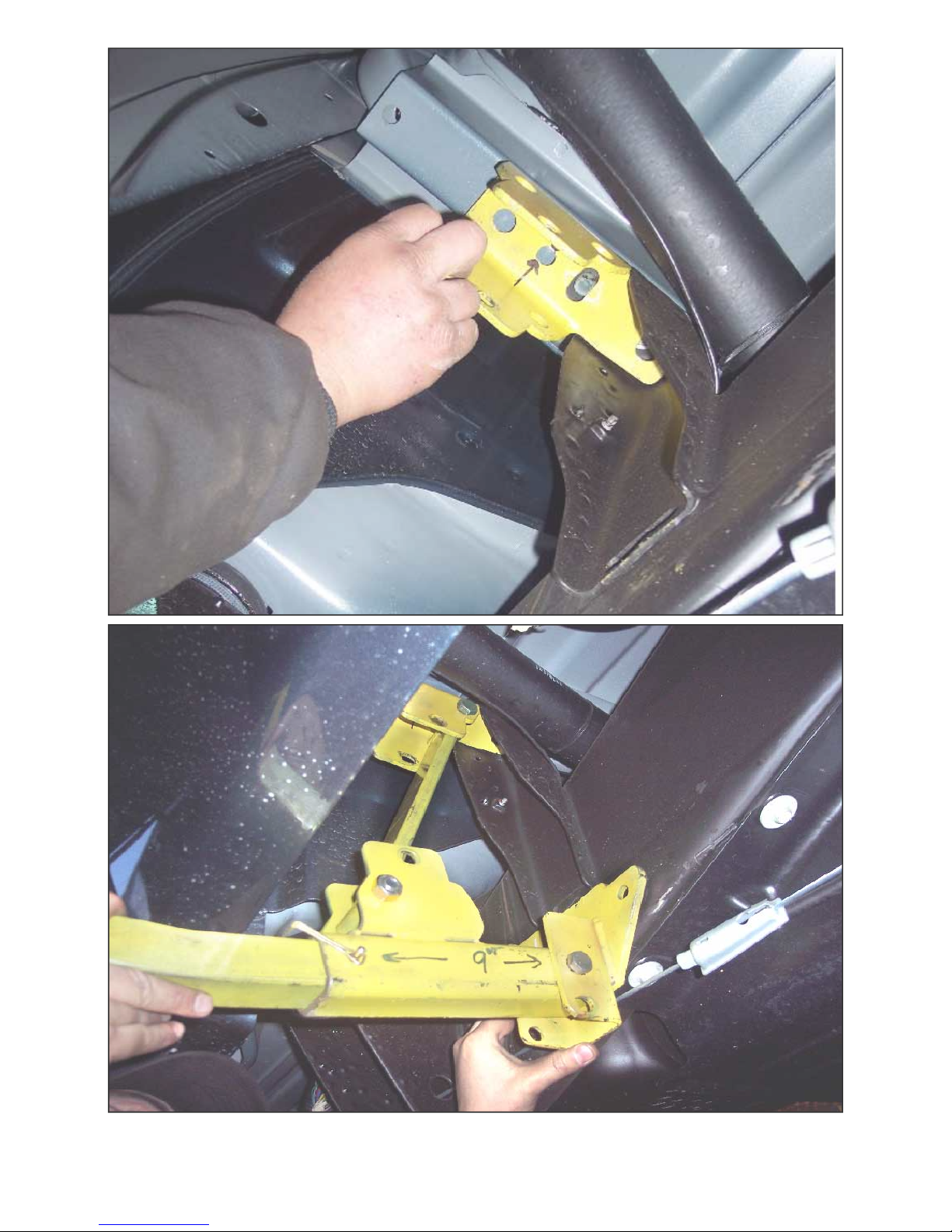
4. Identify upper channel. Looking up at the bottom of the truck box, remove the factory bolt that attaches
the truck box to the frame tower. Install the upper support channel and reinstall the factory bolt. It is nor-
mal to have a gap between the tie down upper support channel and the truck box channel. This gap
will be eliminated when the fasteners are torqued. 07 to current New Body Style trucks skip next
step. Do not drill out the 7/16” hole as you will not use the 3/8” bolt. Now drill out the remaining 7/16
” hole and sh the 1 1/4” x 3/8” hex bolt and at washer in through the end of the box channel with the
supplied bolt sher. Install at washer, lock washer, and nut. Tighten to 35ft lbs. Make sure to keep upper
support channel parallel with the box channel (refer to photos on page 4).
5. Find one bent insert and 1/4” pin and put the bent insert into the tie down receiver using the rst hole in
the insert. Install 1/4” pin.
6. Locate upper support strap and two 1/2” x 3” hex bolts and two locking nuts. Choose the appropriate
holes in the upper and lower channel to give at least 1” clearance between the insert and the lip of the box
or after market accessory. Tighten to 60 ft lbs. See page 6 for correct strap angle information. IMPOR-
TANT! Tighten all fasteners until there is no slack or play between any component.
7. Double-check that all bolts are tight and that there is 1” of clearance between the insert and truckbed lip.
*NOTE: The included tie down inserts come with 2 predrilled pin hole locations. When hooking up
your camper, either hole may be used providing there is a MINIMUM of 2” clearance between the
chain/turnbuckle attaching assembly and the truck bed wall.
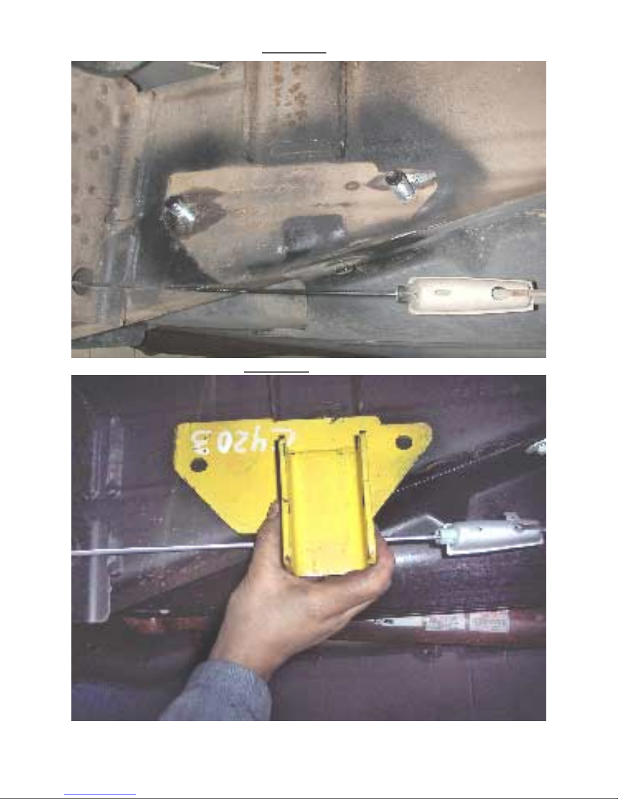
PICTURE OF 2001 CHEVY HEAVY DUTY DRIVER SIDE LONG BED SHOWN
PICTURE OF 01 CHEVY HEAVYDUTY DRIVER SIDE LONG BED SHOWN
ILLUSTRATED DIAGRAMS
ILLUSTRATED DIAGRAMS
 Loading...