

Torklift C2213, C2220 Installation Instructions Manual

1
IMPORTANT OWNER-OPERATOR INSTALLATION INSTRUCTIONS
C2213 / C2220
REVISED vers7 BY: JL 8/5/2015
TECH SUPPORT (800) 246-8132
AFTER INSTALL, PLEASE GIVE
THIS BOOKLET TO YOUR CUSTOMER

2
Warnings
Truck Bed and Camper Protection
Torklift does not recommend installing your camper on top of a plastic bed liner (or other
compressible material such as foam). These materials can act as a spring, causing increased
vertical truck camper movement independent of the vehicle. Plastic bed liners can slide on the
truck bed surface, and the truck camper can slide on top of the bed liner. Using a plastic bed
liner or similar compressible material will void your warranty and may additionally cause truck
bed and/or camper damage.
Minor movement or settling can occur in some incidental harsh driving conditions (on or offroad). A rubber bed mat is recommended to protect the truck bed and camper, but is not a
requirement to maintain the Torklift legendary lifetime warranty.
Suspension
To significantly reduce body roll, sag and sway Torklift strongly recommends the StableLoad.
Torklift International StableLoads improve safety, handling, and to help level your truck. More
information can be found at (www.Torklift.com/stableload).
If your truck is additionally equipped with suspension air bags Torklift cautions against over
pressurization as this may lead to unsafe vehicle handling characteristics. We have found that
airbags used in conjunction with StableLoads have allowed operators to lower air bag pressure
by 50% or more. Only pressurize suspension air bags enough to level the truck.

3
C2213/C2220 PARTS INVENTORY
2- 1-1/2” X 3/16” X 17-7/8”(45cm) BENT INSERT 6- 1/2” GR5 FLAT WASHER
1- 1/2” BOLT FISHER 2- 1/4” X 1” X 2” PLATE WASHER
2- TIE DOWN FRAME PLATE 2- 1/2” GR5 STAR WASHER
2- SPRING PERCH PLATE 2- 1/2” -13 X 1-1/2” GR5 HEX BOLT
6- 1/2” -13 GR5 HEX NUT 2- 1/2” -13 X 2” GR5 HEX BOLT
6- 1/2” GR5 LOCK WASHER 2- 1/2” -13 X 1-1/2” SQUARE BOLT
2- 1/4'” 2-5/8” INSERT SNAPPER PINPIN
INSTALLATION INSTRUCTIONS:
Locate and inventory all parts to become familiar with all brackets. Read
and understand all instructions. Make sure the vehicle is in park, on a
level surface and wheels are chocked before starting the installation.
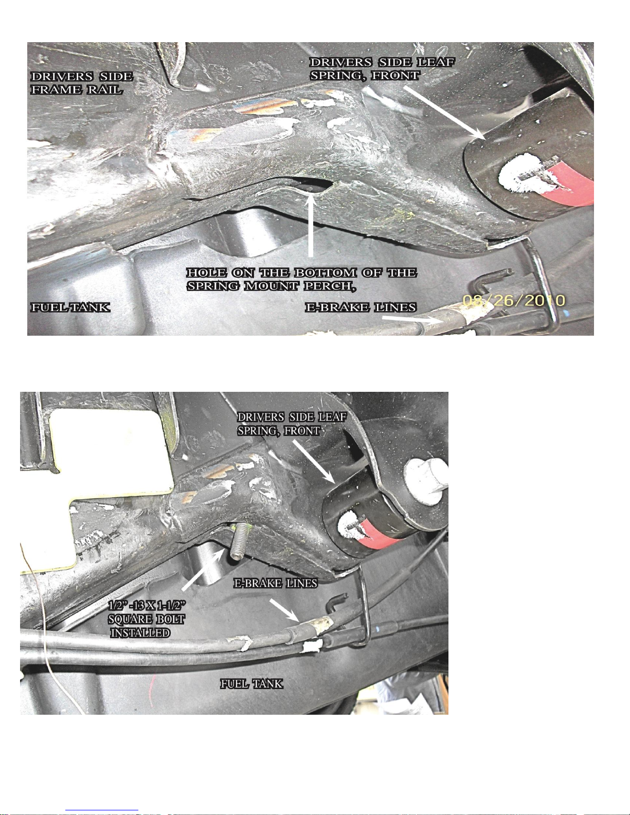
STEP 1
Locate the driver’s side rear axle front spring perch. Insert the 1/2” bolt
fisher coiled end through the small hole on the underside of the spring
perch and out the side. Place one 1/2” -13 x 1-1/2” square bolt onto the
bolt fisher and string it through.
on Page 11
)
See photo 1.1 & 1.2 (
Bolt fishing guide
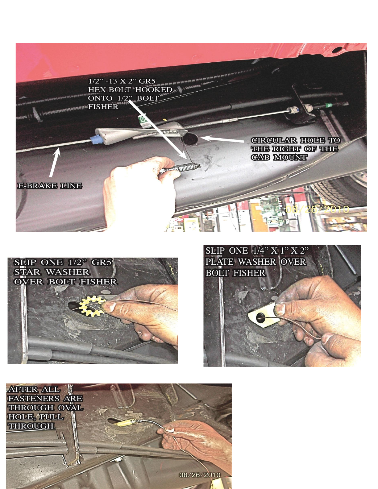
STEP 2
Locate the driver’s side cab and spring mount. Locate the oval hole
between the two mounts and the circular hole just to the front of the cab
mount. Insert the 1/2” bolt fisher’s coiled end first through the oval hole
and out the circular hole. Connect the 1/2” -13 x 2” GR5 hex bolt to the
bolt fisher and string it back through. Once through insert one 1/2” GR5
star washer, and one 1/4” x 1” x 2” plate washer through the open end
of the bolt fisher and place individually through the oval hole and pull
back through.
SEE PHOTO 2.1 & 2.2
4
PHOTO 1.1
PHOTO 1.2
5
PHOTO 2.1
PHOTO 2.2
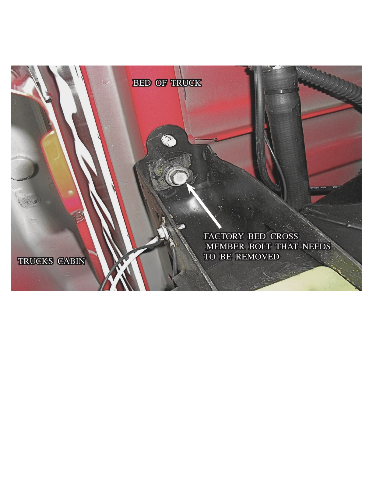
STEP 3
6
Locate the driver’s side front bed cross member perch. Remove the factory bolt
from the perch and bed cross member (keep the factory bolt handy).
PHOTO 3.1
PHOTO 3.1
SEE
STEP 4
Locate the driver’s side tie down and insert the bolt fisher end
through the left hole in the tie down. Place the tie down against
the frame and placing the upper support strap on the tie down up
into the bed cross member perch. Replace the factory bed cross
member bolt and hand tighten. Remove the bolt fisher from the
1/2” -13 x 2” GR5 hex bolt and install one 1/2” GR5 flat washer,
one 1/2” GR5 lock washer and one 1/2” -13 GR5 hex nut.
PHOTO 4.1 & 4.2
SEE
 Loading...