

Torit HPW, HPT, HPH Installation And Operation Manual

Torit® Installation
and Operation Manual
Torit Dust Collector
Models HPW, HPT, and HPH
Includes Installation, Operation, and Service Instructions
HPW
HPT
HPH
IMPORTANT
This manual contains specific precautionary statements relative to worker
safety in appropriate sections. Read this manual thoroughly and comply as
directed. It is impossible to list all of the potential hazards of dust control
equipment or systems. It is imperative that use of the equipment be discussed
with a Torit representative. Personnel involved with the equipment or systems
should be instructed to conduct themselves in a safe manner.
Donaldson Company, Inc. © 1995
IOM-29349-00
Revision 5
1

NOTE
CAUTION
Statements indicate precautions necessary
to avoid potential equipment failure.
CAUTION
APPLICATION OF DUST CONTROL EQUIPMENT:
• Special care must be exercised in the use of
dust collection equipment when combustible
material, such as buffing lint, paper, wood
dust, aluminum, or magnesium dust are
present. These materials may present a fire
or explosion hazard. A prudent user of Torit
equipment should consult and must comply
with all National and Local Fire Codes and/
or other appropriate codes when
determining the location and operation of
dust collection equipment.
• Under no conditions should anyone,
including the machine operator, allow
burning objects or lit cigarettes to enter the
hood or ducting of any dust control system.
• Avoid mixing combustible materials with
dust generated from grinding of ferrous
metals due to the potential fire hazard
caused by sparks being pulled into the dust
collection equipment.
• When collection equipment is used to collect
flammable or explosive dusts, as a minimum,
the dust collection equipment should be
Statements indicate potential safety hazards.
located outside the building. Also, an
installer of fire extinguishing equipment,
familiar with the type of fire hazard and
local fire codes, should be consulted for
recommendations and installation of the
proper fire extinguishing equipment. Torit
equipment does NOT contain fire
extinguishing equipment.
• Explosion relief vents are required on some
applications. Consult with an insurance
underwriter or a NFPA Manual to
determine proper vent sizing requirements.
Vents installed on dust collection
equipment must relieve to the outside of the
building to minimize chances of a
secondary explosion. Consult the proper
authority to determine proper method of
venting the dust collection equipment. Torit
equipment does NOT contain explosion
relief vents, except on special order.
• To insure optimum collector performance,
always use Torit-Built
filters.
®
replacement
Portions of your Torit baghouse, including the clean and dirty chambers of the baghouse, may be considered
"OSHA Permit Required Confined Spaces." OSHA Regulations, found in the Code of Federal Regulations, 29
CFR Section 1910.146 control the entry of "confined spaces." Please refer to this regulation to determine if your
use of the baghouse requires a permit program.
Methods of determining "acceptable entry conditions" vary depending upon the application and the type of dust
collected. In some cases, a visual inspection of airborne dust in the baghouse may be sufficient. In other cases,
chemical tests may be necessary to insure safe entry and occupancy.
Torit recommends that employers follow safe work practices during installation and use of all dust collection
equipment. This includes following applicable OSHA regulations and any other applicable local, state, or
federal laws. Copies of OSHA Regulations can be obtained from your local OSHA office or:
Superintendent of Documents
US Government Printing Office
Washington D.C. 20402 Phone: (202) 783-3238
As always, if you have any questions about your Torit dust collector, do not hesitate to contact your local sales
representative or the Torit headquarters office.
ATTENTION
Donaldson Company, Inc. © 19952
Table of Contents Figures
Notes and Cautions ...................................... 2
Data Sheet ................................................... 3
1.0 Introduction ................................................. 5
1.1 Operational Explanation .............................. 5
1.1.1 Normal Operation ....................................... 5
1.1.2 Filter Cleaning ............................................. 6
2.0 Installation................................................... 6
2.1 Inspection..................................................... 6
2.2 Ship Loose Items .......................................... 6
2.3 Equipment/Tools Required ........................... 7
2.4 Preinstallation .............................................. 7
2.5 Assembly of Standard Equipment ................. 8
2.5.1 General Safety Precautions........................... 8
2.5.2 Erection (Major Collector Components) ....... 9
2.5.3 Filter Tube Installation ............................... 11
2.6 Assembly of Optional Equipment ............... 13
2.6.1 55-Gallon Drum Cover Pack
With or Without Slide Gate .................. 13
2.6.2 Transition Pack.......................................... 14
2.6.3 Transition and Airlock ............................... 15
2.6.4 Magnehelic®* Gage ................................... 16
2.6.5 Photohelic®* Gage ..................................... 17
2.6.6 Level Indicator ........................................... 19
2.6.7 Platform and Handrails.............................. 19
2.6.8 Ladder/Cage .............................................. 20
2.6.9 Light Pack (HPW Only) ............................. 20
2.6.10 Blower Fan Mounting Instructions .............. 21
2.6.11 Damper Pack ............................................. 23
2.7 Electrical Installation ................................. 23
2.7.1 Electrical Operation................................... 24
2.7.2 Solid-State Control Timer Specifications .... 24
2.8 Installation—Compressed Air Supply ......... 26
3.0 Prestart-Up Check ...................................... 27
4.0 Start-Up ..................................................... 27
5.0 Routine Maintenance ................................. 27
5.1 Operating Checks ...................................... 28
6.0 Service ....................................................... 28
6.1 Dust Removal ............................................ 29
6.2 Compressed Air Components ...................... 29
7.0 Troubleshooting Guide ............................... 30
Parts Ordering Information ........................ 36
Warranty ................................................... 36
Figure 1 - Typical Installation View ..................... 4
Figure 2 - Operational Schematic ......................... 5
Figure 3 - Hopper Joint and Leg Attachment ...... 10
Figure 4 - Leg Bracing ....................................... 10
Figure 5 - Sealing Details ................................... 11
Figure 6 - Filter Tube Installation ....................... 12
Figure 7 - Hose Drum Cover Pack with Gate ...... 13
Figure 8 - Hose Drum Cover Pack without Gate . 14
Figure 9 - Transition Pack, Transition,
Figure 10 - Installation of Magnehelic Gage ......... 16
Figure 11 - Installation of Photohelic Gage ........... 17
Figure 12 - Photohelic Gage Wiring Diagram ...... 18
Figure 13 - Weatherproof NEMA 4 Enclosure ...... 18
Figure 14 - Blower Transition Assembly ............... 22
Figure 15 - Damper Assembly .............................. 23
Figure 16 - Solid-State Control Timer
Figure 17 - Compressed Air Manifold .................. 26
* Photohelic and Magnehelic are registered trademarks
of Dwyer® Instruments, Inc.
Torit is the leading designer and manufacturer
of air filtration systems for the control of
industrial air pollution. Its systems are designed
to help reduce occupational hazards, lengthen
machine life, reduce in-plant maintenance
requirements, and improve product quality.
and Airlock................................... 15
Wiring Diagram ........................... 24
Data SheetData Sheet
Data Sheet
Data SheetData Sheet
Customer Name
Address
Shipping Date Installation Date
Model Number Serial Number
Filter Medium
Accessories
Other
Donaldson Company, Inc. © 1995
3

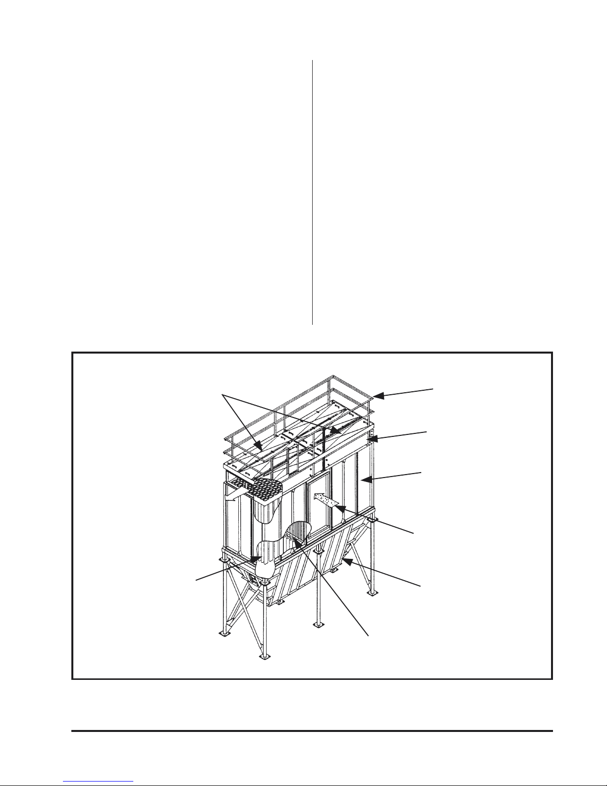
* Asterisk items (*) are not included with Dust Collector.
* Sprinklers.
* Explosion Relief Panels.
* Air Line to Manifold
* Solenoid Electrical Connection
* Power Supply Disconnect Switch
Solid-State Control Timer
* Air Supply Line
* Air Regulator
* Air Filter (Bleed Type)
* Shut-Off Valve
* Automatic Condensate Valve
Hopper
* Blower Fan with Transition
Magnehelic or Photohelic* Gage
* Low Voltage (120 VAC)
Magnetic Starter (Blower Motor)
Figure 1
Typical Installation View (HPH Shown)
Donaldson Company, Inc. © 19954
1.0 Introduction
1.1 Operational Explanation
The Torit HPH, HPT, and HPW are used for
the collection of airborne dust and particulate.
As part of a manufacturing process, the HP
collector series provides highly efficient,
continuous, on-line dust collection.
Standard HP models are available in sizes
ranging from 36 to 320 filter tubes. Other sizes
are available as specials. The standard filter
length is 8 feet. The HPH is a low profile
horizontal filter removal collector; the HPT is a
vertical filter removal collector; and the HPW is
a vertical filter removal collector with a walk-in
top section.
If, after reading this manual, you have further
questions or are in need of technical or field
support, contact your local Torit representative.
1.1.1 Normal Operation
(See Figure 2)
During normal operation, dust-laden air enters
the HP inlet section next to the filter tubes. The
airflow must turn 90° to pass through the filter
tube section. The energy loss from turning and
the reduced velocity in the inlet section causes
the heavier dust particles to drop directly into
the hopper below. A standard inlet baffle helps
evenly distribute the dust-laden air around the
filter tubes. The dust is collected on the outside
surface of each filter tube where it forms a cake
that aids in filtering efficiency. Filtered (clean)
air passes through each filter tube into the clean
air plenum where it is discharged through the
clean air outlet.
Filter Tube Access Doors
Clean Air Outlet
Filter Tubes
Handrail
Clean Air Plenum
Dirty Air Plenum
Dirty Air Inlet
Hopper
Inlet Baffle
Donaldson Company, Inc. © 1995
Figure 2
Operational Schematic (HPT Shown)
5

1.1.2 Filter Cleaning
Filter tubes are cleaned automatically and
sequentially. Only one row of filter tubes is
cleaned per pulse. During the filter tube cleaning
purge, the solid-state timer energizes a solenoid
valve. This action causes the corresponding
diaphragm valve to send a pulse of compressed
air out into the blowpipe. The blowpipe is
equipped with two high pressure nozzles
centered over each oval shaped filter tube. The
high pressure pulse enters the inside of the filter
tube forcing air through the filter. The collected
contaminants are blown away from the outside
surface of the filters. The dust falls into the
hopper where it is discharged into drums, screw
conveyor, or rotary valve.
2.0 Installation
2.1 Inspection
The collector is normally shipped with major
components preassembled when possible.
However, due to space restrictions and/or to
minimize freight costs, some components may be
shipped unassembled and nested. On most
HPW/T models, the clean air plenum, dirty air
plenum, and hopper/support weldment are
unassembled.
A crane is recommended for unloading,
assembly, and installation of the dust collector.
Before unloading major components, such as
housing and hopper, check inside for smaller
items that could be damaged if not removed
first. Unload components in a location that
allows for parts identification and assembly.
The filter tubes should be stored in a dry,
rodent-proof area until ready for installation.
2.2 Ship Loose Items
Items shipped loose with the HP dust collector
may include:
• Hopper
• Legs and Cross Bracing
• 55-Gallon Drum Cover Pack
• Transition Pack
• Magnehelic Gage or Photohelic Gage
• Control Box
• Hardware/Sealant
• Explosion Vent
• Weather Cover
• Platforms
• Ladders
• Ladder Cages
• Air Locks
• Tubesheet
• Filter Tubes
• Filter Cages
• Blowpipes (HPH only)
On most HPH models, the clean air plenum is
assembled to the dirty air plenum and the
hopper and support are unassembled. Also, the
blowpipes are unassembled to facilitate filter
tube installation. In most cases, the filter tubes
and frames are shipped separate (unassembled)
for all models.
A packing list is enclosed with each dust
collector. If there are any questions about
completeness of a shipment or obvious damage
to packaged parts, notify the carrier
immediately. Also, damage to any section of the
shipment should be noted on the carrier's Bill of
Lading.
Donaldson Company, Inc. © 19956

2.3 Equipment/Tools Required
The following is a list of typical tools and
equipment required to install and assemble an
HP dust collector:
• Crane/Lift Truck
• Slings/Spreader Bars/Clevice Pins
• Drift Pins
• Clamps
• Screwdrivers
• Pipe Wrenches
• Socket Wrenches
• End Wrenches
• Large Crescent Wrench
• Drill and Drill Bits
• Pipe Sealant
• Extension Cords
• Trouble Light
2.4 Preinstallation
(See Figure 1)
The HP dust collector is usually mounted on a
reinforced concrete foundation. However, roof
mounting is also possible. When calculating for
foundation or roof mounting, the weight of both
the dust collector, the material being collected,
and all auxiliary equipment must be considered
together with wind, seismic and other live loads.
See the Specification Control Drawing for the
dust collector weight.
CAUTION
• Location must be clear of all
obstructions such as utility lines or roof
overhang (see Specification Control
Drawing).
NOTE
Wearing safety equipment such as helmets
and glasses is recommended for all persons
while working in or around the collector.
CAUTION
Use appropriate lifting equipment and
adopt all the safety precautions needed for
moving and handling the equipment.
• A crane must be used to move the
collector into position.
To avoid delay, install foundation in the proper
location. Pay particular attention to the anchor
bolt location. Anchor bolts must extend at least
1-3/4" above foundation. The collector should
be located with consideration for emptying
hopper storage area, shortest runs of inlet and
outlet ductwork, electrical and compressed air
connections, and convenience of maintenance.
In case of hazardous dust collection, consult
with local authorities for the proper location of
the dust collector.
Donaldson Company, Inc. © 1995
7

2.5 Assembly of Standard Equipment
(See Figure 1)
CAUTION
• A crane is recommended for the
unloading, assembly, and installation
of the dust collector.
• Connect lifting sling to a minimum of 4
lifting lugs. Distribute loads equally.
Use clevices, not hooks, on lifting sling.
Use spreader bars on lifting sling.
2.5.1 General Safety Precautions
1. Be certain that the crane has sufficient
capacity to lift sections, sub-assemblies and
complete units, if that applies. Check
weights and dimensions of dust collector
components on specification drawings
furnished by Torit. Spreader bars are
recommended between lifting cables;
shallow cable angles should be avoided.
2. No person shall operate the crane or other
erection equipment except those qualified by
training and experience.
3. Do not install during gusty or heavy winds.
Remove all crating and strapping from the unit.
Remove all miscellaneous parts (bolts, nuts, etc.)
before lifting unit off of the truck. Check the
parts received against the packing slips. If there
are parts missing, the carrier and your local
Torit Representative should be notified
immediately.
NOTE
Each item to be attached to your collector
is accompanied by a drawing that shows
the attachment process. Refer to both the
drawing and this manual when erecting
your collector.
4. Note location of adjacent structures, power
lines, traffic, unstable ground, and ground
obstacles in the erection area.
5. Never swing loads over personnel.
6. Use conventional hand signals for crane
operators.
7. Always consider electrical lines to be live
(hot).
8. Provide an observer to assist crane operator
for periods of impaired visibility.
9. Refer to applicable OSHA regulations and
local rules in using cranes, forklifts, and
other erection equipment.
10. Make liberal use of drift pins to align holes
in section flanges during assembly.
11. Wear appropriate safety gear including hard
hats and safety glasses.
Donaldson Company, Inc. © 19958
2.5.2 Erection (Major Collector Components)
HPT/W Units Only - (Hopper & Legs)
CAUTION
Do not disconnect crane until the lifted
component is securely fastened in place.
The following general procedure is
recommended for assembly:
NOTE
• If the dust collector is shipped
preassembled, including support legs, it
may be lifted directly from the truck
onto the foundation.
• If the dust collector is shipped
unassembled, see Specification Control
Drawing for correct orientation and
location of components.
1. The HPT/HPW hopper/leg arrangements
come totally assembled.
2. Lift the hopper/leg assembly, using a crane,
into position over the anchor bolts and lower
down onto the anchor bolt pads. Fasten the
legs to the anchor bolts with washers and
nuts (provided by customer). Level the
hopper at the top flange in all directions by
placing solid steel shims under the leg pads.
Tighten the nuts on the anchor bolts. Recheck level and adjust as required. Remove
the crane from the hopper.
3. Apply 1/4" diameter sealant to the top
flange all around toward the inside edge of
the bolt pattern (see Figure 5, Sealing
Details).
• All flanged connections of components
providing air seals, including clean air
plenum, tube section, and hopper, must
be sealed before assembly with sealant
as shown in Figure 5, Sealing Details
unless they are factory assembled.
• Use spreader bars for lifting sections of
collector.
• Use drift pins to align holes during
erection.
• Filter tubes and cages can be installed
before or after collector is erected.
Donaldson Company, Inc. © 1995
9

HPH Units Only - (Hopper & Legs)
(See Figures 3 and 4)
1. HPH units have unassembled leg sets.
Locate and identify all legs, bracing, and
hardware required for leg set. Organize the
legs and bracing for assembly.
2. Lift the hopper using a crane and position
over the four legs. Stand each leg up on its
pad, one at a time, and position the hopper
gusset holes to line up with the holes in the
leg. Use a drift pin to assist in hole
alignment. Fasten each leg using the proper
bolts, washers, and nuts provided. Do not
tighten any hardware at this time. Do not
disconnect the crane.
3. Position the inside angle of the cross bracing
and bolt in place using the proper bolts,
washers, and nuts provided. Do not tighten.
Position the outside angle of the cross
bracing and bolt in position. Where the two
angles cross, bolt through each hole with a
bolt, washers, and nut. Repeat this sequence
on the opposite side of the hopper. Do not
tighten hardware.
4. Lift the hopper leg assembly into position
over the anchor bolts and lower down onto
the anchor bolt pads. Fasten the legs to the
anchor bolts with washers and nuts
(provided by customer). Level the hopper at
the top flange in all directions by placing
solid steel shims under the leg pads. Tighten
all hardware on the gussets, cross bracing,
and anchor bolts. Re-check level and adjust
as required. Remove the crane from the
hopper.
5. Apply 1/4" diameter sealant to the top
flange all around toward the inside edge of
the bolt pattern (see Figure 5, Sealing
Details).
Dirty Air Plenum
Hopper
Leg
Figure 3
Hopper Joint and Leg Attachment
(HPH Only)
Cross Bracing
Figure 4
Leg Bracing
(HPH Only)
Donaldson Company, Inc. © 199510

Dirty Air Plenum
Clean Air Plenum
Dirty Air Plenum to
Hopper Joint
1/4" Dia.
Sealant
Hopper
1/4" Dia. Sealant
Tubesheet
Sealant
Dirty Air Plenum
Clean Air Plenum to
Dirty Air Plenum Joint
Figure 5
Sealing Details
Apply Sealant Between
Flanges, on Inside of Bolt
Pattern
Sealing Detail
2.5.3 Filter Tube Installation
(See Figure 6)
Several filter medias are available to meet the
filtration needs for many different types of dust.
Contact your local Torit representative for
assistance in choosing the correct media for
your dust collection requirements.
The cages will arrive on site packaged in crates.
The filters will arrive on site packaged in boxes.
Choose a clean area for pre-assembly of the
filters onto the cages.
Installing the filters before the filter section is
raised will be easier and save time. Install the
filter tubes as shown in Figure 6, Filter Tube
Installation. Slip the filter tube over the filter
tube frame until it touches the top flange of the
Donaldson Company, Inc. © 1995
frame. Slide this filter assembly through the
tubesheet. Align the two bolts with the threaded
inserts in the tubesheet. Secure each filter tube
and frame assembly with the Boltsafe™
hardware provided.
NOTE
• Use a speed wrench to tighten the
screws. Do not use a power driver or
impact nut driver. These may strip
threads or shear screws.
• Only tighten screws until the top flange
rests on the tubesheet, about 8-10 ft. lbs
torque.
11
 Loading...