

Torit Downflo SDF-2, Downflo SDF-4, Downflo SDF-6 Installation And Operation Manual
Torit® Installation
and Operation Manual
FOR TORIT FILTER CARTRIDGE SYSTEM DUST COLLECTORS
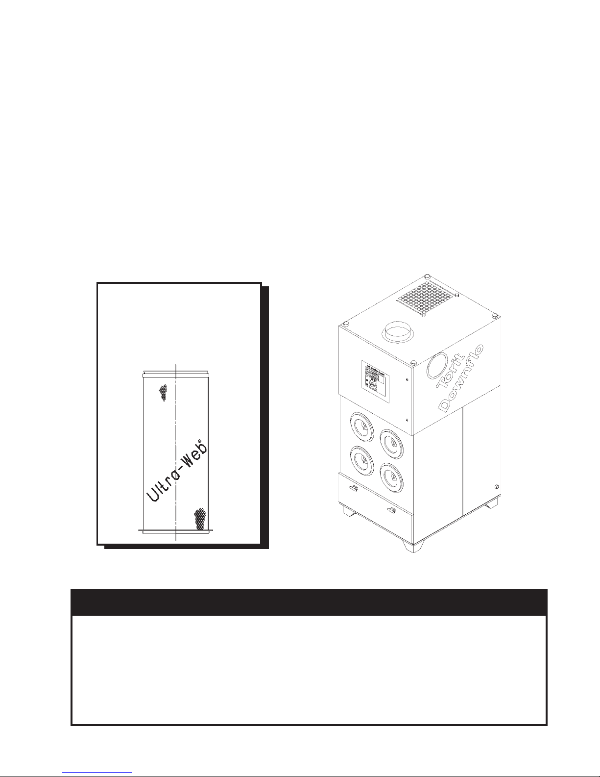
Torit Downflo® Models SDF–2, SDF–4, SDF–6
Includes Installation, Operation, and Service Instructions
WITH QUICK-CHANGE
ULTRA-WEB® II
FIBRA-WEB
ULTRA-TEK
FILTER ELEMENTS
®
®
This manual contains specific precautionary statements relative to worker
safety in appropriate sections. Read this manual thoroughly and comply as
directed. It is impossible to list all of the potential hazards of dust control
equipment. It is imperative that use of the equipment be discussed with a Torit
representative. Personnel involved with the equipment or systems should be
instructed to conduct themselves in a safe manner.
Donaldson Company, Inc. © 1995
IMPORTANT
IOM-46740-00
Revision 5
1
NOTE
CAUTION
Statements indicate precautions necessary
to avoid potential equipment failure.
CAUTION
Application of Dust Control Equipment:
• Special care must be exercised in the use of
dust collection equipment when combustible
equipment, such as buffing lint paper, wood
dust, aluminum, and magnesium are present.
These materials may present a fire or
explosion hazard. A prudent user of Torit
equipment should consult and must comply
with all National and Local Fire Codes and/
or other appropriate codes when determining
the location and operation of dust collection
equipment.
• Under no conditions should anyone, including
the machine operator, be allowed to put
burning objects or lit cigarettes into the hood
or ducting of any dust control system.
• Avoid mixing combustible materials with
dust generated from grinding of ferrous
metals due to the potential fire hazard caused
by sparks being pulled into the dust collection
equipment.
Statements indicate potential safety hazards.
collection equipment should be located
outside the building. Also, an installer of
fire extinguishing equipment, familiar with
this type of fire hazard and local fire codes,
should be consulted for recommendations
and installation of the proper fire
extinguishing equipment. Torit
does NOT contain fire extinguishing
equipment.
• Explosion relief vents are required on some
applications. Consult with an insurance
underwriter or a NFPA Manual to
determine proper vent sizing requirements.
Vents installed on dust collection equipment
within a building must relieve to the outside
of the building to minimize chances of a
secondary explosion. Consult the proper
authority to determine proper method of
venting the dust collection equipment. Torit
equipment does NOT contain explosion
relief vents, except on special order.
equipment
• When collection equipment is used to collect
flammable or explosive dusts, the dust
2
• To insure optimum collector performance,
always use Torit-Built® replacement
filters.
TORIT PRODUCTS is the leading designer and
manufacturer of dust collector systems for the
control of industrial air pollution. Its systems are
designed to help reduce occupational hazards,
lengthen machine life, reduce in-plant maintenance
requirements, and improve product quality.
Donaldson Company, Inc. © 1995

Table of Contents
Notes and Cautions ............................. 2
Data Sheet ........................................... 3
Figures ................................................. 4
1.0 Introduction ......................................... 6
1.1 Operational Explanation ..................... 6
1.1.1 Normal Operation ............................... 6
1.1.2 Filter Cleaning ..................................... 7
2.0 Installation ........................................... 7
2.1 Inspection............................................. 7
2.2 Ship Loose Items .................................. 7
2.3 Equipment/Tools Required................... 7
2.4 Assembly of Standard Equipment ........ 7
2.5 Assembly of Optional Equipment ........ 8
2.5.1 Compressed Air Inlet Adapter ............. 8
2.5.2 Leg Levelers ......................................... 8
2.5.3 Inlet Collar ........................................... 8
2.5.4 Adapter to Round Outlet ..................... 8
2.5.5 Adapter Auto-Lok™/Ultra-Lok™ ....... 8
2.5.6 Adapter HEPA/Activated Carbon ...... 12
2.5.7 Leg Pack SDF ..................................... 12
2.5.8 55-Gallon Drum Pack ......................... 14
2.5.9 5-Gallon Pail Pack .............................. 14
2.5.10 Bin Vent Base Pack ............................. 14
2.5.11 Flex-Trunk™ Assembly
7-Foot/10-Foot SDF ............................ 16
2.5.12 Weather Hood Pack ........................... 16
2.5.13 Explosion Vent Pack ........................... 16
2.5.14 Explosion Vent Cabinet ...................... 20
2.6 Electrical Installation ............. 20-23,29-30
2.6.1 Electrical Operation ............................ 30
2.6.2 Checker
Control Panel Specifications ............... 30
2.6.3 Solid State Control Timer
Specifications ................................... 30-31
2.6.4 Magnehelic
2.6.5 Torit ∆P Control .............................. 33-35
2.6.6 Photohelic
2.7 Compressed Air Supply Installation.... 38
2.7.1 Air Manifold Assembly ....................... 39
2.7.2 Blower Compartment ......................... 39
2.7.3 Dust Storage Compartment ................ 39
4.0 Start-up ............................................... 39
5.0 Operating Adjustment ........................ 40
5.1 Checker Board .................................... 40
5.2 Solid State Control Timer ................... 40
5.3 ∆P Control Calibration ....................... 41
5.4 Outlet Damper Adjustment................. 41
5.5 Operating Checks ............................... 41
6.0 Service ................................................ 42
6.1 Filter Element Removal ...................... 42
6.2 Filter Element Installation ................... 42
6.3 Bag-Out Filter Element Removal .....42-43
6.4 Dust Removal Dust Container ........ 43-44
6.4.1 Dust Removal—Hopper Model .......... 44
6.5 Compressed Air Components ............. 45
6.6 Electrical Service ................................ 45
7.0 Troubleshooting Guide .................... 46-52
Parts Ordering Information ................ 54
Warranty ............................................ 54
™
Board, Diagnostics and
®
* Gage ............................ 31
®
* Gage .............................. 37
Data Sheet
* Magnehelic and Photohelic are registered trademarks
of Dwyer® Instruments, Inc..
Customer Name
Address
Shipping Date Installation Date
Model Number Serial Number
Filter Medium
Accessories
Other
Donaldson Company, Inc. © 1995
3

Figures
Figure 1 – SDF-4 Phantom View .............. 5
Figure 2 – Operational Schematic ............ 6
Figure 3 – Compressed Air Inlet Adapter 8
Figure 4 – Leg Levelers ............................ 8
Figure 5 – Inlet Collar .............................. 9
Figure 6 – Adapter Pack to
Round Outlet .......................... 9
Figure 7 – Adapter Pack
Auto-Lok/Ultra Lok ................10
Figure 8 – Adapter Pack HEPA/
Activated Carbon.................... 11
Figure 9 – Leg Pack SDF .......................... 12
Figure 10 – 55-Gallon Drum Pack &
5-Gallon Pail Pack................... 13
Figure 11 – Bin Vent Base Pack ................. 14
Figure 12 – Flex-Trunk Assembly
7-Foot/10-Foot SDF................. 15
Figure 13 – Weatherhood Pack .................. 17
Figure 14 – Explosion Vent Pack ............... 18
Figure 15 – SDF-4 with Explosion Vents—
Phantom View ......................... 19
Figure 16 – Prewired with Checker Board
on Unit .................................... 21
Figure 17 – Unwired with Checker Board
on Unit .................................... 21
Figure 18 – Prewired with Checker Board
in Remote Enclosure ...............22
Figure 19 – Unwired with Checker Board
in Remote Enclosure ...............23
Figure 20 – Wiring Diagram 575V 60Hz
3PH 3, 5, 7-1/2, 10 hp ............ 24
Figure 21 – Wiring Diagram 380V 50Hz
3PH 3, 5 hp .............................24
Figure 22 – Wiring Diagram 380V 50Hz
3PH 7-1/2 hp ........................... 25
Figure 23 – Wiring Diagram 230V 60Hz
3PH 3, 5, 7-1/2, 10 hp ............ 25
Figure 24 – Wiring Diagram 200V 50/60Hz
3PH 3, 5 hp .............................26
Figure 25 – Wiring Diagram 200V
50/60Hz 3PH 7-1/2, 10 hp ...... 26
Figure 26 – Wiring Diagram 460V 60Hz
3PH 3, 5, 7-1/2, 10 hp ............. 27
Figure 27 – Wiring Diagram 208 V
60Hz 3PH 3, 5, 7-1/2, 10 hp ... 27
Figure 28 – Remote Checker Board
Assembly ................................. 28
Figure 29 – SDF Solid-State Timer Wiring
Diagram .................................. 29
Figure 30 – Magnehelic Gage .................... 32
Figure 31 – Remote-Mounted Magnehelic
Gage .......................................32
Figure 32 – ∆P Control Display ................. 33
Figure 33 – Printed Circuit Board ..............35
Figure 34 – Photohelic Gage ......................36
Figure 35 – Remote-Mounted Photohelic
Gage .......................................36
Figure 36 – Photohelic Gage
Wiring Diagram ...................... 37
Figure 37 – Air Manifold Assembly ........... 38
Figure 38 – Bag-Out Assembly .................. 43
Figure 39 – Bag-Out Filter Removal .......... 43
Figure 40 – Dust Container Support
System..................................... 44
Figure 41 – Typical Electrical
Component Assembly ............. 45
4
Donaldson Company, Inc. © 1995
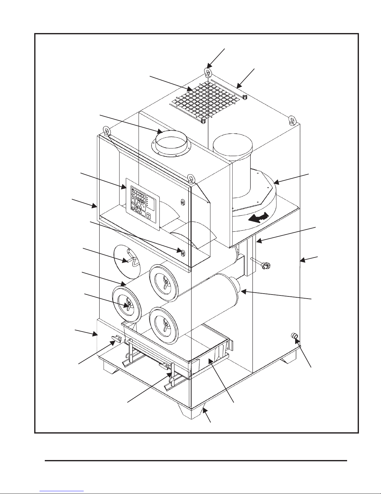
Sprinkler Taps (not shown) (not supplied standard with the SDF)
Lifting Eyes
Inlet Collar
Checker™ Board
Diagnostic and
Control Panel
Hinged Access
to Electrical
Compartment
Tool Operated
Fastener
Filter Yoke
Filter Element
Outlet with Damper
Screwed-on Rear
Access Panel to
Blower Compartment
Blower Pack
Air Manifold
Assembly
Screwed-on
Rear Access
Panel to Clean
Air Manifold
Filter Wing
Nut
Hinged Access
Door to Dust
Container
T–Handle
Quick Latch
Lift Assembly Dust
Container
Donaldson Company, Inc. © 1995
Venturi
Compressed Air Inlet—
1/2 National Pipe
Threads or British Pipe
Threads
Dust Container
Legs or Casters
Figure 1
SDF–4 Phantom View
5
1.0 Introduction
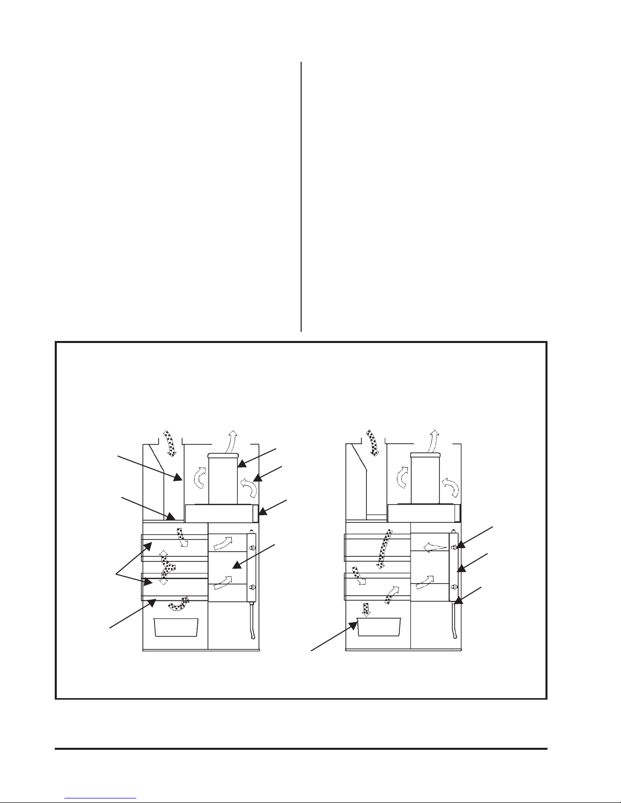
1.1 Operational Explanation
(See Figure 2 Operational Schematic)
The Torit® Downflo® model SDF dust collector
is used for the collection of airborne dust and
particulate. The model SDF collector provides
highly efficient, continuous, on-line dust
collection.
®
The Torit-Built
filter elements are the heart of
the model SDF dust collector. These filter
elements help ensure that clean air is returned to
the plant environment.
Technical and field support are always available
from your local Torit representative and
distributors.
Normal Operation
1.1.1 Normal Operation
During normal operation, contaminated air
enters through the top inlet area and passes
down and through the filter elements. Dust is
collected on the outside surface of the filter
elements. The clean, filtered air flows through
the center of the filter elements and into the
clean air plenum, where it exits through the
clean air outlet.
Filter Element Purge
Dirty Air Plenum
Deflector
Filter
Elements
Filter Section
Dirty Air Inlet
Clean Air Outlet
Blower Pack
Silencer
Section
Fan Outlet
Clean Air
Plenum
Dirty Air Inlet
Diaphragm
Cleaning Air
Valve
Compressed
Air Manifold
Compressed
Air Inlet Fitting
(Purge Air)
6
Figure 2
Operational Schematic
Donaldson Company, Inc. © 1995

1.1.2 Filter Cleaning
2.3 Equipment/Tools Required
Filter elements are cleaned automatically and
sequentially. The result is that only one filter
cartridge will be off-line for cleaning at any
given time.
During the filter element cleaning purge, a
solenoid valve is energized, causing the
corresponding diaphragm valve to send a pulse
of compressed air through the filter element
(from the inside outward), removing the
collected dust from the outside surfaces of the
filter element. The dust falls into the dust storage
container.
2.0 Installation
2.1 Inspection
The Downflo SDF is normally shipped by
common carrier and should be checked for
damage that may have occurred en route. Any
damage should be noted and the carrier notified
immediately.
The following is a list of typical tools and
equipment required to install and assemble a
Downflo SDF unit.
• Crane/Lift Truck
• Pipe Wrenches
• Socket Wrenches
• Pipe Sealant
2.4 Assembly of Standard Equipment
NOTE
A crane or forklift truck is recommended
for the unloading of the dust collector.
CAUTION
• Connect lifting slings to the four lift
lugs on top of the dust collector when
using a crane to unload the unit.
2.2 Ship Loose Items
Items shipped loose with the dust collector may
include:
• Bag-out Assembly
• Inlet Collar
• Compressed Air Inlet Adapter
• (4) Leveling Mount Foot Pads
• (4) Metric Hex Bolts
• Hopper
• Legs and Crossbracing
• Outlet Adapters
• Auto-Lok/Ultra-Lok/HEPA/Carbon Filter
• Remote Checker Board/
Magnehelic Gage/Photohelic Gage
• Slide Gate/55-Gallon Drum Cover Pack
• 5-Gallon Pail Pack
• Flex-Trunk Assembly
• Weather Hood
• Explosion Vents
• Insert the fork under the dust
collector between the casters or legs
when using a forklift truck to unload
the unit.
Remove all crating and strapping from the unit.
Remove all miscellaneous parts (bolts, nuts, etc.)
before lifting the unit off of the truck. Check the
parts received against the packing list. If there
are parts missing, the carrier and your local
Torit representative should be notified
immediately.
NOTE
If the lift lugs are removed, they must be
replaced with the four (4) metric hex
bolts (provided) before the dust collector
is operated.
Most cabinets are shipped completely assembled
with the filter cartridges installed.
Donaldson Company, Inc. © 1995
7

2.5 Assembly of Optional Equipment
2.5.4 Adapter to Round Outlet (See Figure 6
Adapter Pack to Round Outlet)
2.5.1 Compressed Air Inlet Adapter
(See Figure 3 Compressed Air Inlet
Adapter)
The compressed air inlet adapter is used for
converting the compressed air inlet from
National Pipe Threads to British Pipe Threads.
Install the compressed air inlet adapter as shown
in Figure 3 Compressed Air Inlet Adapter. Use
thread-sealing tape or pipe sealant on the
threaded adapter before screwing it into the
compressed air inlet.
2.5.2 Leg Levelers (See Figure 4 Leg Levelers)
The leveling mount foot pads screw into the
bottom of the collector legs as illustrated in
Figure 4 Leg Levelers.
2.5.3 Inlet Collar (See Figure 5 Inlet Collar)
Place 1/4" diameter sealant between the cabinet
side or top and the inlet collar. Attach the collar
using the eight (8) #6-32 thread cutting screws
provided.
Place the 3/16" x 1/2" rubber seal between the
cabinet top and the outlet adapter. Attach the
outlet adapter to the cabinet using the clamp
hook, wing nut, and washer as shown. The
sliding damper will still operate with this
adapter.
2.5.5 Adapter Auto-Lok / Ultra-Lok
(See Figure 7 Adapter Pack
Auto-Lok / Ultra-Lok )
Remove the lift lug on the cabinet top and
replace it with the set screw. Place the 3/16" x
1-1/4" gasket between the cabinet top and the
adapter. Attach the adapter to the cabinet top
using the clamp hooks, wing nuts, and washers
as shown. Place the 3/8" x 1-1/4" gasket
between the adapter and the Auto-Lok or UltraLok filter as shown. Use the 10-24 x 7/16 screws
to attach the filter to the adapter. The sliding
damper will not operate with these adapters.
Compressed Air Inlet
Collector
Leg or Caster
Figure 3
Compressed Air Inlet Adapter
8
Sealant
Compressed Air
Inlet Adapter
Collector
Leg
Leveling
Mount Foot
Pad
Figure 4
Leg Levelers
Donaldson Company, Inc. © 1995

#6-32 Screws
Inlet Collar
Cabinet Top or Side
1/4" Diameter Sealant
Figure 5
Inlet Collar
Wing Nut
3/8 Flat Washer
Rubber Seal
Cabinet Top
(Ref)
Adapter Pack to Round Outlet
Donaldson Company, Inc. © 1995
Outlet Adapter
Clamp Hook
Figure 6
9
3/8 x 1-1/4 Gasket
Adapter
Auto-Lok /
Ultra-Lok
Assembly
10-24 x 7/16 Screw
3/16 x 1-1/4 Gasket
Cabinet Top (Ref)
10
Wing Nut
3/8 Flat Washer
Set Screw
Clamp Hook
Figure 7
Adapter Pack Auto-Lok / Ultra-Lok
Donaldson Company, Inc. © 1995
Filter Retainer Bar
Adapter
1/4-20 x 3/4 Bolt
1/4 Flat Washer
HEPA /
Carbon Filter
1/4 x 3/4
Gasket
3/16 x 1-1/4 Gasket
Cabinet Top (Ref)
Wing Nut
3/8 Flat Washer
Set Screw
Clamp Hook
Figure 8
Adapter Pack HEPA / Activated Carbon
Donaldson Company, Inc. © 1995
11
2.5.6 Adapter HEPA / Activated Carbon
(See Figure 8 Adapter Pack HEPA /
Activated Carbon)
Remove the lift lug on the cabinet top and
replace it with the set screw. Place the 3/16" x
1-1/4" gasket between the cabinet top and the
adapter. Attach the adapter to the cabinet using
the clamp hooks, wing nuts, and washers as
shown. Place the 1/4" x 3/4" gasket between the
adapter and the HEPA or Activated Carbon
filter as shown. Use the filter retainer bar and
the 1/4" bolts and washers to attach the filter to
the adapter. The sliding damper will not operate
with these adapters.
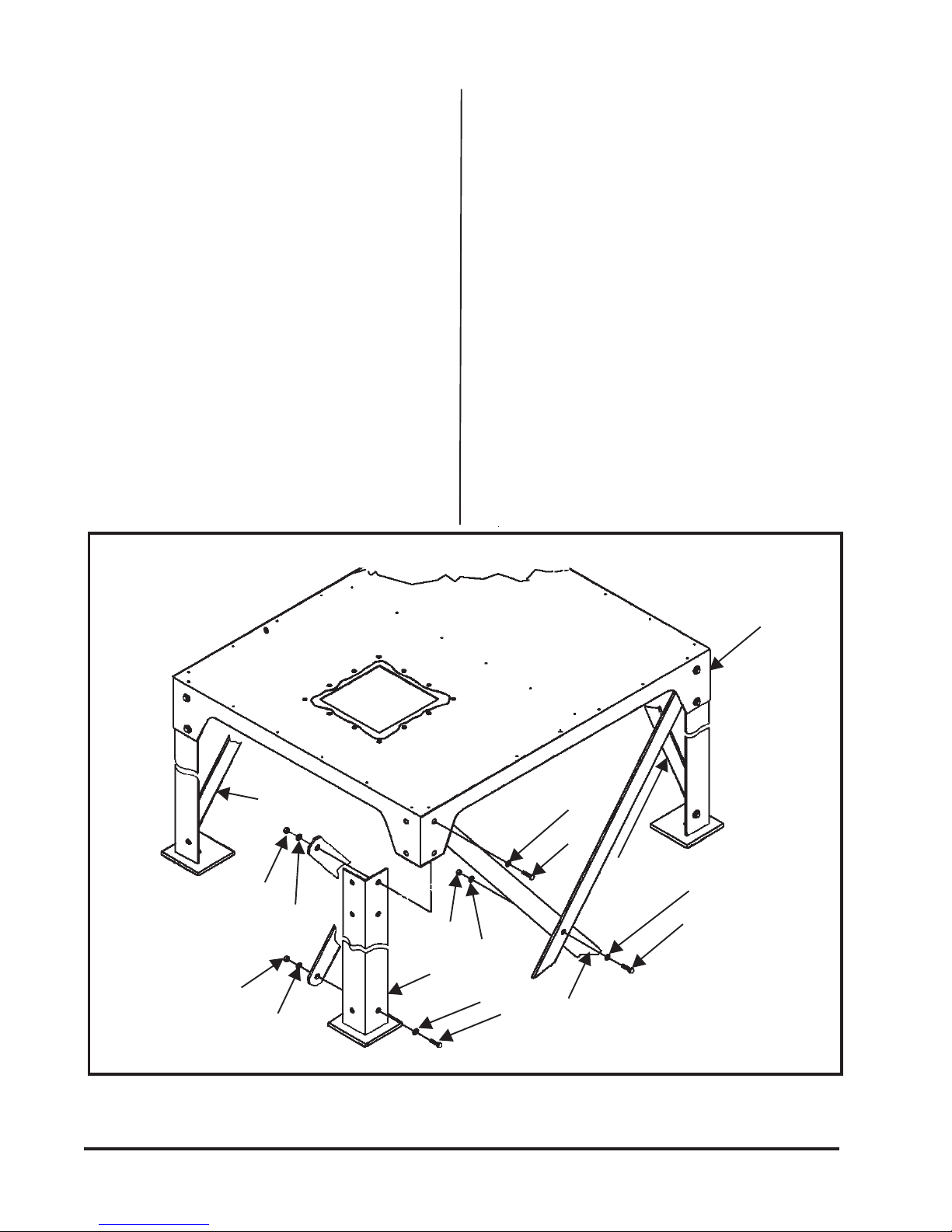
2.5.7 Leg Pack SDF
(See Figure 9 Leg Pack SDF)
The SDF units that are not furnished with a dust
container will have an internal hopper with a
base to attach to legs and crossbracing.
Assemble the legs and crossbracing to the SDF
base as shown in Figure 9 Leg Pack SDF. The
55-gallon drum pack leg crossbraces should be
installed on the three sides only, in order to
allow access to the drum. The 5-gallon pail pack
does not require crossbracing.
Nut
Washer
Crossbrace
Nut
Washer
Nut
Leg
Washer
Washer
Bolt
SDF Base
Washer
Bolt
Crossbrace
Washer
Bolt
Crossbracing
12
Figure 9
Leg Pack SDF
Donaldson Company, Inc. © 1995

Attach to SDF Base as Shown
SDF Base
1/4" Dia. Seal
Bolts, Washers,
& Nuts
55-Gallon Drum Pack
With or Without Gate
With or Without Latches
55-Gallon Drum Pack and 5-Gallon Pail Pack
Donaldson Company, Inc. © 1995
5-Gallon Pail Pack
With or Without Gate
Figure 10
13
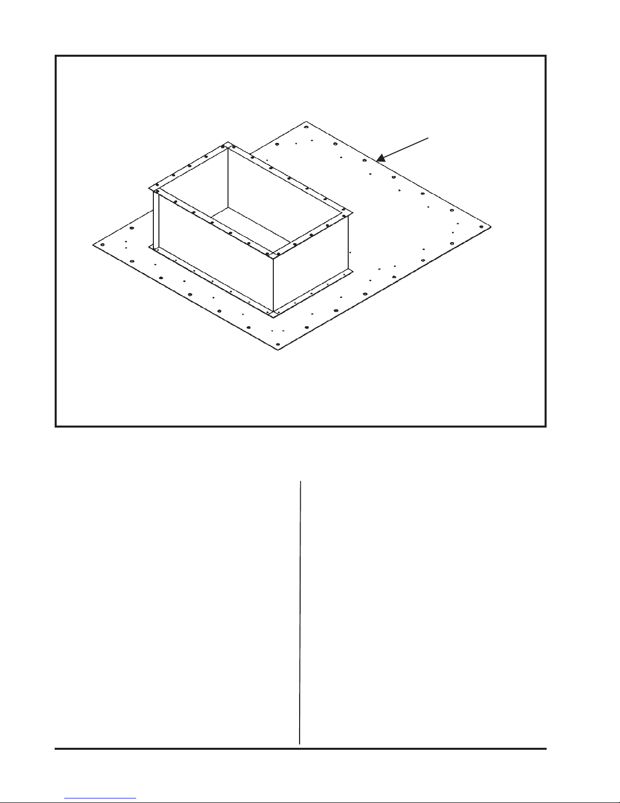
Bin Vent Base
1/2" Diameter Holes (28)
Figure 11
Bin Vent Base Pack
2.5.8 55-Gallon Drum Pack
(See Figure 10 55-Gallon Drum Pack
and 5-Gallon Pail Pack)
The 55-gallon drum cover and the 55-gallon
drum cover with gate can be attached to the
base as shown in Figure 10 55-Gallon Drum
Pack and 5-Gallon Pail Pack. Use the existing
bolts, washers, and nuts that are on the base.
Access to the bolts is through the hinged door.
Be sure to use sealant to seal between the drum
cover and the base.
2.5.9 5-Gallon Pail Pack
(See Figure 10 55-Gallon Drum Pack
and 5-Gallon Pail Pack)
Attach the 5-gallon pail cover and the 5-gallon
pail cover with gate as shown in Figure 10
55-Gallon Drum Pack and 5-Gallon Pail Pack.
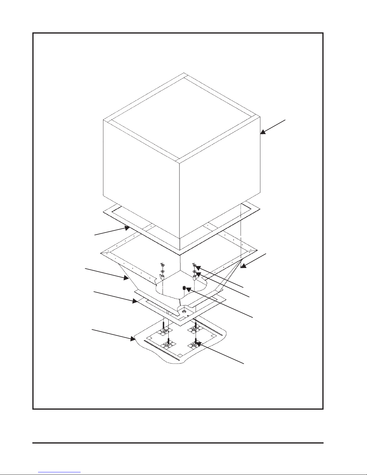
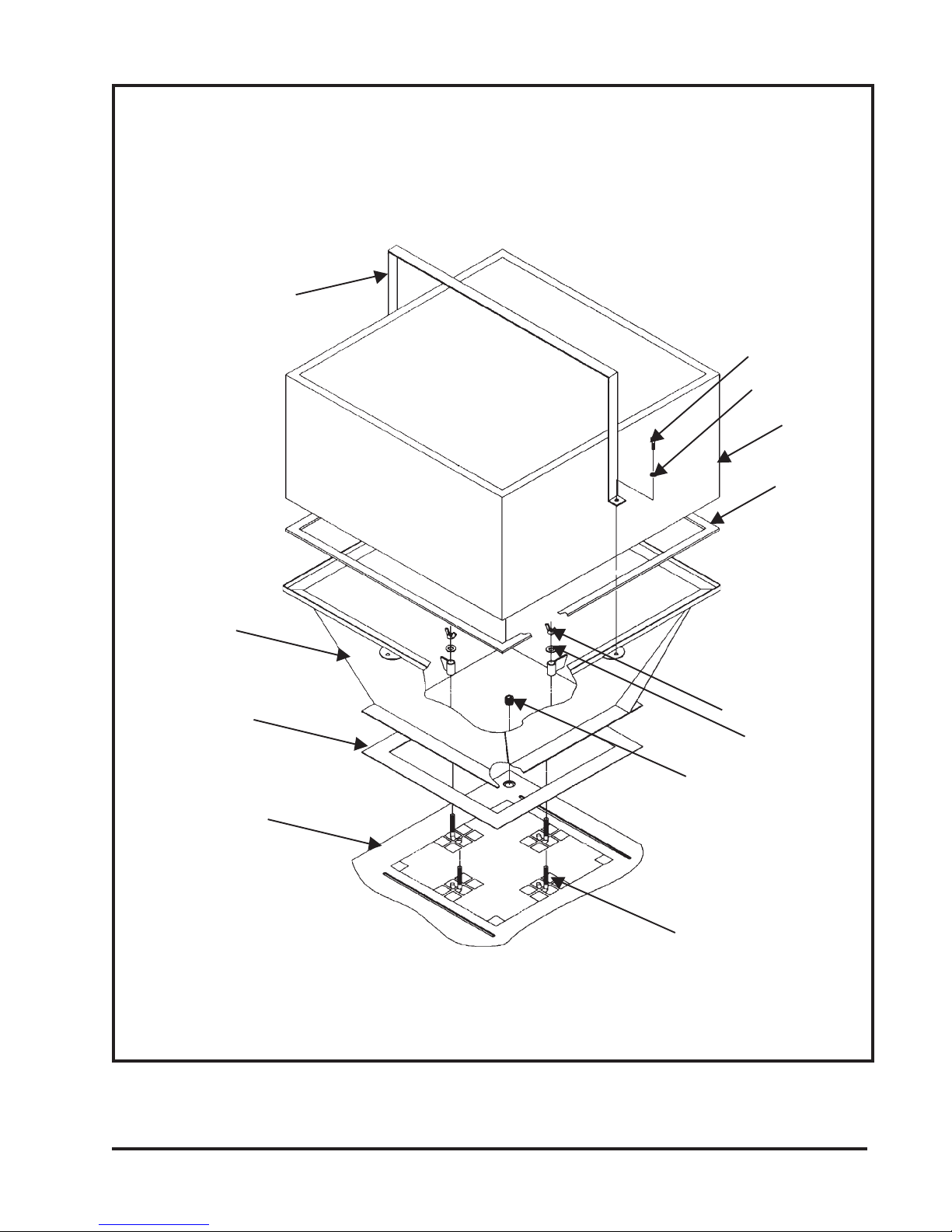
2.5.10 Bin Vent Base Pack
(See Figure 11 Bin Vent Base Pack)
The Bin Vent pack for the SDF consists of a
base, as shown in Figure 11 Bin Vent Base Pack.
The Bin Vent base has twenty-eight (28) 1/2"
diameter holes for attachment in the field.
14
Donaldson Company, Inc. © 1995
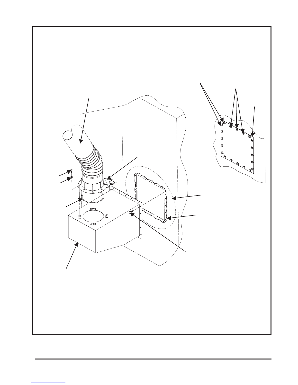
5/16 Screw
5/16 Washer
1/4" Diameter
Sealant
Flex-Trunk Assembly
(7-Foot Shown)
~
Swivel Base
M-6 Hex Bolts
(8 Req'd)
See Detail A
1/4" Diameter
M-6 Thread Cutting
Bolts (12 Req'd)
Cover Plate
Detail A
Sealant
Flex-Trunk
Adapter
Flex-Trunk Assembly 7-Foot/10-Foot SDF
Donaldson Company, Inc. © 1995
Use the bolts that are
removed from the cover
plate in Detail A
Figure 12
15
2.5.11 Flex-Trunk Assembly 7 Ft/10 Ft
(See Figure 12 Flex-Trunk Assembly)
Remove the cover plate bolts and the cover
plate from either the right or left side of the SDF
cabinet. Using the same cover plate bolts, attach
the Flex-Trunk Adapter to the side of the SDF
cabinet. Be sure to place 1/4" diameter sealant
between the adapter and the cabinet, as shown
in Figure 12 Flex-Trunk Assembly. Next, attach
the Flex-Trunk assembly to the adapter, being
sure to install more 1/4" sealant between the
adapter and the Flex-Trunk assembly. With the
swivel base positioned as shown in Figure 12
Flex-Trunk Assembly, secure the Flex-Trunk to
the adapter using the four (4) 5/16 slotted
screws and lock washers. For the adjustment
and operation of the Flex-Trunk, see the
Installation and Operation Manual for the FlexTrunk IOM-40779-00.
2.5.12 Weatherhood Pack
(See Figure 13 Weatherhood Pack)
Remove the bolts and the rear access panel to
the SDF. If the SDF is equipped with an outlet
damper (see Figure 1 SDF-4 Phantom View), this
damper must be removed. The weather hood
cannot be used with the outlet damper. Also,
remove the lift lug from the corner of the cabinet
and replace it with the M-16 set screw provided.
Place 1/4" diameter sealant between the cabinet
top and the weatherhood. Position the
weatherhood over the cabinet outlet, as shown
in Figure 13 Weatherhood Pack, and attach the
weather hood to the cabinet using the four M-6
bolts provided. These bolts should be inserted
through the slots on the cabinet roof and
screwed into the weld nuts on the weatherhood.
Replace the rear access panel and bolts.
2.5.13 Explosion Vent Cabinet (See Figure 15
SDF-4 with Explosion Vents—Phantom
View)
When explosion vents are furnished on an SDF,
a special cabinet is required (see Figure 15 SDF4 with Explosion Vents—Phantom View). Some
features on this cabinet include:
• A hinged access door to the dust container
with threaded handles and a reinforcing
bar.
• Two 1/8" NPT couplings for dirty air (high
pressure) and clean air (low pressure)
fittings.
• Two 3/4" NPT couplings for electrical
connections.
• Openings for two 12 x 12 explosion vents.
Options available with this SDF cabinet in
addition to the 12 x 12 explosion vents include:
• Explosion-Proof Motors.
• Aluminum Blower Wheels.
• NEMA 9 Explosion-Proof Solenoid
Enclosures.
• Checker board in remote enclosure with
unwired electrical only.
NOTE
• Explosion vent SDF units do not
contain an electrical compartment.
They are furnished from Torit
unwired.
16
• All electrical work must be done by a
qualified electrician according to local
codes.
Donaldson Company, Inc. © 1995

1/4" Dia Sealant
Weatherhood
Cabinet Shown with
Rear Access Panel
Removed
Donaldson Company, Inc. © 1995
M-6 Bolt
Replace Lift Lug
with Set Screw
Figure 13
Weatherhood Pack
17
 Loading...