


Operating Instruction
MML
High Pressure Centrifugal Pump
PT. TORISHIMA GUNA INDONESIA

I. Introduction
Our machines are very high quality products, which will always give you completely satisfactory and trouble free service, if they
are erected, serviced and operated properly by skilled personnel. The instructions and recommendations contained in this booklet
should be carefully followed to obtain trouble-free operation, and it should be accessible to everyone in charge of the erection, operation
and maintenance of the machines. We shall gladly supply further copies on request.
Please get in touch with us if you require any expert advice. We shall be glad lo oblige, and this also applies to any repair work
which may be required, and which you may prefer to entrust to us. We can pr ovide t he services of a skilled fitter on re quest, or you may
prefer to send the machine back to our works for repair.
If the instructions contained in this booklet are followed, you will be covered by the guarantee con tained in our conditions of
supply.
Our guarantee will however become void, if the machine is used to pump liquids or media other than those specified in the
confirmation of order, and at higher operating temperatures; if damage is caused to the machine as a result of improper manipulation,
operation outside the operating range specified, the use of unsuitable operating materials, faulty erection, wrong or unskilled laying of
the pipelines, etc.
During the validity period of the guarantee, any dismantling of the machine or its components may only be carried out after
receiving our previous consent in writing.
- 1 -

Contents
1.
2.
2.1.
2.1.1.
2.1.2.
2.1.3.
2.1.4.
2.1.4.1.
Introduction
General construction of pump
Description of pump
Casing
Rotating assembly
Bearings
Stuffing boxes
Soft packed stuffing boxes
Page
1
2
2
2
2
3
3
3
2.1.5.
2.1.6.
2.2.
2.3.
3.
3.1.
3.2.
3.2.1.
3.3.
3.4.
3.4.1.
3.4.2.
3.5.
3.5.1.
3.5.2.
3.5.3.
4.
4.1.
4.2.
Coupling
Foundations
Driver
Mode of operation of pump
Erection
Erecting the pump
Fitting and dismantling the coupling
Aligning the coupling
Instrumentation
Piping
Suction piping (suction lift piping or positive suction head piping)
Discharge piping
Valves and fittings
Valves and fittings in suction line (suction lift line or positive suction head line)
Valves and fittings in discharge line
By-pass non-return valve
Operating instruction
Commissioning and starting up the pump
Supervision during running
5
5
6
6
7
7
8
8
9
9
9
10
10
10
11
12
13
13
13

4.3.
4.4
4.4.1.
4.4.2.
4.4.3.
4.4.4.
4.4.5.
4.5.
4.5.1.
4.5.2.
4.5.3.
4.5.4.
4.5.5.
4.5.6.
4.5.7.
5.
5.1.
5.2.
5.2.1.
5.2.2.
Shutting down the pump
Maintenance
Maintenance of pump
Maintenance of soft-packed stuffing boxes
Maintenance of mechanical seal
Maintenance of bearings
Maintenance of balancing device
Operating troubles : causes and remedies
Pump does not deliver rated capacity
Driver is overloaded
Pump discharge pressure is excessive
Pump leaks
Stuffing boxes leak
Excessive bearing temperature
Excessive wear of balancing device
Dismantling and reassembling the pump
Dismantling
Reassembly
Reassembly of pumps with O-ring seals
Reassembly of pumps with metal to metal sealing faces
14
14
14
14
15
16
17
18
18
19
20
20
20
21
21
22
22
23
23
24
5.2.3.
5.3.
6.
7.
8.
Assembling the bearing
Protection of pump during prolonged shut downs and transport
Spare parts
Stub shaft dimensions, packing details, cooling water and oil
requirements, bearings, seals, gasket and O-rings
List of components and sectional drawings
24
25
25
26
27

2. General construction of pump
2.1. Description of pump
MML pumps are normally employed where the total head ranges from 215 to 710 Ib/in2 = 15 to 50 kg/cm*. The size designation
is in accordance with the bore of the discharge flange, e.g. MML 40 has a discharge bore of 40 mm = 1.5 in, etc. Constructional details
are shown in the sectional drawings at the end of this booklet.
2.1.1. Casing
MML high pressure pumps are multistage centrifugal pumps, with a radially split casing. The casing consists of the suction and
discharge casings (see sectional drawing, page 28, part Nos. 1060 and 1070) and of a number of intermediate, or stage casings
(IOSO). The individual casing components are clamped together by tie bolts (9050).The intermediate casings and tie bolts are encased
in a sheet steel cladding, and pumps which are intended for very hot liquids have a layer of insulating material underneath the cladding.
The diffusers (1710) are inserted between each successive pair of intermediate casings. The stuffing box housings (4510), and bearing
brackets (3500) are flanged onto the suction and discharge casings by studs. If the nature of the fluid pumped and the op erating
conditions permit it, the casing components are made of high grade cast iron. Where necessary, bronze, cast steel or chrome steel are
used for these components. The diffuser are made of cast iron, bronze or chrome steel, as required.
A leak-proof joint between the individual casing components is ensured by inserting rings (4120.5) profile seals, gaskets, or by
providing ground metal-to-metal joints, according to the operating temperature, and the material of the casings. In the latter case, the
pressure necessary to seal the metal-to-metal faces is provided by correct tensioning of the tie bolts.
The suction and discharge casings include integrally cast feet, the position of which varies according to the execution and
application of the pump and the temperature of the liquid; usually the feet are at the bottom of the casings, but for elevated operating
temperatures they may be at shaft centerline level in order to obviate any damage due to uneven expansion in the pump. Rene wable
case wear rings (5020) are fitted to the suction casing and intermediate stage casings, which can be renewed when the wear has
become excessive.
2.1.2. Rotating assembly
The shaft (2100) transmits the torque generated by the driver, in equal proportions to all the impellers, via the impeller keys.
The spacer sleeves (5251, and 521 or also 5252 on pump sizes 150 and above), e nsure the correct axial location of the impellers and
also act as shaft protecting sleeves. The correct axial position of the whole rotor assembly is maintained by the balance disc (6010),
which also absorbs the axial thrust. The shaft protecting sleeves ( 5240.1, 5240.2 ) provided to protect the shaft where it passes
through the stuffing box packing are screwed on to the shaft, one having a left-hand and the other a right-hand thread.
Fig. 2
- 2 -

The shaft (2100) is made of Siemens-Martin steel, or in certain cases, of special quality steel. The impellers (2300), shaft
protecting sleeves (5240.1, 5240.2), spacer sleeves (5251, 5210) and the balance device can be supplied in cast iron, bronze, carbon
steel or chrome steel according to the nature of the fluid pumped and operating conditions.
2.1.3. Bearings
The rotor assembly in MML pumps sizes 40 to 150 inclusive runs in two anti-friction bearings; from MML 200 and upwards two
plain bearings are used. The bearing brackets (3500) flanged to the suction and discharge casings are identical in dimensions. The
rotor assembly is afforded a small amount of axial float by the plain bearings and also by the anti-friction bearings, which are NU series
taper lock sleeve cylindrical roller bearings (3220).
All bearings are lubricated with oil, the plain bearings having oil rings. The over-flow hole drilled in the bearing end covers
(3600,3610) provides a means of checking the oil level (see section 4.4.4.) .
The table in section 7, (page 29) gives a summary of the various types of anti-friction bearings fitted in these pumps.
2.1.4. Stuffing boxes
The purpose of stuffing boxes is to prevent high-pressure liquid from escaping through the gap between shaft and casing, or the
entry of air into the pump, if the pump suction is at less than atmospheric pressure.
Whether conventional soft-packed stuffing boxes or mechanical seals in one of the many types available are used, will depend
on the pressure, temperature and nature of the liquid pumped.
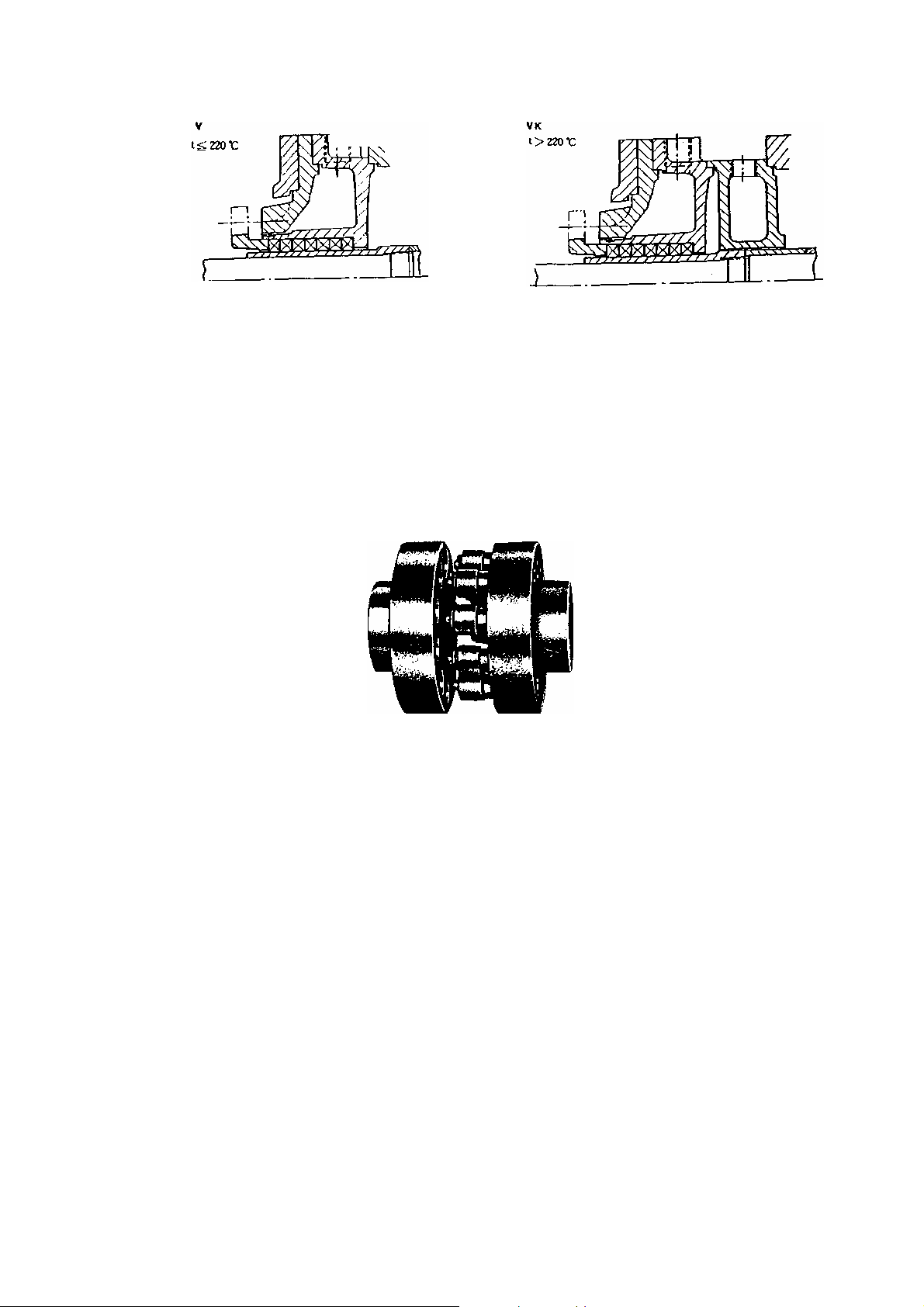
2.1.4.1. Soft-packed stuffing-boxes
Soft-packed stuffing boxes rely on rings of soft-packing as the sealing element; successive packing rings are inserted in the
annular space between the stuffing box housing (4510) and the shaft protecting sleeve (5240.1 or 5240.2), and are lightly pressed in
position by the stuffing box gland (4520). The standard stuffing box in fig.3 top left, is quite adequate for sealing clean wat er under
pressure at temperatures not exceeding 220°F (105 °C). When the temperature exceeds 220 °F, the so-called hot water execution HW,
with hot water stuffing boxes is used (fig. 3). With this type, an end cover (304) is mounted between the bearing brac ket (350 0) and t h e
stuffing box housing (4510).
The stuffing box housing (4510) surrounds the shaft protecting sleeve (5240.1 or 5240.2) and can be flushed with cooling water,
thus ensuring that the hot water from the pump is effectively cooled in the narrow annulus up-stream of the packing rings, and its
temperature considerably reduced before it reaches the packing rings. A prerequisite for effective cooling of the water which reaches
the stuffing box is that the packing rings them selves are in good condition and provide an effective seal. The pressure at the stuffing
box is not affected by this gap or annulus.
A part from these standard stuffing boxes, there are SPECIAL TYPES recognizable from the fact that the space for the packing
is extra long, to provide room for an increased number of packing rings, and usually also a lantern ring, which may be located at the
bottom of the box, or amid the packing rings, according to requirements. This lantern ring forms a means of preventing the ingress of
liquid from the interior of the pump; this is effected by drilling a passage in the housing (4510) in register with the ring, and passing
through it a sealing liquid (e. g. water from the discharge side of the pump) ; in certain cases, leakage fluid ma y be led off by means of
this lantern ring.
If the temperature of the liquid handled by pumps with special stuffing boxes exceeds 220 °F, a cooling chamber 301 (fig. 3) is
fitted up stream of the stuffing box to cool the liquid flowing from pump to stuffing box, the action being similar to that of the HW
execution described above.
Fig.3 illustrates the various special stuffing boxes V, VSH and VSM with or without cooling chamber (301) for a variety of liquids
pumped.
The maintenance of soft-packed stuffing boxes is described in section 4. 4. 2.
- 3 -

Stuffing Box Conventional Types Cooling Liquid
HW 105 °C<t<220°C
Stuffing Boxes Special Types
Medium Compressed :
For liquids with entrained abrasive particles, when the packing must be protected againts the penetration of any abrasive
materials ( e. g. oil with Kieselgur, fractions from the catalytic cracking plan with entrained abrasive particles).
Sealing, resp, leakage liquid
Medium Compressed :
For liquid that have to be drawn off under vacuum, (e. g. hydrocarbons and oils that are vapori zed in vacuum, residues in
vacuum columns, condensate). When stuffing box losses must be trapped before they reach the open, the liquid (e. g. all kinds
of solvents, ammonia) are led off through the lantern ring into closed vessels.
- 4 -
Cooling or heating liquid
Medium Compressed :
For LPG, expect liquefied propone below 130 °F (55 °C) above lubric ant and heat transfer media (e. g. Down
them) below 360 °F (180 °C) above.
Fig. 6. Flexible Coupling
2.1.5. Coupling
The pump and driver are connected to each other by a flexible coupling. Fig. 6 illustrates the type of flexible coupling most
frequently used. All couplings demand very careful alignment of the pump and driver shafts, because any misalignment
(whether radial or angular) can only be absorbed to a very limited extent by the rubber or elastic members of the coupling at the
prevailing operating speeds see section 3.2).
2.1.6. Foundation
When we supply a complete pumping set, including motor and combined base plate, we only bolt and dowel the pump on to
the base plate at our works, after having aligned it with the motor. We do not dowel the driver, because the combined base
plate cannot, for economic reasons, be constructed so rigidly that it will not distort to a certain extent during transport, or it is set
on an uneven foundation. It only attains its ultimate stability after having been placed on the foundation and grauted in with a
cement mixture. Therefore, the pumping set must be levelled up with the aid of shims and carefully aligned afresh after erection
at side (see section 3.2.1) and, only after this has been done, should the driver be dowelled in place.
- 5 -

2.2. Driver
The driver is usually coupled to the suction end of the pump. Pump rotation is clock-wise viewed from driver. On special
request, the pump can be supplied with the stub shaft at the discharge end (in this case, rotation is anti-clockwise viewed from
driver) or with stub shafts at both ends. The variety of drivers which can be used is so great that it would be impossible to
describe them all in the context of this booklet; therefore we refer you to the operating instruction manual supplied by the
manufacturer of the driver.
2.3. Made of operation of pump
The fluid flows through the suction casing (1060) at a given pressure, onto the first stage impeller (2300). A certain amount
of energy is imparted to the fluid in the impeller, which is provided with a number of vanes. The fluid then flows out of the
impeller into the diffuser (1710), where a partial conversion from kinetic energy into potential energy takes place, res ulting in a
further increase in pressure. The return guides in the diffuser then lead the fluid onto the eye of the following impeller. This
process is repeated from stage to stage, and at each stage the pressure increases by the same amount, i. e. the stage head.
After leaving the final diffuser, the fluid penetrates into the discharge casing (1070) and thence into the discharge piping.
An axial thrust A ( see fig. 7 ) acts on every impeller; it is caused by the hydraulic pressure which acts on one side only of
the annulus with outside diameter Dςp (= seaIing clearance gap diameter) and inside diameter DA ( = o.d. of spacer sleeve).
This axial thrust A is transmitted to the rotor and is absorbed by a special hydraulic balancing device on MML series pumps.
This balancing device consists of a balance disc (6010) and a balance disc seat (6020), and it operates through the action of a
fixed area, or constant clearance gap (between the pump rotor and discharge casing) in series with a variable clearance gap
(between balance disc and balance disc seat). If, for instance, the variable clearance gap between balance disc and balance
disc seat is very narrow, this will result in a high pressure, equal almost to the full pump discharge pressure, acting on the
balance disc, and pushing the rotor axially towards the discharge end of the pump; the gap will consequently widen. If, on the
other hand, this gap is too wide, the increased flow of balance water which now flows through the balancing device will be
subjected to a greater pressure drop through the fixed area clearance gap, and consequently the thrust on the, balance disc will
decrease, causing the rotor to slide back towards the suction end of the pump. In operation, the rotor will therefore settle down
at a median position, corresponding to a median clearance gap between balance disc and seat.
Fig. 7
The balance water is either discharged to atmosphere, or (e. g. when the pump suction pressure is above atmospheric
pressure) returned to the suction casing of the pump or to the suction vessel through a separate line. The balancing device will
onto give trouble – free operation if the balance water is allowed to flow away without hydrant. Any isolating valves in the
balance water return line must be kept looked in the open position. The axial position of the rotor assembly can be checked on
the axial position indicator at the discharge end of the pump shaft (see section 4. 4. 5) .
-
-
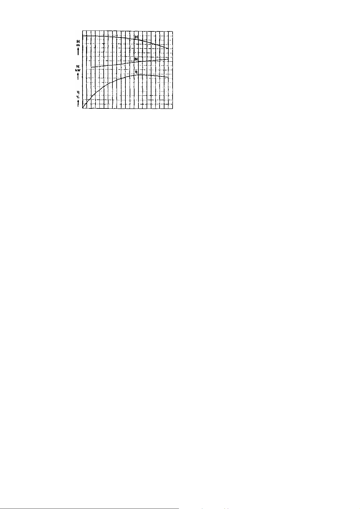
Fig. 8 Characteristic curves at constant pump speed
Fig. 8 illustrates the fact that the power absorbed by the pump does not decrease proportionately with the reduction in
pump capacity; on the contrary, the power absorbed at shut-off head (capacity Q = O) is quite considerable. This absorbed
power is transformed almost wholly into heat within the pump, and this will rapidly lead to over heating and vapor formation in
the pump, when it is operated for any length of time against a closed discharge valve, or at very low through puts; this is
particularly true in the case of powerful drivers and hot fluids (high pumping temperatures). In order to prevent vapor formation
which could endanger the pump, it is essential to ensure that a certain minimum flow always passes through the pump and
carries off the internally generated heat. For this purpose, we recommend the provis ion of a BY-PASS NON-RETURN VALVE,
or automatic leak-off valve (see fig. 14 and 14 a), which automatically opens a by-pass line when the pump capacity drops
below a certain figure.
If no such valve is incorporated in the installation, it is important to remember that the pump should never be operated
below a certain minimum flow, nor against a closed discharge valve. After running the pump up to operating speed against a
closed discharge valve, on start-up, the discharge valve should immediately be opened.
When pumping hot or highly volatile liquids, and when operating the pump under suction lift conditions, care should be
taken to ensure that the pressure at pump suction nozzle is adequate, i. e. at least as high as stated in the confirmation of
order; otherwise vapor formation and cavitation will occur, which may damage the pump, particularly the first stage impeller and
the balancing device. If the discharge pressure is lower than that for which the pump was designed, the capacity will increase
correspondingly and this may result in over loading the balancing device or the motor, which will run excessively hot.
3. Erection
1.1. Erection the pump
Correct and skilled erection on an adequate foundation is an essential pre-requisite for trouble-free operation of the
pumping set.
The following points should be scrupulously observed in order to avoid operating troubles and damage to the pump :
1. Make sure that the foundation has set properly before placing the pump on it.
2. Level up the base plate by means of packing or shims, with the aid of a spirit level.
3. Check coupling alignment for parallelism and concentricity, and re-align same if necessary, ( see section 3.2.1.).
4. Grout in the base plate and the foundation bolt pockets with a quick setting cement mixture in I : 2 ratio.
Make sure that no empty spaces or cavities are left beneath the base plate.
5. When the cement has set completely, tighten the nuts on the foundation bolts evenly and firmly.
6. Connect the piping to the pump nozzles without imposing any stress or strain on the pump. Remember that pumps should
not be used as anchorage points for the piping.
- 7 -

7. After the piping is connected, the alignment at the coupling should be checked once again. It should be possible to rotate the
rotating assembly easily by hand on the coupling, if the stuffing boxes are not packed (see section 3.2.1).
8. Dowel the driver (see section 2.1.6.).
9. Before the pump is started up for the first time, it is essential to check the direction of rotation of the driver, with the pump
uncoupled. Remember that even a short run in reverse rotation or a short period of dry running can result in serious
damage to the pump.
The correct direction of rotation of the pump is indicated by an arrow on the drive end bearing housing.
Turbine driven pumps should have their turbine over speed trip tested with the pump uncoupled.
Fig.9 Coupling Extractor
3.2. Fitting and dismantling the coupling
Flexible couplings should either be heated to 180 °C ( 350 °F ) approx, before fitting or removing, or this work should be
done with the aid of a suitable coupling extractor ( see fig. 9 ). Never drive the coupling onto the shaft with a hammer.
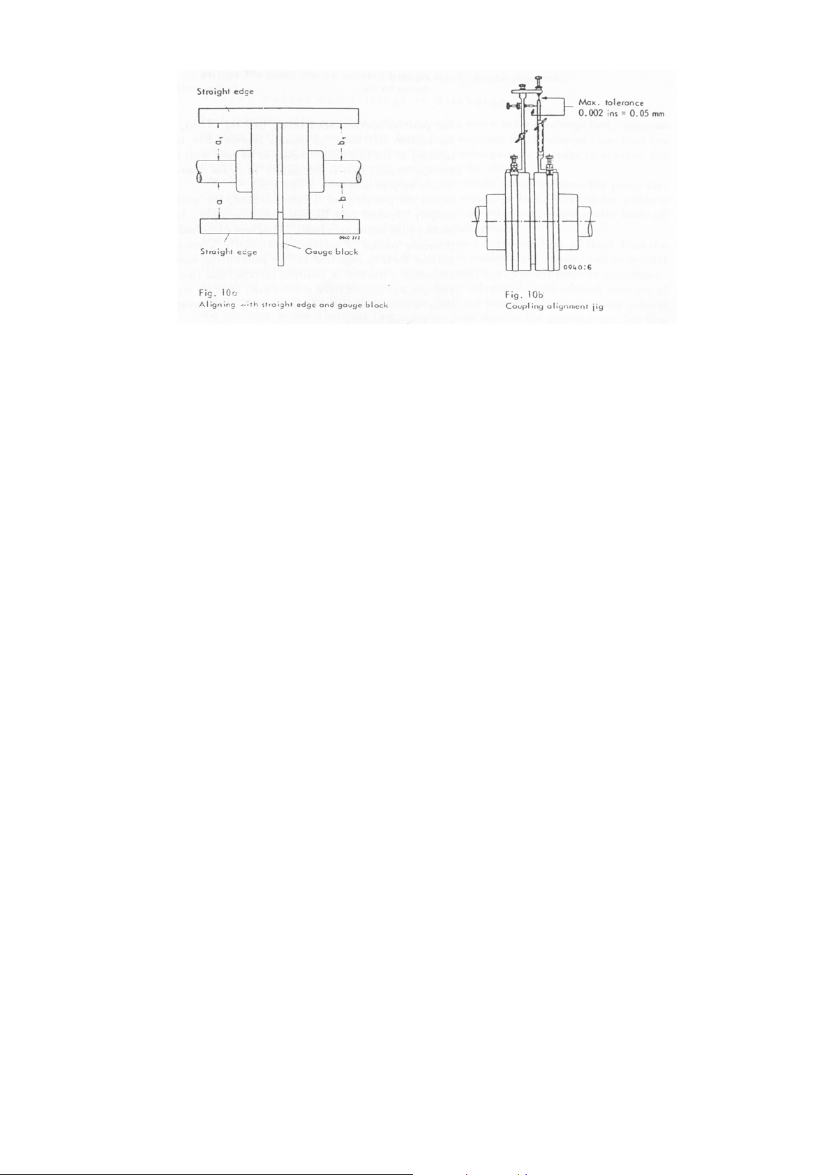
3.2.1. Aligning the coupling
Faulty alignment will result in damage to the flexible components of the coupling, and will also damage the pump and motor
bearings.
In order to align the shafts, the pump and driver are set on the grouted-in bed plate as shown on the General Arr angement
Drawing, and pushed towards one another until the pre-scribed gap between the two coupling halves has been attained. Then
the coupling can be aligned by means of a straight edge and gauge block (fig. 10a) ; the coupling is correctly aligned ifa=a] and
b = bj; furthermore the axial gap between the faces of the coupling halves should remain the same right around the periphery of
the coupling.
We can supply a special alignment jig on request (see fig. 10b) which greatly facilitates coupling alignment. When this jig is
used, the coupling can be considered correctly aligned if the tolerance, both in the axial and radial planes measured at the tips
at four points around the periphery, at 90° intervals, does not exceed 0.05 mm in any case. This control should be repeated
after connection of the pipelines.
-
-
3.3. Instrumentation
In order to facilitate operating supervision, we recommend that each pump be provided with pressure gauges (with large
dials) at the suction and discharge nozzle and on the balance water line. These gauges should incorporate a gauge cock or
valve. They should be mounted in such a way that they are exposed to the least possible amount of vibration.
3.4. Piping
It should be possible to connect the piping to the pump easily and without undue strain. Remember that any appreciable
forces transmitted from the piping to the pump and base plate will tend to up set the alignment of the set, and cause it to run
rough. To avoid any possible damage from this cause, hot water pipelines should be provided with adequate expansion loops.
Sharp bends and abrupt changes in cross-section should be avoided. If an increase in pipe cross-section is required, the to tal
angle of the taper piece (twice the angle between centre-line and wall of taper piece) should not exceed 12 °C. Make sure that
the gaskets of flanged connections do not protrude inside the pipe.
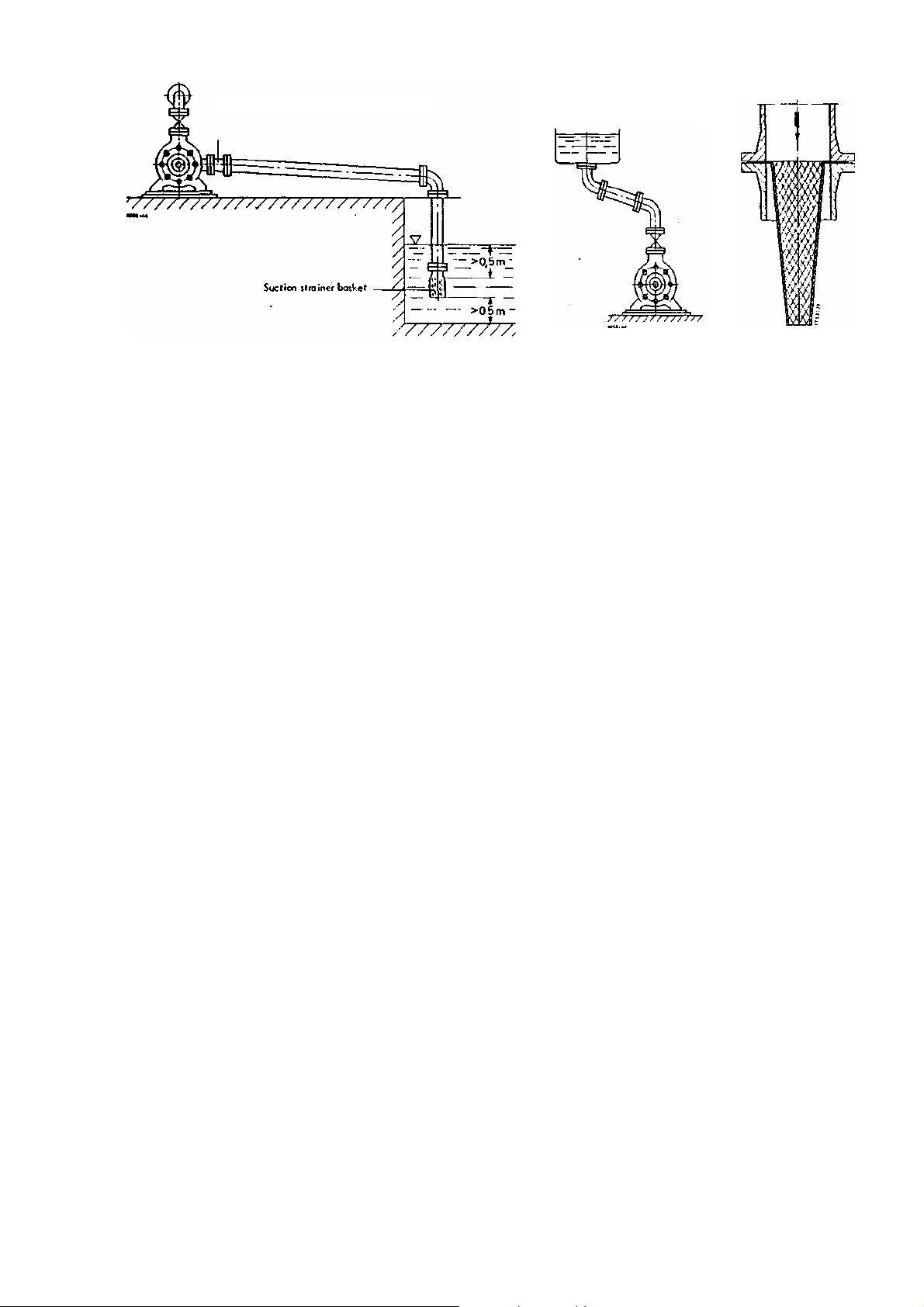
341. Suction piping (suction lift piping or positive suction head piping).
The suction piping connected to the suction casing is designated either as suction lift piping or as positive suction head
piping (flooded suction), depending on whether the suction pressure upstream of the pump is below or above atmospheric
pressure. In either case, the suction piping should be kept as short as possible. Suction lift piping (see fig. 11 a) should be laid
with a rising incline towards the pump, should be absolutely leak tight, and not present any features tending to promote the
formation of air pockets.
The nominal size of the pump suction flange is no indication of the correct size of suction piping required for any given
installation. As a first approximation, the suction line should be sized to give a flow velocity not exceeding 2 m/sec, (6 ft/sec). It
is desirable to provide a separate suction line for each pump ( in a pumping station comprising several pumps ). If this is not
possible for practical reasons, the common suction line should be sized for as low a flow velocity as practicable, and this velocity should preferably remain constant right up to the last pump on the line. If the suction pipe is to be laid in an underground
trench, it should be hydrostafically tested at 3-4 Kp/cm2 (40 to 60 PSIG) before being buried.
-9 -
Eccentric reducer (fitted belly down)
Fig.11a Suction lift line
For positive suction head lines, (see fig. 11b), the same considerations apply as for suction lift lines, as regards features
and laying of the line. The horizontal sections of the line should however be laid with a gently rising incline towards the suction
vessel. If it is impossible to avoid apexes in the suction line, each apex should be provided with a vent cock.
Before the pumping set is commissioned, the suction lines and vessels must be thoroughly cleaned and flushed.
Unfortunately, foreign matter, including welding beads, pipe scale etc. tends to become detached from the piping only after a
considerable period of service, particularly when a hot fluid is pumped. In order to prevent these foreign bodies from penetrating
inside the pump, it is necessary to incorporate a strainer in positive suction head lines.
This strainer should have a total area of holes equal to three to four times the pipe cross-section, in order to avoid too great
a pressure drop when it becomes choked with foreign bodies.
Conical strainers of the type illustrated in Fig. 12 have proved very satisfactory for this purpose, and are recommended;
they should be made of corrosion-resistant materiaI.
The pressure at the pump suction nozzle should be checked at regular intervals. If it drops, this indicates that the suction
strainer should be removed and cleaned. After severer weeks of operation, when no more foreign bodies are anticipated, the
strainer can be permanently removed.
Fig. 11b
Fig. 12
3. 4. 2. Discharge Piping
The hydrostatic test pressure prescribed in DIN 2401 specification only applies to individual lengths of pipe and not to the
complete, finally assembled discharge line.
The latter is usually tested at a pressure equal to the maximum operating pressure anticipated.
Discharge lines are usually sized for flow velocities of 3 m/sec. (10 ft/sec).
3. 5. Valves and fittings
Only those valves and fittings (i.e. isolating or control valves, non - return valves and check valves) are described here
after, which are incorporated in the suction line, or close to the pump itself in the discharge line.
3.5.1. Valves and fitting in suction line (suction lift line or positive suction head line).
Isolating valves in the suction lift line or the positive suction head line are solely intended to isolated the l ine. They
must always be kept fully open while the pump is running.
- 10 -

An isolating valve should only be incorporated in a suction lift line, if more than one pump is connected too common suction
line. In such cases, the valve should be installed with its stem horizontal, or pointing vertically downwards, to prevent the
formation of air pockets.
If this proves inconvenient, and the valve has to be installed with its stem vertically upwards, it should be provided with a
sealing water connection, or a so called water cup, to prevent the ingress of air through the gland on the valve stem.
Pumps lifting from a suction tank or suction pit should have a strainer basket fitted to the mouth of the suction line, in order
to keep coarse impurities away from the pump.
The strainer basket is usually combined with a foot valve, which enables the suction lift line to be primed with fluid before
starting the pump (see fig. 13). The strainer basket should be installed at least 0.5 meters (18 ins.) below the minimum water
level in the pit, and at least 0.5 meters (18 ins.) above the pit floor, to prevent either air or sand or sludge being entrained into
the pump (see fig. 11 a) .
Fig. 13 Suction strainer basket with foot valve
Positive suction head lines should preferably be provided with an isolating valve, so that the pump can be isolated from its
supply source required.
3. 5. 2. Valves and fittings in discharge line
Each pump should be provided with an isolating valve in the discharge line, situated as close to the pump as possible. A
part from isolating the discharge line from the pump, this valve can be used to throttle the discharge flow in order to achieve the
desired operating duty or to avoid over loading the driver.
We also recommend the installation of a non-return valve between the pump discharge nozzle and the isolating valve in the
discharge line. This can be either a check valve, a non-return valve, or by-pass non-return valve (automatic leak-off valve) - see
section 3.5.3., according to requirements.
The object of the non-return valve is to prevent a reverse flow of fluid from the discharge line into the pump, when the latter
is suddenly shut down, and to protect it from possible damage arising from water hammer, i.e. violent pressure pulsations.
A sticking or leaky non-return valve or check valve will cause reverse rotation of the pump and may result in damage if the
shaft nut becomes slack. This may arise if the pressure in the discharge line is higher than that in the positive suction line when
the pump is stopped, causing reverse flow of the fluid.
Please note that these reverse rotation speeds can attain very high values, especially when the pump is pumping against
an air or gas cushion. In this event, gas will penetrate inside the pump and expand there.
It is recommended to provide two non - return valves in series in such cases.
3.5.3. By-pass non-return valve
The by-pass non-return valve, or automatic leak-off valve is a safety device, the purpose of which has already been
described in section 2.3. It is fitted in close proximity to the pump, always between the pump and the isolating valve in the discharge line (never down-stream of the isolating valve).
- 11 -

It must always be installed vertically, with the direction of flow from bottom to top. Its construction and mode of op eration is
illustrated in fig. 14 and 14a,
No.
1 Body
2 Cover
3 By-Pass Outlet
5 Bearing
7 Cover
16 Seal
19 Venturi
23 Rocker Guide
24 Rocker
29 Arbor
30 Washer
31 Slide
36 Bolt
37 Stud Bolt
Name of Part
38 Nut
39 Blind Flange
40 Seat packing
41 Sest Packing
Each by-pass non-return valve is selected and supplied for the particular operating conditions pertaining to a given pump.
The lift of the by-pass non-return valve cone increases as the rate of flow approaches its maximum. The slide valve rod
connects the valve cone with the slide valve of the by - pass outlet. When the valve cone lifts, the slide valve slides, closing the
by - pass when a given minimum flow is exceeded, resp. opening it when the flow drops below the minimum.
The minimum rate of flow, at which the valve opens, is selected large enough to obviate undue overheating within the pump
(section 2.3.).
- 12 -

4. Operating instructions
4. 1. Commissioning and starting up the pump
A. Points to be checked prior to commissioning or start-up:
1 .Check the oil level in the bearings of the pump, and if necessary replenish until the oil runs out of the over flow.
2. Check the condition of stuffing boxes. Follow the instructions for correct packing of the stuffing boxes.
3. If cooling water is provided, turn it on and check that if flows away freely.
4. Close discharge valve; check that isolating valve in the balance water line is wide open.
5. Open valve in suction line to its full extent.
6. Make sure that the pump is completely primed with liquid. Priming is effected through the priming tundish (with valve) or
by opening the by-pass on the non return valve. Watch the pressure gauge on t he suction casing - the pressure in the
suction line should not be allowed to rise excessively during priming. While priming takes place, the shaft should be
rotated repeatedly by hand and the vent cock on the suction casing should be opened.
7. When operating with positive suction head, check pressure and temperature in the suction line.
8. If a non-return valve is fitted, and the pump has to be started with the discharge valve open, check that the non-return
valve is closed by the pressure in the discharge line ( e. g. boiler pressure ) on start-up. If the full discharge pressure
does not reign in the discharge line before start up, the pump should only be started against a closed discharge valve.
B. Start Up
1. Switch on driver for a short instant, then switch it off again immediately. Observe the rotor, which should run down to a
standstill evently and smoothly. Check that the bearings are being properly lubricated.
2. Run the pump rapidly up to full speed.
3. Check that the pump attains the prescribed discharge pressure.
4. After the pump has attained full operating speed, open discharge valve and adjust it to the operating conditions required.
4.2. Supervision during running
1. The pump should run quietly and without vibration at all times.
2. Check the bearing temperature at regular intervals (it should remain steady). If it rises unduly, check condition of
bearings.
3. Watch the stuffing boxes; the glands should drip slightly during running.
4. If water cooling is provided, check the cooling water outlet temperature at regular intervals; a 10 °C (50 °F) temperature
difference between cooling water inlet and outlet is acceptable.
5. Avoid over loading pump and driver (this happens when the discharge pressure drops below the design figure).
6. Check the correct functioning of the by-pass non-return valve; the by-pass should open at lo w through puts. This can
be observed by touching the by-pass return line, which should become warm.
7. If the pump operates on suction lift, always ensure that the suction head is adequate, and that no air is entrained into the
pump, by checking the water level in the suction pit or vessel.
8. If the pump operates with positive suction head, always ensure that this head does not drop be low the figure specified in
the confirmation of order, as serious damage to the pump internals might otherwise result, due to cavitation. For the same
reason, the suction temperature should never be allowed to exceed the maximum value specified. This point should be
watch particularly carefully if the pump is used for hot water duty.
9. Check the pressure in the balance water line and the shaft position the position indicator at the stub end, at the regular
intervals.
10. If standby pumping sets are installed, it is advisable to operate all the pumps on a rotation system thus giving each pump
in turn a certain amount of operational duty; this ensures that the standby pump will always be in good condition for
instant start-up if required.
- 13 -

4. 3. Shutting down the pump
1. Close discharge valve.
2. Switch off driver, and observe pump rotor running down to a stand still.
3. Turn off cooling water, when the pump has cooled down below 105 °C (220 °F).
This only applies to pumps with cooled stuffing boxes or bearings.
4.4. Maintenance
The pump and driver must be kept under careful observation the whole time the set is running.
4.4.1.Maintenance of pump
We recommend keeping a log book in which the operation of the pump should be regulary recorded. The data recorded
should include pump capacity, suction and discharge pressures, balance water pressure, water temperature, bearing
temperature, and pump speed, as well as the operating data of the driver (output and speed of electric motor, diesel engine or
turbine). The switching on and switching off times should also be recorded to enable the total number of operating hours of the
pump to be ascertained at any time.
A further column for "remarks" should be provided, in which details of maintenance and repair work can be entered. This
log book will thus enable a clear picture of the condition of the pump to be kept at all times.
Pumps erected on new foundations should be subjected to an alignment check at the coupling from time to time, to
ascertain whether any settlement in the foundations may have resulted in misalignment of the pumping set. This check should
also be recorded in the log book.
Actual maintenance of the coupling is restricted to periodical inspection of the rubber components or flexible members and
their renewal when necessary. Rubber parts should be kept well clear of contact with oil or grease.
4.4.2. Maintenance of soft-packed stuffing boxes.
The stuffing boxes will give trouble - free and satisfactory service providing they are carefully and correctly packed and
maintained. The pumps are delivered with their stuffing boxes unpacked, and one set of packing for each box is included in the
consignment. Before packing the box, the packing compartment and shaft sleeve should be thoroughly cleaned. The individual
rings should be cut from the packing coil with a clean scarf joint, stretching the coil flat in a wooden jig, as shown in Fig. 15. The
rings must be cut to the correct length, so that the ring butts are in light contact with each other at the scarf joint, when the ring
is wrapped around the shaft protecting sleeve.
If the rings are cut too long, they will bulge out at the joint; if they are too short, there will be a gap at the joint. In eithe r case, the
stuffing box will leak as a result.
- 14 -
Fig.16 Stuffing Box and Packing Rings

Before insertion in the stuffing box, cotton vibration packing rings must be thoroughly soaked in oil, but asbestos vibration
packing rings should only be coated with oil on the inside. The first ring is wrapped around the sleeve and carefully pushed to
the bottom of the pacing compartment by means of the stuffing box gland. The following rings are then inserted one by one, and
the butt joint of each ring should be offset approximately 90 ° from the preceding one; the gland is used to push each ring in
position (see fig. 16). The rings should only be pressed lightly against each other by the gland. Only insert as many rings in the
compartment as will leave a clear gap at the end, of at least 5 mm (1/4"), for the positive guidance of the gland, to prevent it
being tightened askew. This would result in scoring and damage to the shaft protecting sleeve by the gland.
In some pumps, there is a lantern ring in the stuffing box, which latter then bears a plate indicating the position of this
lantern ring. It must be located opposite the hole drilled in the stuffing box housing, through which sealing liquid may enter, or
leakage fluid may flow out. The pressure of the sealing liquid must be a little higher than the pressure in the stuffing box; this is
arranged by tapping the liquid from the appropriate stage in the pump.
When all the packing rings have been inserted, the gland is fitted, and the gland nuts tightened lightly by hand. A newly
packed stuffing box will leak appreciably at first. If this leakage does not cease of its own accord after the pump has been
running a few hours, the gland nuts should be tightened slowly and evenly on either side, while the pump is running, until the
gland only drips slightly; this indicates that the packing is functioning correctly. If the stuffing box does not leak at all, or if it
starts to smoke, loosen the gland nuts slightly.
Every newly packed stuffing box needs a certain running-in period before it settles down, and it should be kept under
constant observation during this period. After settling down, it need only be checked occasionally.
After a prolonged period of service, when the existing packing has been compressed by approximately the width of one
packing ring (by repeated tightening of the gland nuts), it is time to renew the packing and to check the condition of the shaft
protecting sleeves on this occasion. If the latter show signs of grooving, scoring or surface roughness, they should be replaced
by new ones.
Packing obtained fresh from the manufacturer should preferably not be used; packing which has been kept in store for a
period has a longer life. We therefore recommend keeping an adequate supply of spare packing in stock at all times. Onl y use
absolutely clean water for cooling the stuffing box housings (on cooled stuffing boxes). Sludge and lime deposits will seriously
hinder heat transfer and render the cooling almost inoperative. We recommend thoroughly cleaning out the cooling chambers
from time to time.
The cooling water should be allowed to flow away freely and visibly, so that its temperature and flow rate can be checked at
any time. The temperature difference between cooling water inlet and outlet should not exceed 10 °C (50°F). The cooling water
supply lines should be provided with isolating valves, to enable the cooling water flow to be adjusted as required, and to be
turned off when the cooling chambers and covers are cleaned.
Always turn on the cooling water before starting up the pump, and only turn it off again after the pump has stopped, (see
4.3., effect of temperature).
4.4.3. Maintenance of mechanical seals
Before starting the pump for the first time, check that the flow controllers (see section 2.1 .4.2.) or the needle valves in the
circulation line are fully open. The pressure in this line should be 30-55 PSI above the positive suction head pressure; the
appropriate tapping from the pump is already provided. After a running-in period of several hours, the coolant flow through the
controllers can be gradually reduced by means of the adjusting screw.
The flow is adequate when the temperature of the seal housing is not appreciably higher than that of the other parts of the
pump, in cases where the circulation fluid is tapped from the stream of liquid pumped, without any i nter cooling. This temperature should be checked by feel from time to time, and if the housing becomes unduly hot, the flow controller should be opened
fully. If this does not bring about a fall in temperature, the circulation line must be dismantled and cleaned out. In normal
operation, the gland of the auxiliary stuffing box, if one is provided, must not be pulled up tight. It is retained in a partially tight
condition by a special device (Fig. 17), and only when a leakage (due too defect in the mechanical seal) is observed, should the
pin be depressed and the gland tightened up by clock-wise rotation, or by tightening the stud nuts. The pump must then be
stopped, so that the defective mechanical seal can receive attention.
-
-

If the carbon rings and rotary rings have to be renewed, they should never be placed anywhere with their working faces
down, since even the slightest scoring of the highly finished surfaces may result in leakage.
Fig. 17 Auxiliary Stuffing Box
1758:15
4.4.4. Maintenance of bearings
Before the pump is first commissioned, or after it has been idle for a prolonged period, the oil level in the bearings m ust be
checked by dipstick or overflow, and its appearance should also be checked. It must not be cloudy (condensation!). Any topping
up of oil must be carried out with scrupulous cleanliness, filling being done through the oil cap on the bearing. If necessary, all
remains of the old oil can be completely drained off by unscrewing the drain plug, and cleaned out by taking off the bearing
covers (3600, 3610). Any flushing must be done with petrol, benzolle or wash oil.
The first oil change in a new bearing should be made after 200 hours of operation; subsequent changes after every 1,000
further hours of operation. Only use well known brands of lubricants for antifriction or plain bearings, to the following
specification:
Viscosity at 120 °F = 50 °C : 20 to 45 cSt ( Approx, SAE 10 W ).
Flash Point : 380 to 450 °F (195 to 230 °C)
Pour point, below : 15 ° F (-10 °C)
Ash content, below : 0.05 %
The temperature of the bearings, the oil levels, and the quiet running of the pump must be kept under careful observation
the whole time it is running. The temperature of the bearings must never exceed 175 °F (80 °C) and, with this as a m aximum, it
must never be more than 120 °F (50 °C) above ambient temperature. If the oil should become contaminated with water or any
other foreign matter, the pump must be stopped at once, and the bearings thoroughly cleaned and refilled with oil.
Any cooling of the bearings must be done with pure, cold water, and the remarks on cooling of stuffing boxes (section
4.4.2.) apply equally to the bearings.
4.4.5. Maintenance of the thrust balancing device
Trouble free operation of the pump is dependent on the correct functioning and good condition of the balancing device.
If an isolating valve is incorporated in the balance water line, it should always remain open while the pump is running,
irrespective of whether the balance water is discharged into the open, into a vessel, or returned to pump suction.
The working life of the balance disc (6010) and balance disc seat (6020) will depend, amongst other factors, on the n umber
of stops and starts of the pump during normal operation.
The wear on these components will cause the pump rotor to move gradually towards the suction end of the pump, Aft er the
wear has attained a certain limit, the danger will a rise of the pump rotor fouling the casing, particularly the wear rings (5020).
Therefore the position of the rotor shaft should be checked at regular intervals during running.
- 16 -

The shaft position indicator is situated on the bearing bracket at the discharge end of the pump ( see fig. 18). When the
pump leaves our works, the measuring edge or marking A on the shaft stub is adjusted to the median position o n the wear
indicator. The distance between adjacent markings is 1. 5 mm. When the measuring edge has moved axially towards the
suction end by an amount of 1. 5 mm approx., this indicates that wear is so severe that the balancing device must be inspected
and over-hauled. The worn components (6020, 6010) must be touched up or replaced b y new ones. If necessary, and the
measuring edge A must be reset.
On the occasion when the balancing device components are touched up or renewed, the radial clearances at the seaIing
gaps between rotating and stationary parts should be checked. A rough and ready method of doing this consists in raising the
rotor and measuring the resulting clearance, preferably close to the final stage impeller. Too great a clearance will upset the
axial thrust balance, and give rise to rapid wear of the balancing device. If necessary, the worn components should be replaced
by new ones.
The table below lists the clearances which should not be exceeded :
Clearance in millimeters ( on diameter )
Between impeller (2300) and wear ring (5020) 0.3 mm 1.2 mm 1.5 mm
Between spacer sleeve (5210) and diffuser
(1710)
Between spacer sleeve at suction end (5251)
and suction casing (1060) For suction lift
operation 01 atmospheric suction pressure For
positive suction head operation
Between the hub of the balance disc (6010) or
the spacer sleeve :.5252) in the discharge
casing, ; and the discharge casing (1070), or in
MML sizes 200-350, between the 'pacer sleeve
in the discharge-casing (5252) and the bush M
18) in the discharge casing (1070)
*) If the wear rings and spacer sleeves are of chrome steel, the above listed clearances should be slightly increased . This is also true
where the materials of construction used have different heal elongation coefficients and, as a result, excessive closing-in of the clearances
could take place when fluids are pumped at high temperatures.
In new
Condition ÷)
0.3 mm 0.7 mm 1,0 mm
0,3 mm
1,0 mm
0.3 mm
- 17 -
Permissible
wear
1,7 mm
1,7 mm
0.2 mm
Max.
permissible
clearance
2.0 mm
2.7 mm
0.5 mm
- 17 -

4. 5. Operating troubles causes and remedies
Before attempting to cure any operating troubles, the instruments on the pump should be checked in respect of their reliability
and accuracy.
4. 5. 1. Pump does not deliver rated capacity
Possible cause Remedy
1. Excessive pressure in discharge line.
2. Incomplete priming or venting of pump or piping.
3. Suction line or impeller clogged.
4. The suction head is too low (on pumps operating with
positive suction head).
5. Excessive suction lift (on pumps operating with
suction lift).
Increase pump speed. If this impossible on an electrically driven
pump, it may be necessary to fit oversize impellers or extra
stages to the pump. Please consult us first.
Prime the pump and piping again and carefully vent them, if
necessary change the layout of the piping and fit vent cocks or
vent lines.
Clean out the suction line and if necessary dismantle and clean
the impeller.
Check the liquid level in the suction vessel. Check that the
isolating valves in the suction line are fully open, and if
necessary lock them open to prevent accidental closure.
Examine piping for faulty runs and high resistance lengths.
Clean any strainers incorporate in the line. Before restarting the
pump, check that the rotor can be turned easily by hand.
Check liquid level in pit, and make sure that the foot valve is
fully open. Clean out the strainer basket and the suction
piping, and if necessary fit larger bore suction piping.
6. Entrainment of air through the stuffing box.
7. Reverse rotation.
8. Pump speed is too low.
9. Excessive wear of the pump internals. Open up the pump, and check the clearances between part
Increase sealing fluid pressure; check sealing fluid line in case
it is cogged, and clean it if necessary.
Restore correct rotation by changing pole connections of the
motor. If the pump has run for any length of time in reverse
rotation, the condition of balancing device and of the shaft
protecting sleeves should be checked; The shaft sleeves must
seat properly and should be screwed up if necessary.
On electrically driven pumps, this fault cannot be easily
remedied. Please consult our works, indicating the actual
speed of the motor. On pumps driven by an internal
combustion engine, the speed can be adjusted within certain
limits by adjusting the fuel governor. On pumps driven by a
steam turbine, the speed can usually be adjusted by suitably
adjusting the turbine governor. On belt driven pumps, belt
slippage may cause the speed to drop; the belt should be
tightened, or if necessary a pulley of different diameter should
be used.
subjected to wear, e.g. 5020/2300, or 1060/5251, or
1070/6010 (on sizes MML 40-125), or 1070/5252 (on sizes
MML 150-350), or 6010 or 5252 and 5210 (on sizes MML 200-
350), as the case may be. Adjust as necessary, or replace
worn components by new ones.
- 18 -

4. 5. 2. Overloading of driver
Possible cause Remedy
1. Pump discharge pressure is lower than specified at the
design stage, and in the confirmation of order (check
figures on the pump rating plate).
2. The pump is pumping a fluid of higher S. G than specified
in confirmation of order. (If the temperature of a fluid
pumped, is lower than specified, this will result in a higher
S.G.).
3. The by-pass non-return valve does not close when pump
is operating at full capacity.
4. 5. 3. Excessive discharge pressure
Possible cause Remedy
1. Excessive speed. Check speed precisely. If it is not possible to decrease the
Partially close the isolating valve in the discharge line until the
pump discharge pressure corresponds with the figure on the
rating plate. If the driver is permanently overloaded, decrease
the driver speed if possible, or trim the impellers after having
previously consulted us.
If the specified S.G. and temperature cannot be attained, but
operating condition permit, the discharge valve can be throttled
to the point where the driver is no longer overloaded; or one or
more impellers and diffusers can be removed, or the impellers
can be trimmed. If none of the above measures are practicable,
a more powerful driver should be installed. Please consult us
first, stating exact operating conditions.
Renew worn components. If this does not cure the trouble,
please consult us.
speed, one or more impellers and their diffusers should be
removed, or the outlet tips of the impeller vanes should be cut
back. Please consult us first.
2. The S.G. of the fluid pumped is too high (e.g. the
temperature of the fluid Is lower than specified).
3. The suction pressure is too high (on pumps operating with
positive suction head).
If the pump must operate for prolonged periods under these
conditions, the measures outlined in 1. above should be taken.
Check suction pressure. If no corrective steps can be taken on
the installation, the measures outline in 1. above should be
considered.
4. 5. 4. Pump leaks (other than at stuffing boxes)
Possible cause Remedy
1. The tiebolts are not tightened sufficiently. Shut down the pump, release the internal pressure, and tighten
the nuts on the tiebolts evenly after the pump has cooled down
completely.
2. Gasket or metal-to-metal sealing faces damaged. If the leakage cannot be cured by tightening the tiebolts, new
gaskets should be inserted or the metal mating faces should be
touched up (fig.22).
3. The fluid pumped is subject to sudden and violent
temperature fluctuation.
The pump may leak if the temperature of the fluid drops suddenly.
Wait until the normal operating temperature is restored. If the
leakage does not cease of its own accord, this may mean that the
gaskets or sealing faces are damaged.
If the leakage cannot be cured by tightening the tiebolts, proceed
as described under 2. above.
- 19 -

4. 5. 5. Stuffing box leak
Possible cause Remedy
1. Worn, unsuitable or badly fitted packing. Repack the stuffing box, carefully observing instr uction on page
16.
2. Scoring or grooving of the shaft protecting sleeve, due to
excessive tightening askew of the stuffing box gland.
3. Insufficient cooling water, or fouling of cooling water
chambers.
4. The pumps runs rough, i.e. the shaft chatters. No stuffing box can remain tight forever if the shaft chatters. Firs
The shaft protecting sleeve should be repolished or renewed.
When the stuffing box has been repacked, tighten the gland
carefully and evenly.
Remove cooling water covers, and thoroughly clean out the
cooling surfaces in the stuffing box. Make sure that an adequate
supply of clean cooling water is available.
of all; the coupling alignment and bearing clearance should be
checked, and new bearings fitted if necessary. If this does not
cure the trouble, open up the pump, and check the shaft for true
running. Also rebalance the rotating assembly and check all
running clearances. When reassembling the pump, carefully
follow the instruction in this manual.
4. 5. 6. Excessive bearing temperature
Possible cause Remedy
1. The set is misaligned. Check alignment at the coupling as described in Section 3.2.1.
2. The piping causes the pump to warp. Ensure that the piping transmits no stress or strain onto the
pump by altering the piping layout if necessary. Realign the
pumping set.
3. The prescribed clearance between coupling halves
has not been observed during erection.
4. Oil level inadequate, or inferior oil quality. Top up, or change if necessary (see 4.4.4).
Correct the coupling clearance. See foundation drawing for
measurements.
4.5.7. Excessive wear of balancing device
Possible cause Remedy
1. The fixed clearance gap between the rotor and the
discharge casing (1070), or on pump sizes MML 200350 the bush (118) is too wide; this may be caused by
corrosion or mechanical wear.
2. Thrust balancing is impaired by reason of an excessive
clearance between the impeller neck (2300) and the
wear ring (5020) or the diffuser (1710) ; on pump sizes
MML 200-350, between diffuser bush (119) and spacer
sleeve (5210).
3. Thrust balancing impaired by reason of axial
displacement of the impellers in relation to the diffusers.
Re-establish the correct radial clearance between the parts
concerned, and renew bush (118) if required. Check that the
bearings have correct clearance and seat properly. Check the
shaft for true running, and if necessary fit a new shaft.
True up impeller neck or bore of the diffuser and renew wear ring
(5020) or spacer sleeve (5210).
Re-establish the correct axial location of the rotating assembly
by either lengthening or shortening the spacer sleeve (5252) in
the discharge casing, or in the case of pump sizes MML 40-125,
adjust the hub of the balance disc (fig. 21).
- 20 -

4. Escape of water between the balance disc (6010) and
the shaft (2100).
5. Vapour formation inside the pump. Check the suction head. Vapour formation can arise if the pump
Replace the parts damaged by water erosion, and carefully grind
all end faces absolutely flat; tighten the shaft protecting sleeve
very tightly.
is overloaded or if the by-pass non-return valve fails, i.e. if the
by-pass orifice does not open promptly when the pump capacity
drops (the valve cone may stick in the top position). Vapour
formation can also arise as a result of sudden temperature or
pressure fluctuations in the suction vessel. Check that the
operating conditions as specified.
6. Escape of water between balance disc seat (6020)
and discharge casing (1070).
Renew the gasket and touch up the components damaged by
erosion, or renew them if necessary.
5. Dismantling and reassembling the pump
5. 1. Dismantling
Dismantling to check the pump internals and fit replacements parts should only be carried out by skilled personal or by one
of our own expect fitters.
The instruction in para 5.1 and 5.2.1 apply to pump with conventional stuffing boxes and anti-friction bearings as illustrated
in fig.24; if the pump has special the seals of plain bearings, the procedure should be modified to accord with the relevant
sectional drawing. Dismantling is begun from the discharge end, after disconnection all piping and uncoupling the driver.
Proceed as follow :
1. Remove bearing cover plate (3610) and roller bearing (3220).
2. Remove discharge end bearing bracket (3500) and stuffing box housing (4510) with gland (4520).
3. Unscrew shaft protecting sleeve (5240.2).
4. Withdraw balance disc (6010) by means of the extractor illustrated in fig. 19.
Fig. 19 Withdrawing the balance disc.
In MML pump sizes 150-350, the balance disc (6010) and the spacer sleeve (5252) in the discharge casing are separate
components, but share the same key on the shaft. This key must always be removed before the sleeve (5252) is withdrawn.
5. Dismantle the sheet steel cladding of the pump, remove the lagging and take off nuts (9201.1) of tie bolts (9050).
The stage casings (1080) should be underpinned before dismantling proceeds any further, to prevent them collapsing when
the discharge casing (1070) is removed.
6. Withdraw discharge casing (1070) and diffuser (1711).
7. Pull of the impellers (2300), stage casings (1080) with their diffusers (1710) and spacer sleeves (5210) for each stage,
from the shaft.
8. Finally dismantle the bearing bracket (3500) and the stuffing box housing (4510)
- 21 -

To facilitate removal of components mounted on the shaft of a pump that has been in service for a prolonged period, the
use of one of the better-know rust solvents is recommended. If this proves ineffective, the parts in question (not the shaft)
may be expanded by gradually heating up with a blow lamp.
This must be done evenly and very carefully, so that the shaft is kept as cool as possible, since heat deformation of a shaft
can never be fully remedied. This heating of the parts may be repe ated as required, and f orce should never be used to remove
these parts, since this will lead to bending or scoring of the shaft.
Never use a hammer to drive off couplings, balance discs, stage casings, impellers, diffusers or spacer sleeves, as this
might damage these components. After completion of dismantling, the shaft should be checked for true running, particularly if it
was heated up during dismantling. Shafts used in pumps handling hot liquids can never be permanently straightened by
bending after they have been subjected to thermal stresses; they will deform again immediately they are exposed to heat. The
sealing faces require special care when dismantling the pump. They must be protected from damage, and ground faces should
be placed individually, seal face down, on clean wood or cardboard surfaces.
If dismantling reveals that the pump must be sent away for a major overhaul, it must be reassembled and properly mounted
on the bedplate before being despatched to our works.
5. 2. Reassembly
The individual components on the rotating assembly are numbered in sequence, starting at the suction end. Components which
belong together should always be reassembled together.
First of all, the rotating assembly, with new parts where required, is reassembled, or a complete replacement rotor is assembled, if
the old one is no longer serviceable, and is the checked for true running. The shaft should be coated with a suitable lubricant
(molybdenum disulphide or similar product), before slipping on the components, to prevent sticking and facilitate subsequent
dismantling. After the true running check, the rotor should be dynamically balanced, then dismantled again.
5.2.1. Reassembly of pump with O-ring seals
Reassembly takes place from the drive end.
1. The empty stuffing box housing (4510) with gland (4520), the bearing bracket (3500) and the suction casing (1060) are bolted
together, and for convenience this partial assembly is best stood on the flange of the suction casing (fig. 20).
2. After the shaft protecting sleeve (5240.1) has been screwed on to the shaft, and the spacer sleeve (5251) slipped into position, the
shaft is inserted into the assembly, the flinger ring (5070) being positioned correctly between (4510) and (3500) .
3. The first impeller (2300) and diffuser (1710) are placed on the shaft, making sure that the centre line of the impeller outlet comes into
register with the centre line of the diffuser inlet see ( fig. 21).
4. A check mark must now be scribed on the shaft at its exit from the bearing housing (fig. 20), so that the axial position of the rotor
assembly can later be checked ( fig. 21) after all the components have been mounted, and adjusted if necessary by machining the
hub of the balance disc (6020), or the spacer sleeve (5252) in the discharge casing ( if provided) .
Fig. 20
- 22 -

5. The first stage casing (1080) with inserted diffuser (1710) and O-ring (4120.5) are then scaled in the casing (1060). They are to be
well tapped in with a wooden or rubber mallet ( not a metal hammer ), and the stage casing must be suitably underpinned.
6. After the next impeller and spacer sleeve (5210) have been placed on the shaft, the second stage casing with its diffuser and O-ring
are tapped into position, as was done with the previous stage.
7. After mounting the last impeller, and, in the case of pomp sizes MML 150-350, the spacer sleeve on the discharge side, the
discharge cover (1070) with diffuser (1711) of final stage and the last O-rings (4120.5,4120.6) are fitted.
8. The tiebolts (9050)are then inserted, and the nuts (9201.1) lightly tightened on the cross.
9. The balance disc seat (6020) is carefully placed in position (do not forget gasket) and the balance disc (6010) is then slid onto the
shaft (2100). True running of the balancing device can be ensured by making a "blue" test with marking fluid, and touc hing up the
running faces if necessary.
10. The discharge end shaft protecting sleeve (5240.2) is then screwed firmly onto the shaft. At this stage of assembly, the rotor must
be able to slide easily in the axial direction.
11. The discharge end bearing bracket and the empt y stuffing box housing with its gland are now bolted in position, the nuts being
tightened evenly on the cross. The flinger ring (5070) must not be overlooked.
12. The bearings (3220) end the bearing end covers (3600,3610) are then mounted. Verify that the rotor can be turned easily by hand.
13. Finally check that the shaft is correctly positioned. This is the case when the balance disc (6010) is in contact with the balance disc
seat (6020) and at the same time the control mark scribed on the shaft is in its original position in relation to the bearing housing.
14. If this is so, the stuffing box can now be packed as described in section 4. 4. 2.
15. Finally, connect the suction and discharge piping, and also the balance water line.
Before the pump is put into service, check the smooth rotation of the shaft, to make sure that the casing has not been distorted by
the piping. See also section 4. 4. for bearing lubrication.
5.2.2. Reassembly of pumps with metal to metal sealing faces (Fig. 21a) .
Proceed as described in section 5.2.1. with the necessary modifications. The highest degree of cleanliness should be observed
during assembly of the mating parts. Before assembly is commenced, all the mating faces must be carefully examined. Should they not
be perfectly smooth and true, they must be ground manually by means of special cast iron grinding blocks (Figs. 22 and 23).
It is advisable to order these blocks when laying in a stock of spare parts.
Regrinding a sealing face by using the corresponding mating face as a grinding block, e. g. grinding two pump stage casings
againts one another, must be avoided at all costs, since the spigot and recess ( centering ) would be opened out there by.
- 23 -

Fig. 22 illustrates a grinding disc for stage casing, and fig. 23 the grinding tool used for regrinding the rotating parts; the latter i s
designed as a bushing ( socket ), since only thus can it be ensured that the ground surfaces are fully perpendicular to the a xis of the
shaft. The abrasive material ( grinding paste ) used must be of a high grade fine grained quality.
5. 2. 3. Assembling the bearings.
The most scrupulous cleanliness should be observed the fitting the bearings. Dirt, dust and moisture will damage anti-friction
bearings. Petrol or benzol may be used for cleaning bearings, and these should be well oiled immediatelly after cleaning, and rotated
repeatedly, to allow all the tracks and balls and rollers to be completely cated with oil.
A part from special types, MML pump sizes 40-125 are fitted with taper lock sleeve roller bearings these combine the two
features of a tight fit on the shaft required by the design, and an assembly which can be readily dismantled, so that there practically no
risk of the bearing being damaged by having to use force to remove it from the shaft.
When mounting the bearing, make sure that the inner and outer races are in line, i. e. not off set to each other, before
tightening the taperlock sleeve should only be tightened sufficiently far to allow the outer race to rotate freely, without any perceptible
resistance. This requires a certain amount of care and attention. The nut on the sleeve is secured by a locking plate which must no be
overlooked during erection.
If a trial run produces a squealing noise from the bearing, this usually indicated inadequate lubrication. A louder and intermittent
noise may be caused by dirt in the bearing.
When dismantling the bearing, the nut on the taperlock sleeve should first be removed. Then the inner race of the bearing is
freed from the taper sleeve by light hammer blows on one end of a suitable length of mild steel or brass piping, the other end of which
is applied against the thin end of the taper sleeve.
5. 3. Protection of pump during prolonged shut downs and transport.
If a pump is shut down for a prolonged period, it must be carefully protected. It should be completely dismantled and all
components thoroughly cleaned and dried. Then it is reassembled ( see page 24 ), and the suction and discharge nozzles should be
blanked off by wooden covers, to prevent foreign bodies entering the pump. All open connection for cooling water and oil should like
wise be carefully plugged.
Any machined parts on the assembled pump which are exposed to atmosphere should be coated with a rust preventive
varnish, or throughly oiled or greased.
If the pump is sent back to or Works for repairs, it should be drained first, and all the pipe connections and flanges carefully
plugged or blanked off, as mentioned above. The pump should always be despatched in the fully assembled state, as the sealing faces
of the individual components might otherwise be damaged in transit.
- 24 -

6. Spare parts
It is advisable to keep the following components in stock at all times :
One complete rotor assembly consisting of :
1 only shaft with keys
1 set impellers
1 only spacer sleeve for suction casing
1 only spacer sleeve for discharge casing
1 set spacer sleeves for diffusers
1 each shaft protecting sleeve
1 set gaskets
Also ;
1 set diffusers
1 set bearings
1 set case wear rings
2 sets O-rings
2 sets stuffing box packing
1 only balance disc seat
1 only bush in discharge casing
1 set flat gaskets
When ordering spare parts, always state the Works serial no. of the pump, stamped of the pump r ating plate and on the
suction flange, as well as the item no. and designation of each item required as specified in the lists of components on the following
pages.
1). When plain bearing are fitted ( MML 200 – 350 ) according to fig. 26
2). For pumps fitted with mechanical seals, see section 2. 1. 4. 2.
Item No.
2100
2300
5251
5252 (on pump sizes MML 150-350)
5210
5240.1, 5240.2
6010
1710, 1711
3220, 3700
5020
4120.5, 4120.6
4610
6020
118 (only on pump sizes MML 200-350)
4000.1 4000.3, 4000.4
- 25 -

7. Stub shaft dimensions, packing details, cooling water and oil requirements, bearing
details, seals gaskets and O-rings.
Size of pump MML 40
Stub shaft dimensions mm
Dimensions of stuffing box compartment mm A
Standard execution
Packing required for above (with/without
lantern ring) mm
Coolant connection Inches
Coolant required (max.) Imp. g. h. p. litres/hr
Initial fill, Imp. Pints Kilos
Lubricating oil Per annum (aprox)
Bearings, both end
Taperlock sleeve for above
Mechanical seals, Flexibox Size No.
O-rings for stage casings (4120. 5) mm
O-rings for last stage diffuser (4120. 6) mm
O-rings for stuffing box housing (4000. 3) mm
Gasket s for cover plate (4000. 4) mm
Gaskets for stuffing box housing ( 4000. 3) mm
Gaskets for bearing cover plate (4000. 1) mm
24¯ x 60
34/50¯x35
8 x 8 x 700/1000
R3/8
200
0.1
NU 206K/C3
H 206
25
4¯ x 190¯
4¯ x 120¯
3¯ x 60¯
170/125,5¯ x 0,5
170/125,5¯ x 0,5
75/62.5¯ x 0,3
50 65 80 100 125
28¯x60
39/55¯x35
8 x 8 x 750/1050
R3/8
250
0.15
NU 207K/C3
H 207
32
4¯ x 210¯
4¯ x 145¯
3¯ x 65¯
190/145,5¯ x 0,5
190/145,5¯ x 0,5
84/72.5¯ x 0,3
28¯x60
39/55¯x35
8 x 8 x 750/1050
R3/8
250
0.15
NU 207K/C3
H 207
32
4¯ x 240¯
4¯ x 150¯
3¯ x 65¯
190/145,5¯ x 0,5
190/145,5¯ x 0,5
84/72.5¯ x 0,3
34¯x80 45/65¯
x 45
10 x 10 x 950/1300
R1/2
300
0.2
NU 208K/C3
H208
36
4¯ x 275¯
4¯ x 210¯
3¯ x 70¯
235185,5¯ x 0,5
235/185,5¯ x 0,5
90/80.5¯ x 0,3
34¯x10
45/65¯x45
10 x 10 x 950/1300
R1/2
300
0.2
NU 208K/C3
H208
36
4¯ x 310¯
4¯ x 240¯
3¯ x 70¯
235/185,5¯ x 0,5
235/185,5¯ x 0,5
90/80.5¯ x 0,3
42¯ x 120
56/80¯ x 50
12 x 12 x 1150/1600
R1/2
400
0.25
NU 210 / C3
H 210
45
4¯ x 355¯
4¯ x 280¯
3¯ x 90¯
260/210,5¯ x 0,5
260/210,5¯ x 0,5
100/90.5¯ x 0,3
Stub shaft dimensions mm
Dimensions of stuffing box compartment mm
A standard execution
Packing required for above mm
B Special execution mm
Packing required for above
(with/without lantern ring ) mm
Coolant connection Inches
Coolant required (max.) Imp. G. p. h. Litters/hr.
Initial fill, Imp. Pints Kilos
Lubricating oil Per annum (approc.)
Bearings, both ends
Taperlock sleeve for about
Mechanical seals, Flexibox Sizes No.
O-rings for stage casings (4120. 5) mm
O-rings for last stage diffuser (4120.6) mm
O-rings for stuffing box housing (4000. 3) mm
Gasket for cover plate (4000. 4) mm
Gasket for stuffing box housing (4000. 3) mm
Gasket for bearing cover plate (4000. 1) mm
+ 0.3 m thick in HW and V stuffing boxes
++ Overall dimensions
Size of pump MML 150 200 250 300 350
46¯ x 140
66/90¯ x 55
12 x 12 x 1000
66/90¯ x 91
12 x 12 x 1250/1750
R1
500
0.3
3
NU 410/C3
-
56
4¯ x 420¯
4¯ x 260¯
3¯ x 105¯
330/260.5¯ x 0.5
330/260.5¯ x 0.5
190 x 190 x 0.3
78¯ x 180
98/130¯ x 70
16 x 16 x 1450
98/130¯ x 117
16 x 16 x 1800/2550
R1
1300
4
40
Plain bearings
-
80
6¯ x 600¯
4¯ x 365¯
3¯ x 145¯
460/370.5¯ x 0.5
460/370.5¯ x 0.5
251 x 210 x 0.3
84¯ x 180
105/137¯ x 85
16 x 16 x 1900
105/137¯ x 135
16 x 16 x 2280/3050
R1
1900
7
55
Plain bearings
-
85
6¯ x 690¯
4¯ x 422¯
3¯ x 160¯
525/430.5¯ x 0.5
525/430.5¯ x 0.5
251 x 210 x 0.3
98¯ x 180
125/157¯ x 85
16 x 16 x 2220
125/157¯ x 135
16 x 16 x 2660/3550
R1
2200
8
80
Plain bearings
-
100
6¯ x 780¯
4¯ x 470¯
3¯ x 180¯
580/470.5¯ x 0.5
580/470.5¯ x 0.5
251 x 210 x 0.3
98¯ x 180
125/157¯ x 85
16 x 16 x 2220
125/157¯ x 135
16 x 16 x 2660/3550
R1
2200
8
80
Plain bearings
-
100
6¯ x780¯
4¯ x 470¯
3¯ x 180¯
580/470.5¯ x 0.5
580/470.5¯ x 0.5
251 x 210 x 0.3
- 26 -

9. Sectional drawings and list of components
Size MML 40, 50, 65
Stuffing box housing : Type N
No
1060 Suction casing 1 4120.5 O-ring NBR 9021 Stud SUS420J, 4
1070 Discharge casing 1 4120.6 O-ring ASBEsTOS 1 9050 Tie bolt SCM 3 8
1080 Stage casing 4510 Stuffing box housing 2 9201.1 Hexagonal nut S45C 16
1710 Diffuser 4520 Stuffing box gland 2 9400.1 Key S 45C 1
1711 Diffuser Last Stage 1 4610 Stuffing box packing TOMB0 8 9400.2 Key S45C
2100 Shaft 1 5020 Casing waar ring 9400.3 Key S45C 1
2300 Impeller 5070 Deflector S35C 2
3201 Clamping sleeve SS400 2 5210 Stage sl««v«
3220 Cylindrical roller bearing
3500 Bearing housing FC200 2 5240.2 Shaft protecting sleeve I
3600 Bearing cover FC200 1 5250.1 Spacer sleeve 1
3610 Bearing end cover FC200 1 5500 Washer SS400 16
4000.1 Flat gasket TOMBO 1630 2 6010 Balance disc 1
4000.3 Flat gasket T OMBO 1301 2 6020 Balance disc. seat 1
4000.4 Flat gasket T OMBO 1900 1 6230 Rotor position indicator BSBME 1 1
4000.1 O-ring NBR 2 6240 Pivot for indicator S30C 1
6801 Gladding SPCC 1
Name
Material Pcs No.
NU KC3
+ H
2
Name
5240.1 Shaft protecting sleeve
Material Pcs No.
1
Name
Material Pcs
- 27 -

Size MML 40, 50, 65
Stuffing box housing : Type HW
No. Name Material Pcs No Name Material Pcs No Name Material Pcs
1060 Suction casing FC 250 1 4120.1 O-ring VITON 2 6020 Balance disc seat FC 200 1
1070 Discharge casing FC 250 1 4120.2 O-ring N B R 2 6230 Rotor position indicator BSBME 1 1
1080 Stage casing FC 250 4120.5 O-ring VITON 6240 Pivot for indicator SS 400 1
1650 Cooling cover FC 200 2 4120.6 O-ring ASBESTOS 1 6801 Gladding S P C C 1
1710 Diffuser FC 200 4510 Stuffing box housing FC 250 2 9021 Stud SUS 420 J2 4
1711 Diffuser last stage FC 200 1 4520 Stuffing box gland FC 200 2 9050 Tie bolt S C M 3 8
2100 Shaft S 45 C 1 4610 Stuffing box packing TOMBO 3300 8 9201.1 Hexagonal Nut S 45 C 16
2300 Impeller FC 200 5020 Casing wear ring FC 200 9400.1 Key S 45 C 1
3201 Clamp ing sleeve SS 400 2 5070 Deflector S 35 C 2 9400.2 Key S 45 C
3220 Cylindrical roller bearing NU KC3
3500 Bearing housing FC 200 2 5240.1 Shaft protecting sleeve FC 200 1
3600 Bearing cover FC 200 1 5240.2 Shaft protecting sleeve FC 200 1
3610 Bearing end cover FC 200 1 5251 Spacer sleeve FC 200 1
4000.1 Flat gasket TOMBO 1630 2 5500 Washer SS 400 16
4000.2 Flat gasket TOMBO 1900 2 6010 Balance disc FC 200 1
4000.3 Flat gasket TOMBO 11900 2
4000.4 Flat gasket TOMBO 1900 1
+H
2 5210 Stage sleeve FC 200 9400.3 Key S 45 C 1
- 28 -
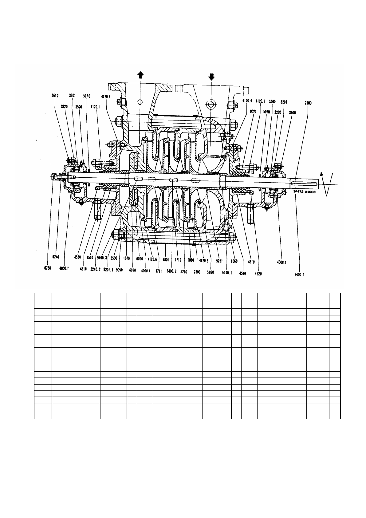
Size MML 80, 100, 125
Stuffing box housing : Type N
No.
1060 Suction casing 1 4120.6 O-ring ASBESTOS 1 9050 Tie bolt S C M 3 8
1070 Discharge casing 1 4510 Stuffing box housing 2 9201.1 Hexagonal nut S 45 C 16
1080 Stage casing 4520 Stuffing box gland 2 9400.1 Key S 45 C 1
1710 Diffuser 4610 Stuffing box packing TOMBO 3300 8 9400.2 Key S 45 C
1711 Diffuser last stage 1 5020 Casing wear ring 9400.3 Key S 45 C 1
2100 Shaft 1 5070 Deflector S 35 C 2
2300 Impeller 5210 Stage sleeve
3201 Clamping sleeve SS 400 2 5240.1 Shaft protecting sleeve 1
3220 Cylindrical roler bearing NU KC3
3500 Bearing housing FC 200 2 5251 Spacer sleeve 1
3600 Bearing cover FC 200 1 5500 Washer SS 400 16
3610 Bearing end cover FC 200 1 6010 Balance disc 1
4000.1 Flat gasket TOMBO 1630 2 6020 Balance disc. Seat 1
4000.4 Flat gasket TOMBO 1900 1 6230 Rotor position indicator BSBME 1 1
4120.1 O-ring N B R 2 6240 Pivot for indicator S 30 C 1
4120.4 O-ring N B R 2 6801 Cladding S P C C 1
4120.5 O-ring N B R 9021 Stud SUS 420J2 4
Name
Material Pcs No
+H
2 5240.2 Shaft protecting sleve 1
Name
Material Pcs No.
Name
Material Pcs
- 29 -

Size MML 80, 100, 125
Stuffing box housing : Type HW
No.
1060 Suction casing FC 250 1 4120.3 O-ring N B R 2 6240 Pivot for indicator SS 40 1
1070 Discharge casing FC 250 1 4120.4 O-ring VITON 2 6801 Cladding S P C C 1
1080 Stage casing FC 250 4120.5 O-ring VITON 9021 Stud SUS 420 J2 4
1650 Cooling cover FC 200 2 4120.6 O-ring ASBESTOS 1 9050 Tie bolt S C M 3 8
1710 Diffuser FC 200 4510 Stuffing box housing FC 250 2 9201.1 Hexagonal nut S 45 C 16
1711 Diffuser last stage FC 200 1 4520 Stuffing box gland FC 200 2 9050.1 Key S 45 C 1
2100 Shaft S 45 C 1 4610 Stuffing box packing TOMBO 3300 8 9400.2 Key S 45 C
2300 Impeller FC 200 5020 Casing wear ring FC 200 9400.3 Key S 45 C 1
3201 Clamping sleeve SS 400 2 5070 Deflector S 35 C 2
3220 Cylindrical roler bearing NU KC3
3500 Bearing housing FC 200 2 5240.1 Shaft protecting sleeve FC 200 1
3600 Bearing cover FC 200 1 5240.2 Shaft protecting sleve FC 200 1
3610 Bearing end cover FC 200 1 5251 Spacer sleeve FC 200 1
4000.1 Flat gasket TOMBO 1630 2 5500 Washer SS 400 16
4000.4 Flat gasket TOMBO 1900 1 6010 Balance disc FC 200 1
4120.1 O-ring VITON 2 6020 Balance disc. Seat FC 200 1
4120.2 O-ring N B R 2 6230 Rotor position indicator BSBME 1 1
Name
Material Pcs No
+H
2 5210 Stage sleeve FC 200
Name
Material Pcs No.
Name
Material Pcs
7E : Cooling water inlet 24E : Quenching inlet
7A : Cooling water outlet 24A : Quenching outlet
- 30 -

Size MML 150
Stuffing box housing : Type N
No.
1060 Suction casing 1 4510 Stuffing box housing 2 6240 Pivot for indicator S 30 C 1
1070 Discharge casing 1 4520 Stuffing box gland 2 6801 Cladding S P C C 1
1080 Stage casing 4610 Stuffing box packing TOMBO 3300 8 9021 Stud SUS 420 J2 4
1710 Diffuser 5020 Casing wear ring 9050 Tie bolt S C M 3 8
1711 Diffuser last stage 1 5070 Deflector S 35 C 2 9201.1 Hexagonal nut SUS 420 J2 16
2100 Shaft 1 5090 Spacer ring FC 200 2 9210.1 Nut SUS 420 J2 1
2300 Impeller 5210 Stage sleeve 9400.1 Nut S 45 C 1
3220 Cylindrical roler bearing NU 410 C3 2 5240.1 Shaft protecting sleeve 1 9400.2 Key S 45 C
3500 Bearing housing FC 200 2 5240.2 Shaft protecting sleeve 1 9400.3 Key S 45 C 1
3600 Bearing cover FC 200 1 5250.1 Spacer sleeve 1
3610 Bearing end cover FC 200 1 5250.3 Spacer sleeve 1
4000.1 Flat gasket TOMBO 1630 2 5251 Spacer sleeve 1
4000.4 Flat gasket TOMBO 1900 1 5252 Spacer sleeve 1
4120.1 O-ring N B R 4 5500 Washer SS 400 16
4120.4 O-ring N B R 2 6010 Balance disc 1
4120.5 O-ring N B R 6020 Balance disc. Seat 1
4120.6 O-ring ASBESTOS 1 6230 Rotor position indicator BSBME 1 1
Name
Material Pcs No
Name
Material Pcs No.
Name
Material Pcs
- 31 -

Size MML 150
Stuffing box housing : Type HW
No.
1060 Suction casing FC 250 1 420.4 O-ring VITON 2 6010 Balance disc 1
1070 Discharge casing FC 250 1 4120.5 O-ring VITON 6020 Balance disc seat 1
1080 Stage casing FC 250 4120.6 O-ring ASBESTOS 1 6230 Rotor position indicator 1
1650 Coolng cover FC 200 2 4510 Stuffing box housing FC 250 2 6240 Pivot for indicator 1
1710 Diffuser FC 200 4520 Stuffing box gland FC 200 2 6801 Cladding 1
1711 Diffuser last stage FC 200 1 4610 Stuffing box packing TOMBO 3300 8 9021 Stud 4
2100 Shaft S 45 C 1 5020 Casing wear ring FC 200 9050 Tie bolt 8
2300 Impeller FC 200 5070 Deflector S 35 C 2 9201.1 Hxagonal nut 16
3220 Cylindrical roler bearing XU 410 C3 2 5090 Spacer ring FC 200 2 9210.1 Nut 1
3500 Bearing housing FC 200 2 5210 Stage sleeve FC 200 9210.2 Nut 1
3600 Bearing cover FC 200 1 5240.1 Shaft protecting sleeve FC 200 1 9400.1 Key 1
3610 Bearing end cover FC 200 1 5240.2 Shaft protecting sleeve FC 200 1 9400.2 Key
4000.1 Flat gasket TOMBO 1630 2 5250.1 Spacer sleeve FC 200 1 9400.3 Key 1
4000.4 Flat gasket TOMBO 1900 1 5250.3 Spacer sleeve FC 200 1
4120.1 O-ring VITON 4 5251 Spacer sleeve FC 200 1
4120.2 O-ring N B R 2 5252 Spacer sleeve FC 200 1
4120.3 O-ring N B R 2 5500 Washer SS 400 16
Name
Material Pcs No
Name
Material Pcs No.
Name
Material Pcs
7E : Cooling water inlet 24E : Quenching inlet
7A : Cooling water outlet 24A : Quenching outlet
- 32 -

TORISHIMA PUMP MFG.CO.,LTD.
Head Office & Works : 1 −8, Miyata−ch akatsuki City, Osaka, Japan. Phone : 0726−95−0551 Telex : 5336568 TORIPUJ Telefax: 0726−93−1288−1 o, T
TORISHIMA SINGAPORE
TORISHIMA SINGAPORE PTE.LTD.
TORISHIMA HONGKONG
TORISHIMA HONGKONG LIMITED
TORISHIMA MALAYSIA
TORISHIMA MALAYSIA SDN.BHD
TORISHIMA U.A.E
MIDDLE EAST OFFICE
TORISHIMA U.K.
EUROPE OFFICE
TORISHIMA U.S.
U.S. OFFICE
TORISHIMA INDONESIA
PT. TORISHIMA GUNA INDONESIA
PT. TORISHIMA GUNA ENGINEERING
PT. GETEKA FOUNINDO
30 Ubi Crescent # 01 ˘ 02 Ubi Tech Park Singapore 408566 Phone : (65)67790123 Fax : (65) 67796900
Unit 603, 6/F., Tower III, Enterprise Square, 9 Sheung Yuet Road, Kowloon, Hongkong
Suite 906, 19th Floor, Kenanga International. Jalan Sultan Ismail, 50250 Kuala Lumpur
5th Floor, office No.503, Al Salmeen Golden Tower, P.O Box.:72197, Electra Street, Abu Dhabi. U.A.E
20/23 Woodside place Glasgow G3 7QF, Scotland, United Kingdom
82B Daniels Road, Charlton, MA01507, United States of America
JL Rawa Sumur Timur No.1, Pulogadung Industrial Estate, PO Box :1111 JAT., Jakarta 13011, onesia Ind
JL Rawa Sumur Timur No.1, Pulogadung Industrial Estate, PO Box :1111 JAT., Jakarta 13011 donesia
JL Pulo Ayang Kav AA2, Pulogadung Industrial Estate, PO Box :1111 JAT., Jakarta 13011, Indo sia ne
Phone : (852) 2795−1838 Fax : (852) 2754−3293
Phone : (603 ) 2715−0068 Fax : ( 603 ) 2715−0019
Phone: (971)2−6743880 Fax:(971)2−6743881
Phone: (44) 1236−441632 Fax:(44) 1236−702875
Phone: (1 )866−374−1130 Fax:(1 )508−248−9321
Phone : (62)21−460−3963 (Hunting) Fax : (62)21− 460−3937
Phone : (62)21−460−3963 (Hunting) Fax : (62)21− 460−3937
Phone : (62)21−460−3963 (Hunting) Fax : (62)21− 460−3937
, In
 Loading...