

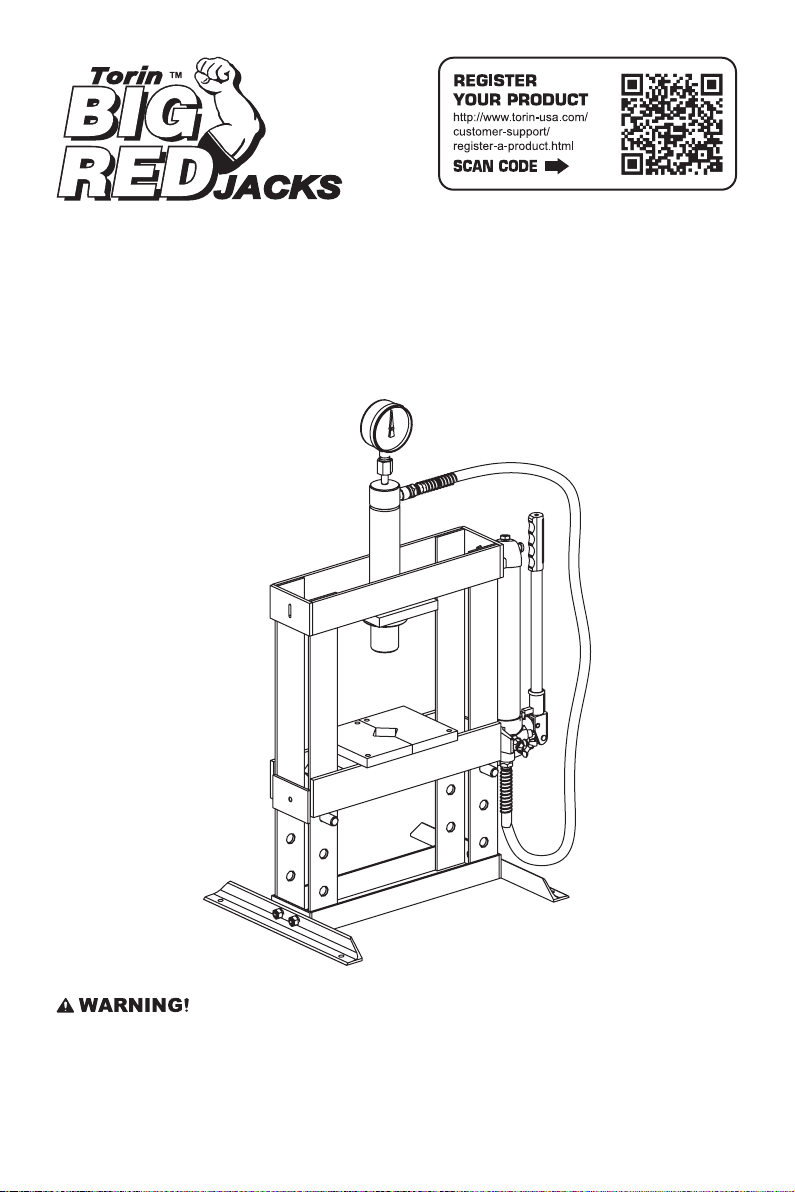
Torin BIG RED TY10003 Owner's Manual
OWNER’S MANUAL
10 TON HYDRAULIC BENCHTOP
SHOP PRESS
Item: TY10003
Questions, problems, missing parts? Before returning to your retailer, call our customer service department at
1-888-44-TORIN (1-888-448-6746), 8 a.m.- 5 p.m., PST, Monday-Friday.
Read carefully and understand all ASSEMBLY AND OPERATION INSTRUCTIONS before operating. Failure
to follow the safety rules and other basic safety precautions may result in serious personal injury.
Version 06012017

IMPORTANT
Before You Begin Register This Product.
For future reference, record the model name, model number, date of manufacture and purchase date of this
product. You can nd this information on the product.
Model Name ________________________
Model Number ________________________
Date of Manufacture _______________________
Date of Purchase ________________________
OWNER / USER RESPONSIBILITY
DO NOT OPERATE OR REPAIR THIS PRODUCT WITHOUT READING THIS MANUAL.
Read and follow the safety instructions. Keep Instructions readily available for operators. Make certain all
operators are properly trained and understand how to safely and correctly operate the product. By proceeding
you agree that you fully understand and comprehend the full contents of this manual. Failure to operate this
product as intended may cause injury or death. The manufacturer is not responsible for any damages or injury
caused by improper use or neglect. Allow product operation only with all parts in place and operating safely.
Use only genuine replacement parts. Service and maintain the product only with authorized or approved
replacement parts; negligence will make the product unsafe for use and will void the warranty. Carefully
inspect the product on a regular basis and perform all maintenance as required. Store these instructions
in a protected dry location. Keep all decals on the product clean and visible. Do not modify and/or use for
any application other than that for which this product was designed. If you have any questions relative to a
particular application, DO NOT use the product until you have rst contacted the distributor or manufacturer to
determine if it can or should be performed on the product.
For technical questions please call 1-888-448-6746.
INTENDED USE
This equipment is designed for automotive, truck, implement, eet, and industrial repair shops where pressing,
bending, straightening and forming tasks are required. Typical applications include installation and removal of
alternator and power steering pump bearings, axle bearings, transmission bearings, seals, U-joints and many
other jobs.
TECHNICAL SPECIFICATIONS
Description
Item
Capacity
Bed Opening
Work Range
Stroke Length
Inside Bed Dimensions L x W
Dimensions L x W x H
Winch Included
TY10003
1 0 TON
4.33 inch
0~13-3/4 inch
6-7/8 inch
4-5/16 x 13-3/8 inch
23-3/16 x 17-11/16 x 41-15/16 inch
No
2

GENERAL SAFETY RULES
WARNING:
in serious injury.
CAUTION:
and have developed a thorough understanding of how the Shop Press works.
WARNING: The warnings, cautions, and instructions discussed in this instruction manual cannot
cover all possible conditions or situations that could occur.
that common sense and caution are factors which cannot be built into this product, but must be supplied
by the operator.
Read and understand all instructions. Failure to follow all instructions listed below may result
Do not allow persons to operate or assemble this Shop Press until they have read this manual
It must be understood by the operator
GENERAL SAFETY RULES
IMPORTANT SAFETY CONSIDERATIONS
SHOP PRESS USE AND CARE
Do not modify the Shop Press in any way.
•
safety and could affect the life of the equipment. There are specic applications for which the Shop Press
was designed.
Always check of damaged or worn out parts before using the Shop Press.
•
Shop Press operation. Replace or repair damaged or worn parts immediately.
Store idle Shop Press.
•
children. Inspect it for good working condition prior to storage and before re-use.
Not for use by children
•
Do not use under the inuence of drugs or alcohol.
•
Ensure children and other bystanders
•
When Shop Press is not in use, store it in a secure place out of the reach of
or people with reduced mental capacity.
Unauthorized modication may impair the function and/or
Broken parts will affect the
are kept at a safe distance when using shop press.
INSPECTION
• Inspect the shop press carefully before each use. Ensure the shop press is not damaged, excessively worn,
or missing parts.
• Do not use the shop press unless it is properly lubricated.
• Using a shop press that is not in good clean working condition or properly lubricated may cause serious
injury.
• Inspect the work area before each use. Make sure it is free and clear of any potential hazards.
3

DO NOT OPERATE OR REPAIR THIS EQUIPMENT WITHOUR READING THIS MANUAL.
To maintain the Shop Press and user safety, the responsibility of the owner is to read and follow these
instructions. Inspect the service shop press for proper operation and function. Keep instructions readily
available for equipment operators. Make certain all equipment operators are properly trained; understand
how to safely and correctly operate the unit. Allow unit operation only with all parts in place and operating
properly. Use only genuine replacement parts. Service and maintain the unit only with authorized or approved
replacement parts negligence will make the shop press unsafe for use and void the warranty. Carefully inspect
the unit on a regular basis and perform all maintenance as required. Store these instructions in the handle of
your shop press. Keep all decals on the unit clean and visible.
Safety: always follow safety precautions when installing and operating this shop press. Keep all decals on
the unit clean and visible. Before proceeding that you fully understand and comprehend the full contents of
this manual. Failure to operate this equipment as directed may cause injury or death. The distributor is not
responsible for any damages or injury caused by improper use or neglect.
SAFETY MARKINGS
WARNING!
1. Study, understand, and follow all instructions before operating the device.
2. Do not exceed rated capacity.
3. Prior to use, make sure the press is securely anchored.
4. The press shall be installed and operated in accordance with federal (OSHA), state, and local safety
standards.
5. Ensure the work area is clean and free of any hazards before operation.
6. Operators and observers shall wear eye protection that meets ANSI Z87.1 and OSHA standards.
7. Keep hands, arms, feet, and legs out of the work area. Accidental slippage can result in personal injury.
8. Use appropriate guarding to contain any pieces that may break or y apart when applying force.
9. Use only press accessories having a capacity rating equal to or greater than the capacity of the press.
10. Verify lift cables are slack before pressing on the bolster.
11. Avoid off-center loads.
12. No alterations shall be made to the product.
13. Do not use this press for any use other than the manufacturer specied usage.
14. Failure to heed and understand these instructions and markings may result in personal injury, property
damage, or both.
4

GENERAL SAFETY INSTRUCTIONS
PLEASE READ THESE INSTRUCTIONS CAREFULLY. NOTE THE SAFETY INSTRUCTIONS AND
WARNINGS. USE THE PRODUCT CORRECTLY AND WITH CARE FOR THE PURPOSE OF WHICH IT IS
INTENDED. FAILURE TO DO SO MAY CAUSE DAMAGE TO PROPERTY AND/OR SERIOUS PERSONAL
INJURY. PLEASE KEEP THIS INSTRUCTION MANUAL SAFE FOR FUTURE USE.
We’ve done all we can to assure this press offers the outmost in safety, but you have to do your part. No
amount of warning can take the place of your good judgment, so make sure it’s the rst thing you bring to any
job. Beyond that here are some obvious tips:
• Steel and other materials can shatter, so always use protective eyewear that complies with the appropriate
ANSI code.
• If you detect anything that may indicate imminent structural failure, stop using the press immediately and
inspect it thoroughly.
• Bolt the press to the oor if it is to be used on bulky or unstable items.
• Do not use press to compress springs or any other item that could disengage and cause a potential ying
hazard.
• Use this press for the purpose for which it is intended. Do not use it for any other purpose it is not designed
to perform.
• Keep children and unauthorized persons away from the work area.
• Contain loose tting clothing. Remove ties, watches, rings and other loose jewelry and contain long hair.
• Wear ANSI approved impact safety goggles, full-face impact safety shield and heavy-duty work gloves
when operating the press.
• Keep proper balance and footing, do not overreach and wear nonskid footwear.
• Only use this press on a surface that is stable, level, dry and not slippery, and capable of sustaining
the load. Keep the surface clean, tidy and free form unrelated materials and ensure that there is adequate
lighting.
• Inspect the press before each use. Do not use if bent, broke, cracked, leaking or otherwise damaged. Do
not use if any suspect parts are noted or if the shop press has been subjected to a shock load.
• Check to ensure that all applicable bolts and nuts are rmly tightened.
• Ensure that work piece is center-loaded and secure.
• Keep hands and feet away from bed area at all times.
• Do not use the shop press to compress spring or any other item that could disengage and cause a potential
hazard. Never stand directly in front of loaded press and never leave loaded press unattended.
• Do not operate the press when you are tired or under the inuence of alcohol, drugs or an intoxicating
medication.
• Do not allow untrained persons to operate the press.
• Do not make any modications to the press.
• Do not use brake uid or any other improper uid and avoid mixing different types of oil when adding
hydraulic oil. Only good quality hydraulic jack oil can be used.
• Do not expose the press to rain or any other kind of bad weather.
• If the press needs repairing and/or there are any parts that need to be replaced, have it repaired by
authorized technicians and only use the replacement parts supplied by the manufacturer.
5
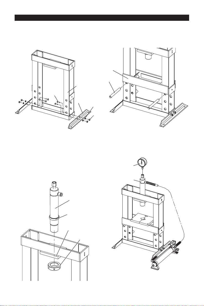
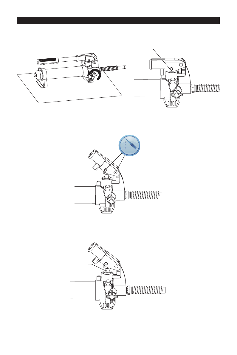
ASSEMBLY
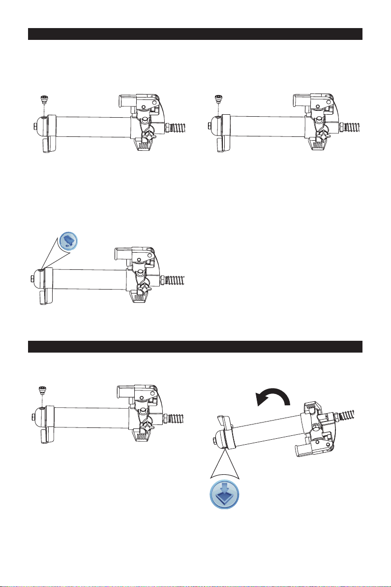
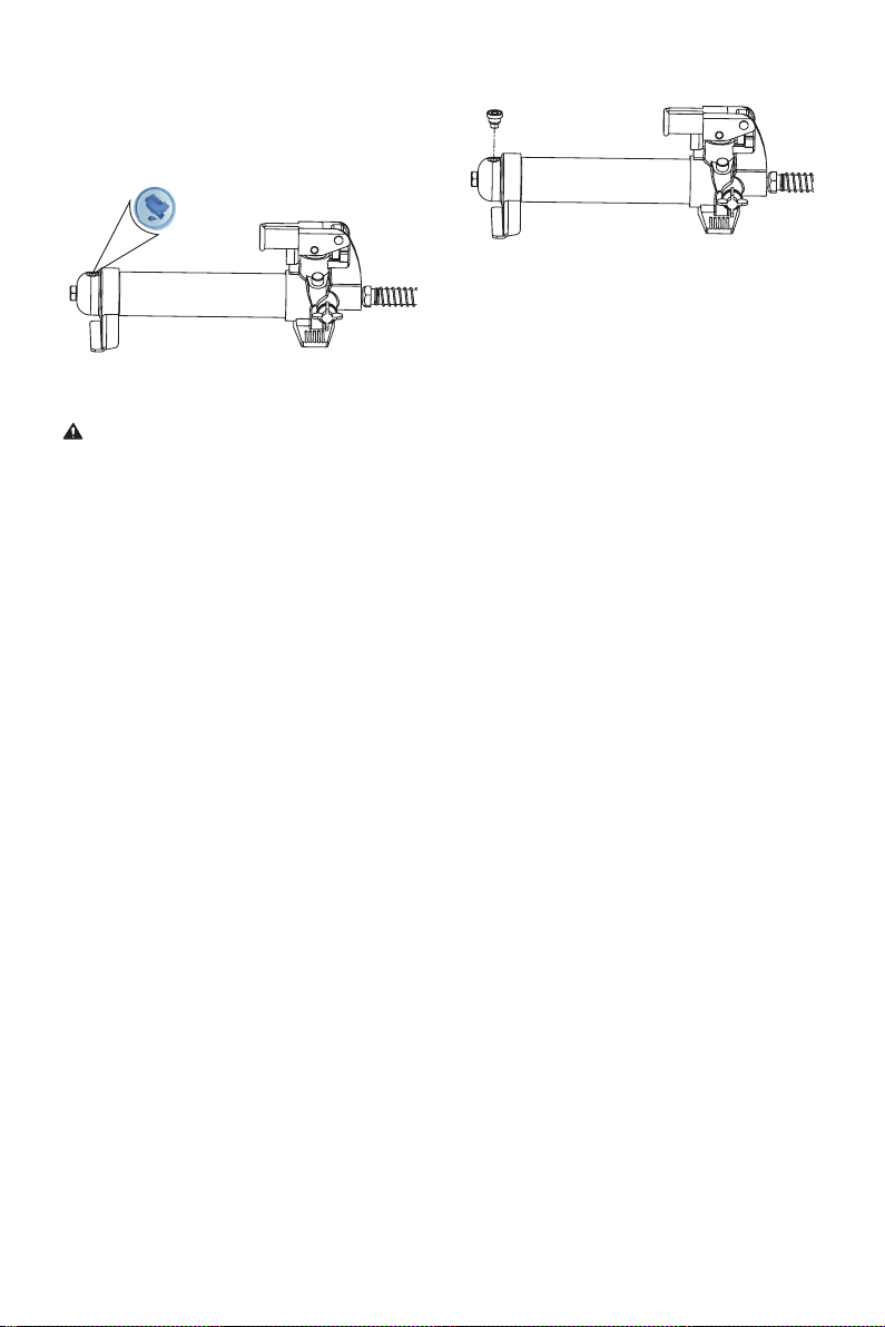
All numbers in parenthesis () refer to the index number from the parts breakdown.
1. Attach the two rail sections (8) to the upright
frame (17) using bolts (7), lock washers (10) and
nuts (11).
17
17
7
7
8
8
2. Insert the hydraulic cylinder (3) from the top
side of frame. Once the cylinder is inserted into
the frame support plate (15) make sure that
the round lifting ring (16) is seated flat on the
cylinder support plate (15). Then attach the
round threaded nut (14) to the hydraulic cylinder.
Turn clockwise to screw the round nut (16) onto
threaded shaft on the ram. Tighten round nut (3).
3. Insert lower bolster pins (9) into the bottom holes
on the up right frame, then insert the lower bolster
(13) into press frame, onto lower bolster pins.
13913
9
10
10
11
11
4. Locate the hydraulic hose fitting on the cylinder
and assemble the pressure gauge (1) to the
pressure gauge connection tting, on the top of
the hydraulic cylinder (3).
1
313
3
3
16
16
15
15
14
14
5. Tighten all bolts and screws.
6
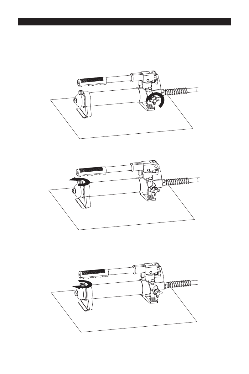
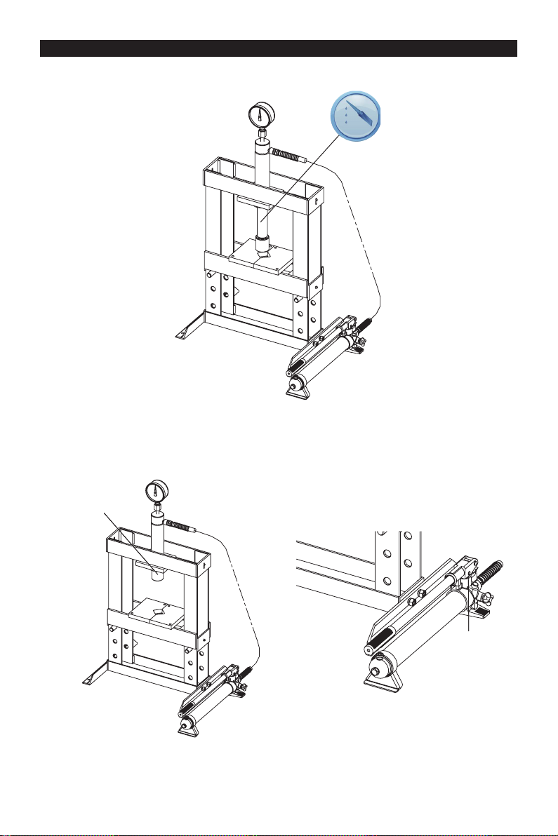
SYSTEM AIR PURGE PROCEDURE
IMPORTANT: BEFORE FIRST USE
All numbers in parenthesis () refer to the index number from the parts breakdown. Perform the following Air
Purge Procedure to remove any air that may have been introduced into the hydraulic system as a result of
product shipment and handing. This step is to be completed without and weight on the shop press.
1. Turn the Release Valve counter-clockwise to release the pressure in the pump and hose.
2. Lossen bleeder screw to release air from system.
3. Check the oil level and add oil if necessary. (See instruction in Maintenance Section “To Add Oil”.)
4. CLose bleeder screw.
7
BEFORE USE
1. Before using this product, read the owner's manual completely and familiarize yourself thoroughly with the
product and the hazards associated with its improper use.
2. Perform the air purge procedure. (See previous instructions for system purge procedure.)
3. Inspect before each use. Do not use if bent, broken or cracked components are noted.
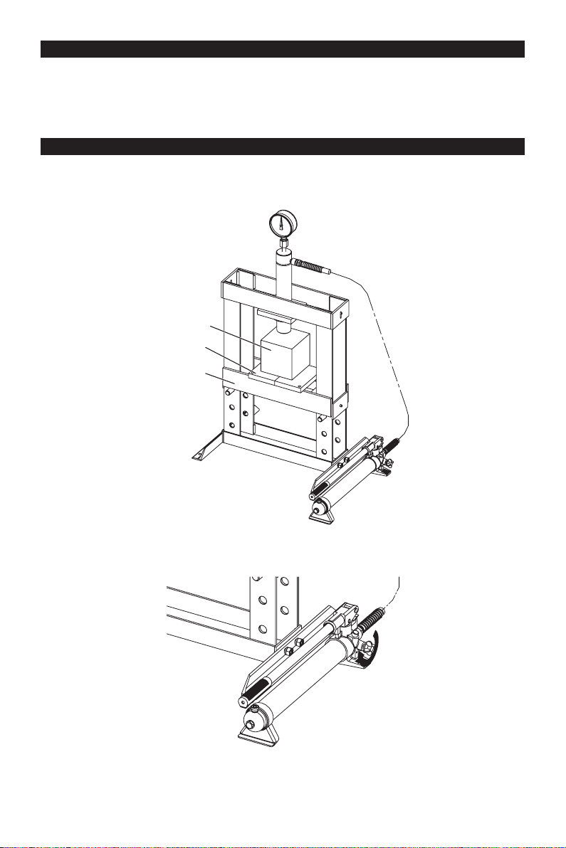
OPERATION
All numbers in parenthesis () refer to the index number from the parts breakdown.
1. Place the bolster plates (12) on press bed frame (13), then insert onto the bolster plates.
Work piece
12
13
2. Close the release valve by turning it clockwise until it is rmly closed.
8
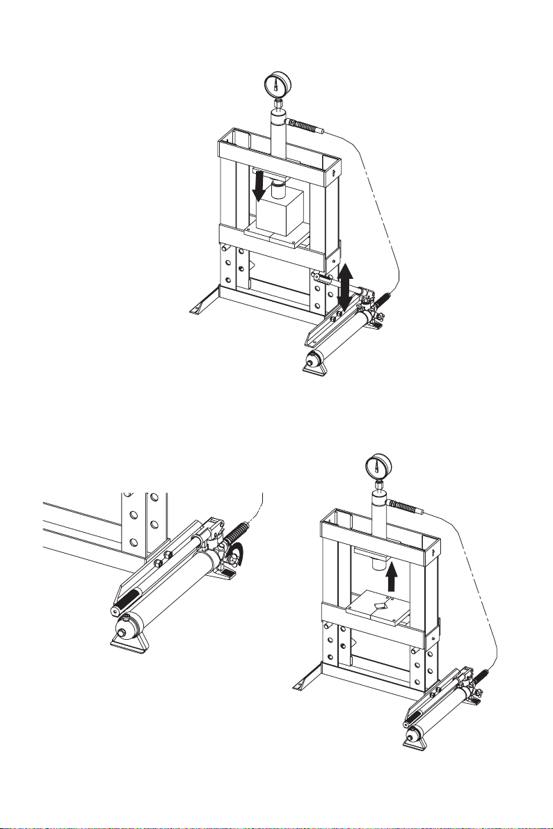
3. Pump the handle until ram nears work piece. Align work piece and ram to ensure center-loading. Pump the
handle to apply load onto work piece.
4. When work is completed, stop pumping the
handle. Slowly turn the release valve counterclockwise in small increments until ram is free
from work piece. Cautiously remove work piece
from press.
5. Fully retract ram after work piece has been
removed from press.
9

MAINTENANCE INSTRUCTIONS
If you use and maintain your equipment properly, it will give you many years of service. Follow the
maintenance instructions carefully to keep your equipment in good working condition. Never perform any
maintenance on the equipment while it is under a load.
Inspection
You should inspect the product for damage, wear, broken or missing parts (e.g.: pins) and that all components
function before each use. Follow lubrication and storage instructions for optimum product performance.
Binding
If the product binds while under a load, use equipment with equal or a larger load capacity to lower the load
safely to the ground. After un-binding; clean, lubricate and test that equipment is working properly. Rusty
components, dirt, or worn parts can be causes of binding. Clean and lubricate the equipment as indicated in
the lubrication section. Test the equipment by lifting without a load. If the binding continues contact Customer
Service.
Cleaning
If the moving parts of the equipment are obstructed, use cleaning solvent or another good degreaser to clean
the equipment. Remove any existing rust with a penetrating lubricant.
Lubrication
This equipment will not operate safely without proper lubrication. Using the equipment without proper
lubrication will result in poor performance and damage to the equipment. Some parts in this equipment are not
self-lubricating inspect the equipment before use and lubricate when necessary. After cleaning, lubricate the
equipment using a high grade light penetrating oil or lubricating spray.
• Use a good lubricant on all moving parts.
• For light duty applications, use lubrication once a month.
• For heavy and constant use, lubrication is recommended every week.
• NEVER USE SANDPAPER OR ABRASIVE MATERIAL ON THESE SURFACES!
Rust Prevention:
Check rams and pump plungers on the power unit assemblies daily for any signs of rust or corrosion.
Without a load on the equipment extended hydraulic rams to check if signs of rust are visible; clean as
needed.
Grease Fittings
Some models contain grease ttings that will regularly need to be greased and lubricated.
How the Ram Operates
With release valve closed, an upward stroke of the jack handle draws oil from the reservoir tank into the
plunger cavity. Hydraulic pressure holds the valve closed, which keeps the oil in the plunger cavity. A
downward stroke of the jack handle releases oil into the cylinder, which forces the ram out. This extends the
ram. When the ram reaches maximum extension, oil is bypassed back into the reservoir to prevent an over
extended ram stroke and possible damage to the vérin. Opening the release valve allows oil to ow back into
reservoir. This releases hydraulic pressure on the ram, which results in lowering the ram.
Storing the Ram
1. Fully Retract Ram after use.
2. Place the handle in the upright position.
3. Store in a dry location, recommended indoors.
Note: If the press is stored outdoors, be sure to lubricate all parts before and after use to ensure the press
stays in good working condition.
10
TO ADD JACK OIL:
The hydraulic cylinder assembly contains hydraulic uid that must be kept at approximately 80% full at all
times for proper operation. To check the level and to ll remove oil ller plug.
1. Remove the bleeder screw.
2. Set Pump Unit on a level surface. Add0.22 quarts
(about 7.43oz., or 630ml) of oil.
Use a high grade anti-foaming hydraulic oil.
KEEP DIRT AND OTHER MATERIALS CLEAR
WHEN POURING.
TO REPLACE JACK OIL
3. Replace the bleeder screw.
4. Perform the Air Purge Procedure.
1. Remove the bleeder screw. 2. Turn the Pump Unit on its side so that old oil will
drain from the oil ll hole.
11
3. Set Pump Unit on a level surface. Add0.22 quarts
4. Replace the bleeder screw.
(about 7.43oz., or 630ml) of oil.
Use a high grade anti-foaming hydraulic oil.
KEEP DIRT AND OTHER MATERIALS CLEAR
WHEN POURING.
5. Perform the Air Purge Procedure.
ADDITIONAL WARNINGS:
• DO NOT USE MOTOR OIL IN THE JACK.
• ONLY USE ANTI-FOAMING JACK OIL.
• ALWAYS USE A GOOD GRADE HYDRAULIC JACK OIL.
• DO NOT USE HYDRAULIC BRAKE FLUID, ALCOHOL, GLYCERINE, DETERGENT, MOTOR OIL
ORDIRTY OIL.
• USE OF A NON-RECOMMENDED FLUID CAN CAUSE DAMAGE TO A JACK.
• AVOID MIXING DIFFERENT TYPES OF FLUID AND NEVER USE BRAKE FLUID, TURBINE OIL,
TRANSMISSION FLUID, MOTOR OIL OR GLYCERIN. IMPROPER FLUID CAN CAUSE PREMATURE
FAILURE OF THE JACK AND THE POTENTIAL FOR SUDDEN AND IMMEDIATE LOSS OF LOAD.
• DISPOSE OF HYDRAULIC FLUID IN ACCORDANCE WITH LOCAL REGULATIONS.
12
LUBRICATION
1. Clean the outside of the press with a dry, clean, and soft cloth. Periodically lubricate all joints and moving
parts with a long-lasting lubrication oil. Apply as needed.
2. When not in use, store the press in a dry location with ram and pump piston fully retracted. Periodically
check the rams for signs of rust or corrosion. Clean as needed and wipe with a soft non-abrasive clean
cloth.
Fully Retracted
Fully Retracted
13
LUBRICATION PUMP
1. When not in use, the Pump Unit should be stored with the Release Valve open and the Pump Piston fully
retracted.
Fully Retracted
2. A coating of light lubricating oil to pivot points, axles and hinges will help to prevent rust.
3. Periodically check the pump piston and ram for signs of rust or corrosion. Clean as needed and wipe with a
soft non-abrasive clean cloth.
Clean
14

TROUBLESHOOTING
WILL
NOT
LIFT
LOAD
WILL
NOT
HOLD
LOAD
WILL
NOT
LOWER
POOR
LIFTING
WILL NOT
LIFT TO
FULL
EXTENSION
X XX
X
X X
X X XX
X
X
X
X
Safe Operating Temperature is between 40°F – 105°F (4°C - 41°C)
X X
X
CAUSES AND SOLUTIONS
Release valve is not completely closed
(Turn handle clockwise).
Weight Capacity Exceeded.
Air is in the hydraulics.
Purge air from system.
Low oil level. Add oil as required.
Oil reservoir is overlled.
Drain excessive oil.
Lubricate moving parts.
Jack is binding or foreign obstruction
Power unit malfunctioning.
Replace the power unit.
Air Supply Inadequate
(For Units supplied with air ttings and air
pumps).
15
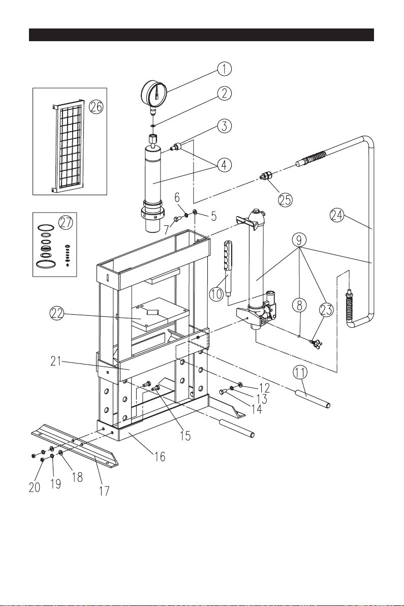
ASSEMBLY DIAGRAM
Optional
16

ASSEMBLY PARTS LIST
No. Part Description Qty
1 TY10003-04 Gauge (0-18 Ton) 1
2 TY12001.1-15 Rectangular seal 1
3 QF4.6(ASM) Female coupling valve 1
4 TY12001.1 Cylinder assembly 1
5 Washer M6 1
6 Spring washer M6 1
7 Socket head cap screw M6x16mm 1
8 GB308-8 Steel ball bearing Ø8mm 1
9 TY12001.2a Power unit 1
10 QF10-1(ASM) Handle assembly 1
11 TY10003-02 Support pin 2
12 Washer M8 1
13 Spring washer M8 1
14 Socket head cap screw M8x16mm 1
15 Hex head bolt M10x25mm 4
16 Frame assembly 1
17 Base 2
18 Washer M10 4
19 Spring washer M10 4
20 Nut M10 4
21 Lower bolster 1
22 TY12001-04 Bolster plate 2
23 QF4.2a(ASM) Release valve assembly 1
24 TY12001.2.3 Hose ZG1/4"×1200mm 1
25 QF4.4 Male couping valve 1
26 TY10003F.3 Safety guard 1
27 TY10003.MF Seal kit 1
17

WARRANTY NOTICE
This equipment is covered under a 1-year limited warranty when used as recommended. Only those
items listed with a Part # are available for purchase. For assistance with the operation or the availability of
replacement parts, contact our Parts and Warranty Department at 1-888-44-TORIN (1-888-448-6746). Please
have available a copy of your receipt, the model number of the product, serial number, and specic details
regarding your question.
Not all equipment components are available for replacement; illustrations provided are a convenient reference
of location and position in the assembly sequence.
The manufacturer reserves the rights to make design changes and or improvements to product lines
and manuals without notice.
WARRANTY INFORMATION
We want to know If you have any concerns with our products. If so, please call toll-free for Immediate
assistance. For additional web customer support help inquiries visit the Customer Service section at:
http://www.torin-usa.com.
18
 Loading...